WO2019130641A1 - 車両用メンバー部品及びそのプレス成形方法並びにプレス型 - Google Patents
車両用メンバー部品及びそのプレス成形方法並びにプレス型 Download PDFInfo
- Publication number
- WO2019130641A1 WO2019130641A1 PCT/JP2018/029593 JP2018029593W WO2019130641A1 WO 2019130641 A1 WO2019130641 A1 WO 2019130641A1 JP 2018029593 W JP2018029593 W JP 2018029593W WO 2019130641 A1 WO2019130641 A1 WO 2019130641A1
- Authority
- WO
- WIPO (PCT)
- Prior art keywords
- punch
- side wall
- plate
- press
- steel plate
- Prior art date
- Legal status (The legal status is an assumption and is not a legal conclusion. Google has not performed a legal analysis and makes no representation as to the accuracy of the status listed.)
- Ceased
Links
Images












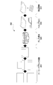

Classifications
-
- B—PERFORMING OPERATIONS; TRANSPORTING
- B21—MECHANICAL METAL-WORKING WITHOUT ESSENTIALLY REMOVING MATERIAL; PUNCHING METAL
- B21D—WORKING OR PROCESSING OF SHEET METAL OR METAL TUBES, RODS OR PROFILES WITHOUT ESSENTIALLY REMOVING MATERIAL; PUNCHING METAL
- B21D22/00—Shaping without cutting, by stamping, spinning, or deep-drawing
- B21D22/20—Deep-drawing
- B21D22/26—Deep-drawing for making peculiarly, e.g. irregularly, shaped articles
-
- B—PERFORMING OPERATIONS; TRANSPORTING
- B21—MECHANICAL METAL-WORKING WITHOUT ESSENTIALLY REMOVING MATERIAL; PUNCHING METAL
- B21D—WORKING OR PROCESSING OF SHEET METAL OR METAL TUBES, RODS OR PROFILES WITHOUT ESSENTIALLY REMOVING MATERIAL; PUNCHING METAL
- B21D24/00—Special deep-drawing arrangements in, or in connection with, presses
-
- B—PERFORMING OPERATIONS; TRANSPORTING
- B21—MECHANICAL METAL-WORKING WITHOUT ESSENTIALLY REMOVING MATERIAL; PUNCHING METAL
- B21D—WORKING OR PROCESSING OF SHEET METAL OR METAL TUBES, RODS OR PROFILES WITHOUT ESSENTIALLY REMOVING MATERIAL; PUNCHING METAL
- B21D37/00—Tools as parts of machines covered by this subclass
- B21D37/02—Die constructions enabling assembly of the die parts in different ways
-
- B—PERFORMING OPERATIONS; TRANSPORTING
- B21—MECHANICAL METAL-WORKING WITHOUT ESSENTIALLY REMOVING MATERIAL; PUNCHING METAL
- B21D—WORKING OR PROCESSING OF SHEET METAL OR METAL TUBES, RODS OR PROFILES WITHOUT ESSENTIALLY REMOVING MATERIAL; PUNCHING METAL
- B21D53/00—Making other particular articles
- B21D53/88—Making other particular articles other parts for vehicles, e.g. cowlings, mudguards
-
- B—PERFORMING OPERATIONS; TRANSPORTING
- B62—LAND VEHICLES FOR TRAVELLING OTHERWISE THAN ON RAILS
- B62D—MOTOR VEHICLES; TRAILERS
- B62D25/00—Superstructure or monocoque structure sub-units; Parts or details thereof not otherwise provided for
Definitions
- the present invention relates to a vehicle member component, a press forming method thereof, and a press mold, and more specifically, a vehicle member component having a thin portion formed on a side wall portion of a substantially hat cross sectional shape (including a substantially U-shaped cross sectional shape)
- the present invention relates to a press forming method for forming the vehicle member component and a press die used for the press forming method.
- Patent Document 1 shows an upper mold 101 having a concave hat cross section and a side pad attached to the lower end of a bending blade of the upper mold 101 via a spring or the like.
- a pressing die (compressing force applying device) 100 having a 105 and applying a compressive force to the side wall portion W1 of the member part W0 having a hat cross-sectional shape without causing buckling during a bending and forming process, A press forming method for removing residual stress is disclosed.
- the side wall portion disposed in the vertical direction of the vehicle is a portion where the plate thickness can be reduced in strength and rigidity of the vehicle, and the vehicle horizontal direction Since it is generally formed to be longer than the central portion disposed in the above, it is also a part where the effect of weight reduction by thinning of the plate thickness can be greatly expected.
- Patent Document 1 It was considered to form a thin-walled portion on the side wall portion having a substantially hat cross-sectional shape by bending using the press forming method and the press die disclosed in No. 1.
- the press forming method and the press die disclosed in Patent Document 1 apply a compressive force in the wall height direction to the side wall portion having a substantially hat cross-sectional shape during the process of bending the steel plate, and residual stress is generated.
- the thin-walled part may be buckled by the compressive force applied to the side wall part. Therefore, it is not easy to form a thin portion on the side wall portion having a substantially hat cross-sectional shape.
- An object of the present invention is to provide a vehicle member part that can be realized in press processing, a press forming method for forming the vehicle member part, and a press die used for the press forming method.
- One aspect of the present invention for solving the above-mentioned problems is formed into a substantially hat cross-sectional shape including a central portion and side wall portions standing upright on both left and right sides by pressing a steel plate of substantially uniform thickness.
- Component parts of the vehicle In the side wall portion, an in-plate displacement surface formed by displacing the inner surface of the plate from the first step portion formed at the inner edge of the plate at the base end bent from the left and right ends of the central portion to the tip
- An outboard displacement surface formed by displacing the outer surface of the plate from the second step formed at the outer edge of the tip of the tip to the base end toward the inner end of the plate;
- a thin-walled portion having a thickness smaller than the thickness of the central portion is formed by the in-plate displacement surface and the plate-out displacement surface.
- the in-plate displacement surface is formed by the inner surface of the plate being displaced to the outer side from the first step portion formed on the inner edge of the plate at the base end bent from the central portion to the tip end And an out-of-plate displacement surface formed by displacement of the out-plate surface from the second step formed at the distal end of the plate to the outboard edge from the second step to the base end.
- an out-of-plate displacement surface formed by displacement of the out-plate surface from the second step formed at the distal end of the plate to the outboard edge from the second step to the base end.
- Middle part in the wall height direction of the side wall part which can secure the strength and rigidity of the vehicle even if the thickness is reduced while leaving thick parts at the central end and the shoulder R and shoulder and the base end and tip of the side wall A thin portion can be formed in the area (between the first step and the second step).
- the thin-walled portion in the side wall portion is formed by pressing a steel plate having a substantially uniform thickness. Therefore, it is possible to easily realize high-tensification of a steel plate and partial thinning of a plate thickness without using a new process such as tailored blank welding and equipment in a member member for a vehicle. As a result, it is possible to easily achieve both the reduction in weight and the increase in strength of the vehicle member component.
- a flange portion thicker than the thin-walled portion is extended to the outside of the side wall portion at the front end portion of the side wall portion.
- the flange portion thicker than the thin portion is extended to the outside of the side wall portion at the front end portion of the side wall portion.
- the flange portion can be formed at the front end portion of the side wall portion, and the reduction in weight and the increase in strength of the member member for a vehicle can be more easily achieved at the same time.
- the amount of displacement of the in-plate displacement surface with respect to the plate inner surface and the amount of displacement of the out-of-plate displacement surface with respect to the plate outer surface are the same. It is possible to reduce the eccentric load that causes bending or buckling deformation. Therefore, while maintaining a predetermined strength and rigidity, it is possible to increase the decreasing rate of the thickness of the thin portion to the thickness of the steel plate, and it is possible to further facilitate weight reduction and high strength in vehicle member parts It can be done.
- the in-plate displacement surface on the tip end side in the second step portion is displaced to the outside of the in-plate displacement surface from the in-plate displacement surface on the thin portion side.
- the in-plate displacement surface on the tip end side in the second step portion is displaced outward from the in-plate displacement surface on the thin portion side.
- the part can be bent stepwise to form a shape freezing folding line on the side wall part.
- the distance between the left and right distal end portions can be formed larger than the distance between the left and right proximal end portions. Therefore, it is possible to enhance axial torsional rigidity and the like in the vehicle member component while reducing the amount of springback and the amount of warpage of the side wall portion of the vehicle member component. As a result, it is possible to further improve the weight reduction and the high strength of the vehicle member part.
- the other aspect of this invention is the press-forming method of the member member for vehicles described in any one of (1) thru
- the steel plate is crushed in the thickness direction between the first step and the second step.
- squeeze processing in the press direction to form a thin-walled portion and finally bending a steel plate to form a tip portion, so that the distance from the first step to the second step on the bent side wall portion It is possible to reduce the thickness of the steel sheet while promoting the plastic flow of the steel sheet at the thin-walled part by crushing and scribing. Therefore, the residual stress in the thin portion can be made uniform by the plastic flow of the steel plate, and the amount of spring back, the amount of warpage, etc. in the side wall portion of the substantially hat cross sectional shape based on bending can be reduced.
- the thin-walled portion is formed by squeezing in the press direction while crushing the steel plate in the thickness direction between the first step portion and the second step portion, the thin portion is formed in the wall height direction (press Material width reduction effect that the material length in the wall height direction of the thin-walled part becomes longer along with the plastic flow and the material width of the steel plate can be shortened without fear of occurrence of buckling deformation etc. it can.
- the thickness of the thin portion is reduced by 35 to 45% with respect to the thickness of the central portion.
- the thickness of the thin portion is reduced by 35 to 45% with respect to the thickness of the central portion, so plastic flow of the steel sheet can be further promoted. Therefore, the difference in residual stress between the plate inner side and the plate outer side in the thin-walled portion can be further reduced by promoting plastic flow. As a result, it is possible to further reduce the amount of spring back, the amount of warpage, and the like in the side wall portion having a substantially hat cross-sectional shape.
- the other aspect of this invention is the press-forming method of the member member for vehicles described in (4), After bending the steel plate at the shoulder R portion of the central portion to form the base end of the side wall portion, the steel plate is crushed in the thickness direction at the first step portion and stretched in the pressing direction By bending back the steel plate in the direction inclining with respect to the pressing direction at the second step portion and bending back further in the pressing direction, the portion between the first step portion and the second step portion is formed.
- the inner and outer sides of the steel plate are drawn in the same direction in the press direction to form the thin portion, and at the same time, the side wall portion is bent stepwise at the second step portion, and finally the steel plate is The purpose is to form the tip end by bending.
- the steel plate is crushed in the thickness direction at the first step portion and drawn in the pressing direction, (2) While bending the steel plate in a direction inclining with respect to the pressing direction at the step portion, bending back processing is further performed in the pressing direction, so that the inner side of the plate and the plate between the first step portion and the second step portion At the same time as forming the thin-walled part by stretching the outer side in the press direction to the same extent, the side wall part is bent stepwise in the second step part and finally the steel plate is bent to form the tip part, Between the first step and the second step in the bent side wall, the inner and outer sides of the steel plate are equally stretched by bending and bending back, and the volume is fixed by the amount of stretching Plate thickness decreases substantially uniformly to form a thin portion Can.
- the thin-walled portion can be formed without performing the scribing process, so that the mold load (the bending of the bending blade, the mold opening, etc.) accompanying the forming of the thin-walled portion can be significantly reduced.
- the difference in residual stress generated between the plate inner side and the plate outer side in the thin-walled portion can be reduced by bending and bending back. That is, the tensile stress generated by the bending process is offset by the compressive stress generated by the bending process, and the residual stresses in the plate inner side and the plate outer side in the thin-walled portion can be made equal to each other. Therefore, since the difference in residual stress generated between the plate inner side and the plate outer side in the thin portion is small, it is possible to significantly reduce the amount of spring back, the amount of warpage, etc. in the side wall portion having a substantially hat cross section. In addition, by bending the side wall portion in a step-like manner at the second step portion, it is possible to promote shape freezing of the side wall portion and to further reduce the amount of springback and the like in the side wall portion.
- Still another aspect of the present invention is a press mold used in the press molding method described in (5) or (6),
- a lower mold punch having a substantially hat cross sectional shape, an upper mold having a bending blade formed opposite to a side wall of the lower mold punch, and the lower mold being suspended by the upper mold before the bending blade abuts on the steel plate And an upper pad for pressing the steel plate at the upper end of the punch,
- On the side wall of the lower punch On the side wall of the lower punch, an upper side wall portion crossing the upper end portion and coming into contact with the plate inner surface of the base end portion, and a first protrusion coming in contact with the in-plate displacement surface below and outward of the upper side wall portion Part is formed
- a lower side wall portion which intersects a lower end portion of the bending blade and abuts against a plate outer surface of the distal end portion on a side wall of the bending blade, and a second side which abuts the outboard displacement surface inward above the lower side wall portion
- the purpose
- the lower mold punch having a substantially hat cross-sectional shape, the upper mold having the bending blade formed facing the side wall of the lower mold punch, and the upper mold being suspended by the upper mold before the bending blade contacts the steel plate
- the upper end of the lower punch is provided with an upper pad for pressing the steel plate
- the side wall of the lower punch is provided with an upper side wall which intersects the upper end and is in contact with the inner surface of the base end
- a lower convex portion is formed in contact with the in-plate displacement surface in a lower and outer direction, and a lower wall portion intersecting the lower end portion of the bending blade and in contact with the plate outer surface of the tip portion is formed on the side wall of the bending blade; Since the second convex portion in contact with the out-of-plate displacement surface is formed at the upper inner side of the lower side wall portion, when the upper die is lowered toward the lower die punch, the upper pad is made of the steel plate of the lower die punch.
- the bending blade of the upper die bends the steel plate and causes the steel plate to be along the upper side wall portion of the lower punch and the side in the substantially hat cross sectional shape
- the first convex portion and the second convex portion narrow and squeeze the steel plate in the plate thickness direction, and the second convex portion is squeezed in the press direction to form a substantially hat
- a thin portion is formed on the side wall portion of the cross-sectional shape.
- the tip end portion can be formed by narrowing the steel plate between the first convex portion and the lower side wall portion at the press bottom dead center.
- the upper end of the first convex portion presses the steel plate to form a first stepped portion, and the lower end of the second convex portion crushes the steel plate to form a second stepped portion.
- the base end portion, the thin portion and the tip end portion are continuously formed on the side wall portion having a substantially hat cross-sectional shape by one press process, it is also necessary to add a new step and another press die. Absent.
- the micro convex-concave waveform continuous in the vertical direction is formed on the surface of the first convex portion, so that the first convex portion and the second convex portion are in the plate thickness direction
- the in-plate displacement surface of the side wall part is moved up and down by the micro uneven pattern formed on the surface of the first convex part. You can stretch more in the direction. Therefore, even if the reduction rate of the thickness of the thin portion relative to the thickness of the central portion (or steel plate) is small and compressive stress is likely to occur inside the steel plate, tensile stress is generated by the wave pattern on the in-plate displacement surface of the side wall. Can be added, and the difference in residual stress between the inside and the outside of the plate can be reduced to reduce the amount of springback, the amount of warpage, etc. in the side wall portion having a substantially hat cross-sectional shape.
- the lower punch is composed of a punch upper part integrated with a pedestal part and a punch lower part formed so as to be separated from the punch upper part in the press direction,
- the upper side wall portion is formed on an upper side wall of the punch upper portion,
- the first convex portion is divided into an upper convex portion formed at a lower side wall of the punch upper portion and a lower convex portion formed at an upper side wall of the punch lower portion,
- the punch lower portion is moved in the press direction in synchronization with the lowering operation of the upper mold from the time the upper mold is lowered to a position where the second convex portion and the lower convex portion have substantially the same height. Is preferred.
- the lower punch is composed of the punch upper portion integrated with the base portion and the punch lower portion formed to be able to be separated downward from the punch upper portion, and the upper side wall portion is the side wall upper portion of the punch upper portion
- the first convex portion is divided into an upper convex portion formed at the lower side wall of the punch upper portion and a lower convex portion formed at the upper side wall of the punch lower portion
- the punch lower portion is formed by Since the upper die moves in the press direction (downward) in synchronization with the lowering operation of the upper die from the time the upper die descends to the position where the second convex portion and the lower convex portion become substantially the same height, the upper die is lower When lowering toward the punch, with the upper pad pressing the steel plate to the upper end of the punch upper portion, the bending blade of the upper die bends the steel plate and makes the side wall of the hat cross section shape along the upper side wall portion of the punch upper portion After forming the base end of the part, the upper convex part and the middle of
- the lower convex portion and the second convex portion move in synchronization in the press direction (downward).
- the in-plate displacement surface and the out-of-plate displacement surface of the lower portion (remaining portion) of the thin portion are simultaneously processed in the press direction. Therefore, the same level of tensile stress can be applied to the in-plate displacement surface and the out-of-plate displacement surface of the thin-walled part, and the difference in residual stress between the inside and outside of the plate is reduced. It is possible to reduce the back amount, the warpage amount and the like.
- the lower punch is composed of a punch upper part integrated with the lower mold main body and a punch lower part formed so as to be separated from the punch upper part in the press direction,
- the upper side wall portion is formed on the side wall of the punch upper portion,
- the first convex portion is formed on an upper side wall of the lower portion of the punch,
- the lower portion of the punch moves in the press direction in synchronization with the lowering operation of the upper mold from the time the upper mold descends to a position where the first convex portion and the second convex portion have substantially the same height. Is preferred.
- the lower punch is composed of the punch upper portion integrated with the lower mold main body and the punch lower portion formed so as to be separated from the punch upper portion in the press direction, and the upper side wall portion is the side wall of the punch upper portion
- the first convex portion is formed on the upper side wall of the lower portion of the punch, and the lower portion of the punch is lowered to the position where the first convex portion and the second convex portion have substantially the same height.
- the upper pad presses the steel plate against the upper end of the punch upper portion
- the first convex portion and the second convex portion Press and squeeze the steel plate in the thickness direction while pressing By ironing work, the thin-walled portion is formed in the side wall of the substantially hat-sectional shape, it is possible to form a tip at the bottom dead center.
- the first convex portion and the second convex portion move synchronously in the press direction (downward), and the in-plate displacement surface and the plate outer displacement surface of the thin-walled portion At the same time, it is processed in the press direction. Therefore, the same level of tensile stress can be applied to the in-plate displacement surface and the out-of-plate displacement surface of the thin-walled part, and the difference in residual stress between the inside and outside of the plate is reduced. It is possible to reduce the back amount, the warpage amount and the like.
- the steel plate is formed at the lower portion of the punch so as to face the lower end portion of the bending blade, and when the upper die is lowered to a position where the first convex portion and the second convex portion have substantially the same height. It is preferable to have a crease-pressing portion that presses the lower end portion of the bending blade so as to move along the lower end portion of the bending blade.
- the steel plate is formed in the punch lower portion so as to face the lower end portion of the bending blade, and when the upper die is lowered to a position where the first convex portion and the second convex portion have substantially the same height.
- the steel plate is pressed by the crease-pressing portion at the bottom of the punch and is bent at the shoulder R of the bending blade, and further under the bending blade. After being bent back along the side wall portion, it is crushed in the plate thickness direction by the first convex portion and the second convex portion, and is wrought in the press direction.
- the steel plate having a reduced thickness through bending and bending back processing is squeezed and processed in the press direction while being crushed in the thickness direction by the first convex portion and the second convex portion.
- a thin portion can be formed on the side wall portion of the cross-sectional shape. Therefore, it is possible to reduce the amount of springback, the amount of warpage, etc. in the side wall portion having a substantially hat cross-sectional shape while reducing the mold load accompanying the thinning of the first convex portion and the second convex portion forming the thin portion. .
- Still another aspect of the present invention is a press mold used for the press molding method described in (7),
- a lower punch having a substantially hat cross-sectional shape, an upper mold having a bending blade formed opposite to a side wall of the lower punch, and an upper end of the lower punch suspended on the upper mold before the bending blade abuts on a steel plate Equipped with an upper pad for pressing the steel plate in the part
- the lower punch comprises a punch upper portion integrated with the pedestal portion and a punch lower portion formed so as to be separated from the punch upper portion in the press direction,
- the side wall of the punch upper portion is formed with an upper side wall portion which intersects the upper end portion and abuts on the plate inner surface of the proximal end portion;
- the side wall of the lower portion of the punch contacts a first recess that contacts or faces the in-plate displacement surface on the base end side, and contacts the in-plate displacement surface on the tip side of the first recess below and outside the first recess.
- a first convex portion, and a first inclined portion connecting the first concave portion and the first convex portion in an inclined manner and in contact with the in-plate displacement surface of the second step portion are formed,
- the side wall of the bending blade intersects the lower end portion of the bending blade and a lower side wall portion that abuts or opposes the plate outer surface of the tip end, and the plate on the proximal end side above the lower side wall portion
- a second convex portion in contact with the outer displacement surface, and a second inclined portion in contact with the outer displacement surface of the second step portion by connecting the lower side wall portion and the second convex portion in an inclined manner are formed.
- the lower portion of the punch is moved in the press direction in synchronization with the lowering operation of the upper mold from the time when the upper mold is lowered to a position where the first concave portion and the second convex portion have substantially the same height.
- the lower mold punch having a substantially hat cross-sectional shape
- the upper mold having the bending blade formed facing the side wall of the lower mold punch, and the upper mold being suspended by the upper mold before the bending blade contacts the steel plate
- the upper pad for pressing the steel plate at the upper end of the lower punch, and the lower punch is formed of the punch upper portion integrated with the pedestal portion and the punch lower portion formed so as to be separated from the punch upper portion in the press direction.
- an upper side wall is formed on the side wall of the punch upper side so as to intersect the upper end portion and to be in contact with the plate inner surface at the base end, and the side wall of the punch lower side Connecting the first recess which is in contact with or opposed to the first recess, the first protrusion which abuts against the in-plate displacement surface on the tip side on the lower outer side of the first recess, and connecting the first recess and the first protrusion in an inclined manner
- a first inclined portion in contact with the in-plate displacement surface at the second step portion is formed, and the side wall of the bending blade
- a lower side wall portion that intersects the lower end portion of the lower end portion and contacts or opposes the plate outer surface of the distal end portion, a second convex portion that contacts the plate displacement surface on the proximal end side on the upper inner side of the lower side wall portion;
- a side wall portion and a second convex portion are connected in an inclined manner, and a second inclined portion is formed which is in contact with the
- the lower portion of the punch is formed of a first concave portion and a second convex portion. Since it moves in the press direction in synchronization with the descent operation of the upper die from the time the upper die descends to a position where the height becomes approximately the same height, the base end portion and the thin wall are as follows A portion and a tip portion 1 are formed.
- the bending blade of the upper die bends the steel plate in a state that the upper pad presses the steel plate W against the upper end of the lower punch, and the upper sidewall of the punch upper portion
- the steel plate is crushed between the first concave portion of the lower portion of the punch and the second convex portion of the bending blade, or the second convex shape of the bending blade
- the steel sheet is drawn in the press direction by the part to form a first stepped portion.
- the steel plate bent back in the press direction between the first convex portion at the lower portion of the punch and the lower side wall portion of the bending blade in the middle of the press working is a portion between the first inclined portion and the second inclined portion.
- it is bent in the direction inclined to the pressing direction, and when passing between the first recess in the lower part of the punch and the second projection of the bending blade, it is bent back in the pressing direction, gradually The thickness is reduced to form a thin portion.
- a steel plate bent back in the press direction between the first convex portion of the lower portion of the punch and the lower side wall portion of the bending blade is formed as the tip portion.
- the thin-walled portion and the tip end portion on the side wall portion of the substantially hat cross-sectional shape through bending and bending back processing from a steel plate having a substantially uniform thickness. As a result, it is possible to greatly reduce the mold load of the bending blade or the like forming the thin portion.
- the base end portion, the thin portion and the tip end portion are continuously formed on the side wall portion having a substantially hat cross-sectional shape by one pressing process, it is not necessary to add a new step or another press die.
- the steel plate is formed at the lower portion of the punch when the upper die is lowered to a position where the first concave portion and the second convex portion are at substantially the same height. It is preferable to have a wrinkles pressing portion that presses the lower end portion of the bending blade.
- the steel plate is formed at the lower portion of the punch when the upper die is lowered to the position where the first concave portion and the second convex portion are substantially the same height.
- the steel plate is pressed by the crease-pressing portion at the bottom of the punch and bent in the direction perpendicular to the pressing direction at the shoulder R of the bending blade since the crease-pressing portion is provided to press along the lower end of the bending blade.
- the sheet after being bent back in the press direction along the lower side wall portion of the bending blade, when passing through the first inclined portion and the second inclined portion, it is bent in the direction inclined to the press direction, Furthermore, when passing between the first concave portion of the lower portion of the punch and the second convex portion of the bending blade, the sheet is bent back in the press direction to gradually reduce the plate thickness to form a thin portion.
- the mold load of the bending blade or the like for forming the thin portion is dispersed, and the thin portion can be further easily formed on the side wall portion having a substantially hat cross section. Can.
- the difference in residual stress between the inside and the outside of the thin-walled portion can be further reduced to reduce the amount of springback, the amount of warpage, and the like in the sidewall portion having a substantially hat cross-sectional shape.
- the distance block for adjusting the gap between the crease pressing portion and the lower end portion of the bending blade is mounted between the punch lower portion and the bending blade, the crease pressing portion and the lower end portion of the bending blade By adjusting the tensile force of the steel plate sandwiched between, it is possible to easily control the reduction in thickness and residual stress of the steel plate accompanying bending and bending back processing. Therefore, it is possible to further reduce the amount of spring back, the amount of warpage, and the like in the side wall portion having a substantially hat cross-sectional shape while forming the thin portion with a desired plate thickness.
- the lower portion of the punch is formed to be divided symmetrically with respect to the upper portion of the punch, and the divided lower portion of the punch and the bending blade opposed to the lower portion of the punch are arranged along the axial direction of the hat cross section. It is preferable to be guided by the same guide member formed on the pedestal.
- the lower part of the punch is formed to be divided symmetrically with respect to the upper part of the punch, and the divided lower part of the punch and the bending blade opposed to the lower part of the punch are along the axial direction of the hat cross section shape. Since the same guide member is formed on the pedestal portion, bending of the lower portion of the punch and the bending blade is suppressed by the same guide member to maintain a gap (bending clearance) to the steel plate substantially constant. Can. Therefore, it is possible to control stably the amount of reduction in thickness of the steel plate and the residual stress associated with the bending / bending-back processing.
- the present invention it is possible to realize in the press working a steel plate with high strength and partial thickness reduction in order to easily achieve both weight reduction and high strength in a vehicle member component. It is possible to provide a member part, a press forming method for forming the vehicle member part, and a press die used for the press forming method.
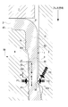
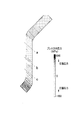
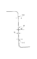
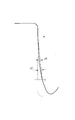
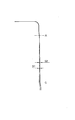
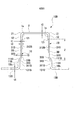
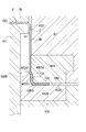
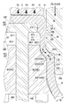
- FIG. 3 It is a partial perspective view of a member for vehicles (vehicles attachment state) of the 1st example concerning an embodiment of the present invention. It is sectional drawing of the member member for vehicles of 1st Example shown in FIG. It is a detailed sectional view concerning the 1st press-forming method which forms a thin part in the side wall part of the approximate hat cross-sectional shape of the member for vehicles shown in FIG. It is a schematic sectional drawing of the press type
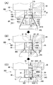
- FIG. 3 A cross-sectional view of the state is shown, (B) shows a cross-sectional view in the process of forming a thin-walled portion on a side wall portion of a substantially hat cross-sectional shape, (C) shows a cross-sectional view of a state where processing is completed at bottom dead center .
- FIG. 3 A cross-sectional drawing which concerns on the 1st press molding method shown in FIG. 3, and the modification of the 1st press type
- FIG. 6 It is a schematic sectional drawing of the press type
- a cross-sectional view of the state is shown, (B) shows a cross-sectional view in the process of forming a thin-walled portion on a side wall portion of a substantially hat cross-sectional shape, (C) shows a cross-sectional view of a state where processing is completed at bottom dead center .
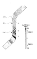
- It is a stress distribution figure (CAE analysis result) of the press direction at the time of a bottom dead center when the member parts for vehicles of the 1st example are fabricated using the 1st press type shown in Drawing 4, and it is plate outside Shows the stress distribution map in It is a stress distribution map (CAE analysis result) in the press direction at the bottom dead center when the present vehicle member part of the first embodiment is molded using the first press die shown in FIG.
- FIG. 6 is a cross-sectional view showing the amount of spring back and the amount of warpage when there is no flange portion at the front end portion of the side wall portion of the present vehicle member member of the first embodiment, when pressed by the first press die shown in FIG.
- FIG. 16 is a detailed cross-sectional view related to a fourth press-forming method of forming a thin-walled portion on a side wall portion having a substantially hat cross-sectional shape of the vehicle member component shown in FIG.
- FIG. 17C shows a detailed cross-sectional view of a portion Q shown in FIG. It is sectional drawing of the modification in the 4th press type
- FIG. 18 is a stress distribution diagram (CAE analysis result) in the press direction at the bottom dead center when the present vehicle member part of the second embodiment is molded using the fourth press die shown in FIG. Shows the stress distribution map in FIG.
- FIG. 18 is a stress distribution diagram (CAE analysis result) in the pressing direction at the bottom dead center when the present vehicle member part of the second embodiment is molded using the fourth press die shown in FIG. Shows the stress distribution map in It is sectional drawing showing the amount of springbacks of the side wall part of the member member for vehicles for this 2nd example, and the amount of curvature, and shows the case where it presses with the 4th press type shown in FIG.
- FIG. 17 is a detailed cross sectional view according to a modification of the fourth press molding method shown in FIG. 16; It is a cross-sectional schematic diagram which shows the principal part of the press die (compression force provision apparatus) described in patent document 1.
- FIG. It is a manufacturing-process figure of the vehicle components (hood for vehicles) described in patent document 2.
- FIG. It is principal part sectional drawing of the vehicle components (hood for vehicles) shown in FIG.
- results of CAE analysis of the amount of spring back and the amount of warpage in the side wall portion of the vehicle member component will be described in comparison with the case of bending according to the conventional method.
- mold to be used is demonstrated.
- results of CAE analysis of stress distribution in the vehicle part component of the second embodiment after press working, and results of CAE analysis of the amount of spring back and amount of warpage in the side wall portion will be described.
- mold is demonstrated.
- FIG. 1 shows a partial perspective view of a vehicle member part (vehicle mounted state) according to a first example of the embodiment of the present invention.
- FIG. 2 shows a cross-sectional view of the vehicle member component of the first embodiment shown in FIG.
- the up, down, left, right, front and rear direction arrows shown in FIG. 1 indicate the up, down, left, right, front, and rear directions in a state where the vehicle member component is attached to the vehicle.
- the vehicle member part 10 of the first example according to the present embodiment is formed by pressing a steel plate having a substantially uniform thickness and standing on the central portion 2 and the side walls standing up on the left and right sides thereof.
- a member member for a vehicle formed in a substantially hat cross-sectional shape including the portion 1, and the side wall portion 1 is formed at a first inner end edge of the base end portion 12 bent from the left and right ends of the central portion 2;
- An in-plate displacement surface 31 formed by displacement of the inner surface 1a from the stepped portion 121 to the distal end portion 11 substantially parallel to the plate outer side, and a base end from the second stepped portion 111 formed on the outer edge of the distal end portion 11
- the plate outer surface 1b is formed with the plate outer displacement surface 32 formed by being displaced substantially parallel to the plate inner side up to the portion 12, and the in-plate displacement surface 31 and the plate outer displacement surface 32
- a thin-walled portion 3 thinner than the thickness t0 of the central portion 2 is formed up to the portion 111 There.
- the first step portion 121 and the second step portion 111 are formed to have a thickness that changes in an inclined or arc shape.
- the thickness t0 of the central portion 2 is substantially the same as the thickness t0 of the steel plate W with almost no change in thickness due to bending.
- the vehicle member part 10 can be formed in which the thickness t3 of the thin portion 3 is 1.6 mm.
- the tensile strength and thickness of the steel plate W and the thickness of the thin portion are not limited to the above.
- a flange portion 13 thicker than the thin portion 3 and having a plate thickness t 4 is extended to the outside of the plate.
- the front end portion 11 is formed in an L shape including the flange portion 13, and the flange portion 13 is joined to the floor component 20 of the vehicle body S, for example, as shown in FIG.
- the flange portion 13 is joined to the floor part 20 of the vehicle body S to form a rectangular box cross section which is long in the vertical direction of the vehicle.
- the member member 10 for vehicles is arrange
- the central portion 2 and its shoulder R portion 21 which require a thick plate to contribute in terms of strength and rigidity of the vehicle
- the displacement t1 of the in-plate displacement surface 31 relative to the plate inner surface 1a and the displacement t2 of the out-of-plate displacement surface 32 relative to the plate outer surface 1b are formed by joining the steel plate thickness, tensile strength, floor parts, etc. Although it can set arbitrarily according to the section coefficient etc. of a box cross section, it is preferable that both (t1, t2) are the same. However, the above "identical” means substantially the same, and includes, for example, differences to some extent in terms of strength and rigidity.
- FIG. 2 shows a cross-sectional view of the vehicle member component of the first embodiment shown in FIG.
- FIG. 3 is a detailed cross-sectional view of a first press-forming method for forming a thin-walled portion on the side wall portion of the substantially hat cross-sectional shape of the vehicle member component shown in FIG.
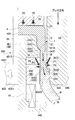
- FIG. 4 is a schematic cross-sectional view of a press die (first press die) used in the first press-forming method shown in FIG. 3;
- FIG. 5 shows a detailed cross-sectional view of the first press-forming method shown in FIG. 3 and a modification of the first press die shown in FIG.
- FIG. 6 is a detailed cross-sectional view of a second press-forming method for forming a thin-walled portion on the side wall portion of the substantially hat cross-sectional shape of the vehicle member component shown in FIG.
- FIG. 7 is a schematic cross-sectional view of a press die (second press die) used for the second press-forming method shown in FIG.
- FIG. 8 is a detailed cross-sectional view of a third press-forming method for forming a thin-walled portion on the side wall portion of the substantially hat cross-sectional shape of the vehicle member component shown in FIG.
- FIG. 9 is a schematic cross-sectional view of a press die (third press die) used in the third press-forming method shown in FIG.
- (B) shows a cross-sectional view in the process of forming a thin-walled portion on a side wall portion of a substantially hat cross-sectional shape
- (C) shows a state in which processing is completed at bottom dead center The cross section is shown.
- the steel plate W is bent at the shoulder R portion 21 of the central portion 2 using the first press die 30. After forming the base end 12 of the side wall 1, the steel plate W is squeezed in the press direction while being crushed in the thickness direction between the first step 121 and the second step 111. Finally, the thin portion 3 is formed, and a steel plate is finally bent to form the tip portion. According to the first press forming method, the thickness of the steel plate W can be reduced while promoting plastic flow of the steel plate W between the first step portion 121 and the second step portion 111 in the side wall portion 1 .
- the residual stress in the thin portion 3 can be made substantially uniform by the plastic flow of the steel plate W, and the amount of spring back, the amount of warpage, etc. in the side wall portion 1 having a substantially hat cross section can be reduced. Further, since the thin portion 3 is formed by squeezing and processing in the press direction while crushing the steel plate W in the thickness direction between the first step portion 121 and the second step portion 111, the wall of the thin portion 3 is formed. There is no fear that buckling deformation or the like in the height direction (pressing direction) occurs, but rather, the material length in the wall height direction of the thin-walled part 3 becomes longer with plastic flow, and the material width can be reduced The shortening effect can be achieved.
- the first press mold 30 includes a lower mold punch 4 having a substantially hat cross sectional shape, an upper mold 6 in which a bending blade 5 is formed opposite to the side wall of the lower mold punch 4, and And the upper pad 7 for pressing the steel plate W to the upper end portion 43 of the lower punch 4 before the bending blade 5 abuts on the steel plate W.
- a pressure member (elastic member or gas unit or the like) 71 that causes the upper pad 7 to generate a pressing force is attached to the upper mold 6.
- the side wall of the lower punch 4 is in contact with the upper side wall 41 crossing the upper end 43 and in contact with the plate inner surface 1 a of the base end 12 and the in-plate displacement surface 31 at the lower and outer sides of the upper side wall 41.
- a lower side wall 51 is formed on the side wall of the bending blade 5 that intersects the lower end 54 of the bending blade 5 and abuts on the plate outer surface 1 b of the distal end 11.
- a second convex portion 52 is formed in contact with the out-of-plate displacement surface 32 at the upper and inner side of 51.
- a mold clearance about the same as the thickness t 0 of the steel plate W is formed between the upper side wall portion 41 of the lower punch 4 and the lower side wall portion 51 of the bending blade 5.
- first convex portion 42 is formed so as to protrude to the plate outer side substantially in parallel to the upper side wall portion 41 of the lower punch 4.
- the upper end 421 of the first convex portion 42 is formed at a position corresponding to the first step portion 121 of the vehicle member part 10 as an inclined surface which is inclined by about 40 to 50 degrees with respect to the vertical surface.
- the second convex portion 52 is formed so as to protrude inward to the plate substantially in parallel to the lower side wall portion 51 of the bending blade 5.
- the lower end 523 of the second convex portion 52 is formed as a substantially arc-shaped surface at a position corresponding to the second step portion 111 of the vehicle member part 10.
- An oil groove 522 is formed between the lower end 523 of the second protrusion 52 and the lower side wall 51 of the bending blade 5.
- the present vehicle member part 10 is press-formed as follows. That is, first, as shown in FIG. 4A, a flat steel plate W is placed on the upper end portion 43 of the lower punch 4 and then the upper die 6 is lowered, and the upper pad 7 lowers the steel plate W.
- the die R portion 53 of the bending blade 5 bends the steel plate W at the shoulder R portion 21 of the central portion 2 in a state of being pressed against the upper end portion 43 of the punch 4.
- a flank 441 is formed on the pedestal 44 on which the lower punch 4 stands, in order to reduce the amount of warpage of the side wall 1 when the steel plate W is bent.
- the die R portion 53 of the bending blade 5 bends the steel plate W at the shoulder R portion 21 of the central portion 2 to form the base end portion 12. Then, the upper die 6 is further lowered.
- the second convex portion 52 of the bending blade 5 becomes substantially the same height as the first convex portion 42 of the lower punch 4, first, the upper end 421 of the first convex portion 42 presses the steel plate W to make the base end 12
- the first step portion 121 is formed at the inner and outer edges of the plate. Thereafter, the narrowing pressures P1 and P2 in the plate thickness direction against the steel plate W significantly increase, and the surface pressure reaches the area of cold forging.
- the second convex portion 52 of the bending blade 5 and the first convex portion 42 of the lower punch 4 narrowly press the steel plate W with the narrowing pressures P1 and P2 of the cold forging, thereby the first step portion 121 to the second step.
- the steel plate W is crushed and processed in the plate thickness direction up to the step portion 111.
- the downward squeezing force P3 by the 2nd convex part 52 with respect to the steel plate W will promote the plastic flow of the steel plate W to the wall height direction (press direction) of the side wall part 1. As shown in FIG.
- the upper pad 7 presses the steel plate W against the upper end portion 43 of the lower punch 4 with a predetermined pressing force P0, and the first step portion 121 of the vehicle component 10 as a wedge by the upper end 421 of the first convex portion 42 Since it is formed, the inflow of material from the central end 2 and the proximal end 12 side of the side wall 1 of the substantially hat cross sectional shape is inhibited. Therefore, as the second convex portion 52 of the bending blade 5 moves downward from substantially the same height as the first convex portion 42 of the lower punch 4, the material of the side wall portion 1 having a substantially hat cross sectional shape is pushed downward. The thin portion 3 is formed below the first step portion 121.
- the thin-walled portion 3 is formed by promoting plastic flow of the steel plate W in the wall height direction, residual stress in the wall height direction (pressing direction) of the thin-walled portion 3 causes a thickness difference. It can be greatly reduced compared to the conventional bending process which is not caused.
- a second step is formed at the boundary between the thin-walled portion 3 and the tip portion 11 of the vehicle member part 10 by pressing the plate outer edge of the tip portion 11 to the lower end 523 of the second convex portion 52 of the bending blade 5.
- the portion 111 is formed.
- the thickness t3 of the thin portion 3 is reduced by about 35 to 45% with respect to the thickness t0 of the central portion 2, the plastic flow of the steel plate W can be promoted more uniformly. Therefore, the difference in residual stress between the plate inner side and the plate outer side in the thin-walled portion 3 can be further reduced. As a result, it is possible to further reduce the spring back, the warpage, and the like in the side wall portion 1 having a substantially hat cross-sectional shape.
- the reduction rate of the thickness t3 of the thin portion 3 with respect to the thickness t0 of the central portion 2 is, for example, about 20%, as shown in FIG. It is preferable to form on the surface of the first convex portion 42 of the lower punch 4 a micro uneven pattern 422 continuous in the vertical direction.
- the in-plate displacement surface 31 of the thin-walled portion 3 can be extended in the vertical direction by the waveform 422 of the first convex portion 42. Therefore, even when the reduction rate of the thickness t3 of the thin portion 3 is small and compressive stress remains inside the steel plate W, tensile stress is applied to the in-plate displacement surface 31 of the thin portion 3 by the wave pattern 422 and compression is performed.
- the stress can be canceled to reduce the difference in residual stress in and out of the plate.
- the wave pattern 422 preferably has a depth d1 of about 0.3 to 0.5 mm and a pitch d2 of about 2 to 4 mm, for example.
- the second convex portion 52 of the bending blade 5 has the lower end 523 formed as a substantially arc-shaped surface at a position corresponding to the second step portion 111 of the vehicle member part 10.
- the upper portion 52 is preferably formed as a relief surface 521 slightly displaced to the outside of the plate. By forming the relief surface 521, it is possible to reduce friction with the steel plate W to prevent a mold damage and to reduce residual stress on the outer side of the thin portion 3 in the plate.
- the second press forming method of the vehicle member part 10 uses, for example, the second press die 30B to make the steel plate W a shoulder R portion of the central portion 2 After the base end 12 of the side wall 1 is formed by bending at 21, the steel plate W is narrowed in the thickness direction and crushed between the first step 121 and the second step 111, while being pressed In this method, the thin portion 3 is formed by squeezing in the direction, and finally the steel plate W is bent to form the tip portion 11.
- the processing principle of the second press-forming method is basically the same as the first press-forming method described above.
- a lower die punch 4B having a substantially hat cross-sectional shape, an upper die 6B in which a bending blade 5B is formed facing a side wall of the lower die punch 4B, and the upper die 6B.
- An upper pad 7B is provided to press the steel plate W against the upper end 43B of the lower punch 4B before the bending blade 5B is suspended and abuts on the steel plate W.
- a pressure member (elastic member or pressure unit or the like) 71B that causes the upper pad 7B to generate a pressing force is attached to the upper mold 6B.
- a flank surface 441B is formed on the pedestal portion 44B of the lower punch 4B in order to reduce the amount of warpage of the side wall portion 1 when the steel plate W is bent and processed.
- the lower punch 4B is composed of a punch upper portion 4B1 integrally formed with the pedestal portion 44B and a punch lower portion 4B2 formed so as to be separated from the punch upper portion 4B1 in the press direction (downward direction).
- the first convex portion 42B forming the in-plate displacement surface 31 of 10 is divided into an upper convex portion 42B1 formed in the lower side wall of the punch upper portion 4B1 and a lower convex portion 42B2 formed in the upper side wall of the punch lower portion 4B2. It is formed.
- an upper side wall portion 41B1 which intersects the upper end portion 43B and contacts the plate inner surface 1a of the base end portion 12 is formed.
- the punch lower portion 4B2 moves downward in synchronization with the lowering operation of the upper mold 6B from the time the upper mold 6B descends to a position where the second convex portion 52B and the lower convex portion 42B2 become substantially the same height. It is formed to be.
- a mold clearance of about the same as the thickness t0 of the steel plate W is formed.
- the upper convex portion 42B1 is formed so as to protrude to the plate outer side substantially in parallel to the upper side wall portion 41B1 of the punch upper portion 4B1.
- An upper end 42B11 of the upper convex portion 42B1 is formed at a position corresponding to the first step portion 121 of the vehicle member part 10 as an inclined surface which is inclined by about 40 to 50 degrees with respect to the vertical surface.
- the lower convex portion 42B2 is formed in a circular arc shape protruding outward from the plate on the upper side wall of the punch lower portion 4B2. At the lower part of the lower convex portion 42B2, a relief surface 42B22 slightly offset to the inner side of the lower convex portion 42B2 is formed.
- the amount of displacement of the in-plate displacement surface 31 by the lower convex portion 42B2 can be adjusted by adjusting the amount of displacement of the relief surface 42B22 relative to the lower convex portion 42B2.
- the second convex portion 52B is formed so as to protrude in an arc shape to the inside of the plate with respect to the lower side wall portion 51B of the bending blade 5B.
- the lower end of the second convex portion 52 ⁇ / b> B is formed at a position corresponding to the second step portion 111 of the vehicle member part 10.
- a flank surface 521B slightly parallel to the plate outer side with respect to the second convex portion 52B is formed on the upper portion of the second convex portion 52B, and the lower end of the second convex portion 52B and the lower side wall of the bending blade 5B
- An oil groove 522B is formed between the portion 51B.
- a synchronization member 61 is attached which contacts the 4B 21 and synchronously lowers the second convex portion 52B of the bending blade 5B and the lower convex portion 42B2 of the punch lower portion 4B2.
- a pressure member (elastic member or pressure unit or the like) 45 for biasing the punch lower portion 4B2 upward is attached between the lower end surface 4B23 of the punch lower portion 4B2 and the pedestal portion 44B.
- the upper pad 7B presses the steel plate W against the upper end 43B of the punch upper portion 4B1.
- the upper convex portion 42B1 and the second convex portion from the middle of press processing 52B narrows and squeezes the steel plate W in the thickness direction while the second convex portion 52B squeezes in the press direction to form the upper portion (a part of the thin portion 3 in the side wall portion 1 having a substantially hat cross-sectional shape ) 3a is formed, and further, the lower convex portion 42B2 and the second convex portion 52B squeeze each of the steel plate W in the press direction while narrowing and crushing the steel plate W in the thickness direction, thereby forming a substantially hat cross section Thin-walled part
- the reduction rate of the thickness t3 of the thin portion 3 with respect to the thickness t0 of the central portion 2 (steel plate) is small and the amount of each processing is small, the residual stress inside the plate of the thin portion 3 and the residual stress outside the plate
- the stress is substantially the same as the stress and hardly causes a difference, so that the amount of spring back, the amount of warpage, and the like in the side wall portion 1 having a substantially hat cross-sectional shape can be further reduced.
- the upper die 6B is lowered to move the upper pad 7B to the punch upper portion of the steel plate W.
- the die R portion 53B of the bending blade 5B bends the steel plate W at the shoulder R portion 21 of the central portion 2 in a state of being pressed against the upper end portion 43B of 4B1.
- the synchronization member 61 is not in contact with the lower punch portion 4B2. Therefore, the upper end surface 4B21 of the punch lower portion 4B2 is in contact with the lower end surface 4B11 of the punch upper portion 4B1.
- the die R portion 53B of the bending blade 5B bends the steel plate W at the shoulder R portion 21 of the central portion 2 to form the base end 12 and the first step.
- the upper die 6B is further lowered from the state where the part 121 and the part 121 are formed.
- the first step portion 121 is formed by the upper end 42B11 of the upper convex portion 42B1.
- the second convex portion 52B of the bending blade 5B and the upper convex portion 42B1 of the punch upper portion 4B1 narrow the steel plate W by the surface pressure of cold forging, so that the steel plate W in the thickness direction below the base end portion 12 Smashed into Then, a downward squeezing force P7 of the second convex portion 52B promotes plastic flow in the wall height direction (pressing direction) of the steel plate W to form the upper portion (a part) 3a of the thin portion 3.
- the squeezing force P6 to the lower side of the lower convex portion 42B2 of the punch lower portion 4B2 and the squeezing force P7 to the lower side of the second convex portion 52B of the bending blade 5B are in the wall height direction of the crushed steel plate W ( The plastic flow toward the pressing direction is promoted to form the lower portion (remaining portion) 3b of the thin portion 3.
- the lower end portion 54B of the bending blade 5B is placed on the steel plate W on the pedestal 44B of the lower punch 4B.
- the end face 442 B is pressed.
- a flange portion 13 thicker than the thin portion 3 is extended to the outside of the end portion 11 of the side wall portion 1 having a substantially hat cross sectional shape, and the vehicle member part 10 of the first embodiment is obtained. It is formed.
- the 2nd level difference part 111 of member member 10 for vehicles is formed of the lower end of the 2nd convex part 52B of bending blade 5B.
- the steel plate W is bent at the shoulder R portion 21 of the central portion 2 using the third press die 30C.
- the steel plate W is squeezed and crushed in the thickness direction between the first step portion 121 and the second step portion 111 and squeezed in the press direction
- the thin wall portion 3 is formed in the side wall portion 1 by processing, and finally the steel plate is bent to form the tip end portion 11.
- the processing principle of the third press forming method is the same as the first and second press forming methods described above.
- a lower die punch 4C having a substantially hat cross-sectional shape, an upper die 6C having a bending blade 5C formed opposite to a side wall of the lower die punch 4C, and a lower die 6C
- the upper edge portion 43C of the lower punch 4C is provided with an upper pad 7C for pressing the steel plate W before the bending blade 5C abuts on the steel plate W.
- a pressure member (elastic member or pressure unit or the like) 71C that causes the upper pad 7C to generate a pressing force is attached to the upper mold 6C.
- the lower punch 4C includes a punch upper portion 4C1 integrally formed with the pedestal portion 44C, and a punch lower portion 4C2 formed to be separable from the punch upper portion 4C1 in the press direction (downward direction).
- a first convex portion 42C in contact with the in-plate displacement surface 31 of 10 is formed on the upper side wall of the punch lower portion 4B2.
- an upper side wall portion 41B1 which intersects the upper end portion 43B and contacts the plate inner surface 1a of the base end portion 12 is formed.
- the lower part 4C2 of the punch since the lower part 4C2 of the punch lowers to a position where the second convex part 52C and the first convex part 42C become substantially the same height, it goes downward in synchronization with the lowering operation of the upper mold 6C. It is formed to move.
- a mold clearance approximately equal to the thickness t0 of the steel plate W is formed.
- the upper end 42C1 of the first convex portion 42C is formed at a position corresponding to the first step portion 121 of the vehicle member part 10 as an inclined surface which is inclined by about 40 to 50 degrees with respect to the vertical surface.
- the first convex portion 42C is formed in an arc shape protruding outward from the plate on the upper side wall of the punch lower portion 4B2.
- a relief surface 42C2 which is slightly parallel to the inner side of the first convex portion 42C is formed.
- the second convex portion 52C is formed so as to protrude in an arc shape to the inside of the plate with respect to the lower side wall portion 51C of the bending blade 5C.
- the lower end of the second convex portion 52 ⁇ / b> C is formed at a position corresponding to the second step portion 111 of the vehicle member part 10.
- An upper surface of the second convex portion 52C is formed with a flank 521C slightly parallel to the plate outer side with respect to the second convex portion 52C, and a lower end of the second convex portion 52C and a lower side wall of the bending blade 5C.
- An oil groove 522C is formed between the portion 51C.
- the upper portion of the punch lower portion 4C2 A synchronization member 61 is attached which contacts the end face 4C21 and lowers the second convex portion 52C of the bending blade 5C and the first convex portion 42C of the punch lower portion 4C2 synchronously.
- a pressure member a cushioned pin with a lock or a pressure unit with a lock or the like
- 45C for pressing the punch lower portion 4C2 upward is in contact with the lower end surface 4C23 of the punch lower portion 4C2.
- the punch lower portion 4C2 is formed to face the lower end portion 54C of the bending blade 5C.
- the upper pad 7C presses the steel plate W against the upper end 43C of the punch upper portion 4C1. Then, after the bending blade 5C of the upper die 6C bends the steel plate W to form the base end 12 along the upper side wall 41C1 of the punch upper portion 4C1, the first convex portion 42C and the second convex are started from the middle of bending
- the thin portion 3 can be formed on the side wall portion 1 having a substantially hat cross-sectional shape by squeezing and processing in the press direction while the portion 52C squeezes by narrowing the steel plate W in the thickness direction.
- the steel plate W is pressed by the crease pressing portion 4C22 of the punch lower portion 4C2 and bent by the die R portion 53C of the bending blade 5C and further bent back along the lower side wall portion 51C of the bending blade 5C.
- the first convex portion 42C and the second convex portion 52C squeeze the sheet in the thickness direction and squeeze the sheet in the press direction. Therefore, the steel plate W whose thickness is reduced through bending and bending back processing may be squeezed in the press direction while being crushed in the thickness direction by the first convex portion 42C and the second convex portion 52C. it can. Therefore, the thin portion 3 can be formed on the side wall portion 1 having a substantially hat cross-sectional shape with less mold load.
- the second convex portion 52C and the first convex portion 42C move downward in synchronization with the lowering operation of the upper mold 6C from the time the upper mold 6C is lowered to a position where the second convex portion 52C and the first convex portion 42C have substantially the same height.
- the tensile stress generated inside the plate of the thin portion 3 by squeezing the first convex portion 42C and the tensile stress generated outside the plate of the thin portion 3 by squeezing the second convex portion 52C Will remain the same extent.
- the upper die 6C is lowered to move the upper pad 7C to the punch upper portion
- the die R portion 53C of the bending blade 5C bends the steel plate W at the shoulder R portion 21 of the central portion 2 in a state of being pressed to the upper end portion 43C of 4C1.
- the synchronization member 61 is not in contact with the punch lower portion 4C2. Therefore, the upper end surface 4C21 of the punch lower portion 4C2 is in contact with the lower end surface 4C11 of the punch upper portion 4C1.
- the die R portion 53C of the bending blade 5C bends the steel plate W at the shoulder R portion 21 of the central portion 2 to form the base end portion 12 and the first step.
- the upper die 6C is further lowered from the state where the portion 121 and the portion 121 are formed.
- the first step portion 121 is formed by sandwiching the steel plate W with the upper end 42C1 of the first convex portion 42C and the second convex portion 52 of the bending blade 5C.
- the upper end 42C1 of the first convex portion 42C is formed as an inclined surface which is inclined by about 40 to 50 degrees with respect to the vertical surface, so that the thrust load in the mold opening direction (lateral direction) with respect to the bending blade 5C can be reduced.
- the narrowing pressures P4 and P5 against the steel plate W in the thickness direction significantly increase.
- the pressure reaches the area of cold forging. That is, when the second convex portion 52C of the bending blade 5C and the first convex portion 42C of the punch lower portion 4C1 press the steel plate W with a surface pressure of cold forging, between the base end 12 and the tip 11 The steel plate W is crushed in the thickness direction.
- the synchronization member 61 abuts on the upper end surface 4C21 of the punch lower portion 4C2.
- the second convex portion 52C of the bending blade 5C and the first convex portion 42C of the punch lower portion 4C2 are synchronously lowered.
- the pressing force of the pressing member 45C acts upward on the punch lower portion 4C2.
- the steel plate W is pressed by the crease pressing portion 4C22 of the punch lower portion 4C2 and bent by the die R portion 53C of the bending blade 5C, and further bent back along the lower side wall 51C of the bending blade 5C to reduce After being made thick, it is crushed in the thickness direction by the first convex portion 42C and the second convex portion 52C, and is wrought in the press direction.
- the downward handle force P6 of the first convex portion 42C of the punch lower portion 4C2 and the lower handle force P7 of the second convex portion 52C of the bending blade 5C are crushed in the wall height direction of the steel plate W ( By promoting plastic flow in the pressing direction, the thin portion 3 is formed between the first step portion 121 and the second step portion 111.
- the tensile stress generated in the press direction on the inner side of the thin portion 3 by squeezing the first convex portion 42C and the tensile stress generated in the press direction on the outer side of the thin portion 3 by squeezing the second convex portion 52C. Will remain on the thin portion 3 at the same level.
- the reduction rate of the plate thickness t3 of the thin portion 3 is small, the same tensile stress can be applied to the in-plate displacement surface 31 and the out-of-plate displacement surface 32 of the thin portion 3. Therefore, a difference in residual stress between the inside and outside of the thin portion 3 can be reduced, and spring back, warpage, and the like in the side wall portion 1 having a substantially hat cross-sectional shape can be reduced.
- the gap between the crease holding portion 4C22 of the punch lower portion 4C2 and the lower end portion 54C of the bending blade 5C can be adjusted by the height of the synchronization member 61.
- the synchronization member 61 may be installed between the crease pressing portion 4C22 and the lower end portion 54C of the bending blade 5C. Also, when the upper die 6C rises after passing the bottom dead center, the pressing member 45C is temporarily locked to delay the rise timing of the punch lower portion 4C2. This prevents deformation of the pressed vehicle member part.
- FIGS. 10A and 10B are compared with the case where bending is performed according to the conventional method in which no difference in plate thickness occurs. It demonstrates using FIG. 11A and FIG. 11B.
- FIG. 10A is a stress distribution diagram (CAE analysis result) in the press direction at the bottom dead center when the present vehicle member part of the first embodiment is molded using the first press die shown in FIG. 4. Show the stress distribution on the outside of the plate.
- FIG. 10B is a stress distribution diagram (CAE analysis result) in the press direction at the bottom dead center when the present vehicle member part of the first embodiment is molded using the first press die shown in FIG. 4.
- FIG. 11A Show the stress distribution inside the plate.
- FIG. 11B Stress at the bottom dead center when molding a vehicle member part of the same material and size as the vehicle member part of the first embodiment using the conventional press die that does not cause a thickness difference is used.
- FIG. 11B Stress at the bottom dead center when molding a vehicle member part of the same material and size as the vehicle member part of the first embodiment using the conventional press die that does not cause a thickness difference is used.
- FIG. 11B Show the stress distribution map in a board inner side is shown.
- the thickness t3 of the thin portion 3 in the vehicle member part 10 shown in FIGS. 10A and 10B is 1.6 mm.
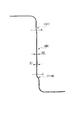
- the stress distribution in the pressing direction on the plate outer side of the thin-walled portion 3 formed on the side wall portion having a substantially hat cross-sectional shape has a tensile stress of about 600 MPa at a position A adjacent to the first step portion 121. And a tensile stress of about 800 Mpa is generated at a position B which is an intermediate point between the first stepped portion 121 and the second stepped portion 111, and a tensile stress of about 900 Mpa is generated at a position C adjacent to the second stepped portion 111. It is happening. Further, as shown in FIG.
- the stress distribution in the pressing direction on the inner side of the thin portion 3 formed on the side wall portion having a substantially hat cross sectional shape is about 500 Mpa at the position A adjacent to the first step portion 121.
- a tensile stress is generated, and a tensile stress of about 500 Mpa is generated at a position B which is an intermediate point between the first stepped portion 121 and the second stepped portion 111, and a tensile stress of about 400 Mpa is generated at a position C adjacent to the second stepped portion 111.
- the state of stress distribution in the pressing direction on the plate outside of the side wall portion having a substantially hat cross sectional shape that does not cause a plate thickness difference is about 700 Mpa at position a corresponding to position A.
- a tensile stress is generated, and at a position b corresponding to the position B, a tensile stress of approximately 500 Mpa is generated, and at a position c corresponding to the position C, a tensile stress of approximately 100 Mpa is generated.
- FIG. 11A the state of stress distribution in the pressing direction on the plate outside of the side wall portion having a substantially hat cross sectional shape that does not cause a plate thickness difference is about 700 Mpa at position a corresponding to position A.
- a tensile stress is generated, and at a position b corresponding to the position B, a tensile stress of approximately 500 Mpa is generated, and at a position c corresponding to the position C, a tensile stress of approximately 100 Mpa is generated.
- the stress distribution in the pressing direction on the inner side of the side wall portion of the substantially hat cross sectional shape that does not cause a thickness difference is about 300 MPa of compressive stress at position a corresponding to position A.
- a compressive stress of about 100 Mpa is generated
- a tensile stress of about 100 Mpa is generated.
- the plates at positions A to B in which the springback amount of the side wall portion in the substantially hat cross section is easily affected While the stress difference between the outside and the inside of the plate is about 100 to 300 Mpa, in the case of a conventional vehicle member part having no difference in plate thickness, as shown in FIG. 11A and FIG.
- the stress difference between the outer side and the inner side of the plate at positions a to b that easily affect the amount of springback of the side wall portion was about 600 to 1000 Mpa.
- the position A and the position C of the outer side of the plate which easily affect the amount of warpage of the side wall portion in the substantially hat cross sectional shape. While the stress difference was about 300 Mpa, in the case of a conventional vehicle member component that does not have a difference in plate thickness, as shown in FIG. The stress difference between position a and position c was about 600 Mpa.
- FIG. 12A is a cross-sectional view showing the amount of spring back and the amount of warpage of the side wall portion of the member member for a vehicle of the first embodiment, and shows the case of pressing with the first press die shown in FIG. FIG.
- FIG. 12B is a cross-sectional view showing the amount of springback and the amount of warpage of the side wall portion of a conventional vehicle member component, and shows the case of pressing with a conventional press die that does not cause a thickness difference.
- FIG. 13 is a cross-sectional view showing the amount of spring back and the amount of warpage when there is no flange at the front end of the side wall of the present vehicle member component of the first embodiment, and the first press die shown in FIG. Indicates the case of pressing with.
- the amount of springback of the thin portion 3 formed on the side wall portion having a substantially hat cross-sectional shape is a position C adjacent to the second step portion 111 starting from the position A adjacent to the first step portion 121.
- the angle S1 at which the plate opens to the outside of the plate is about 0.8 degrees.
- the amount of warpage of the thin portion 3 formed on the side wall portion having a substantially hat cross sectional shape is the first step portion starting from the position A adjacent to the first step portion 121 and the position C adjacent to the second step portion 111. It was about 0 mm when the largest displacement amount S2 was calculated in the middle point of 121 and the 2nd level
- the amount of springback of the side wall portion having a substantially hat cross-sectional shape that does not cause a thickness difference is the position c corresponding to the position C starting from the position a corresponding to the position A It was about 5 degrees when angle s1 which opens to the board outer side was computed. Further, the amount of warpage of the side wall portion having a substantially hat cross sectional shape is about 0.9 mm when the maximum displacement amount s2 is calculated at the middle point from the position a corresponding to the position A and the position c corresponding to the position C Met.
- FIG. 14 shows a partial perspective view of a vehicle member part (vehicle mounted state) of a second example according to the embodiment of the present invention.
- FIG. 15 shows a cross-sectional view of the vehicle member part of the second embodiment shown in FIG.
- the up, down, left, right, front and back direction arrows shown in FIG. 14 indicate the up, down, left, right, front and back directions in a state where the vehicle member component is attached to the vehicle.
- the vehicle member part 10B of the second example according to the present embodiment is formed by pressing a steel plate having a substantially uniform thickness and standing on the central portion 2 and the side walls standing up on the left and right sides thereof.
- In-plate displacement surface 31B formed by displacement of the plate inner surface 1a from the step portion 121 to the tip end portion 11B to the plate outer side, and from the second step portion 111B to the base end portion 12 formed at the plate outer edge of the tip end portion 11B
- the plate outer surface 1Bb is provided with a plate outer displacement surface 32B formed by being displaced inward to the plate inner side, and between the first step portion 121 and the second step portion 111B by the in-plate displacement surface 31B and the plate outer displacement surface 32B.
- the first step portion 121 and the second step portion 111B are formed to have a thickness that changes in an inclined or arc shape.
- the thickness t0 of the central portion 2 is substantially the same as the thickness t0 of the steel plate W with almost no change in thickness due to bending.
- the vehicle member part 10B in which the plate thickness t3 of the thin portion 3B is 1.6 mm can be formed.
- the tensile strength and thickness of the steel plate W and the thickness of the thin portion are not limited to the above.
- a flange portion 13B thicker than the thin-walled portion 3B and having a plate thickness t4 is extended to the outside of the plate at the tip end 11B of the side wall 1B.
- the tip end portion 11B is formed in an L shape including the flange portion 13B, and the flange portion 13B is joined to the floor component 20 of the vehicle body S, for example, as shown in FIG.
- the vehicle member part 10B is joined to the floor part 20 of the vehicle body S to form a rectangular box cross section which is long in the vertical direction of the vehicle.
- the vehicle member component 10B is disposed on both sides in the vehicle left-right direction of the vehicle body S, extends in the vehicle longitudinal direction (axial direction), and is configured as a framework member for securing the strength and rigidity of the vehicle.
- central portion 2 and its shoulder R 21 requiring a thick plate to contribute in terms of strength and rigidity of the vehicle
- a thin-walled portion 3B is formed in an intermediate zone Z in the wall height direction of the side wall portion 1B which can secure the strength and rigidity of the vehicle even if the thickness is reduced while leaving thick portions at the base end portion 12 ing.
- the intra-plate displacement surface 311B on the tip end side of the second step portion 111B is displaced to the outside of the plate from the intra-plate displacement surface 312B on the thin portion side.
- the displacement t1 of the in-plate displacement surface 31B of the first step portion 121 with respect to the plate inner surface 1a and the displacement t5 of the out-of-plate displacement surface 32B of the second step portion 111B with respect to the plate outer surface 1Bb are the thickness and tensile strength of the steel plate. It can be set arbitrarily according to the cross section coefficient etc. of the box cross section formed by being joined to the floor parts etc.
- the side wall in the second step portion 111B is formed by forming the displacement t5 larger than the displacement t1.
- the portion 1B is bent in a step-like manner, and bending lines 33B and 34B for shape freezing are formed on the side wall 1B.
- tip part 11B on either side is formed larger than the space
- the side wall portion 1B is bent stepwise only once in the second step portion 111B, but the side wall portion 1B may be bent stepwise in a plurality of times in the second step portion 111B.
- FIG. 15 shows a cross-sectional view of the vehicle member part of the second embodiment shown in FIG.
- FIG. 16 is a detailed cross-sectional view of a fourth press-forming method for forming a thin-walled portion on the side wall portion of the substantially hat cross-sectional shape of the vehicle member component shown in FIG.
- FIG. 17 is a cross-sectional view of a press die (fourth press die) used in the fourth press-forming method shown in FIG.
- FIG. 16 shows a steel plate at a shoulder R portion of a central portion of a substantially hat cross-sectional shape The cross-sectional view of the bent state is shown, (B) shows a cross-sectional view in the middle of forming the thin-walled portion on the side wall portion of the substantially hat cross-sectional shape, and (C) shows the cross-section in the processed state at bottom dead center Figure shows.
- FIG. 18 shows a detailed cross-sectional view of a portion Q shown in FIG. 17 (C).
- FIG. 19 shows a cross-sectional view of a modification of the fourth press die shown in FIG. 17 (C).
- the press forming method (fourth press forming method) of the vehicle member part 10B according to the second embodiment uses, for example, a fourth press die 30D to form a steel plate W Is bent at the shoulder R portion 21 of the central portion 2 of the substantially hat cross sectional shape to form the base end portion 12, then the steel plate W is crushed in the thickness direction at the first step portion 121 or stretched in the press direction At the same time, by bending back the steel plate W in the direction inclining with respect to the pressing direction in the second step portion 111B and further bending back in the pressing direction, the distance from the first step portion 121 to the second step portion 111B At the same time, the inner side and the outer side of the steel plate W are drawn in the same direction in the press direction to form the thin portion 3B, and at the same time the side wall 1B is bent stepwise in the second step 111B.
- B bending W to the tip 1B is a method of forming a
- the thickness can be reduced substantially uniformly to form the thin portion 3B. Therefore, in addition to the crushing process of the steel plate W, the thin-walled portion 3B can be formed without performing the rubbing process, and therefore, the mold load (scissors of the bending blade, mold opening, etc.) accompanying the forming of the thin-walled portion 3B can be significantly reduced.
- the difference in residual stress occurring between the plate inner side and the plate outer side in the thin portion 3B can be significantly reduced. That is, the tensile stress generated by the bending process is offset by the compressive stress generated by the bending process, and the residual stress in the plate inner side and the plate outer side in the thin portion 3B can be reduced to the same extent. Therefore, since the difference in residual stress generated between the plate inner side and the plate outer side in the thin portion 3B is small, it is possible to significantly reduce the amount of spring back, the amount of warpage, etc. in the side wall portion having a substantially hat cross section.
- a pressure member (elastic member or pressure unit or the like) 71D that causes the upper pad 7D to generate a pressing force is attached to the upper mold 6D.
- the lower punch 4D is composed of a punch upper portion 4D1 integrated with the pedestal portion 44D, and a punch lower portion 4D2 formed so as to be separated from the punch upper portion 4D1 in the press direction (downward direction). Further, a pressure member (a cushioning pin with locking or a pressing unit with locking or the like) 45D for pressing the punch lower portion 4D2 upward is in contact with the lower end surface 4D23 of the punch lower portion 4D2.
- an upper side wall portion 41D1 is formed which intersects the upper end portion 43D and abuts on the plate inner surface 1a of the base end portion 12.
- a first recess 42D2 that contacts or opposes the in-plate displacement surface 312B on the base end side and a plate displacement that protrudes to the plate outer side below the first recess 42D2 and is on the tip side
- the first inclined portion 42D3 may be linearly inclined or curved.
- the upper die 6C is lowered to a position where it is formed in the punch lower portion 4D2 so as to face the lower end portion 54D of the bending blade 5D and the first convex portion 42D1 and the second convex portion 52C become substantially the same height.
- the wrinkle control unit 4C22 is formed horizontally.
- the first convex portion 42D1 is formed to stand vertically to the wrinkle pressing portion 4D22 of the punch lower portion 4D2.
- the punch lower part 4D2 is formed by dividing left and right symmetrically with respect to the punch upper part 4D1, and the divided punch lower part 4D2 and the bending blade 5D facing the punch lower part 4D2 extend in the longitudinal direction of the hat cross sectional shape. It is guided along the same guide member 44D1 formed on the pedestal 44D. As a result, even when the side wall portion 1B of the vehicle member part 10B is extended largely in the longitudinal direction, the same type guide member 44D1 suppresses bending of the punch lower portion 4D2 and the bending blade 5D by the same guide member 44D.
- the clearance (bending clearance) can be maintained substantially constant.
- a lower side wall portion 51D intersecting with the lower end portion 54D of the bending blade 5D and the die R portion 53D and abutted or opposed to the plate outer surface 1Bb of the leading end portion 11B and the upper side of the lower side wall portion 51D
- a second convex portion 52D which protrudes inward to contact with the plate outer displacement surface 32B, and connects the lower sidewall portion 51D and the second convex portion 52D in an inclined manner to form a plate outer displacement surface 32B at the second step portion 111B.
- a second inclined portion 522D to be abutted is formed.
- the second inclined portion 522D is formed to be inclined at a position corresponding to the second step portion 111B of the vehicle member part 10B.
- the second inclined portion 522D may be linearly inclined or curved.
- an upper surface of the second convex portion 52D is formed with a flank surface 521D which is slightly displaced substantially in parallel to the plate outer side.
- a mold clearance approximately equal to the thickness t0 of the steel plate W is formed.
- the punch lower portion 4D2 moves downward in synchronization with the lowering operation of the upper mold 6D from the time the upper mold 6D descends to a position where the first concave portion 42D2 and the second convex portion 52D become substantially the same height. It is formed to be.
- the upper die 7D presses the steel plate W against the upper end 43D of the lower die punch 4D.
- the steel plate W is the punch lower portion 4D2.
- the sheet W is pressed by the wrinkle pressing portion 4D22 and bent by the die R 53D of the bending blade 5D, and is further bent back along the lower side wall 51D of the bending blade 5D to reduce the plate thickness t0.
- the plate thickness of the steel plate W gradually decreases while being bent again by the first inclined portion 42D3 and the second inclined portion 522D. Then, when passing the steel plate W whose thickness is reduced between the first concave portion 42D2 and the second convex portion 52D, the thin portion 3 having the required thickness t3 is formed by performing bending back processing again.
- the tip end 11B is formed at the press bottom dead center. Therefore, the base end portion 12, the thin portion 3 and the tip end portion 11B can be formed on the side wall portion 1B of the substantially hat cross sectional shape through bending and bending back processing from the steel plate W having a substantially uniform thickness t0. As a result, the load of the bending blade 5D or the like forming the thin portion 3 can be significantly reduced.
- the upper die 6D is lowered to move the upper pad 7D to the punch upper portion of the steel plate W.
- the die R portion 53D of the bending blade 5D bends the steel plate W at the shoulder R portion 21 of the flat portion 2 in a state of being pressed to the upper end portion 43D of 4D1.
- the upper end surface 4D21 of the punch lower portion 4D2 is in contact with the lower end surface 4D11 of the punch upper portion 4D1.
- the die R portion 53D of the bending blade 5D bends the steel plate W at the shoulder R portion 21 of the central portion 2 to form the base end 12 and the first step.
- the upper die 6D is further lowered from the state in which the portion 121 is formed.
- the first step portion 121 is formed by the upper end corner portion 42D21 of the first recess 42D2.
- the wrinkle pressing portion 4D22 lowers the steel plate W and the lower end portion of the bending blade 5D It is pressed along 54D to perform bending and bending back processing. Further, when the steel plate W passes through the first inclined portion 42D2 and the second inclined portion 522D, the steel sheet W is bent in a direction inclined to the pressing direction, and further passes through the first concave portion 42D2 and the second convex portion 52D. At the same time, the steel plate W is bent back in the press direction, the thickness of the steel plate W is gradually reduced, and the thin portion 3B is formed.
- the lower end portion 54D of the bending blade 5D applies the steel plate W to the crease pressing portion 4D22 of the punch lower portion 4D2. Press.
- a flange 13B thicker than the thin wall 3B is extended to the outside at the tip 11B of the side wall 1B having a substantially hat cross-sectional shape, and at the same time, the side wall 1B is formed by the second step 111B. It is bent in a step-like manner to form a vehicle member part 10B.
- the pressing member 45D is temporarily locked to delay the timing of ascent of the punch lower portion 4D2. This prevents deformation of the vehicle member part 10B.
- a distance block 62 is mounted between the punch lower portion 4D2 and the bending blade 5D to adjust the gap d3 between the crease holding portion 4D22 and the lower end portion 54D of the bending blade 5D.
- the distance block 62 adjusts the gap (type clearance) between the wrinkle holding portion 4D22 and the lower end portion 54D of the bending blade 5D to be larger than the thickness of the steel plate W, so that the pressure holding member 4D22 and the bending blade 5D Simple control of thickness reduction due to bending and bending back work in the steel plate W sandwiched between the lower end portion 54D and reduction of mold load (bending of bending blade, mold opening, etc.) accompanying bending work Can.
- the thickness t7 of the steel plate W bent again is reduced to 2.0 to 2.1 mm, and further, the punch lower portion 4D2
- the plate is again bent back and its plate thickness t3 is 1.4 to 1.2. The thickness is reduced to about 5 mm to form a thin portion 3B.
- the thin portion 3B having a desired thickness can be easily made. It can be formed.
- the bending and bending back mold clearances (d3, d4, d5) are formed larger than the thickness (t4, t6, t3) of the steel plate W passing through all. As a result, it is possible to significantly reduce the mold load (bent cutting of the bending blade, mold opening, etc.) involved in the bending process.
- the first recess 42D2 is formed vertically in parallel with the pressing direction, and the upper corner 42D21 thereof corresponds to the first step 121 of the vehicle member part 10B. At the position, it is formed as a circular arc surface.
- the first recess 42D22 is extended to the inside of the plate along the extension of the first inclined portion 42D3. It is preferable to form by making it incline. In this case, as shown in FIG. 19, the first step portion 121 is formed into an inclined shape by being stretched in the press direction without being crushed in the plate thickness direction, but the thrust when forming the first step portion 121 The load can be reduced significantly. As shown in FIG. 19, it is preferable that the steel block 5DD including the die R portion 53DD and the second convex portion 52DD be divided and attached to the bending blade 5D to perform surface treatment with high wear resistance. . In addition, it is preferable that the steel block 4DD2 including the first convex portion 42DD1, the first inclined portion 42DD3 and the first concave portion 42DD2 be divided and attached to the punch lower portion 4D2 to perform surface treatment with high wear resistance.
- FIG. 20 is a stress distribution diagram (CAE analysis result) in the press direction at the bottom dead center when the present vehicle member part of the second embodiment is molded using the fourth press die shown in FIG. 17. Show the stress distribution on the outside of the plate.
- FIG. 21 is a stress distribution diagram (CAE analysis result) in the press direction at the bottom dead center when the present vehicle member part of the second embodiment is molded using the fourth press die shown in FIG. 17. Show the stress distribution inside the plate.
- the thickness t3 of the thin-walled portion 3B in the vehicle member part 10B in FIGS. 20 and 21 is 1.4 mm.
- the stress distribution in the press direction on the plate outer side of the thin-walled portion 3B formed on the side wall portion having a substantially hat cross-sectional shape has a tensile stress of about 700 Mpa at the position A adjacent to the first step portion 121. And a tensile stress of about 970 Mpa occurs at position B, which is the middle point between the first step 121 and the second step 111B, and a tensile stress of about 1090 Mpa, occurs at the point C adjacent to the second step 111B. It is happening.
- FIG. 20 the stress distribution in the press direction on the plate outer side of the thin-walled portion 3B formed on the side wall portion having a substantially hat cross-sectional shape
- the stress distribution in the pressing direction on the inner side of the thin portion 3 formed in the side wall portion having a substantially hat cross sectional shape is about 850 MPa at the position A adjacent to the first step portion 121.
- a tensile stress is generated, and a tensile stress of approximately 1000 Mpa is generated at a position B which is an intermediate point between the first step portion 121 and the second step portion 111B, and a position of approximately 700 Mpa is generated at a position C adjacent to the second step portion 111B.
- the plates at positions A to B in which the springback amount of the side wall portion in the substantially hat cross sectional shape is easily affected The stress difference between the outside and the inside of the plate was about 150 to 30 Mpa.
- the springback amount of the side wall portion in the substantially hat cross sectional shape is easily affected.
- the stress difference between the plate outer side and the plate inner side at the positions a to b was about 600 to 1000 Mpa.
- the position A and the position C of the outside of the plate which easily affect the amount of warpage of the side wall portion in the substantially hat cross sectional shape.
- the stress difference was about 390 Mpa.
- the position of the plate outside easily affects the amount of warpage of the side wall portion in the substantially hat cross section.
- the stress difference between a and c was about 600 Mpa.
- the vehicle member component 10B of the second example according to the present embodiment is compared with the case where it is bent by the conventional method which does not cause a thickness difference.
- the stress difference that easily affects the amount of springback and the amount of warpage of the side wall in the substantially hat cross-sectional shape can be significantly reduced.
- FIG. 22 is a cross-sectional view showing the amount of spring back and the amount of warpage of the side wall portion of the member member for a vehicle of the second embodiment, and shows the case of pressing with the fourth press die shown in FIG.
- the springback amount of the thin portion 3B formed on the side wall portion having a substantially hat cross sectional shape is a position C adjacent to the second step portion 111B starting from the position A adjacent to the first step portion 121.
- the angle S1 at which the plate opens to the outside of the plate is about -0.5 degrees.
- the amount of warpage of the thin portion 3B formed on the side wall portion having a substantially hat cross-sectional shape is the first step portion starting from the position A adjacent to the first step portion 121 and the position C adjacent to the second step portion 111B. It was about 0 mm when the largest displacement amount S2 was calculated in the middle point of 121 and the 2nd level
- the springback amount of the side wall portion having a substantially hat cross sectional shape which does not cause a thickness difference starts from position a corresponding to position A, position C
- the angle s1 at which the position c corresponding to f1 opens to the outside of the plate is about 5 degrees.
- the amount of warpage of the side wall portion having a substantially hat cross sectional shape is about 0.9 mm when the maximum displacement amount s2 is calculated at the middle point from the position a corresponding to the position A and the position c corresponding to the position C Met.
- the side wall portions 1 and 1B are formed on the inner end edge of the base end portion 12 bent from the central portion 2 A second step formed on the plate outer end edge of the in-plate displacement surface 31, 31B formed by the plate inner surface 1a being displaced outward from the first step portion 121 to the tip portion 11, 11B and the tip portion 11, 11B.
- Plate outer displacement surfaces 32 and 32B formed by displacement of the plate outer surfaces 1b and 1Bb from the portions 111 and 111B to the base end portion 12 inward, and the in-plate displacement surfaces 31 and 31B and the plate outer displacement surfaces 32; Since the thin portions 3 and 3B having a thickness t3 thinner than the thickness t0 of the central portion 2 are formed between the first step portion 121 and the second step portions 111 and 111B by 32B, strength and rigidity of the vehicle Central part 2 and its thickness which is necessary to contribute The side wall portions 1 and 1B can ensure the strength and rigidity of the vehicle even if the thickness is reduced while leaving thick portions in the shoulder R portion 21 and the base end portion 12 and the front end portions 11B of the side wall portions 1 and 1B.
- the thin portions 3 and 3B can be formed in the middle area Z in the wall height direction (between the first step 121 and the second step 111 and 111B).
- the thin portions 3 and 3B in the side wall portions 1 and 1B are formed by pressing a steel plate W having a substantially uniform thickness t0. Therefore, in the vehicle component parts 10 and 10B, the high-tensification of the steel plate W and the partial thinning of the plate thickness can be easily realized without using a new process such as tailored blank welding and equipment. As a result, it is possible to easily achieve both of the reduction in weight and the increase in strength of the vehicle member component 10, 10B.
- the high steel sheet W and the partial thickness reduction of the steel plate W are realized in bending. It is possible to provide a vehicle part 10, 10B that can be
- the flange portions 13 and 13B having a plate thickness t4 larger than the thin portions 3 and 3B are provided at the end portions 11 and 11B of the side wall portions 1 and 1B.
- flanges 13 and 13B consisting of thick parts contributing a large proportion in the strength and rigidity of the vehicle can be formed on the front ends 11 and 11B of the side walls 1 and 1B, It is possible to make the weight reduction and the high strength in the vehicle member part 10, 10B more compatible with each other more easily.
- the displacement amount t1 with respect to the plate inner surface 1a of the in-plate displacement surface 31 and the displacement amount t2 with respect to the plate outer surface 1b of the plate outer displacement surface 32 are substantially the same. Because of this, it is possible to reduce the eccentric load that causes the thin-walled portion 3 to bend or buckle with respect to the load that acts in the vertical direction of the vehicle. Therefore, it is possible to increase the decreasing rate of the plate thickness t3 of the thin portion 3 with respect to the plate thickness t0 of the steel plate W while maintaining predetermined strength and rigidity, and to reduce weight and increase strength of the vehicle member part 10. It can be promoted more easily.
- the in-plate displacement surface 311B on the tip end side of the second step portion 111B is displaced outward from the in-plate displacement surface 312B on the thin portion side.
- the side wall portion 1B is bent in a step-like manner in the second step portion 111B to form the shape freezing folding lines 33B and 34B in the side wall portion 1B.
- interval of tip part 11B on either side can be formed larger than the space
- the steel plate W is bent at the shoulder R portion 21 of the central portion 2 to form the base end portion 12 of the side wall portion 1 while crushing the steel plate W in the thickness direction between the first step portion 121 and the second step portion 111, the thin portion 3 is formed by squeezing in the press direction, and finally the steel plate W is bent and processed. Since the front end portion 11 is formed, crushing and squeezing processing are performed between the first step portion 121 and the second step portion 111 in the bent side wall portion 1, and plastic flow of the steel plate W in the thin portion 3 The thickness can be reduced while being promoted.
- the residual stress in the thin portion 3 can be made uniform by the plastic flow of the steel plate W, and the amount of spring back, the amount of warpage, etc. in the side wall portion 1 having a substantially hat cross sectional shape based on bending can be reduced.
- the thin portion 3 is formed by squeezing and processing in the press direction while crushing the steel plate W in the thickness direction between the first step portion 121 and the second step portion 111, the wall of the thin portion 3 is formed. There is no fear that buckling deformation or the like in the height direction (pressing direction) occurs, but rather, the material length in the wall height direction of the thin portion 3 becomes longer with plastic flow, and the material width of the steel plate W can be shortened. The width shortening effect can be achieved.
- the thickness t3 of the thin portion 3 is reduced by 35% or more with respect to the thickness t0 of the central flat portion 2.
- the plastic flow of W can be further promoted. Therefore, the difference in residual stress between the plate inner side and the plate outer side in the thin-walled portion 3 can be further reduced. As a result, it is possible to further reduce the amount of springback, the amount of warpage, and the like in the side wall portion 1 having a substantially hat cross-sectional shape.
- the first step After forming the base end portion 12 by bending the steel plate W with the shoulder R portion 21 of the central portion 2, the first step The steel plate W is crushed in the thickness direction in the portion 121 or stretched in the press direction, and the steel plate W is bent in the direction inclined with respect to the press direction in the second step portion 111B and further bent back in the press direction.
- the plate inner side and the plate outer side of the steel plate W are equally stretched in the press direction between the first step portion 121 and the second step portion 111B to form the thin portion 3B, Since the side wall portion 1B is bent in a step-like manner at the step portion 111B and finally the steel plate W is bent to form the leading end portion 11B, the first step portion 121 to the second step portion 111B in the bent side wall portion 1B are formed. Until The inner and outer sides of the steel plate W are stretched to the same extent by bending and bending back processing, and the thickness is reduced substantially uniformly to form the thin-walled portion 3B under the principle of constant volume by the stretched amount. be able to.
- the thin-walled portion 3B can be formed without performing the rubbing process, and therefore, the mold load (scissors of the bending blade, mold opening, etc.) accompanying the forming of the thin-walled portion 3B can be significantly reduced.
- the difference in residual stress generated between the plate inner side and the plate outer side in the thin portion 3B can be reduced by bending and bending back. That is, the tensile stress generated by the bending process is offset by the compressive stress generated by the bending process, and the residual stresses in the plate inner side and the plate outer side in the thin-walled portion 3B can be made equal to each other. Therefore, since the difference in residual stress generated between the plate inner side and the plate outer side in the thin portion 3B is small, it is possible to significantly reduce the amount of springback, the amount of warpage, etc. in the sidewall portion 1B having a substantially hat cross section. In addition, by bending the side wall portion 1B in a step-like manner at the second step portion 111B, it is possible to promote shape freezing of the side wall portion 1B, and to further reduce the amount of springback and the like in the side wall portion 1B.
- the lower mold punches 4, 4B, 4C having a substantially hat cross-sectional shape and the lower mold punches 4, 4B, Upper molds 6, 6B, 6C in which bending blades 5, 5B, 5C are formed opposite to side walls of 4C, and the upper molds 6, 6B, 6C are suspended by bending blades 5, 5B, 5C against steel plate W Upper pads 7, 7B, 7C for pressing the steel plate W to the upper end portions 43, 43B, 43C of the lower punches 4, 4B, 4C before contact, and the upper ends of the side walls of the lower punches 4, 4B, 4C
- the upper side wall 41, 41B1, 41C1 which intersects the portion 43, 43B, 43C and contacts the plate inner surface 1a of the base end 12, and the in-plate displacement surface 31 at the lower and outer side of the upper side wall 41, 41B1, 41C1.
- First convex portions 42, 42B, 42C to be abutted are formed, and a bending blade is formed.
- first protrusions 42, 42B, 42C and the second protrusions 52, 52 , 52C narrow and squeeze the steel plate W in the thickness direction, and the second convex portions 52, 52B, 52C squeeze in the press direction to form the thin portion 3 on the side wall portion 1 having a substantially hat cross section.
- the upper ends 421, 42B11, 42C1 of the first convex portions 42, 42B, 42C press the steel plate W to form the first step portion 121, and the lower ends of the second convex portions 52, 52B, 52C push the steel plate W.
- the second step portion is formed by crushing.
- the base end portion 12 since the base end portion 12, the thin portion 3 and the tip end portion 11 are formed on the side wall portion 1 having a substantially hat cross-sectional shape by one press work, it is necessary to add a new process and another press die Nor.
- corrugated waveform 422 continuous in an up-down direction is formed in the surface of the 1st convex part 42. Therefore, when the first convex portion 42 and the second convex portion 52 narrow and crush the steel plate W in the thickness direction and the second convex portion 52 squeezes in the press direction, the first convex portion The in-plate displacement surface 31 of the side wall portion 1 can be stretched more in the vertical direction by the micro uneven pattern 422 formed on the surface of the portion 42.
- the reduction rate of the thickness t3 of the thin portion 3 with respect to the thickness t0 of the central flat portion 2 (or the steel plate W) is small, and compressive stress is easily generated inside the steel plate W.
- a tensile stress can be added to the displacement surface 31 by the wave pattern 422, and the difference in residual stress between the inside and the outside of the plate can be reduced to reduce the amount of springback, the amount of warpage, etc. in the sidewall portion 1 having a substantially hat cross section. it can.
- the lower punch 4B extends downward from the punch upper portion 4B1 integrated with the pedestal portion 44B and the punch upper portion 4B1.
- the upper side wall portion 41B1 is formed on the upper side wall of the punch upper portion 4B1
- the first convex portion 42B is formed on the lower side wall of the punch upper portion 4B1.
- the lower convex portion 42B2 formed on the upper side wall of the punch lower portion 4B2, and the punch lower portion 4B2 is a position where the second convex portion 52B and the lower convex portion 42B2 have substantially the same height.
- the upper die 6B descends, it moves in the press direction (downward) in synchronization with the lowering operation of the upper die 6B. Therefore, when the upper die 6B descends toward the lower die punch 4B, the upper pad 7B moves downward.
- the bending blade 5B of the upper die 6B bends the steel plate W and causes the steel plate W to follow the upper side wall 41B1 of the punch upper portion 4B1
- the second convex portion 52B is squeezed in the press direction while the upper convex portion 42B1 and the second convex portion 52B narrow and squeeze the steel plate W in the thickness direction in the middle of bending
- the upper portion (a part) 3a of the thin portion 3 is formed on the side wall portion 1 having a substantially hat cross sectional shape, and the lower convex portion 42B2 and the second convex portion 52B narrow the steel plate W in the thickness direction.
- the lower portion (remaining portion) 3b of the thin portion 3 is continuously formed on the side wall portion 1 having a substantially hat cross-sectional shape by squeezing each while pressing and crushing, and the tip end portion at the bottom dead center 11 can be formed.
- the upper end 42B11 of the upper convex portion 42B1 presses the steel plate W to form the first step portion 121.
- the lower convex portion 42B2 and the second convex portion 52B move downward synchronously.
- the in-plate displacement surface 31 and the out-of-plate displacement surface 32 of the lower portion (remaining portion) 3b of the thin-walled portion 3 are simultaneously processed in the press direction. Therefore, the same level of tensile stress can be applied to the in-plate displacement surface 31 and the out-of-plate displacement surface 32 of the thin portion 3 to reduce the difference in residual stress between the inside and the outside of the plate.
- the amount of spring back, the amount of warpage, etc. in the portion 1 can be reduced.
- the lower punch 4C extends downward from the punch upper portion 4C1 integrated with the pedestal portion 44C and the punch upper portion 4C1.
- the upper side wall portion 41C1 is formed on the side wall of the punch upper portion 4C1
- the first convex portion 42C is formed on the side wall upper portion of the punch lower portion 4C2
- the punch lower portion 4C2 is formed.
- the bending blade 5C of the upper mold 7C bends the steel plate W in a state where the upper pad 7C presses the steel plate W against the upper end 43C of the punch upper portion 4C1.
- the first convex portion 42C and the second convex portion 52C have a steel plate W thickness in the middle of bending
- a thin portion 3 can be formed on the side wall portion 1 having a substantially hat cross-sectional shape by squeezing and processing in the press direction while narrowing and crushing in the direction, and the tip end portion 11 can be formed at the bottom dead center of the press.
- the first convex portion 42C and the second convex portion 52C move downward synchronously with each other, and the in-plate displacement surface 31 and the out-of-plate displacement surface of the thin portion 3 move.
- handle 32 and the pressing direction Therefore, the same level of tensile stress can be applied to the in-plate displacement surface 31 and the out-of-plate displacement surface 32 of the thin portion 3 to reduce the difference in residual stress between the inside and the outside of the plate.
- the amount of spring back, the amount of warpage, etc. in the portion 1 can be reduced.
- the punch lower portion 4C2 is formed to face the lower end portion 54C of the bending blade 5C, and the first convex portion 42C and
- the steel plate W is provided with the wrinkle pressing portion 4C22 for pressing the steel plate W along the lower end 54C of the bending blade 5C.
- the portion 42C and the second convex portion 52C squeeze the sheet in the thickness direction, and squeeze the sheet in the press direction. Therefore, by crushing the steel plate W whose thickness has been reduced through bending and bending back in the thickness direction with the first convex portion 42C and the second convex portion 52C, the steel plate W is squeezed in the press direction.
- the thin portion 3 can be formed on the side wall portion 1 having a substantially hat cross-sectional shape.
- the amount of spring back, the amount of warpage, etc. in the sidewall portion 1 of the substantially hat cross sectional shape is reduced. It can be done.
- the lower punch 4D having a substantially hat cross-sectional shape and the bending blade 5D facing the side wall of the lower punch 4D are described.
- 4D consists of a punch upper part 4D1 integrated with the pedestal part 44D and a punch lower part 4D2 formed so as to be separated from the punch upper part 4D1 in the press direction, and an upper end 43D and a side wall of the punch upper part 4D1.
- Recess 42D2 42D22, a first convex portion 42D1 in contact with the inward displacement surface 31B (311B) on the tip side of the lower concave portion 42D2 and 42D22, and a first concave portion 42D2 and 42D22 and a first convex portion 42D2 Are formed in an inclined manner to form a first inclined portion 42D3 in contact with the in-plate displacement surface 31B of the second step portion 111B, and the side wall of the bending blade 5D intersects with the lower end 54D of the bending blade 5D.
- a second inclined portion 522D is formed to connect the lower side wall portion 51D and the second convex portion 52D in an inclined manner and to be in contact with the outboard displacement surface 32B in the second step portion 111B.
- the recesses 42D2 and 42D22 and the first When the upper die 6D descends to a position where the convex portion 52D becomes approximately the same height, it moves in the press direction in synchronization with the descent operation of the upper die 6D.
- the proximal end 12, the thin portion 3B and the distal end 11B are formed.
- the bending blade 5D of the upper die 6D bends the steel plate W while the upper pad 7D presses the steel plate W against the upper end 43D of the lower punch 4D.
- the base end portion 12 of the side wall portion 1B in a substantially hat cross-sectional shape along the upper side wall portion 41D1 of the punch upper portion 4D1, the first concave portion 42D2 and 42D22 of the punch lower portion 4D2 and the second convex portion of the bending blade 5D
- the steel plate W is crushed between 52D, or the steel plate W is stretched in the press direction by the second convex portion 52D of the bending blade 5D to form a first step portion 121.
- the steel plate W bent back in the press direction between the first convex portion 42D1 of the punch lower portion 4D2 and the lower side wall portion 51D of the bending blade 5D in the middle of press working is a first inclined portion 42D3 and a second inclined portion 42D3.
- the sheet is bent back in the press direction to gradually reduce the plate thickness to form a thin portion 3B.
- a steel plate W bent back in the press direction between the first convex portion 42D1 of the punch lower portion 4D2 and the lower side wall portion 51D of the bending blade 5D is formed as the tip portion 11B. Therefore, the thin portion 3B and the tip end portion 11B can be formed on the side wall portion 1B having a substantially hat cross-sectional shape through bending and bending back processing from the steel plate W having a substantially uniform plate thickness. As a result, it is possible to greatly reduce the mold load of the bending blade 5D and the like forming the thin portion 3B. Further, since the base end 12, the thin portion 3B and the tip 11B are continuously formed on the side wall 1B having a substantially hat cross-sectional shape by one press work, a new process and another press die are added. There is no need.
- the punch lower portion 4D2 is formed to face the lower end portion 54D of the bending blade 5D, and the first concave portions 42D2 and 42D22 are formed.
- the crease pressing portion 4D22 is provided to press the steel plate W along the lower end 54D of the bending blade 5D.
- the steel plate W is pressed by the crease pressing portion 4D22 of the punch lower portion 4D2 and bent in a direction orthogonal to the pressing direction by the die R portion 53D of the bending blade 5D, and is further pressed along the lower side wall 51D of the bending blade 5D.
- it passes through the first inclined portion 42D3 and the second inclined portion 522D after being bent back in the direction, it is bent in the direction inclined with respect to the press direction, and the punch lower portion 4D2
- the punch lower portion 4D2 When passing between the second convex portion 52D of the bending blade 5D and 1 recess 42D2,42D22, are processed bent back to the press direction, to gradually decrease the thickness, it is formed as a thin portion 3B.
- thin portion 3B can be further simplified in sidewall portion 1B having a substantially hat cross section. Can be formed. Further, the difference in residual stress between the inside and the outside of the thin portion 3B can be further reduced to reduce the amount of springback, the amount of warpage, and the like in the sidewall portion 1B having a substantially hat cross-sectional shape.
- the crease pressing portion 4D22 and the lower end portion 54D of the bending blade 5D are disposed between the punch lower portion 4D2 and the bending blade 5D. Since the distance block 62 for adjusting the gap d3 of the sheet is attached, the tensile force of the steel plate W sandwiched between the crease pressing portion 4D22 and the lower end portion 54D of the bending blade 5D is adjusted to accompany the bending and bending back processing. The thickness reduction amount and the residual stress of the steel plate W can be easily controlled. Therefore, while forming the thin portion 3B with a desired thickness, it is possible to further reduce the amount of spring back, the amount of warpage, and the like in the side wall portion 1B having a substantially hat cross-sectional shape.
- the punch lower part 4D2 is formed to be divided symmetrically with respect to the punch upper part 4D1, and the punch lower part 4D2 is divided.
- the bending blade 5D opposed to the punch lower portion 4D2 are guided by the same guide member 44D1 formed on the pedestal portion 44D along the axial direction of the substantially hat cross sectional shape, the punch lower portion 4D2 and the bending blade 5D
- the mold deflection can be suppressed by the same guide member 44D1, and the gap (mold clearance) with respect to the steel plate W can be maintained substantially constant.
- flange portions 13 and 13B thicker than the thin portions 3 and 3B extend to the outside of the plate at the end portions 11 and 11B of the side walls 1 and 1B.
- the flanges 13 and 13B may be omitted.
- the press die 30E has a lower punch 4E having a substantially hat cross-sectional shape and a bending blade 5E formed on the side wall of the lower punch 4E.
- a mold and an upper pad 7E for pressing the steel plate W against the upper end 43E of the lower punch 4E before the bending blade 5E abuts on the steel plate W are provided.
- the lower punch 4E comprises a punch upper portion 4E1 integrated with the base portion and a punch lower portion 4E2 formed so as to be separated from the punch upper portion 4E1 in the press direction, and the side wall of the punch upper portion 4E1 is An upper side wall portion 41E1 is formed which intersects the upper end portion 43E and contacts the plate inner surface 1a of the base end portion 12.
- first recess 42E2 in contact with or opposed to the in-plate displacement surface 31B (312B) on the base end side, and a plate on the tip side on the lower outside of the first recess 42E2.
- the first convex portion 42E1 in contact with the inner displacement surface 31B (311B), the first concave portion 42E2 and the first convex portion 42E1 are connected in an inclined manner, and the first convex portion is in contact with the in-plate displacement surface 31B of the second step portion 111B.
- An inclined portion 42E3 is formed.
- a lower side wall 51E that intersects the lower surface 54E of the bending blade 5E and contacts or opposes the plate outer surface 1Bb of the tip 11B, and the upper side of the lower side wall 51E.
- the second convex portion 52E in contact with the plate outer displacement surface 32B on the base end side, and the lower side wall 51E and the second convex portion 52E are connected in an inclined manner to contact the plate outer displacement surface 32B in the second step portion 111B.
- a second inclined portion 522E in contact is formed.
- the lower part 4E2 of the punch is moved in the press direction in synchronization with the lowering operation of the upper mold from the time the upper mold is lowered to the position where the first concave part 42E2 and the second convex part 52E become substantially the same height. Is formed.
- a pressing member 45E is in contact with the lower end of the punch lower portion 4E2.
- the steel plate W is formed in a curved shape along an inclined surface formed below the first convex portion 42E1.
- the punch lower parts 4B2 and 4C2 are integrally formed symmetrically with respect to the punch upper parts 4B1 and 4C1. Similar to the fourth press die 30D, the punch lower parts 4B2 and 4C2 are formed to be divided symmetrically with respect to the punch upper parts 4B1 and 4C1, and the divided punch lower parts 4B2 and 4C2 and the punch lower parts 4B2 and 4C2
- the opposing bending blades 5B and 5C may be formed to be guided by the same guide member formed on the pedestals 44B and 44C along the axial direction of the substantially hat cross-sectional shape.
- lower mold punches 4, 4B, 4C, and 4D having a substantially hat cross-sectional shape, and the lower molds.
- upper mold 6, 6B, 6C, 6D and upper molds 6, 6B, 6C, 6D Suspended on upper mold 6, 6B, 6C, 6D and upper molds 6, 6B, 6C, 6D in which bending blades 5, 5B, 5C, 5D are formed facing the side walls of punches 4, 4B, 4C, 4D
- the upper pads 7, 7B, 7C press the steel plate W against the upper end portions 43, 43B, 43C, 43D of the lower punches 4, 4B, 4C, 4D before the bending blades 5, 5B, 5C, 5D contact the steel plate W. , 7D, but the bending blades 5, 5B, 5C, 5D are formed facing the side walls of the lower punches 4, 4B, 4C, 4D and the lower punches 4, 4B, 4C, 4D.
- Invert the upper mold 6, 6B, 6C, 6D up and down to form a bending blade in the lower mold It may be moved up and down the upper mold which is formed
- the present invention relates to a vehicle member component having a thin-walled portion formed in a side wall portion of a substantially hat cross-sectional shape (including a substantially U-shaped cross-sectional shape), a press forming method for forming the vehicle member part, and the press forming method It can be used as a press mold used for
Landscapes
- Engineering & Computer Science (AREA)
- Mechanical Engineering (AREA)
- Chemical & Material Sciences (AREA)
- Combustion & Propulsion (AREA)
- Transportation (AREA)
- Shaping Metal By Deep-Drawing, Or The Like (AREA)
- Body Structure For Vehicles (AREA)
- Mounting, Exchange, And Manufacturing Of Dies (AREA)
- Bending Of Plates, Rods, And Pipes (AREA)
Abstract
車両用メンバー部品における軽量化と高強度化とを容易に両立させるべく、鋼板の高ハイテン化と板厚の部分的薄肉化をプレス加工において実現させることを目的とする。略均一な板厚の鋼板(W)をプレス加工して中央部(2)とその両側に起立する側壁部(1)とを備えた略ハット断面形状に形成された車両用メンバー部品(10)である。側壁部には、中央部の左右端から折れ曲がる基端部(12)の板内端縁に形成した第1段差部(121)から先端部(11)まで板内面が板外側へ変位して形成された板内変位面(31)と、先端部の板外端縁に形成した第2段差部(111)から基端部(12)まで板外面が板内側へ変位して形成された板外変位面(32)とを備え、板内変位面と板外変位面とによって第1段差部と第2段差部との間に中央部の板厚より薄い薄肉部(3)が形成されている。
Description
本発明は、車両用メンバー部品及びそのプレス成形方法並びにプレス型に関し、詳しくは、略ハット断面形状(略U字断面形状を含む)の側壁部に薄肉部分が形成された車両用メンバー部品、及び該車両用メンバー部品を成形するプレス成形方法、並びに該プレス成形方法に用いるプレス型に関する。
自動車の技術分野において、二酸化炭素排出量を低減させると共に、燃費を向上させるため、車体の軽量化を推進することは、必須の技術課題である。一方で、自動車の衝突安全性、操安性を高める上で、車体における強度・剛性の確保も求められている。そのため、自動車の車体を構成するプレス部品の軽量化と高強度化とを両立させる方策として、鋼板の高ハイテン化(例えば、引張強度:590Mpa以上)への取り組みと、鋼板の高ハイテン化と板厚の部分的な薄肉化とを併用する取り組みとが、近年注目されている。
ところで、鋼板の高ハイテン化を進めると、鋼板を曲げ加工して形成した略ハット断面形状を有するプレス部品(例えば、車両用メンバー部品)では、略ハット断面形状を構成する側壁部における曲げ加工に伴うスプリングバックや反り等の問題が益々増大する。この問題に対応する技術として、例えば、特許文献1には、図24に示すように、ハット断面凹形状の上型101と、上型101の曲げ刃下端にバネ等を介して装着した側パッド102と、上型中央101aにバネ等を介して懸架された上パッド103と、上パッド103と対向するハット断面凸形状の下クッション104と、下クッション104をバネ等を介して支持する下型105とを有するプレス金型(圧縮力付与装置)100を備え、曲げ成形工程中に、ハット断面形状を有するメンバー部品W0の側壁部W1に対し、座屈を生じることなく圧縮力を付与し、残留応力を除去するプレス成形方法が開示されている。
また、鋼板の高ハイテン化と板厚の部分的な薄肉化とを併用する技術として、例えば、特許文献2には、図25、図26に示すように、板厚・強度レベルに差異がある鋼板を必要な形状に切断し、それらをレーザー溶接等でつなぎ合わせた(テーラードブランク溶接:S01)後に、プレス成形(S02)し、更にヘミング加工(S03)と部品締結(S04)とを行って車両部品(車両用フード)200を製造する方法が開示されている。上記製造方法によれば、車両部品(車両用フード)200の内、強度の必要な部分(ヒンジアーム固定部)201だけ板厚を増加させ、また、強度・剛性面への影響が比較的少ない部分(フード中央部)202の板厚を減少させることができ、車両部品(車両用フード)の軽量化と高強度化とを両立させ得る。
一方、略ハット断面形状を有する車両用メンバー部品では、車両上下方向に配置される側壁部は、車両の強度・剛性的にも板厚の薄肉化が可能な部分であり、また、車両水平方向に配置される中央部に比較して一般的に長く形成されるので、板厚の薄肉化による軽量化の効果が大きく期待できる部分でもある。そこで、車両用メンバー部品における高ハイテン化と板厚の部分的薄肉化とを実現するため、特許文献2に開示されているテーラードブランク溶接を用いて接合した板厚差を有する鋼板を、特許文献1に開示されているプレス成形方法及びプレス型を用いて曲げ加工し、略ハット断面形状の側壁部に薄肉部分を形成することを検討した。
しかしながら、特許文献1に開示されているプレス成形方法及びプレス型は、鋼板を曲げ加工する工程中に、略ハット断面形状の側壁部に対して壁高さ方向に圧縮力を付与し、残留応力を除去する技術であるので、側壁部に対して付与する圧縮力によって、薄肉部分が座屈する恐れがあった。そのため、略ハット断面形状の側壁部に対して薄肉部分を形成することは容易ではなかった。
また、特許文献2に開示されているテーラードブランク溶接を用いて、素材の段階でハット断面形状の側壁部に薄肉部分を形成した場合、曲げ加工中に、厚肉部分と薄肉部分との接合部から割れが生じる恐れがあった。更に、テーラードブランク溶接のためには、各素材の切断型やレーザー溶接装置等が必要となり、設備費や加工工数が増加する問題もあった。
本発明は、上記問題を解決するためになされたものであり、車両用メンバー部品における軽量化と高強度化とを容易に両立させるべく、鋼板の高ハイテン化と板厚の部分的薄肉化をプレス加工において実現させることが可能な車両用メンバー部品、及び該車両用メンバー部品を成形するプレス成形方法、並びに該プレス成形方法に用いるプレス型を提供することを目的とする。
(1)上記課題を解決するための本発明の一態様は、略均一な板厚の鋼板をプレス加工して中央部とその左右両側に起立する側壁部とを備えた略ハット断面形状に形成された車両用メンバー部品であって、
前記側壁部には、前記中央部の左右端から折れ曲がる基端部の板内端縁に形成した第1段差部から先端部まで板内面が板外側へ変位して形成された板内変位面と、前記先端部の板外端縁に形成した第2段差部から前記基端部まで板外面が板内側へ変位して形成された板外変位面とを備え、
前記板内変位面と前記板外変位面とによって前記第1段差部から前記第2段差部までの間に前記中央部の板厚より板厚の薄い薄肉部が形成されていることを趣旨とする。
前記側壁部には、前記中央部の左右端から折れ曲がる基端部の板内端縁に形成した第1段差部から先端部まで板内面が板外側へ変位して形成された板内変位面と、前記先端部の板外端縁に形成した第2段差部から前記基端部まで板外面が板内側へ変位して形成された板外変位面とを備え、
前記板内変位面と前記板外変位面とによって前記第1段差部から前記第2段差部までの間に前記中央部の板厚より板厚の薄い薄肉部が形成されていることを趣旨とする。
上記態様によれば、側壁部には、中央部から折れ曲がる基端部の板内端縁に形成した第1段差部から先端部まで板内面が板外側へ変位して形成された板内変位面と、先端部の板外端縁に形成した第2段差部から基端部まで板外面が板内側へ変位して形成された板外変位面とを備え、板内変位面と板外変位面とによって第1段差部から第2段差部までの間に中央部の板厚より板厚の薄い薄肉部が形成されているので、車両の強度・剛性面で寄与するために厚い板厚が必要な中央部及びその肩R部と側壁部の基端部及び先端部に厚肉部を残しつつ、板厚を薄くしても車両の強度・剛性を確保し得る側壁部の壁高さ方向中間域(第1段差部から第2段差部までの間)に薄肉部を形成することができる。
また、側壁部における薄肉部は、略均一な板厚の鋼板をプレス加工して形成されている。そのため、車両用メンバー部品において、テーラードブランク溶接等の新たな工程、設備を用いることなく、鋼板の高ハイテン化と板厚の部分的薄肉化を簡単に実現させることができる。その結果、車両用メンバー部品における軽量化と高強度化とを容易に両立させることができる。
よって、本発明の一態様によれば、車両用メンバー部品における軽量化と高強度化とを容易に両立させるべく、鋼板の高ハイテン化と板厚の部分的薄肉化をプレス加工において実現させることが可能な車両用メンバー部品を提供することできる。
(2)(1)に記載された車両用メンバー部品において、
前記側壁部の先端部には、前記薄肉部より板厚の厚いフランジ部が板外側へ延設されていることが好ましい。
前記側壁部の先端部には、前記薄肉部より板厚の厚いフランジ部が板外側へ延設されていることが好ましい。
上記態様によれば、側壁部の先端部には、薄肉部より板厚の厚いフランジ部が板外側へ延設されているので、車両の強度・剛性面で寄与する割合が大きい厚肉部からなるフランジ部を側壁部の先端部に形成することができ、車両用メンバー部品における軽量化と高強度化とをより一層容易に両立させることができる。
(3)(1)又は(2)に記載された車両用メンバー部品において、
前記板内変位面の前記板内面に対する変位量と、前記板外変位面の前記板外面に対する変位量とが、同一であることが好ましい。
前記板内変位面の前記板内面に対する変位量と、前記板外変位面の前記板外面に対する変位量とが、同一であることが好ましい。
上記態様によれば、板内変位面の板内面に対する変位量と、板外変位面の板外面に対する変位量とが、同一であるので、車両の上下方向に作用する負荷に対して薄肉部を屈曲又は座屈変形させる偏心荷重を低減できる。そのため、所定の強度・剛性を保持しつつ、鋼板の板厚に対する薄肉部の板厚の減少率を増大させることができ、車両用メンバー部品における軽量化と高強度化とをより一層容易に促進させることができる。
(4)(1)又は(2)に記載された車両用メンバー部品において、
前記板内変位面は、前記第2段差部で先端部側の板内変位面が薄肉部側の板内変位面より板外側へ変位していることが好ましい。
前記板内変位面は、前記第2段差部で先端部側の板内変位面が薄肉部側の板内変位面より板外側へ変位していることが好ましい。
上記態様によれば、板内変位面は、第2段差部で先端部側の板内変位面が薄肉部側の板内変位面より板外側へ変位しているので、第2段差部において側壁部を階段状に屈曲させて、側壁部に形状凍結用の折り曲げ線を形成できる。また、左右の先端部同士の間隔を、左右の基端部同士の間隔より大きく形成できる。そのため、車両用メンバー部品における側壁部のスプリングバック量や反り量を低減しつつ、車両用メンバー部品における軸方向の捻れ剛性等を高めることができる。その結果、車両用メンバー部品における軽量化と高強度化とをより一層向上させることができる。
(5)また、本発明の他の態様は、(1)乃至(3)のいずれか1つに記載された車両用メンバー部品のプレス成形方法において、
前記鋼板を前記中央部の肩R部で曲げ加工して前記側壁部の基端部を形成した後に、前記第1段差部から前記第2段差部までの間で前記鋼板を板厚方向に潰し加工しつつ、プレス方向に扱き加工して前記薄肉部を形成し、最後に前記鋼板を曲げ加工して前記先端部を形成することを趣旨とする。
前記鋼板を前記中央部の肩R部で曲げ加工して前記側壁部の基端部を形成した後に、前記第1段差部から前記第2段差部までの間で前記鋼板を板厚方向に潰し加工しつつ、プレス方向に扱き加工して前記薄肉部を形成し、最後に前記鋼板を曲げ加工して前記先端部を形成することを趣旨とする。
上記態様によれば、鋼板を中央部の肩R部で曲げ加工して側壁部の基端部を形成した後に、第1段差部から第2段差部までの間で鋼板を板厚方向に潰し加工しつつ、プレス方向に扱き加工して薄肉部を形成し、最後に鋼板を曲げ加工して先端部を形成するので、曲げ加工した側壁部における第1段差部から第2段差部までの間で潰し加工と扱き加工とを行い、薄肉部における鋼板の塑性流動を促進させながらその板厚を減少させることができる。そのため、薄肉部における残留応力を鋼板の塑性流動によって均一化でき、曲げ加工に基づく略ハット断面形状の側壁部におけるスプリングバック量や反り量等を低減させることができる。
また、薄肉部は、第1段差部から第2段差部までの間で鋼板を板厚方向に潰し加工しつつ、プレス方向に扱き加工して成形するので、薄肉部に壁高さ方向(プレス方向)の座屈変形等が生じる恐れもなく、むしろ、薄肉部の壁高さ方向における素材長が塑性流動に伴って長くなり、鋼板の素材幅を短縮できるという素材幅短縮効果を奏することができる。
(6)(5)に記載された車両用メンバー部品のプレス成形方法において、
前記薄肉部の板厚は、前記中央部の板厚に対して35~45%減少させることが好ましい。
前記薄肉部の板厚は、前記中央部の板厚に対して35~45%減少させることが好ましい。
上記態様によれば、薄肉部の板厚は、中央部の板厚に対して35~45%減少させるので、鋼板の塑性流動をより一層促進させることができる。そのため、薄肉部における板内側と板外側の残留応力の差異を、塑性流動の促進によって、より一層低減させることができる。その結果、略ハット断面形状の側壁部におけるスプリングバック量や反り量等をより一層低減させることができる。
(7)また、本発明の他の態様は、(4)に記載された車両用メンバー部品のプレス成形方法において、
前記鋼板を前記中央部の肩R部で曲げ加工して前記側壁部の基端部を形成した後に、前記第1段差部で前記鋼板を板厚方向に潰し加工又はプレス方向へ延伸加工すると共に、前記第2段差部で前記鋼板をプレス方向に対して傾斜する方向へ曲げ加工しつつ、更にプレス方向へ曲げ戻し加工することによって、前記第1段差部から前記第2段差部までの間で前記鋼板の板内側と板外側とをプレス方向へ同程度に延伸加工して前記薄肉部を形成すると同時に、前記第2段差部で前記側壁部を階段状に屈曲させて、最後に前記鋼板を曲げ加工して前記先端部を形成することを趣旨とする。
前記鋼板を前記中央部の肩R部で曲げ加工して前記側壁部の基端部を形成した後に、前記第1段差部で前記鋼板を板厚方向に潰し加工又はプレス方向へ延伸加工すると共に、前記第2段差部で前記鋼板をプレス方向に対して傾斜する方向へ曲げ加工しつつ、更にプレス方向へ曲げ戻し加工することによって、前記第1段差部から前記第2段差部までの間で前記鋼板の板内側と板外側とをプレス方向へ同程度に延伸加工して前記薄肉部を形成すると同時に、前記第2段差部で前記側壁部を階段状に屈曲させて、最後に前記鋼板を曲げ加工して前記先端部を形成することを趣旨とする。
上記態様によれば、鋼板を中央部の肩R部で曲げ加工して基端部を形成した後に、第1段差部で鋼板を板厚方向に潰し加工又はプレス方向へ延伸加工すると共に、第2段差部で鋼板をプレス方向に対して傾斜する方向へ曲げ加工しつつ、更にプレス方向へ曲げ戻し加工することによって、第1段差部から第2段差部までの間で鋼板の板内側と板外側とをプレス方向へ同程度に延伸加工して薄肉部を形成すると同時に、第2段差部で側壁部を階段状に屈曲させて、最後に鋼板を曲げ加工して先端部を形成するので、曲げ加工した側壁部における第1段差部から第2段差部までの間で、鋼板の板内側と板外側とが曲げ・曲げ戻し加工によって同程度に延伸し、延伸した分だけ、体積一定の原則の下、板厚が略均一に減少して薄肉部を形成することができる。そのため、鋼板の潰し加工に加えて扱き加工を行うことなく薄肉部を形成できるので、薄肉部の成形に伴う型負荷(曲げ刃のカジリや型開き等)を大幅に低減できる。
また、薄肉部における板内側と板外側との間で生じる残留応力の差異を、曲げ加工及び曲げ戻し加工によって、低減できる。すなわち、曲げ加工によって生じる引張応力を、曲げ戻し加工によって生じる圧縮応力によって相殺し、薄肉部における板内側と板外側の残留応力を、それぞれ同程度にできる。そのため、薄肉部における板内側と板外側との間で生じる残留応力の差異が少ないので、略ハット断面形状の側壁部におけるスプリングバック量や反り量等を大幅に低減させることができる。また、第2段差部で側壁部を階段状に屈曲させることによって、側壁部の形状凍結を促進でき、側壁部におけるスプリングバック量等をより一層低減できる。
(8)また、本発明の更なる他の態様は、(5)又は(6)に記載されたプレス成形方法に用いるプレス型において、
略ハット断面形状の下型ポンチと、該下型ポンチの側壁に対向して曲げ刃が形成された上型と、該上型に懸架され前記曲げ刃が前記鋼板に当接する以前に前記下型ポンチの上端部に前記鋼板を押圧する上パッドとを備え、
前記下型ポンチの側壁には、前記上端部と交差し前記基端部の板内面と当接する上側壁部と、該上側壁部の下外方で前記板内変位面と当接する第1凸部とが形成され、
前記曲げ刃の側壁には、前記曲げ刃の下端部と交差し前記先端部の板外面と当接する下側壁部と、該下側壁部の上内方で前記板外変位面と当接する第2凸部とが形成されていることを趣旨とする。
略ハット断面形状の下型ポンチと、該下型ポンチの側壁に対向して曲げ刃が形成された上型と、該上型に懸架され前記曲げ刃が前記鋼板に当接する以前に前記下型ポンチの上端部に前記鋼板を押圧する上パッドとを備え、
前記下型ポンチの側壁には、前記上端部と交差し前記基端部の板内面と当接する上側壁部と、該上側壁部の下外方で前記板内変位面と当接する第1凸部とが形成され、
前記曲げ刃の側壁には、前記曲げ刃の下端部と交差し前記先端部の板外面と当接する下側壁部と、該下側壁部の上内方で前記板外変位面と当接する第2凸部とが形成されていることを趣旨とする。
上記態様によれば、略ハット断面形状の下型ポンチと、該下型ポンチの側壁に対向して曲げ刃が形成された上型と、該上型に懸架され曲げ刃が鋼板に当接する以前に下型ポンチの上端部に鋼板を押圧する上パッドとを備え、下型ポンチの側壁には、上端部と交差し基端部の板内面と当接する上側壁部と、該上側壁部の下外方で板内変位面と当接する第1凸部とが形成され、また、曲げ刃の側壁には、曲げ刃の下端部と交差し先端部の板外面と当接する下側壁部と、該下側壁部の上内方で板外変位面と当接する第2凸部とが形成されているので、上型が下型ポンチに向けて下降するとき、上パッドが鋼板を下型ポンチの上端部に押圧した状態で、上型の曲げ刃が鋼板を折り曲げて下型ポンチの上側壁部に沿わせて略ハット断面形状における側壁部の基端部を形成した後に、第1凸部と第2凸部とが鋼板を板厚方向に狭圧して潰し加工しつつ、第2凸部がプレス方向に扱き加工して、略ハット断面形状の側壁部に薄肉部を形成する。また、最後に、プレス下死点で第1凸部と下側壁部との間で鋼板を狭圧して先端部を形成することができる。なお、第1凸部の上端が鋼板を押圧して第1段差部を形成し、第2凸部の下端が鋼板を押し潰して第2段差部を形成する。上記のように、1回のプレス加工によって略ハット断面形状の側壁部に基端部と薄肉部と先端部とを連続的に形成するので、新たな工程や別のプレス型を追加する必要もない。
(9)(8)に記載されたプレス型において、
前記第1凸部の表面には、上下方向へ連続する微小な凹凸状の波模様が形成されていることが好ましい。
前記第1凸部の表面には、上下方向へ連続する微小な凹凸状の波模様が形成されていることが好ましい。
上記態様によれば、第1凸部の表面には、上下方向へ連続する微小な凹凸状の波模様が形成されているので、第1凸部と第2凸部とが鋼板を板厚方向に狭圧して潰し加工し、かつ第2凸部がプレス方向に扱き加工を行うとき、第1凸部の表面に形成された微小な凹凸状の波模様によって側壁部の板内変位面を上下方向により多く引き伸ばすことができる。そのため、中央部(又は鋼板)の板厚に対する薄肉部の板厚の減少率が少なく、鋼板の板内側に圧縮応力が生じやすい場合においても、側壁部の板内変位面に波模様によって引張応力を付加させることができ、板内外における残留応力の差異を低減して、略ハット断面形状の側壁部におけるスプリングバック量や反り量等を低減させることができる。
(10)(8)に記載されたプレス型において、
前記下型ポンチは、台座部と一体化されたポンチ上部と、前記ポンチ上部からプレス方向へ離間可能に形成されたポンチ下部とからなり、
前記上側壁部は、前記ポンチ上部の側壁上部に形成され、
前記第1凸部は、前記ポンチ上部の側壁下部に形成された上凸部と、前記ポンチ下部の側壁上部に形成された下凸部とに分割して形成され、
前記ポンチ下部は、前記第2凸部と前記下凸部とが略同一高さになる位置まで前記上型が下降したときから、前記上型の下降動作に同期してプレス方向へ移動することが好ましい。
前記下型ポンチは、台座部と一体化されたポンチ上部と、前記ポンチ上部からプレス方向へ離間可能に形成されたポンチ下部とからなり、
前記上側壁部は、前記ポンチ上部の側壁上部に形成され、
前記第1凸部は、前記ポンチ上部の側壁下部に形成された上凸部と、前記ポンチ下部の側壁上部に形成された下凸部とに分割して形成され、
前記ポンチ下部は、前記第2凸部と前記下凸部とが略同一高さになる位置まで前記上型が下降したときから、前記上型の下降動作に同期してプレス方向へ移動することが好ましい。
上記態様によれば、下型ポンチは、台座部と一体化されたポンチ上部と、ポンチ上部から下方向へ離間可能に形成されたポンチ下部とからなり、上側壁部は、ポンチ上部の側壁上部に形成され、第1凸部は、ポンチ上部の側壁下部に形成された上凸部と、ポンチ下部の側壁上部に形成された下凸部とに分割して形成され、また、ポンチ下部は、第2凸部と下凸部とが略同一高さになる位置まで上型が下降したときから、上型の下降動作に同期してプレス方向(下方)へ移動するので、上型が下型ポンチに向けて下降するとき、上パッドが鋼板をポンチ上部の上端部に押圧した状態で、上型の曲げ刃が鋼板を折り曲げてポンチ上部の上側壁部に沿わせて略ハット断面形状における側壁部の基端部を形成した後に、曲げ加工の途中から上凸部と第2凸部とが鋼板を板厚方向に狭圧して潰し加工しつつ、第2凸部がプレス方向に扱き加工することによって、略ハット断面形状の側壁部に薄肉部の上部(一部)を形成し、さらに、下凸部と第2凸部とが鋼板を板厚方向に狭圧して潰し加工しつつ、プレス方向に扱き加工することによって、略ハット断面形状の側壁部に薄肉部の下部(残りの部分)を連続して形成し、下死点で先端部を形成することができる。ここでは、上凸部の上端が鋼板を押圧して第1段差部を形成する。
なお、略ハット断面形状の側壁部に薄肉部の下部(残りの部分)を連続して形成するときには、下凸部と第2凸部とが同期してプレス方向(下方)へ移動して、薄肉部の下部(残りの部分)の板内変位面と板外変位面とを同時にプレス方向に扱き加工する。そのため、薄肉部の板内変位面と板外変位面には、同程度の引張応力を付加させることができ、板内外における残留応力の差異を低減して、略ハット断面形状の側壁部におけるスプリングバック量や反り量等を低減させることができる。
(11)(8)に記載されたプレス型において、
前記下型ポンチは、下型本体と一体化されたポンチ上部と、前記ポンチ上部からプレス方向へ離間可能に形成されたポンチ下部とからなり、
前記上側壁部は、前記ポンチ上部の側壁に形成され、
前記第1凸部は、前記ポンチ下部の側壁上部に形成され、
前記ポンチ下部は、前記第1凸部と前記第2凸部とが略同一高さになる位置まで前記上型が下降したときから、前記上型の下降動作に同期してプレス方向へ移動することが好ましい。
前記下型ポンチは、下型本体と一体化されたポンチ上部と、前記ポンチ上部からプレス方向へ離間可能に形成されたポンチ下部とからなり、
前記上側壁部は、前記ポンチ上部の側壁に形成され、
前記第1凸部は、前記ポンチ下部の側壁上部に形成され、
前記ポンチ下部は、前記第1凸部と前記第2凸部とが略同一高さになる位置まで前記上型が下降したときから、前記上型の下降動作に同期してプレス方向へ移動することが好ましい。
上記態様によれば、下型ポンチは、下型本体と一体化されたポンチ上部と、ポンチ上部からプレス方向へ離間可能に形成されたポンチ下部とからなり、上側壁部は、ポンチ上部の側壁に形成され、第1凸部は、ポンチ下部の側壁上部に形成され、また、ポンチ下部は、第1凸部と第2凸部とが略同一高さになる位置まで上型が下降したときから、上型の下降動作に同期してプレス方向(下方)へ移動するので、上型が下型ポンチに向けて下降するとき、上パッドが鋼板をポンチ上部の上端部に押圧した状態で、上型の曲げ刃が鋼板を折り曲げてポンチ上部の上側壁部に沿わせて略ハット断面形状における側壁部の基端部を形成した後に、プレス加工の途中から第1凸部と第2凸部とが鋼板を板厚方向に狭圧して潰し加工しつつ、プレス方向に扱き加工することによって、略ハット断面形状の側壁部に薄肉部を形成し、下死点で先端部を形成することができる。
なお、側壁部に薄肉部を形成するときには、第1凸部と第2凸部とが同期してプレス方向(下方)へ移動して、薄肉部の板内変位面と板外変位面とを同時にプレス方向に扱き加工する。そのため、薄肉部の板内変位面と板外変位面には、同程度の引張応力を付加させることができ、板内外における残留応力の差異を低減して、略ハット断面形状の側壁部におけるスプリングバック量や反り量等を低減させることができる。
(12)(10)又は(11)に記載されたプレス型において、
前記ポンチ下部には、前記曲げ刃の下端部と対向して形成され、前記第1凸部と前記第2凸部とが略同一高さになる位置まで前記上型が下降したとき、前記鋼板を前記曲げ刃の下端部に沿わせるように押圧するしわ押さえ部を備えたことが好ましい。
前記ポンチ下部には、前記曲げ刃の下端部と対向して形成され、前記第1凸部と前記第2凸部とが略同一高さになる位置まで前記上型が下降したとき、前記鋼板を前記曲げ刃の下端部に沿わせるように押圧するしわ押さえ部を備えたことが好ましい。
上記態様によれば、ポンチ下部には、曲げ刃の下端部と対向して形成され、第1凸部と第2凸部とが略同一高さになる位置まで上型が下降したとき、鋼板を曲げ刃の下端部に沿わせるように押圧するしわ押さえ部を備えたので、鋼板は、ポンチ下部のしわ押さえ部に押圧されて曲げ刃の肩R部で曲げ加工され、更に曲げ刃の下側壁部に沿うように曲げ戻し加工された後に、第1凸部と第2凸部とによって板厚方向に潰し加工され、かつプレス方向に扱き加工されることになる。そのため、曲げ加工及び曲げ戻し加工を経て板厚が薄くなった鋼板を、第1凸部と第2凸部とによって板厚方向に潰し加工しつつ、プレス方向に扱き加工することによって、略ハット断面形状の側壁部に薄肉部を形成することができる。したがって、薄肉部を形成する第1凸部と第2凸部とに対する減肉に伴う型負荷を軽減しながら、略ハット断面形状の側壁部におけるスプリングバック量や反り量等を低減させることができる。
(13)また、本発明の更なる他の態様は、(7)に記載されたプレス成形方法に用いるプレス型において、
略ハット断面形状の下型ポンチと、該下型ポンチの側壁に対向して曲げ刃が形成された上型と、該上型に懸架され曲げ刃が鋼板に当接する以前に下型ポンチの上端部に鋼板を押圧する上パッドとを備え、
下型ポンチは、台座部と一体化されたポンチ上部と、前記ポンチ上部からプレス方向へ離間可能に形成されたポンチ下部とからなり、
前記ポンチ上部の側壁には、前記上端部と交差し前記基端部の板内面と当接する上側壁部が形成され、
前記ポンチ下部の側壁には、基端部側の前記板内変位面と当接又は対向する第1凹部と、該第1凹部の下外方で先端部側の前記板内変位面と当接する第1凸部と、前記第1凹部と前記第1凸部とを傾斜状に連結し前記第2段差部における板内変位面と当接する第1傾斜部とが形成され、
前記曲げ刃の側壁には、該曲げ刃の下端部と交差し前記先端部の板外面と当接又は対向する下側壁部と、該下側壁部の上内方で基端部側の前記板外変位面と当接する第2凸部と、前記下側壁部と前記第2凸部とを傾斜状に連結し前記第2段差部における板外変位面と当接する第2傾斜部とが形成され、
前記ポンチ下部は、前記第1凹部と前記第2凸部とが略同一高さになる位置まで前記上型が下降したときから、前記上型の下降動作に同期してプレス方向へ移動することを趣旨とする。
略ハット断面形状の下型ポンチと、該下型ポンチの側壁に対向して曲げ刃が形成された上型と、該上型に懸架され曲げ刃が鋼板に当接する以前に下型ポンチの上端部に鋼板を押圧する上パッドとを備え、
下型ポンチは、台座部と一体化されたポンチ上部と、前記ポンチ上部からプレス方向へ離間可能に形成されたポンチ下部とからなり、
前記ポンチ上部の側壁には、前記上端部と交差し前記基端部の板内面と当接する上側壁部が形成され、
前記ポンチ下部の側壁には、基端部側の前記板内変位面と当接又は対向する第1凹部と、該第1凹部の下外方で先端部側の前記板内変位面と当接する第1凸部と、前記第1凹部と前記第1凸部とを傾斜状に連結し前記第2段差部における板内変位面と当接する第1傾斜部とが形成され、
前記曲げ刃の側壁には、該曲げ刃の下端部と交差し前記先端部の板外面と当接又は対向する下側壁部と、該下側壁部の上内方で基端部側の前記板外変位面と当接する第2凸部と、前記下側壁部と前記第2凸部とを傾斜状に連結し前記第2段差部における板外変位面と当接する第2傾斜部とが形成され、
前記ポンチ下部は、前記第1凹部と前記第2凸部とが略同一高さになる位置まで前記上型が下降したときから、前記上型の下降動作に同期してプレス方向へ移動することを趣旨とする。
上記態様によれば、略ハット断面形状の下型ポンチと、該下型ポンチの側壁に対向して曲げ刃が形成された上型と、該上型に懸架され曲げ刃が鋼板に当接する以前に下型ポンチの上端部に鋼板を押圧する上パッドとを備え、下型ポンチは、台座部と一体化されたポンチ上部と、ポンチ上部からプレス方向へ離間可能に形成されたポンチ下部とからなり、また、ポンチ上部の側壁には、上端部と交差し基端部の板内面と当接する上側壁部が形成され、ポンチ下部の側壁には、基端部側の板内変位面と当接又は対向する第1凹部と、該第1凹部の下外方で先端部側の板内変位面と当接する第1凸部と、第1凹部と第1凸部とを傾斜状に連結し第2段差部における板内変位面と当接する第1傾斜部とが形成され、また、曲げ刃の側壁には、該曲げ刃の下端部と交差し先端部の板外面と当接又は対向する下側壁部と、該下側壁部の上内方で基端部側の板外変位面と当接する第2凸部と、下側壁部と第2凸部とを傾斜状に連結し第2段差部における板外変位面と当接する第2傾斜部とが形成され、また、ポンチ下部は、第1凹部と第2凸部とが略同一高さになる位置まで上型が下降したときから、上型の下降動作に同期してプレス方向へ移動するので、略ハット断面形状の側壁部に以下のように基端部と薄肉部と先端部1とが形成される。
すなわち、上型が下型ポンチに向けて下降するとき、上パッドが鋼板Wを下型ポンチの上端部に押圧した状態で、上型の曲げ刃が鋼板を折り曲げてポンチ上部の上側壁部に沿わせて略ハット断面形状における側壁部の基端部を形成した後に、ポンチ下部の第1凹部と曲げ刃の第2凸部との間で鋼板を潰し加工し、又は曲げ刃の第2凸部によって鋼板をプレス方向へ延伸加工して第1段差部を形成する。また、プレス加工の途中で、ポンチ下部の第1凸部と曲げ刃の下側壁部との間でプレス方向へ曲げ戻し加工された鋼板は、第1傾斜部と第2傾斜部との間を通過するとき、プレス方向に対して傾斜する方向へ曲げ加工され、更にポンチ下部の第1凹部と曲げ刃の第2凸部との間を通過するとき、プレス方向へ曲げ戻し加工されて、徐々に板厚を減少させ、薄肉部として形成される。また、プレス下死点では、ポンチ下部の第1凸部と曲げ刃の下側壁部との間でプレス方向へ曲げ戻し加工された鋼板が、先端部として形成される。そのため、略均一な板厚の鋼板から曲げ加工及び曲げ戻し加工を経て、略ハット断面形状の側壁部に薄肉部と先端部とを形成することができる。その結果、薄肉部を形成する曲げ刃等の型負荷を大幅に軽減できる。また、1回のプレス加工によって、略ハット断面形状の側壁部に基端部と薄肉部と先端部とを連続的に形成するので、新たな工程や別のプレス型を追加する必要もない。
(14)(13)に記載されたプレス型において、
前記ポンチ下部には、前記曲げ刃の下端部と対向して形成され、前記第1凹部と前記第2凸部とが略同一高さになる位置まで前記上型が下降したとき、前記鋼板を前記曲げ刃の下端部に沿わせるように押圧するしわ押さえ部を備えたことが好ましい。
前記ポンチ下部には、前記曲げ刃の下端部と対向して形成され、前記第1凹部と前記第2凸部とが略同一高さになる位置まで前記上型が下降したとき、前記鋼板を前記曲げ刃の下端部に沿わせるように押圧するしわ押さえ部を備えたことが好ましい。
上記態様によれば、ポンチ下部には、曲げ刃の下端部と対向して形成され、第1凹部と第2凸部とが略同一高さになる位置まで上型が下降したとき、鋼板を曲げ刃の下端部に沿わせるように押圧するしわ押さえ部を備えたので、鋼板は、ポンチ下部のしわ押さえ部に押圧されて曲げ刃の肩R部でプレス方向と直交する方向へ曲げ加工され、更に曲げ刃の下側壁部に沿うようにプレス方向へ曲げ戻し加工された後に、第1傾斜部と第2傾斜部とを通過するとき、プレス方向に対して傾斜する方向へ曲げ加工され、更にポンチ下部の第1凹部と曲げ刃の第2凸部との間を通過するとき、プレス方向へ曲げ戻し加工されて、徐々に板厚を減少させ、薄肉部として形成される。この場合、曲げ・曲げ戻し加工の回数が増加するので、薄肉部の成形に対する曲げ刃等の型負荷が分散されて、より一層、略ハット断面形状の側壁部に薄肉部を簡単に形成することができる。また、薄肉部の板内外における残留応力の差異をより一層低減して、略ハット断面形状の側壁部におけるスプリングバック量や反り量等を低減させることができる。
(15)(14)に記載されたプレス型において、
前記ポンチ下部と前記曲げ刃との間には、前記しわ押さえ部と前記曲げ刃の下端部との隙間を調節するディスタンスブロックを装着することが好ましい。
前記ポンチ下部と前記曲げ刃との間には、前記しわ押さえ部と前記曲げ刃の下端部との隙間を調節するディスタンスブロックを装着することが好ましい。
上記態様によれば、ポンチ下部と曲げ刃との間には、しわ押さえ部と曲げ刃の下端部との隙間を調節するディスタンスブロックを装着するので、しわ押さえ部と曲げ刃の下端部との間に挟まれた鋼板の引張力を調節して、曲げ・曲げ戻し加工に伴う鋼板の板厚減少量と残留応力とを、簡単に制御することができる。そのため、薄肉部を所望の板厚で形成しながら、略ハット断面形状の側壁部におけるスプリングバック量や反り量等をより一層低減させることができる。
(16)(10)乃至(15)のいずれか1つに記載されたプレス型において、
前記ポンチ下部は、前記ポンチ上部に対して左右対称に分割して形成され、分割された前記ポンチ下部と該ポンチ下部と対向する前記曲げ刃とが、略ハット断面形状の軸方向に沿って前記台座部に形成された同一のガイド部材に案内されていることが好ましい。
前記ポンチ下部は、前記ポンチ上部に対して左右対称に分割して形成され、分割された前記ポンチ下部と該ポンチ下部と対向する前記曲げ刃とが、略ハット断面形状の軸方向に沿って前記台座部に形成された同一のガイド部材に案内されていることが好ましい。
上記態様によれば、ポンチ下部は、ポンチ上部に対して左右対称に分割して形成され、分割されたポンチ下部と該ポンチ下部と対向する曲げ刃とが、略ハット断面形状の軸方向に沿って台座部に形成された同一のガイド部材に案内されているので、ポンチ下部と曲げ刃の型撓みを同一のガイド部材によって抑制して、鋼板に対する隙間(曲げクリアランス)を略一定に維持することができる。そのため、曲げ・曲げ戻し加工に伴う鋼板の板厚減少量と残留応力とを、安定して制御することができる。その結果、軸方向(車両前後方向)に延設された略ハット断面形状の側壁部における薄肉部を、所定の板厚で形成しながら、スプリングバック量や反り量等を低減させることができる。
本発明によれば、車両用メンバー部品における軽量化と高強度化とを容易に両立させるべく、鋼板の高ハイテン化と板厚の部分的薄肉化をプレス加工において実現させることが可能な車両用メンバー部品、及び該車両用メンバー部品を成形するプレス成形方法、並びに該プレス成形方法に用いるプレス型を提供することができる。
次に、本発明の実施形態に係る車両用メンバー部品及びそのプレス成形方法並びにプレス型について、図面を参照して詳細に説明する。はじめに、本実施形態に係る第1実施例の車両用メンバー部品の構造を説明し、その後、本第1実施例の車両用メンバー部品を成形する第1~第3のプレス成形方法、並びに該プレス成形方法に用いる第1~第3のプレス型について説明する。次に、プレス加工後の本第1実施例の車両用メンバー部品における応力分布のCAE解析結果について、板厚差を生じない従来方法で曲げ加工した場合と比較して説明する。また、本車両用メンバー部品の側壁部におけるスプリングバック量、反り量のCAE解析結果について、従来方法で曲げ加工した場合と比較して説明する。さらに、本実施形態に係る第2実施例の車両用メンバー部品の構造を説明し、その後、本第2実施例の車両用メンバー部品を成形する第4のプレス成形方法、並びに該プレス成形方法に用いる第4のプレス型について説明する。また、プレス加工後の本第2実施例の車両用メンバー部品における応力分布のCAE解析結果、及び側壁部におけるスプリングバック量、反り量のCAE解析結果について説明する。また、上述したプレス成形方法及びプレス型の変形例について説明する。
<第1実施例の車両用メンバー部品の構造>
まず、本実施形態に係る第1実施例の車両用メンバー部品の構造を、図1、図2を用いて説明する。図1に、本発明の実施形態に係る第1実施例の車両用メンバー部品(車両取付け状態)の部分斜視図を示す。図2に、図1に示す第1実施例の車両用メンバー部品の断面図を示す。ここで、図1に示す上下、左右、前後の方向矢印は、車両用メンバー部品を車両に取り付けた状態における上下、左右、前後の方向を表す。
まず、本実施形態に係る第1実施例の車両用メンバー部品の構造を、図1、図2を用いて説明する。図1に、本発明の実施形態に係る第1実施例の車両用メンバー部品(車両取付け状態)の部分斜視図を示す。図2に、図1に示す第1実施例の車両用メンバー部品の断面図を示す。ここで、図1に示す上下、左右、前後の方向矢印は、車両用メンバー部品を車両に取り付けた状態における上下、左右、前後の方向を表す。
図1、図2に示すように、本実施形態に係る第1実施例の車両用メンバー部品10は、略均一な板厚の鋼板をプレス加工して中央部2とその左右両側に起立する側壁部1とを備えた略ハット断面形状に形成された車両用メンバー部品であって、側壁部1には、中央部2の左右端から折れ曲がる基端部12の板内端縁に形成した第1段差部121から先端部11まで板内面1aが板外側へ略平行に変位して形成された板内変位面31と、先端部11の板外端縁に形成した第2段差部111から基端部12まで板外面1bが板内側へ略平行に変位して形成された板外変位面32とを備え、板内変位面31と板外変位面32とによって第1段差部121から第2段差部111までの間に中央部2の板厚t0より板厚t3の薄い薄肉部3が形成されている。なお、第1段差部121と第2段差部111は、傾斜状又は円弧状に板厚が変化するように形成されている。また、中央部2の板厚t0は、曲げ加工に伴う板厚変化が殆ど生じなく、鋼板Wの板厚t0と略同一である。例えば、鋼板Wの引張強度:590Mpaで、板厚:2.6mmの場合、薄肉部3の板厚t3を1.6mmとする車両用メンバー部品10を形成することができる。なお、鋼板Wの引張強度及び板厚、薄肉部の板厚は、上記に限定されることはない。
また、側壁部1の先端部11には、薄肉部3より板厚t4の厚いフランジ部13が板外側へ延設されている。この場合、先端部11は、フランジ部13を含めてL字状に形成され、フランジ部13は、例えば、図1に示すように、車体Sの床部品20に接合されている。車両用メンバー部品10は、フランジ部13が車体Sの床部品20と接合されて、車両上下方向に長い長方形状のボックス断面を形成している。車両用メンバー部品10は、車体Sの車両左右方向の両側部に配置され、車両前後方向(軸方向)に延設されて、車両の強度・剛性を確保する骨格部材として利用されている。ここでは、車両の強度・剛性面で寄与するために厚い板厚が必要な中央部2及びその肩R部21と、フランジ部13及びその肩R部131と、側壁部1の先端部11及び基端部12とに、それぞれ厚肉部を残しつつ、板厚を薄くしても車両の強度・剛性を確保し得る側壁部1の壁高さ方向(上下方向)の中間域Zに薄肉部3を形成している。
また、板内変位面31の板内面1aに対する変位量t1と、板外変位面32の板外面1bに対する変位量t2は、鋼板の板厚や引張強度、床部品等と接合されて形成されるボックス断面の断面係数等に応じて任意に設定し得るが、両者(t1、t2)が同一であることが好ましい。ただし、上記「同一」は、実質的な同一を意味するのであり、例えば、強度・剛性面で微差である程度の相違は含まれる。板内変位面31の板内面1aに対する変位量t1と、板外変位面32の板外面1bに対する変位量t2とを実質的な意味で同一に形成することによって、車両の上下方向に作用する負荷に対して薄肉部3を屈曲又は座屈変形させる偏心荷重を低減できる。これによって、所定の強度・剛性を確保しつつ、薄肉部3の板厚減少率を高めて、より一層軽量化することができる。
<第1実施例の車両用メンバー部品を成形するプレス方法及びプレス型>
次に、第1実施例の本車両用メンバー部品を成形する第1~第3のプレス方法及び第1~第3のプレス型について、図2~図9を用いて説明する。図2に、図1に示す第1実施例の車両用メンバー部品の断面図を示す。図3に、図2に示す車両用メンバー部品の略ハット断面形状の側壁部に薄肉部を成形する第1のプレス成形方法に係る詳細断面図を示す。図4に、図3に示す第1のプレス成形方法に用いるプレス型(第1のプレス型)の概略断面図であって、(A)は鋼板を略ハット断面形状の中央部の肩R部で曲げ加工した状態の断面図を示し、(B)は略ハット断面形状の側壁部に薄肉部を成形している途中の断面図を示し、(C)は下死点で加工完了した状態の断面図を示す。図5に、図3に示す第1のプレス成形方法及び図4に示す第1のプレス型の変形例に係る詳細断面図を示す。図6に、図2に示す車両用メンバー部品の略ハット断面形状の側壁部に薄肉部を成形する第2のプレス成形方法に係る詳細断面図を示す。図7に、図6に示す第2のプレス成形方法に用いるプレス型(第2のプレス型)の概略断面図であって、(A)は鋼板を略ハット断面形状の中央部の肩R部で曲げ加工した状態の断面図を示し、(B)は略ハット断面形状の側壁部に薄肉部を成形している途中の断面図を示し、(C)は下死点で加工完了した状態の断面図を示す。図8に、図2に示す車両用メンバー部品の略ハット断面形状の側壁部に薄肉部を成形する第3のプレス成形方法に係る詳細断面図を示す。図9に、図8に示す第3のプレス成形方法に用いるプレス型(第3のプレス型)の概略断面図であって、(A)は鋼板を略ハット断面形状の中央部の肩R部で曲げ加工した状態の断面図を示し、(B)は略ハット断面形状の側壁部に薄肉部を成形している途中の断面図を示し、(C)は下死点で加工完了した状態の断面図を示す。
次に、第1実施例の本車両用メンバー部品を成形する第1~第3のプレス方法及び第1~第3のプレス型について、図2~図9を用いて説明する。図2に、図1に示す第1実施例の車両用メンバー部品の断面図を示す。図3に、図2に示す車両用メンバー部品の略ハット断面形状の側壁部に薄肉部を成形する第1のプレス成形方法に係る詳細断面図を示す。図4に、図3に示す第1のプレス成形方法に用いるプレス型(第1のプレス型)の概略断面図であって、(A)は鋼板を略ハット断面形状の中央部の肩R部で曲げ加工した状態の断面図を示し、(B)は略ハット断面形状の側壁部に薄肉部を成形している途中の断面図を示し、(C)は下死点で加工完了した状態の断面図を示す。図5に、図3に示す第1のプレス成形方法及び図4に示す第1のプレス型の変形例に係る詳細断面図を示す。図6に、図2に示す車両用メンバー部品の略ハット断面形状の側壁部に薄肉部を成形する第2のプレス成形方法に係る詳細断面図を示す。図7に、図6に示す第2のプレス成形方法に用いるプレス型(第2のプレス型)の概略断面図であって、(A)は鋼板を略ハット断面形状の中央部の肩R部で曲げ加工した状態の断面図を示し、(B)は略ハット断面形状の側壁部に薄肉部を成形している途中の断面図を示し、(C)は下死点で加工完了した状態の断面図を示す。図8に、図2に示す車両用メンバー部品の略ハット断面形状の側壁部に薄肉部を成形する第3のプレス成形方法に係る詳細断面図を示す。図9に、図8に示す第3のプレス成形方法に用いるプレス型(第3のプレス型)の概略断面図であって、(A)は鋼板を略ハット断面形状の中央部の肩R部で曲げ加工した状態の断面図を示し、(B)は略ハット断面形状の側壁部に薄肉部を成形している途中の断面図を示し、(C)は下死点で加工完了した状態の断面図を示す。
(第1のプレス成形方法及び第1のプレス型)
図2~図4に示すように、本車両用メンバー部品10の第1のプレス成形方法は、例えば、第1のプレス型30を用いて、鋼板Wを中央部2の肩R部21で折り曲げ加工して側壁部1の基端部12を形成した後に、第1段差部121から第2段差部111までの間で鋼板Wを板厚方向に潰し加工しつつ、プレス方向に扱き加工して、薄肉部3を形成し、最後に鋼板を曲げ加工して前記先端部を形成する方法である。本第1のプレス成形方法によれば、側壁部1における第1段差部121から第2段差部111までの間で鋼板Wの塑性流動を促進させながら鋼板Wの板厚を減少させることができる。そのため、薄肉部3における残留応力を鋼板Wの塑性流動によって略均一化でき、略ハット断面形状の側壁部1におけるスプリングバック量や反り量等を低減させることができる。また、薄肉部3は、第1段差部121と第2段差部111との間で鋼板Wを板厚方向に潰し加工しつつ、プレス方向に扱き加工して成形するので、薄肉部3に壁高さ方向(プレス方向)の座屈変形等が生じる恐れもなく、むしろ、薄肉部3の壁高さ方向における素材長が塑性流動に伴って長くなり、鋼板の素材幅を短縮できるという素材幅短縮効果を奏することができる。
図2~図4に示すように、本車両用メンバー部品10の第1のプレス成形方法は、例えば、第1のプレス型30を用いて、鋼板Wを中央部2の肩R部21で折り曲げ加工して側壁部1の基端部12を形成した後に、第1段差部121から第2段差部111までの間で鋼板Wを板厚方向に潰し加工しつつ、プレス方向に扱き加工して、薄肉部3を形成し、最後に鋼板を曲げ加工して前記先端部を形成する方法である。本第1のプレス成形方法によれば、側壁部1における第1段差部121から第2段差部111までの間で鋼板Wの塑性流動を促進させながら鋼板Wの板厚を減少させることができる。そのため、薄肉部3における残留応力を鋼板Wの塑性流動によって略均一化でき、略ハット断面形状の側壁部1におけるスプリングバック量や反り量等を低減させることができる。また、薄肉部3は、第1段差部121と第2段差部111との間で鋼板Wを板厚方向に潰し加工しつつ、プレス方向に扱き加工して成形するので、薄肉部3に壁高さ方向(プレス方向)の座屈変形等が生じる恐れもなく、むしろ、薄肉部3の壁高さ方向における素材長が塑性流動に伴って長くなり、鋼板の素材幅を短縮できるという素材幅短縮効果を奏することができる。
また、第1のプレス型30には、略ハット断面形状の下型ポンチ4と、該下型ポンチ4の側壁に対向して曲げ刃5が形成された上型6と、上型6に懸架され曲げ刃5が鋼板Wに当接する以前に下型ポンチ4の上端部43に鋼板Wを押圧する上パッド7とを備えている。上型6には、上パッド7に押圧力を発生させる加圧部材(弾性部材又はガスユニット等)71が装着されている。また、下型ポンチ4の側壁には、上端部43と交差し基端部12の板内面1aと当接する上側壁部41と、上側壁部41の下外方で板内変位面31と当接成する第1凸部42とが形成され、曲げ刃5の側壁には、曲げ刃5の下端部54と交差し先端部11の板外面1bと当接する下側壁部51と、下側壁部51の上内方で板外変位面32と当接成する第2凸部52とが形成されている。なお、下型ポンチ4の上側壁部41と、曲げ刃5の下側壁部51との間には、鋼板Wの板厚t0と同程度の型クリアランスが形成されている。
また、第1凸部42は、下型ポンチ4の上側壁部41に対して略平行に板外側へ突出して形成されている。第1凸部42の上端421は、車両用メンバー部品10の第1段差部121に対応する位置に、垂直面に対して略40~50度程度傾斜する傾斜面として形成されている。また、第2凸部52は、曲げ刃5の下側壁部51に対して略平行に板内側へ突出して形成されている。第2凸部52の下端523は、車両用メンバー部品10の第2段差部111に対応する位置に、略円弧状面として形成されている。第2凸部52の下端523と曲げ刃5の下側壁部51との間には、油溝522が形成されている。
上述した第1のプレス型30を用いて、本車両用メンバー部品10を以下のようにプレス成形する。すなわち、まず、図4(A)に示すように、平板状の鋼板Wを下型ポンチ4の上端部43に載置した後、上型6を下降させ、上パッド7が鋼板Wを下型ポンチ4の上端部43に押圧した状態で、曲げ刃5のダイR部53が、鋼板Wを中央部2の肩R部21で折り曲げ加工する。なお、下型ポンチ4の起立する台座部44には、鋼板Wを折り曲げたときの側壁部1の反り量を低減させるべく、逃げ面441が形成されている。
次に、図3、図4(B)に示すように、曲げ刃5のダイR部53が、鋼板Wを中央部2の肩R部21で折り曲げ加工して基端部12を形成した状態から、上型6を更に下降させる。曲げ刃5の第2凸部52が下型ポンチ4の第1凸部42と略同一高さになると、はじめに、第1凸部42の上端421が鋼板Wを押圧して基端部12の板内外縁に第1段差部121を形成する。その後、鋼板Wに対する板厚方向への狭圧力P1、P2が大幅に増大し、その面圧が冷間鍛造の領域に到達する。すなわち、曲げ刃5の第2凸部52と下型ポンチ4の第1凸部42とが鋼板Wを冷間鍛造の狭圧力P1、P2で狭圧することによって、第1段差部121から第2段差部111までの間で鋼板Wが板厚方向に潰し加工される。そして、鋼板Wに対する第2凸部52による下方への扱き力P3が、側壁部1の壁高さ方向(プレス方向)への鋼板Wの塑性流動を促すことになる。
一方、上パッド7が鋼板Wを下型ポンチ4の上端部43に所定の加圧力P0で押圧し、第1凸部42の上端421によって車両用メンバー部品10の第1段差部121が堰として形成されているので、略ハット断面形状の中央部2及び側壁部1の基端部12側からの材料流入は阻害される。したがって、曲げ刃5の第2凸部52が、下型ポンチ4の第1凸部42と略同一高さから下方へ移動するに従って、略ハット断面形状の側壁部1の材料を下方へ押し出しながら、第1段差部121の下方に薄肉部3を形成する。このとき、薄肉部3は、壁高さ方向への鋼板Wの塑性流動が促進されて形成されるので、薄肉部3の壁高さ方向(プレス方向)における残留応力を、板厚差を生じさせない従来の曲げ加工に比較して大幅に低減させることができる。
次に、図4(C)に示すように、上型6が更に下降して、プレス下死点に到達すると、曲げ刃5の下側壁部51と下型ポンチ4の第1凸部42との間で鋼板Wが狭圧されることによって、薄肉部3の下方に先端部11が形成される。また、曲げ刃5の下端部54が鋼板Wを下型ポンチ4の台座部44の上端部442に押圧する。このとき、略ハット断面形状の側壁部1の先端部11には、薄肉部3より板厚の厚いフランジ部13が板外側へ延設されて形成されて、本第1実施例の車両用メンバー部品10が形成される。なお、曲げ刃5の第2凸部52の下端523に先端部11の板外端縁が押圧されることよって、車両用メンバー部品10の薄肉部3と先端部11との境界に第2段差部111が形成される。
なお、薄肉部3の板厚t3が、中央部2の板厚t0に対して35~45%程度減少している場合、鋼板Wの塑性流動をより一層均一に促進させることができる。そのため、薄肉部3における板内側と板外側の残留応力の差異をより一層低減させることができる。その結果、略ハット断面形状の側壁部1におけるスプリングバックや反り等をより一層低減させることができる。
また、中央部2の板厚t0に対する薄肉部3の板厚t3の減少率が、例えば20%程度である場合には、図5に示すように、上述した第1のプレス型30の変形例として、下型ポンチ4の第1凸部42の表面に、上下方向へ連続する微小な凹凸状の波模様422を形成することが好ましい。第1凸部42の波模様422によって、薄肉部3の板内変位面31を上下方向へ延伸させることができる。そのため、薄肉部3の板厚t3の減少率が少なく、鋼板Wの板内側に圧縮応力が残留する場合でも、薄肉部3の板内変位面31に波模様422によって引張応力を付加して圧縮応力をキャンセルさせ、板内外における残留応力の差異を低減させることができる。なお、波模様422は、例えば、深さd1が0.3~0.5mm程度で、ピッチd2が2~4mm程度が好ましい。また、同じく変形例として、曲げ刃5の第2凸部52は、その下端523を車両用メンバー部品10の第2段差部111に対応する位置に略円弧状面として形成し、第2凸部52の上部は、板外側へ僅かに変位した逃し面521として形成することが好ましい。逃し面521を形成することによって、鋼板Wとの摩擦を減らして型傷を防止すると共に、薄肉部3における板外側の残留応力を減少させることができるからである。
(第2のプレス成形方法及び第2のプレス型)
図2、図6、図7に示すように、本車両用メンバー部品10の第2のプレス成形方法は、例えば、第2のプレス型30Bを用いて、鋼板Wを中央部2の肩R部21で折り曲げ加工して側壁部1の基端部12を形成した後に、第1段差部121から第2段差部111までの間で鋼板Wを板厚方向に狭圧して潰し加工しつつ、プレス方向に扱き加工して、薄肉部3を形成し、最後に鋼板Wを曲げ加工して先端部11を形成する方法である。第2のプレス成形方法の加工原理は、上述した第1のプレス成形方法と基本的に同様である。
図2、図6、図7に示すように、本車両用メンバー部品10の第2のプレス成形方法は、例えば、第2のプレス型30Bを用いて、鋼板Wを中央部2の肩R部21で折り曲げ加工して側壁部1の基端部12を形成した後に、第1段差部121から第2段差部111までの間で鋼板Wを板厚方向に狭圧して潰し加工しつつ、プレス方向に扱き加工して、薄肉部3を形成し、最後に鋼板Wを曲げ加工して先端部11を形成する方法である。第2のプレス成形方法の加工原理は、上述した第1のプレス成形方法と基本的に同様である。
また、第2のプレス型30Bには、略ハット断面形状の下型ポンチ4Bと、該下型ポンチ4Bの側壁に対向して曲げ刃5Bが形成された上型6Bと、該上型6Bに懸架され曲げ刃5Bが鋼板Wに当接する以前に下型ポンチ4Bの上端部43Bに鋼板Wを押圧する上パッド7Bとを備えている。また、上型6Bには、上パッド7Bに押圧力を発生させる加圧部材(弾性部材又は加圧ユニット等)71Bが装着されている。また、下型ポンチ4Bの台座部44Bには、鋼板Wを折り曲げ加工したときの側壁部1の反り量を低減させるべく、逃げ面441Bが形成されている。
また、曲げ刃5Bの側壁には、曲げ刃5Bの下端部54Bと交差し先端部11の板外面1bと当接する下側壁部51Bと、下側壁部51Bの上内方で板外変位面32と当接する第2凸部52Bとが形成されている。また、下型ポンチ4Bは、台座部44Bと一体に形成されたポンチ上部4B1と、ポンチ上部4B1からプレス方向(下方向)へ離間可能に形成されたポンチ下部4B2とからなり、車両用メンバー部品10の板内変位面31を形成する第1凸部42Bは、ポンチ上部4B1の側壁下部に形成された上凸部42B1と、ポンチ下部4B2の側壁上部に形成された下凸部42B2とに分割して形成されている。ポンチ上部4B1の側壁には、上端部43Bと交差し基端部12の板内面1aと当接する上側壁部41B1が形成されている。また、ポンチ下部4B2は、第2凸部52Bと下凸部42B2とが略同一高さになる位置まで上型6Bが下降したときから、上型6Bの下降動作に同期して下方向へ移動するように形成されている。ポンチ上部4B1の上側壁部41B1と、曲げ刃5Bの下側壁部51Bとの間には、鋼板Wの板厚t0と同程度の型クリアランスが形成されている。
また、上凸部42B1は、ポンチ上部4B1の上側壁部41B1に対して略平行に板外側へ突出して形成されている。上凸部42B1の上端42B11は、車両用メンバー部品10の第1段差部121に対応する位置に、垂直面に対して略40~50度程度傾斜する傾斜面として形成されている。また、下凸部42B2は、ポンチ下部4B2の側壁上部に板外側へ円弧状に突出して形成されている。下凸部42B2の下部には、下凸部42B2に対して僅かに板内側へ略平行に変位した逃し面42B22が形成されている。逃し面42B22の下凸部42B2に対する変位量を調節することによって、下凸部42B2による板内変位面31の扱き量を調節することができる。また、第2凸部52Bは、曲げ刃5Bの下側壁部51Bに対して板内側へ円弧状に突出して形成されている。第2凸部52Bの下端は、車両用メンバー部品10の第2段差部111に対応する位置に形成されている。第2凸部52Bの上部には、第2凸部52Bに対して僅かに板外側へ略平行に変位した逃げ面521Bが形成され、また第2凸部52Bの下端と曲げ刃5Bの下側壁部51Bとの間には、油溝522Bが形成されている。
また、上型6Bには、曲げ刃5Bの第2凸部52Bとポンチ下部4B2の下凸部42B2とが略同一高さとなる位置まで上型6Bが下降したときから、ポンチ下部4B2の上端面4B21に当接して、曲げ刃5Bの第2凸部52Bとポンチ下部4B2の下凸部42B2とを同期して下降させる同期部材61が装着されている。また、ポンチ下部4B2の下端面4B23と台座部44Bとの間には、ポンチ下部4B2を上方へ付勢する加圧部材(弾性部材又は加圧ユニット等)45が装着されている。
上述した第2のプレス型30Bによれば、上型6Bが下型ポンチ4B(4B1、4B2)に向けて下降するとき、上パッド7Bが鋼板Wをポンチ上部4B1の上端部43Bに押圧した状態で、上型6Bの曲げ刃5Bが鋼板Wを折り曲げてポンチ上部4B1の上側壁部41B1に沿わせて基端部12を形成した後に、プレス加工の途中から上凸部42B1と第2凸部52Bとが鋼板Wを板厚方向に狭圧して潰し加工しつつ、第2凸部52Bがプレス方向に扱き加工することによって、略ハット断面形状の側壁部1に薄肉部3の上部(一部)3aを形成し、さらに、下凸部42B2と第2凸部52Bとが、鋼板Wを板厚方向に狭圧して潰し加工しつつ、それぞれプレス方向に扱き加工することによって、略ハット断面形状の側壁部1に薄肉部3の下部(残りの部)3bを連続して形成することができる。
また、第2凸部52Bと下凸部42B2とは、両者が略同一高さになる位置まで上型6Bが下降したときから、上型6Bの下降動作に同期して下方向へ移動するので、下凸部42B2の扱き加工により薄肉部3の板内側に発生する引張応力と、第2凸部52Bの扱き加工により薄肉部3の板外側に発生する引張応力とが、薄肉部3には同程度に残留することになる。したがって、中央部2(鋼板)の板厚t0に対する薄肉部3の板厚t3の減少率が少なく、各扱き加工量が少ない場合においても、薄肉部3の板内側の残留応力と板外側の残留応力とが同程度になって差異が生じにくいので、略ハット断面形状の側壁部1におけるスプリングバック量や反り量等をより一層低減させることができる。
具体的には、図7(A)に示すように、平板状の鋼板Wをポンチ上部4B1の上端部43Bに載置した後、上型6Bを下降させ、上パッド7Bが鋼板Wをポンチ上部4B1の上端部43Bに押圧した状態で、曲げ刃5BのダイR部53Bが、鋼板Wを中央部2の肩R部21で折り曲げ加工する。なお、この段階では、同期部材61は、ポンチ下部4B2に当接していない。したがって、ポンチ下部4B2の上端面4B21は、ポンチ上部4B1の下端面4B11と当接している。
次に、図6、図7(B)に示すように、曲げ刃5BのダイR部53Bが、鋼板Wを中央部2の肩R部21で折り曲げ加工して基端部12と第1段差部121とを形成した状態から、上型6Bを更に下降させる。第1段差部121は、上凸部42B1の上端42B11によって形成される。曲げ刃5Bの第2凸部52Bがポンチ上部4B1の上凸部42B1と略同一高さになると、鋼板Wに対する板厚方向への狭圧力P4、P5が大幅に増大し、その面圧が冷間鍛造の領域に到達する。すなわち、曲げ刃5Bの第2凸部52Bとポンチ上部4B1の上凸部42B1とが鋼板Wを冷間鍛造の面圧で狭圧することによって、基端部12の下方で鋼板Wが板厚方向に潰し加工される。そして、第2凸部52Bの下方への扱き力P7が、鋼板Wの壁高さ方向(プレス方向)への塑性流動を促して薄肉部3の上部(一部)3aを形成する。
また、曲げ刃5Bの第2凸部52Bとポンチ下部4B2の下凸部42B2とが略同一高さまで上型6Bが下降したときには、同期部材61がポンチ下部4B2の上端面4B21に当接して、曲げ刃5Bの第2凸部52Bとポンチ下部4B2の下凸部42B2とを同期して下降させる。このとき、ポンチ下部4B2の下凸部42B2の下方への扱き力P6と曲げ刃5Bの第2凸部52Bの下方への扱き力P7とが、潰し加工された鋼板Wの壁高さ方向(プレス方向)への塑性流動を促して薄肉部3の下部(残りの部)3bを形成する。
そして、下凸部42B2の扱き加工により薄肉部3の板内側に上下方向に発生する引張応力と、第2凸部52Bの扱き加工により薄肉部3の板外側に上下方向に発生する引張応力とが、薄肉部3には、同程度に残留することになる。この場合、薄肉部3の板厚t3の減少率が少なくても、薄肉部3の板内変位面31と板外変位面32とに同程度の引張応力を付加させることができる。そのため、薄肉部3の板内外における残留応力の差異を低減して、略ハット断面形状の側壁部1におけるスプリングバックや反り等を低減させることができる。
次に、図7(C)に示すように、上型6Bが更に下降して、下死点に到達すると、曲げ刃5Bの下端部54Bが鋼板Wを下型ポンチ4Bの台座部44Bの上端面442Bに押圧する。このとき、略ハット断面形状の側壁部1の先端部11には、薄肉部3より板厚の厚いフランジ部13が板外側へ延設されて、本第1実施例の車両用メンバー部品10が形成される。なお、曲げ刃5Bの第2凸部52Bの下端によって、車両用メンバー部品10の第2段差部111が形成される。
(第3のプレス成形方法及び第3のプレス型)
図8、図9に示すように、本車両用メンバー部品10の第3のプレス成形方法は、例えば、第3のプレス型30Cを用いて、鋼板Wを中央部2の肩R部21で折り曲げ加工して側壁部1の基端部12を形成した後に、第1段差部121と第2段差部111との間で鋼板Wを板厚方向に狭圧して潰し加工しつつ、プレス方向に扱き加工して、側壁部1に薄肉部3を成形し、最後に鋼板を曲げ加工して先端部11を形成する方法である。第3のプレス成形方法の加工原理は、上述した第1、第2のプレス成形方法と同様である。
図8、図9に示すように、本車両用メンバー部品10の第3のプレス成形方法は、例えば、第3のプレス型30Cを用いて、鋼板Wを中央部2の肩R部21で折り曲げ加工して側壁部1の基端部12を形成した後に、第1段差部121と第2段差部111との間で鋼板Wを板厚方向に狭圧して潰し加工しつつ、プレス方向に扱き加工して、側壁部1に薄肉部3を成形し、最後に鋼板を曲げ加工して先端部11を形成する方法である。第3のプレス成形方法の加工原理は、上述した第1、第2のプレス成形方法と同様である。
また、第3のプレス型30Cには、略ハット断面形状の下型ポンチ4Cと、該下型ポンチ4Cの側壁に対向して曲げ刃5Cが形成された上型6Cと、上型6Cに懸架され曲げ刃5Cが鋼板Wに当接する以前に下型ポンチ4Cの上端部43Cに鋼板Wを押圧する上パッド7Cとを備えている。また、上型6Cには、上パッド7Cに押圧力を発生させる加圧部材(弾性部材又は加圧ユニット等)71Cが装着されている。
また、曲げ刃5Cの側壁には、曲げ刃5Cの下端部54Cと交差し先端部11の板外面1bと当接する下側壁部51Cと、下側壁部51Cの上内方で板外変位面32と当接する第2凸部52Cとが形成されている。また、下型ポンチ4Cは、台座部44Cと一体に形成されたポンチ上部4C1と、ポンチ上部4C1からプレス方向(下方向)へ離間可能に形成されたポンチ下部4C2とからなり、車両用メンバー部品10の板内変位面31と当接する第1凸部42Cは、ポンチ下部4B2の側壁上部に形成されている。ポンチ上部4B1の側壁には、上端部43Bと交差し基端部12の板内面1aと当接する上側壁部41B1が形成されている。また、ポンチ下部4C2は、第2凸部52Cと第1凸部42Cとが略同一高さになる位置まで上型6Cが下降したときから、上型6Cの下降動作に同期して下方向へ移動するように形成されている。ポンチ上部4C1の上側壁部41C1と、曲げ刃5Cの下側壁部51Cとの間には、鋼板Wの板厚t0と同程度の型クリアランスが形成されている。
また、第1凸部42Cの上端42C1は、車両用メンバー部品10の第1段差部121に対応する位置に、垂直面に対して略40~50度程度傾斜する傾斜面として形成されている。また、第1凸部42Cは、ポンチ下部4B2の側壁上部に板外側へ円弧状に突出して形成されている。第1凸部42Cの下部には、第1凸部42Cに対して僅かに板内側へ略平行に変位した逃し面42C2が形成されている。また、第2凸部52Cは、曲げ刃5Cの下側壁部51Cに対して板内側へ円弧状に突出して形成されている。第2凸部52Cの下端は、車両用メンバー部品10の第2段差部111に対応する位置に形成されている。第2凸部52Cの上部には、第2凸部52Cに対して僅かに板外側へ略平行に変位した逃げ面521Cが形成され、また第2凸部52Cの下端と曲げ刃5Cの下側壁部51Cとの間には、油溝522Cが形成されている。
また、上型6Cには、曲げ刃5Cの第2凸部52Cとポンチ下部4C2の第1凸部42Cとが略同一高さとなる位置まで上型6Cが下降したときから、ポンチ下部4C2の上端面4C21に当接して、曲げ刃5Cの第2凸部52Cとポンチ下部4C2の第1凸部42Cとを同期して下降させる同期部材61が装着されている。また、ポンチ下部4C2の下端面4C23には、ポンチ下部4C2を上方へ付勢する加圧部材(ロッキング付きクッションピン又はロッキング付き加圧ユニット等)45Cが当接されている。また、ポンチ下部4C2には、曲げ刃5Cの下端部54Cと対向して形成され、第1凸部42Cと第2凸部52Cとが略同一高さになる位置まで上型6Cが下降したとき、鋼板Wを曲げ刃5Cの下端部54Cに沿うように押圧するしわ押さえ部4C22を備えている。
上述した第3のプレス型30Cによれば、上型6Cが下型ポンチ4C(4C1、4C2)に向けて下降するとき、上パッド7Cが鋼板Wをポンチ上部4C1の上端部43Cに押圧した状態で、上型6Cの曲げ刃5Cが鋼板Wを折り曲げてポンチ上部4C1の上側壁部41C1に沿わせて基端部12を形成した後に、曲げ加工の途中から第1凸部42Cと第2凸部52Cとが鋼板Wを板厚方向に狭圧して潰し加工しつつ、プレス方向に扱き加工することによって、略ハット断面形状の側壁部1に薄肉部3を形成することができる。なお、鋼板Wは、ポンチ下部4C2のしわ押さえ部4C22に押圧されて曲げ刃5CのダイR部53Cで曲げ加工され、更に曲げ刃5Cの下側壁部51Cに沿うように曲げ戻し加工された後に、第1凸部42Cと第2凸部52Cとによって板厚方向に潰し加工され、かつプレス方向に扱き加工されることになる。そのため、曲げ加工及び曲げ戻し加工を経て板厚が薄くなった鋼板Wを、第1凸部42Cと第2凸部52Cとによって板厚方向に潰し加工しつつ、プレス方向に扱き加工することができる。したがって、略ハット断面形状の側壁部1に、薄肉部3をより少ない型負荷で形成することができる。
また、第2凸部52Cと第1凸部42Cとは、略同一高さになる位置まで上型6Cが下降したときから、上型6Cの下降動作に同期して下方向へ移動するので、第1凸部42Cの扱き加工により薄肉部3の板内側に発生する引張応力と、第2凸部52Cの扱き加工により薄肉部3の板外側に発生する引張応力とが、薄肉部3には、同程度に残留することになる。したがって、中央部2(鋼板)の板厚t0に対する薄肉部3の板厚t3の減少率が少なく、各扱き加工量が少ない場合においても、薄肉部3の板内側の残留応力と板外側の残留応力とが同程度になって差異が生じにくいので、略ハット断面形状の側壁部1におけるスプリングバックや反り等をより一層低減させることができる。
具体的には、図9(A)に示すように、平板状の鋼板Wをポンチ上部4C1の上端部43Cに載置した後、上型6Cを下降させ、上パッド7Cが鋼板Wをポンチ上部4C1の上端部43Cに押圧した状態で、曲げ刃5CのダイR部53Cが、鋼板Wを中央部2の肩R部21で折り曲げ加工する。なお、この段階では、同期部材61は、ポンチ下部4C2に当接していない。したがって、ポンチ下部4C2の上端面4C21は、ポンチ上部4C1の下端面4C11と当接している。
次に、図8、図9(B)に示すように、曲げ刃5CのダイR部53Cが、鋼板Wを中央部2の肩R部21で折り曲げ加工して基端部12と第1段差部121とを形成した状態から、上型6Cを更に下降させる。第1段差部121は、第1凸部42Cの上端42C1と曲げ刃5Cの第2凸部52とが鋼板Wを挟圧することによって形成される。第1凸部42Cの上端42C1は、垂直面に対して略40~50度程度傾斜する傾斜面として形成されているので、曲げ刃5Cに対する型開き方向(横方向)へのスラスト荷重を低減できる。また、曲げ刃5Cの第2凸部52Cがポンチ下部4C1の第1凸部42Cと略同一高さになると、鋼板Wに対する板厚方向への狭圧力P4、P5が大幅に増大し、その面圧が冷間鍛造の領域に到達する。すなわち、曲げ刃5Cの第2凸部52Cとポンチ下部4C1の第1凸部42Cとが鋼板Wを冷間鍛造の面圧で押圧することによって、基端部12と先端部11との間で鋼板Wが板厚方向に潰し加工される。
また、曲げ刃5Cの第2凸部52Cとポンチ下部4C2の第1凸部42Cとが略同一高さまで上型6Cが下降したときには、同期部材61がポンチ下部4C2の上端面4C21に当接して、曲げ刃5Cの第2凸部52Cとポンチ下部4C2の第1凸部42Cとを同期して下降させる。このとき、ポンチ下部4C2には、加圧部材45Cの押圧力が上方へ作用する。そのため、鋼板Wは、ポンチ下部4C2のしわ押さえ部4C22に押圧されて曲げ刃5CのダイR部53Cで曲げ加工され、更に曲げ刃5Cの下側壁部51Cに沿うように曲げ戻し加工されて減肉された後に、第1凸部42Cと第2凸部52Cとによって板厚方向に潰し加工され、かつプレス方向に扱き加工されることになる。そして、ポンチ下部4C2の第1凸部42Cの下方への扱き力P6と曲げ刃5Cの第2凸部52Cの下方への扱き力P7とが、潰し加工された鋼板Wの壁高さ方向(プレス方向)への塑性流動を促して、第1段差部121から第2段差部111までの間で薄肉部3を形成する。
そして、第1凸部42Cの扱き加工により薄肉部3の板内側にプレス方向に発生する引張応力と、第2凸部52Cの扱き加工により薄肉部3の板外側にプレス方向に発生する引張応力とが、薄肉部3には、同程度に残留することになる。この場合、薄肉部3の板厚t3の減少率が少なくても、薄肉部3の板内変位面31と板外変位面32とに同程度の引張応力を付加させることができる。そのため、薄肉部3の板内外における残留応力の差異を低減して、略ハット断面形状の側壁部1におけるスプリングバックや反り等を低減させることができる。
次に、図9(C)に示すように、上型6Cが更に下降して、下死点に到達すると、曲げ刃5Cの下端部54Cが鋼板Wをポンチ下部4C2のしわ押さえ部4C22に押圧する。このとき、略ハット断面形状の側壁部1の先端部11には、薄肉部3より板厚の厚いフランジ部13が板外側へ延設されて、本第1実施例の車両用メンバー部品10が形成される。なお、曲げ刃5Cの第2凸部52Cの下端に先端部11の板外端縁が押圧されることよって、車両用メンバー部品10の第2段差部111が形成される。また、ポンチ下部4C2のしわ押さえ部4C22と曲げ刃5Cの下端部54Cとの隙間は、同期部材61の高さによって調節することができる。同期部材61は、しわ押さえ部4C22と曲げ刃5Cの下端部54Cとの間に設置しても良い。また、上型6Cが下死点を通過後に上昇するときには、加圧部材45Cを一時的にロックして、ポンチ下部4C2の上昇タイミングを遅らせる。これによって、プレス加工された車両用メンバー部品の変形を防止する。
(応力分布のCAE解析結果)
次に、曲げ加工後の本第1実施例の車両用メンバー部品10における応力分布のCAE解析結果について、板厚差を生じない従来方法で曲げ加工した場合と比較して、図10A、図10B、図11A、図11Bを用いて説明する。図10Aに、図4に示す第1のプレス型を用いて、第1実施例の本車両用メンバー部品を成形したときの下死点時におけるプレス方向の応力分布図(CAE解析結果)であって、板外側における応力分布図を示す。図10Bに、図4に示す第1のプレス型を用いて、第1実施例の本車両用メンバー部品を成形したときの下死点時におけるプレス方向の応力分布図(CAE解析結果)であって、板内側における応力分布図を示す。図11Aに、板厚差を生じさせない従来のプレス型を用いて、第1実施例の本車両用メンバー部品と同材質、同サイズの車両用メンバー部品を成形したときの下死点時における応力分布図(CAE解析結果)であって、板外側における応力分布図を示す。図11Bに、板厚差を生じさせない従来のプレス型を用いて、第1実施例の本車両用メンバー部品と同材質、同サイズの車両用メンバー部品を成形したときの下死点時における応力分布図(CAE解析結果)であって、板内側における応力分布図を示す。なお、図10A、図10B、図11A、図11Bに示す応力分布図は、引張強度が590Mpaであり、板厚が2.6mmである鋼板を使用して評価した。また、図10A、図10Bの車両用メンバー部品10における薄肉部3の板厚t3は、1.6mmとした。
次に、曲げ加工後の本第1実施例の車両用メンバー部品10における応力分布のCAE解析結果について、板厚差を生じない従来方法で曲げ加工した場合と比較して、図10A、図10B、図11A、図11Bを用いて説明する。図10Aに、図4に示す第1のプレス型を用いて、第1実施例の本車両用メンバー部品を成形したときの下死点時におけるプレス方向の応力分布図(CAE解析結果)であって、板外側における応力分布図を示す。図10Bに、図4に示す第1のプレス型を用いて、第1実施例の本車両用メンバー部品を成形したときの下死点時におけるプレス方向の応力分布図(CAE解析結果)であって、板内側における応力分布図を示す。図11Aに、板厚差を生じさせない従来のプレス型を用いて、第1実施例の本車両用メンバー部品と同材質、同サイズの車両用メンバー部品を成形したときの下死点時における応力分布図(CAE解析結果)であって、板外側における応力分布図を示す。図11Bに、板厚差を生じさせない従来のプレス型を用いて、第1実施例の本車両用メンバー部品と同材質、同サイズの車両用メンバー部品を成形したときの下死点時における応力分布図(CAE解析結果)であって、板内側における応力分布図を示す。なお、図10A、図10B、図11A、図11Bに示す応力分布図は、引張強度が590Mpaであり、板厚が2.6mmである鋼板を使用して評価した。また、図10A、図10Bの車両用メンバー部品10における薄肉部3の板厚t3は、1.6mmとした。
図10Aに示すように、略ハット断面形状の側壁部に形成した薄肉部3の板外側におけるプレス方向の応力分布の状態は、第1段差部121に隣接する位置Aでは、約600Mpaの引張応力が生じ、第1段差部121と第2段差部111との中間地点である位置Bでは、約800Mpaの引張応力が生じ、第2段差部111に隣接する位置Cでは、約900Mpaの引張応力が生じている。また、図10Bに示すように、略ハット断面形状の側壁部に形成した薄肉部3の板内側におけるプレス方向の応力分布の状態は、第1段差部121に隣接する位置Aでは、約500Mpaの引張応力が生じ、第1段差部121と第2段差部111との中間地点である位置Bでは、約500Mpaの引張応力が生じ、第2段差部111に隣接する位置Cでは、約400Mpaの引張応力が生じている。
これに対して、図11Aに示すように、板厚差を生じない略ハット断面形状の側壁部の板外側におけるプレス方向の応力分布の状態は、位置Aに相当する位置aでは、約700Mpaの引張応力が生じ、位置Bに相当する位置bでは、約500Mpaの引張応力が生じ、位置Cに相当する位置cでは、約100Mpaの引張応力が生じている。また、図11Bに示すように、板厚差を生じない略ハット断面形状の側壁部の板内側におけるプレス方向の応力分布の状態は、位置Aに相当する位置aでは、約300Mpaの圧縮応力が生じ、位置Bに相当する位置bでは、約100Mpaの圧縮応力が生じ、位置Cに相当する位置cでは、約100Mpaの引張応力が生じている。
したがって、本実施形態に係る第1実施例の車両用メンバー部品10では、図10A、図10Bに示すように、略ハット断面形状における側壁部のスプリングバック量に影響しやすい位置A~Bの板外側と板内側との応力差が約100~300Mpaであったのに対して、板厚差の生じない従来の車両用メンバー部品では、図11A、図11Bに示すように、略ハット断面形状における側壁部のスプリングバック量に影響しやすい位置a~bの板外側と板内側との応力差が約600~1000Mpaであった。
また、本実施形態に係る第1実施例の車両用メンバー部品10では、図10Aに示すように、略ハット断面形状における側壁部の反り量に影響しやすい板外側の位置Aと位置Cとの応力差が約300Mpaであったのに対して、板厚差の生じない従来の車両用メンバー部品では、図11Aに示すように、略ハット断面形状における側壁部の反り量に影響しやすい板外側の位置aと位置cとの応力差が約600Mpaであった。
よって、図10A、図10B、図11A、図11Bに示す応力分布状況から明らかなように、本実施形態に係る車両用メンバー部品10では、板厚差を生じない従来方法で曲げ加工した場合と比較して、略ハット断面形状における側壁部のスプリングバック量と反り量とに影響を与えやすい応力差を、大幅に低減できる。
(側壁部のスプリングバック量、反り量のCAE解析結果)
次に、本第1実施例の車両用メンバー部品10の側壁部1におけるスプリングバック量、反り量のCAE解析結果について、板厚差を生じない従来方法で曲げ加工した場合と比較して、図12A、図12B、図13を用いて説明する。図12Aに、第1実施例の本車両用メンバー部品の側壁部のスプリングバック量、反り量を表す断面図であって、図4に示す第1のプレス型でプレスした場合を示す。図12Bに、従来の車両用メンバー部品の側壁部のスプリングバック量、反り量を表す断面図であって、板厚差を生じさせない従来のプレス型でプレスした場合を示す。図13に、第1実施例の本車両用メンバー部品の側壁部の先端部にフランジ部が無い場合におけるスプリングバック量、反り量を表す断面図であって、図4に示す第1のプレス型でプレスした場合を示す。
次に、本第1実施例の車両用メンバー部品10の側壁部1におけるスプリングバック量、反り量のCAE解析結果について、板厚差を生じない従来方法で曲げ加工した場合と比較して、図12A、図12B、図13を用いて説明する。図12Aに、第1実施例の本車両用メンバー部品の側壁部のスプリングバック量、反り量を表す断面図であって、図4に示す第1のプレス型でプレスした場合を示す。図12Bに、従来の車両用メンバー部品の側壁部のスプリングバック量、反り量を表す断面図であって、板厚差を生じさせない従来のプレス型でプレスした場合を示す。図13に、第1実施例の本車両用メンバー部品の側壁部の先端部にフランジ部が無い場合におけるスプリングバック量、反り量を表す断面図であって、図4に示す第1のプレス型でプレスした場合を示す。
図12Aに示すように、略ハット断面形状の側壁部に形成した薄肉部3のスプリングバック量は、第1段差部121に隣接する位置Aを起点に、第2段差部111に隣接する位置Cが板外側へ開く角度S1を算定すると、約0.8度であった。また、略ハット断面形状の側壁部に形成した薄肉部3の反り量は、第1段差部121に隣接する位置Aと第2段差部111に隣接する位置Cとを起点に、第1段差部121と第2段差部111との中間地点で最大の変位量S2を算定すると、約0mmであった。
これに対して、図12Bに示すように、板厚差を生じない略ハット断面形状の側壁部のスプリングバック量は、位置Aに相当する位置aを起点に、位置Cに相当する位置cが板外側へ開く角度s1を算定すると、約5度であった。また、略ハット断面形状の側壁部の反り量は、位置Aに相当する位置aと位置Cに相当する位置cとを起点に、中間地点で最大の変位量s2を算定すると、約0.9mmであった。
よって、図12A、図12Bに示すスプリングバック量、反り量の状況から明らかなように、本実施形態に係る第1実施例の車両用メンバー部品10では、板厚差を生じない従来方法で曲げ加工した場合と比較して、略ハット断面形状における側壁部のスプリングバック量と反り量とを、大幅に低減できる。なお、図13に示すように、本車両用メンバー部品の側壁部の先端部に板外側へ延設されたフランジ部が無い場合のスプリングバック量、反り量について、側壁部の先端部に板外側へ延設されたフランジ部がある場合(図12A)と比較すると、フランジ部がある場合とフランジ部が無い場合とで、いずれも差異はなかった。
<第2実施例の車両用メンバー部品の構造>
次に、本実施形態に係る第2実施例の車両用メンバー部品の構造を、図14、図15を用いて説明する。図14に、本発明の実施形態に係る第2実施例の車両用メンバー部品(車両取付け状態)の部分斜視図を示す。図15に、図14に示す第2実施例の車両用メンバー部品の断面図を示す。ここで、図14に示す上下、左右、前後の方向矢印は、車両用メンバー部品を車両に取り付けた状態における上下、左右、前後の方向を表す。
次に、本実施形態に係る第2実施例の車両用メンバー部品の構造を、図14、図15を用いて説明する。図14に、本発明の実施形態に係る第2実施例の車両用メンバー部品(車両取付け状態)の部分斜視図を示す。図15に、図14に示す第2実施例の車両用メンバー部品の断面図を示す。ここで、図14に示す上下、左右、前後の方向矢印は、車両用メンバー部品を車両に取り付けた状態における上下、左右、前後の方向を表す。
図14、図15に示すように、本実施形態に係る第2実施例の車両用メンバー部品10Bは、略均一な板厚の鋼板をプレス加工して中央部2とその左右両側に起立する側壁部1Bとを備えた略ハット断面形状に形成された車両用メンバー部品であって、側壁部1Bには、中央部2の左右端から折れ曲がる基端部12の板内端縁に形成した第1段差部121から先端部11Bまで板内面1aが板外側へ変位して形成された板内変位面31Bと、先端部11Bの板外端縁に形成した第2段差部111Bから基端部12まで板外面1Bbが板内側へ変位して形成された板外変位面32Bとを備え、板内変位面31Bと板外変位面32Bとによって第1段差部121から第2段差部111Bまでの間に中央部2の板厚t0より板厚t3の薄い薄肉部3Bが形成されている。
なお、第1段差部121と第2段差部111Bとは、傾斜状又は円弧状に板厚が変化するように形成されている。また、中央部2の板厚t0は、曲げ加工に伴う板厚変化が殆ど生じなく、鋼板Wの板厚t0と略同一である。例えば、鋼板Wの引張強度が590Mpaで、板厚が2.6mmの場合、薄肉部3Bの板厚t3を1.6mmとする車両用メンバー部品10Bを形成することができる。なお、鋼板Wの引張強度及び板厚、薄肉部の板厚は、上記に限定されることはない。
また、側壁部1Bの先端部11Bには、薄肉部3Bより板厚t4の厚いフランジ部13Bが板外側へ延設されている。この場合、先端部11Bは、フランジ部13Bを含めてL字状に形成され、フランジ部13Bは、例えば、図14に示すように、車体Sの床部品20に接合されている。車両用メンバー部品10Bは、車体Sの床部品20と接合されて、車両上下方向に長い長方形状のボックス断面を形成している。車両用メンバー部品10Bは、車体Sの車両左右方向の両側部に配置され、車両前後方向(軸方向)に延設されて、車両の強度・剛性を確保する骨格部材として構成されている。ここでは、車両の強度・剛性面で寄与するために厚い板厚が必要な中央部2及びその肩R部21と、フランジ部13B及びその肩R部131Bと、側壁部1Bの先端部11B及び基端部12とに、それぞれ厚肉部を残しつつ、板厚を薄くしても車両の強度・剛性を確保し得る側壁部1Bの壁高さ方向の中間域Zに薄肉部3Bを形成している。
また、板内変位面31Bは、第2段差部111Bで先端部側の板内変位面311Bが薄肉部側の板内変位面312Bより板外側へ変位している。第1段差部121における板内変位面31Bの板内面1aに対する変位量t1と、第2段差部111Bにおける板外変位面32Bの板外面1Bbに対する変位量t5は、鋼板の板厚や引張強度、床部品等と接合されて形成されるボックス断面の断面係数等に応じて任意に設定し得るが、ここでは、変位量t5を変位量t1より大きく形成することによって、第2段差部111Bにおいて側壁部1Bを階段状に屈曲させて、側壁部1Bに形状凍結用の折り曲げ線33B、34Bが形成されている。また、左右の先端部11B同士の間隔が、左右の基端部12同士の間隔より大きく形成されている。
上記構成によって、車両用メンバー部品10Bにおける側壁部1Bのスプリングバック量や反り量を低減しつつ、車両用メンバー部品10Bにおける軸方向(車両前後方向)の捻れ剛性等を高めることができる。その結果、車両用メンバー部品10Bにおける所定の強度・剛性を確保しつつ、薄肉部3Bの板厚減少率を高めて、より一層軽量化できる。ここでは、第2段差部111Bにおいて側壁部1Bを1回だけ階段状に屈曲させているが、第2段差部111Bにおいて側壁部1Bを複数回に亘って階段状に屈曲させてもよい。
<第2実施例の車両用メンバー部品を成形するプレス方法及びプレス型>
次に、第2実施例の本車両用メンバー部品を成形する第4のプレス方法及び第4のプレス型について、図15~図19を用いて説明する。図15に、図14に示す第2実施例の車両用メンバー部品の断面図を示す。図16に、図15に示す車両用メンバー部品の略ハット断面形状の側壁部に薄肉部を成形する第4のプレス成形方法に係る詳細断面図を示す。図17に、図16に示す第4のプレス成形方法に用いるプレス型(第4のプレス型)の断面図であって、(A)は鋼板を略ハット断面形状の中央部の肩R部で曲げ加工した状態の断面図を示し、(B)は略ハット断面形状の側壁部に薄肉部を成形している途中の断面図を示し、(C)は下死点で加工完了した状態の断面図を示す。図18に、図17(C)に示すQ部の詳細断面図を示す。図19に、図17(C)に示す第4のプレス型における変形例の断面図を示す。
次に、第2実施例の本車両用メンバー部品を成形する第4のプレス方法及び第4のプレス型について、図15~図19を用いて説明する。図15に、図14に示す第2実施例の車両用メンバー部品の断面図を示す。図16に、図15に示す車両用メンバー部品の略ハット断面形状の側壁部に薄肉部を成形する第4のプレス成形方法に係る詳細断面図を示す。図17に、図16に示す第4のプレス成形方法に用いるプレス型(第4のプレス型)の断面図であって、(A)は鋼板を略ハット断面形状の中央部の肩R部で曲げ加工した状態の断面図を示し、(B)は略ハット断面形状の側壁部に薄肉部を成形している途中の断面図を示し、(C)は下死点で加工完了した状態の断面図を示す。図18に、図17(C)に示すQ部の詳細断面図を示す。図19に、図17(C)に示す第4のプレス型における変形例の断面図を示す。
(第4のプレス成形方法及び第4のプレス型)
図15~図17に示すように、本第2実施例に係る車両用メンバー部品10Bのプレス成形方法(第4のプレス成形方法)は、例えば、第4のプレス型30Dを用いて、鋼板Wを略ハット断面形状の中央部2の肩R部21で折り曲げ加工して基端部12を形成した後に、第1段差部121で鋼板Wを板厚方向に潰し加工又はプレス方向へ延伸加工すると共に、第2段差部111Bで鋼板Wをプレス方向に対して傾斜する方向へ曲げ加工しつつ、更にプレス方向へ曲げ戻し加工することによって、第1段差部121から第2段差部111Bまでの間で鋼板Wの板内側と板外側とをプレス方向へ同程度に延伸加工して、薄肉部3Bを形成すると同時に、第2段差部111Bで側壁部1Bを階段状に屈曲させて、最後に鋼板Wを曲げ加工して先端部11Bを形成する方法である。
図15~図17に示すように、本第2実施例に係る車両用メンバー部品10Bのプレス成形方法(第4のプレス成形方法)は、例えば、第4のプレス型30Dを用いて、鋼板Wを略ハット断面形状の中央部2の肩R部21で折り曲げ加工して基端部12を形成した後に、第1段差部121で鋼板Wを板厚方向に潰し加工又はプレス方向へ延伸加工すると共に、第2段差部111Bで鋼板Wをプレス方向に対して傾斜する方向へ曲げ加工しつつ、更にプレス方向へ曲げ戻し加工することによって、第1段差部121から第2段差部111Bまでの間で鋼板Wの板内側と板外側とをプレス方向へ同程度に延伸加工して、薄肉部3Bを形成すると同時に、第2段差部111Bで側壁部1Bを階段状に屈曲させて、最後に鋼板Wを曲げ加工して先端部11Bを形成する方法である。
上記プレス成形方法によれば、第1段差部121から第2段差部111Bまでの間で、鋼板Wの板内側と板外側とが曲げ・曲げ戻し加工によって同程度に延伸し、延伸した分だけ、体積一定の原則の下、板厚が略均一に減少して薄肉部3Bを形成することができる。そのため、鋼板Wの潰し加工に加えて扱き加工を行うことなく薄肉部3Bを形成できるので、薄肉部3Bの成形に伴う型負荷(曲げ刃のカジリや型開き等)を大幅に低減できる。
また、薄肉部3Bにおける板内側と板外側との間で生じる残留応力の差異を、大幅に低減できる。すなわち、曲げ加工によって生じる引張応力を、曲げ戻し加工によって生じる圧縮応力によって相殺し、薄肉部3Bにおける板内側と板外側の残留応力を、それぞれ同程度に低減できる。そのため、薄肉部3Bにおける板内側と板外側との間で生じる残留応力の差異が少ないので、略ハット断面形状の側壁部におけるスプリングバック量や反り量等を大幅に低減させることができる。
また、第4のプレス型30Dには、略ハット断面形状の下型ポンチ4Dと、該下型ポンチ4Dの側壁に対向して曲げ刃5Dが形成された上型6Dと、上型6Dに懸架され曲げ刃5Dが鋼板Wに当接する以前に下型ポンチ4Dの上端部43Dに鋼板Wを押圧する上パッド7Dとを備えている。また、上型6Dには、上パッド7Dに押圧力を発生させる加圧部材(弾性部材又は加圧ユニット等)71Dが装着されている。
また、下型ポンチ4Dは、台座部44Dと一体化されたポンチ上部4D1と、ポンチ上部4D1からプレス方向(下方向)へ離間可能に形成されたポンチ下部4D2とからなる。また、ポンチ下部4D2の下端面4D23には、ポンチ下部4D2を上方へ付勢する加圧部材(ロッキング付きクッションピン又はロッキング付き加圧ユニット等)45Dが当接されている。
また、ポンチ上部4D1の側壁には、上端部43Dと交差し基端部12の板内面1aと当接する上側壁部41D1が形成されている。また、ポンチ下部4D2の側壁には、基端部側の板内変位面312Bと当接又は対向する第1凹部42D2と、第1凹部42D2より下方で板外側へ突出し先端部側の板内変位面311Bと当接する第1凸部42D1と、第1凹部42D2と第1凸部42D1とを傾斜状に連結し第2段差部111Bの板内変位面31Bを形成する第1傾斜部42D3とが形成されている。第1傾斜部42D3は、直線状に傾斜していても、湾曲状に傾斜していても良い。
また、ポンチ下部4D2には、曲げ刃5Dの下端部54Dと対向して形成され、第1凸部42D1と第2凸部52Cとが略同一高さになる位置まで上型6Cが下降したとき、鋼板Wを曲げ刃5Cの下端部54Cに沿うように押圧するしわ押さえ部4C22を備えている。しわ押さえ部4C22は、水平状に形成されている。また、第1凸部42D1は、ポンチ下部4D2のしわ押さえ部4D22に対して垂直状に起立するように形成されている。
また、ポンチ下部4D2は、ポンチ上部4D1に対して左右対称に分割して形成され、分割されたポンチ下部4D2と該ポンチ下部4D2と対向する曲げ刃5Dとが、略ハット断面形状の長手方向に沿って台座部44Dに形成された同一のガイド部材44D1に案内されている。これによって、本車両用メンバー部品10Bの側壁部1Bが長手方向に大きく延設されている場合でも、ポンチ下部4D2と曲げ刃5Dの型撓みを同一のガイド部材44D1によって抑制して、鋼板Wに対する隙間(曲げクリアランス)を略一定に維持することができる。
また、曲げ刃5Dの側壁には、曲げ刃5Dの下端部54DとダイR部53Dで交差し先端部11Bの板外面1Bbと当接又は対向する下側壁部51Dと、下側壁部51Dの上方で板内側へ突出し板外変位面32Bと当接する第2凸部52Dと、下側壁部51Dと第2凸部52Dとを傾斜状に連結して第2段差部111Bにおける板外変位面32Bと当接する第2傾斜部522Dとが形成されている。第2傾斜部522Dは、車両用メンバー部品10Bの第2段差部111Bに対応する位置に傾斜状に形成されている。第2傾斜部522Dは、直線状に傾斜していても、湾曲状に傾斜していても良い。
また、第2凸部52Dの上部は、僅かに板外側へ略平行に変位した逃げ面521Dが形成されている。曲げ刃5Dの下側壁部51Dとポンチ下部4D2の第1凸部42D1との間には、鋼板Wの板厚t0と同程度の型クリアランスが形成されている。また、ポンチ下部4D2は、第1凹部42D2と第2凸部52Dとが略同一高さになる位置まで上型6Dが下降したときから、上型6Dの下降動作に同期して下方向へ移動するように形成されている。
上述した第4のプレス型30Dによれば、上型6Dが下型ポンチ4Dに向けて下降するとき、上パッド7Dが鋼板Wを下型ポンチ4Dの上端部43Dに押圧した状態で、上型6Dの曲げ刃5Dが鋼板Wを折り曲げて下型ポンチ4Dの上側壁部41D1に沿わせて略ハット断面形状における側壁部1Bの基端部12を形成した後に、鋼板Wは、ポンチ下部4D2のしわ押さえ部4D22に押圧されて曲げ刃5DのダイR部53Dで曲げ加工され、更に曲げ刃5Dの下側壁部51Dに沿うように曲げ戻し加工されて板厚t0が減少する。
その後に、第1傾斜部42D3と第2傾斜部522Dとによって、鋼板Wは再度曲げ加工されながら徐々に板厚が減少する。そして、板厚が減少した鋼板Wを第1凹部42D2と第2凸部52Dとの間を通過するとき、再度曲げ戻し加工を行うことによって、所要の板厚t3を有する薄肉部3が形成され、プレス下死点で先端部11Bが形成される。そのため、略均一な板厚t0の鋼板Wから曲げ加工及び曲げ戻し加工を経て、略ハット断面形状の側壁部1Bに基端部12と薄肉部3と先端部11Bとを形成することができる。その結果、薄肉部3を形成する曲げ刃5D等の負荷を大幅に軽減できる。
具体的には、図17(A)に示すように、平板状の鋼板Wをポンチ上部4D1の上端部43Dに載置した後、上型6Dを下降させ、上パッド7Dが鋼板Wをポンチ上部4D1の上端部43Dに押圧した状態で、曲げ刃5DのダイR部53Dが、鋼板Wを平坦部2の肩R部21で折り曲げ加工する。なお、この段階では、ポンチ下部4D2の上端面4D21は、ポンチ上部4D1の下端面4D11と当接している。
次に、図16、図17(B)に示すように、曲げ刃5DのダイR部53Dが、鋼板Wを中央部2の肩R部21で折り曲げ加工して基端部12と第1段差部121とを形成した状態から、上型6Dを更に下降させる。第1段差部121は、第1凹部42D2の上端角部42D21によって形成される。ポンチ下部4D2の第1凹部42D2と曲げ刃5Dの第2凸部52Dとが略同一高さになる位置まで上型6Dが下降したとき、しわ押さえ部4D22が鋼板Wを曲げ刃5Dの下端部54Dに沿うように押圧して曲げ加工及び曲げ戻し加工を行う。また、第1傾斜部42D2と第2傾斜部522Dとを鋼板Wが通過するとき、プレス方向に対して傾斜する方向へ曲げ加工され、更に、第1凹部42D2と第2凸部52Dとを通過するとき、鋼板Wをプレス方向へ曲げ戻し加工されて、鋼板Wの板厚が徐々に減少し、薄肉部3Bが形成される。
次に、図17(C)に示すように、上型6Dが更に下降して、プレス下死点に到達すると、曲げ刃5Dの下端部54Dが鋼板Wをポンチ下部4D2のしわ押さえ部4D22に押圧する。このとき、略ハット断面形状の側壁部1Bの先端部11Bには、薄肉部3Bより板厚の厚いフランジ部13Bが板外側へ延設されると同時に、第2段差部111Bで側壁部1Bを階段状に屈曲させ、車両用メンバー部品10Bが形成される。また、上型6Dがプレス下死点を通過後に上昇するときには、加圧部材45Dを一時的にロックして、ポンチ下部4D2の上昇タイミングを遅らせる。これによって、車両用メンバー部品10Bの変形を防止する。
なお、ポンチ下部4D2と曲げ刃5Dとの間には、しわ押さえ部4D22と曲げ刃5Dの下端部54Dとの隙間d3を調節するディスタンスブロック62を装着している。このディスタンスブロック62によって、しわ押さえ部4D22と曲げ刃5Dの下端部54Dとの隙間(型クリアランス)を鋼板Wの板厚より大きくなるように調節することによって、しわ押さえ部4D22と曲げ刃5Dの下端部54Dとの間に挟まれた鋼板Wにおける曲げ・曲げ戻し加工に伴う板厚減少量を簡単に制御し、曲げ加工に伴う型負荷(曲げ刃のカジリ、型開き等)を軽減することができる。
例えば、図18に示すように、引張強度が590Mpaの鋼板Wであって、その板厚t4が2.6mmである場合に、3.0mm厚のディスタンスブロック62を装着して、しわ押さえ部4D22と曲げ刃5Dの下端部54Dとの隙間(型クリアランス)d3を3.0mmとすると、鋼板Wは、曲げ刃5DのダイR部53Dで曲げ加工された後に、ポンチ下部4D2の第1凸部42D1と曲げ刃5Dの下側壁部51Dとの隙間d4(2.6~2.7mm)を通過するとき曲げ戻し加工され、その板厚t6は、2.3~2.4mm程度に減肉される。そして、第1傾斜部42D3と第2傾斜部522Dとの隙間を通過するとき再度曲げ加工された鋼板Wの板厚t7は、2.0~2.1mmに減肉され、更に、ポンチ下部4D2の第1凹部42D2と曲げ刃5Dの第2凸部52Dとの隙間d5(1.6~1.7mm)を通過するとき再度曲げ戻し加工され、その板厚t3は、1.4~1.5mm程度に減肉されて、薄肉部3Bが形成される。
上記のように、ディスタンスブロック62を装着して、しわ押さえ部4D22と曲げ刃5Dの下端部54Dとの隙間(型クリアランス)d3を調節するだけで、所望の板厚の薄肉部3Bを簡単に形成することができる。また、所望の板厚の薄肉部3Bを形成するため、曲げ・曲げ戻しの型クリアランス(d3、d4、d5)を、いずれも通過する鋼板Wの板厚(t4、t6、t3)より大きく形成することができるので、曲げ加工に伴う型負荷(曲げ刃のカジリ、型開き等)を大幅に軽減することができる。
なお、図16、図18に示すように、第1凹部42D2は、プレス方向と平行に鉛直状に形成され、その上端角部42D21が、車両用メンバー部品10Bの第1段差部121に対応する位置に、円弧面として形成されている。この場合、曲げ刃5Dの第2凸部52Dとポンチ下部4D2の上端角部42D21とが鋼板Wを押し潰して第1段差部121を形成するので、曲げ刃5Dに対して型開き方向(X方向)へ大きなスラスト荷重が作用する。このスラスト荷重は、第1段差部121を形成するときの一時的な荷重ではあるが、型耐久性にとっては、必ずしも好ましくない。
上記第1段差部121を形成するときの曲げ刃5Dに対するスラスト荷重を低減させる方策として、図18に仮想線で示すように、第1凹部42D22を第1傾斜部42D3の延長線上に板内側へ傾斜させて形成することが好ましい。この場合、図19に示すように、第1段差部121は、板厚方向へ潰されずにプレス方向へ延伸加工されて傾斜状に形成されるが、第1段差部121を形成するときのスラスト荷重を大幅に低減できる。なお、図19に示すように、曲げ刃5Dには、ダイR部53DDと第2凸部52DDとを含む鋼材ブロック5DDを分割して装着し、耐摩耗性の高い表面処理を行うことが好ましい。また、ポンチ下部4D2には、第1凸部42DD1と第1傾斜部42DD3と第1凹部42DD2とを含む鋼材ブロック4DD2を分割して装着し、耐摩耗性の高い表面処理を行うことが好ましい。
(応力分布のCAE解析結果)
次に、曲げ加工後の本第2実施例の車両用メンバー部品10Bにおける応力分布のCAE解析結果について、図20、図21を用いて説明する。図20に、図17に示す第4のプレス型を用いて、第2実施例の本車両用メンバー部品を成形したときの下死点時におけるプレス方向の応力分布図(CAE解析結果)であって、板外側における応力分布図を示す。図21に、図17に示す第4のプレス型を用いて、第2実施例の本車両用メンバー部品を成形したときの下死点時におけるプレス方向の応力分布図(CAE解析結果)であって、板内側における応力分布図を示す。なお、図20、図21に示す応力分布図は、引張強度が590Mpaであり、板厚が2.6mmである鋼板を使用して評価した。また、図20、図21の車両用メンバー部品10Bにおける薄肉部3Bの板厚t3は、1.4mmとした。
次に、曲げ加工後の本第2実施例の車両用メンバー部品10Bにおける応力分布のCAE解析結果について、図20、図21を用いて説明する。図20に、図17に示す第4のプレス型を用いて、第2実施例の本車両用メンバー部品を成形したときの下死点時におけるプレス方向の応力分布図(CAE解析結果)であって、板外側における応力分布図を示す。図21に、図17に示す第4のプレス型を用いて、第2実施例の本車両用メンバー部品を成形したときの下死点時におけるプレス方向の応力分布図(CAE解析結果)であって、板内側における応力分布図を示す。なお、図20、図21に示す応力分布図は、引張強度が590Mpaであり、板厚が2.6mmである鋼板を使用して評価した。また、図20、図21の車両用メンバー部品10Bにおける薄肉部3Bの板厚t3は、1.4mmとした。
図20に示すように、略ハット断面形状の側壁部に形成した薄肉部3Bの板外側におけるプレス方向の応力分布の状態は、第1段差部121に隣接する位置Aでは、約700Mpaの引張応力が生じ、第1段差部121と第2段差部111Bとの中間地点である位置Bでは、約970Mpaの引張応力が生じ、第2段差部111Bに隣接する位置Cでは、約1090Mpaの引張応力が生じている。また、図21に示すように、略ハット断面形状の側壁部に形成した薄肉部3の板内側におけるプレス方向の応力分布の状態は、第1段差部121に隣接する位置Aでは、約850Mpaの引張応力が生じ、第1段差部121と第2段差部111Bとの中間地点である位置Bでは、約1000Mpaの引張応力が生じ、第2段差部111Bに隣接する位置Cでは、約700Mpaの引張応力が生じている。
したがって、本実施形態に係る第2実施例の車両用メンバー部品10Bでは、図20、図21に示すように、略ハット断面形状における側壁部のスプリングバック量に影響しやすい位置A~Bの板外側と板内側との応力差が約150~30Mpaであった。これに対して、板厚差の生じない従来の車両用メンバー部品では、前述したように(図11A、図11Bに示すように)、略ハット断面形状における側壁部のスプリングバック量に影響しやすい位置a~bの板外側と板内側との応力差が約600~1000Mpaであった。
また、本実施形態に係る第2実施例の車両用メンバー部品10Bでは、図20に示すように、略ハット断面形状における側壁部の反り量に影響しやすい板外側の位置Aと位置Cとの応力差が約390Mpaであった。これに対して、板厚差の生じない従来の車両用メンバー部品では、前述したように(図11Aに示すように)、略ハット断面形状における側壁部の反り量に影響しやすい板外側の位置aと位置cとの応力差が約600Mpaであった。
よって、図20、図21に示す応力分布状況から明らかなように、本実施形態に係る第2実施例の車両用メンバー部品10Bでは、板厚差を生じない従来方法で曲げ加工した場合と比較して、略ハット断面形状における側壁部のスプリングバック量と反り量とに影響を与えやすい応力差を、大幅に低減できる。
(側壁部のスプリングバック量、反り量のCAE解析結果)
次に、本第2実施例の車両用メンバー部品10Bの側壁部1Bにおけるスプリングバック量、反り量のCAE解析結果について、板厚差を生じない従来方法で曲げ加工した場合と比較して、図22を用いて説明する。図22に、第2実施例の本車両用メンバー部品の側壁部のスプリングバック量、反り量を表す断面図であって、図17に示す第4のプレス型でプレスした場合を示す。
次に、本第2実施例の車両用メンバー部品10Bの側壁部1Bにおけるスプリングバック量、反り量のCAE解析結果について、板厚差を生じない従来方法で曲げ加工した場合と比較して、図22を用いて説明する。図22に、第2実施例の本車両用メンバー部品の側壁部のスプリングバック量、反り量を表す断面図であって、図17に示す第4のプレス型でプレスした場合を示す。
図22に示すように、略ハット断面形状の側壁部に形成した薄肉部3Bのスプリングバック量は、第1段差部121に隣接する位置Aを起点に、第2段差部111Bに隣接する位置Cが板外側へ開く角度S1を算定すると、約-0.5度であった。また、略ハット断面形状の側壁部に形成した薄肉部3Bの反り量は、第1段差部121に隣接する位置Aと第2段差部111Bに隣接する位置Cとを起点に、第1段差部121と第2段差部111Bとの中間地点で最大の変位量S2を算定すると、約0mmであった。
これに対して、前述したように(図12Bに示すように)、板厚差を生じない略ハット断面形状の側壁部のスプリングバック量は、位置Aに相当する位置aを起点に、位置Cに相当する位置cが板外側へ開く角度s1を算定すると、約5度であった。また、略ハット断面形状の側壁部の反り量は、位置Aに相当する位置aと位置Cに相当する位置cとを起点に、中間地点で最大の変位量s2を算定すると、約0.9mmであった。
よって、図22に示すスプリングバック量、反り量の状況から明らかなように、本実施形態に係る第2実施例の車両用メンバー部品10Bでは、板厚差を生じない従来方法で曲げ加工した場合と比較して、略ハット断面形状における側壁部のスプリングバック量と反り量とを、大幅に低減できる。
<作用効果>
以上、詳細に説明したように、本実施形態に係る車両用メンバー部品10、10Bによれば、側壁部1、1Bには、中央部2から折れ曲がる基端部12の板内端縁に形成した第1段差部121から先端部11、11Bまで板内面1aが板外側へ変位して形成された板内変位面31、31Bと、先端部11、11Bの板外端縁に形成した第2段差部111、111Bから基端部12まで板外面1b、1Bbが板内側へ変位して形成された板外変位面32、32Bとを備え、板内変位面31、31Bと板外変位面32、32Bとによって第1段差部121と第2段差部111、111Bとの間に中央部2の板厚t0より薄い板厚t3の薄肉部3、3Bが形成されているので、車両の強度・剛性面で寄与するために厚い板厚が必要な中央部2及びその肩R部21と側壁部1、1Bの基端部12及び先端部11、11Bに厚肉部を残しつつ、板厚を薄くしても車両の強度・剛性を確保し得る側壁部1、1Bの壁高さ方向の中間域Z(第1段差部121と第2段差部111、111Bとの間)に薄肉部3、3Bを形成することができる。また、側壁部1、1Bにおける薄肉部3、3Bは、略均一な板厚t0の鋼板Wをプレス加工して形成されている。そのため、車両用メンバー部品10、10Bにおいて、テーラードブランク溶接等の新たな工程、設備を用いることなく、鋼板Wの高ハイテン化と板厚の部分的薄肉化を簡単に実現させることができる。その結果、車両用メンバー部品10、10Bにおける軽量化と高強度化とを容易に両立させることができる。
以上、詳細に説明したように、本実施形態に係る車両用メンバー部品10、10Bによれば、側壁部1、1Bには、中央部2から折れ曲がる基端部12の板内端縁に形成した第1段差部121から先端部11、11Bまで板内面1aが板外側へ変位して形成された板内変位面31、31Bと、先端部11、11Bの板外端縁に形成した第2段差部111、111Bから基端部12まで板外面1b、1Bbが板内側へ変位して形成された板外変位面32、32Bとを備え、板内変位面31、31Bと板外変位面32、32Bとによって第1段差部121と第2段差部111、111Bとの間に中央部2の板厚t0より薄い板厚t3の薄肉部3、3Bが形成されているので、車両の強度・剛性面で寄与するために厚い板厚が必要な中央部2及びその肩R部21と側壁部1、1Bの基端部12及び先端部11、11Bに厚肉部を残しつつ、板厚を薄くしても車両の強度・剛性を確保し得る側壁部1、1Bの壁高さ方向の中間域Z(第1段差部121と第2段差部111、111Bとの間)に薄肉部3、3Bを形成することができる。また、側壁部1、1Bにおける薄肉部3、3Bは、略均一な板厚t0の鋼板Wをプレス加工して形成されている。そのため、車両用メンバー部品10、10Bにおいて、テーラードブランク溶接等の新たな工程、設備を用いることなく、鋼板Wの高ハイテン化と板厚の部分的薄肉化を簡単に実現させることができる。その結果、車両用メンバー部品10、10Bにおける軽量化と高強度化とを容易に両立させることができる。
よって、本実施形態によれば、車両用メンバー部品10、10Bにおける軽量化と高強度化とを容易に両立させるべく、鋼板Wの高ハイテン化と板厚の部分的薄肉化を曲げ加工において実現させることが可能な車両用メンバー部品10、10Bを提供することできる。
また、本実施形態に係る車両用メンバー部品10、10Bによれば、側壁部1、1Bの先端部11、11Bには、薄肉部3、3Bより板厚t4の厚いフランジ部13、13Bが板外側へ延設されているので、車両の強度・剛性面で寄与する割合が大きい厚肉部分からなるフランジ部13、13Bを側壁部1、1Bの先端部11、11Bに形成することができ、車両用メンバー部品10、10Bにおける軽量化と高強度化とをより一層容易に両立させることができる。
また、本実施形態に係る車両用メンバー部品10によれば、板内変位面31の板内面1aに対する変位量t1と、板外変位面32の板外面1bに対する変位量t2とが、略同一であるので、車両の上下方向に作用する負荷に対して薄肉部3を屈曲又は座屈変形させる偏心荷重を低減できる。そのため、所定の強度・剛性を保持しつつ、鋼板Wの板厚t0に対する薄肉部3の板厚t3の減少率を増大させることができ、車両用メンバー部品10における軽量化と高強度化とをより一層容易に促進させることができる。
また、本実施形態に係る車両用メンバー部品10Bによれば、第2段差部111Bで先端部側の板内変位面311Bが薄肉部側の板内変位面312Bより板外側へ変位しているので、第2段差部111Bにおいて側壁部1Bを階段状に屈曲させて、側壁部1Bに形状凍結用の折り曲げ線33B、34Bを形成できる。また、左右の先端部11B同士の間隔を、左右の基端部12同士の間隔より大きく形成できる。そのため、車両用メンバー部品10Bにおける側壁部1Bのスプリングバック量や反り量を低減しつつ、車両用メンバー部品10Bにおける軸方向(前後方向)の捻れ剛性等を高めることができる。その結果、車両用メンバー部品10Bにおける軽量化と高強度化とをより一層向上させることができる。
また、本他の実施形態に係る車両用メンバー部品10のプレス成形方法によれば、鋼板Wを中央部2の肩R部21で曲げ加工して側壁部1の基端部12を形成した後に、第1段差部121から第2段差部111までの間で鋼板Wを板厚方向に潰し加工しつつ、プレス方向に扱き加工して薄肉部3を形成し、最後に鋼板Wを曲げ加工して先端部11を形成するので、曲げ加工した側壁部1における第1段差部121から第2段差部111までの間で潰し加工と扱き加工とを行い、薄肉部3における鋼板Wの塑性流動を促進させながらその板厚を減少させることができる。そのため、薄肉部3における残留応力を鋼板Wの塑性流動によって均一化でき、曲げ加工に基づく略ハット断面形状の側壁部1におけるスプリングバック量や反り量等を低減させることができる。
また、薄肉部3は、第1段差部121から第2段差部111までの間で鋼板Wを板厚方向に潰し加工しつつ、プレス方向に扱き加工して成形するので、薄肉部3に壁高さ方向(プレス方向)の座屈変形等が生じる恐れもなく、むしろ、薄肉部3の壁高さ方向における素材長が塑性流動に伴って長くなり、鋼板Wの素材幅を短縮できるという素材幅短縮効果を奏することができる。
また、本他の実施形態に係る車両用メンバー部品10のプレス成形方法によれば、薄肉部3の板厚t3は、中央平坦部2の板厚t0に対して35%以上減少させるので、鋼板Wの塑性流動をより一層促進させることができる。そのため、薄肉部3における板内側と板外側の残留応力の差異をより一層低減させることができる。その結果、略ハット断面形状の側壁部1におけるスプリングバック量や反り量等をより一層低減させることができる。
また、本他の実施形態に係る車両用メンバー部品10Bのプレス成形方法によれば、鋼板Wを中央部2の肩R部21で曲げ加工して基端部12を形成した後に、第1段差部121で鋼板Wを板厚方向に潰し加工又はプレス方向へ延伸加工すると共に、第2段差部111Bで鋼板Wをプレス方向に対して傾斜する方向へ曲げ加工しつつ、更にプレス方向へ曲げ戻し加工することによって、第1段差部121から第2段差部111Bまでの間で鋼板Wの板内側と板外側とをプレス方向へ同程度に延伸加工して薄肉部3Bを形成すると同時に、第2段差部111Bで側壁部1Bを階段状に屈曲させて、最後に鋼板Wを曲げ加工して先端部11Bを形成するので、曲げ加工した側壁部1Bにおける第1段差部121から第2段差部111Bまでの間で、鋼板Wの板内側と板外側とが曲げ・曲げ戻し加工によって同程度に延伸し、延伸した分だけ、体積一定の原則の下、板厚が略均一に減少して薄肉部3Bを形成することができる。そのため、鋼板Wの潰し加工に加えて扱き加工を行うことなく薄肉部3Bを形成できるので、薄肉部3Bの成形に伴う型負荷(曲げ刃のカジリや型開き等)を大幅に低減できる。
また、薄肉部3Bにおける板内側と板外側との間で生じる残留応力の差異を、曲げ加工及び曲げ戻し加工によって、低減できる。すなわち、曲げ加工によって生じる引張応力を、曲げ戻し加工によって生じる圧縮応力によって相殺し、薄肉部3Bにおける板内側と板外側の残留応力を、それぞれ同程度にできる。そのため、薄肉部3Bにおける板内側と板外側との間で生じる残留応力の差異が少ないので、略ハット断面形状の側壁部1Bにおけるスプリングバック量や反り量等を大幅に低減させることができる。また、第2段差部111Bで側壁部1Bを階段状に屈曲させることによって、側壁部1Bの形状凍結を促進でき、側壁部1Bにおけるスプリングバック量等をより一層低減できる。
また、本更なる他の実施形態に係るプレス成形方法に用いるプレス型30、30B、30Cによれば、略ハット断面形状の下型ポンチ4、4B、4Cと、該下型ポンチ4、4B、4Cの側壁に対向して曲げ刃5、5B、5Cが形成された上型6、6B、6Cと、該上型6、6B、6Cに懸架され曲げ刃5、5B、5Cが鋼板Wに当接する以前に下型ポンチ4、4B、4Cの上端部43、43B、43Cに鋼板Wを押圧する上パッド7、7B、7Cとを備え、下型ポンチ4、4B、4Cの側壁には、上端部43、43B、43Cと交差し基端部12の板内面1aと当接する上側壁部41、41B1、41C1と、該上側壁部41、41B1、41C1の下外方で板内変位面31と当接する第1凸部42、42B、42Cとが形成され、曲げ刃5、5B、5Cの側壁には、曲げ刃5、5B、5Cの下端部54、54B、54Cと交差し先端部11の板外面1bと当接する下側壁部51、51B、51Cと、該下側壁部51、51B、51Cの上内方で板外変位面32と当接する第2凸部52、52B、52Cとが形成されているので、上型6、6B、6Cが下型ポンチ4、4B、4Cに向けて下降するとき、上パッド7、7B、7Cが鋼板Wを下型ポンチ4、4B、4Cの上端部43、43B、43Cに押圧した状態で、上型6、6B、6Cの曲げ刃5、5B、5Cが鋼板Wを折り曲げて下型ポンチ4、4B、4Cの上側壁部41、41B1、41C1に沿わせて略ハット断面形状における側壁部1の基端部12を形成した後に、第1凸部42、42B、42Cと第2凸部52、52B、52Cとが鋼板Wを板厚方向に狭圧して潰し加工しつつ、第2凸部52、52B、52Cがプレス方向に扱き加工して、略ハット断面形状の側壁部1に薄肉部3を形成する。また、最後に、プレス下死点で第1凸部42、42B、42Cと下側壁部51、51B、51Cとの間で鋼板Wを狭圧して先端部11を形成することができる。なお、第1凸部42、42B、42Cの上端421、42B11、42C1が鋼板Wを押圧して第1段差部121を形成し、第2凸部52、52B、52Cの下端が鋼板Wを押し潰して第2段差部を形成する。上記のように、1回のプレス加工によって略ハット断面形状の側壁部1に基端部12と薄肉部3と先端部11とを形成するので、新たな工程や別のプレス型を追加する必要もない。
また、本更なる他の実施形態に係る前記プレス成形方法に用いるプレス型30によれば、第1凸部42の表面には、上下方向へ連続する微小な凹凸状の波模様422が形成されているので、第1凸部42と第2凸部52とが鋼板Wを板厚方向に狭圧して潰し加工し、かつ第2凸部52がプレス方向に扱き加工を行うとき、第1凸部42の表面に形成された微小な凹凸状の波模様422によって側壁部1の板内変位面31を上下方向により多く引き伸ばすことができる。そのため、中央平坦部2(又は鋼板W)の板厚t0に対する薄肉部3の板厚t3の減少率が少なく、鋼板Wの板内側に圧縮応力が生じやすい場合においても、側壁部1の板内変位面31に波模様422によって引張応力を付加させることができ、板内外における残留応力の差異を低減して、略ハット断面形状の側壁部1におけるスプリングバック量や反り量等を低減させることができる。
また、本更なる他の実施形態に係る前記プレス成形方法に用いるプレス型30Bによれば、下型ポンチ4Bは、台座部44Bと一体化されたポンチ上部4B1と、ポンチ上部4B1から下方向へ離間可能に形成されたポンチ下部4B2とからなり、上側壁部41B1は、ポンチ上部4B1の側壁上部に形成され、第1凸部42Bは、ポンチ上部4B1の側壁下部に形成された上凸部42B1と、ポンチ下部4B2の側壁上部に形成された下凸部42B2とに分割して形成され、また、ポンチ下部4B2は、第2凸部52Bと下凸部42B2とが略同一高さになる位置まで上型6Bが下降したときから、上型6Bの下降動作に同期してプレス方向(下向)へ移動するので、上型6Bが下型ポンチ4Bに向けて下降するとき、上パッド7Bが鋼板Wをポンチ上部4B1の上端部43Bに押圧した状態で、上型6Bの曲げ刃5Bが鋼板Wを折り曲げてポンチ上部4B1の上側壁部41B1に沿わせて略ハット断面形状における側壁部1の基端部12を形成した後に、曲げ加工の途中から上凸部42B1と第2凸部52Bとが鋼板Wを板厚方向に狭圧して潰し加工しつつ、第2凸部52Bがプレス方向に扱き加工することによって、略ハット断面形状の側壁部1に薄肉部3の上部(一部)3aを形成し、さらに、下凸部42B2と第2凸部52Bとが鋼板Wを板厚方向に狭圧して潰し加工しつつ、それぞれプレス方向に扱き加工することによって、略ハット断面形状の側壁部1に薄肉部3の下部(残りの部分)3bを連続して形成し、下死点で先端部11を形成することができる。ここでは、上凸部42B1の上端42B11が鋼板Wを押圧して第1段差部121を形成する。
なお、略ハット断面形状の側壁部1に薄肉部3の下部(残りの部分)3bを連続して形成するときには、下凸部42B2と第2凸部52Bとが同期して下方へ移動して、薄肉部3の下部(残りの部分)3bの板内変位面31と板外変位面32とを同時にプレス方向に扱き加工する。そのため、薄肉部3の板内変位面31と板外変位面32には、同程度の引張応力を付加させることができ、板内外における残留応力の差異を低減して、略ハット断面形状の側壁部1におけるスプリングバック量や反り量等を低減させることができる。
また、本更なる他の実施形態に係る前記プレス成形方法に用いるプレス型30Cによれば、下型ポンチ4Cは、台座部44Cと一体化されたポンチ上部4C1と、ポンチ上部4C1から下方向へ離間可能に形成されたポンチ下部4C2とからなり、上側壁部41C1は、ポンチ上部4C1の側壁に形成され、第1凸部42Cは、ポンチ下部4C2の側壁上部に形成され、また、ポンチ下部4C2は、第1凸部42Cと第2凸部52Cとが略同一高さになる位置まで上型6Cが下降したときから、上型6Cの下降動作に同期して下方向へ移動するので、上型6Cが下型ポンチ4Cに向けて下降するとき、上パッド7Cが鋼板Wをポンチ上部4C1の上端部43Cに押圧した状態で、上型7Cの曲げ刃5Cが鋼板Wを折り曲げてポンチ上部4C1の上側壁部41C1に沿わせて略ハット断面形状における側壁部1の基端部12を形成した後に、曲げ加工の途中から第1凸部42Cと第2凸部52Cとが鋼板Wを板厚方向に狭圧して潰し加工しつつ、プレス方向に扱き加工することによって、略ハット断面形状の側壁部1に薄肉部3を形成し、プレス下死点で先端部11を形成することができる。
なお、側壁部1に薄肉部3を形成するときには、第1凸部42Cと第2凸部52Cとが同期して下方へ移動して、薄肉部3の板内変位面31と板外変位面32とを同時にプレス方向に扱き加工する。そのため、薄肉部3の板内変位面31と板外変位面32には、同程度の引張応力を付加させることができ、板内外における残留応力の差異を低減して、略ハット断面形状の側壁部1におけるスプリングバック量や反り量等を低減させることができる。
また、本更なる他の実施形態に係る前記プレス成形方法に用いるプレス型30Cによれば、ポンチ下部4C2には、曲げ刃5Cの下端部54Cと対向して形成され、第1凸部42Cと第2凸部52Cとが略同一高さになる位置まで上型6Cが下降したとき、鋼板Wを曲げ刃5Cの下端部54Cに沿うように押圧するしわ押さえ部4C22を備えたので、鋼板Wは、ポンチ下部4C2のしわ押さえ部4C22に押圧されて曲げ刃5CのダイR部53Cで曲げ加工され、更に曲げ刃5Cの下側壁部51Cに沿うように曲げ戻し加工された後に、第1凸部42Cと第2凸部52Cとによって板厚方向に潰し加工され、かつプレス方向に扱き加工されることになる。そのため、曲げ加工及び曲げ戻し加工を経て板厚が薄くなった鋼板Wを、第1凸部42Cと第2凸部52Cとによって板厚方向に潰し加工しつつ、プレス方向に扱き加工することによって、略ハット断面形状の側壁部1に薄肉部3を形成することができる。したがって、薄肉部3を形成する第1凸部42Cと第2凸部52Cとに対する減肉に伴う型負荷を軽減しながら、略ハット断面形状の側壁部1におけるスプリングバック量や反り量等を低減させることができる。
また、本更なる他の実施形態に係る前記プレス成形方法に用いるプレス型30Dによれば、略ハット断面形状の下型ポンチ4Dと、該下型ポンチ4Dの側壁に対向して曲げ刃5Dが形成された上型6Dと、該上型6Dに懸架され曲げ刃5Dが鋼板Wに当接する以前に下型ポンチ4Dの上端部43Dに鋼板Wを押圧する上パッド7Dとを備え、下型ポンチ4Dは、台座部44Dと一体化されたポンチ上部4D1と、ポンチ上部4D1からプレス方向へ離間可能に形成されたポンチ下部4D2とからなり、また、ポンチ上部4D1の側壁には、上端部43Dと交差し基端部12の板内面1aと当接する上側壁部41D1が形成され、ポンチ下部4D2の側壁には、基端部側の板内変位面31B(312B)と当接又は対向する第1凹部42D2、42D22と、該第1凹部42D2、42D22の下外方で先端部側の板内変位面31B(311B)と当接する第1凸部42D1と、第1凹部42D2、42D22と第1凸部42D2とを傾斜状に連結し第2段差部111Bにおける板内変位面31Bと当接する第1傾斜部42D3とが形成され、また、曲げ刃5Dの側壁には、該曲げ刃5Dの下端部54Dと交差し先端部11Bの板外面1Bbと当接又は対向する下側壁部51Dと、該下側壁部51Dの上内方で基端部側の板外変位面32Bと当接する第2凸部52Dと、下側壁部51Dと第2凸部52Dとを傾斜状に連結し第2段差部111Bにおける板外変位面32Bと当接する第2傾斜部522Dとが形成され、また、ポンチ下部4D2は、第1凹部42D2、42D22と第2凸部52Dとが略同一高さになる位置まで上型6Dが下降したときから、上型6Dの下降動作に同期してプレス方向へ移動するので、略ハット断面形状の側壁部1Bに以下のように基端部12と薄肉部3Bと先端部11Bとが形成される。
すなわち、上型6Dが下型ポンチ4Dに向けて下降するとき、上パッド7Dが鋼板Wを下型ポンチ4Dの上端部43Dに押圧した状態で、上型6Dの曲げ刃5Dが鋼板Wを折り曲げてポンチ上部4D1の上側壁部41D1に沿わせて略ハット断面形状における側壁部1Bの基端部12を形成した後に、ポンチ下部4D2の第1凹部42D2、42D22と曲げ刃5Dの第2凸部52Dとの間で鋼板Wを潰し加工し、又は曲げ刃5Dの第2凸部52Dによって鋼板Wをプレス方向へ延伸加工して第1段差部121を形成する。また、プレス加工の途中で、ポンチ下部4D2の第1凸部42D1と曲げ刃5Dの下側壁部51Dとの間でプレス方向へ曲げ戻し加工された鋼板Wは、第1傾斜部42D3と第2傾斜部522Dとの間を通過するとき、プレス方向に対して傾斜する方向へ曲げ加工され、更にポンチ下部4D2の第1凹部42D2、42D22と曲げ刃5Dの第2凸部52Dとの間を通過するとき、プレス方向へ曲げ戻し加工されて、徐々に板厚を減少させ、薄肉部3Bとして形成される。また、プレス下死点では、ポンチ下部4D2の第1凸部42D1と曲げ刃5Dの下側壁部51Dとの間でプレス方向へ曲げ戻し加工された鋼板Wが、先端部11Bとして形成される。そのため、略均一な板厚の鋼板Wから曲げ加工及び曲げ戻し加工を経て、略ハット断面形状の側壁部1Bに薄肉部3Bと先端部11Bとを形成することができる。その結果、薄肉部3Bを形成する曲げ刃5D等の型負荷を大幅に軽減できる。また、1回のプレス加工によって、略ハット断面形状の側壁部1Bに基端部12と薄肉部3Bと先端部11Bとを連続的に形成するので、新たな工程や別のプレス型を追加する必要もない。
また、本更なる他の実施形態に係る前記プレス成形方法に用いるプレス型30Dによれば、ポンチ下部4D2には、曲げ刃5Dの下端部54Dと対向して形成され、第1凹部42D2、42D22と第2凸部52Dとが略同一高さになる位置まで上型6Dが下降したとき、鋼板Wを曲げ刃5Dの下端部54Dに沿わせるように押圧するしわ押さえ部4D22を備えたので、鋼板Wは、ポンチ下部4D2のしわ押さえ部4D22に押圧されて曲げ刃5DのダイR部53Dでプレス方向と直交する方向へ曲げ加工され、更に曲げ刃5Dの下側壁部51Dに沿うようにプレス方向へ曲げ戻し加工された後に、第1傾斜部42D3と第2傾斜部522Dとを通過するとき、プレス方向に対して傾斜する方向へ曲げ加工され、更にポンチ下部4D2の第1凹部42D2、42D22と曲げ刃5Dの第2凸部52Dとの間を通過するとき、プレス方向へ曲げ戻し加工されて、徐々に板厚を減少させ、薄肉部3Bとして形成される。この場合、曲げ・曲げ戻し加工の回数が増加するので、薄肉部3Bの成形に対する曲げ刃5D等の型負荷が分散されて、より一層、略ハット断面形状の側壁部1Bに薄肉部3Bを簡単に形成することができる。また、薄肉部3Bの板内外における残留応力の差異をより一層低減して、略ハット断面形状の側壁部1Bにおけるスプリングバック量や反り量等を低減させることができる。
また、本更なる他の実施形態に係る前記プレス成形方法に用いるプレス型30Dによれば、ポンチ下部4D2と曲げ刃5Dとの間には、しわ押さえ部4D22と曲げ刃5Dの下端部54Dとの隙間d3を調節するディスタンスブロック62を装着するので、しわ押さえ部4D22と曲げ刃5Dの下端部54Dとの間に挟まれた鋼板Wの引張力を調節して、曲げ・曲げ戻し加工に伴う鋼板Wの板厚減少量と残留応力とを、簡単に制御することができる。そのため、薄肉部3Bを所望の板厚で形成しながら、略ハット断面形状の側壁部1Bにおけるスプリングバック量や反り量等をより一層低減させることができる。
また、本更なる他の実施形態に係る前記プレス成形方法に用いるプレス型30Dによれば、ポンチ下部4D2は、ポンチ上部4D1に対して左右対称に分割して形成され、分割されたポンチ下部4D2と該ポンチ下部4D2と対向する曲げ刃5Dとが、略ハット断面形状の軸方向に沿って台座部44Dに形成された同一のガイド部材44D1に案内されているので、ポンチ下部4D2と曲げ刃5Dの型撓みを同一のガイド部材44D1によって抑制して、鋼板Wに対する隙間(型クリアランス)を略一定に維持することができる。そのため、曲げ・曲げ戻し加工に伴う鋼板Wの板厚減少量と残留応力とを、安定して制御することができる。その結果、軸方向(車両前後方向)に延設された略ハット断面形状の側壁部1Bにおける薄肉部3Bを、所要の板厚で形成しながら、スプリングバック量や反り量等を低減させることができる。
<変形例>
上述した実施形態は、本発明の要旨を変更しない範囲で、適宜変更することができる。例えば、本実施形態に係る車両用メンバー部品10、10Bでは、側壁部1、1Bの先端部11、11Bに、薄肉部3、3Bより板厚の厚いフランジ部13、13Bが板外側へ延設されているが、フランジ部13、13Bは無くてもよい。
上述した実施形態は、本発明の要旨を変更しない範囲で、適宜変更することができる。例えば、本実施形態に係る車両用メンバー部品10、10Bでは、側壁部1、1Bの先端部11、11Bに、薄肉部3、3Bより板厚の厚いフランジ部13、13Bが板外側へ延設されているが、フランジ部13、13Bは無くてもよい。
この場合、例えば、図15、図23に示すように、プレス型30Eは、略ハット断面形状の下型ポンチ4Eと、該下型ポンチ4Eの側壁に対向して曲げ刃5Eが形成された上型と、該上型に懸架され曲げ刃5Eが鋼板Wに当接する以前に下型ポンチ4Eの上端部43Eに鋼板Wを押圧する上パッド7Eとを備えている。また、下型ポンチ4Eは、台座部と一体化されたポンチ上部4E1と、ポンチ上部4E1からプレス方向へ離間可能に形成されたポンチ下部4E2とからなり、また、ポンチ上部4E1の側壁には、上端部43Eと交差し基端部12の板内面1aと当接する上側壁部41E1が形成されている。
また、ポンチ下部4E2の側壁には、基端部側の板内変位面31B(312B)と当接又は対向する第1凹部42E2と、該第1凹部42E2の下外方で先端部側の板内変位面31B(311B)と当接する第1凸部42E1と、第1凹部42E2と第1凸部42E1とを傾斜状に連結し第2段差部111Bにおける板内変位面31Bと当接する第1傾斜部42E3とが形成されている。
また、曲げ刃5Eの側壁には、該曲げ刃5Eの下端部54Eと交差し先端部11Bの板外面1Bbと当接又は対向する下側壁部51Eと、該下側壁部51Eの上内方で基端部側の板外変位面32Bと当接する第2凸部52Eと、下側壁部51Eと第2凸部52Eとを傾斜状に連結し第2段差部111Bにおける板外変位面32Bと当接する第2傾斜部522Eとが形成されている。
また、ポンチ下部4E2は、第1凹部42E2と第2凸部52Eとが略同一高さになる位置まで上型が下降したときから、上型の下降動作に同期してプレス方向へ移動するように形成されている。なお、ポンチ下部4E2に下端には、加圧部材45Eが当接されている。また、鋼板Wは、第1凸部42E1の下方に形成された傾斜面に沿って湾曲状に形成される。
また、本更なる他の実施形態に係る前記プレス成形方法に用いるプレス型30B、30Cでは、ポンチ下部4B2、4C2は、ポンチ上部4B1、4C1に対して左右対称に一体に形成されているが、第4のプレス型30Dと同様に、ポンチ下部4B2、4C2は、ポンチ上部4B1、4C1に対して左右対称に分割して形成され、分割されたポンチ下部4B2、4C2と該ポンチ下部4B2、4C2と対向する曲げ刃5B、5Cとが、略ハット断面形状の軸方向に沿って台座部44B、44Cに形成された同一のガイド部材に案内されているように形成してもよい。
また、本更なる他の実施形態に係る前記プレス成形方法に用いるプレス型30、30B、30C、30Dによれば、略ハット断面形状の下型ポンチ4、4B、4C、4Dと、該下型ポンチ4、4B、4C、4Dの側壁に対向して曲げ刃5、5B、5C、5Dが形成された上型6、6B、6C、6Dと、上型6、6B、6C、6Dに懸架され曲げ刃5、5B、5C、5Dが鋼板Wに当接する以前に下型ポンチ4、4B、4C、4Dの上端部43、43B、43C、43Dに鋼板Wを押圧する上パッド7、7B、7C、7Dとを備えているが、下型ポンチ4、4B、4C、4Dと、該下型ポンチ4、4B、4C、4Dの側壁に対向して曲げ刃5、5B、5C、5Dが形成された上型6、6B、6C、6Dとを上下逆転して、下型に曲げ刃を形成し、略ハット断面形状に形成した上型を上下動させてもよい。
本発明は、略ハット断面形状(略U字断面形状を含む)の側壁部に薄肉部が形成された車両用メンバー部品、及び該車両用メンバー部品を成形するプレス成形方法、並びに該プレス成形方法に用いるプレス型として利用できる。
1、1B 側壁部
2 中央部
3、3B 薄肉部
4、4B、4C、4D 下型ポンチ
4B1、4C1、4D1 ポンチ上部
4B2、4C2、4D2 ポンチ下部
5、5B、5C、5D 曲げ刃
6、6B、6C、6D 上型
7、7B、7C、7D 上パッド
10、10B 車両用メンバー部品
11、11B 先端部
12 基端部
13、13B フランジ部
30、30B、30C、30D プレス型
21 肩R部
31、31B 板内変位面
32、32B 板外変位面
41、41B1 上側壁部
41C1、41D1 上側壁部
42、42B、42C、42D 第1凸部
42B1 上凸部
42B2 下凸部
42D2、42D22 第1凹部
42D3 第1傾斜部
522D 第2傾斜部
43、43B、43C、43D 上端部
44、44B、44C、44D 台座部
45、45C、45D 加圧部材
51、51B、51C、51D 下側壁部
52、52B、52C、52D 第2凸部
54、54B、54C、54D 下端部
62 ディスタンスブロック
111、111B 第2段差部
121 第1段差部
422 波模様
t1、t2 変位量
t0、t3 板厚
W 鋼板
2 中央部
3、3B 薄肉部
4、4B、4C、4D 下型ポンチ
4B1、4C1、4D1 ポンチ上部
4B2、4C2、4D2 ポンチ下部
5、5B、5C、5D 曲げ刃
6、6B、6C、6D 上型
7、7B、7C、7D 上パッド
10、10B 車両用メンバー部品
11、11B 先端部
12 基端部
13、13B フランジ部
30、30B、30C、30D プレス型
21 肩R部
31、31B 板内変位面
32、32B 板外変位面
41、41B1 上側壁部
41C1、41D1 上側壁部
42、42B、42C、42D 第1凸部
42B1 上凸部
42B2 下凸部
42D2、42D22 第1凹部
42D3 第1傾斜部
522D 第2傾斜部
43、43B、43C、43D 上端部
44、44B、44C、44D 台座部
45、45C、45D 加圧部材
51、51B、51C、51D 下側壁部
52、52B、52C、52D 第2凸部
54、54B、54C、54D 下端部
62 ディスタンスブロック
111、111B 第2段差部
121 第1段差部
422 波模様
t1、t2 変位量
t0、t3 板厚
W 鋼板
Claims (16)
- 略均一な板厚の鋼板をプレス加工して中央部とその左右両側に起立する側壁部とを備えた略ハット断面形状に形成された車両用メンバー部品であって、
前記側壁部には、前記中央部の左右端から折れ曲がる基端部の板内端縁に形成した第1段差部から先端部まで板内面が板外側へ変位して形成された板内変位面と、前記先端部の板外端縁に形成した第2段差部から前記基端部まで板外面が板内側へ変位して形成された板外変位面とを備え、
前記板内変位面と前記板外変位面とによって前記第1段差部から前記第2段差部までの間に前記中央部の板厚より板厚の薄い薄肉部が形成されていることを特徴とする車両用メンバー部品。 - 請求項1に記載された車両用メンバー部品において、
前記側壁部の先端部には、前記薄肉部より板厚の厚いフランジ部が板外側へ延設されていることを特徴とする車両用メンバー部品。 - 請求項1又は請求項2に記載された車両用メンバー部品において、
前記板内変位面の前記板内面に対する変位量と、前記板外変位面の前記板外面に対する変位量とが、同一であることを特徴とする車両用メンバー部品。 - 請求項1又は請求項2に記載された車両用メンバー部品において、
前記板内変位面は、前記第2段差部で先端部側の板内変位面が薄肉部側の板内変位面より板外側へ変位していることを特徴とする車両用メンバー部品。 - 請求項1乃至請求項3のいずれか1項に記載された車両用メンバー部品のプレス成形方法において、
前記鋼板を前記中央部の肩R部で曲げ加工して前記側壁部の基端部を形成した後に、前記第1段差部から前記第2段差部までの間で前記鋼板を板厚方向に潰し加工しつつ、プレス方向に扱き加工して前記薄肉部を形成し、最後に前記鋼板を曲げ加工して前記先端部を形成することを特徴とする車両用メンバー部品のプレス成形方法。 - 請求項5に記載された車両用メンバー部品のプレス成形方法において、
前記薄肉部の板厚は、前記中央平坦部の板厚に対して35~45%減少させることを特徴とする車両用メンバー部品のプレス成形方法。 - 請求項4に記載された車両用メンバー部品のプレス成形方法において、
前記鋼板を前記中央部の肩R部で曲げ加工して前記側壁部の基端部を形成した後に、前記第1段差部で前記鋼板を板厚方向に潰し加工又はプレス方向へ延伸加工すると共に、前記第2段差部で前記鋼板をプレス方向に対して傾斜する方向へ曲げ加工しつつ、更にプレス方向へ曲げ戻し加工することによって、前記第1段差部から前記第2段差部までの間で前記鋼板の板内側と板外側とをプレス方向へ同程度に延伸加工して前記薄肉部を形成すると同時に、前記第2段差部で前記側壁部を階段状に屈曲させて、最後に前記鋼板を曲げ加工して前記先端部を形成することを特徴とする車両用メンバー部品のプレス成形方法。 - 請求項5又は請求項6に記載されたプレス成形方法に用いるプレス型において、
略ハット断面形状の下型ポンチと、該下型ポンチの側壁に対向して曲げ刃が形成された上型と、該上型に懸架され前記曲げ刃が前記鋼板に当接する以前に前記下型ポンチの上端部に前記鋼板を押圧する上パッドとを備え、
前記下型ポンチの側壁には、前記上端部と交差し前記基端部の板内面と当接する上側壁部と、該上側壁部の下外方で前記板内変位面と当接する第1凸部とが形成され、
前記曲げ刃の側壁には、前記曲げ刃の下端部と交差し前記先端部の板外面と当接する下側壁部と、該下側壁部の上内方で前記板外変位面と当接する第2凸部とが形成されていることを特徴とするプレス型。 - 請求項8に記載されたプレス型において、
前記第1凸部の表面には、上下方向へ連続する微小な凹凸状の波模様が形成されていることを特徴とするプレス型。 - 請求項8に記載されたプレス型において、
前記下型ポンチは、台座部と一体化されたポンチ上部と、前記ポンチ上部からプレス方向へ離間可能に形成されたポンチ下部とからなり、
前記上側壁部は、前記ポンチ上部の側壁上部に形成され、
前記第1凸部は、前記ポンチ上部の側壁下部に形成された上凸部と、前記ポンチ下部の側壁上部に形成された下凸部とに分割して形成され、
前記ポンチ下部は、前記第2凸部と前記下凸部とが略同一高さになる位置まで前記上型が下降したときから、前記上型の下降動作に同期してプレス方向へ移動することを特徴とするプレス型。 - 請求項8に記載されたプレス型において、
前記下型ポンチは、下型本体と一体化されたポンチ上部と、前記ポンチ上部からプレス方向へ離間可能に形成されたポンチ下部とからなり、
前記上側壁部は、前記ポンチ上部の側壁に形成され、
前記第1凸部は、前記ポンチ下部の側壁上部に形成され、
前記ポンチ下部は、前記第1凸部と前記第2凸部とが略同一高さになる位置まで前記上型が下降したときから、前記上型の下降動作に同期してプレス方向へ移動することを特徴とするプレス型。 - 請求項10又は請求項11に記載されたプレス型において、
前記ポンチ下部には、前記曲げ刃の下端部と対向して形成され、前記第1凸部と前記第2凸部とが略同一高さになる位置まで前記上型が下降したとき、前記鋼板を前記曲げ刃の下端部に沿わせるように押圧するしわ押さえ部を備えたことを特徴とするプレス型。 - 請求項7に記載されたプレス成形方法に用いるプレス型において、
略ハット断面形状の下型ポンチと、該下型ポンチの側壁に対向して曲げ刃が形成された上型と、該上型に懸架され曲げ刃が鋼板に当接する以前に下型ポンチの上端部に鋼板を押圧する上パッドとを備え、
下型ポンチは、台座部と一体化されたポンチ上部と、前記ポンチ上部からプレス方向へ離間可能に形成されたポンチ下部とからなり、
前記ポンチ上部の側壁には、前記上端部と交差し前記基端部の板内面と当接する上側壁部が形成され、
前記ポンチ下部の側壁には、基端部側の前記板内変位面と当接又は対向する第1凹部と、該第1凹部の下外方で先端部側の前記板内変位面と当接する第1凸部と、前記第1凹部と前記第1凸部とを傾斜状に連結し前記第2段差部における板内変位面と当接する第1傾斜部とが形成され、
前記曲げ刃の側壁には、該曲げ刃の下端部と交差し前記先端部の板外面と当接又は対向する下側壁部と、該下側壁部の上内方で基端部側の前記板外変位面と当接する第2凸部と、前記下側壁部と前記第2凸部とを傾斜状に連結し前記第2段差部における板外変位面と当接する第2傾斜部とが形成され、
前記ポンチ下部は、前記第1凹部と前記第2凸部とが略同一高さになる位置まで前記上型が下降したときから、前記上型の下降動作に同期してプレス方向へ移動することを特徴とするプレス型。 - 請求項13に記載されたプレス型において、
前記ポンチ下部には、前記曲げ刃の下端部と対向して形成され、前記第1凹部と前記第2凸部とが略同一高さになる位置まで前記上型が下降したとき、前記鋼板を前記曲げ刃の下端部に沿わせるように押圧するしわ押さえ部を備えたことを特徴とするプレス型。 - 請求項14に記載されたプレス型において、
前記ポンチ下部と前記曲げ刃との間には、前記しわ押さえ部と前記曲げ刃の下端部との隙間を調節するディスタンスブロックを装着することを特徴とするプレス型。 - 請求項10乃至請求項15のいずれか1項に記載されたプレス型において、
前記ポンチ下部は、前記ポンチ上部に対して左右対称に分割して形成され、分割された前記ポンチ下部と該ポンチ下部と対向する前記曲げ刃とが、略ハット断面形状の軸方向に沿って前記台座部に形成された同一のガイド部材に案内されていることを特徴とするプレス型。
Priority Applications (1)
| Application Number | Priority Date | Filing Date | Title |
|---|---|---|---|
| JP2019562733A JP6757939B2 (ja) | 2017-12-28 | 2018-08-07 | 車両用メンバー部品及びそのプレス成形方法並びにプレス型 |
Applications Claiming Priority (2)
| Application Number | Priority Date | Filing Date | Title |
|---|---|---|---|
| JP2017-252723 | 2017-12-28 | ||
| JP2017252723 | 2017-12-28 |
Publications (1)
| Publication Number | Publication Date |
|---|---|
| WO2019130641A1 true WO2019130641A1 (ja) | 2019-07-04 |
Family
ID=67066984
Family Applications (1)
| Application Number | Title | Priority Date | Filing Date |
|---|---|---|---|
| PCT/JP2018/029593 Ceased WO2019130641A1 (ja) | 2017-12-28 | 2018-08-07 | 車両用メンバー部品及びそのプレス成形方法並びにプレス型 |
Country Status (2)
| Country | Link |
|---|---|
| JP (1) | JP6757939B2 (ja) |
| WO (1) | WO2019130641A1 (ja) |
Cited By (3)
| Publication number | Priority date | Publication date | Assignee | Title |
|---|---|---|---|---|
| JP2023131794A (ja) * | 2022-03-10 | 2023-09-22 | 日本製鉄株式会社 | 構造部材 |
| US20240009727A1 (en) * | 2020-12-01 | 2024-01-11 | Posco Co., Ltd | Variable die, and pressing apparatus and method |
| JP7799232B1 (ja) * | 2025-05-27 | 2026-01-15 | 日本製鉄株式会社 | 金型、熱間プレス装置、及び熱間プレス成形品の製造方法 |
Families Citing this family (2)
| Publication number | Priority date | Publication date | Assignee | Title |
|---|---|---|---|---|
| JP7153273B2 (ja) * | 2019-06-11 | 2022-10-14 | トヨタ車体株式会社 | 車両用メンバー部品のプレス成形方法及びそのプレス金型 |
| JP7359707B2 (ja) * | 2020-01-28 | 2023-10-11 | フタバ産業株式会社 | プレス成形品の製造方法、及びプレス成形品の製造装置 |
Citations (3)
| Publication number | Priority date | Publication date | Assignee | Title |
|---|---|---|---|---|
| JP2009196488A (ja) * | 2008-02-21 | 2009-09-03 | Aisin Takaoka Ltd | 車両用衝突補強材 |
| JP2010089158A (ja) * | 2008-10-10 | 2010-04-22 | Honda Motor Co Ltd | しごき加工装置、しごき加工方法、および成形加工品 |
| JP2012254483A (ja) * | 2007-05-31 | 2012-12-27 | Nissan Motor Co Ltd | プレス成形品、プレス成形品の製造方法および製造装置 |
-
2018
- 2018-08-07 JP JP2019562733A patent/JP6757939B2/ja active Active
- 2018-08-07 WO PCT/JP2018/029593 patent/WO2019130641A1/ja not_active Ceased
Patent Citations (3)
| Publication number | Priority date | Publication date | Assignee | Title |
|---|---|---|---|---|
| JP2012254483A (ja) * | 2007-05-31 | 2012-12-27 | Nissan Motor Co Ltd | プレス成形品、プレス成形品の製造方法および製造装置 |
| JP2009196488A (ja) * | 2008-02-21 | 2009-09-03 | Aisin Takaoka Ltd | 車両用衝突補強材 |
| JP2010089158A (ja) * | 2008-10-10 | 2010-04-22 | Honda Motor Co Ltd | しごき加工装置、しごき加工方法、および成形加工品 |
Cited By (5)
| Publication number | Priority date | Publication date | Assignee | Title |
|---|---|---|---|---|
| US20240009727A1 (en) * | 2020-12-01 | 2024-01-11 | Posco Co., Ltd | Variable die, and pressing apparatus and method |
| US12440886B2 (en) * | 2020-12-01 | 2025-10-14 | Posco Co., Ltd | Variable die, and pressing apparatus and method |
| JP2023131794A (ja) * | 2022-03-10 | 2023-09-22 | 日本製鉄株式会社 | 構造部材 |
| JP7842340B2 (ja) | 2022-03-10 | 2026-04-08 | 日本製鉄株式会社 | 構造部材 |
| JP7799232B1 (ja) * | 2025-05-27 | 2026-01-15 | 日本製鉄株式会社 | 金型、熱間プレス装置、及び熱間プレス成形品の製造方法 |
Also Published As
| Publication number | Publication date |
|---|---|
| JP6757939B2 (ja) | 2020-09-23 |
| JPWO2019130641A1 (ja) | 2020-04-02 |
Similar Documents
| Publication | Publication Date | Title |
|---|---|---|
| WO2019130641A1 (ja) | 車両用メンバー部品及びそのプレス成形方法並びにプレス型 | |
| JP5281519B2 (ja) | プレス成形方法 | |
| TWI542421B (zh) | The manufacturing method of bending parts | |
| JP6028956B1 (ja) | プレス成形方法およびそのプレス成形方法を用いた部品の製造方法並びにそのプレス成形方法を用いて製造された部品 | |
| CN111867747B (zh) | 冲压成型用的金属板、冲压成型装置和冲压部件的制造方法 | |
| CN109952165B (zh) | 压制成形品的制造方法及制造装置 | |
| JP6146480B2 (ja) | 鋼板素材の製造方法及び製造装置 | |
| CN105188980A (zh) | 冲压成形部件的制造方法以及冲压成形装置 | |
| CN111727089B (zh) | 冲压部件的制造方法、冲压成型装置和冲压成型用的金属板 | |
| JP2009255117A (ja) | 形状凍結性に優れたプレス成形方法およびその装置 | |
| JP2011045905A5 (ja) | ||
| CN102452424A (zh) | 车辆用车架结构 | |
| WO2018180711A1 (ja) | プレス成形装置及びプレス成形品の製造方法 | |
| KR102450454B1 (ko) | 프레스 성형 방법 | |
| JP6729841B1 (ja) | プレス成形方法およびプレス装置 | |
| JP6354927B2 (ja) | 金属管、及び金属管を用いた車両用構造部材 | |
| JP6586895B2 (ja) | プレス装置及びプレス成形品の製造方法 | |
| JP2017042791A (ja) | プレス成形方法 | |
| JP6330766B2 (ja) | プレス成形方法 | |
| JP7842370B1 (ja) | プレス成形品の製造方法 | |
| CN110402218A (zh) | 成形体、构造构件以及成形体的制造方法 | |
| JP7794118B2 (ja) | プレス成形品の製造方法 | |
| KR20210143283A (ko) | 블랭크 및 부품 | |
| JP7363829B2 (ja) | 車体側部構造 | |
| JP2012111377A (ja) | 金属製車両用クロスメンバー |
Legal Events
| Date | Code | Title | Description |
|---|---|---|---|
| 121 | Ep: the epo has been informed by wipo that ep was designated in this application |
Ref document number: 18896361 Country of ref document: EP Kind code of ref document: A1 |
|
| ENP | Entry into the national phase |
Ref document number: 2019562733 Country of ref document: JP Kind code of ref document: A |
|
| NENP | Non-entry into the national phase |
Ref country code: DE |
|
| 122 | Ep: pct application non-entry in european phase |
Ref document number: 18896361 Country of ref document: EP Kind code of ref document: A1 |