WO2019130384A1 - 冷凍冷蔵庫 - Google Patents
冷凍冷蔵庫 Download PDFInfo
- Publication number
- WO2019130384A1 WO2019130384A1 PCT/JP2017/046395 JP2017046395W WO2019130384A1 WO 2019130384 A1 WO2019130384 A1 WO 2019130384A1 JP 2017046395 W JP2017046395 W JP 2017046395W WO 2019130384 A1 WO2019130384 A1 WO 2019130384A1
- Authority
- WO
- WIPO (PCT)
- Prior art keywords
- heater
- refrigerator
- partition plate
- sheet metal
- freezer
- Prior art date
- Legal status (The legal status is an assumption and is not a legal conclusion. Google has not performed a legal analysis and makes no representation as to the accuracy of the status listed.)
- Ceased
Links
Images



Classifications
-
- F—MECHANICAL ENGINEERING; LIGHTING; HEATING; WEAPONS; BLASTING
- F25—REFRIGERATION OR COOLING; COMBINED HEATING AND REFRIGERATION SYSTEMS; HEAT PUMP SYSTEMS; MANUFACTURE OR STORAGE OF ICE; LIQUEFACTION SOLIDIFICATION OF GASES
- F25D—REFRIGERATORS; COLD ROOMS; ICE-BOXES; COOLING OR FREEZING APPARATUS NOT OTHERWISE PROVIDED FOR
- F25D21/00—Defrosting; Preventing frosting; Removing condensed or defrost water
- F25D21/04—Preventing the formation of frost or condensate
-
- F—MECHANICAL ENGINEERING; LIGHTING; HEATING; WEAPONS; BLASTING
- F25—REFRIGERATION OR COOLING; COMBINED HEATING AND REFRIGERATION SYSTEMS; HEAT PUMP SYSTEMS; MANUFACTURE OR STORAGE OF ICE; LIQUEFACTION SOLIDIFICATION OF GASES
- F25D—REFRIGERATORS; COLD ROOMS; ICE-BOXES; COOLING OR FREEZING APPARATUS NOT OTHERWISE PROVIDED FOR
- F25D23/00—General constructional features
- F25D23/02—Doors; Covers
Definitions
- the present invention relates to the structure of a refrigerator-freezer, in particular, a partition plate provided on a door of the refrigerator-freezer.
- refrigerator-freezers equipped with detection devices such as a room temperature sensor and a humidity sensor are increasing according to the environment in which the refrigerator-freezer is installed. And since the amount of heat leak of the box which constitutes a refrigerator-freezer is decided, the inverter control device which changes the compressor speed or the fan speed for cooling in the refrigerator is installed, and refrigeration is adjusted according to ambient temperature.
- the inverter control device which changes the compressor speed or the fan speed for cooling in the refrigerator is installed, and refrigeration is adjusted according to ambient temperature.
- the inverter control device which changes the compressor speed or the fan speed for cooling in the refrigerator is installed, and refrigeration is adjusted according to ambient temperature.
- the refrigerator-freezer in which the door of a refrigerator compartment is divided into right and left, a partition plate provided with a heater is provided between the right and left doors, and in order to adjust the surface temperature of the partition plate according to ambient room temperature and humidity.
- a refrigerator-freezer or the like which changes the energization to the heater at a time rate to improve the energy saving property.
- the calorific value of the heater in the partition plate attached to the door of the refrigerator compartment is the resistance value of the heater and the resistance value of the heater so as not to cause the gasket etc. of the refrigerator compartment door located around the compartment outer surface and partition plate.
- the layout pattern is set.
- a refrigerator has been proposed in which a plurality of regions having different calorific values are used as one heater as heating means, and the calorific value of the central portion is larger than that of both ends in the longitudinal direction of the rotary partition (patent document 1).
- the calorific value of the heater in the partition plate is increased, the concern of dew on the refrigerator can be eliminated, but the energy saving property of the refrigerator may be deteriorated.
- various proposals have been made regarding the specifications of the partition plate and the heater so as to prevent the occurrence of dew attachment and to improve the energy saving property.
- a refrigerator in which the heat generation density of the partition plate is changed, or a refrigerator equipped with an ambient temperature sensor and a humidity sensor and performing energization control according to the ambient temperature and humidity.
- the partition plate is usually attached to either the left or right refrigerator compartment door, the upper part and the lower part are fixed by a hinge, and when the refrigerator compartment door is opened and closed by a guide (projection) at the upper part of the refrigerator compartment A moving structure is adopted.
- the length in the longitudinal direction of the partition plate is made shorter than the inner wall of the refrigerator compartment, and a certain amount of clearance is provided between the inner wall of the refrigerator compartment and the partition plate A board is installed.
- the storage inside of the upper and lower seal parts is directly exposed to the cold air of the cold storage room, and the temperature tends to be relatively lower than the surface of the partition plate, which may cause the occurrence of dew attachment.
- the heat generation density and seal portion of the heater installed inside the partition plate The divider must be designed taking into account the temperature of the
- the heater disposed in the partition plate is also fixed to aluminum foil with a double-sided tape, and since the heater wire is bent at the upper and lower ends in the longitudinal direction, the repulsive force is strong, and the heater is Even if it is stuck in a partition plate, it may peel off and float up by repetition of energization. If the heater peels off from the partition plate and floats up, the heat generation to the seal portion may be weakened, and the possibility of dewing of the refrigerator may be increased.
- An object of the present invention is to solve the problems as described above, and it is an object of the present invention to provide a refrigerator-freezer in which the upper end and the lower end of the heater in the partition plate do not rise.
- the refrigerator-freezer includes a refrigerator body having a storage room, a plurality of doors provided on the front of the refrigerator body for opening and closing the storage room, and a gap located at the boundary between a plurality of adjacent doors. And a sealing material provided on a plurality of adjacent doors and covering a gap generated between the upper and lower ends of the dividing plate and the refrigerator body, the partition plate facing the sealing material,
- a surface sheet metal facing the back surface side of a plurality of adjacent doors, a heater disposed along the extending direction of the surface sheet metal and heating the surface sheet metal, and a surface frame mold member for accommodating the heater
- the heater has an upper bent portion and a lower bent portion at which the heater wire is bent at the upper end and the lower end of the partition plate, and the surface frame type member is formed at the upper end and the lower end of the partition plate
- Each has a heater holding part, and the upper end bending part and the lower end bending And are those which are disposed between the surface sheet metal and the heater holding portion.
- the surface frame type member for housing the heater has the heater pressing portion at the upper end and the lower end respectively, and the upper bent portion and the lower bent portion of the heater wire are the surface sheet metal and the heater pressing member Are placed between the Therefore, in the refrigerator-freezer, the heater pressing member disposed behind the heater regulates the movement of the heater between the surface sheet metal and the surface frame mold member, and the upper end and the lower end of the heater disposed on the partition plate It can be deterred from rising.
- FIG. 2 is a cross-sectional view of the refrigerator-freezer of FIG. 1 taken along the line BB. It is CC sectional view taken on the line of the refrigerator-freezer of FIG. It is an exploded view of a partition plate used for a freezer-freezer concerning Embodiment 1 of the present invention. It is a schematic diagram which shows the structure of the heater of FIG. It is an upper perspective view which shows the internal structure of the partition plate used for the refrigerator-freezer based on Embodiment 1 of this invention.
- FIG. 1 is a front view of a refrigerator-freezer 100 according to Embodiment 1 of the present invention.
- the X-axis shown in FIG. 1 indicates the width direction of the refrigerator-freezer 100
- the Z-axis indicates the up-down direction of the refrigerator-freezer 100. More specifically, the refrigerator-freezer 100 will be described with the X1 side as the left side, the X2 side as the right side, the Z axis as the Z1 side as the upper side, and the Z2 side as the lower side.
- the positional relationship (for example, upper-lower relationship etc.) of each structural member in a specification is a thing when installing the refrigerator-freezer 100 in the state which can be used in principle.
- the refrigerator-freezer 100 shown in FIG. 1 is an intercooling refrigerator, and includes a refrigerator main body 50 configured of a steel plate outer case and a resin inner case forming an opening on the front side.
- the refrigerator body 50 is foam-filled with a heat insulating material between the outer case and the inner case.
- the storage space inside the refrigerator main body 50 has a plurality of storage rooms.
- the refrigerator main body 50 is divided into a plurality of storage rooms as shown in FIG. 1, and five storage rooms of a cold storage room 1, an ice making room 2, a small freezing room 3, a freezing room 4 and a vegetable room 5 are formed. It is done.
- the refrigerator compartment 1, the icemaker 2, the small freezer compartment 3, the freezer compartment 4 and the vegetable compartment 5 are respectively separated by partition members and thermally insulated.
- the refrigerator-freezer 100 is arrange
- the refrigerator / freezer 100 is arranged such that the refrigerator compartment left door 7 and the refrigerator compartment right door 8 are divided into right and left in the refrigerator compartment 1 and the partition plate 9 is provided therebetween, the arrangement of the storage compartment Is optional.
- the vegetable room 5 may be disposed at the position of the freezing room 4, and the freezing room 4 may be provided at the position of the vegetable room 5.
- the refrigerator-freezer 100 mounts an ambient temperature sensor and an ambient humidity sensor (not shown) in the upper hinge part of the refrigerator compartment left door 7, if ambient environment, such as temperature and humidity, can be detected, it will be ambient There is no limitation on the location of the temperature sensor and the ambient humidity sensor.
- the inside of each storage room is set to a temperature zone different depending on the food to be stored and the application.
- the refrigerator compartment 1 is a storage compartment which is set at a refrigerator temperature zone (for example, about 3 to 5 ° C.) and stores objects to be cooled such as food.
- the ice making chamber 2 is a storage chamber in which an ice making machine is provided and which stores the ice produced by the ice making machine.
- the small-sized freezer compartment 3 is, for example, a storage compartment capable of switching the temperature zone depending on the application.
- the freezing room 4 is a storage room which is set in a freezing temperature zone (for example, -18.degree. C. or less) less than 0.degree. C. and freezes and stores stored products.
- the vegetable compartment 5 is a storage compartment which is set at a refrigeration temperature zone (for example, about 3 to 7 ° C.) higher in set temperature than the refrigeration compartment 1, and is particularly suitable for refrigeration of vegetables.
- the refrigerator-freezer 100 is provided on the front of the refrigerator body 50 and has a plurality of box-shaped doors that open or close the storage room of the refrigerator body 50. Specifically, in each storage room of cold storage room 1, ice making room 2, small freezing room 3, freezing room 4 and vegetable room 5, cold storage room left door 7 and cold storage room right door 8, ice making room door 10, small size A freezer compartment door 11, a freezer compartment door 12, and a vegetable compartment door 13 are provided to open and close the opening of each storage compartment. By opening and closing these doors, the storage compartments of the refrigerating compartment 1, the ice making compartment 2, the small freezing compartment 3, the freezing compartment 4 and the vegetable compartment 5 are opened to the external space or isolated from the external space.
- the refrigerator room left door 7 and the refrigerator room right door 8 are rotary doors of a double door type, and the ice room door 10, the small freezer room door 11, the freezer room door 12 and the vegetable room door 13 are drawer doors.
- the refrigerator main body 50 is provided with a hinge 14 for pivotally supporting the refrigerator compartment left door 7 in an openable and closable manner, and the refrigerator body 50 and the refrigerator compartment left door 7 are connected by the hinge 14.
- the refrigerator main body 50 is provided with a hinge 14 for pivotally supporting the cold storage right door 8 in an openable and closable manner, and the refrigerator main body 50 and the cold storage right door 8 are connected by the hinge 14.
- the user opens and closes the refrigerator compartment left door 7 and the refrigerator compartment right door 8 by pulling or pushing a handle (not shown) provided at the lower part of the refrigerator compartment left door 7 and the refrigerator compartment right door 8 Can.
- FIG. 2 is an enlarged perspective view showing part A of the refrigerator-freezer 100 of FIG.
- FIG. 3 is a cross-sectional view of the refrigerator-freezer 100 of FIG. 1 taken along line BB.
- FIG. 2 shows the upper part of the refrigerator compartment 1 when the refrigerator compartment left door 7 of the refrigerator-freezer 100 is closed and the refrigerator compartment right door 8 is opened.
- the Y axis shown in FIG. 2 indicates the depth direction of the refrigerator-freezer 100. More specifically, the refrigerator-freezer 100 will be described with the Y1 side as the front side and the Y2 side as the back side or back side in the Y axis.
- FIG. 3 shows a cross section of the upper portion of the partition plate 9 when the cold storage room left door 7 is closed (the cold storage room door is not shown).
- a gasket 16 in which a magnet is enclosed is attached to a wall portion on the cold storage room 1 side of the cold storage room left door 7 and the cold storage room right door 8.
- gaskets 16 are respectively disposed between the surface sheet metal 22 and the cold storage room left door 7 and the cold storage room right door 8.
- the gasket 16 is in close contact with the sheet metal portion of the front flange portion 50 a of the refrigerator main body 50 and the surface metal plate 22 of the partition plate 9 when the cold storage room left door 7 and the cold storage room right door 8 are closed.
- the gasket 16 of the cold storage room left door 7 has a flat upper left sealing material 17 projecting toward the cold storage room right door 8 at the upper end of the side facing the cold storage room right door 8.
- the upper left seal member 17 is located on the front side of the partition plate 9 described later when the cold storage room left door 7 is closed, the surface on the cold storage room 1 side is in contact with the partition plate 9 and the front flange portion 50a, The surface abuts on the upper right seal member 18 described later.
- abuts in this case is a part which comprises the upper part of the refrigerator compartment 1. As shown in FIG. Alternatively, when the cold storage room left door 7 is closed, the upper left seal material 17 is located on the front side of the partition plate 9 described later, and the surface on the cold storage room 1 side abuts with the upper right seal material 18 described later.
- the gasket 16 of the cold storage right door 8 has a flat upper right sealing member 18 protruding toward the cold storage left door 7 at the upper end of the side facing the cold storage left door 7.
- the upper right sealing material 18 when the cold storage room right door 8 is closed is shown by the dashed-dotted line in FIG.
- the upper right sealing material 18 is located on the front side of the partition plate 9 described later, and the surface on the cold storage room 1 side contacts the upper left sealing material 17.
- the upper right seal member 18 is located on the front side of the partition plate 9 described later when the cold storage room right door 8 is closed, and the surface on the cold storage room 1 side abuts the partition plate 9 and the front flange portion 50a.
- the outer surface is in contact with the upper left seal member 17.
- abuts in this case is a part which comprises the upper part of the refrigerator compartment 1. As shown in FIG.
- the upper left seal member 17 and the upper right seal member 18 are disposed so as to overlap with each other when the cold storage room left door 7 and the cold storage room right door 8 are closed, and a gap formed between a guide part 51 and the partition plate 9 described later. Close G.
- the upper left sealing material 17 and the upper right sealing material 18 are provided on the adjacent cold storage room left door 7 and cold storage room right door 8 to cover the gap G generated between the upper end of the partition plate 9 and the refrigerator main body 50
- the cold air in room 1 is shut off from outside the cabinet.
- FIG. 4 is a cross-sectional view of the refrigerator-freezer 100 of FIG. 1 taken along line CC.
- FIG. 4 shows a cross section of the lower part of the partition plate 9 when the cold storage room left door 7 is closed. Similar to the upper end side of the partition plate 9, the gasket 16 of the cold storage room left door 7 has a flat lower left sealing material 19 projecting toward the cold storage room right door 8 at the lower end of the side facing the cold storage room right door 8. Have.
- the lower left seal member 19 is located on the front side of the partition plate 9 when the cold storage chamber left door 7 is closed, the surface on the cold storage chamber 1 side abuts the partition plate 9 and the front flange portion 50a, and the surface on the storage outside It abuts on the lower right seal member 20 described later.
- abuts in this case is a part which comprises the lower part of the refrigerator compartment 1.
- the lower left sealing material 19 is located on the front side of the partition plate 9, and the surface on the cold storage room 1 side abuts the lower right sealing material 20 described later.
- the gasket 16 of the cold storage room right door 8 has a flat lower right sealing material 20 projecting toward the cold storage room left door 7 at the lower end of the side facing the cold storage room left door 7.
- the lower right sealing material 20 is located on the front side of the partition plate 9, and the surface on the cold storage room 1 side is in contact with the lower left sealing material 19.
- the lower right seal member 20 is located on the front side of the partition plate 9 when the cold storage room right door 8 is closed, and the surface on the cold storage room 1 side is in contact with the partition plate 9 and the front flange portion 50a.
- the lower surface abuts on the lower left seal 19.
- abuts in this case is a part which comprises the lower part of the refrigerator compartment 1. As shown in FIG.
- the lower left sealing material 19 and the lower right sealing material 20 are disposed so as to overlap each other when the cold storage room left door 7 and the cold storage room right door 8 are closed, and the partition plate 9 and the floor surface 1 a of the cold storage room 1 Close the gap H created between.
- a gap H is formed.
- the lower left sealing material 19 and the lower right sealing material 20 are provided on the adjacent cold storage room left door 7 and cold storage room right door 8 to cover the gap H generated between the lower end of the partition plate 9 and the refrigerator main body 50 The cold air of the refrigerator compartment 1 is shut off from outside the refrigerator.
- the refrigerator-freezer 100 has a partition plate 9 between the refrigerator compartment left door 7 and the refrigerator compartment right door 8.
- the partition plate 9 will be described using FIGS. 1 to 4.
- the partition plate 9 closes the gap located at the boundary between the adjacent doors as shown in FIG.
- the partition plate 9 fills the gap between the cold storage room left door 7 and the cold storage room right door 8 to suppress cold air leakage from the cold storage room 1 and condensation.
- the partition plate 9 is long and disposed along the longitudinal direction (Z-axis direction) of the inner plate constituting the refrigerator compartment left door 7 and is hinged to the upper and lower portions of the inner plate so as to be rotatable (see FIG. (Not shown).
- the full length in the longitudinal direction (Z direction) of the partition plate 9 is smaller than the distance from the guide part 51 installed on the upper part to the floor surface 1 a of the refrigerator compartment 1 as shown in FIGS. 3 and 4.
- the partition plate 9 forms a gap G between the guide part 51 of the refrigerator main body 50 and the upper end portion of the partition plate 9, and the gap between the floor surface 1 a of the refrigerator compartment 1 and the lower end portion of the partition plate 9 It forms H and is attached to cold storage room left door 7.
- the gap G and the gap H provided at the upper and lower sides of the partition plate 9 are set at intervals of 2 to 5 mm, respectively, to the extent that the partition plate 9 can be smoothly rotated.
- the partition plate 9 may be attached to the refrigerator compartment right door 8 instead of the refrigerator compartment left door 7.
- the projection 52 of the guide part 51 fixed to the front flange 50 a of the refrigerator main body 50 is the partition plate 9. It is inserted into a groove 15a formed in the upper guide member 15 attached to the upper end.
- the protrusion 52 is provided to project downward from the guide part 51 of the refrigerator main body 50.
- FIG. 5 is an exploded view of the partition plate 9 used in the refrigerator-freezer 100 according to Embodiment 1 of the present invention.
- the width direction of the partition plate 9 represented by the X axis, the depth direction of the partition plate 9 represented by the Y axis, and the height direction of the partition plate 9 represented by the Z axis are the refrigerator compartment left door 7 and the refrigerator compartment right This is based on the arrangement of the partition plate 9 when the door 8 is closed.
- the structure of the partition plate 9 will be further described with reference to FIGS.
- the partition plate 9 includes a surface metal plate 22, a heater 23, a surface frame mold member 24, a heat insulating material 25, and a back surface member 26.
- the refrigerator-freezer 100 these are laminated
- the surface metal plate 22 to which the heater 23 is stuck is fitted with the claw formed on the surface frame mold member 24, and a heat insulating material is provided between the surface frame mold member 24 and the back member 26. 25 is placed and engaged with the back member 26 so as to be engaged.
- the partition plate 9 also has an upper guide member 15, a lower cover member 27, an upper hinge member 28, and a lower hinge member 29. The upper hinge member 28, the lower hinge member 29, the upper guide member 15, and the lower cover member 27 are attached to the back member 26.
- the upper guide member 15 and the upper hinge member 28 are attached to one end of the partition plate 9, and the lower cover member 27 and the lower hinge member 29 are attached to the other end.
- the upper hinge member 28 and the lower hinge member 29 are fixed to the inner plate of the cold storage room left door 7 by screws.
- the partition plate 9 is such that the front sheet metal 22 is the farthest from the refrigerator compartment 1 and the back surface member 26 is closest to the refrigerator compartment 1. Or it is attached to the refrigerator compartment right door 8.
- the partition plate 9 When the refrigerator compartment left door 7 provided with the partition plate 9 is opened, the partition plate 9 is arranged along the inner plate of the refrigerator compartment left door 7 by the spring 32 attached to the lower hinge member 29. Turns, and the back member 26 and the inner plate of the cold storage room left door 7 face each other. Alternatively, when the refrigerator compartment right door 8 provided with the partition plate 9 is opened, the partition plate 9 is rotated along the inner plate of the refrigerator compartment right door 8 by the spring 32 attached to the lower hinge member 29 The back member 26 and the inner plate of the cold storage right door 8 face each other.
- the refrigerator compartment Since the upper side guide member 15 is guided by the projection part 52 of the guide parts 51 inserted in the groove part 15a when the refrigerator compartment left door 7 in which the partition plate 9 was provided closes the partition plate 9, the refrigerator compartment It pivots about the hinge fixing with the inner plate of the left door 7. Or since the upper side guide member 15 is guided by the projection part 52 of the guide parts 51 inserted in the groove part 15a, when the refrigerator compartment right door 8 in which the partition plate 9 was provided closes the partition plate 9, It pivots about the hinge fixing with the inner plate of the refrigerator compartment right door 8.
- the partition plate 9 is disposed between the cold room left door 7 and the cold room right door 8 and the refrigerator main body 50 when the cold room left door 7 and the cold room right door 8 are closed, and the cold room left The gap between the door 7 and the cold storage right door 8 is closed.
- the front surface metal plate 22 faces the outside of the housing and abuts on the gasket 16, and the back member 26 faces the inside of the refrigerator compartment 1.
- the surface sheet metal 22 is, for example, a plate-like metal extending in one direction (Z-axis direction), and the center in the width direction (X-axis direction) is provided at the boundary between the refrigerator compartment left door 7 and the refrigerator compartment right door 8 Coincides with the center of the gap.
- the front sheet metal 22 faces the upper left sealing material 17 or the upper right sealing material 18 and is adjacent to the cold storage room left door 7 and cold storage It faces the back side of the room right door 8.
- the surface sheet metal 22 faces the lower left sealing material 19 or the lower right sealing material 20, and is adjacent to the cold storage room left door 7 and the back side of the refrigerator compartment right door 8 are opposed.
- the surface sheet metal 22 transmits the heat from the heater 23 to the cold storage room left door 7, the cold storage room right door 8, the gasket 16, the upper left sealing material 17, the upper right sealing material 18, the lower left sealing material 19 and the lower right sealing material 20 It is.
- the surface sheet metal 22 conducts heat generated by the heater 23 to thereby cause the partition plate 9, the cold storage room left door 7, the cold storage room right door 8, the gasket 16, the upper left sealing material 17, the upper right sealing material 18, the lower left sealing material 19 and Dew attachment of the lower right seal member 20 is suppressed. Further, the surface sheet metal 22 also has a function of improving the strength of the aluminum foil 23 b in the heater 23 described later. Furthermore, as described above, the surface sheet metal 22 is in close contact with the gasket 16 when the cold storage room left door 7 and the cold storage room right door 8 are closed. As a result, leakage of cold air from the inside of the refrigerator-freezer 100 to the outside of the refrigerator-freezer 100 is suppressed.
- the partition plate 9 is attached to the refrigerator compartment left door 7 or the refrigerator compartment right door 8 so that the surface sheet metal 22 is farthest from the refrigerator compartment 1 in the stacking direction (Y axis direction).
- the heat of the heater 23 transmitted to the surface sheet metal 22 becomes difficult to be transmitted to the refrigerator compartment 1, and the rise in the temperature inside the refrigerator compartment 1 is suppressed. .
- the surface sheet metal 22 has a rectangular plate-like base 22a, fixing portions 22b provided at both ends of the base 22a in the longitudinal direction, and flanges provided on both sides in the lateral direction (X-axis direction) of the base 22a. And 22c. Further, the surface sheet metal 22 includes a plurality of engaging portions 22d provided on the flange portion 22c on one side (X1) in the short side direction (X-axis direction) of the base 22a, and a flange portion on the other side (X2) A plurality of cut and raised portions 22e provided in 22c are provided.
- the fixing portion 22 b has an inverted trapezoidal shape extending from the both ends in the longitudinal direction (Z-axis direction) of the base 22 a toward the refrigerator compartment 1 while the width gradually narrows.
- a fixing hole 22b1 is formed at the center of the fixing portion 22b.
- the screw 21 inserted into the upper guide member 15 and the lower cover member 27 is inserted into the fixing hole 22 b 1 and screwed, whereby the surface sheet metal 22 together with the back member 26 is the upper side.
- the guide member 15 and the lower cover member 27 are combined.
- the flange portion 22c extends in the direction (Y-axis direction) from the both sides of the base portion 22a toward the refrigerator compartment 1.
- the engaging portion 22d is a width direction of the base 22a in a direction perpendicular to the direction from the end of the flange portion 22c on one side (X1) in the width direction (X-axis direction) of the base 22a to the refrigerator compartment 1 It extends in the (X-axis direction). That is, the engagement portion 22 d faces the left side of the refrigerator-freezer 100 in a state where the refrigerator compartment left door 7 of the refrigerator-freezer 100 is closed.
- the engagement portion 22 d is used when the surface sheet metal 22 and the surface frame mold member 24 are engaged. In FIG.
- three engaging portions 22d are provided on the flange portion 22c on one side (X1) in the width direction (X-axis direction) of the base portion 22a, but may be two or less, or four It may be more than one.
- one engaging portion 22d may extend from the entire end of the flange portion 22c.
- the surface sheet metal 22 has the engaging portion 22 d on at least one side in the width direction (X-axis direction) of the partition plate 9.
- the cut and raised portion 22e is cut and raised in the direction (Y-axis direction) from the end of the flange portion 22c on the other side (X2) in the width direction (X-axis direction) of the base 22a .
- the cut and raised portion 22e is used together with the engaging portion 22d when the surface sheet metal 22 and the surface frame mold member 24 are engaged.
- a cut and raised hole 22e1 is formed in the cut and raised portion 22e, and the surface sheet metal 22 and the surface frame mold member 24 are engaged using the cut and raised hole 22e1.
- cut-and-raised parts 22 e are provided on the other side (X 2) flange part 22 c in the width direction (X-axis direction) of the base 22 a, three or less may be provided. It may be more than one. Alternatively, one cut and raised portion 22e may extend from the entire end of the flange portion 22c.
- the engaging portions 22 d and the cut and raised portions 22 e are alternately arranged in the width direction (X-axis direction) of the base portion 22 a. Thereby, when the surface sheet metal 22 and the surface frame mold member 24 are engaged, the force at the engaged portion is dispersed.
- the engaging portion 22d and the cut and raised portion 22e may be arranged at the same position in the width direction (X-axis direction) of the base portion 22a, and the positions thereof can be changed as appropriate. Further, the number of engaging portions 22 d and the number of the cut and raised portions 22 e may be different. In addition, in the surface sheet metal 22, the engaging part 22d may be provided instead of the cut and raised part 22e. That is, the surface sheet metal 22 may be configured to have the engaging portions 22 d on both sides in the width direction (X-axis direction) of the partition plate 9.
- FIG. 6 is a schematic view showing the structure of the heater 23 of FIG.
- FIG. 7 is an upper perspective view showing the internal structure of the partition plate 9 used in the refrigerator-freezer 100 according to Embodiment 1 of the present invention.
- the heater 23 is disposed along the extending direction of the surface sheet metal 22 and heats the surface sheet metal 22.
- the heater 23 is attached to the cold storage room 1 side of the surface sheet metal 22 of the partition plate 9.
- the heater 23 is a heater wire 23a, such as a nichrome wire, mounted over the entire aluminum foil 23b having a thickness of about 50 ⁇ m extending in one direction (Z-axis direction). is there.
- the aluminum foil 23 b and the heater wire 23 a are attached to the face sheet metal 22 by a double-sided tape 23 c.
- the heat from the heater 23 is transmitted to the cold storage room left door 7, cold storage room right door 8, gasket 16, upper left seal material 17, upper right seal material 18, lower left seal material 19 and lower right seal material 20 by the surface sheet metal 22.
- Ru The control unit 36 controls the energization time of the heater 23 based on the ambient temperature, humidity, and the like detected by the detection unit 35. For example, the control such as energization for 5 seconds in 10 seconds is performed to generate heat.
- the heater wire 23 a has a single linear structure, and is disposed in a meandering manner at the center in the longitudinal direction of the heater 23. Further, the heater wire 23 a is bent at an angle of 180 ° at both ends in the longitudinal direction of the heater 23 so that the end of the heater wire 23 a is directed to the opposite end of the heater 23.
- the heater 23 has an upper end bent portion 33 and a lower end bent portion 34 in which the heater wire 23a is bent at the upper end portion and the lower end portion of the partition plate 9, respectively.
- the upper end bent portion 33 is disposed between the surface sheet metal 22 and the heater pressing portion 40. Further, the lower end bent portion 34 is disposed between the surface sheet metal 22 and the heater pressing portion 41.
- the upper end bent portion 33 of the heater wire 23a positioned at the upper end portion of the heater 23 and the lower bent portion 34 of the heater wire 23a positioned at the lower end portion of the heater 23 have repulsion by bending of the heater wire 23a. Stronger than other places. Further, the upper end bent portion 33 located at the upper end portion of the heater 23 and the lower end bent portion 34 located at the lower end portion of the heater 23 have adhesion strength to the surface sheet metal 22 by heat cycle by energization and non-energization of the heater 23 It is prone to decline. Therefore, the upper end bent portion 33 located at the upper end portion of the heater 23 and the lower end bent portion 34 located at the lower end portion of the heater 23 tend to be separated more easily from the surface sheet metal 22 than the other portions of the heater wire 23a.
- the surface frame mold member 24 is a rectangular frame formed in a long shape, as shown in FIG.
- the surface frame mold member 24 is bridged between two long sides 24a constituting a longitudinal wall and a plurality of short sides forming a lateral wall in the lateral direction. It has 24b.
- the surface frame mold member 24 has a through opening formed in a portion surrounded by each short side 24 b and between two long sides 24 a.
- the surface frame mold member 24 is made of, for example, a resin.
- the heater 23 is disposed between the surface frame mold member 24 and the surface sheet metal 22, and the surface frame mold member 24 accommodates the heater wire 23a in the frame body.
- the surface frame mold member 24 is disposed closer to the refrigerator compartment 1 than the surface sheet metal 22.
- a heater pressing portion 40 is provided at an upper end portion of the surface frame mold member 24, and a heater pressing portion 41 is provided at a lower end portion of the surface frame mold member 24.
- the partition plate 9 shown in FIG. 7 is the partition plate 9 in the middle of the assembly before incorporating the heat insulating material 25 mentioned later.
- the width direction of the partition plate 9 represented by the X axis, the depth direction of the partition plate 9 represented by the Y axis, and the height direction of the partition plate 9 represented by the Z axis are the refrigerator compartment left door 7 and the refrigerator compartment right This is based on the arrangement of the partition plate 9 when the door 8 is closed.
- the heater pressing portion 40 and the heater pressing portion 41 used for the partition plate 9 will be described using FIGS. 3, 4, 5 and 7.
- the structure of the lower end bending part 34 of the heater 23 is the same structure as the upper end bending part 33 of the heater 23.
- the structure of the heater pressing portion 41 used at the lower end portion of the partition plate 9 is the same as the structure of the heater pressing portion 40 used at the upper end portion of the heater 23. Therefore, although only the structure of the upper end portion of the partition plate 9 is shown in FIG. 7, the description of the heater pressing portion 40 and the upper end bending portion 33 of the upper end portion of the partition plate 9 is the partition plate unless otherwise described.
- the present invention is also applied to the heater pressing portion 41 and the lower end bending portion 34 at the lower end portion of the second.
- the heater pressing portion 40 has a bridge portion 40 a and a housing portion 40 b.
- the bridge portion 40 a is a plate member bridged between two long side portions 24 a at the upper end portion or the lower end portion of the surface frame mold member 24.
- the bridge portion 40a is integrally formed with the two long side portions 24a.
- the housing portion 40 b is a box-like member formed in the center of the bridge portion 40 a in the short direction of the surface frame mold member 24 and formed in a rectangular shape having an opening on the cold storage room 1 side.
- the housing portion 40 b has a side wall 40 b 1 and a bottom wall 40 b 2.
- the side wall 40b1 of the housing portion 40b is integrally formed with the bridge portion 40a.
- the side wall 40b1 of the storage portion 40b is formed in a cylindrical shape, one end on the refrigerating chamber 1 side is open, and the bottom wall 40b2 is formed on the other end on the front surface sheet metal 22 side.
- Side wall 40b1 is comprised by substantially rectangular shape by planar view from the refrigerator compartment 1 side.
- a screw hole 40b3 is formed in the end wall portion 40b11 of the side wall 40b1 that constitutes the end face of the surface frame mold member 24 in the longitudinal direction.
- the screw 21 is inserted into the screw hole 40b3 formed in the upper end portion of the front surface frame mold member 24, and the front surface frame mold member 24 is tightened together with the upper guide member 15, whereby the front surface frame mold member 24 and the back surface member 26 Is fixed by housing the heat insulating material 25.
- the screw 21 is inserted into the screw hole 40b3 formed in the upper end portion of the front surface frame mold member 24, and the front surface frame mold member 24 is tightened together with the upper guide member 15, whereby the front surface frame mold member 24 and the front surface sheet metal 22 accommodates the heater 23 and is fixed.
- the screw 21 is inserted into a screw hole 40b3 formed in the lower end portion of the front surface frame mold member 24, and the front surface frame mold member 24 is fastened together with the lower cover member 27.
- the back member 26 and the heat insulating material 25 are accommodated and fixed.
- the screw 21 is inserted into the screw hole 40b3 formed in the lower end portion of the front surface frame mold member 24, and the front surface frame mold member 24 is tightened together with the lower cover member 27, whereby the front surface frame mold member 24 and the front surface The sheet metal 22 and the heater 23 are accommodated and fixed.
- the axis of the screw 21 inserted into the screw hole 40b3 is disposed in the housing portion 40b. That is, when the upper guide member 15 and the lower cover member 27 are fixed to the surface metal plate 22 with the screw 21, between the heater 23 and the axis of the screw 21 for fixing the surface metal plate 22 and the surface frame mold member 24.
- the bottom wall 40b2 of the housing portion 40b is disposed.
- the bottom wall 40b2 of the housing portion 40b is formed in a flat plate shape, and protrudes from the bridge portion 40a to the surface sheet metal 22 side.
- the distance between the bottom wall 40 b 2 and the surface sheet metal 22 is narrower than the distance between the bridge portion 40 a and the surface sheet metal 22.
- a chamfered portion 40b4 is formed between the bottom wall 40b2 and the side wall 40b1.
- the lower end bent portion of the heater 23 is disposed between the bottom wall 40 b 2 and the surface metal plate 22 in the heater pressing portion 41. 34 are arranged.
- the distance between the bottom wall 40 b 2 and the surface metal plate 22 is substantially the same as the thickness of the lower end bent portion 34 of the heater 23. Is desirable. This is to prevent the rising of the lower end bent portion 34 from the surface sheet metal 22.
- a chamfered portion 40b4 is formed between the bottom wall 40b2 and the side wall 40b1.
- the heat insulating material 25 is to suppress the heat generated by the heater 23 from being transmitted to the refrigerator compartment 1.
- the heat insulating material 25 is formed to be long and is formed to extend in one direction (Z-axis direction).
- the heat insulating material 25 is formed of, for example, expanded polystyrene.
- the heat insulating material 25 is arrange
- the back member 26 shown in FIG. 5 has a frame shape.
- the back member 26 is formed to be long and extends in one direction (Z-axis direction).
- the back member 26 is a box-shaped surface member, and the surface facing the heat insulating material 25 is open, and the heat insulating material 25 is accommodated in the inside thereof. Further, the back surface member 26 holds the front surface metal plate 22, the heater 23, the front surface frame mold member 24 and the heat insulating material 25.
- the back member 26 is formed of, for example, a resin.
- the upper guide member 15 and the lower cover member 27 shown in FIG. 5 cover both ends of the partition plate 9, and by being attached to the back member 26, the upper hinge member 28 and the lower hinge member 29 are held. .
- the upper guide member 15 is provided with a groove 15a shown in FIG. 2, and the groove 15a slides along the projection 52 of the guide part 51 of the refrigerator main body 50, so that the partition plate 9 rotates smoothly. The action is taken.
- the upper hinge member 28 and the lower hinge member 29 shown in FIG. 5 are interlocked with the opening and closing operation of the refrigerator compartment left door 7 when the partition plate 9 is provided on the refrigerator compartment left door 7. While being what rotates 9, it has a function for attaching the partition plate 9 to the refrigerator compartment left door 7.
- the upper hinge member 28 and the lower hinge member 29 are inserted into the bearing portion of the back member 26. Further, the spring 32 biases the partition plate 9 toward the inner plate side of the cold storage room left door 7, whereby the partition plate 9 is in the cold storage room left state when the cold storage room left door 7 is opened It is rotated and folded to the side of the inner plate of the door 7.
- the upper hinge member 28 and the lower hinge member 29 rotate the partition plate 9 in conjunction with the opening / closing operation of the refrigerator compartment right door 8 It has a function for attaching the partition plate 9 to the cold storage room right door 8 as well as being able to.
- the upper hinge member 28 and the lower hinge member 29 are inserted into the bearing portion of the back member 26.
- the spring 32 biases the partition plate 9 toward the inner plate side of the cold storage room right door 8, whereby the partition plate 9 is in the cold storage room right state when the cold storage room right door 8 is opened It is rotated and folded to the side of the inner plate of the door 8.
- the surface frame mold member 24 for accommodating the heater 23 in the partition plate 9 has the heater pressing portion 40 and the heater pressing portion 41 at the upper end portion and the lower end portion.
- the operator quickly assembles, and in particular, when the pressing by the surface frame type member 24 of the upper bent portion 33 and the lower bent portion 34 at the upper and lower portions of the aluminum end of the heater 23 becomes sweet There is.
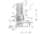
- the upper end bending portion 33 is disposed between the surface sheet metal 22 and the heater pressing portion 40. In the refrigerator-freezer 100, as shown in FIG.
- the heater pressing portion 40 provided at the upper end of the surface frame mold member 24 is behind the upper end bent portion 33 of the heater 23, and the surface sheet metal 22 and the surface frame mold member 24 The movement of the heater 23 is restricted. Therefore, the refrigerator-freezer 100 can prevent the rising of the upper end bent portion 33 of the heater 23 disposed on the partition plate 9. Similarly, in the refrigerator-freezer 100, a lower end bending portion 34 is disposed between the front sheet metal 22 and the heater pressing portion 41. In the refrigerator-freezer 100, as shown in FIG. 4, the heater pressing portion 41 provided at the lower end of the surface frame mold member 24 is behind the lower end bent portion 34 of the heater 23. The movement of the heater 23 is restricted.
- the refrigerator-freezer 100 can prevent the rising of the lower end bent portion 34 of the heater 23 disposed on the partition plate 9.
- the variation in the amount of heat generation due to the variation in the attachment of the heater 23 to the surface metal plate 22 is small, and the partition plate 9 has a stable temperature in all parts from the upper end to the lower end.
- the heater pressing portion 40 and the heater pressing portion 41 are disposed on the back surface of the heater 23, the upper bent portion 33 and the lower bent portion 34 of the heater 23 do not float from the surface sheet metal 22, the surface sheet metal 22 temporally The temperature is also stable.
- the refrigerator-freezer 100 can receive the screw 21 in the receiving portion 40b.
- the screw 21 can be housed in the housing portion 40b, thereby integrating the surface sheet metal 22, the heater 23, the surface frame mold member 24, the heat insulating material 25, and the back member 26 together.
- the movement of the upper end bending portion 33 and the lower end bending portion 34 can be restricted.
- a bottom wall 40b2 is formed in a flat plate shape, and protrudes from the bridge portion 40a to the surface sheet metal 22 side. Therefore, the refrigerator-freezer 100 can face the heater wire 23a in a plane, and the pressure of the heater pressing portion 40 and the heater pressing portion 41 can be prevented from being concentrated on a part of the heater wire 23a.
- the refrigerator-freezer 100 fixes the upper guide member 15 and the lower cover member 27 to the surface metal plate 22 with the screw 21, and the screw 21 is inserted into the screw hole 40 b 3.
- the shaft is disposed in the housing 40 b.
- a bottom wall 40b2 is disposed between the heater 21 and the screw 21 for fixing the front surface metal plate 22 and the front surface frame mold member 24. Therefore, when the heater pressing portion 40 and the heater pressing portion 41 fix the upper guide member 15 and the lower cover member 27 to the surface sheet metal 22 with the screw 21, the heater 23 is prevented from being scratched by the screw 21. it can.
- a chamfered portion 40b4 is formed between the side wall 40b1 and the bottom wall 40b2.
- pressure between the bottom 40b2 and the side wall 40b1 is chamfered, so that the pressure on the heater wire 23a by the corner of the housing 40b accompanying the contact between the housing 40b and the upper bent portion 33 It is possible to avoid concentration.
- the storage portion 40b is a rectangular parallelepiped box-shaped member in which the refrigerating chamber 1 side is opened, but the storage portion 40b is not limited to the configuration, and is closed. It may be formed in a cylindrical shape or a polygonal pillar shape.
- the bridge part 40a is a board material bridged between the two long side parts 24a in the upper end part or lower end part of the surface frame mold member 24, the bridge part 40a is limited to the said structure. For example, it may be a bar.
Landscapes
- Engineering & Computer Science (AREA)
- Chemical & Material Sciences (AREA)
- Combustion & Propulsion (AREA)
- Physics & Mathematics (AREA)
- Mechanical Engineering (AREA)
- Thermal Sciences (AREA)
- General Engineering & Computer Science (AREA)
- Refrigerator Housings (AREA)
Abstract
冷凍冷蔵庫は、貯蔵室を有する冷蔵庫本体と、冷蔵庫本体の前面に設けられ、貯蔵室を開放し閉鎖する複数の扉と、隣り合った複数の扉同士の境界に位置する隙間を閉塞する仕切板と、隣り合った複数の扉に設けられ、仕切板の上下端部と冷蔵庫本体との間に生じる隙間を覆うシール材と、を備え、仕切板は、シール材と対向し、かつ、隣り合った複数の扉の裏面側に対向する表面板金と、表面板金の延設方向に沿って配設され、表面板金を加熱するヒータと、ヒータを収容する表面枠型部材と、を有し、ヒータは、仕切板の上端部と下端部とにおいてヒータ線がそれぞれ曲折する上端曲折部と下端曲折部とを有し、表面枠型部材は、仕切板の上端部と下端部とにおいてヒータ押さえ部をそれぞれ有し、上端曲折部と下端曲折部とは、表面板金とヒータ押さえ部との間に配置されているものである。
Description
本発明は、冷凍冷蔵庫、特に冷凍冷蔵庫の扉に設けられる仕切板の構造に関するものである。
近年、冷凍冷蔵庫の最適な運転を実現させるために、冷凍冷蔵庫が設置される環境に合わせて室温センサ及び湿度センサなどの検知装置が搭載される冷凍冷蔵庫が増えてきている。そして、冷凍冷蔵庫を構成する箱体の熱漏洩量が決まっているため、圧縮機速度あるいは庫内冷却用ファン速度を可変させるインバータ制御装置を搭載して周囲温度に合わせて冷凍能力を調整する冷凍冷蔵庫がある。また、冷蔵室の扉が左右に分割されている冷凍冷蔵庫には、左右の扉の間にヒータを備えた仕切板を設け、周囲の室温及び湿度に合わせて仕切板の表面温度を調節するために、ヒータへの通電を時間割合で変化させて省エネ性を高めるような冷凍冷蔵庫などがある。
このとき、冷蔵室の扉に取り付けられる仕切板内のヒータの発熱量は、その庫外側表面及び仕切板周囲に位置する冷蔵室扉のガスケットなどに露付きが発生しないようにヒータの抵抗値及び配設パターンが設定されている。例えば、加熱手段として発熱量が異なる複数の部位を1本のヒータとしたもので、回転仕切体の長手方向において、両端部より中央部の発熱量を大きくした冷蔵庫が提案されている(特許文献1参照)。また、仕切板内に配設されるヒータの配設パターンを長手方向にジグザグ具合で調整し、ヒータの上部領域での発熱量を上部領域以外の領域よりも小さく設定する冷蔵庫が提案されている(特許文献2参照)。
従来の冷蔵庫では、冷蔵室の扉に設けられた仕切板だけでなく、冷蔵庫の庫外表面に露付きが発生してしまうと、最初は露の大きさが小さくても時間が経過するにつれ次第に露の粒径が大きくなり、表面張力と重力とのバランスにより最終的に露は滴下してしまう。落下した露が床面にまで到達して溜まってしまうと床面を腐らせてしまう場合がある。そのため、どのような環境条件においても冷蔵庫には露付きが発生しないことが望ましい。
仕切板内のヒータの発熱量を大きくしておけば冷蔵庫への露付きの懸念は払拭されるが、冷蔵庫の省エネ性に劣ってしまう場合がある。このようなことから仕切板内のヒータの設計において、露付きが発生しないように、かつ、省エネ性を高めるように仕切板及びヒータの仕様に関して様々な提案がなされている。たとえば、仕切板の発熱密度を変更させた冷蔵庫、あるいは、周囲温度センサ及び湿度センサを搭載し、周囲の温度及び湿度に応じた通電制御を行っている冷蔵庫がある。
また、仕切板は通常、左右の冷蔵室扉のどちらか一方に取り付けられ、その上部と下部とがヒンジで固定され、冷蔵室上部のガイド(突起)により、冷蔵室扉を開閉するときに回動する構造が採用されている。このとき仕切板を回動させるために、冷蔵室の内面壁よりも仕切板の長手方向の長さを短くし、冷蔵室の内面壁と仕切板との間にある程度の隙間を持たせて仕切板が設置される。そして、冷蔵室の内面壁と仕切板との間の隙間を塞ぐために左右の冷蔵室扉のガスケットの上下部分にシールを付け、冷蔵室扉が閉まった状態ではその左右のガスケットのシールが重なり合うようにして隙間を塞いでいる。そのため、上下のシール部分の庫内側は、直接冷蔵室の冷気にさらされ、仕切板の表面よりも比較的温度が低下しやすいために露付き発生の懸念がある。仕切板の上下部分と冷蔵庫本体との隙間を塞ぐガスケットのシールの温度を高くすることが露付きに対して信頼性の高いものとなるため、仕切板内部に設置するヒータの発熱密度とシール部分の温度とを考慮に入れて仕切板を設計しなければならない。ここで、仕切板内に配設されるヒータは、アルミ箔に両面テープで固定されるものもあり、その長手方向の上下端ではヒータ線が曲折していることから反発力が強く、ヒータが仕切板内で貼り付けられていても通電の繰り返しで剥がれて浮き上がる場合がある。ヒータが仕切板から剥がれて浮き上がると、シール部への発熱が弱くなってしまい冷蔵庫の露付きの可能性が高くなってしまう場合がある。
本発明は、上記のような課題を解決するためのものであり、仕切板内のヒータの上端と下端とが浮き上がることのない冷凍冷蔵庫を提供することを目的とする。
本発明に係る冷凍冷蔵庫は、貯蔵室を有する冷蔵庫本体と、冷蔵庫本体の前面に設けられ、貯蔵室を開放し閉鎖する複数の扉と、隣り合った複数の扉同士の境界に位置する隙間を閉塞する仕切板と、隣り合った複数の扉に設けられ、仕切板の上下端部と冷蔵庫本体との間に生じる隙間を覆うシール材と、を備え、仕切板は、シール材と対向し、かつ、隣り合った複数の扉の裏面側に対向する表面板金と、表面板金の延設方向に沿って配設され、表面板金を加熱するヒータと、ヒータを収容する表面枠型部材と、を有し、ヒータは、仕切板の上端部と下端部とにおいてヒータ線がそれぞれ曲折する上端曲折部と下端曲折部とを有し、表面枠型部材は、仕切板の上端部と下端部とにおいてヒータ押さえ部をそれぞれ有し、上端曲折部と下端曲折部とは、表面板金とヒータ押さえ部との間に配置されているものである。
本発明によれば、ヒータを収容する表面枠型部材が、上端部と下端部においてヒータ押さえ部をそれぞれ有し、ヒータ線の上端曲折部と下端曲折部とが、表面板金とヒータ押さえ部材との間に配置されているものである。そのため、冷凍冷蔵庫は、ヒータの背後に配置されたヒータ押さえ部材が、表面板金と表面枠型部材との間のヒータの移動を規制し、仕切板に配設されたヒータの上端と下端とが浮き上がることを抑止することができる。
以下、本発明の実施の形態に係る冷凍冷蔵庫100について図面等を参照しながら説明する。なお、図1を含む以下の図面では、各構成部材の相対的な寸法の関係及び形状等が実際のものとは異なる場合がある。また、以下の図面において、同一の符号を付したものは、同一又はこれに相当するものであり、このことは明細書の全文において共通することとする。また、理解を容易にするために方向を表す用語(例えば「上」、「下」、「右」、「左」、「前」、「後」など)を適宜用いるが、それらの表記は、説明の便宜上、そのように記載しているだけであって、装置あるいは部品の配置及び向きを限定するものではない。
実施の形態1.
(冷凍冷蔵庫100)
図1は、本発明の実施の形態1に係る冷凍冷蔵庫100の正面図である。図1に示すX軸は、冷凍冷蔵庫100の幅方向を示し、Z軸は冷凍冷蔵庫100の上下方向を示すものである。より詳細には、X軸においてX1側を左側、X2側を右側、Z軸においてZ1側を上側、Z2側を下側として冷凍冷蔵庫100を説明する。また、明細書中における各構成部材同士の位置関係(例えば、上下関係等)は、原則として、冷凍冷蔵庫100を使用可能な状態に設置したときのものである。
(冷凍冷蔵庫100)
図1は、本発明の実施の形態1に係る冷凍冷蔵庫100の正面図である。図1に示すX軸は、冷凍冷蔵庫100の幅方向を示し、Z軸は冷凍冷蔵庫100の上下方向を示すものである。より詳細には、X軸においてX1側を左側、X2側を右側、Z軸においてZ1側を上側、Z2側を下側として冷凍冷蔵庫100を説明する。また、明細書中における各構成部材同士の位置関係(例えば、上下関係等)は、原則として、冷凍冷蔵庫100を使用可能な状態に設置したときのものである。
図1に示す冷凍冷蔵庫100は、間冷式の冷蔵庫であり、鋼板製の外箱と、及び、前面側に開口部を形成する樹脂製の内箱とから構成される冷蔵庫本体50を備える。冷蔵庫本体50は、外箱と内箱との間に断熱材が発泡充填されている。また、冷蔵庫本体50の内部の収容空間は、複数の貯蔵室を有する。冷蔵庫本体50は、図1に記載のように複数の貯蔵室に区分けされており、冷蔵室1、製氷室2、小型冷凍室3、冷凍室4および野菜室5の5種の貯蔵室が形成されている。冷凍冷蔵庫100は、冷蔵室1、製氷室2、小型冷凍室3、冷凍室4および野菜室5が、それぞれ仕切部材によって区画されており、断熱されている。冷凍冷蔵庫100は、冷蔵庫本体50の上部から冷蔵室1、製氷室2及び小型冷凍室3、冷凍室4、野菜室5の順番に配置されている。しかし、冷凍冷蔵庫100は、冷蔵室1に、冷蔵室左扉7と、冷蔵室右扉8とが左右に分割されて配置され、その間に仕切板9がある構成であれば、貯蔵室の配置は任意である。例えば、冷凍冷蔵庫100は、冷凍室4の位置に野菜室5が配置されてもよく、野菜室5の位置に冷凍室4が設けられてもよい。また、冷凍冷蔵庫100は、冷蔵室左扉7の上側ヒンジ部に周囲温度センサ及び周囲湿度センサ(図示せず)を搭載しているが、温度及び湿度などの周囲環境が検出できるのであれば周囲温度センサ及び周囲湿度センサの設置場所は問わない。
各貯蔵室の内部は、収納する食品及び用途によって異なる温度帯に設定されている。冷蔵室1は、冷蔵温度帯(例えば、約3~5℃)に設定され、食品などの被冷却物を収納する貯蔵室である。製氷室2は、室内に製氷機が設けられ、その製氷機によって製造された氷を保存する貯蔵室である。小型冷凍室3は、例えば、用途に応じて温度帯を切り換えることができる貯蔵室である。冷凍室4は、0℃未満の冷凍温度帯(例えば、-18℃以下)に設定され、貯蔵品を冷凍し収納する貯蔵室である。野菜室5は、冷蔵室1よりも設定温度が高い冷蔵温度帯(例えば、約3~7℃)に設定され、特に野菜を冷蔵するのに適している貯蔵室である。
冷凍冷蔵庫100は、冷蔵庫本体50の前面に設けられ、冷蔵庫本体50の貯蔵室を開放し又は閉鎖する複数の箱状の扉を有している。具体的には、冷蔵室1、製氷室2、小型冷凍室3、冷凍室4および野菜室5の各貯蔵室において、それぞれ冷蔵室左扉7及び冷蔵室右扉8、製氷室扉10、小型冷凍室扉11、冷凍室扉12並びに野菜室扉13が、各貯蔵室の開口部を開閉するように設けられている。これらの扉を開閉することで冷蔵室1、製氷室2、小型冷凍室3、冷凍室4および野菜室5の各貯蔵室は外部空間に開放され又は外部空間と遮断される。冷蔵室左扉7および冷蔵室右扉8は、観音開き式の回転式扉であり、製氷室扉10、小型冷凍室扉11、冷凍室扉12および野菜室扉13は引出し式の扉である。
(冷蔵室左扉7及び冷蔵室右扉8)
冷蔵室左扉7および冷蔵室右扉8について更に詳細に説明する。冷蔵庫本体50には、冷蔵室左扉7を開閉自在に軸支するヒンジ14が設けられており、このヒンジ14によって、冷蔵庫本体50と冷蔵室左扉7とが接続されている。同様に、冷蔵庫本体50には、冷蔵室右扉8を開閉自在に軸支するヒンジ14が設けられており、このヒンジ14によって、冷蔵庫本体50と冷蔵室右扉8とが接続されている。使用者は、冷蔵室左扉7及び冷蔵室右扉8の下部に設けられたハンドル(図示せず)を引く、又は押すことにより、冷蔵室左扉7及び冷蔵室右扉8を開閉することができる。
冷蔵室左扉7および冷蔵室右扉8について更に詳細に説明する。冷蔵庫本体50には、冷蔵室左扉7を開閉自在に軸支するヒンジ14が設けられており、このヒンジ14によって、冷蔵庫本体50と冷蔵室左扉7とが接続されている。同様に、冷蔵庫本体50には、冷蔵室右扉8を開閉自在に軸支するヒンジ14が設けられており、このヒンジ14によって、冷蔵庫本体50と冷蔵室右扉8とが接続されている。使用者は、冷蔵室左扉7及び冷蔵室右扉8の下部に設けられたハンドル(図示せず)を引く、又は押すことにより、冷蔵室左扉7及び冷蔵室右扉8を開閉することができる。
図2は、図1の冷凍冷蔵庫100のA部を示す拡大斜視図である。図3は、図1の冷凍冷蔵庫100のB-B線断面図である。図2は、冷凍冷蔵庫100の冷蔵室左扉7を閉じ、冷蔵室右扉8を開けたときの冷蔵室1の上部を表したものである。図2に示すY軸は、冷凍冷蔵庫100の奥行方向を示すものである。より詳細には、Y軸においてY1側を前側、Y2側を後側又は奥側として冷凍冷蔵庫100を説明する。図3は、冷蔵室左扉7を閉じたときの仕切板9の上部の断面を示している(冷蔵室扉は図示せず)。冷蔵室左扉7及び冷蔵室右扉8の冷蔵室1側の壁部には、マグネットを内封したガスケット16が取り付けられている。冷蔵室左扉7及び冷蔵室右扉8が閉じられている際には、表面板金22と冷蔵室左扉7及び冷蔵室右扉8との間には、夫々ガスケット16が配置されている。ガスケット16は、冷蔵室左扉7及び冷蔵室右扉8を閉めているときには、冷蔵庫本体50の前側フランジ部50aの板金部及び仕切板9の表面板金22と密着する。これらのガスケット16は、冷蔵室1から冷凍冷蔵庫100の外部に、冷気が漏れることを抑制するものである。
(左上シール材17及び右上シール材18)
冷蔵室左扉7のガスケット16は、冷蔵室右扉8と対向する側面の上端部において冷蔵室右扉8側に突出する平板状の左上シール材17を有している。左上シール材17は、冷蔵室左扉7を閉じているときには、後述する仕切板9の前側に位置し、冷蔵室1側の面が仕切板9及び前側フランジ部50aと当接し、庫外側の面が後述する右上シール材18と当接する。なお、この際に左上シール材17が当接する前側フランジ部50aは、冷蔵室1の上部を構成する部分である。あるいは、冷蔵室左扉7を閉じているときには、左上シール材17は、後述する仕切板9の前側に位置し、冷蔵室1側の面が、後述する右上シール材18と当接する。
冷蔵室左扉7のガスケット16は、冷蔵室右扉8と対向する側面の上端部において冷蔵室右扉8側に突出する平板状の左上シール材17を有している。左上シール材17は、冷蔵室左扉7を閉じているときには、後述する仕切板9の前側に位置し、冷蔵室1側の面が仕切板9及び前側フランジ部50aと当接し、庫外側の面が後述する右上シール材18と当接する。なお、この際に左上シール材17が当接する前側フランジ部50aは、冷蔵室1の上部を構成する部分である。あるいは、冷蔵室左扉7を閉じているときには、左上シール材17は、後述する仕切板9の前側に位置し、冷蔵室1側の面が、後述する右上シール材18と当接する。
冷蔵室右扉8のガスケット16は、冷蔵室左扉7と対向する側面の上端部において冷蔵室左扉7側に突出する平板状の右上シール材18を有している。なお、図2には、冷蔵室右扉8を閉じているときの右上シール材18が一点鎖線で示されている。冷蔵室右扉8を閉じているときには、右上シール材18は、後述する仕切板9の前側に位置し、冷蔵室1側の面が、左上シール材17と当接する。あるいは、右上シール材18は、冷蔵室右扉8を閉じているときには、後述する仕切板9の前側に位置し、冷蔵室1側の面が仕切板9及び前側フランジ部50aと当接し、庫外側の面が左上シール材17と当接する。なお、この際に右上シール材18が当接する前側フランジ部50aは、冷蔵室1の上部を構成する部分である。
左上シール材17及び右上シール材18は、冷蔵室左扉7及び冷蔵室右扉8が閉じられているときには互いに重なり合うように配置されて後述するガイドパーツ51と仕切板9との間にできる隙間Gを塞ぐ。左上シール材17及び右上シール材18は、隣り合った冷蔵室左扉7及び冷蔵室右扉8に設けられ、仕切板9の上端部と冷蔵庫本体50との間に生じる隙間Gを覆い、冷蔵室1の冷気を庫外と遮断している。
(左下シール材19及び右下シール材20)
図4は、図1の冷凍冷蔵庫100のC-C線断面図である。図4は、冷蔵室左扉7を閉じたときの仕切板9の下部の断面を示している。仕切板9の上端側と同様に、冷蔵室左扉7のガスケット16は、冷蔵室右扉8と対向する側面の下端部において冷蔵室右扉8側に突出する平板状の左下シール材19を有している。左下シール材19は、冷蔵室左扉7を閉じているときには、仕切板9の前側に位置し、冷蔵室1側の面が仕切板9及び前側フランジ部50aと当接し、庫外側の面が後述する右下シール材20と当接する。なお、この際に左下シール材19が当接する前側フランジ部50aは、冷蔵室1の下部を構成する部分である。あるいは、冷蔵室左扉7を閉じているときには、左下シール材19は、仕切板9の前側に位置し、冷蔵室1側の面が、後述する右下シール材20と当接する。
図4は、図1の冷凍冷蔵庫100のC-C線断面図である。図4は、冷蔵室左扉7を閉じたときの仕切板9の下部の断面を示している。仕切板9の上端側と同様に、冷蔵室左扉7のガスケット16は、冷蔵室右扉8と対向する側面の下端部において冷蔵室右扉8側に突出する平板状の左下シール材19を有している。左下シール材19は、冷蔵室左扉7を閉じているときには、仕切板9の前側に位置し、冷蔵室1側の面が仕切板9及び前側フランジ部50aと当接し、庫外側の面が後述する右下シール材20と当接する。なお、この際に左下シール材19が当接する前側フランジ部50aは、冷蔵室1の下部を構成する部分である。あるいは、冷蔵室左扉7を閉じているときには、左下シール材19は、仕切板9の前側に位置し、冷蔵室1側の面が、後述する右下シール材20と当接する。
冷蔵室右扉8のガスケット16は、冷蔵室左扉7と対向する側面の下端部において冷蔵室左扉7側に突出する平板状の右下シール材20を有している。冷蔵室右扉8を閉じているときには、右下シール材20は、仕切板9の前側に位置し、冷蔵室1側の面が、左下シール材19と当接する。あるいは、右下シール材20は、冷蔵室右扉8を閉じているときには、仕切板9の前側に位置し、冷蔵室1側の面が仕切板9及び前側フランジ部50aと当接し、庫外側の面が左下シール材19と当接する。なお、この際に右下シール材20が当接する前側フランジ部50aは、冷蔵室1の下部を構成する部分である。
左下シール材19及び右下シール材20は、冷蔵室左扉7及び冷蔵室右扉8が閉じられているときには互いに重なり合うように配置されて、仕切板9と冷蔵室1の床面1aとの間にできる隙間Hを塞ぐ。仕切板9の下部には、仕切板9の回動を誘導する突起などはないが、仕切板9のスムーズな回動をさせるため、仕切板9と冷蔵室1の床面1aとの間に隙間Hが形成されている。左下シール材19及び右下シール材20は、隣り合った冷蔵室左扉7及び冷蔵室右扉8に設けられ、仕切板9の下端部と冷蔵庫本体50との間に生じる隙間Hを覆い、冷蔵室1の冷気を庫外と遮断している。
(仕切板9)
冷凍冷蔵庫100は、冷蔵室左扉7と冷蔵室右扉8との間に仕切板9を有する。図1~図4を用いて仕切板9について説明する。仕切板9は、図1に示すように、隣り合った扉同士の境界に位置する隙間を閉塞する。仕切板9は、冷蔵室左扉7と冷蔵室右扉8との間の隙間を埋め、冷蔵室1からの冷気漏れ、及び、結露を抑えるものである。仕切板9は、長尺状であって、冷蔵室左扉7を構成する内板の長手方向(Z軸方向)に沿って配置され、内板の上下部分に回動自在にヒンジ固定(図示せず)されている。仕切板9の長手方向(Z方向)の全長は、図3及び図4に示すように、その上部に設置されるガイドパーツ51から冷蔵室1の床面1aまでの距離よりも小さい。仕切板9は、冷蔵庫本体50のガイドパーツ51と仕切板9の上端部との間に隙間Gを形成し、及び、冷蔵室1の床面1aと仕切板9の下端部との間に隙間Hを形成して冷蔵室左扉7に取り付けられている。仕切板9の上下に設けられた隙間G及び隙間Hは、仕切板9がスムーズに回動出来る程度に、それぞれ2~5mmの間隔で設定されている。なお、仕切板9は、図2に示すように冷蔵室左扉7に仕取り付けられているが、仕切板9は、冷蔵室左扉7ではなく冷蔵室右扉8に取り付けられてもよい。
冷凍冷蔵庫100は、冷蔵室左扉7と冷蔵室右扉8との間に仕切板9を有する。図1~図4を用いて仕切板9について説明する。仕切板9は、図1に示すように、隣り合った扉同士の境界に位置する隙間を閉塞する。仕切板9は、冷蔵室左扉7と冷蔵室右扉8との間の隙間を埋め、冷蔵室1からの冷気漏れ、及び、結露を抑えるものである。仕切板9は、長尺状であって、冷蔵室左扉7を構成する内板の長手方向(Z軸方向)に沿って配置され、内板の上下部分に回動自在にヒンジ固定(図示せず)されている。仕切板9の長手方向(Z方向)の全長は、図3及び図4に示すように、その上部に設置されるガイドパーツ51から冷蔵室1の床面1aまでの距離よりも小さい。仕切板9は、冷蔵庫本体50のガイドパーツ51と仕切板9の上端部との間に隙間Gを形成し、及び、冷蔵室1の床面1aと仕切板9の下端部との間に隙間Hを形成して冷蔵室左扉7に取り付けられている。仕切板9の上下に設けられた隙間G及び隙間Hは、仕切板9がスムーズに回動出来る程度に、それぞれ2~5mmの間隔で設定されている。なお、仕切板9は、図2に示すように冷蔵室左扉7に仕取り付けられているが、仕切板9は、冷蔵室左扉7ではなく冷蔵室右扉8に取り付けられてもよい。
仕切板9は、図2及び図3に示すように、冷蔵室左扉7を閉じると、冷蔵庫本体50の前側フランジ部50aに固定されているガイドパーツ51の突起部52が、仕切板9の上端に取り付けられた上側ガイド部材15に形成された溝部15aに挿入される。突起部52は、冷蔵庫本体50のガイドパーツ51から下方に突出するように設けられている。
図5は、本発明の実施の形態1に係る冷凍冷蔵庫100に用いる仕切板9の分解図である。なお、図5において、X軸で表す仕切板9の幅方向、Y軸で表す仕切板9の奥行方向、Z軸で表す仕切板9の高さ方向は、冷蔵室左扉7及び冷蔵室右扉8が閉じられた際の、仕切板9の配置に基づくものである。図2~図5を用いて仕切板9の構造を更に説明する。仕切板9は、表面板金22と、ヒータ23と、表面枠型部材24と、断熱材25と、背面部材26と、を有する。そして、冷凍冷蔵庫100は、これらが冷凍冷蔵庫100の筐体外側から庫内側に向かってこの順序に積層されて配置される。仕切板9は、内側にヒータ23が貼り付けられた表面板金22が、表面枠型部材24に形成されたツメと嵌合させられ、表面枠型部材24と背面部材26との間に断熱材25を配置して、背面部材26にツメ嵌合させ合体させられる。また、仕切板9は、上側ガイド部材15と、下側カバー部材27と、上側ヒンジ部材28と、下側ヒンジ部材29とを有する。背面部材26には、上側ヒンジ部材28と、下側ヒンジ部材29と、上側ガイド部材15と、下側カバー部材27とが取り付けられる。仕切板9は、一方の端部において、上側ガイド部材15及び上側ヒンジ部材28が取り付けられており、他方の端部において、下側カバー部材27及び下側ヒンジ部材29が取り付けられている。仕切板9は、上側ヒンジ部材28また下側ヒンジ部材29がネジによって冷蔵室左扉7の内板に固定される。なお、仕切板9は、積層方向(Y軸方向)において、表面板金22が、冷蔵室1からもっとも遠く、また、背面部材26が、冷蔵室1からもっとも近くなるように、冷蔵室左扉7又は冷蔵室右扉8に取り付けられる。
仕切板9は、仕切板9が設けられた冷蔵室左扉7が開く際には、下側ヒンジ部材29に取り付けられたバネ32によって冷蔵室左扉7の内板に沿うように仕切板9が回動し、背面部材26と冷蔵室左扉7の内板とが対向する。あるいは、仕切板9が設けられた冷蔵室右扉8が開く際には、下側ヒンジ部材29に取り付けられたバネ32によって冷蔵室右扉8の内板に沿うように仕切板9が回動し、背面部材26と冷蔵室右扉8の内板とが対向する。
仕切板9は、仕切板9が設けられた冷蔵室左扉7が閉じる際には、上側ガイド部材15が、溝部15aに挿入されたガイドパーツ51の突起部52によって案内されるので、冷蔵室左扉7の内板とのヒンジ固定を中心として回動する。あるいは、仕切板9は、仕切板9が設けられた冷蔵室右扉8が閉じる際には、上側ガイド部材15が、溝部15aに挿入されたガイドパーツ51の突起部52によって案内されるので、冷蔵室右扉8の内板とのヒンジ固定を中心として回動する。仕切板9は、冷蔵室左扉7及び冷蔵室右扉8が閉じている際には、冷蔵室左扉7及び冷蔵室右扉8と、冷蔵庫本体50との間に配置され、冷蔵室左扉7及び冷蔵室右扉8の間の隙間を塞ぐ。この際、仕切板9は、表面板金22が、筐体外側に面しており、ガスケット16と当接し、背面部材26が冷蔵室1の庫内側に面している。
(表面板金22)
表面板金22は、例えば一方向(Z軸方向)に延びる板状の金属であり、幅方向(X軸方向)の中心が、冷蔵室左扉7及び冷蔵室右扉8同士の境界に設けられた隙間の中心と一致している。冷蔵室左扉7及び冷蔵室右扉8が閉じられている際には、表面板金22は、左上シール材17又は右上シール材18と対向し、かつ、隣り合った冷蔵室左扉7及び冷蔵室右扉8の裏面側に対向する。さらに、冷蔵室左扉7及び冷蔵室右扉8が閉じられている際には、表面板金22は、左下シール材19又は右下シール材20と対向し、かつ、隣り合った冷蔵室左扉7及び冷蔵室右扉8の裏面側に対向する。表面板金22は、ヒータ23による熱を、冷蔵室左扉7、冷蔵室右扉8、ガスケット16、左上シール材17、右上シール材18、左下シール材19及び右下シール材20に伝達するものである。表面板金22が、ヒータ23の発する熱を伝導することにより、仕切板9、冷蔵室左扉7、冷蔵室右扉8、ガスケット16、左上シール材17、右上シール材18、左下シール材19及び右下シール材20の露付きが抑制される。また、表面板金22は、後述するヒータ23におけるアルミニウム箔23bの強度を向上させる機能も備えている。更に、前述の如く、表面板金22は、冷蔵室左扉7及び冷蔵室右扉8が閉じられている際に、ガスケット16に密着している。これにより、冷凍冷蔵庫100の内部から冷凍冷蔵庫100の外部に、冷気が漏れることが抑制される。また、前述の如く、仕切板9は、積層方向(Y軸方向)において、表面板金22が、冷蔵室1からもっとも遠くなるように、冷蔵室左扉7又は冷蔵室右扉8に取り付けられる。このように、表面板金22が冷蔵室1から離間することによって、表面板金22に伝わったヒータ23の熱が、冷蔵室1に伝わり難くなり、冷蔵室1の庫内温度の上昇が抑制される。
表面板金22は、例えば一方向(Z軸方向)に延びる板状の金属であり、幅方向(X軸方向)の中心が、冷蔵室左扉7及び冷蔵室右扉8同士の境界に設けられた隙間の中心と一致している。冷蔵室左扉7及び冷蔵室右扉8が閉じられている際には、表面板金22は、左上シール材17又は右上シール材18と対向し、かつ、隣り合った冷蔵室左扉7及び冷蔵室右扉8の裏面側に対向する。さらに、冷蔵室左扉7及び冷蔵室右扉8が閉じられている際には、表面板金22は、左下シール材19又は右下シール材20と対向し、かつ、隣り合った冷蔵室左扉7及び冷蔵室右扉8の裏面側に対向する。表面板金22は、ヒータ23による熱を、冷蔵室左扉7、冷蔵室右扉8、ガスケット16、左上シール材17、右上シール材18、左下シール材19及び右下シール材20に伝達するものである。表面板金22が、ヒータ23の発する熱を伝導することにより、仕切板9、冷蔵室左扉7、冷蔵室右扉8、ガスケット16、左上シール材17、右上シール材18、左下シール材19及び右下シール材20の露付きが抑制される。また、表面板金22は、後述するヒータ23におけるアルミニウム箔23bの強度を向上させる機能も備えている。更に、前述の如く、表面板金22は、冷蔵室左扉7及び冷蔵室右扉8が閉じられている際に、ガスケット16に密着している。これにより、冷凍冷蔵庫100の内部から冷凍冷蔵庫100の外部に、冷気が漏れることが抑制される。また、前述の如く、仕切板9は、積層方向(Y軸方向)において、表面板金22が、冷蔵室1からもっとも遠くなるように、冷蔵室左扉7又は冷蔵室右扉8に取り付けられる。このように、表面板金22が冷蔵室1から離間することによって、表面板金22に伝わったヒータ23の熱が、冷蔵室1に伝わり難くなり、冷蔵室1の庫内温度の上昇が抑制される。
表面板金22は、矩形板状の基部22aと、基部22aの長手方向の両端部に設けられた固定部22bと、基部22aの短手方向(X軸方向)における両側部に設けられたフランジ部22cと、を有する。また、表面板金22は、基部22aの短手方向(X軸方向)における一方の側(X1)のフランジ部22cに設けられた複数の係合部22dと、他方の側(X2)のフランジ部22cに設けられた複数の切起こし部22eとを備えている。
固定部22bは、基部22aの長手方向(Z軸方向)における両端部から、冷蔵室1に向けて徐々に幅が狭くなりつつ延びる逆台形状をなしている。この固定部22bの中央には、固定孔22b1が形成されている。図5に示すように、上側ガイド部材15及び下側カバー部材27に挿通されたネジ21が、この固定孔22b1に挿通されてねじ止めされることで、背面部材26と共に表面板金22が、上側ガイド部材15及び下側カバー部材27と結合される。フランジ部22cは、基部22aの両側部から冷蔵室1に向かう方向(Y軸方向)に延びるものである。
係合部22dは、基部22aの幅方向(X軸方向)における一方の側(X1)のフランジ部22cの端部から冷蔵室1に向かう方向に対し垂直の方向のうち、基部22aの幅方向(X軸方向)に延びるものである。すなわち、係合部22dは、冷凍冷蔵庫100の冷蔵室左扉7が閉じた状態においては、冷凍冷蔵庫100の左側方を向いている。係合部22dは、表面板金22と表面枠型部材24とを係合する際に使用されるものである。なお、図5において、係合部22dは、基部22aの幅方向(X軸方向)における一方の側(X1)のフランジ部22cに3個設けられているが、2個以下でもよいし、4個以上でもよい。また、フランジ部22cの端部における全体から延びる1個の係合部22dとしてもよい。このように、表面板金22は、仕切板9の幅方向(X軸方向)における少なくとも一方の側において係合部22dを有している。
切起こし部22eは、基部22aの幅方向(X軸方向)における他方の側(X2)のフランジ部22cの端部から冷蔵室1に向かう方向(Y軸方向)に切り起こされたものである。切起こし部22eは、係合部22dと共に、表面板金22と表面枠型部材24とを係合する際に使用されるものである。この切起こし部22eには、切起こし孔22e1が形成されており、切起こし孔22e1を利用して、表面板金22と表面枠型部材24とが係合される。なお、図5において、切起こし部22eは、基部22aの幅方向(X軸方向)における他方の側(X2)のフランジ部22cに4個設けられているが、3個以下でもよいし、5個以上でもよい。また、フランジ部22cの端部における全体から延びる1個の切起こし部22eとしてもよい。係合部22dと切起こし部22eとは、基部22aの幅方向(X軸方向)において交互に配置されている。これにより、表面板金22と表面枠型部材24とが係合される際、係合する部分における力が分散される。なお、係合部22dと切起こし部22eとは、基部22aの幅方向(X軸方向)において同じ位置に配置されてもよいし、また、それらの位置は適宜変更することができる。また、係合部22dと切起こし部22eとの数は、異なっていてもよい。なお、表面板金22において、切起こし部22eの代わりに、係合部22dが設けられてもよい。即ち、表面板金22は、仕切板9の幅方向(X軸方向)における両方の側において係合部22dを有するように構成してもよい。
(ヒータ23)
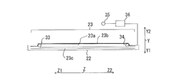
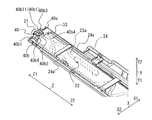
図6は、図5のヒータ23の構造を示す模式図である。図7は、本発明の実施の形態1に係る冷凍冷蔵庫100に用いる仕切板9の内部構造を示す上部斜視図である。ヒータ23は、表面板金22の延設方向に沿って配設され、表面板金22を加熱する。ヒータ23は、仕切板9の表面板金22の冷蔵室1側に貼り付けられている。ヒータ23は、図6に示すように、ニクロム線等のヒータ線23aが、一方向(Z軸方向)に延在した厚さ50μm程度のアルミニウム箔23bの全体に渡って載置されたものである。アルミニウム箔23b及びヒータ線23aは、両面テープ23cによって、表面板金22に貼り付けられる。このヒータ23による熱が、表面板金22によって、冷蔵室左扉7、冷蔵室右扉8、ガスケット16、左上シール材17、右上シール材18、左下シール材19及び右下シール材20に伝達される。ヒータ23は、検出部35によって検出された周囲温度、湿度等に基づき、制御部36によって通電時間が制御され、例えば10秒のうち5秒通電などの制御が行われて発熱する。
図6は、図5のヒータ23の構造を示す模式図である。図7は、本発明の実施の形態1に係る冷凍冷蔵庫100に用いる仕切板9の内部構造を示す上部斜視図である。ヒータ23は、表面板金22の延設方向に沿って配設され、表面板金22を加熱する。ヒータ23は、仕切板9の表面板金22の冷蔵室1側に貼り付けられている。ヒータ23は、図6に示すように、ニクロム線等のヒータ線23aが、一方向(Z軸方向)に延在した厚さ50μm程度のアルミニウム箔23bの全体に渡って載置されたものである。アルミニウム箔23b及びヒータ線23aは、両面テープ23cによって、表面板金22に貼り付けられる。このヒータ23による熱が、表面板金22によって、冷蔵室左扉7、冷蔵室右扉8、ガスケット16、左上シール材17、右上シール材18、左下シール材19及び右下シール材20に伝達される。ヒータ23は、検出部35によって検出された周囲温度、湿度等に基づき、制御部36によって通電時間が制御され、例えば10秒のうち5秒通電などの制御が行われて発熱する。
ヒータ線23aは、一本の線状構造であり、ヒータ23の長手方向の中央では、蛇行した状態で配置されている。また、ヒータ線23aは、ヒータ23の長手方向の両端部において、ヒータ線23aの端部が、ヒータ23の反対側の端部の方向に向かうように180°曲折されている。ヒータ23は、仕切板9の上端部と下端部とにおいてヒータ線23aがそれぞれ曲折する上端曲折部33と下端曲折部34とを有する。上端曲折部33は、表面板金22とヒータ押さえ部40との間に配置されている。また、下端曲折部34は、表面板金22とヒータ押さえ部41との間に配置されている。ヒータ23の上端部に位置するヒータ線23aの上端曲折部33と、ヒータ23の下端部に位置するヒータ線23aの下端曲折部34とは、ヒータ線23aの曲折による反発力がヒータ線23aの他の箇所より強い。また、ヒータ23の上端部に位置する上端曲折部33と、ヒータ23の下端部に位置する下端曲折部34とは、ヒータ23への通電及び非通電によるヒートサイクルにより表面板金22に対する接着力の低下が生じやすい。そのため、ヒータ23の上端部に位置する上端曲折部33と、ヒータ23の下端部に位置する下端曲折部34とは、ヒータ線23aの他の箇所よりも表面板金22から剥がれやすい傾向にある。
(表面枠型部材24)
表面枠型部材24は、図5に示すように、長尺状に形成された矩形の枠体である。表面枠型部材24は、長手方向の壁部を構成する2つの長辺部24aと、2つの長辺部24aの間に架け渡され、短手方向の壁部を構成する複数の短辺部24bを有する。表面枠型部材24は、各短辺部24bの間と、2つの長辺部24aの間とで囲まれた部分は、貫通した開口が形成されている。表面枠型部材24は、例えば、樹脂から形成されている。表面枠型部材24と表面板金22との間には、ヒータ23が配置され、表面枠型部材24は、ヒータ線23aを、枠体内に収容する。この表面枠型部材24は、表面板金22よりも冷蔵室1側に配置されている。表面枠型部材24の上端部には、ヒータ押さえ部40が設けられ、表面枠型部材24の下端部には、ヒータ押さえ部41が設けられている。
表面枠型部材24は、図5に示すように、長尺状に形成された矩形の枠体である。表面枠型部材24は、長手方向の壁部を構成する2つの長辺部24aと、2つの長辺部24aの間に架け渡され、短手方向の壁部を構成する複数の短辺部24bを有する。表面枠型部材24は、各短辺部24bの間と、2つの長辺部24aの間とで囲まれた部分は、貫通した開口が形成されている。表面枠型部材24は、例えば、樹脂から形成されている。表面枠型部材24と表面板金22との間には、ヒータ23が配置され、表面枠型部材24は、ヒータ線23aを、枠体内に収容する。この表面枠型部材24は、表面板金22よりも冷蔵室1側に配置されている。表面枠型部材24の上端部には、ヒータ押さえ部40が設けられ、表面枠型部材24の下端部には、ヒータ押さえ部41が設けられている。
(ヒータ押さえ部40及びヒータ押さえ部41)
図7に示す仕切板9は、後述する断熱材25を組み込む前までの組立途中の仕切板9である。なお、図7において、X軸で表す仕切板9の幅方向、Y軸で表す仕切板9の奥行方向、Z軸で表す仕切板9の高さ方向は、冷蔵室左扉7及び冷蔵室右扉8が閉じられた際の、仕切板9の配置に基づくものである。図3、図4、図5及び図7を用いて、仕切板9に使用されるヒータ押さえ部40及びヒータ押さえ部41を説明する。なお、ヒータ23の下端曲折部34の構造はヒータ23の上端曲折部33と同じ構造である。また、仕切板9の下端部に使用されるヒータ押さえ部41の構造は、ヒータ23の上端部に使用されるヒータ押さえ部40の構造と同じ構造である。そのため、図7では、仕切板9の上端部の構造のみ示しているが、特に説明のない場合には、仕切板9の上端部のヒータ押さえ部40及び上端曲折部33の説明は、仕切板9の下端部のヒータ押さえ部41及び下端曲折部34にも適用される。
図7に示す仕切板9は、後述する断熱材25を組み込む前までの組立途中の仕切板9である。なお、図7において、X軸で表す仕切板9の幅方向、Y軸で表す仕切板9の奥行方向、Z軸で表す仕切板9の高さ方向は、冷蔵室左扉7及び冷蔵室右扉8が閉じられた際の、仕切板9の配置に基づくものである。図3、図4、図5及び図7を用いて、仕切板9に使用されるヒータ押さえ部40及びヒータ押さえ部41を説明する。なお、ヒータ23の下端曲折部34の構造はヒータ23の上端曲折部33と同じ構造である。また、仕切板9の下端部に使用されるヒータ押さえ部41の構造は、ヒータ23の上端部に使用されるヒータ押さえ部40の構造と同じ構造である。そのため、図7では、仕切板9の上端部の構造のみ示しているが、特に説明のない場合には、仕切板9の上端部のヒータ押さえ部40及び上端曲折部33の説明は、仕切板9の下端部のヒータ押さえ部41及び下端曲折部34にも適用される。
ヒータ押さえ部40は、橋架部40aと、収容部40bとを有する。橋架部40aは、表面枠型部材24の上端部又は下端部において、2つの長辺部24aの間に架け渡された板材である。橋架部40aは、2つの長辺部24aと一体に形成されている。
収容部40bは、表面枠型部材24の短手方向において橋架部40aの中央に形成されており、冷蔵室1側が開口している直方体状に形成された箱状部材である。収容部40bは、側壁40b1と、底壁40b2とを有する。収容部40bの側壁40b1は、橋架部40aと一体に形成されている。収容部40bの側壁40b1は、筒状に構成されており、冷蔵室1側の一端は開口しており、表面板金22側の他端には底壁40b2が形成されている。側壁40b1は、冷蔵室1側からの平面視で、略矩形状に構成されている。側壁40b1のうち、表面枠型部材24の長手方向の端面を構成する端壁部40b11には、ネジ穴40b3が形成されている。表面枠型部材24の上端部に形成されたネジ穴40b3にネジ21が挿入され、表面枠型部材24が上側ガイド部材15と共締めされることで、表面枠型部材24と背面部材26とが断熱材25を収容して固定される。また、表面枠型部材24の上端部に形成されたネジ穴40b3にネジ21が挿入され、表面枠型部材24が上側ガイド部材15と共締めされることで、表面枠型部材24と表面板金22とがヒータ23を収容して固定される。同様に、表面枠型部材24の下端部に形成されたネジ穴40b3にネジ21が挿入され、表面枠型部材24が下側カバー部材27と共締めされることで、表面枠型部材24と背面部材26とが断熱材25を収容して固定される。また、表面枠型部材24の下端部に形成されたネジ穴40b3にネジ21が挿入され、表面枠型部材24が下側カバー部材27と共締めされることで、表面枠型部材24と表面板金22とがヒータ23を収容して固定される。上側ガイド部材15をネジ21で表面板金22に固定する際に、ネジ穴40b3に挿入されたネジ21の軸は、収容部40b内に配置されている。同様に、下側カバー部材27をネジ21で表面板金22に固定する際に、ネジ穴40b3に挿入されたネジ21の軸は、収容部40b内に配置されている。すなわち、上側ガイド部材15及び下側カバー部材27をネジ21で表面板金22に固定する際に、表面板金22と表面枠型部材24とを固定するネジ21の軸と、ヒータ23との間には、収容部40bの底壁40b2が配置されている。
収容部40bの底壁40b2は、平板状に形成されており、橋架部40aから表面板金22側に突出している。仕切板9において、底壁40b2と、表面板金22との間の距離は、橋架部40aと、表面板金22との間の距離よりも狭い。表面枠型部材24と、表面板金22との間にヒータ23が配置されると、ヒータ押さえ部40において、底壁40b2と表面板金22との間には、ヒータ23の上端曲折部33が配置される。底壁40b2と、表面板金22との間にヒータ23が配置された場合には、底壁40b2と表面板金22との間の距離は、ヒータ23の上端曲折部33の厚さと略同じであることが望ましい。上端曲折部33の表面板金22からの浮き上がりを防止するためである。収容部40bは、底壁40b2と側壁40b1との間に面取部40b4が形成されている。底壁40b2と、側壁40b1との間が面取りされていることで、収容部40bと上端曲折部33との接触に伴う収容部40bの角部によるヒータ線23aへの圧力が集中することを避けることができる。
同様に、表面枠型部材24と、表面板金22との間にヒータ23が配置されると、ヒータ押さえ部41において、底壁40b2と表面板金22との間には、ヒータ23の下端曲折部34が配置される。底壁40b2と、表面板金22との間にヒータ23が配置された場合には、底壁40b2と表面板金22との間の距離は、ヒータ23の下端曲折部34の厚さと略同じであることが望ましい。下端曲折部34の表面板金22からの浮き上がりを防止するためである。収容部40bは、底壁40b2と側壁40b1との間に面取部40b4が形成されている。底壁40b2と、側壁40b1との間が、面取りされていることで、収容部40bと下端曲折部34との接触に伴う収容部40bの角部によるヒータ線23aへの圧力が集中することを避けることができる。
(断熱材25)
図5に戻り、断熱材25は、ヒータ23によって発生する熱が、冷蔵室1に伝達されることを抑制するものである。断熱材25は、長尺に形成されており、一方向(Z軸方向)に延びるように形成されている。断熱材25は、例えば発泡スチロールから形成されている。断熱材25は、図5に示すように、表面枠型部材24と、背面部材26との間に配置されている。
図5に戻り、断熱材25は、ヒータ23によって発生する熱が、冷蔵室1に伝達されることを抑制するものである。断熱材25は、長尺に形成されており、一方向(Z軸方向)に延びるように形成されている。断熱材25は、例えば発泡スチロールから形成されている。断熱材25は、図5に示すように、表面枠型部材24と、背面部材26との間に配置されている。
(背面部材26)
図5に示す背面部材26は、枠状をなしている。背面部材26は、長尺に形成されており、一方向(Z軸方向)に延びるものである。背面部材26は、面部材で箱状に形成されており、断熱材25と対向する面が開口しており、その内部に断熱材25が収納される。また、背面部材26は、表面板金22、ヒータ23、表面枠型部材24及び断熱材25を保持するものである。背面部材26は、例えば樹脂から形成されている。
図5に示す背面部材26は、枠状をなしている。背面部材26は、長尺に形成されており、一方向(Z軸方向)に延びるものである。背面部材26は、面部材で箱状に形成されており、断熱材25と対向する面が開口しており、その内部に断熱材25が収納される。また、背面部材26は、表面板金22、ヒータ23、表面枠型部材24及び断熱材25を保持するものである。背面部材26は、例えば樹脂から形成されている。
(上側ガイド部材15及び下側カバー部材27)
図5に示す上側ガイド部材15及び下側カバー部材27は、仕切板9の両端部を覆うものであり、背面部材26に取り付けられることにより、上側ヒンジ部材28及び下側ヒンジ部材29を保持する。なお、上側ガイド部材15は、図2に示す溝部15aを備えており、この溝部15aが、冷蔵庫本体50のガイドパーツ51の突起部52に沿って滑動することによって、仕切板9の滑らかな回転動作が行われる。
図5に示す上側ガイド部材15及び下側カバー部材27は、仕切板9の両端部を覆うものであり、背面部材26に取り付けられることにより、上側ヒンジ部材28及び下側ヒンジ部材29を保持する。なお、上側ガイド部材15は、図2に示す溝部15aを備えており、この溝部15aが、冷蔵庫本体50のガイドパーツ51の突起部52に沿って滑動することによって、仕切板9の滑らかな回転動作が行われる。
(上側ヒンジ部材28及び下側ヒンジ部材29)
図5に示す、上側ヒンジ部材28及び下側ヒンジ部材29は、仕切板9が冷蔵室左扉7に設けられている場合には、冷蔵室左扉7の開閉動作に連動して、仕切板9を回転させるものであると共に、冷蔵室左扉7に仕切板9を取り付けるための機能を備えている。これらの上側ヒンジ部材28及び下側ヒンジ部材29は、背面部材26の軸受け部分に挿入される。また、バネ32は、仕切板9を冷蔵室左扉7の内板の側に付勢するものであり、これにより、冷蔵室左扉7が開いた状態においては、仕切板9は冷蔵室左扉7の内板の側に回転して折り畳まれる。また、上側ヒンジ部材28及び下側ヒンジ部材29は、仕切板9が冷蔵室右扉8に設けられている場合には、冷蔵室右扉8の開閉動作に連動して、仕切板9を回転させるものであると共に、冷蔵室右扉8に仕切板9を取り付けるための機能を備えている。これらの上側ヒンジ部材28及び下側ヒンジ部材29は、背面部材26の軸受け部分に挿入される。また、バネ32は、仕切板9を冷蔵室右扉8の内板の側に付勢するものであり、これにより、冷蔵室右扉8が開いた状態においては、仕切板9は冷蔵室右扉8の内板の側に回転して折り畳まれる。
図5に示す、上側ヒンジ部材28及び下側ヒンジ部材29は、仕切板9が冷蔵室左扉7に設けられている場合には、冷蔵室左扉7の開閉動作に連動して、仕切板9を回転させるものであると共に、冷蔵室左扉7に仕切板9を取り付けるための機能を備えている。これらの上側ヒンジ部材28及び下側ヒンジ部材29は、背面部材26の軸受け部分に挿入される。また、バネ32は、仕切板9を冷蔵室左扉7の内板の側に付勢するものであり、これにより、冷蔵室左扉7が開いた状態においては、仕切板9は冷蔵室左扉7の内板の側に回転して折り畳まれる。また、上側ヒンジ部材28及び下側ヒンジ部材29は、仕切板9が冷蔵室右扉8に設けられている場合には、冷蔵室右扉8の開閉動作に連動して、仕切板9を回転させるものであると共に、冷蔵室右扉8に仕切板9を取り付けるための機能を備えている。これらの上側ヒンジ部材28及び下側ヒンジ部材29は、背面部材26の軸受け部分に挿入される。また、バネ32は、仕切板9を冷蔵室右扉8の内板の側に付勢するものであり、これにより、冷蔵室右扉8が開いた状態においては、仕切板9は冷蔵室右扉8の内板の側に回転して折り畳まれる。
以上のように、冷凍冷蔵庫100は、仕切板9においてヒータ23を収容する表面枠型部材24が、上端部及び下端部において、ヒータ押さえ部40及びヒータ押さえ部41を有する。仕切板9の組立の際に、作業者が急いで組み立ててしまい、特にヒータ23のアルミ端の上下の部分で上端曲折部33及び下端曲折部34の表面枠型部材24による押さえが甘くなる場合がある。しかし、冷凍冷蔵庫100は、上端曲折部33が、表面板金22とヒータ押さえ部40との間に配置されている。冷凍冷蔵庫100は、図3に示すように表面枠型部材24の上端に設けられたヒータ押さえ部40がヒータ23の上端曲折部33の背後にあり、表面板金22と表面枠型部材24との間のヒータ23の移動を規制する。そのため、冷凍冷蔵庫100は、仕切板9に配設されたヒータ23の上端曲折部33の浮き上がりを防止することができる。同様に、冷凍冷蔵庫100は、下端曲折部34が、表面板金22とヒータ押さえ部41との間に配置されている。冷凍冷蔵庫100は、図4に示すように表面枠型部材24の下端に設けられたヒータ押さえ部41がヒータ23の下端曲折部34の背後にあり、表面板金22と表面枠型部材24との間のヒータ23の移動を規制する。そのため、冷凍冷蔵庫100は、仕切板9に配設されたヒータ23の下端曲折部34の浮き上がりを防止することができる。その結果、冷凍冷蔵庫100は、ヒータ23の表面板金22への貼り付けのバラツキによる発熱量のバラツキは小さいものとなり、仕切板9は上端から下端において全ての部分で安定した温度となる。また、ヒータ23の背面にヒータ押さえ部40及びヒータ押さえ部41が配置されているため表面板金22からヒータ23の上端曲折部33及び下端曲折部34が浮かないため表面板金22は、経時的にも安定した温度となる。
また、冷凍冷蔵庫100は、ヒータ押さえ部40及びヒータ押さえ部41が、橋架部40aと、収容部40bとを有する。そのため、冷凍冷蔵庫100は、仕切板9の最終的な組立において、収容部40bにネジ21を収容することができる。冷凍冷蔵庫100は、収容部40bにネジ21を収容することができることで、表面板金22と、ヒータ23と、表面枠型部材24と、断熱材25と、背面部材26とを一体化すると共に、上端曲折部33及び下端曲折部34の移動を規制することができる。
また、冷凍冷蔵庫100は、底壁40b2が、平板状に形成されており、橋架部40aから表面板金22側に突出している。そのため、冷凍冷蔵庫100は、平面でヒータ線23aと対向することができ、ヒータ線23aの一部にヒータ押さえ部40及びヒータ押さえ部41の圧力が集中することを避けることができる。
また、冷凍冷蔵庫100は、仕切板9の最終的な組立において、上側ガイド部材15及び下側カバー部材27をネジ21で表面板金22に固定する際に、ネジ穴40b3に挿入されたネジ21の軸は、収容部40b内に配置されている。そして、冷凍冷蔵庫100は、表面板金22と表面枠型部材24とを固定するネジ21と、ヒータ23との間には、底壁40b2が配置されている。そのため、ヒータ押さえ部40及びヒータ押さえ部41が、上側ガイド部材15及び下側カバー部材27をネジ21で表面板金22に固定する際に、ネジ21によるヒータ23への傷付きを防止することができる。
また、冷凍冷蔵庫100は、側壁40b1と底壁40b2との間に面取部40b4が形成されている。冷凍冷蔵庫100は、底壁40b2と、側壁40b1との間が面取りされていることで、収容部40bと上端曲折部33との接触に伴う収容部40bの角部によるヒータ線23aへの圧力が集中することを避けることができる。
なお、本発明の実施の形態は、上記実施の形態1に限定されず、種々の変更を加えることができる。例えば、上記の実施の形態1では、収容部40bは、冷蔵室1側が開口している直方体状の箱状部材であるが、収容部40bは、当該構成に限定するものではなく、有底の円筒形状、あるいは、多角柱状に形成されてもよい。また、橋架部40aは、表面枠型部材24の上端部又は下端部において、2つの長辺部24aの間に架け渡された板材であるが、橋架部40aは、当該構成に限定するもではなく、例えば、棒材であってもよい。
1 冷蔵室、1a 床面、2 製氷室、3 小型冷凍室、4 冷凍室、5 野菜室、7 冷蔵室左扉、8 冷蔵室右扉、9 仕切板、10 製氷室扉、11 小型冷凍室扉、12 冷凍室扉、13 野菜室扉、14 ヒンジ、15 上側ガイド部材、15a 溝部、16 ガスケット、17 左上シール材、18 右上シール材、19 左下シール材、20 右下シール材、21 ネジ、22 表面板金、22a 基部、22b 固定部、22b1 固定孔、22c フランジ部、22d 係合部、22e 切起こし部、22e1 切起こし孔、23 ヒータ、23a ヒータ線、23b アルミニウム箔、23c 両面テープ、24 表面枠型部材、24a 長辺部、24b 短辺部、25 断熱材、26 背面部材、27 下側カバー部材、28 上側ヒンジ部材、29 下側ヒンジ部材、32 バネ、33 上端曲折部、34 下端曲折部、35 検出部、36 制御部、40 ヒータ押さえ部、40a 橋架部、40b 収容部、40b1 側壁、40b11 端壁部、40b2 底壁、40b3 ネジ穴、40b4 面取部、41 ヒータ押さえ部、50 冷蔵庫本体、50a 前側フランジ部、51 ガイドパーツ、52 突起部、100 冷凍冷蔵庫。
Claims (5)
- 貯蔵室を有する冷蔵庫本体と、
前記冷蔵庫本体の前面に設けられ、前記貯蔵室を開放し閉鎖する複数の扉と、
隣り合った複数の前記扉同士の境界に位置する隙間を閉塞する仕切板と、
前記隣り合った複数の前記扉に設けられ、前記仕切板の上下端部と前記冷蔵庫本体との間に生じる隙間を覆うシール材と、
を備え、
前記仕切板は、
前記シール材と対向し、かつ、前記隣り合った複数の前記扉の裏面側に対向する表面板金と、
前記表面板金の延設方向に沿って配設され、前記表面板金を加熱するヒータと、
前記ヒータを収容する表面枠型部材と、
を有し、
前記ヒータは、前記仕切板の上端部と下端部とにおいてヒータ線がそれぞれ曲折する上端曲折部と下端曲折部とを有し、
前記表面枠型部材は、前記仕切板の上端部と下端部とにおいてヒータ押さえ部をそれぞれ有し、
前記上端曲折部と前記下端曲折部とは、前記表面板金と前記ヒータ押さえ部との間に配置されている冷凍冷蔵庫。 - 前記表面枠型部材は、
長尺状に形成された矩形の枠体であり、長手方向の壁部を構成する2つの長辺部を有し、
前記ヒータ押さえ部は、
前記表面枠型部材の上端部又は下端部において、2つの長辺部の間に架け渡された橋架部と、
前記表面枠型部材の短手方向において前記橋架部の中央に形成されており、前記貯蔵室側が開口している直方体状に形成された収容部と、
を有する請求項1に記載の冷凍冷蔵庫。 - 前記収容部は、側壁と、底壁とを有し、
前記側壁は、前記橋架部と一体に形成されていると共に、筒状に構成されており、前記貯蔵室側の一端は開口を形成しており、前記表面板金の他端には前記底壁が形成されており、
前記底壁は、平板状に形成されており、前記橋架部から前記表面板金側に突出している請求項2に記載の冷凍冷蔵庫。 - 前記表面板金と前記表面枠型部材とを固定するネジと、前記ヒータとの間には、前記底壁が配置されている請求項3に記載の冷凍冷蔵庫。
- 前記側壁と前記底壁との間に面取部が形成されている請求項3又は4に記載の冷凍冷蔵庫。
Priority Applications (2)
| Application Number | Priority Date | Filing Date | Title |
|---|---|---|---|
| JP2019561400A JP6851503B2 (ja) | 2017-12-25 | 2017-12-25 | 冷蔵庫 |
| PCT/JP2017/046395 WO2019130384A1 (ja) | 2017-12-25 | 2017-12-25 | 冷凍冷蔵庫 |
Applications Claiming Priority (1)
| Application Number | Priority Date | Filing Date | Title |
|---|---|---|---|
| PCT/JP2017/046395 WO2019130384A1 (ja) | 2017-12-25 | 2017-12-25 | 冷凍冷蔵庫 |
Publications (1)
| Publication Number | Publication Date |
|---|---|
| WO2019130384A1 true WO2019130384A1 (ja) | 2019-07-04 |
Family
ID=67063284
Family Applications (1)
| Application Number | Title | Priority Date | Filing Date |
|---|---|---|---|
| PCT/JP2017/046395 Ceased WO2019130384A1 (ja) | 2017-12-25 | 2017-12-25 | 冷凍冷蔵庫 |
Country Status (2)
| Country | Link |
|---|---|
| JP (1) | JP6851503B2 (ja) |
| WO (1) | WO2019130384A1 (ja) |
Citations (6)
| Publication number | Priority date | Publication date | Assignee | Title |
|---|---|---|---|---|
| JP2006313068A (ja) * | 2006-08-28 | 2006-11-16 | Hitachi Home & Life Solutions Inc | 冷蔵庫 |
| JP2012137221A (ja) * | 2010-12-25 | 2012-07-19 | Haier Asia International Co Ltd | 冷却貯蔵庫の扉装置 |
| JP2014137192A (ja) * | 2013-01-17 | 2014-07-28 | Toshiba Corp | 冷蔵庫 |
| JP2016044887A (ja) * | 2014-08-22 | 2016-04-04 | 株式会社東芝 | 冷蔵庫 |
| JP2016200309A (ja) * | 2015-04-08 | 2016-12-01 | 日立アプライアンス株式会社 | 冷蔵庫 |
| JP2016205723A (ja) * | 2015-04-24 | 2016-12-08 | パナソニックIpマネジメント株式会社 | 冷蔵庫 |
-
2017
- 2017-12-25 JP JP2019561400A patent/JP6851503B2/ja active Active
- 2017-12-25 WO PCT/JP2017/046395 patent/WO2019130384A1/ja not_active Ceased
Patent Citations (6)
| Publication number | Priority date | Publication date | Assignee | Title |
|---|---|---|---|---|
| JP2006313068A (ja) * | 2006-08-28 | 2006-11-16 | Hitachi Home & Life Solutions Inc | 冷蔵庫 |
| JP2012137221A (ja) * | 2010-12-25 | 2012-07-19 | Haier Asia International Co Ltd | 冷却貯蔵庫の扉装置 |
| JP2014137192A (ja) * | 2013-01-17 | 2014-07-28 | Toshiba Corp | 冷蔵庫 |
| JP2016044887A (ja) * | 2014-08-22 | 2016-04-04 | 株式会社東芝 | 冷蔵庫 |
| JP2016200309A (ja) * | 2015-04-08 | 2016-12-01 | 日立アプライアンス株式会社 | 冷蔵庫 |
| JP2016205723A (ja) * | 2015-04-24 | 2016-12-08 | パナソニックIpマネジメント株式会社 | 冷蔵庫 |
Also Published As
| Publication number | Publication date |
|---|---|
| JP6851503B2 (ja) | 2021-03-31 |
| JPWO2019130384A1 (ja) | 2020-08-20 |
Similar Documents
| Publication | Publication Date | Title |
|---|---|---|
| US12169093B2 (en) | Refrigerator | |
| KR102186861B1 (ko) | 냉장고 | |
| JP5198104B2 (ja) | 冷蔵庫 | |
| JP5812833B2 (ja) | 冷蔵庫 | |
| US10345030B2 (en) | Refrigerator | |
| CN107940860A (zh) | 冰箱 | |
| JP6886383B2 (ja) | 冷蔵庫 | |
| WO2019130384A1 (ja) | 冷凍冷蔵庫 | |
| JP6334418B2 (ja) | 冷蔵庫 | |
| WO2019202683A1 (ja) | 冷凍冷蔵庫 | |
| JP6301612B2 (ja) | 冷蔵庫 | |
| JP7493150B2 (ja) | 冷蔵庫 | |
| JP2010216764A (ja) | 冷却庫のヒンジ部材取付構造 | |
| JP2010078176A (ja) | 冷却貯蔵庫 | |
| JP7222724B2 (ja) | 冷蔵庫 | |
| CN204630232U (zh) | 冰箱 | |
| JP2019113201A (ja) | 冷蔵庫 | |
| JP5537686B2 (ja) | 冷蔵庫 | |
| JP2025162591A (ja) | 冷蔵庫 | |
| JP2008107045A (ja) | 冷蔵庫 | |
| WO2019171533A1 (ja) | 冷蔵庫 | |
| JP5959189B2 (ja) | 冷蔵庫 | |
| JP2014145519A (ja) | 冷蔵庫 | |
| JP2018004199A (ja) | 冷蔵庫 | |
| JP2015158357A (ja) | 冷蔵庫 |
Legal Events
| Date | Code | Title | Description |
|---|---|---|---|
| 121 | Ep: the epo has been informed by wipo that ep was designated in this application |
Ref document number: 17936426 Country of ref document: EP Kind code of ref document: A1 |
|
| ENP | Entry into the national phase |
Ref document number: 2019561400 Country of ref document: JP Kind code of ref document: A |
|
| NENP | Non-entry into the national phase |
Ref country code: DE |
|
| 122 | Ep: pct application non-entry in european phase |
Ref document number: 17936426 Country of ref document: EP Kind code of ref document: A1 |