WO2019129284A1 - 换电设备解锁装置、换电设备及电池箱快速换电系统 - Google Patents
换电设备解锁装置、换电设备及电池箱快速换电系统 Download PDFInfo
- Publication number
- WO2019129284A1 WO2019129284A1 PCT/CN2018/125675 CN2018125675W WO2019129284A1 WO 2019129284 A1 WO2019129284 A1 WO 2019129284A1 CN 2018125675 W CN2018125675 W CN 2018125675W WO 2019129284 A1 WO2019129284 A1 WO 2019129284A1
- Authority
- WO
- WIPO (PCT)
- Prior art keywords
- unlocking
- power
- column
- driven
- active
- Prior art date
- Legal status (The legal status is an assumption and is not a legal conclusion. Google has not performed a legal analysis and makes no representation as to the accuracy of the status listed.)
- Ceased
Links
Images




Classifications
-
- B—PERFORMING OPERATIONS; TRANSPORTING
- B60—VEHICLES IN GENERAL
- B60L—PROPULSION OF ELECTRICALLY-PROPELLED VEHICLES; SUPPLYING ELECTRIC POWER FOR AUXILIARY EQUIPMENT OF ELECTRICALLY-PROPELLED VEHICLES; ELECTRODYNAMIC BRAKE SYSTEMS FOR VEHICLES IN GENERAL; MAGNETIC SUSPENSION OR LEVITATION FOR VEHICLES; MONITORING OPERATING VARIABLES OF ELECTRICALLY-PROPELLED VEHICLES; ELECTRIC SAFETY DEVICES FOR ELECTRICALLY-PROPELLED VEHICLES
- B60L53/00—Methods of charging batteries, specially adapted for electric vehicles; Charging stations or on-board charging equipment therefor; Exchange of energy storage elements in electric vehicles
- B60L53/80—Exchanging energy storage elements, e.g. removable batteries
-
- B—PERFORMING OPERATIONS; TRANSPORTING
- B60—VEHICLES IN GENERAL
- B60K—ARRANGEMENT OR MOUNTING OF PROPULSION UNITS OR OF TRANSMISSIONS IN VEHICLES; ARRANGEMENT OR MOUNTING OF PLURAL DIVERSE PRIME-MOVERS IN VEHICLES; AUXILIARY DRIVES FOR VEHICLES; INSTRUMENTATION OR DASHBOARDS FOR VEHICLES; ARRANGEMENTS IN CONNECTION WITH COOLING, AIR INTAKE, GAS EXHAUST OR FUEL SUPPLY OF PROPULSION UNITS IN VEHICLES
- B60K1/00—Arrangement or mounting of electrical propulsion units
- B60K1/04—Arrangement or mounting of electrical propulsion units of the electric storage means for propulsion
-
- B—PERFORMING OPERATIONS; TRANSPORTING
- B60—VEHICLES IN GENERAL
- B60S—SERVICING, CLEANING, REPAIRING, SUPPORTING, LIFTING, OR MANOEUVRING OF VEHICLES, NOT OTHERWISE PROVIDED FOR
- B60S5/00—Servicing, maintaining, repairing, or refitting of vehicles
- B60S5/06—Supplying batteries to, or removing batteries from, vehicles
-
- Y—GENERAL TAGGING OF NEW TECHNOLOGICAL DEVELOPMENTS; GENERAL TAGGING OF CROSS-SECTIONAL TECHNOLOGIES SPANNING OVER SEVERAL SECTIONS OF THE IPC; TECHNICAL SUBJECTS COVERED BY FORMER USPC CROSS-REFERENCE ART COLLECTIONS [XRACs] AND DIGESTS
- Y02—TECHNOLOGIES OR APPLICATIONS FOR MITIGATION OR ADAPTATION AGAINST CLIMATE CHANGE
- Y02T—CLIMATE CHANGE MITIGATION TECHNOLOGIES RELATED TO TRANSPORTATION
- Y02T10/00—Road transport of goods or passengers
- Y02T10/60—Other road transportation technologies with climate change mitigation effect
- Y02T10/70—Energy storage systems for electromobility, e.g. batteries
-
- Y—GENERAL TAGGING OF NEW TECHNOLOGICAL DEVELOPMENTS; GENERAL TAGGING OF CROSS-SECTIONAL TECHNOLOGIES SPANNING OVER SEVERAL SECTIONS OF THE IPC; TECHNICAL SUBJECTS COVERED BY FORMER USPC CROSS-REFERENCE ART COLLECTIONS [XRACs] AND DIGESTS
- Y02—TECHNOLOGIES OR APPLICATIONS FOR MITIGATION OR ADAPTATION AGAINST CLIMATE CHANGE
- Y02T—CLIMATE CHANGE MITIGATION TECHNOLOGIES RELATED TO TRANSPORTATION
- Y02T10/00—Road transport of goods or passengers
- Y02T10/60—Other road transportation technologies with climate change mitigation effect
- Y02T10/7072—Electromobility specific charging systems or methods for batteries, ultracapacitors, supercapacitors or double-layer capacitors
Definitions
- the invention relates to the field of battery box replacing equipment, in particular to a power changing device unlocking device, a battery box quick changing system and a power changing robot.
- the unlocking device for detaching and separating the battery box of the electric vehicle from the electric vehicle in the power-changing robot adopts a structure in which the suction cup and the unlocking mechanism are separated, that is, the suction cup for connecting with the battery box is disposed in the unlocking device.
- the unlocking mechanism is disposed on both sides of the unlocking device.
- the unlocking mechanism respectively unlocks the locking mechanism on both sides of the battery box, thereby completing the disassembly operation of the battery box.
- the unlocking accuracy of this structure is poor, and the problem that the power-changing robot cannot pull the battery box out due to incomplete unlocking may occur, which also affects the power-changing efficiency of the power-changing robot to some extent. .
- the technical problem to be solved by the present invention is to overcome the defects in the prior art that the power-changing robot has poor unlocking precision and poor power-changing efficiency during the power-changing process, and provides a power-changing device unlocking device, a battery box quick-change system, and a replacement. Electric robot.
- An electric device unlocking device includes: a driving element, a transmission mechanism and an unlocking lever; the driving element is coupled to the transmission mechanism, the transmission mechanism is coupled to the unlocking lever; and the driving component drives the The transmission mechanism moves, and the transmission mechanism drives the unlocking rod to expand and contract.
- the transmission mechanism includes a transmission rod, a driving column, a driven column, a connecting member and a guiding portion; one end of the transmission rod is connected to the driving element, The other end of the transmission rod is connected to the active column, and the connecting element is respectively connected to the active column and the driven column, and the guiding portion is provided with a slave extending in the axial direction of the unlocking rod.
- the guiding portion is provided with an unlocking rod guiding hole, and the unlocking rod passes through the
- the unlocking rod guiding hole is rotated; the connecting element rotates about an axis of the driving column, the connecting element rotates about an axis of the driven column, and the unlocking rod rotates about an axis of the driven column.
- the linkage between the active column and the driven column is used to convert the lateral moment of the transmission rod into the longitudinal moment of the unlocking rod, thereby saving the space inside the device of the power-changing device, and using the guiding hole of the driven column.
- the guiding portion keeps the unlocking rod always in the same straight line when expanding and contracting, which further improves the unlocking precision of the unlocking rod.
- the guide portion is further provided with a driving column guiding hole extending along an axial direction of the transmission rod, and the driving column is guided through the active column.
- the holes slide in the active column guiding holes.
- the transmission rod is always in the same straight line through the active column guiding hole during the pulling of the active column, thereby avoiding the force loss during the torque transmission and improving the energy utilization rate.
- the guiding portion has a first plate body, a second plate body and a third plate body, and the second plate body is coupled to the first plate body and Between the third plate bodies, the active column guiding holes are formed on the first plate body and/or the third plate body, and the driven column guiding holes are opened in the first plate body and And on the third plate body, the unlocking rod guiding hole is opened on the second plate body.
- the entire transmission mechanism can be made more stable without hindering the movement of the transmission rod and the unlocking lever, and the telescopic movement of the unlocking lever is maintained in the horizontal plane, thereby further improving the accuracy of the unlocking of the unlocking lever point to point.
- the transmission rod includes an active element, a force transmitting element and a driven element, the active element is coupled to the driving element, and the driven element is The active column is connected, the force transmitting element is movably connected to the active element, and the force transmitting element is fixedly connected to the driven element.
- the transmission rod adopts a three-part structure, and the strength of the transmission rod can be increased by the intermediate section force transmitting element, so that the force of the transmission rod is dispersed in three parts during the torque transmission of the transmission rod, thereby protecting the transmission rod. Extend the service life during long-term repeated operations.
- the force transmitting element comprises a force transmitting piece, a force transmitting spring and two fixing pieces, and the two ends of the force transmitting piece are respectively connected to the active element and the a driven element, two fixing pieces are fixed on the force transmitting piece and connected to both ends of the force transmitting spring, and the force transmitting spring extends in an axial direction of the transmission rod, the force transmission a through hole is disposed on the sheet, the through hole is located between the two fixing pieces; the active element includes an active piece and a post, and the active piece sequentially passes through the two fixed pieces and is disposed in the In the force transmitting spring, the post is connected to the driving piece and located between the two fixing pieces, one end of the post protrudes into the through hole, and the other end of the post is stuck in the Between the two spirals of the force transmitting spring; the driving piece slides in the axial direction of the transmission rod, and the post slides in the through hole.
- the buffer structure composed of the force transmitting spring, the fixing piece, the post and the through hole is used, and when the driving element is operated, the force applied by the driving element to the active element is stored by the force transmitting spring, and then passed through The restoring force of the force spring releases the force to the driven element, creating a delay in the force transmission, and the protection transmission rod can ensure a smooth transmission of the force when the driving element is turned on or off, or when the frequency is abrupt.
- the driven member includes a driven piece and two supporting pieces, and the driven piece is connected to the force transmitting element, and the two supporting pieces are respectively Connected to the two sides of the driven piece along the axial direction of the active column, the two supporting pieces are respectively connected to the active column.
- the strength of the junction of the drive rod and the active column is enhanced.
- the power-changing device unlocking device further includes a box body, and one end of the unlocking lever connected to the transmission mechanism is located in the box body, and the unlocking lever is The other end is passed out of the casing.
- the connection of the more fragile transmission and the release lever is surrounded by a box of strength and stiffness to protect the transmission and the release lever.
- the casing includes a movable box, a cushioning member, and a fixed box, the fixed box is fixed, and the movable box is movably connected to the fixed by the cushioning member. Inside the box.
- the transmission mechanism and the unlocking lever have a certain buffer protection effect.
- the cushioning member is a buffer spring, and the buffer spring extends in the axial direction of the unlocking lever.
- the smoothness of the expansion and contraction of the movable box is ensured by the cushioning of the spring and the smoothness of the recovery.
- the fixed box is provided with a slide rail
- the slide rail extends along an axial direction of the unlocking lever
- the movable box is provided with a sliding member.
- the slider slides on the slide rail.
- the buffering movement direction of the movable box is aligned with the expansion and contraction direction of the unlocking lever, thereby further improving the accuracy of the unlocking point point-to-point unlocking.
- the end portion of the slide rail has an exit hole, and the exit hole has an aperture larger than an inner diameter of the slide rail and an outer diameter of the slider.
- the transmission mechanism extends into one end of the movable box and is connected to the movable box through a connecting member, and the fixed box is provided with a moving passage, the activity A limit gap is formed in the box, the limit gap is in communication with the moving channel, and the transmission mechanism sequentially passes through the moving channel and the limit gap.
- the pulling movement of the transmission rod driven by the driving element is guided by the limiting notch, and the overall displacement along the telescopic direction of the unlocking rod does not occur, and the transmission rod is not fixed when being buffered together with the movable box. The impact of the box.
- a power changing device includes: a battery tray; the power changing device unlocking device as described above; the battery tray is provided with a casing and a power changing device suction cup, and the power changing device unlocking device is disposed in the outer casing
- the power exchange device suction cup is connected to the outer casing through the power exchange device unlocking device, the power exchange device suction cup is sleeved on the unlocking rod, and the unlocking rod is stretched and contracted in the power exchange device suction cup .
- a flange is disposed on an end of the unlocking rod away from the transmission mechanism, and a boss is disposed in the suction cup of the power exchange device corresponding to the flange.
- the flange is matched to the shape of the boss.
- an end surface of the unlocking lever is flush with a surface of the power receiving device suction cup.
- the end from which the unlocking lever is extended can be protected from damage.
- a battery box quick change system includes: a battery case, a battery case holder, and a power changing device as described above; the battery case includes a lock tongue and an unlock button, the unlock button and the lock tongue
- the unlocking button is disposed corresponding to the unlocking lever; the battery case fixing frame has a locking portion, and the locking tongue and the locking portion are lockedly engaged; and the extending motion of the unlocking lever is used for pressing The unlocking button is driven to release the locking tongue to unlock the locking portion.
- the unlocking button is sleeved with a battery box suction cup and the unlocking button is telescoped in the battery box suction cup, and the battery box suction cup and the replacement
- the electric device suction cup corresponds to the setting.
- the unlocking lever can accurately unlock the unlocking button point-to-point, and the unlocking precision is high, and the locking is not caused.
- the problem that the battery box is not completely unlocked and the entire power-changing unlocking system is locked improves the power-changing efficiency of the power-changing system. .
- the power device unlocking device, the power changing device and the battery box quick changing system provided by the invention transmit the torque of the driving component to the unlocking lever by using the transmission mechanism, so that the point-to-point precise telescopic locking can be realized, the unlocking precision is high, and the unlocking is high. Accuracy also saves time for a part of the replacement device to unlock, which improves the efficiency of power conversion.
- FIG. 1 is a perspective view of an apparatus for unlocking a power exchange device according to an embodiment of the present invention.
- FIG. 2 is a side view of an apparatus for unlocking a power-exchange device according to an embodiment of the present invention.
- FIG 3 is a plan view showing a transmission mechanism of an electric device unlocking device according to an embodiment of the present invention.
- FIG. 4 is a structural diagram of a guide portion of a power-changing device unlocking device according to an embodiment of the present invention.
- FIG. 5 is a structural diagram of a transmission rod of an electric device unlocking device according to an embodiment of the present invention.
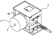
- FIG. 6 is a schematic perspective structural view of a device for unlocking a power-exchange device according to an embodiment of the present invention, which has a casing and a suction device for a power-exchange device.
- Figure 7 is a cross-sectional view of Figure 6.
- Figure 8 is a side elevational view of the casing of the power exchange device unlocking device in accordance with an embodiment of the present invention.
- FIG. 9 is a schematic structural diagram of a power changing device according to an embodiment of the present invention.
- FIG. 10 is a front elevational view of a battery case in a battery box quick change system according to an embodiment of the present invention.
- FIG. 11 is a schematic diagram of a battery box quick change system according to an embodiment of the present invention in which a power exchange device is unlocked near a battery box.
- an embodiment of the present invention provides a power-changing device unlocking device, including: a driving component 1, a transmission mechanism 2, and an unlocking lever 3; the driving component 1 is connected to the transmission mechanism 2, and is driven.
- the mechanism 2 is connected to the unlocking lever 3; the driving element 1 drives the transmission mechanism 2 to move, and the transmission mechanism 2 drives the unlocking lever 3 to expand and contract.
- the power-changing device unlocking device for unlocking the battery box is usually disposed on both sides of the power-changing device, and the power-changing device located on both sides when the power-changing device is docked with the battery box.
- the unlocking device presses the locking bolt locked by the battery box and the battery box fixing bracket from both sides to separate the battery box from the battery box fixing frame.
- the normal power exchange time is about ten minutes, and the power exchange time is also long.
- the device has a compact overall structure, a small volume, and a sensitive action, compared with the previously used power-changing device unlocking device. The most important thing is that the power-changing time is less than six minutes, and the efficiency is improved. Doubled.
- the unlocking lever 3 manipulates its telescopic movement by the driving element 1 and the transmission mechanism 2 disposed at the rear thereof, and the structure of the driving element 1 and the transmission mechanism 2 to satisfy the entire power-changing device unlocking device
- the design is compact and compact.
- the unlocking action only needs to extend the unlocking lever 3 with respect to the unlocking device disposed on both sides, the step less means that the possibility of causing an error during the unlocking process is small, and since the unlocking lever 3 is a kind of lever
- the structure can realize the point-to-point unlocking. As long as the unlocking lever 3 is aligned with the position to be unlocked, the unlocking action can be completed easily and quickly, and the precision is high.
- the transmission mechanism 2 of the present embodiment includes a transmission rod 21, a driving column 22, a driven column 23, a connecting member 24 and a guiding portion 25; one end of the transmission rod 21 is connected to the driving element 1, The other end of the transmission rod 21 is connected to the active column 22, and the connecting member 24 is respectively connected to the active column 22 and the driven column 23.
- the guiding portion 25 is provided with a driven column guiding hole 251 extending in the axial direction of the unlocking rod 3.
- the driven column 23 passes through the driven column guiding hole 251 and slides in the driven column guiding hole 251.
- the guiding portion 25 is provided with an unlocking rod guiding hole 252, and the unlocking rod 3 passes through the unlocking rod guiding hole 252; the connecting member 24 is wound.
- the transmission mechanism 2 is a core component.
- the structure of the transmission mechanism 2 includes five components, wherein the transmission lever 21 is driven by the driving component 1. For generating the force, the active column 22 moves with the transmission rod 21, and the force generated by the transmission rod 21 drives the active column 22 to move.
- the connecting member 24 connects the active column 22 and the driven column 23 together and can be wound around two
- the axis of the person rotates, and the torque generated by the movement of the active column 22 drives the connecting member 24 to rotate around the active column 22 and the driven column 23 at the same time.
- the connecting member 24 generates an edge on the driven column 23 acting on the driven column 23.
- the radial thrust of the driven column 23 in the diametrical direction pushes the driven post 23 to slide in the driven post guiding hole 251 opened on the guiding portion 25, and finally pushes the unlocking lever 3 to perform the telescopic movement in the unlocking lever guiding hole 252.
- the transmission rod 21 is vertically connected to the central portion of the active column 22, and both ends of the active column 22 and the two ends of the driven column 23 are respectively connected by a connecting member 24, and the connecting member 24 and the active column 22 and the slave
- the moving column 23 is pivotally connected, and the driven column 23 passes through the driven column guiding hole 251 on the guiding portion 25, and the guiding portion 25 is located between the two connecting members 24, and the unlocking rod 3 abuts against the middle portion of the driven column 23 and wears
- the unlocking lever guide hole 252 on the guide portion 25 is passed.
- the lateral moment of the transmission rod 21 is converted into the longitudinal moment of the unlocking rod 3 by the linkage of the active column 22 and the driven column 23, thereby saving the space inside the device of the power exchange device, and the driven device is driven.
- the guide portion 25 of the column guide hole 251 is always on the same straight line when the unlocking lever 3 is stretched and contracted, and the unlocking accuracy of the unlocking lever 3 is further improved.
- the guide post 25 of the present embodiment is further provided with an active column guiding hole 253 extending in the axial direction of the transmission rod 21, and the active column 22 passes through the active column guiding hole 253 and is in the active column guiding hole.
- the driven column guiding hole 251 solves the problem of the matching direction of the moving column 23 and the unlocking lever 3 and the expansion and contraction stability of the unlocking lever 3, but in the process of pulling the active column 22 by the transmission rod 21, There is a problem that the force is lost during the transmission due to the indefinite movement direction of the active column 22.
- the active column guiding hole 253 is opened on the guiding portion 25, and the extending direction thereof is the same as the pulling direction of the transmission rod 21, so that the active column 22 During the pulling by the transmission rod 21, the pulling force of the transmission rod 21 is not divided.
- the transmission rod 21 is caused to move in the same straight line through the active column guiding hole 253 during the pulling of the active column 22, thereby avoiding the loss of force during the torque transmission and improving the energy utilization rate. .
- the guide portion 25 of the present embodiment has a first plate body 254, a second plate body 255, and a third plate body 256, and the second plate body 255 is coupled to the first plate body 254 and the third plate body.
- the active column guiding hole 253 is opened on the first plate body 254 and/or the third plate body 256
- the driven column guiding hole 251 is opened on the first plate body 254 and/or the third plate body 256 to unlock
- the rod guiding hole 252 is opened on the second plate body 255.
- the stability of the active column 22, the driven column 23 and the guiding portion 25 is particularly important, so the guiding portion 25 should be designed to be sufficiently strong and not easily activated.
- the displacement of the column 22 and the driven column 23 is affected by the movement of the column 22, so in the present embodiment, the guiding portion 25 is designed as a semi-enclosed structure, and the first plate body 254 and the third plate body 256 are actively supported from above and below.
- the column 22 and the driven column 23, the second plate 255 is supported between the first plate 254 and the third plate 256 in front of the driven column 23, and protects the rear transmission mechanism 2 from the front to avoid external devices.
- the first plate body 254 and the third plate body 256 are provided with a driving column guiding hole 253 and a driven column guiding hole 251.
- the two connecting elements 24 are respectively located on the first plate body 254.
- an outer side of the third plate body 256, the unlocking rod guiding hole 252 is opened on the second plate body 255.
- the entire transmission mechanism 2 can be made more stable without hindering the movement of the transmission rod 21 and the unlocking lever 3.
- the telescopic movement of the unlocking lever 3 is maintained in the horizontal plane, and the unlocking lever 3 is further improved in point-to-point unlocking. Precision.
- the transmission rod 21 includes an active element 211, a force transmitting element 212 and a driven element 213.
- the active element 211 is connected to the driving element 1
- the driven element 213 is connected to the active column 22.
- the force element 212 is movably coupled to the active element 211, and the force transmitting element 212 is fixedly coupled to the driven element 213.
- the single-structure transmission rod 21 not only has the risk of wear and tear after repeated hundreds of thousands of pulling movements, but also, due to the active column guiding hole 253 and the driven column guiding
- the length of the hole 251 is usually not very long.
- the single-structure transmission rod 21 easily causes the stroke of the driving element 1 to be longer than the length of the active column guiding hole 253, so that the stroke of the driving element 1 is not completed and the active column 22 has already been In the case where the abutment is on the inner wall of the active column guide hole 253, the single-structure transmission rod 21 is easily subjected to stress fracture. Therefore, the transmission rod 21 is designed in a three-stage configuration, and the force acting on the driven element 213 is dissipated by the force transmitting member 212, thereby protecting the transmission rod 21.
- the transmission rod 21 adopts a three-part structure, and the strength of the transmission rod 21 can be increased by the intermediate section force transmitting element 212, so that the force of the transmission rod 21 is dispersed in three parts during the torque transmission of the transmission rod 21. Thereby, the transmission rod 21 is protected to prolong the service life during long-term repeated operation.
- the force transmitting element 212 includes a force transmitting piece 2121, a force transmitting spring 2122 and two fixing pieces 2123.
- the two ends of the force transmitting piece 2121 are respectively connected with the active element 211 and the driven element 213.
- the two fixing pieces 2123 are fixed on the force transmitting piece 2121 and connected to the two ends of the force transmitting spring 2122.
- the force transmitting spring 2122 extends along the axial direction of the transmission rod 21, and the transmitting force piece 2121 is provided with a through hole 2124.
- the hole 2124 is located between the two fixing pieces 2123.
- the active element 211 includes an active piece 2111 and a post 2112.
- the driving piece 2111 passes through the two fixing pieces 2123 in sequence and is disposed in the force transmitting spring 2122.
- the sheet 2111 is located between the two fixing pieces 2123.
- One end of the post 2112 extends into the through hole 2124, and the other end of the post 2112 is caught between the two spirals of the force transmitting spring 2122; the driving piece 2111 is along the transmission rod 21 Slide in the axial direction, the post 2112 slides in the through hole 2124.
- the force transmitting element 212 is designed. A structure that combines both buffering and delayed force transmission.
- the active piece 2111, the post 2112 and the force transmitting spring 2122 form a buffer structure.
- the driving element 1 applies a force to the active piece 2111, or when the driven element 213 applies a force to the force transmitting piece 2121, the active piece
- the post 2112 on the 2111 toggles the force transmitting spring 2122, so that the spring between the post 2112 and one fixing piece 2123 is stretched, the spring between the post 2112 and the other fixing piece 2123 contracts, and the force transmitting spring 2122 absorbs.
- the force, the force transmitting piece 2121 is temporarily not applied with a force, and the buffer structure can effectively cope with the sudden force generated when the driving element 1 is turned on and off, so that it can be slowly, uniformly and smoothly transmitted to the next one. component.
- the two fixing pieces 2123, the force transmitting spring 2122, the post 2112, the through hole 2124 and the force transmitting piece 2121 constitute a delayed force transmitting structure, and when the tensioned and compressed spring absorbs the force, due to the spring recovery The force, the stretched spring will pull the fixing piece 2123, the compressed spring will push the fixing piece 2123, the two parts of the spring have the same force in the force of the two fixing pieces 2123, and finally push the force transmitting piece 2121 toward In one direction of motion, since the movement of the force transmitting piece 2121 is slightly later than the movement of the active piece 2111 or the movement of the driven element 213, this structure is called a delayed force transmitting structure.
- a buffer structure composed of the force transmitting spring 2122, the fixing piece 2123, the post 2112 and the through hole 2124 is used to transmit the force of the driving element 1 on the active element 211 when the driving element 1 is in operation.
- the force spring 2122 is stored, and the force is released to the driven element 213 by the restoring force of the force transmitting spring 2122 to create a delay of force transmission, and the protection transmission rod 21 remains when the driving element 1 is turned on or off, or when the frequency is abrupt. It can guarantee the smooth transmission of force.
- the driven member 213 includes a driven piece 2131 and two supporting pieces 2132.
- the driven piece 2131 is connected to the force transmitting element 212, and the two supporting pieces 2132 are respectively connected to the driven piece.
- the joint of the driven element 213 and the active column 22 is worn more and more fragile, and damage is easily generated.
- the driven element 213 and the active component are active.
- Two support plates 2132 for reinforcement are added to the joint of the column 22, so that the driven member 213 is stronger in the process of pulling the active column 22, and the two support pieces 2132 are perpendicular to the axis of the active column 22, and are driven.
- the sheet 2131 is perpendicular to the two support sheets 2132. With the preferred embodiment, the strength of the junction of the drive rod 21 and the active post 22 is enhanced.
- the power-changing device unlocking device of the present embodiment further includes a casing 4, and one end of the unlocking lever 3 connected to the transmission mechanism 2 is located in the casing 4, and the other end of the unlocking lever 3 passes through the casing 4.
- a box 4 having a hardness is surrounded by a weak connection of the transmission mechanism 2, and most of the structure of the transmission mechanism 2 is accommodated therein, leaving only the transmission mechanism 2 and the drive.
- the connection of the more fragile transmission 2 and the release lever 3 is surrounded by a box 4 of strength and stiffness, which serves to protect the transmission 2 and the release lever 3.
- the casing 4 of the present embodiment includes a movable casing 41, a cushioning member 42, and a fixed casing 43, and the fixed casing 43 is fixed, and the movable casing 41 is movably coupled to the fixed casing 43 via the cushioning member 42.
- the casing 4 has two parts, one is a stationary fixed box 43, and the other is a movable box 41 movable relative to the fixed box 43, and the movable box 41 is connected to the transmission mechanism 2 for unlocking the rod 3
- the entire unlocking device is given a buffer to protect the entire unlocking device.
- the transmission mechanism 2 and the unlocking lever 3 are provided with a certain buffer protection function.
- the cushioning member 42 is a cushion spring which extends in the axial direction of the unlocking lever 3.
- two buffer springs are connected at a position between the rear end of the movable case 41 and the fixed case 43, which are disposed in parallel with each other and are respectively located on both sides of the unlocking lever 3 to function as a buffer and balance.
- the smoothness of the expansion and contraction of the movable case 41 is ensured by the cushioning of the spring and the smoothness of the recovery.
- the fixed box 43 is provided with a slide rail 431 extending along the axial direction of the unlocking rod 3, and the movable box 41 is provided with a sliding member 411, and the sliding member 411 is sliding. Slide on the rail 431.
- the present preferred embodiment adds "wheels” and “tracks” to the movable case 41 following the back and forth movement of the buffer spring, that is, the slider 411 and the slide rail 431, which is the sliding direction of the movable case 41 and the expansion and contraction of the unlocking lever 3.
- the direction is the same.
- the direction of the buffering movement of the movable case 41 coincides with the direction of expansion and contraction of the unlocking lever 3, and the accuracy of the point-to-point unlocking of the unlocking lever 3 is further improved.
- the slide rail 431 on the fixing case 43 has an exit hole 432 at its end, and the exit hole 432 has a larger diameter than the inner diameter of the slide rail 431 and the outer diameter of the slider 411.
- the end of the slide rail 431 is designed as an exit hole 432 having a larger aperture, so that the slider 411 can enter and exit the slide rail 431, facilitating assembly of the movable box. 41 and fixing box 43.
- the loading and unloading operation between the movable case 41 and the fixed case 43 is facilitated.
- one end of the transmission mechanism 2 is inserted into the movable box 41, and is connected to the movable box 41 through a connecting member 412.
- the fixed box 43 is provided with a moving passage 433, and a limit notch 413 is formed on the movable box 41, and the limit gap 413 is defined.
- the transmission mechanism 2 sequentially passes through the moving passage 433 and the limit notch 413.
- the transmission mechanism 2 and the movable case 41 are coupled together by providing a connecting member 412 between the second plate body 255 and the inner wall of the movable case 41, and the limit notch 413 guides the transmission mechanism.
- the moving passage 433 functions to support the gravity of the transmission mechanism 2, and on the other hand, it can slide in the same direction when the transmission mechanism 2 is moved backward by the movable casing 41.
- the pulling movement of the transmission rod 21 driven by the driving element 1 is guided by the limiting notch 413, and the overall displacement along the telescopic direction of the unlocking rod 3 does not occur, while the transmission rod 21 is carried out together with the movable box 41.
- the cushioning movement is not affected by the fixing box 43.
- the present invention provides a power changing device, comprising: a battery tray and a power-changing device unlocking device as described above; a battery tray is provided with a casing 5 and a power-exchange device suction cup 6, and the power-changing device unlocking device is provided.
- the power exchange device suction cup 6 is connected to the outer casing 5 through the power exchange device unlocking device, the power exchange device suction cup 6 is sleeved on the unlocking lever 3, and the unlocking lever 3 is telescoped in the power exchange device suction cup 6.
- the power changing device of the embodiment integrates the unlocking lever 3 into the power feeding device suction cup 6, so that the power changing device can complete the battery box by using the unlocking lever 3 while docking with the battery box 7 by using the power changing device suction cup 6.
- the unlocking action of the electric device suction cup 6 can protect the unlocking rod 3 from being broken during the expansion and contraction of the unlocking rod 3 by using the thick structure thereof, and can also guide the unlocking rod 3 to expand and contract in one direction, thereby further improving the precision.
- the end portion of the unlocking lever 3 away from the transmission mechanism 2 is provided with a flange 31, and the corresponding flange 31 of the power changing device suction cup 6 is provided with a convex portion.
- the table 61 has a flange 31 that is shaped to match the boss 61. Specifically, the cooperation of the boss 61 and the flange 31 serves as a retreating action for the unlocking lever 3, so that the unlocking lever 3 is not excessively retracted, so that the next unlocking operation cannot be completely completed, thereby affecting the power-changing efficiency. problem. With the preferred embodiment, the unlocking lever 3 is prevented from retracting into the suction cup during retraction, affecting the next unlocking operation.
- the end surface of the unlocking lever 3 is flush with the surface of the power receiving device suction cup 6. With the preferred embodiment, it is possible to protect the end of the unlocking lever 3 from damage.
- the present invention provides a battery box 7 quick change system including: a battery case 7, a battery case holder (not shown), and a power changing device as described above;
- the case 7 includes a lock tongue 71 and an unlock button 72.
- the unlock button 72 is interlocked with the lock tongue 71.
- the unlock button 72 is disposed corresponding to the unlocking lever 3; the battery case holder has a locking portion (not shown), the lock tongue 71 and the lock The locking engagement of the stop; the extended movement of the unlocking lever 3 is for pressing the unlocking button 72 to drive the locking tongue 71 to exit the locking portion to unlock.
- an unlock button 72 associated with the lock tongue 71 is disposed on the battery case 7 corresponding to the unlocking lever 3, and in actual application, the unlocking lever 3 is extended.
- the unlock button 72 is pressed, the lock tongue 71 is retracted into the battery case 7, and the battery case 7 and the battery case holder are unlocked.
- the lock tongue 71 is reset, and the unlocking lever 3 is unlocked.
- the whole operation process is very convenient, and the unlocking precision is also high.
- the unlocking button 72 is sleeved with a battery box suction cup 73 and the unlocking button 72 is telescoped in the battery box suction cup 73, and the battery box suction cup 73 is replaced with the battery.
- the device suction cup 6 is correspondingly set.
- the battery case suction cup 73 and the power exchange device suction cup 6 are both electromagnet suction cups, and the battery box 7 of the preferred embodiment is used for the quick change system, and the power exchange device and the battery box 7 are passed.
- the magnetic force generated by the suction cup 6 of the electric power changing device and the suction cup 73 of the battery box are attracted to each other.
- the driving element 1 in the electric switching device is opened, the transmission mechanism 2 is pulled back, and the unlocking rod 3 is extended to extend the suction device 6 of the electric device, and the unlocking lever is released.
- the unlock button 72 in the battery box suction cup 73 is opened.
- the unlock button 72 drives the lock tongue 71 to retract the lock box, the battery box 7 is unlocked from the battery box holder, and then the power changing device utilizes two suction cups still stuck together.
- the two steps together are the power exchange process of the battery box 7 quick change system.
- the quick change system of the battery box 7 of the embodiment adopts a single box for power exchange, and the overall structure of the device is compact, the action is sensitive, and the power exchange time is less than 6 minutes, realizing full automatic control.
- the power exchange device suction cup 6 and the movable case 41 are connected together by an insulating plate 62 to shield the current when the power exchange device suction cup 6 is energized.
- the unlocking lever 3 can accurately unlock the unlocking button 72 point-to-point, and the unlocking precision thereof The high value does not cause the battery box 7 to be completely unlocked, so that the entire power-changing unlocking system is locked, and the power-changing efficiency of the power-changing system is improved.
- the power exchange device unlocking device, the power changing device and the battery box 7 quick change system provided by the invention transmit the torque of the driving component 1 to the unlocking lever 3 by using the transmission mechanism 2, so that the point-to-point precise telescopic unlocking and unlocking precision can be realized.
- the high and high unlocking accuracy also saves a part of the time when the power-changing device is unlocked, thereby improving the power-changing efficiency.
Landscapes
- Engineering & Computer Science (AREA)
- Mechanical Engineering (AREA)
- Transportation (AREA)
- Power Engineering (AREA)
- Chemical & Material Sciences (AREA)
- Combustion & Propulsion (AREA)
- Arrangement Or Mounting Of Propulsion Units For Vehicles (AREA)
- Battery Mounting, Suspending (AREA)
- Secondary Cells (AREA)
Abstract
一种换电设备解锁装置、换电设备及电池箱快速换电系统,换电设备解锁装置中,驱动元件(1)与传动机构(2)连接并驱动其运动,传动机构(2)与解锁杆(3)连接并带动其伸缩。换电设备中,电池托盘上设有外壳(5)和换电设备吸盘(6),换电设备解锁装置设于外壳(5)中,换电设备吸盘(6)通过换电设备解锁装置与外壳(5)连接,换电设备吸盘(6)套设在解锁杆(3)上且解锁杆(3)在换电设备吸盘(6)中伸缩。电池箱快速换电系统中,电池箱(7)包括连动的锁舌(71)和解锁按钮(72),解锁按钮(72)与解锁杆(3)对应设置;电池箱固定架具有与锁舌(71)锁定配合的锁止部;解锁杆(3)的伸出运动用于按下解锁按钮(72),带动锁舌(71)退出锁止部解锁。该换电设备解锁装置、换电设备及电池箱快速换电系统解锁精度高、换电效率高。
Description
本申请要求申请日为2017年12月29日的中国专利申请CN201711486870.4的优先权。本申请引用上述中国专利申请的全文。
本发明涉及电池箱换电设备领域,特别涉及一种换电设备解锁装置、电池箱快速换电系统及换电机器人。
由于石油资源的紧张和人们日趋加强的环境保护意识,电动车的使用越来越广泛,并且已经成为了一种潮流。而为配合电动车的使用,换电站也应运而生,在换电站中,通过换电机器人实现对电动车的电池箱的快速换电。
现有技术中,换电机器人中用于将电动车的电池箱从电动车中拆卸分离的解锁装置采用的是吸盘和解锁机构分离的结构,即用于与电池箱连接的吸盘设置在解锁装置与电池箱对接的表面,解锁机构则分设在解锁装置的两侧,当吸盘与电池箱连接时,解锁机构分别将电池箱两侧的锁止机构解锁,从而完成电池箱的拆卸动作。然而,在实际使用过程中,这种结构的解锁精度较差,会发生解锁不完全而造成换电机器人无法将电池箱拉出的问题,这也一定程度上影响了换电机器人的换电效率。
发明内容
本发明要解决的技术问题是为了克服现有技术中换电机器人在换电过程中解锁精度差、换电效率差的缺陷,提供一种换电设备解锁装置、电池箱快速换电系统及换电机器人。
本发明是通过下述技术方案来解决上述技术问题:
一种换电设备解锁装置,其包括有:驱动元件、传动机构和解锁杆;所述驱动元件与所述传动机构连接,所述传动机构与所述解锁杆连接;所述驱动元件驱动所述传动机构运动,所述传动机构带动所述解锁杆伸缩。
较佳地,在本发明的换电设备解锁装置中,所述传动机构包括传动杆、主动柱、从动柱、连接元件和导向部;所述传动杆的一端与所述驱动元件连接,所述传动杆的另一端与所述主动柱连接,所述连接元件分别与所述主动柱和所述从动柱连接,所述导向部上 开设有沿所述解锁杆的轴向方向延伸的从动柱导向孔,所述从动柱穿过所述从动柱导向孔并于所述从动柱导向孔中滑动,所述导向部上设有解锁杆导向孔,所述解锁杆穿过所述解锁杆导向孔;所述连接元件绕所述主动柱的轴线转动,所述连接元件绕所述从动柱的轴线转动,所述解锁杆绕所述从动柱的轴线转动。通过本优选实施方案,采用主动柱与从动柱的联动,将传动杆的横向力矩转换成解锁杆的纵向力矩,节约了换电设备解说装置内部的空间,利用开设有从动柱导向孔的导向部保持解锁杆伸缩时始终处于同一直线上,进一步提高了解锁杆的解锁精度。
较佳地,在本发明的换电设备解锁装置中,所述导向部上还开设有沿所述传动杆的轴向方向延伸的主动柱导向孔,所述主动柱穿过所述主动柱导向孔并于所述主动柱导向孔中滑动。通过本优选实施方案,使得传动杆在拉动主动柱的过程中通过一个主动柱导向孔使其运动始终处于同一直线上,避免了在力矩传递过程中的力损失,提高了能源利用率。
较佳地,在本发明的换电设备解锁装置中,所述导向部具有第一板体、第二板体和第三板体,所述第二板体连接在所述第一板体和所述第三板体之间,所述主动柱导向孔开设在所述第一板体和/或所述第三板体上,所述从动柱导向孔开设在所述第一板体和/或所述第三板体上,所述解锁杆导向孔开设在所述第二板体上。通过本优选实施方案,能够在不妨碍传动杆、解锁杆的运动的前提下,使得整个传动机构更加稳定,解锁杆的伸缩运动保持在水平面内,进一步提高解锁杆点对点解锁的精确度。
较佳地,在本发明的换电设备解锁装置中,所述传动杆包括主动元件、传力元件和从动元件,所述主动元件与所述驱动元件连接,所述从动元件与所述主动柱连接,所述传力元件与所述主动元件活动连接,所述传力元件与所述从动元件固定连接。通过本优选实施方案,传动杆采用三部分结构,通过中间段传力元件可以给提高传动杆的强度,使在传动杆的力矩传递过程中传动杆的受力分散在三个部分,从而保护传动杆,延长在长期反复作业过程中的使用寿命。
较佳地,在本发明的换电设备解锁装置中,所述传力元件包括传力片、传力弹簧和两个固定片,所述传力片的两端分别连接所述主动元件和所述从动元件,两个所述固定片固定在所述传力片上且连接在所述传力弹簧的两端,所述传力弹簧沿所述传动杆的轴向方向延伸,所述传力片上设有通孔,所述通孔位于两个所述固定片之间;所述主动元件包括主动片和卡柱,所述主动片依次穿过两个所述固定片且穿设在所述传力弹簧中,所述卡柱连接在所述主动片上且位于两个所述固定片之间,所述卡柱的一端伸入所述通孔,所述卡柱的另一端卡在所述传力弹簧的两个螺旋之间;所述主动片沿所述传动杆的 轴向方向上滑动,所述卡柱在所述通孔中滑动。通过本优选实施方案,利用传力弹簧、固定片、卡柱和通孔组成的缓冲结构,在驱动元件运转时,将驱动元件施加在主动元件上的作用力通过传力弹簧储存,再通过传力弹簧的回复力将该作用力释放给从动元件,制造一个力传递的延迟,保护传动杆在驱动元件开启或关闭时、或者频率突变时依然能够保证平稳地传递作用力。
较佳地,在本发明的换电设备解锁装置中,所述从动元件包括从动片和两个支撑片,所述从动片与所述传力元件连接,两个所述支撑片分别连接在所述从动片沿所述主动柱的轴向方向的两边,两个所述支撑片分别连接在所述主动柱上。通过本优选实施方案,加强了传动杆与主动柱的连接处的强度。
较佳地,在本发明的换电设备解锁装置中,所述换电设备解锁装置还包括盒体,所述解锁杆与所述传动机构连接的一端位于所述盒体内,所述解锁杆的另一端穿出所述盒体。通过本优选实施方案,利用一个具有强度和硬度的盒体包围较为脆弱的传动机构和解锁杆的连接处,起到保护传动机构和解锁杆的作用。
较佳地,在本发明的换电设备解锁装置中,所述盒体包括活动盒、缓冲元件和固定盒,所述固定盒固定,所述活动盒通过所述缓冲元件活动连接在所述固定盒内。通过本优选实施方案,对传动机构、解锁杆起到一定的缓冲保护作用。
较佳地,在本发明的换电设备解锁装置中,所述缓冲元件是缓冲弹簧,所述缓冲弹簧沿所述解锁杆的轴向方向延伸。通过本优选实施方案,利用弹簧的缓冲和回复的平稳性保证活动盒伸缩的平稳。
较佳地,在本发明的换电设备解锁装置中,所述固定盒上设有滑轨,所述滑轨沿所述解锁杆的轴向方向延伸,所述活动盒上设有滑动件,所述滑动件在所述滑轨上滑动。通过本优选实施方案,使活动盒的缓冲运动方向与解锁杆的伸缩方向一致,进一步提高解锁杆点对点解锁的精度。
较佳地,在本发明的换电设备解锁装置中,所述滑轨的端部具有退出孔,所述退出孔的孔径大于所述滑轨的内径和所述滑动件的外径。通过本优选实施方案,方便活动盒与固定盒之间的装卸操作。
较佳地,在本发明的换电设备解锁装置中,所述传动机构伸入所述活动盒的一端与所述活动盒通过连接部件连接,所述固定盒上设有移动通道,所述活动盒上开设有限位缺口,所述限位缺口与所述移动通道连通,所述传动机构依次穿过所述移动通道和所述限位缺口。通过本优选实施方案,使得传动杆受驱动元件驱动的牵拉运动被限位缺口引导,不会发生沿解锁杆伸缩方向的整体位移,同时传动杆在与活动盒一同进行缓冲运动 时不受固定盒的影响。
一种换电设备,其包括有:电池托盘;如前文所述的换电设备解锁装置;所述电池托盘上设有外壳和换电设备吸盘,所述换电设备解锁装置设于所述外壳中,所述换电设备吸盘通过所述换电设备解锁装置与所述外壳连接,所述换电设备吸盘套设在所述解锁杆上且所述解锁杆在所述换电设备吸盘中伸缩。
较佳地,在本发明的换电设备中,所述解锁杆远离所述传动机构的端部上设有凸缘,在所述换电设备吸盘中对应所述凸缘设有凸台,所述凸缘与所述凸台形状匹配。通过本优选实施方案,防止解锁杆在缩回的过程中缩入吸盘中,影响下一次解锁操作。
较佳地,在本发明的换电设备中,所述解锁杆的端面与所述换电设备吸盘的表面齐平。通过本优选实施方案,能够保护解锁杆伸出的端头不受损坏。
一种电池箱快速换电系统,其包括有:电池箱、电池箱固定架及如前文所述的换电设备;所述电池箱包括锁舌和解锁按钮,所述解锁按钮与所述锁舌连动,所述解锁按钮与所述解锁杆对应设置;所述电池箱固定架具有锁止部,所述锁舌和所述锁止部锁定配合;所述解锁杆的伸出运动用于按下所述解锁按钮,带动所述锁舌退出所述锁止部解锁。
较佳地,在本发明的电池箱快速换电系统中,所述解锁按钮上套设有电池箱吸盘且所述解锁按钮在所述电池箱吸盘中伸缩,所述电池箱吸盘与所述换电设备吸盘对应设置。通过本优选实施方案,在换电设备与电池箱通过换电设备吸盘和电池箱吸盘互相吸引贴合在一起时,解锁杆能够精确地对解锁按钮进行点对点解锁,其解锁精度高,不会造成电池箱不完全解锁而使整个换电解锁系统卡止的问题,提高了换电系统的换电效率。。
在符合本领域常识的基础上,上述各优选条件,可任意组合,即得本发明各较佳实例。
本发明的积极进步效果在于:
本发明提供的换电设备解锁装置、换电设备及电池箱快速换电系统,利用传动机构将驱动元件的力矩传递给解锁杆,使其能够实现点对点的精确伸缩解锁,解锁精度高,高解锁精度同时也会省去一部分换电设备解锁的时间,从而提高了换电效率。
图1为本发明一实施例的换电设备解锁装置的立体图。
图2为本发明一实施例的换电设备解锁装置的侧视图。
图3为本发明一实施例的换电设备解锁装置的传动机构的平面图。
图4为本发明一实施例的换电设备解锁装置的导向部的结构图。
图5为本发明一实施例的换电设备解锁装置的传动杆的结构图。
图6为本发明一实施例的换电设备解锁装置中具有盒体和换电设备吸盘时的立体结构示意图。
图7为图6的横截面图。
图8为本发明一实施例的换电设备解锁装置中盒体的侧视图。
图9为本发明一实施例的换电设备的结构示意图。
图10为本发明一实施例的电池箱快速换电系统中电池箱的主视图。
图11为本发明一实施例的电池箱快速换电系统中换电设备接近电池箱进行解锁时的示意图。
附图标记说明:
驱动元件1;传动机构2;传动杆21;主动元件211;主动片2111;卡柱2112;传力元件212;传力片2121;传力弹簧2122;固定片2123;通孔2124;从动元件213;从动片2131;支撑片2132;主动柱22;从动柱23;连接元件24;导向部25;从动柱导向孔251;解锁杆导向孔252;主动柱导向孔253;第一板体254;第二板体255;第三板体256;解锁杆3;凸缘31;盒体4;活动盒41;滑动件411;连接部件412;限位缺口413;缓冲元件42;固定盒43;滑轨431;退出孔432;移动通道433;外壳5;换电设备吸盘6;凸台61;绝缘板62;电池箱7;锁舌71;解锁按钮72;电池箱吸盘73
下面举个较佳实施例,并结合附图来更清楚完整地说明本发明。
在本发明的描述中,需要理解的是,术语“上”、“下”、“前”、“后”、“左”、“右”、“竖直”、“水平”、“顶”、“底”、“内”、“外”等指示的方位或位置关系为基于附图所示的方位或位置关系,仅是为了便于描述本发明和简化描述,而不是指示或暗示所指的装置或元件必须具有特定的方位、以特定的方位构造和操作,因此不能理解为对本发明的限制。
如图1和图2所示,本发明的实施例提供了一种换电设备解锁装置,其包括有:驱动元件1、传动机构2和解锁杆3;驱动元件1与传动机构2连接,传动机构2与解锁杆3连接;驱动元件1驱动传动机构2运动,传动机构2带动解锁杆3伸缩。
具体来说,在混合动力汽车换电站中,用于解锁电池箱的换电设备解锁装置通常设置在换电设备的两侧,在换电设备与电池箱对接时,位于两侧的换电设备解锁装置从两侧按压电池箱与电池箱固定架锁定的锁舌以使电池箱从电池箱固定架上分离,通常的换电时间约为十分钟,换电时间也较长。在本实施例的换电设备解锁装置中,相比原先使 用的换电设备解锁装置,设备整体结构紧凑,体积不大,动作灵敏,最重要的是换电时间小于六分钟,效率提高了近一倍。在本实施例的换电设备解锁装置中,解锁杆3通过设置在其后方的驱动元件1和传动机构2操纵其伸缩运动,驱动元件1和传动机构2的结构以满足整个换电设备解锁装置的结构紧凑、小巧为目的进行设计。相对于设置于两侧的解锁装置,解锁动作只需要将解锁杆3伸出即可完成,步骤少意味着在进行解锁过程中造成误差的可能性小,并且,由于解锁杆3是一种杆状结构,能够实现点对点的解锁,只要将解锁杆3对准需要解锁的位置,就能既轻松、又迅速地完成解锁动作,并且精度还高。
如图2和图3所示,在本实施例的传动机构2包括传动杆21、主动柱22、从动柱23、连接元件24和导向部25;传动杆21的一端与驱动元件1连接,传动杆21的另一端与主动柱22连接,连接元件24分别与主动柱22和从动柱23连接,导向部25上开设有沿解锁杆3的轴向方向延伸的从动柱导向孔251,从动柱23穿过从动柱导向孔251并于从动柱导向孔251中滑动,导向部25上设有解锁杆导向孔252,解锁杆3穿过解锁杆导向孔252;连接元件24绕主动柱22的轴线转动,连接元件24绕从动柱23的轴线转动,解锁杆3绕从动柱23的轴线转动。具体来说,传动机构2是核心部件,为实现本发明的目的,在本实施例的换电设备解锁装置中,传动机构2的结构包括了五个部件,其中传动杆21被驱动元件1驱动,用于产生作用力,主动柱22随着传动杆21运动,传动杆21产生的作用力带动主动柱22运动,由于连接元件24将主动柱22和从动柱23连接在一起且能绕两者的轴线转动,主动柱22运动产生的转矩带动连接元件24同时绕主动柱22和从动柱23转动,此时连接元件24在从动柱23上产生作用于从动柱23上的沿从动柱23的直径方向的径向推力,推动从动柱23在开设在导向部25上的从动柱导向孔251中滑动,最终推动解锁杆3在解锁杆导向孔252中作伸缩运动。在本实施例中,传动杆21垂直连接在主动柱22的中部,主动柱22的两端和从动柱23的两端分别通过一个连接元件24连接,连接元件24分别与主动柱22和从动柱23枢接,从动柱23穿过导向部25上的从动柱导向孔251,导向部25位于两个连接元件24之间,解锁杆3抵顶于从动柱23的中部且穿过导向部25上的解锁杆导向孔252。通过本优选实施方案,采用主动柱22与从动柱23的联动,将传动杆21的横向力矩转换成解锁杆3的纵向力矩,节约了换电设备解说装置内部的空间,利用开设有从动柱导向孔251的导向部25保持解锁杆3伸缩时始终处于同一直线上,进一步提高了解锁杆3的解锁精度。
如图4所示,在本实施例的导向部25上还开设有沿传动杆21的轴向方向延伸的主动柱导向孔253,主动柱22穿过主动柱导向孔253并于主动柱导向孔253中滑动。具体 来说,从动柱导向孔251解决了从动柱23和解锁杆3的运动方向匹配问题和解锁杆3的伸缩稳定性问题,但在传动杆21拉动主动柱22的过程中,依然会存在因主动柱22的运动方向不定而导致力在传递过程中发生损失的问题,因此,在导向部25上开设主动柱导向孔253,其延伸方向同传动杆21的拉动方向,使得主动柱22在被传动杆21拉动的过程中,传动杆21的拉力不会被分力。通过本优选实施方案,使得传动杆21在拉动主动柱22的过程中通过一个主动柱导向孔253使其运动始终处于同一直线上,避免了在力矩传递过程中的力损失,提高了能源利用率。
如图4所示,在本实施例的导向部25具有第一板体254、第二板体255和第三板体256,第二板体255连接在第一板体254和第三板体256之间,主动柱导向孔253开设在第一板体254和/或第三板体256上,从动柱导向孔251开设在第一板体254和/或第三板体256上,解锁杆导向孔252开设在第二板体255上。具体来说,在驱动元件1驱动传动杆21进行拉伸解锁的操作时,主动柱22、从动柱23和导向部25的稳定性尤为重要,因此导向部25应当设计得足够牢固不易被主动柱22和从动柱23的运动影响而发生位移,故在本实施例中,导向部25设计成一种半包围的结构,第一板体254和第三板体256从上方和下方支撑着主动柱22和从动柱23,第二板体255在从动柱23的前方支在第一板体254和第三板体256中间,并且从前方保护后方的传动机构2,避免在与外部设备接触的时候造成内部的传动机构2的磨损,解锁杆3穿过第二板体255,但不与第二板体255连接,其能够自由地作伸缩运动。在本实施例的一个优选方案中,第一板体254和第三板体256上都开设有主动柱导向孔253和从动柱导向孔251,两个连接元件24分别位于第一板体254和第三板体256外侧,解锁杆导向孔252则开设在第二板体255上。通过本优选实施方案,能够在不妨碍传动杆21、解锁杆3的运动的前提下,使得整个传动机构2更加稳定,解锁杆3的伸缩运动保持在水平面内,进一步提高解锁杆3点对点解锁的精度。
如图5所示,在传动机构2中,传动杆21包括主动元件211、传力元件212和从动元件213,主动元件211与驱动元件1连接,从动元件213与主动柱22连接,传力元件212与主动元件211活动连接,传力元件212与从动元件213固定连接。具体来说,在实际工作过程中,单根结构的传动杆21不仅在重复上百上千次牵拉运动后会发生磨损导致断裂的危险,而且,由于主动柱导向孔253和从动柱导向孔251的长度通常不会很长,因此,单根结构的传动杆21很容易发生驱动元件1的行程大于主动柱导向孔253的长度,造成驱动元件1的行程未走完而主动柱22已经抵顶在主动柱导向孔253的内壁上的情况,很容易使单根结构的传动杆21发生应力性断裂。因此,将传动杆21设计成三段 结构,通过传力元件212将作用于从动元件213的力消解掉,起到保护传动杆21的作用。通过本优选实施方案,传动杆21采用三部分结构,通过中间段传力元件212可以给提高传动杆21的强度,使在传动杆21的力矩传递过程中传动杆21的受力分散在三个部分,从而保护传动杆21,延长在长期反复作业过程中的使用寿命。
如图5所示,在传动杆21中,传力元件212包括传力片2121、传力弹簧2122和两个固定片2123,传力片2121的两端分别连接主动元件211和从动元件213,两个固定片2123固定在传力片2121上且连接在传力弹簧2122的两端,传力弹簧2122沿传动杆21的轴向方向延伸,传力片2121上设有通孔2124,通孔2124位于两个固定片2123之间;主动元件211包括主动片2111和卡柱2112,主动片2111依次穿过两个固定片2123且穿设在传力弹簧2122中,卡柱2112连接在主动片2111上且位于两个固定片2123之间,卡柱2112的一端伸入通孔2124,卡柱2112的另一端卡在传力弹簧2122的两个螺旋之间;主动片2111沿传动杆21的轴向方向上滑动,卡柱2112在通孔2124中滑动。具体来说,为了最大限度地保护传动杆21并且保证传动杆21的牵拉运动、主动柱22和从动柱23的滑动、解锁杆3的伸缩运动能够平稳且均衡,把传力元件212设计成兼具缓冲和延迟传力功能的结构。其中,主动片2111、卡柱2112和传力弹簧2122组成一个缓冲结构,当驱动元件1给主动片2111施加作用力时,或者当从动元件213给传力片2121施加作用力时,主动片2111上的卡柱2112拨动传力弹簧2122,使得卡柱2112与一个固定片2123之间的弹簧拉伸,卡柱2112与另一个固定片2123之间的弹簧收缩,传力弹簧2122会吸收该作用力,传力片2121上暂时不会被施加作用力,该缓冲结构能够有效地应对驱动元件1开启和关闭时突然产生的作用力,使其能够缓慢、均匀、平稳地传递给下一个部件。同时两个固定片2123、传力弹簧2122、卡柱2112、通孔2124和传力片2121组成一个延迟传力结构,当被拉伸和被压缩的弹簧吸收了作用力后,由于弹簧的回复力,被拉伸的弹簧会拉拽固定片2123,被压缩的弹簧会推开固定片2123,两个部分的弹簧对两个固定片2123的作用力的方向相同,最终推动传力片2121朝一个方向运动,由于传力片2121的运动会稍晚于主动片2111的运动或从动元件213的运动,因此这一结构被称为延迟传力结构。通过本优选实施方案,利用传力弹簧2122、固定片2123、卡柱2112和通孔2124组成的缓冲结构,在驱动元件1运转时,将驱动元件1施加在主动元件211上的作用力通过传力弹簧2122储存,再通过传力弹簧2122的回复力将该作用力释放给从动元件213,制造一个力传递的延迟,保护传动杆21在驱动元件1开启或关闭时、或者频率突变时依然能够保证平稳地传递作用力。
如图5所示,在传动杆21中,从动元件213包括从动片2131和两个支撑片2132, 从动片2131与传力元件212连接,两个支撑片2132分别连接在从动片2131沿主动柱22的轴向方向的两边,两个支撑片2132分别连接在主动柱22上。具体来说,在多次反复牵拉主动柱22的运动中,从动元件213与主动柱22的连接处磨损较大较为脆弱,很容易发生损坏,本实施例中在从动元件213与主动柱22的连接处增加了两个用于加固的支撑片2132,使得从动元件213在牵拉主动柱22的过程中强度更高,两个支撑片2132与主动柱22的轴线垂直,从动片2131与两个支撑片2132垂直。通过本优选实施方案,加强了传动杆21与主动柱22的连接处的强度。
如图6所示,本实施例的换电设备解锁装置还包括盒体4,解锁杆3与传动机构2连接的一端位于盒体4内,解锁杆3的另一端穿出盒体4。具体来说,在本优选方案中,在传动机构2较为脆弱的连接处外包围着一个具有硬度的盒体4,将传动机构2的大部分结构收纳于其中,仅留下传动机构2与驱动元件1的连接端以及解锁杆3的伸出端。通过本优选实施方案,利用一个具有强度和硬度的盒体4包围较为脆弱的传动机构2和解锁杆3的连接处,起到保护传动机构2和解锁杆3的作用。
如图7所示,本实施例的盒体4包括活动盒41、缓冲元件42和固定盒43,固定盒43固定,活动盒41通过缓冲元件42活动连接在固定盒43内。具体来说,盒体4具有两个部分,一个是固定不动的固定盒43,一个是可相对于固定盒43活动的活动盒41,活动盒41与传动机构2连接,用于当解锁杆3进行点对点解锁时,给予整个解锁装置以缓冲,对整个解锁装置进行保护。通过本优选实施方案,对传动机构2、解锁杆3起到一定的缓冲保护作用。
如图7所示,在本实施例中,缓冲元件42是缓冲弹簧,缓冲弹簧沿解锁杆3的轴向方向延伸。具体来说,在活动盒41的后端与固定盒43之间的位置连接两根缓冲弹簧,互相平行设置且分别位于解锁杆3的两侧,起到缓冲和平衡的作用。通过本优选实施方案,利用弹簧的缓冲和回复的平稳性保证活动盒41伸缩的平稳。
如图8所示,在盒体4中,固定盒43上设有滑轨431,滑轨431沿解锁杆3的轴向方向延伸,活动盒41上设有滑动件411,滑动件411在滑轨431上滑动。具体来说,本优选实施方案给跟随缓冲弹簧前后运动的活动盒41增设了“轮子”和“轨道”,即滑动件411和滑轨431,是活动盒41的滑动方向与解锁杆3的伸缩方向一致。通过本优选实施方案,使活动盒41的缓冲运动方向与解锁杆3的伸缩方向一致,进一步提高解锁杆3点对点解锁的精度。
如图8所示,固定盒43上的滑轨431,其端部具有退出孔432,退出孔432的孔径大于滑轨431的内径和滑动件411的外径。具体来说,为方便组装和拆卸活动盒41与固 定盒43,将滑轨431的端部设计成具有更大孔径的退出孔432,便于滑动件411进入和退出滑轨431,利于组装活动盒41和固定盒43。通过本优选实施方案,方便活动盒41与固定盒43之间的装卸操作。
如图7所示,传动机构2伸入活动盒41的一端与活动盒41通过连接部件412连接,固定盒43上设有移动通道433,活动盒41上开设有限位缺口413,限位缺口413与移动通道433连通,传动机构2依次穿过移动通道433和限位缺口413。具体来说,在本优选实施方案中,通过在第二板体255和活动盒41的内壁之间设置一个连接部件412将传动机构2和活动盒41连接在一起,限位缺口413引导传动机构2的牵拉运动,移动通道433一方面起到支撑传动机构2的重力的作用,另一方面能够在传动机构2因活动盒41受力向后运动压缩弹簧时能够沿同一方向滑动。通过本优选实施方案,使得传动杆21受驱动元件1驱动的牵拉运动被限位缺口413引导,不会发生沿解锁杆3伸缩方向的整体位移,同时传动杆21在与活动盒41一同进行缓冲运动时不受固定盒43的影响。
如图9所示,本发明提供了一种换电设备,包括:电池托盘及如前文描述的换电设备解锁装置;电池托盘上设有外壳5和换电设备吸盘6,换电设备解锁装置设于外壳5中,换电设备吸盘6通过换电设备解锁装置与外壳5连接,换电设备吸盘6套设在解锁杆3上且解锁杆3在换电设备吸盘6中伸缩。
具体来说,本实施例的换电设备将解锁杆3整合入换电设备吸盘6中,使得换电设备在利用换电设备吸盘6与电池箱7对接的同时能够利用解锁杆3完成电池箱7的解锁动作,同时换电设备吸盘6利用其厚实的结构能够在解锁杆3伸缩的过程中保护解锁杆3避免其断裂,还能够起到引导解锁杆3沿一个方向伸缩,进一步提高精度。
如图7和图9所示,在本实施例的换电设备中,解锁杆3远离传动机构2的端部上设有凸缘31,在换电设备吸盘6中对应凸缘31设有凸台61,凸缘31与凸台61形状匹配。具体来说,凸台61和凸缘31的配合起到对解锁杆3的止退作用,使解锁杆3不会因为过度缩回而导致下一次的解锁操作无法完全完成以致影响换电效率的问题。通过本优选实施方案,防止解锁杆3在缩回的过程中缩入吸盘中,影响下一次解锁操作。
如图7所示,在本实施例的换电设备中,解锁杆3的端面与换电设备吸盘6的表面齐平。通过本优选实施方案,能够保护解锁杆3伸出的端头不受损坏。
如图10和图11所示,本发明提供了一种电池箱7快速换电系统,其包括有:电池箱7、电池箱固定架(未示出)及如前文描述的换电设备;电池箱7包括锁舌71和解锁按钮72,解锁按钮72与锁舌71连动,解锁按钮72与解锁杆3对应设置;电池箱固定架具有锁止部(未示出),锁舌71和锁止部锁定配合;解锁杆3的伸出运动用于按下解锁 按钮72,带动锁舌71退出锁止部解锁。
具体来说,在本实施例的电池箱7快速换电系统中,对应于解锁杆3在电池箱7上设置了与锁舌71联动的解锁按钮72,在实际应用中,解锁杆3伸出按压解锁按钮72,锁舌71缩入电池箱7,电池箱7和电池箱固定架即解除锁定,在将电池箱7从电池箱固定架中分离后,锁舌71复位,解锁杆3被解锁按钮72顶回换电设备中,整个操作过程非常方便,解锁精度也很高。
如图11所示,在本实施例的电池箱7快速换电系统中,解锁按钮72上套设有电池箱吸盘73且解锁按钮72在电池箱吸盘73中伸缩,电池箱吸盘73与换电设备吸盘6对应设置。具体来说,在本实施例中,电池箱吸盘73和换电设备吸盘6均为电磁铁吸盘,使用本优选实施方案的电池箱7快速换电系统,换电设备与电池箱7通过通了电换电设备吸盘6和电池箱吸盘73产生的磁力互相吸引连接,此时换电设备中的驱动元件1开启,拉回传动机构2,带动解锁杆3伸出换电设备吸盘6,解锁杆3点下电池箱吸盘73中的解锁按钮72,解锁按钮72带动锁舌71缩回锁盒,电池箱7遂从电池箱固定架上解锁,接着换电设备利用仍旧吸附在一起的两个吸盘的吸力将电池箱7拉出电池箱固定架,从而完成电池箱7与电池箱固定架的分离作业,然后驱动元件1将传动机构2推出,在从动柱23与解锁杆3之间留有间隙,由于锁舌71的回复力解锁按钮72将解锁杆3推回换电设备吸盘6,最后电池箱吸盘73和换电设备吸盘6断电,电池箱7与换电设备分离,完成电池箱7的拆卸工作。将上述步骤反过来操作一遍,就能够将电池箱7从换电站中装入汽车中。两个步骤合起来就是电池箱7快速换电系统的换电过程。本实施例的电池箱7快速换电系统采用单箱换电,设备整体结构紧凑,动作灵敏,换电时间小于6分钟,实现了全自动化控制。在本实施例的一个优选实施方案中,换电设备吸盘6和活动盒41之间通过一个绝缘板62连接在一起,屏蔽换电设备吸盘6通电时的电流。通过本优选实施方案,在换电设备与电池箱7通过换电设备吸盘6和电池箱吸盘73互相吸引贴合在一起时,解锁杆3能够精确地对解锁按钮72进行点对点解锁,其解锁精度高,不会造成电池箱7不完全解锁而使整个换电解锁系统卡止的问题,提高了换电系统的换电效率。
本发明提供的换电设备解锁装置、换电设备及电池箱7快速换电系统,利用传动机构2将驱动元件1的力矩传递给解锁杆3,使其能够实现点对点的精确伸缩解锁,解锁精度高,高解锁精度同时也会省去一部分换电设备解锁的时间,从而提高了换电效率。
虽然以上描述了本发明的具体实施方式,但是本领域的技术人员应当理解,这仅是举例说明,本发明的保护范围是由所附权利要求书限定的。本领域的技术人员在不背离本发明的原理和实质的前提下,可以对这些实施方式做出多种变更或修改,但这些变更 和修改均落入本发明的保护范围。
Claims (18)
- 一种换电设备解锁装置,其特征在于,其包括有:驱动元件、传动机构和解锁杆;所述驱动元件与所述传动机构连接,所述传动机构与所述解锁杆连接;所述驱动元件驱动所述传动机构运动,所述传动机构带动所述解锁杆伸缩。
- 如权利要求1所述的换电设备解锁装置,其特征在于,所述传动机构包括传动杆、主动柱、从动柱、连接元件和导向部;所述传动杆的一端与所述驱动元件连接,所述传动杆的另一端与所述主动柱连接,所述连接元件分别与所述主动柱和所述从动柱连接,所述导向部上开设有沿所述解锁杆的轴向方向延伸的从动柱导向孔,所述从动柱穿过所述从动柱导向孔并于所述从动柱导向孔中滑动,所述导向部上设有解锁杆导向孔,所述解锁杆穿过所述解锁杆导向孔;所述连接元件绕所述主动柱的轴线转动,所述连接元件绕所述从动柱的轴线转动,所述解锁杆绕所述从动柱的轴线转动。
- 如权利要求2所述的换电设备解锁装置,其特征在于,所述导向部上还开设有沿所述传动杆的轴向方向延伸的主动柱导向孔,所述主动柱穿过所述主动柱导向孔并于所述主动柱导向孔中滑动。
- 如权利要求3所述的换电设备解锁装置,其特征在于,所述导向部具有第一板体、第二板体和第三板体,所述第二板体连接在所述第一板体和所述第三板体之间,所述主动柱导向孔开设在所述第一板体和/或所述第三板体上,所述从动柱导向孔开设在所述第一板体和/或所述第三板体上,所述解锁杆导向孔开设在所述第二板体上。
- 如权利要求2-4中至少一项所述的换电设备解锁装置,其特征在于,所述传动杆包括主动元件、传力元件和从动元件,所述主动元件与所述驱动元件连接,所述从动元件与所述主动柱连接,所述传力元件与所述主动元件活动连接,所述传力元件与所述从动元件固定连接。
- 如权利要求5所述的换电设备解锁装置,其特征在于:所述传力元件包括传力片、传力弹簧和两个固定片,所述传力片的两端分别连接所述主动元件和所述从动元件,两个所述固定片固定在所述传力片上且连接在所述传力弹簧的两端,所述传力弹簧沿所述传动杆的轴向方向延伸,所述传力片上设有通孔,所述通孔位于两个所述固定片之间;所述主动元件包括主动片和卡柱,所述主动片依次穿过两个所述固定片且穿设在所 述传力弹簧中,所述卡柱连接在所述主动片上且位于两个所述固定片之间,所述卡柱的一端伸入所述通孔,所述卡柱的另一端卡在所述传力弹簧的两个螺旋之间;所述主动片沿所述传动杆的轴向方向上滑动,所述卡柱在所述通孔中滑动。
- 如权利要求5或6所述的换电设备解锁装置,其特征在于,所述从动元件包括从动片和两个支撑片,所述从动片与所述传力元件连接,两个所述支撑片分别连接在所述从动片沿所述主动柱的轴向方向的两边,两个所述支撑片分别连接在所述主动柱上。
- 如权利要求1-7中至少一项所述的换电设备解锁装置,其特征在于,所述换电设备解锁装置还包括盒体,所述解锁杆与所述传动机构连接的一端位于所述盒体内,所述解锁杆的另一端穿出所述盒体。
- 如权利要求8所述的换电设备解锁装置,其特征在于,所述盒体包括活动盒、缓冲元件和固定盒,所述固定盒固定,所述活动盒通过所述缓冲元件活动连接在所述固定盒内。
- 如权利要求9所述的换电设备解锁装置,其特征在于,所述缓冲元件是缓冲弹簧,所述缓冲弹簧沿所述解锁杆的轴向方向延伸。
- 如权利要求9或10所述的换电设备解锁装置,其特征在于,所述固定盒上设有滑轨,所述滑轨沿所述解锁杆的轴向方向延伸,所述活动盒上设有滑动件,所述滑动件在所述滑轨上滑动。
- 如权利要求11所述的换电设备解锁装置,其特征在于,所述滑轨的端部具有退出孔,所述退出孔的孔径大于所述滑轨的内径和所述滑动件的外径。
- 如权利要求9-12中至少一项所述的换电设备解锁装置,其特征在于,所述传动机构伸入所述活动盒的一端与所述活动盒通过连接部件连接,所述固定盒上设有移动通道,所述活动盒上开设有限位缺口,所述限位缺口与所述移动通道连通,所述传动机构依次穿过所述移动通道和所述限位缺口。
- 一种换电设备,其特征在于,其包括有:电池托盘;如权利要求1至13任一项所述的换电设备解锁装置;所述电池托盘上设有外壳和换电设备吸盘,所述换电设备解锁装置设于所述外壳中,所述换电设备吸盘通过所述换电设备解锁装置与所述外壳连接,所述换电设备吸盘套设在所述解锁杆上且所述解锁杆在所述换电设备吸盘中伸缩。
- 如权利要求14所述的换电设备,其特征在于,所述解锁杆远离所述传动机构的端部上设有凸缘,在所述换电设备吸盘中对应所述凸缘设有凸台,所述凸缘与所述凸台 形状匹配。
- 如权利要求14或15所述的换电设备,其特征在于,所述解锁杆的端面与所述换电设备吸盘的表面齐平。
- 一种电池箱快速换电系统,其特征在于,其包括有:电池箱、电池箱固定架及如权利要求14至16任一项所述的换电设备;所述电池箱包括锁舌和解锁按钮,所述解锁按钮与所述锁舌连动,所述解锁按钮与所述解锁杆对应设置;所述电池箱固定架具有锁止部,所述锁舌和所述锁止部锁定配合;所述解锁杆的伸出运动用于按下所述解锁按钮,带动所述锁舌退出所述锁止部解锁。
- 如权利要求17所述的电池箱快速换电系统,其特征在于,所述解锁按钮上套设有电池箱吸盘且所述解锁按钮在所述电池箱吸盘中伸缩,所述电池箱吸盘与所述换电设备吸盘对应设置。
Priority Applications (3)
| Application Number | Priority Date | Filing Date | Title |
|---|---|---|---|
| MYPI2020003308A MY188851A (en) | 2017-12-29 | 2018-12-29 | Battery replacement device unlocking apparatus, battery replacement device and battery box quick battery replacement system |
| SG11202006164TA SG11202006164TA (en) | 2017-12-29 | 2018-12-29 | Battery replacement device unlocking apparatus, battery replacement device and battery box quick battery replacement system |
| PH12020550998A PH12020550998A1 (en) | 2017-12-29 | 2020-06-26 | Battery replacement device unlocking apparatus, battery replacement device and battery box quick battery replacement system |
Applications Claiming Priority (2)
| Application Number | Priority Date | Filing Date | Title |
|---|---|---|---|
| CN201711486870.4A CN109987069B (zh) | 2017-12-29 | 2017-12-29 | 换电设备及电池箱快速换电系统 |
| CN201711486870.4 | 2017-12-29 |
Publications (1)
| Publication Number | Publication Date |
|---|---|
| WO2019129284A1 true WO2019129284A1 (zh) | 2019-07-04 |
Family
ID=67063255
Family Applications (1)
| Application Number | Title | Priority Date | Filing Date |
|---|---|---|---|
| PCT/CN2018/125675 Ceased WO2019129284A1 (zh) | 2017-12-29 | 2018-12-29 | 换电设备解锁装置、换电设备及电池箱快速换电系统 |
Country Status (5)
| Country | Link |
|---|---|
| CN (4) | CN109987069B (zh) |
| MY (1) | MY188851A (zh) |
| PH (1) | PH12020550998A1 (zh) |
| SG (1) | SG11202006164TA (zh) |
| WO (1) | WO2019129284A1 (zh) |
Cited By (12)
| Publication number | Priority date | Publication date | Assignee | Title |
|---|---|---|---|---|
| CN110978980A (zh) * | 2019-12-19 | 2020-04-10 | 北自精工机械(常州)有限公司 | 一种汽车电池的锁止机构 |
| CN111361445A (zh) * | 2020-03-25 | 2020-07-03 | 广东博智林机器人有限公司 | 一种电池拆装装置及移动底盘 |
| CN112389179A (zh) * | 2020-10-10 | 2021-02-23 | 东风汽车集团有限公司 | 一种车辆电池包加解锁装置及总成 |
| CN112599912A (zh) * | 2019-09-16 | 2021-04-02 | 奥动新能源汽车科技有限公司 | 磁盘吸附式锁机构及包括其的电池包 |
| CN112706650A (zh) * | 2020-12-30 | 2021-04-27 | 国网智慧能源交通技术创新中心(苏州)有限公司 | 一种电池箱的限位锁止机构 |
| CN113043905A (zh) * | 2021-05-12 | 2021-06-29 | 安徽华菱汽车有限公司 | 一种纯电动重卡换电系统锁止机构 |
| CN113119707A (zh) * | 2019-12-31 | 2021-07-16 | 奥动新能源汽车科技有限公司 | 用于电池包的锁止机构、快换支架组件及电动汽车 |
| CN113320710A (zh) * | 2021-05-28 | 2021-08-31 | 重庆师范大学 | 一种航拍云台全自动电池更换基站 |
| CN113415207A (zh) * | 2021-08-09 | 2021-09-21 | 安徽华菱汽车有限公司 | 一种纯电动重卡换电系统液压锁止机构 |
| CN115303048A (zh) * | 2021-12-31 | 2022-11-08 | 奥动新能源汽车科技有限公司 | 换电设备的解锁检测装置、充换电站和可换电的船舶 |
| CN115303117A (zh) * | 2022-04-02 | 2022-11-08 | 奥动新能源汽车科技有限公司 | 解锁杆升降检测装置及换电设备 |
| CN115723960A (zh) * | 2022-11-21 | 2023-03-03 | 海航航空技术有限公司 | 一种飞机表面清洗时用的静压孔保护装置 |
Families Citing this family (8)
| Publication number | Priority date | Publication date | Assignee | Title |
|---|---|---|---|---|
| CN111823945A (zh) * | 2020-06-23 | 2020-10-27 | 常州皓瑞能源科技有限公司 | 一种电池箱快速锁止机构 |
| CN113895287B (zh) * | 2020-07-06 | 2024-08-06 | 奥动新能源汽车科技有限公司 | 解锁装置及包含其的换电设备 |
| CN115972883B (zh) * | 2021-12-31 | 2025-12-30 | 奥动新能源股份有限公司 | 换电设备的解锁装置、充换电站和可换电的船舶 |
| CN115556619A (zh) * | 2022-01-24 | 2023-01-03 | 深圳市亿威汽车科技有限公司 | 一种高可靠度重卡换电总成 |
| CN114639858B (zh) * | 2022-04-08 | 2023-04-07 | 苏州市华盛源机电有限公司 | 一种新能源汽车电池包下层壳体的智能对接加工设备 |
| CN115306227B (zh) * | 2022-07-22 | 2023-10-20 | 东风柳州汽车有限公司 | 一种电磁锁装置 |
| WO2025067489A1 (zh) * | 2023-09-28 | 2025-04-03 | 奥动新能源汽车科技有限公司 | 解锁装置、换电设备及换电小车 |
| CN120236987B (zh) * | 2025-06-03 | 2025-08-22 | 浙江中科尚弘离子装备工程有限公司 | 一种离子注入机中的解锁顶升组件 |
Citations (7)
| Publication number | Priority date | Publication date | Assignee | Title |
|---|---|---|---|---|
| WO2010004192A2 (fr) * | 2008-07-08 | 2010-01-14 | Renault S.A.S. | Dispositif de verrouillage et de deverrouillage automatiques d'un bac batterie de vehicule automobile electrique, vehicule et station d'echange de batteries equipes d'un tel dispositif |
| CN102180200A (zh) * | 2011-05-30 | 2011-09-14 | 柳崇禧 | 用于电动汽车的车载移动式自动充换电站及电池快换方法 |
| CN202200959U (zh) * | 2011-08-31 | 2012-04-25 | 昆明船舶设备集团有限公司 | 一种电动客车电池箱锁紧与解锁装置 |
| CN102616216A (zh) * | 2011-01-30 | 2012-08-01 | 北京市电力公司 | 电池箱锁止机构、电池箱及机械手 |
| CN102729959A (zh) * | 2011-04-15 | 2012-10-17 | 贵阳普天物流技术有限公司 | 一种更换电池箱的方法及换电夹具 |
| CN103619623A (zh) * | 2011-06-20 | 2014-03-05 | 株式会社丰田自动织机 | 车辆用电池单元安装装置 |
| CN106494370A (zh) * | 2016-12-30 | 2017-03-15 | 上海电巴新能源科技有限公司 | 解锁装置、换电移动平台和快换系统 |
Family Cites Families (13)
| Publication number | Priority date | Publication date | Assignee | Title |
|---|---|---|---|---|
| JPH10144392A (ja) * | 1996-11-14 | 1998-05-29 | Sumitomo Wiring Syst Ltd | 電気自動車のチャージ用コネクタ |
| JP4091853B2 (ja) * | 2003-01-31 | 2008-05-28 | 小島プレス工業株式会社 | 両開きドア開閉装置 |
| KR101313279B1 (ko) * | 2011-06-01 | 2013-09-30 | 국민대학교산학협력단 | 전기자동차의 배터리 교환 방법 |
| CN102343894B (zh) * | 2011-08-31 | 2013-03-20 | 昆明船舶设备集团有限公司 | 滑入式底部取电可自锁的电动客车电池快换托盘装置 |
| CN102392564A (zh) * | 2011-10-24 | 2012-03-28 | 苏州润邦电气有限公司 | 一种电池箱开锁装置 |
| CN102392560B (zh) * | 2011-11-09 | 2013-10-23 | 希美克(广州)实业有限公司 | 一种可换向锁体 |
| CN102529667B (zh) * | 2012-02-15 | 2015-09-02 | 亿源动力(北京)科技有限公司 | 车用电池箱的锁定装置 |
| CN202480855U (zh) * | 2012-03-28 | 2012-10-10 | 贵阳普天物流技术有限公司 | 车载电池箱的锁紧装置 |
| CN103192690B (zh) * | 2013-04-10 | 2016-01-27 | 北京汽车股份有限公司 | 发动机悬置安装点解锁装置及汽车 |
| CN103507785B (zh) * | 2013-09-18 | 2015-08-05 | 深圳精智机器有限公司 | 换电设备 |
| CN104724082B (zh) * | 2013-12-20 | 2017-04-12 | 国家电网公司 | 电池箱体锁止装置 |
| CN105041061B (zh) * | 2015-08-14 | 2017-07-11 | 中国航空工业集团公司西安飞机设计研究所 | 一种舱门解锁装置及具有其的舱门 |
| CN205601588U (zh) * | 2016-03-03 | 2016-09-28 | 上海电巴新能源科技有限公司 | 一种大巴电池包解锁机构 |
-
2017
- 2017-12-29 CN CN201711486870.4A patent/CN109987069B/zh active Active
- 2017-12-29 CN CN202111601555.8A patent/CN114312460B/zh active Active
- 2017-12-29 CN CN202111598734.0A patent/CN114161987B/zh active Active
- 2017-12-29 CN CN202111599137.XA patent/CN114084038B/zh active Active
-
2018
- 2018-12-29 WO PCT/CN2018/125675 patent/WO2019129284A1/zh not_active Ceased
- 2018-12-29 SG SG11202006164TA patent/SG11202006164TA/en unknown
- 2018-12-29 MY MYPI2020003308A patent/MY188851A/en unknown
-
2020
- 2020-06-26 PH PH12020550998A patent/PH12020550998A1/en unknown
Patent Citations (7)
| Publication number | Priority date | Publication date | Assignee | Title |
|---|---|---|---|---|
| WO2010004192A2 (fr) * | 2008-07-08 | 2010-01-14 | Renault S.A.S. | Dispositif de verrouillage et de deverrouillage automatiques d'un bac batterie de vehicule automobile electrique, vehicule et station d'echange de batteries equipes d'un tel dispositif |
| CN102616216A (zh) * | 2011-01-30 | 2012-08-01 | 北京市电力公司 | 电池箱锁止机构、电池箱及机械手 |
| CN102729959A (zh) * | 2011-04-15 | 2012-10-17 | 贵阳普天物流技术有限公司 | 一种更换电池箱的方法及换电夹具 |
| CN102180200A (zh) * | 2011-05-30 | 2011-09-14 | 柳崇禧 | 用于电动汽车的车载移动式自动充换电站及电池快换方法 |
| CN103619623A (zh) * | 2011-06-20 | 2014-03-05 | 株式会社丰田自动织机 | 车辆用电池单元安装装置 |
| CN202200959U (zh) * | 2011-08-31 | 2012-04-25 | 昆明船舶设备集团有限公司 | 一种电动客车电池箱锁紧与解锁装置 |
| CN106494370A (zh) * | 2016-12-30 | 2017-03-15 | 上海电巴新能源科技有限公司 | 解锁装置、换电移动平台和快换系统 |
Cited By (17)
| Publication number | Priority date | Publication date | Assignee | Title |
|---|---|---|---|---|
| CN112599912A (zh) * | 2019-09-16 | 2021-04-02 | 奥动新能源汽车科技有限公司 | 磁盘吸附式锁机构及包括其的电池包 |
| CN110978980A (zh) * | 2019-12-19 | 2020-04-10 | 北自精工机械(常州)有限公司 | 一种汽车电池的锁止机构 |
| CN113119707A (zh) * | 2019-12-31 | 2021-07-16 | 奥动新能源汽车科技有限公司 | 用于电池包的锁止机构、快换支架组件及电动汽车 |
| CN111361445A (zh) * | 2020-03-25 | 2020-07-03 | 广东博智林机器人有限公司 | 一种电池拆装装置及移动底盘 |
| CN111361445B (zh) * | 2020-03-25 | 2022-10-28 | 广东博智林机器人有限公司 | 一种电池拆装装置及移动底盘 |
| CN112389179A (zh) * | 2020-10-10 | 2021-02-23 | 东风汽车集团有限公司 | 一种车辆电池包加解锁装置及总成 |
| CN112389179B (zh) * | 2020-10-10 | 2022-04-26 | 东风汽车集团有限公司 | 一种车辆电池包加解锁装置及总成 |
| CN112706650A (zh) * | 2020-12-30 | 2021-04-27 | 国网智慧能源交通技术创新中心(苏州)有限公司 | 一种电池箱的限位锁止机构 |
| CN113043905B (zh) * | 2021-05-12 | 2024-04-26 | 安徽华菱汽车有限公司 | 一种纯电动重卡换电系统锁止机构 |
| CN113043905A (zh) * | 2021-05-12 | 2021-06-29 | 安徽华菱汽车有限公司 | 一种纯电动重卡换电系统锁止机构 |
| CN113320710A (zh) * | 2021-05-28 | 2021-08-31 | 重庆师范大学 | 一种航拍云台全自动电池更换基站 |
| CN113320710B (zh) * | 2021-05-28 | 2022-09-09 | 重庆师范大学 | 一种航拍云台全自动电池更换基站 |
| CN113415207A (zh) * | 2021-08-09 | 2021-09-21 | 安徽华菱汽车有限公司 | 一种纯电动重卡换电系统液压锁止机构 |
| CN113415207B (zh) * | 2021-08-09 | 2024-05-03 | 安徽华菱汽车有限公司 | 一种纯电动重卡换电系统液压锁止机构 |
| CN115303048A (zh) * | 2021-12-31 | 2022-11-08 | 奥动新能源汽车科技有限公司 | 换电设备的解锁检测装置、充换电站和可换电的船舶 |
| CN115303117A (zh) * | 2022-04-02 | 2022-11-08 | 奥动新能源汽车科技有限公司 | 解锁杆升降检测装置及换电设备 |
| CN115723960A (zh) * | 2022-11-21 | 2023-03-03 | 海航航空技术有限公司 | 一种飞机表面清洗时用的静压孔保护装置 |
Also Published As
| Publication number | Publication date |
|---|---|
| CN109987069B (zh) | 2021-11-12 |
| CN114312460B (zh) | 2023-12-29 |
| CN114084038A (zh) | 2022-02-25 |
| CN109987069A (zh) | 2019-07-09 |
| CN114161987B (zh) | 2023-12-29 |
| CN114312460A (zh) | 2022-04-12 |
| MY188851A (en) | 2022-01-10 |
| SG11202006164TA (en) | 2020-07-29 |
| PH12020550998A1 (en) | 2021-03-22 |
| CN114161987A (zh) | 2022-03-11 |
| CN114084038B (zh) | 2023-05-30 |
Similar Documents
| Publication | Publication Date | Title |
|---|---|---|
| WO2019129284A1 (zh) | 换电设备解锁装置、换电设备及电池箱快速换电系统 | |
| EP3733465B1 (en) | Battery case and quick battery case replacement system | |
| CN110001596B (zh) | 用于电池包的解锁装置及包含其的锁机构和换电设备 | |
| CN104724082B (zh) | 电池箱体锁止装置 | |
| WO2019129288A1 (zh) | 锁止机构、锁止系统、快换支架组件及电动汽车 | |
| CN104724078B (zh) | 电池箱体锁止装置 | |
| JP2018172217A (ja) | ジブ格納のためのジブ連結システム | |
| CN113328026B (zh) | 一种大功率led芯片封装装置 | |
| CN223486360U (zh) | 一种驱动头组件、盒和图像形成设备 | |
| CN203623637U (zh) | 电池箱体锁止装置 | |
| CN219115413U (zh) | 拨动式解锁机构和换电设备 | |
| CN217611057U (zh) | 动物承载装置及动物成像设备 | |
| CN203623636U (zh) | 电池箱体锁止装置 | |
| CN114701395B (zh) | 框架结构及车辆 | |
| CN111641065B (zh) | 伸缩传动机构及电子装置扩充座 | |
| US9095055B2 (en) | Electronic device having extendable and retractable sliding member | |
| TWM404581U (en) | Positioning mechanism and related loading system | |
| CN223725329U (zh) | 一种轨道行走机构的齿轮动力解锁装置 | |
| JP7021143B2 (ja) | 引戸 | |
| CN208528908U (zh) | 一种f夹夹具 | |
| CN114348305B (zh) | 一种空间在轨转盘限位机构及其组装方法 | |
| CN218769659U (zh) | 一种电池包装配工装 | |
| CN120139595A (zh) | 一种按压式锁具结构 | |
| CN213869366U (zh) | 一种保险柜锁联动结构 | |
| CN117791029A (zh) | 一种电池包 |
Legal Events
| Date | Code | Title | Description |
|---|---|---|---|
| 121 | Ep: the epo has been informed by wipo that ep was designated in this application |
Ref document number: 18895585 Country of ref document: EP Kind code of ref document: A1 |
|
| NENP | Non-entry into the national phase |
Ref country code: DE |
|
| 122 | Ep: pct application non-entry in european phase |
Ref document number: 18895585 Country of ref document: EP Kind code of ref document: A1 |
|
| WWG | Wipo information: grant in national office |
Ref document number: 202228060763 Country of ref document: IN |