WO2019124308A1 - 固体アルカリ形燃料電池の発電方法 - Google Patents
固体アルカリ形燃料電池の発電方法 Download PDFInfo
- Publication number
- WO2019124308A1 WO2019124308A1 PCT/JP2018/046345 JP2018046345W WO2019124308A1 WO 2019124308 A1 WO2019124308 A1 WO 2019124308A1 JP 2018046345 W JP2018046345 W JP 2018046345W WO 2019124308 A1 WO2019124308 A1 WO 2019124308A1
- Authority
- WO
- WIPO (PCT)
- Prior art keywords
- cathode
- solid electrolyte
- electrolyte body
- fuel cell
- inorganic solid
- Prior art date
- Legal status (The legal status is an assumption and is not a legal conclusion. Google has not performed a legal analysis and makes no representation as to the accuracy of the status listed.)
- Ceased
Links
Images
Classifications
-
- H—ELECTRICITY
- H01—ELECTRIC ELEMENTS
- H01M—PROCESSES OR MEANS, e.g. BATTERIES, FOR THE DIRECT CONVERSION OF CHEMICAL ENERGY INTO ELECTRICAL ENERGY
- H01M8/00—Fuel cells; Manufacture thereof
- H01M8/10—Fuel cells with solid electrolytes
- H01M8/1007—Fuel cells with solid electrolytes with both reactants being gaseous or vaporised
-
- H—ELECTRICITY
- H01—ELECTRIC ELEMENTS
- H01M—PROCESSES OR MEANS, e.g. BATTERIES, FOR THE DIRECT CONVERSION OF CHEMICAL ENERGY INTO ELECTRICAL ENERGY
- H01M8/00—Fuel cells; Manufacture thereof
- H01M8/08—Fuel cells with aqueous electrolytes
- H01M8/083—Alkaline fuel cells
-
- H—ELECTRICITY
- H01—ELECTRIC ELEMENTS
- H01M—PROCESSES OR MEANS, e.g. BATTERIES, FOR THE DIRECT CONVERSION OF CHEMICAL ENERGY INTO ELECTRICAL ENERGY
- H01M8/00—Fuel cells; Manufacture thereof
- H01M8/10—Fuel cells with solid electrolytes
- H01M8/1016—Fuel cells with solid electrolytes characterised by the electrolyte material
-
- H—ELECTRICITY
- H01—ELECTRIC ELEMENTS
- H01M—PROCESSES OR MEANS, e.g. BATTERIES, FOR THE DIRECT CONVERSION OF CHEMICAL ENERGY INTO ELECTRICAL ENERGY
- H01M2300/00—Electrolytes
- H01M2300/0017—Non-aqueous electrolytes
- H01M2300/0065—Solid electrolytes
- H01M2300/0068—Solid electrolytes inorganic
-
- Y—GENERAL TAGGING OF NEW TECHNOLOGICAL DEVELOPMENTS; GENERAL TAGGING OF CROSS-SECTIONAL TECHNOLOGIES SPANNING OVER SEVERAL SECTIONS OF THE IPC; TECHNICAL SUBJECTS COVERED BY FORMER USPC CROSS-REFERENCE ART COLLECTIONS [XRACs] AND DIGESTS
- Y02—TECHNOLOGIES OR APPLICATIONS FOR MITIGATION OR ADAPTATION AGAINST CLIMATE CHANGE
- Y02E—REDUCTION OF GREENHOUSE GAS [GHG] EMISSIONS, RELATED TO ENERGY GENERATION, TRANSMISSION OR DISTRIBUTION
- Y02E60/00—Enabling technologies; Technologies with a potential or indirect contribution to GHG emissions mitigation
- Y02E60/30—Hydrogen technology
- Y02E60/50—Fuel cells
Definitions
- the present invention relates to a power generation method of a solid alkaline fuel cell.
- Alkaline fuel cells are known as fuel cells operating at relatively low temperatures (eg, 250 ° C. or less).
- various liquid fuels or gaseous fuels can be used, for example, the following electrochemical reactions occur when fueled by methanol.
- LDH has a general formula [M 2 + 1 ⁇ x M 3 + x (OH) 2 ] [A n ⁇ x / n ⁇ m H 2 O] (M 2+ is a divalent cation, and M 3+ is a trivalent cation. It is an ion, and An- is an n-valent anion.
- the LDH has a layered structure in which anions and water corresponding to the second half of the general formula are held between double hydroxide layers corresponding to the first half of the general formula.
- the double hydroxide layer is formed by solid solution of a trivalent metal ion in a divalent metal hydroxide, and has a positive charge.
- the anions between the layers have a negative charge to compensate for the positive charge of the double hydroxide layer.
- the present invention has been made based on the above-mentioned new findings, and an object of the present invention is to provide a power generation method of a solid alkaline fuel cell capable of improving power generation capacity.
- the power generation method for a solid alkaline fuel cell comprises an inorganic material comprising a cathode, an anode, and the layered double hydroxide disposed between the cathode and the anode and having hydroxide ion conductivity.
- a power generation method for a solid alkaline fuel cell comprising a solid electrolyte body, characterized in that the cathode side surface of the inorganic solid electrolyte body is exposed to a carbon dioxide containing atmosphere of 600 ppm or more and 20000 ppm or less.
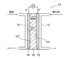
- Sectional view schematically showing the structure of a solid alkaline fuel cell An exploded perspective view of a solid alkaline fuel cell according to an embodiment
- Solid alkaline fuel cell 10 Solid alkaline fuel cell 10
- the solid alkaline fuel cell 10 is a type of alkaline fuel cell (AFC) operating at a relatively low temperature.
- the operating temperature of the solid alkaline fuel cell 10 according to the present embodiment is 50 ° C. to 250 ° C.
- the solid alkaline fuel cell 10 is operated by, for example, methanol, and generates electric power by the following electrochemical reaction.
- cathode 12 3 / 2O 2 + 3H 2 O + 6e - ⁇ 6OH -
- Anode 14 CH 3 OH + 6OH - ⁇ 6e - + CO 2 + 5H 2 O ⁇ All: CH 3 OH + 3 / 2O 2 ⁇ CO 2 + 2H 2 O
- FIG. 1 is a cross-sectional view schematically showing the structure of a solid alkaline fuel cell 10. As shown in FIG.
- the solid alkaline fuel cell 10 comprises a cathode 12, an anode 14 and an inorganic solid electrolyte body 16.
- the cathode 12 is an anode generally called an air electrode.
- the cathode 12 is supplied with an oxidant containing oxygen (O 2 ) via the oxidant supply means 13.
- Air can be used as the oxidant.
- water H 2 O
- the oxidizing agent for example, air, humidified air or the like can be used.
- water (H 2 O) may be any of water vapor in a gas state, water in a liquid state, and a gas-liquid mixture of water vapor and water.
- the cathode 12 is not particularly limited as long as it contains a known cathode catalyst used in an alkaline fuel cell.
- the loading amount of the catalyst on the cathode 12 is not particularly limited, but preferably 0.1 to 10 mg / cm 2 , more preferably 0.1 to 5 mg / cm 2 .
- the cathode catalyst is preferably supported on carbon.
- Preferred examples of the cathode 12 and the catalyst constituting it include platinum-supporting carbon (Pt / C), palladium-supporting carbon (Pd / C), rhodium-supporting carbon (Rh / C), nickel-supporting carbon (Ni / C), Copper-supported carbon (Cu / C) and silver-supported carbon (Ag / C) can be mentioned.
- the method for producing the cathode 12 is not particularly limited.
- the cathode catalyst and optionally the carrier are mixed with a binder to form a paste, and this paste-like mixture is applied to one surface of the inorganic solid electrolyte body 16. Just do it.
- the anode 14 is a cathode generally called a fuel electrode.
- fuel is supplied to the anode 14 via the fuel supply means 15.
- the fuel may be in the form of either liquid fuel or gaseous fuel.
- the fuel compound itself may be a liquid, or a solid fuel compound may be dissolved in a liquid such as water or alcohol.
- Examples of the fuel compound include (i) hydrazine (NH 2 NH 2 ), hydrazine hydrate (NH 2 NH 2 ⁇ H 2 O), hydrazine carbonate ((NH 2 NH 2 ) 2 CO 2 ), hydrazine sulfate (NH 2 ) Hydrazines such as 2 NH 2 ⁇ H 2 SO 4 ), monomethylhydrazine (CH 3 NHNH 2 ), dimethylhydrazine ((CH 3 ) 2 NNH 2 , CH 3 NHNHCH 3 ), and carboxylic hydrazide ((NHNH 2 ) 2 CO) , (Ii) urea (NH 2 CONH 2 ), (iii) ammonia (NH 3 ), (iv) imidazole, 1,3,5-triazine, 3-amino-1,2,4-triazole, etc. class compounds, (v) hydroxylamine (NH 2 OH), hydro such as sulfuric hydroxylamine (NH 2 OH ⁇ H 2 SO
- compounds containing no carbon that is, hydrazine, hydrazine hydrate, hydrazine sulfate, ammonia, hydroxylamine sulfate, hydroxylamine sulfate, etc.
- compounds containing no carbon that is, hydrazine, hydrazine hydrate, hydrazine sulfate, ammonia, hydroxylamine sulfate, hydroxylamine sulfate, etc.
- the fuel compound may be used as a fuel as it is, but may be used as a solution dissolved in water and / or alcohol (for example, lower alcohol such as methanol, ethanol, propanol, isopropanol etc.).
- alcohol for example, lower alcohol such as methanol, ethanol, propanol, isopropanol etc.
- hydrazine, hydrazine hydrate, monomethylhydrazine and dimethylhydrazine are liquids, and thus can be used as they are as liquid fuel.
- hydrazine carbonate, hydrazine sulfate, carbon hydrazide, urea, imidazole, and 3-amino-1,2,4-triazole, and hydroxylamine sulfate are solid but soluble in water.
- 1,3,5-Triazine and hydroxylamine are solid but soluble in alcohol.
- Ammonia is gaseous but soluble in water.
- a solid fuel compound can be dissolved in water or alcohol and used as a liquid fuel.
- the concentration of the fuel compound in the solution is, for example, 1 to 90% by weight, preferably 1 to 30% by weight.
- hydrocarbon-based liquid fuels containing alcohols and ethers such as methanol and ethanol
- hydrocarbon-based gases such as methane
- pure hydrogen can be used as fuels as they are.
- methanol is suitable as the fuel used for the solid alkaline fuel cell 10 according to the present embodiment.
- Methanol may be in any of a gaseous state, a liquid state, and a gas-liquid mixed state.
- the anode 14 is not particularly limited as long as it contains a known anode catalyst used in an alkaline fuel cell.
- anode catalysts include metal catalysts such as Pt, Ni, Co, Fe, Ru, Sn, and Pd.
- the metal catalyst is preferably supported on a support such as carbon, but may be in the form of an organometallic complex having a metal atom of the metal catalyst as a central metal, and such an organometallic complex may be supported as a support. Good.
- a diffusion layer made of a porous material or the like may be disposed on the surface of the anode catalyst.
- Preferred examples of the anode 14 and the catalyst constituting the anode 14 include nickel, cobalt, silver, platinum-supporting carbon (Pt / C), palladium-supporting carbon (Pd / C), rhodium-supporting carbon (Rh / C), nickel-supporting carbon (Ni / C), copper-supported carbon (Cu / C), and silver-supported carbon (Ag / C).
- the method for producing the anode 14 is not particularly limited.
- the anode catalyst and optionally the carrier are mixed with a binder to form a paste, and this paste-like mixture is applied to the surface of the inorganic solid electrolyte body 16 opposite to the cathode 12 It may be formed by
- the inorganic solid electrolyte body 16 is disposed between the cathode 12 and the anode 14.
- the inorganic solid electrolyte body 16 has a cathode side surface 16S and an anode side surface 16T.
- the cathode side surface 16 ⁇ / b> S is a region of the outer surface of the inorganic solid electrolyte body 16 exposed to a space in which the cathode 12 is disposed, and faces the cathode 12.
- the anode side surface 16T is a region of the outer surface of the inorganic solid electrolyte body 16 exposed to a space in which the anode 14 is disposed, and faces the anode 14.
- the inorganic solid electrolyte body 16 is composed of layered double hydroxide (hereinafter referred to as “LDH”) having hydroxide ion conductivity.
- LDH layered double hydroxide
- the inorganic solid electrolyte body 16 exhibits excellent heat resistance and durability as compared with the case where an organic material such as AEM (anion exchange membrane) is used as an electrolyte.
- AEM anion exchange membrane
- the hydroxide ion conductivity of the inorganic solid electrolyte body 16 is preferably as high as possible, but is typically 10 -4 to 10 -1 S / m.
- LDH has a general formula: [M 2 + 1 ⁇ x M 3 + x (OH) 2 ] [A n ⁇ x / n ⁇ m H 2 O] (wherein, M 2+ is a divalent cation, and M 3+ is It is a trivalent cation, A n ⁇ is an n valent anion, n is an integer of 1 or more, and x has a basic composition represented by 0.1 to 0.4.
- the LDH has a layered structure in which anions and water corresponding to the second half of the general formula are held between double hydroxide layers corresponding to the first half of the general formula.
- the double hydroxide layer is formed by solid solution of a trivalent metal ion in a divalent metal hydroxide, and has a positive charge.
- the anions between the layers have a negative charge to compensate for the positive charge of the double hydroxide layer.
- M 2+ may be any divalent cation, but preferred examples include Mg 2+ , Ca 2+ and Zn 2+ , more preferably Mg 2+ .
- M 3+ may be any trivalent cation, but preferred examples include Al 3+ or Cr 3+ , more preferably Al 3+ .
- An - can be any anion, but preferred examples include OH - and CO 3 2- .
- M 2+ comprises Mg 2+, include M 3+ is Al 3+, A n-is OH - and / or CO 3 contain 2- is particularly preferred.
- n is an integer of 1 or more, preferably 1 or 2.
- x is 0.1 to 0.4, preferably 0.2 to 0.35.
- m is any real number.
- part or all of M 3+ may be replaced with a cation having a valence of 4 or more, and in that case, the coefficient x / n of the anion A n ⁇ in the above general formula is appropriately changed May be done.
- the cathode-side surface 16S of the inorganic solid electrolyte body 16 is exposed to a carbon dioxide-containing atmosphere of 600 ppm or more and 20000 ppm or less while the solid alkaline fuel cell 10 is generating power.
- the stability of the anion coordinated between the layers of LDH can be improved by operating (power generation) with the cathode side surface 16S exposed to the atmosphere containing carbon dioxide in the above concentration range .
- the hydroxide ion conductivity of the inorganic solid electrolyte body 16 is improved, the power generation capacity of the solid alkaline fuel cell 10 can be improved.
- any one of the following first method, second method, third method, or a combination of first to third methods is employed. be able to.
- the first method is a method in which carbon dioxide is contained in the oxidizing agent supplied to the cathode 12 through the oxidizing agent supply means 13.
- the oxidizing agent contains oxygen, water and carbon dioxide in the above concentration range.
- carbon dioxide having a desired concentration may be added to the humidified air in consideration of the concentration of carbon dioxide contained in the air.
- the second method is a method of providing a through hole in the inorganic solid electrolyte body 16.
- the through holes may be formed so as to penetrate the inside of the inorganic solid electrolyte body 16 from the anode side surface 16T to the cathode side surface 16S, and the shape is not limited.
- the through holes allow the cathode 12 to transmit the fuel supplied to the anode 14 and the carbon dioxide generated by the electrochemical reaction at the anode 14.
- the fuel that has permeated to the cathode 12 through the through holes reacts with the oxygen contained in the oxidant, carbon dioxide is produced.
- the cathode 12 when methanol is used as the fuel, the following reaction occurs at the cathode 12:
- the inner diameter and the number of the through holes may be appropriately set so that the carbon dioxide concentration in the vicinity of the cathode side surface 16S of the inorganic solid electrolyte body 16 is in the above concentration range.
- the inner diameter and the number of through holes may be set in consideration of the concentration of carbon dioxide contained in the air.
- the through holes are preferably disposed near the supply port of the oxidizing agent supply means 13 in the inorganic solid electrolyte body 16.
- the third method is a method of providing pores in the inorganic solid electrolyte body 16.
- the pores are preferably formed so as to connect the inside of the inorganic solid electrolyte body 16 from the anode side surface 16T to the cathode side surface 16S.
- the pores allow the cathode 12 to transmit the fuel supplied to the anode 14 and the carbon dioxide produced by the electrochemical reaction at the anode 14.
- this third method uses carbon dioxide generated from the fuel that has permeated to the cathode 12 through the pores and carbon dioxide generated by the electrochemical reaction at the anode 14. is there.
- the shape of the pores is not particularly limited, and may be an irregular shape or a mesh shape.
- the pores may be formed widely in the entire inorganic solid electrolyte body 16 or may be formed in only a part of the inorganic solid electrolyte body 16.
- the inner diameter, the length, and the number of the pores may be appropriately set so that the carbon dioxide concentration in the vicinity of the cathode side surface 16S of the inorganic solid electrolyte body 16 is in the above concentration range.
- the inner diameter and the number of pores may be set in consideration of the concentration of carbon dioxide contained in the air.
- the cathode side surface 16S of the inorganic solid electrolyte body 16 is exposed to a carbon dioxide-containing atmosphere in the above concentration range, the cathode 14 is inevitably exposed to the carbon dioxide-containing atmosphere, but carbon dioxide is an inert gas. Therefore, the catalytic activity of the cathode 14 is hardly affected.
- the inorganic solid electrolyte body 16 may be constituted only by the particle group containing LDH, but may contain an auxiliary component which assists the densification and curing of the particle group.
- the inorganic solid electrolyte body 16 may be a composite of an open-pored porous body as a substrate and LDH precipitated and grown in the pores so as to fill the pores of the porous body.
- the porous body can be made of an insulating material such as a ceramic material such as alumina and zirconia, or a porous sheet made of a foamed resin or a fibrous material.
- the inorganic solid electrolyte body 16 may be in any form of plate, membrane and layer.
- the inorganic solid electrolyte body 16 is one in which the LDH formed in the form of a film or a layer is formed on or in the porous substrate It is also good.
- the thickness of the inorganic solid electrolyte body 16 can be 100 ⁇ m or less, preferably 75 ⁇ m or less, more preferably 50 ⁇ m or less, further preferably 25 ⁇ m or less, particularly Preferably it is 5 micrometers or less.
- the resistance of the inorganic solid electrolyte body 16 can be reduced.
- the lower limit value of the thickness of the inorganic solid electrolyte body 16 can be set according to the application, but is preferably 1 ⁇ m or more, and more preferably 2 ⁇ m or more in order to secure a certain degree of rigidity.
- the thickness of the inorganic solid electrolyte body 16 can be 0.01 mm to 0.5 mm, preferably 0.02 mm to 0.2 mm, and more preferably It is 0.05 mm to 0.1 mm.
- Method of manufacturing inorganic solid electrolyte body 16 An example of a method of manufacturing the inorganic solid electrolyte body 16 will be described. The manufacturing method described below is performed by forming and firing an LDH powder typified by hydrotalcite into an oxide fired body, regenerating it into LDH, and removing excess water. According to this manufacturing method, the dense inorganic solid electrolyte body 16 can be manufactured simply and stably.
- LDH Powder General formula as described above: [M 2+ 1 ⁇ x M 3+ x (OH) 2 ] [A n ⁇ x / n ⁇ m H 2 O] (wherein, M 2+ is a divalent cation, M 3+ Is a trivalent cation, An- is an n-valent anion, n is an integer of 1 or more, x is 0.1 to 0.4, and an LDH powder having a basic composition represented by Do.
- Such LDH powder may be a commercially available product, or may be a raw material produced by a known method such as a liquid phase synthesis method using a nitrate or a chloride.
- the particle size of the LDH powder is not particularly limited, but the volume-based D50 average particle size is preferably 0.1 ⁇ m to 1.0 ⁇ m, and more preferably 0.3 ⁇ m to 0.8 ⁇ m.
- the particle size of the LDH powder is too small, the powder agglomerates and pores tend to remain at the time of molding, and when the particle size of the LDH powder is too large, the formability tends to deteriorate.
- the LDH powder may be calcined to form an oxide powder.
- the calcination temperature at this time can be set to a temperature range in which the particle diameter of the raw material does not largely change, and is preferably 500 ° C. or less, more preferably 380 ° C. to 460 ° C.
- the LDH powder is molded to obtain a molded body.
- This molding is preferably performed, for example, by pressure molding so that the relative density of the molded body is 43% to 65%, more preferably 45% to 60%, and still more preferably 47% to 58%.
- pressure molding known methods such as die uniaxial press, cold isostatic pressure (CIP), slip casting, or extrusion can be used.
- CIP cold isostatic pressure
- the LDH powder is calcined to form an oxide powder, it is limited to the dry molding method.
- a pore forming material for example, methyl cellulose, acrylic polymer, etc.
- a pore forming material for example, methyl cellulose, acrylic polymer, etc.
- the relative density of the compact is calculated by calculating the density from the size and weight of the compact and dividing by the theoretical density. Since the weight of the molded body is affected by adsorbed water, a molded body using LDH powder or a molded body stored for 24 hours or more in a desiccator at room temperature and a relative humidity of 20% or less to obtain an unambiguous value Preferably, the relative density is measured after storage under the above conditions.
- the relative density of the compact is set to 26% to 40%, more preferably 29 to 36%.
- the relative density in the case of using oxide powder is calculated
- the formed body is fired to obtain an oxide fired body.
- the firing is preferably performed such that the oxide fired body has a weight of 57% to 65% of the weight of the formed body and / or a volume of 70% to 76% of the volume of the formed body.
- the weight of the oxide fired body By setting the weight of the oxide fired body to 57% or more of the weight of the molded body, it is difficult to form a different phase that can not be regenerated during regeneration into LDH in the subsequent step, and by setting the weight to 65% or less of the molded body Baking is sufficiently carried out to fully densify in a later step. Further, by setting the volume of the oxide fired body to 70% or more of the volume of the formed body, it becomes difficult to form a different phase during regeneration to LDH in the subsequent step, and it becomes difficult to form a crack. By setting the content to% or less, the firing is sufficiently carried out to fully densify in the later step.
- the oxide fired body has a volume of 85% to 95% of the weight of the molded body and / or a volume of 90% or more of the volume of the molded body Preferably, it is fired.
- the calcination is preferably performed so that the relative density of the oxide sintered body is 20% to 40% in terms of oxide, and more preferably 20. % To 35%, more preferably 20% to 30%.
- the relative density in terms of oxide is a relative density obtained by using, as a denominator, a converted density obtained as a mixture of each oxide, assuming that each metal element constituting the LDH has been changed to an oxide by firing.
- the firing temperature of the molded body can be 400 ° C. to 850 ° C., and preferably 700 ° C. to 800 ° C.
- the firing step preferably includes the step of holding at the above-mentioned firing temperature for 1 hour or more, preferably 3 hours to 10 hours.
- the temperature raising rate until reaching the above-mentioned baking temperature is preferably 100 ° C./h or less, and 5 ° C./h to 75 ° C. ° C / h is more preferable, and 10 ° C / h to 50 ° C / h is more preferable.
- the total firing time from temperature increase to temperature decrease (100 ° C. or less) is preferably 20 hours or more, more preferably 30 hours to 70 hours, and still more preferably 35 hours to 65 hours.
- pores are formed inside the oxide fired body by firing and removing the pore forming material in the firing step.
- Step of Regeneration to LDH the calcined oxide is regenerated into LDH by holding it in the aqueous solution containing the n-valent anion (A n ⁇ ) mentioned above or directly on it, whereby a moisture-rich LDH solidified body is obtained Get That is, the LDH solidified body obtained by this production method necessarily contains excess water.
- the anion contained in the aqueous solution may be an anion of the same type as the anion contained in the LDH powder, or may be an anion of a different type.
- holding of the oxide fired body in the aqueous solution or immediately above the aqueous solution is carried out by a method of hydrothermal synthesis in a closed vessel.
- An example of the closed container is a Teflon (registered trademark) closed container. It is preferable to provide a jacket made of stainless steel or the like outside the closed container.
- LDH formation is preferably performed by keeping the oxide fired body at least 20 ° C. to less than 200 ° C., with at least one surface of the oxide fired body in contact with the aqueous solution, and a more preferable temperature is 50 ° C. to 180 ° C. The more preferred temperature is 100.degree. C. to 150.degree.
- the oxide sintered body is preferably held for 1 hour or more, more preferably for 2 hours or more, and still more preferably for 5 hours or more at such an LDH forming temperature. By this, it is possible to sufficiently promote the regeneration to the LDH and suppress the remaining of the different phase. There is no particular problem if the holding time is too long, but it may be set appropriately with emphasis on efficiency.
- the oxide fired body may be submerged in an aqueous solution, or a treatment may be performed using a jig with at least one surface in contact with the aqueous solution.
- the treatment is performed with at least one surface in contact with the aqueous solution, the amount of excess water is small compared to complete submersion, so the subsequent steps may be completed in a short time.
- the amount of the aqueous solution is too small, cracks are likely to be generated, so it is preferable to use water equal to or more than the weight of the fired body.
- the inorganic solid electrolyte body 16 is obtained by removing excess water from the LDH solidified body.
- the step of removing the excess water is preferably performed under an environment of 300 ° C. or less and an estimated relative humidity of 25% or more at the maximum temperature of the removing step.
- the preferred temperature in that case is 50 ° C to 250 ° C, more preferably 100 ° C to 200 ° C.
- the relative humidity at the time of dehydration is preferably 25% to 70%, and more preferably 40% to 60%. Dehydration may be performed at room temperature, in which case the relative humidity may be in the range of 40% to 70% in a normal indoor environment.
- the through holes are directly applied to the inorganic solid electrolyte body 16 after excess water is removed.
- the through holes can be formed by making holes in the thickness direction of the inorganic solid electrolyte body 16 using laser processing or electric discharge processing.
- the inner diameter of the through hole can be adjusted, for example, in the case of laser processing, by controlling the diameter and irradiation pattern of the laser to be irradiated.
- the resulting compact was then fired in an alumina sheath.
- the temperature is raised at a rate of 100 ° C./h or less to prevent moisture and carbon dioxide from being released by rapid temperature rise and cracking of the compact, and when the maximum temperature of 750 ° C. is reached, 5 After holding for a while, it was carried out by cooling.
- the total baking time from this temperature increase to temperature decrease was 62 hours.
- the fired body was placed in a Teflon (registered trademark) closed container equipped with a stainless steel jacket on the outside, and sealed with ion exchange water in the air. Then, after subjecting the fired body to a hydrothermal treatment under regeneration conditions of holding at 100 ° C. for 5 hours, it was polished to a thickness of 0.3 mm, and the moisture on the surface of the fired body was wiped off with filter paper.
- the inorganic solid electrolyte body 16 was formed by naturally dewatering (drying) the sintered body thus obtained in a room at 25 ° C. and a relative humidity of about 50%.
- the laser was used to form through holes penetrating the inorganic solid electrolyte body 16 in the thickness direction.
- transmit the inorganic solid electrolyte body 16 in the initial stage output measurement mentioned later were adjusted by adjusting the internal diameter of a through-hole by control of laser output and irradiation time.
- Pt / C Platinum-supporting carbon
- Pt loading amount (TEC10E50E manufactured by Tanaka Kikinzoku Kogyo Co., Ltd.) and PVDF powder (hereinafter referred to as binder)
- binder PVDF powder
- Pt / C, PVDF binder and water are mixed so that the weight ratio of (Pt / C catalyst) :( PVDF binder) :( water) becomes 9 wt%: 0.9 wt%: 90 wt%.
- the paste for cathode was produced by pasting.
- platinum-ruthenium-supporting carbon (hereinafter referred to as "Pt-Ru / C") of 54 wt% of Pt--Ru supported amount (TEC 61 E 54 manufactured by Tanaka Kikinzoku Kogyo Co., Ltd.) and a PVDF binder were prepared. And Pt-Ru / C, a PVDF binder and water so that the weight ratio of (Pt-Ru / C catalyst): (PVDF binder): (water) is 9 wt%: 0.9 wt%: 90 wt%.
- the paste for anode was produced by mixing and pasting.
- the cathode paste is printed on one side of the inorganic solid electrolyte body 16 and the anode paste is printed on the other side of the inorganic solid electrolyte body 16 and then heat treated at 180 ° C. for 4 hours in an N 2 atmosphere.
- a composite of cathode 12 / inorganic solid electrolyte body 16 / anode 14 was obtained.
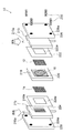
- FIG. 2 is an exploded perspective view of the solid alkaline fuel cell 10 manufactured in the present embodiment.
- the solid electrolyte body 16 was fitted into the circular opening (diameter 20 mm) of the electrolyte fixing jig 218 and fixed using a PTFE tape 220 having a circular opening 220 a with a diameter of 19 mm at the center.
- the cathode 12 and the anode 14 are printed on both sides of the inorganic solid electrolyte body 16, they are shown separately from the solid electrolyte body 16 in FIG. 2.
- a gasket 222 (made of PTFE) having an opening 222a formed on the cathode 12 side of the laminate of the anode 14 / inorganic solid electrolyte body 16 / cathode 12; an air supply member 213 for supplying humidified air (carbon And a collector plate 226 (made of gold-plated copper).
- the air supply member 213 includes a flow path 213 a for passing humidified air, and a slit (not shown) for supplying the humidified air to the cathode 12.
- a gasket 224 (made of PTFE) having an opening 224a formed on the anode 14 side of the laminate of the anode 14 / inorganic solid electrolyte body 16 / cathode 12; a fuel supply member 215 (made of carbon) for supplying fuel And a collector plate 228 (made of gold-plated copper).
- the fuel supply member 215 includes a flow path 215a for passing the fuel and a slit 215b for supplying the fuel to the fuel electrode.
- the solid alkaline fuel cell 10 was completed by fastening the above laminate with screws 230 inserted into screw holes 226a, 228a formed at the four corners of the two current collectors 226, 228.
- the infrared absorption spectrum of the cathode side surface 16S of the solid electrolyte body 16 is ATR (Attenuated Total) using an infrared spectrometer (JASCO FT / IR-6200 type-A). The absorption wavelength of 1820 to 1650 cm -1 obtained by the Reflection method and indicating the intensity of carbon dioxide gas was measured.
- the carbon dioxide concentration in the cathode side surface 16S was calculated by measuring the oxidizing agent collect
- the solid alkaline fuel cell 10 is disassembled to expose the cathode side surface 16S of the solid electrolyte body 16, and an infrared spectrometer is used The infrared absorption spectrum at the cathode side surface 16S was acquired, and the absorption wavelength of 1820 to 1650 cm -1 indicating the intensity of carbon dioxide gas was measured.
- the strength reduction rate of carbon dioxide gas before and after 720 hours of power generation was calculated.
- the case where the strength reduction rate of carbon dioxide gas was 10% or more was evaluated as x, and the case where the strength reduction rate of carbon dioxide gas was less than 10% was evaluated as ⁇ .
- dry air having a dew point of 0 ° C. or less was supplied to the air supply member 213 using a compressor, and the air utilization rate at the cathode 12 was adjusted to be 50%. Further, the vaporized methanol was supplied to the fuel supply member 215, and the fuel utilization rate at the anode 14 was adjusted to be 50%.
- the pressure of the fuel supplied to the anode 14 is the pressure of the air supplied to the cathode 12 using exhaust pressure control valves (not shown) attached to the exhaust paths of the air supply member 213 and the fuel supply member 215, respectively. I adjusted it to be bigger.
Landscapes
- Life Sciences & Earth Sciences (AREA)
- Engineering & Computer Science (AREA)
- Manufacturing & Machinery (AREA)
- Sustainable Development (AREA)
- Sustainable Energy (AREA)
- Chemical & Material Sciences (AREA)
- Chemical Kinetics & Catalysis (AREA)
- Electrochemistry (AREA)
- General Chemical & Material Sciences (AREA)
- Fuel Cell (AREA)
Abstract
固体アルカリ形燃料電池(10)は、カソード(12)と、アノード(14)と、LDHによって構成される無機固体電解質体(16)とを備える。固体アルカリ形燃料電池(10)を発電中、無機固体電解質体(16)のカソード側表面(16S)は、600ppm以上20000ppm以下の二酸化炭素含有雰囲気に曝される。
Description
本発明は、固体アルカリ形燃料電池の発電方法に関する。
比較的低温(例えば、250℃以下)で作動する燃料電池として、アルカリ形燃料電池(AFC)が知られている。AFCでは、様々な液体燃料又は気体燃料を使用することができ、例えばメタノールを燃料とした場合には、以下の電気化学反応が起こる。
・アノード: CH3OH+6OH-→6e-+CO2+5H2O
・カソード: 3/2O2+3H2O+6e-→6OH-
・全体 : CH3OH+3/2O2→CO2+2H2O
ここで、特許文献1には、水酸化物イオン伝導性を有する無機固体電解質体として、液透過性及び通気性を有さない層状複水酸化物(LDH:Layered Double Hydroxide)を用いた固体アルカリ形燃料電池が提案されている。
・カソード: 3/2O2+3H2O+6e-→6OH-
・全体 : CH3OH+3/2O2→CO2+2H2O
ここで、特許文献1には、水酸化物イオン伝導性を有する無機固体電解質体として、液透過性及び通気性を有さない層状複水酸化物(LDH:Layered Double Hydroxide)を用いた固体アルカリ形燃料電池が提案されている。
LDHは、一般式[M2+
1-xM3+
x(OH)2][An-
x/n・mH2O](M2+は2価の陽イオンであり、M3+は3価の陽イオンであり、An-はn価の陰イオンである。)によって表わされる。
LDHは、上記一般式の前半部分に相当する複水酸化物層の間に、上記一般式の後半部分に相当する陰イオン及び水が保持された積層構造を有する。複水酸化物層は、2価の金属水酸化物に3価の金属イオンが固溶することによって構成されており、正電荷を有している。層間の陰イオンは、複水酸化物層の正電荷を補償するように負電荷を有している。
ところで、LDHの水酸化物イオン伝導性を改善させることによって、固体アルカリ形燃料電池の発電能力を向上させたいという要望がある。
本発明者等が検討した結果、LDHのカソード側表面を所定濃度の二酸化炭素含有雰囲気に曝すことによって、LDHの層間に配位されている陰イオンの安定性が向上し、その結果、水酸化物イオン伝導性が改善するという新たな知見を得た。
本発明は、上述の新たな知見に基づいてなされたものであり、発電能力を向上可能な固体アルカリ形燃料電池の発電方法を提供することを目的とする。
本発明に係る固体アルカリ形燃料電池の発電方法は、カソードと、アノードと、前記カソードと前記アノードとの間に配置され、水酸化物イオン伝導性を有する層状複水酸化物によって構成される無機固体電解質体とを備える固体アルカリ形燃料電池の発電方法であって、前記無機固体電解質体のカソード側表面を、600ppm以上20000ppm以下の二酸化炭素含有雰囲気に曝すことを特徴とする。
本発明によれば、発電能力を向上可能な固体アルカリ形燃料電池の発電方法を提供することができる。
(固体アルカリ形燃料電池10)
固体アルカリ形燃料電池10は、比較的低温で作動するアルカリ形燃料電池(AFC)の一種である。本実施形態に係る固体アルカリ形燃料電池10の作動温度は、50℃~250℃である。固体アルカリ形燃料電池10は、例えばメタノールによって作動し、以下のような電気化学反応によって発電する。
固体アルカリ形燃料電池10は、比較的低温で作動するアルカリ形燃料電池(AFC)の一種である。本実施形態に係る固体アルカリ形燃料電池10の作動温度は、50℃~250℃である。固体アルカリ形燃料電池10は、例えばメタノールによって作動し、以下のような電気化学反応によって発電する。
・カソード12: 3/2O2+3H2O+6e-→6OH-
・アノード14: CH3OH+6OH-→6e-+CO2+5H2O
・全体 : CH3OH+3/2O2→CO2+2H2O
・アノード14: CH3OH+6OH-→6e-+CO2+5H2O
・全体 : CH3OH+3/2O2→CO2+2H2O
図1は、固体アルカリ形燃料電池10の構成を模式的に示す断面図である。固体アルカリ形燃料電池10は、カソード12、アノード14、及び無機固体電解質体16を備える。
カソード12は、一般的に空気極と呼ばれる陽極である。固体アルカリ形燃料電池10の発電中、カソード12には、酸化剤供給手段13を介して、酸素(O2)を含む酸化剤が供給される。酸化剤としては、空気を用いることができる。また、酸化剤には、必要に応じて水(H2O)を含ませることが好ましい。酸化剤としては、例えば、空気、加湿空気などを用いることができる。
なお、本明細書において、「水(H2O)」は、気体状態の水蒸気、液体状態の水分、及び、水蒸気と水分との気液混合物のいずれであってもよい。
カソード12は、アルカリ形燃料電池に使用される公知のカソード触媒を含むものであればよく、特に限定されない。カソード触媒の例としては、白金族元素(Ru、Rh、Pd、Os、Ir、Pt)、鉄族元素(Fe、Co、Ni)等の第8~10族元素(IUPAC形式での周期表において第8~10族に属する元素)、Cu、Ag、Au等の第11族元素(IUPAC形式での周期表において第11族に属する元素)、ロジウムフタロシアニン、テトラフェニルポルフィリン、Coサレン、Niサレン(サレン=N,N’-ビス(サリチリデン)エチレンジアミン)、銀硝酸塩、及びこれらの任意の組み合わせが挙げられる。カソード12における触媒の担持量は特に限定されないが、好ましくは0.1~10mg/cm2、より好ましくは、0.1~5mg/cm2である。カソード触媒はカーボンに担持させるのが好ましい。カソード12ないしそれを構成する触媒の好ましい例としては、白金担持カーボン(Pt/C)、パラジウム担持カーボン(Pd/C)、ロジウム担持カーボン(Rh/C)、ニッケル担持カーボン(Ni/C)、銅担持カーボン(Cu/C)、及び銀担持カーボン(Ag/C)が挙げられる。
カソード12の作製方法は特に限定されないが、例えば、カソード触媒及び所望により担体をバインダーと混合してペースト状にし、このペースト状混合物を無機固体電解質体16の一方の面に塗布することにより形成すればよい。
アノード14は、一般的に燃料極と呼ばれる陰極である。固体アルカリ形燃料電池10の発電中、アノード14には、燃料供給手段15を介して燃料が供給される。燃料は、液体燃料及び気体燃料のいずれの形態であってもよい。液体燃料は、燃料化合物そのものが液体であってもよいし、固体の燃料化合物を水やアルコール等の液体に溶解させたものであってもよい。
燃料化合物としては、例えば、(i)ヒドラジン(NH2NH2)、水加ヒドラジン(NH2NH2・H2O)、炭酸ヒドラジン((NH2NH2)2CO2)、硫酸ヒドラジン(NH2NH2・H2SO4)、モノメチルヒドラジン(CH3NHNH2)、ジメチルヒドラジン((CH3)2NNH2、CH3NHNHCH3)、及びカルボンヒドラジド((NHNH2)2CO)等のヒドラジン類、(ii)尿素(NH2CONH2)、(iii)アンモニア(NH3)、(iv)イミダゾール、1,3,5-トリアジン、3-アミノ-1,2,4-トリアゾール等の複素環類化合物、(v)ヒドロキシルアミン(NH2OH)、硫酸ヒドロキシルアミン(NH2OH・H2SO4)等のヒドロキシルアミン類、及びこれらの組合せが挙げられる。
上記燃料化合物のうち炭素を含まない化合物(すなわち、ヒドラジン、水加ヒドラジン、硫酸ヒドラジン、アンモニア、ヒドロキシルアミン、硫酸ヒドロキシルアミン等)は、一酸化炭素による触媒被毒の問題が無いため耐久性の向上を図ることができるだけでなく、二酸化炭素の排出を無くすこともできる。
上記燃料化合物は、そのまま燃料として用いてもよいが、水及び/又はアルコール(例えば、メタノール、エタノール、プロパノール、イソプロパノールなどの低級アルコール等)に溶解させた溶液として用いてもよい。例えば、上記燃料化合物のうち、ヒドラジン、水化ヒドラジン、モノメチルヒドラジン及びジメチルヒドラジンは液体であるので、そのまま液体燃料として使用可能である。また、炭酸ヒドラジン、硫酸ヒドラジン、カルボンヒドラジド、尿素、イミダゾール、及び3-アミノ-1,2,4-トリアゾール、及び硫酸ヒドロキシルアミンは固体であるが水に可溶である。1,3,5-トリアジン及びヒドロキシルアミンは固体であるがアルコールに可溶である。アンモニアは気体であるが水に可溶である。このように、固体の燃料化合物は、水又はアルコールに溶解させて液体燃料として使用可能である。燃料化合物を水及び/又はアルコールに溶解させて用いる場合、溶液中の燃料化合物の濃度は、例えば1~90重量%であり、好ましくは1~30重量%である。
さらに、メタノール、エタノール等のアルコール類やエーテル類を含む炭化水素系液体燃料、メタン等の炭化水素系ガス、或いは純水素などは、そのまま燃料として用いることができる。特に、本実施形態に係る固体アルカリ形燃料電池10に用いられる燃料としては、メタノールが好適である。メタノールは、気体状態、液体状態、及び、気液混合状態のいずれであってもよい。
アノード14は、アルカリ形燃料電池に使用される公知のアノード触媒を含むものであればよく、特に限定されない。アノード触媒の例としては、Pt、Ni、Co、Fe、Ru、Sn、及びPd等の金属触媒が挙げられる。金属触媒は、カーボン等の担体に担持されるのが好ましいが、金属触媒の金属原子を中心金属とする有機金属錯体の形態としてもよく、このような有機金属錯体を担体として担持されていてもよい。また、アノード触媒の表面には多孔質材料等で構成された拡散層を配置してもよい。アノード14ないしそれを構成する触媒の好ましい例としては、ニッケル、コバルト、銀、白金担持カーボン(Pt/C)、パラジウム担持カーボン(Pd/C)、ロジウム担持カーボン(Rh/C)、ニッケル担持カーボン(Ni/C)、銅担持カーボン(Cu/C)、及び銀担持カーボン(Ag/C)が挙げられる。
アノード14の作製方法は特に限定されないが、例えば、アノード触媒及び所望により担体をバインダーと混合してペースト状にし、このペースト状混合物を無機固体電解質体16のカソード12と反対側の面に塗布することにより形成すればよい。
無機固体電解質体16は、カソード12とアノード14との間に配置される。無機固体電解質体16は、カソード側表面16Sとアノード側表面16Tとを有する。カソード側表面16Sは、無機固体電解質体16の外表面のうちカソード12が配置される空間に露出する領域であり、カソード12と対向する。アノード側表面16Tは、無機固体電解質体16の外表面のうちアノード14が配置される空間に露出する領域であり、アノード14と対向する。
無機固体電解質体16は、水酸化物イオン伝導性を有する層状複水酸化物(Layered Double Hydroxide、以下「LDH」という。)によって構成される。無機固体電解質体16は、AEM(アニオン交換膜)のような有機系材料を電解質として用いる場合に比べて優れた耐熱性及び耐久性を発揮する。無機固体電解質体16の水酸化物イオン伝導度は、高ければ高いほど好ましいが、典型的には10-4~10-1S/mである。
LDHは、一般式:[M2+
1-xM3+
x(OH)2][An-
x/n・mH2O](式中、M2+は2価の陽イオンであり、M3+は3価の陽イオンであり、An-はn価の陰イオンであり、nは1以上の整数であり、xは0.1~0.4である)によって表される基本組成を有する。
LDHは、上記一般式の前半部分に相当する複水酸化物層の間に、上記一般式の後半部分に相当する陰イオンと水が保持された積層構造を有する。複水酸化物層は、2価の金属水酸化物に3価の金属イオンが固溶することによって構成されており、正電荷を有している。層間の陰イオンは、複水酸化物層の正電荷を補償するように負電荷を有している。
上記一般式において、M2+は、任意の2価の陽イオンでありうるが、好ましい例としてはMg2+、Ca2+及びZn2+が挙げられ、より好ましくはMg2+である。M3+は、任意の3価の陽イオンでありうるが、好ましい例としてはAl3+又はCr3+が挙げられ、より好ましくはAl3+である。An-は、任意の陰イオンでありうるが、好ましい例としてはOH-及びCO3
2-が挙げられる。
従って、上記一般式において、M2+がMg2+を含み、M3+がAl3+を含み、An-がOH-及び/又はCO3
2-を含むのが特に好ましい。nは、1以上の整数であるが、好ましくは1又は2である。xは、0.1~0.4であるが、好ましくは0.2~0.35である。mは、任意の実数である。
また、上記一般式においてM3+の一部または全部を4価以上の価数の陽イオンで置き換えてもよく、その場合は、上記一般式における陰イオンAn-の係数x/nは適宜変更されてよい。
ここで、本実施形態に係る無機固体電解質体16のカソード側表面16Sは、固体アルカリ形燃料電池10の発電中、600ppm以上20000ppm以下の二酸化炭素含有雰囲気に曝される。このように、カソード側表面16Sを上記濃度範囲の二酸化炭素含有雰囲気に曝した状態で運転(発電)することによって、LDHの層間に配位されている陰イオンの安定性を向上させることができる。その結果、無機固体電解質体16の水酸化物イオン伝導性が改善されるため、固体アルカリ形燃料電池10の発電能力を向上させることができる。
カソード側表面16Sを上記濃度範囲の二酸化炭素含有雰囲気に曝すには、例えば、下記の第1手法、第2手法、第3手法、又は、第1乃至第3手法の組み合わせのいずれかを採用することができる。
第1手法は、酸化剤供給手段13を介してカソード12に供給される酸化剤に二酸化炭素を含有させる手法である。この場合、酸化剤は、酸素と水と上記濃度範囲の二酸化炭素とを含有することになる。酸化剤として加湿空気を用いる場合には、空気に含まれている二酸化炭素の濃度を考慮して、加湿空気に所望濃度の二酸化炭素を添加すればよい。
第2手法は、無機固体電解質体16に貫通孔を設ける手法である。貫通孔は、アノード側表面16Tからカソード側表面16Sまで無機固体電解質体16の内部を貫通するように形成されていればよく、形状は限定されない。この貫通孔は、アノード14に供給される燃料と、アノード14における電気化学反応によって生成される二酸化炭素とをカソード12に透過させる。貫通孔を介してカソード12に透過した燃料が酸化剤に含まれる酸素と反応すると、二酸化炭素が生成される。例えば、燃料としてメタノールを用いる場合には、カソード12において以下の反応が起こる。
・カソード12: CH3OH+3/2O2→CO2+2H2O
このように、第2手法では、貫通孔を介してカソード12に透過した燃料から生成される二酸化炭素と、アノード14における電気化学反応によって生成された二酸化炭素とを利用するものである。貫通孔の内径及び本数は、無機固体電解質体16のカソード側表面16S付近の二酸化炭素濃度が上記濃度範囲になるように適宜設定すればよい。酸化剤として加湿空気を用いる場合には、空気に含まれている二酸化炭素の濃度を考慮して、貫通孔の内径及び本数を設定すればよい。貫通孔は、無機固体電解質体16のうち酸化剤供給手段13の供給口近くに配置されることが好ましい。これによって、貫通孔からカソード12に流出した燃料が酸素と反応することで生成される二酸化炭素を、酸化剤とともにカソード12全体に行き渡らせることができる。
第3手法は、無機固体電解質体16に気孔を設ける手法である。気孔は、アノード側表面16Tからカソード側表面16Sまで無機固体電解質体16の内部を連なるように形成されることが好ましい。この気孔は、アノード14に供給される燃料と、アノード14における電気化学反応によって生成される二酸化炭素とをカソード12に透過させる。この第3手法は、上述した第2手法と同様、気孔を介してカソード12に透過した燃料から生成される二酸化炭素と、アノード14における電気化学反応によって生成された二酸化炭素とを利用するものである。気孔の形状は特に制限されるものではなく、不定形状、或いは網の目状などであってもよい。気孔は、無機固体電解質体16の全体に広く形成されていてもよいし、無機固体電解質体16の一部のみに形成されていてもよい。気孔の内径、長さ、及び本数は、無機固体電解質体16のカソード側表面16S付近の二酸化炭素濃度が上記濃度範囲になるように適宜設定すればよい。酸化剤として加湿空気を用いる場合には、空気に含まれている二酸化炭素の濃度を考慮して、気孔の内径及び本数を設定すればよい。
なお、無機固体電解質体16のカソード側表面16Sを上記濃度範囲の二酸化炭素含有雰囲気に曝せば、必然的にカソード14も二酸化炭素含有雰囲気に曝されることになるが、二酸化炭素は不活性ガスであるため、カソード14の触媒活性にはほとんど影響を与えない。
無機固体電解質体16は、LDHを含む粒子群のみによって構成されていてもよいが、この粒子群の緻密化や硬化を助ける補助成分を含んでいてもよい。
また、無機固体電解質体16は、基材としての開気孔性の多孔質体と、この多孔質体の孔を埋めるように孔中に析出及び成長させたLDHとの複合体であってもよい。多孔質体は、アルミナ及びジルコニアなどのセラミックス材料や、発泡樹脂又は繊維状物質からなる多孔性シート等の絶縁性材料によって構成することができる。
無機固体電解質体16は、板状、膜状及び層状のいずれの形態であってもよい。無機固体電解質体16が膜状又は層状である場合、無機固体電解質体16は、膜状又は層状に形成されたLDHが多孔質基材上又は多孔質基材中に形成されたものであってもよい。無機固体電解質体16が膜状又は層状である場合、無機固体電解質体16の厚さは、100μm以下とすることができ、好ましくは75μm以下、より好ましくは50μm以下、さらに好ましくは25μm以下、特に好ましくは5μm以下である。無機固体電解質体16を薄くすることによって、無機固体電解質体16の抵抗を低減できる。無機固体電解質体16の厚さの下限値は、用途に応じて設定可能であるが、ある程度の堅さを確保するには1μm以上が好ましく、2μm以上がより好ましい。無機固体電解質体16が板状である場合、無機固体電解質体16の厚さは、0.01mm~0.5mmとすることができ、好ましくは0.02mm~0.2mmであり、より好ましくは0.05mm~0.1mmである。
(無機固体電解質体16の製造方法)
無機固体電解質体16の製造方法の一例について説明する。以下に説明する製造方法は、ハイドロタルサイトに代表されるLDHの粉末を成形及び焼成して酸化物焼成体とし、これをLDHへ再生した後、余剰の水分を除去することにより行われる。この製造方法によれば、緻密な無機固体電解質体16を簡便かつ安定的に製造できる。
無機固体電解質体16の製造方法の一例について説明する。以下に説明する製造方法は、ハイドロタルサイトに代表されるLDHの粉末を成形及び焼成して酸化物焼成体とし、これをLDHへ再生した後、余剰の水分を除去することにより行われる。この製造方法によれば、緻密な無機固体電解質体16を簡便かつ安定的に製造できる。
1.LDH粉末の準備
上述した一般式:[M2+ 1-xM3+ x(OH)2][An- x/n・mH2O](式中、M2+は2価の陽イオン、M3+は3価の陽イオンであり、An-はn価の陰イオン、nは1以上の整数、xは0.1~0.4である)によって表される基本組成を有するLDH粉末を準備する。このようなLDH粉末は市販品であってもよいし、硝酸塩や塩化物を用いた液相合成法等の公知の方法にて作製した原料であってもよい。
上述した一般式:[M2+ 1-xM3+ x(OH)2][An- x/n・mH2O](式中、M2+は2価の陽イオン、M3+は3価の陽イオンであり、An-はn価の陰イオン、nは1以上の整数、xは0.1~0.4である)によって表される基本組成を有するLDH粉末を準備する。このようなLDH粉末は市販品であってもよいし、硝酸塩や塩化物を用いた液相合成法等の公知の方法にて作製した原料であってもよい。
LDH粉末の粒径は特に限定されないが、体積基準D50平均粒径は、0.1μm~1.0μmが好ましく、0.3μm~0.8μmがより好ましい。LDH粉末の粒径が細かすぎると粉末が凝集して成形時に気孔が残留しやすく、LDH粉末の粒径が大きすぎると成形性が悪くなりやすい。
LDH粉末は、仮焼によって酸化物粉末としてもよい。この際の仮焼温度は、原料粒径が大きく変化しない温度範囲に設定することができ、例えば500℃以下が好ましく、380℃~460℃がより好ましい。
2.成形体の作製工程
次に、LDH粉末を成形して成形体を得る。この成形は、成形体の相対密度が43%~65%、より好ましくは45%~60%、さらに好ましくは47%~58%になるように、例えば加圧成形により行われるのが好ましい。加圧成形には、金型一軸プレス、冷間等方圧加圧(CIP)、スリップキャスト、或いは押出成形など公知の手法を用いることができる。ただし、LDH粉末を仮焼して酸化物粉末とした場合は、乾式成形法に限られる。
次に、LDH粉末を成形して成形体を得る。この成形は、成形体の相対密度が43%~65%、より好ましくは45%~60%、さらに好ましくは47%~58%になるように、例えば加圧成形により行われるのが好ましい。加圧成形には、金型一軸プレス、冷間等方圧加圧(CIP)、スリップキャスト、或いは押出成形など公知の手法を用いることができる。ただし、LDH粉末を仮焼して酸化物粉末とした場合は、乾式成形法に限られる。
上述した第3手法(気孔を設ける手法)によってカソード側表面16Sを上記濃度範囲の二酸化炭素含有雰囲気に曝す場合には、LDH粉末に造孔材(例えば、メチルセルロース、アクリル系ポリマーなど)を添加して成形体を形成する。この造孔材が後述する焼成工程で焼成除去されることによって、酸化物焼成体の内部に気孔が形成される。気孔の内径、長さ及び本数は、造孔材の粒径及び量によって調整可能である。
成形体の相対密度は、成形体の寸法及び重量から密度を算出し、理論密度で除して求められる。成形体の重量は吸着水分の影響を受けるため、一義的な値を得るために、室温、相対湿度20%以下のデシケータ内で24時間以上保管したLDH粉末を用いた成形体か、もしくは成形体を前記条件下で保管した後に相対密度を測定するのが好ましい。
ただし、LDH粉末を仮焼して酸化物粉末とした場合には、成形体の相対密度が26%~40%、より好ましくは29~36%にする。酸化物粉末を用いる場合の相対密度は、LDHを構成する各金属元素が仮焼により各々酸化物に変化したと仮定して、各酸化物の混合物として求めた換算密度を分母として求める。
3.焼成工程
次に、成形体を焼成して酸化物焼成体を得る。この焼成は、酸化物焼成体が、成形体の重量の57%~65%の重量、及び/又は、成形体の体積の70%~76%の体積となるように行われるのが好ましい。
次に、成形体を焼成して酸化物焼成体を得る。この焼成は、酸化物焼成体が、成形体の重量の57%~65%の重量、及び/又は、成形体の体積の70%~76%の体積となるように行われるのが好ましい。
酸化物焼成体の重量を、成形体の重量の57%以上とすることで、後工程のLDHへの再生時に再生できない異相が生成されにくくなり、成形体の重量の65%以下とすることで、焼成が十分に行われて後工程で十分に緻密化する。また、酸化物焼成体の体積を、成形体の体積の70%以上とすることで、後工程のLDHへの再生時に異相が生成にくくなるとともに、クラックも生じにくくなり、成形体の体積の76%以下とすることで、焼成が十分に行われて後工程で十分に緻密化する。
ただし、LDH粉末を仮焼して酸化物粉末とした場合は、酸化物焼成体が、成形体の重量の85%~95%、及び/又は、成形体の体積の90%以上の体積となるように焼成されるのが好ましい。
また、LDH粉末を仮焼したか否かに関わらず、焼成は、酸化物焼成体の相対密度が、酸化物換算で20%~40%になるように行われるのが好ましく、より好ましくは20%~35%であり、さらに好ましくは20%~30%である。酸化物換算での相対密度とは、LDHを構成する各金属元素が焼成により各々酸化物に変化したと仮定し、各酸化物の混合物として求めた換算密度を分母として求めた相対密度である。
成形体の焼成温度は400℃~850℃とすることができ、700℃~800℃が好ましい。焼成工程は、1時間以上、好ましくは3時間~10時間の間、上記焼成温度で保持する工程を含むのが好ましい。また、急激な昇温により水分や二酸化炭素が放出して成形体が割れるのを防ぐため、上記焼成温度に到達するまでの昇温速度は100℃/h以下が好ましく、5℃/h~75℃/hがより好ましく、10℃/h~50℃/hがさらに好ましい。従って、昇温から降温(100℃以下)に至るまでの全焼成時間は、20時間以上が好ましく、30時間~70時間がより好ましく、35時間~65時間がさらに好ましい。
なお、上述した成形体の作製工程において成形体に造孔材を添加した場合には、この焼成工程において造孔材が焼成除去されることによって、酸化物焼成体の内部に気孔が形成される。
4.LDHへの再生工程
次に、酸化物焼成体を上述したn価の陰イオン(An-)を含む水溶液中又はその直上に保持してLDHへと再生し、それにより水分に富むLDH固化体を得る。すなわち、この製法により得られるLDH固化体は必然的に余分な水分を含んでいる。
次に、酸化物焼成体を上述したn価の陰イオン(An-)を含む水溶液中又はその直上に保持してLDHへと再生し、それにより水分に富むLDH固化体を得る。すなわち、この製法により得られるLDH固化体は必然的に余分な水分を含んでいる。
なお、水溶液中に含まれる陰イオンはLDH粉末中に含まれる陰イオンと同種の陰イオンとしてよいし、異なる種類の陰イオンとしてもよい。
酸化物焼成体の水溶液中又は水溶液直上での保持は、密閉容器内で水熱合成の手法により行われるのが好ましい。密閉容器の例としては、テフロン(登録商標)製の密閉容器が挙げられる。密閉容器の外側には、ステンレス製等のジャケットを設けることが好ましい。
LDH化は、酸化物焼成体を20℃以上200℃未満で、少なくとも酸化物焼成体の一面が水溶液に接する状態に保持することにより行われるのが好ましく、より好ましい温度は50℃~180℃であり、さらに好ましい温度は100℃~150℃である。このようなLDH化温度で、酸化物焼結体は1時間以上保持されるのが好ましく、2時間以上保持されるのがより好ましく、5時間以上保持されるのがさらに好ましい。これによって、十分にLDHへの再生を進行させて異相が残るのを抑制できる。なお、保持時間は、長すぎても特に問題はないが、効率性を重視して適宜設定すればよい。
LDHへの再生に使用するn価の陰イオンを含む水溶液の陰イオン種として空気中の二酸化炭素(炭酸イオン)を利用する場合、イオン交換水を用いることができる。なお、密閉容器内の水熱処理の際には、酸化物焼成体を水溶液中に水没させてもよいし、治具を用いて少なくとも一面が水溶液に接する状態で処理を行ってもよい。少なくとも一面が水溶液に接する状態で処理した場合、完全水没と比較して余分な水分量が少ないので、その後の工程が短時間で済む場合がある。ただし、水溶液が少なすぎるとクラックが発生しやすくなるため、焼成体重量と同等以上の水分を用いるのが好ましい。
なお、酸化物焼成体の内部に気孔が形成されている場合、この再生工程後であっても、LDH固化体の内部には気孔が残される。
5.脱水工程
次に、LDH固化体から余剰水分を除去することによって、無機固体電解質体16を得る。余剰水分を除去する工程は、300℃以下、除去工程の最高温度での推定相対湿度25%以上の環境下で行われるのが好ましい。LDH固化体からの急激な水分の蒸発を防ぐため、室温より高い温度で脱水する場合はLDHへの再生工程で使用した密閉容器中に再び封入して行うことが好ましい。その場合の好ましい温度は50℃~250℃であり、さらに好ましくは100℃~200℃である。また、脱水時のより好ましい相対湿度は25%~70%であり、さらに好ましくは40%~60%である。脱水を室温で行ってもよく、その場合の相対湿度は通常の室内環境における40%~70%の範囲内であればよい。
次に、LDH固化体から余剰水分を除去することによって、無機固体電解質体16を得る。余剰水分を除去する工程は、300℃以下、除去工程の最高温度での推定相対湿度25%以上の環境下で行われるのが好ましい。LDH固化体からの急激な水分の蒸発を防ぐため、室温より高い温度で脱水する場合はLDHへの再生工程で使用した密閉容器中に再び封入して行うことが好ましい。その場合の好ましい温度は50℃~250℃であり、さらに好ましくは100℃~200℃である。また、脱水時のより好ましい相対湿度は25%~70%であり、さらに好ましくは40%~60%である。脱水を室温で行ってもよく、その場合の相対湿度は通常の室内環境における40%~70%の範囲内であればよい。
上述した第2手法(貫通孔を設ける手法)によってカソード側表面16Sを上記濃度範囲の二酸化炭素含有雰囲気に曝す場合には、余剰水分が除去された後の無機固体電解質体16に貫通孔を直接形成する。貫通孔は、レーザー加工や放電加工を用いて無機固体電解質体16の厚み方向に孔をあけることで形成することができる。貫通孔の内径は、例えばレーザー加工の場合では照射するレーザーの径や照射パターンを制御することによって調整可能である。
以下において本発明の実施例について説明する。ただし、本発明は以下に説明する実施例には限定されない。
(固体アルカリ形燃料電池10の作製)
(1)無機固体電解質体16の作製
まず、原料粉末として、市販の層状複水酸化物であるハイドロタルサイト粉末(DHT-4H、協和化学工業株式会社製)を用意した。この原料粉末の組成はMg2+ 0.68Al3+ 0.32(OH)2CO3 2- 0.16・mH2Oであった。直径20mmの円板状の金型に原料粉末を充填して、500kgf/cm2の成形圧で一軸プレス成形することによって、相対密度53%、直径20mm、厚さ約0.8mmの成形体を得た。なお、この相対密度の測定は、室温、相対湿度20%以下で24時間保管した成形体について行った。
(1)無機固体電解質体16の作製
まず、原料粉末として、市販の層状複水酸化物であるハイドロタルサイト粉末(DHT-4H、協和化学工業株式会社製)を用意した。この原料粉末の組成はMg2+ 0.68Al3+ 0.32(OH)2CO3 2- 0.16・mH2Oであった。直径20mmの円板状の金型に原料粉末を充填して、500kgf/cm2の成形圧で一軸プレス成形することによって、相対密度53%、直径20mm、厚さ約0.8mmの成形体を得た。なお、この相対密度の測定は、室温、相対湿度20%以下で24時間保管した成形体について行った。
次に、得られた成形体をアルミナ鞘中で焼成した。この焼成は、急激な昇温により水分や二酸化炭素が放出して成形体が割れるのを防ぐため、100℃/h以下の速度で昇温を行い、750℃の最高温度に達した時点で5時間保持した後、冷却することにより行った。この昇温から降温(100℃以下)に至るまでの全焼成時間は62時間であった。
次に、外側にステンレス製ジャケットを備えたテフロン(登録商標)製の密閉容器に焼成体を入れ、大気中でイオン交換水と共に封入した。そして、100℃で5時間保持する再生条件で焼成体に水熱処理を施した後、厚みが0.3mmになるよう研磨し、ろ紙で焼成体表面の水分を拭き取った。こうして得られた焼成体を25℃、相対湿度が50%程度の室内で自然脱水(乾燥)することによって、無機固体電解質体16を形成した。
次に、実施例1~3及び比較例2,3では、レーザーを用いて、無機固体電解質体16を厚み方向に貫通する貫通孔を形成した。この際、レーザー出力及び照射時間の制御により貫通孔の内径を調整することによって、後述する初期出力測定において無機固体電解質体16を透過する燃料量及び二酸化炭素量を調整した。
(2)カソード12及びアノード14の作製
Pt担持量50wt%(田中貴金属工業(株)社製TEC10E50E)の白金担持カーボン(以下、「Pt/C」という。)と、バインダーであるPVDF粉末(以下、「PVDFバインダー」という。)とを準備した。そして、(Pt/C触媒):(PVDFバインダー):(水)の重量比が9wt%:0.9wt%:90wt%の比率となるように、Pt/C、PVDFバインダー及び水を混合してペースト化することによってカソード用ペーストを作製した。
Pt担持量50wt%(田中貴金属工業(株)社製TEC10E50E)の白金担持カーボン(以下、「Pt/C」という。)と、バインダーであるPVDF粉末(以下、「PVDFバインダー」という。)とを準備した。そして、(Pt/C触媒):(PVDFバインダー):(水)の重量比が9wt%:0.9wt%:90wt%の比率となるように、Pt/C、PVDFバインダー及び水を混合してペースト化することによってカソード用ペーストを作製した。
また、Pt-Ru担持量54wt%(田中貴金属工業(株)社製TEC61E54)の白金ルテニウム担持カーボン(以下、「Pt-Ru/C」という。)と、PVDFバインダーとを準備した。そして、(Pt-Ru/C触媒):(PVDFバインダー):(水)の重量比が9wt%:0.9wt%:90wt%の比率となるように、Pt-Ru/C、PVDFバインダー及び水を混合してペースト化することによってアノード用ペーストを作製した。
次に、カソード用ペーストを無機固体電解質体16の一方の面に印刷し、アノード用ペーストを無機固体電解質体16の他方の面に印刷した後、N2雰囲気中において180℃で4時間熱処理することによって、カソード12/無機固体電解質体16/アノード14の接合体を得た。
(3)固体アルカリ形燃料電池10の組み立て
図2は、本実施例で作製した固体アルカリ形燃料電池10の分解斜視図である。
図2は、本実施例で作製した固体アルカリ形燃料電池10の分解斜視図である。
まず、固体電解質体16を、電解質固定用治具218の円形の開口部(直径20mm)に嵌め、中央に直径19mmの円形の開口部220aが形成されたPTFEテープ220を用いて固定した。なお、カソード12及びアノード14は、無機固体電解質体16の両面に印刷されているが、図2では固体電解質体16から分離して表示されている。
次に、アノード14/無機固体電解質体16/カソード12の積層物のカソード12側に、開口部222aが形成されたガスケット222(PTFE製)、加湿空気を供給するための空気供給部材213(カーボン製)及び集電板226(金メッキした銅製)を積層した。空気供給部材213は、加湿空気を通すための流路213aと、加湿空気をカソード12に供給するためのスリット(不図示)とを備える。
次に、アノード14/無機固体電解質体16/カソード12の積層物のアノード14側に、開口部224aが形成されたガスケット224(PTFE製)、燃料を供給するための燃料供給部材215(カーボン製)及び集電板228(金メッキした銅製)を積層した。燃料供給部材215は、燃料を通すための流路215aと、燃料を燃料極に供給するためのスリット215bとを備える。
以上の積層物を、2枚の集電板226,228の四隅に形成されたネジ穴226a,228aに挿入したネジ230で締結することによって、固体アルカリ形燃料電池10を完成させた。
(固体電解質体16の耐久試験)
まず、固体アルカリ形燃料電池10を組み立てる前に、赤外分光装置(日本分光 FT/IR-6200 type-A)を用いて固体電解質体16のカソード側表面16Sにおける赤外線吸収スペクトルをATR(Attenuated Total Reflection)法にて取得し、炭酸ガスの強度を示す1820~1650cm-1の吸収波長を測定した。
まず、固体アルカリ形燃料電池10を組み立てる前に、赤外分光装置(日本分光 FT/IR-6200 type-A)を用いて固体電解質体16のカソード側表面16Sにおける赤外線吸収スペクトルをATR(Attenuated Total Reflection)法にて取得し、炭酸ガスの強度を示す1820~1650cm-1の吸収波長を測定した。
次に、固体アルカリ形燃料電池10を120℃に加熱した。
次に、水素を燃料供給部材215に供給し、アノード14における燃料利用率が50%となるように調整した。また、コンプレッサーを用いて、露点0℃以下の乾燥空気と二酸化炭素との混合気体を空気供給部材213に供給し、カソード12における空気利用率が50%となるように調整した。この際、二酸化炭素の混合量を調整することによって、無機固体電解質体16のカソード側表面16Sにおける二酸化炭素濃度を表1に示すとおりサンプルごとに変更した。
なお、カソード側表面16Sにおける二酸化炭素濃度は、カソード12を通過した後に全量回収される酸化剤をガスクロマトグラフ装置で測定することによって算出した。
次に、定格負荷(0.3A/cm2)で720時間発電させた後、固体アルカリ形燃料電池10を分解して固体電解質体16のカソード側表面16Sを露出させ、赤外分光装置を用いてカソード側表面16Sにおける赤外線吸収スペクトルを取得し、炭酸ガスの強度を示す1820~1650cm-1の吸収波長を測定した。
そして、720時間の発電前後における炭酸ガスの強度低下率(発電前炭酸ガス強度-発電後炭酸ガス強度/発電前炭酸ガス強度)を算出した。表1では、炭酸ガスの強度低下率が10%以上の場合を×と評価し、炭酸ガスの強度低下率が10%未満の場合を○と評価した。
(固体アルカリ形燃料電池10の初期出力測定)
まず、固体アルカリ形燃料電池10を120℃に加熱した。
まず、固体アルカリ形燃料電池10を120℃に加熱した。
次に、コンプレッサーを用いて、露点0℃以下の乾燥空気を空気供給部材213に供給し、カソード12における空気利用率が50%となるように調整した。また、気化させたメタノールを燃料供給部材215に供給し、アノード14における燃料利用率が50%となるように調整した。そして、空気供給部材213及び燃料供給部材215それぞれの排出路に取り付けた排圧調整弁(不図示)を用いて、アノード14に供給される燃料の圧力が、カソード12に供給される空気の圧力より大きくなるよう調整した。
次に、定格負荷(0.3A/cm2)で発電させたときの固体アルカリ形燃料電池10の初期出力を測定した。そして、無機固体電解質体16に貫通孔を設けていない比較例1に係る固体アルカリ形燃料電池10の出力を100%として各サンプルの初期出力を規格化し、比較例1を基準とする出力低減率を算出した。表1では、出力低減率が10%以上の場合を×と評価し、出力低減率が10%未満の場合を○と評価した。

表1に示すように、無機固体電解質体16に貫通孔を形成しなかった比較例1と、カソード側表面16Sを500ppmの二酸化炭素含有雰囲気に曝した比較例2では、固体電解質体16の耐久試験における炭酸ガスの強度低下率が大きかった。このような結果が得られたのは、カソード側表面16Sを十分に高い濃度の二酸化炭素含有雰囲気に曝すことができず、LDHの層間に配位されたCO3
2-の安定性を向上させられなかったためと考えられる。また、カソード側表面16Sを3000ppmの二酸化炭素含有雰囲気に曝した比較例3では、固体アルカリ形燃料電池10の初期出力が低かった。このような結果が得られたのは、無機固体電解質体16に対して貫通孔が占める割合が大きかったため、無機固体電解質体16自体の特性が低下したためと考えられる。
一方、カソード側表面16Sを600ppm以上20000ppm以下の二酸化炭素含有雰囲気に曝した実施例1~3では、固体電解質体16の耐久試験における炭酸ガスの強度低下率を抑制でき、かつ、固体アルカリ形燃料電池10の初期出力も維持できた。このような結果が得られたのは、カソード側表面16Sを十分に高い濃度の二酸化炭素含有雰囲気に曝すことによってLDHの層間に配位されたCO3
2-の安定性を向上でき、かつ、無機固体電解質体16自体の特性も維持できたためと考えられる。
10 固体アルカリ形燃料電池
12 カソード
14 アノード
16 無機固体電解質体
16S カソード側表面
16T アノード側表面
12 カソード
14 アノード
16 無機固体電解質体
16S カソード側表面
16T アノード側表面
Claims (1)
- カソードと、アノードと、前記カソードと前記アノードとの間に配置され、水酸化物イオン伝導性を有する層状複水酸化物によって構成される無機固体電解質体とを備える固体アルカリ形燃料電池の発電方法であって、
前記無機固体電解質体のカソード側表面を、600ppm以上20000ppm以下の二酸化炭素含有雰囲気に曝す、
固体アルカリ形燃料電池の発電方法。
Priority Applications (4)
| Application Number | Priority Date | Filing Date | Title |
|---|---|---|---|
| CN201880003503.0A CN111448695B (zh) | 2017-12-18 | 2018-12-17 | 固体碱性燃料电池的发电方法 |
| DE112018000090.7T DE112018000090B4 (de) | 2017-12-18 | 2018-12-17 | Stromerzeugungsverfahren für festalkali-brennstoffzelle |
| JP2019505266A JP6571902B1 (ja) | 2017-12-18 | 2018-12-17 | 固体アルカリ形燃料電池の発電方法 |
| US16/298,440 US10490836B2 (en) | 2017-12-18 | 2019-03-11 | Power generation method for solid alkaline fuel cell |
Applications Claiming Priority (2)
| Application Number | Priority Date | Filing Date | Title |
|---|---|---|---|
| JP2017-241274 | 2017-12-18 | ||
| JP2017241274 | 2017-12-18 |
Related Child Applications (1)
| Application Number | Title | Priority Date | Filing Date |
|---|---|---|---|
| US16/298,440 Continuation US10490836B2 (en) | 2017-12-18 | 2019-03-11 | Power generation method for solid alkaline fuel cell |
Publications (1)
| Publication Number | Publication Date |
|---|---|
| WO2019124308A1 true WO2019124308A1 (ja) | 2019-06-27 |
Family
ID=66994067
Family Applications (1)
| Application Number | Title | Priority Date | Filing Date |
|---|---|---|---|
| PCT/JP2018/046345 Ceased WO2019124308A1 (ja) | 2017-12-18 | 2018-12-17 | 固体アルカリ形燃料電池の発電方法 |
Country Status (5)
| Country | Link |
|---|---|
| US (1) | US10490836B2 (ja) |
| JP (2) | JP6571902B1 (ja) |
| CN (1) | CN111448695B (ja) |
| DE (1) | DE112018000090B4 (ja) |
| WO (1) | WO2019124308A1 (ja) |
Cited By (1)
| Publication number | Priority date | Publication date | Assignee | Title |
|---|---|---|---|---|
| JP2020098784A (ja) * | 2018-12-17 | 2020-06-25 | 日本碍子株式会社 | 固体アルカリ形燃料電池、固体アルカリ形燃料電池システム及び固体アルカリ形燃料電池の運転方法 |
Families Citing this family (3)
| Publication number | Priority date | Publication date | Assignee | Title |
|---|---|---|---|---|
| KR102069715B1 (ko) * | 2018-03-29 | 2020-01-23 | 울산과학기술원 | 고체 전해질의 제조 방법 |
| CN112661245A (zh) * | 2019-10-16 | 2021-04-16 | 海信(广东)厨卫系统有限公司 | 一种水体杀菌装置及一种水伏发电单元的制作方法 |
| JP6876839B1 (ja) * | 2020-02-06 | 2021-05-26 | 日本碍子株式会社 | 電解質材料及びアルカリ形燃料電池 |
Citations (6)
| Publication number | Priority date | Publication date | Assignee | Title |
|---|---|---|---|---|
| JP2010113889A (ja) * | 2008-11-05 | 2010-05-20 | Kyoto Univ | アルカリ燃料電池用電極 |
| JP2011009146A (ja) * | 2009-06-29 | 2011-01-13 | Dainippon Printing Co Ltd | 固体アルカリ形燃料電池 |
| JP2014011000A (ja) * | 2012-06-29 | 2014-01-20 | Hitachi Ltd | イオン伝導体およびこれを用いた電気化学デバイス |
| WO2014020764A1 (ja) * | 2012-08-03 | 2014-02-06 | 株式会社日立製作所 | アルカリ形燃料電池、アルカリ形燃料電池用燃料組成物及びアルカリ形燃料電池用燃料カートリッジ |
| WO2014156578A1 (ja) * | 2013-03-25 | 2014-10-02 | 日本碍子株式会社 | 層状複水酸化物緻密体及びその製造方法 |
| JP2016071948A (ja) * | 2014-09-26 | 2016-05-09 | 日本碍子株式会社 | 固体アルカリ形燃料電池 |
Family Cites Families (3)
| Publication number | Priority date | Publication date | Assignee | Title |
|---|---|---|---|---|
| CN102956904A (zh) * | 2011-08-25 | 2013-03-06 | 夏普株式会社 | 碱性燃料电池和碱性燃料电池系统 |
| JP2013077413A (ja) * | 2011-09-30 | 2013-04-25 | Hitachi Ltd | 燃料電池システム |
| CN106299424A (zh) * | 2015-05-23 | 2017-01-04 | 李坚 | 一种碱性直接水co2燃料电池及其应用 |
-
2018
- 2018-12-17 DE DE112018000090.7T patent/DE112018000090B4/de not_active Expired - Fee Related
- 2018-12-17 WO PCT/JP2018/046345 patent/WO2019124308A1/ja not_active Ceased
- 2018-12-17 CN CN201880003503.0A patent/CN111448695B/zh not_active Expired - Fee Related
- 2018-12-17 JP JP2019505266A patent/JP6571902B1/ja not_active Expired - Fee Related
-
2019
- 2019-03-11 US US16/298,440 patent/US10490836B2/en not_active Expired - Fee Related
- 2019-07-18 JP JP2019132879A patent/JP2019175877A/ja active Pending
Patent Citations (6)
| Publication number | Priority date | Publication date | Assignee | Title |
|---|---|---|---|---|
| JP2010113889A (ja) * | 2008-11-05 | 2010-05-20 | Kyoto Univ | アルカリ燃料電池用電極 |
| JP2011009146A (ja) * | 2009-06-29 | 2011-01-13 | Dainippon Printing Co Ltd | 固体アルカリ形燃料電池 |
| JP2014011000A (ja) * | 2012-06-29 | 2014-01-20 | Hitachi Ltd | イオン伝導体およびこれを用いた電気化学デバイス |
| WO2014020764A1 (ja) * | 2012-08-03 | 2014-02-06 | 株式会社日立製作所 | アルカリ形燃料電池、アルカリ形燃料電池用燃料組成物及びアルカリ形燃料電池用燃料カートリッジ |
| WO2014156578A1 (ja) * | 2013-03-25 | 2014-10-02 | 日本碍子株式会社 | 層状複水酸化物緻密体及びその製造方法 |
| JP2016071948A (ja) * | 2014-09-26 | 2016-05-09 | 日本碍子株式会社 | 固体アルカリ形燃料電池 |
Cited By (1)
| Publication number | Priority date | Publication date | Assignee | Title |
|---|---|---|---|---|
| JP2020098784A (ja) * | 2018-12-17 | 2020-06-25 | 日本碍子株式会社 | 固体アルカリ形燃料電池、固体アルカリ形燃料電池システム及び固体アルカリ形燃料電池の運転方法 |
Also Published As
| Publication number | Publication date |
|---|---|
| JP2019175877A (ja) | 2019-10-10 |
| CN111448695A (zh) | 2020-07-24 |
| JP6571902B1 (ja) | 2019-09-04 |
| CN111448695B (zh) | 2021-04-27 |
| DE112018000090B4 (de) | 2020-10-15 |
| US10490836B2 (en) | 2019-11-26 |
| JPWO2019124308A1 (ja) | 2019-12-19 |
| DE112018000090T5 (de) | 2019-08-22 |
| US20190207239A1 (en) | 2019-07-04 |
Similar Documents
| Publication | Publication Date | Title |
|---|---|---|
| JP6571902B1 (ja) | 固体アルカリ形燃料電池の発電方法 | |
| JP2019220460A (ja) | 電気化学セル用電解質、及び電気化学セル | |
| JP6643521B2 (ja) | 固体アルカリ形燃料電池 | |
| EP1708299A1 (en) | Cathode for fuel cell and solid polymer fuel cell having same | |
| JP6560478B1 (ja) | 固体アルカリ形燃料電池 | |
| JP6592582B2 (ja) | 燃料電池システム | |
| JP2020098780A (ja) | 電気化学セル | |
| JP6754911B1 (ja) | 固体アルカリ形燃料電池システム | |
| JP6876839B1 (ja) | 電解質材料及びアルカリ形燃料電池 | |
| JP7041316B1 (ja) | 燃料電池用電解質膜、及び燃料電池 | |
| JP6886058B1 (ja) | 電解質材料及び電気化学セル | |
| JP2019220461A (ja) | 電気化学セル用電解質、及び電気化学セル | |
| JP6686214B2 (ja) | 電気化学セル | |
| JP6916333B1 (ja) | 電解質材料及び電気化学セル | |
| JP6688837B2 (ja) | 電気化学セル用電解質及び電気化学セル | |
| JP6886057B1 (ja) | 電解質材料及び電気化学セル | |
| JP6764519B2 (ja) | 固体アルカリ形燃料電池システム及び固体アルカリ形燃料電池の運転方法 | |
| JP6689915B2 (ja) | 電気化学セル用電解質及び電気化学セル | |
| JP6851455B2 (ja) | 燃料電池 | |
| JP2020098784A (ja) | 固体アルカリ形燃料電池、固体アルカリ形燃料電池システム及び固体アルカリ形燃料電池の運転方法 | |
| JP2020098783A (ja) | 固体アルカリ形燃料電池 |
Legal Events
| Date | Code | Title | Description |
|---|---|---|---|
| ENP | Entry into the national phase |
Ref document number: 2019505266 Country of ref document: JP Kind code of ref document: A |
|
| 121 | Ep: the epo has been informed by wipo that ep was designated in this application |
Ref document number: 18890014 Country of ref document: EP Kind code of ref document: A1 |
|
| 122 | Ep: pct application non-entry in european phase |
Ref document number: 18890014 Country of ref document: EP Kind code of ref document: A1 |