WO2019123685A1 - 表示具 - Google Patents
表示具 Download PDFInfo
- Publication number
- WO2019123685A1 WO2019123685A1 PCT/JP2018/021858 JP2018021858W WO2019123685A1 WO 2019123685 A1 WO2019123685 A1 WO 2019123685A1 JP 2018021858 W JP2018021858 W JP 2018021858W WO 2019123685 A1 WO2019123685 A1 WO 2019123685A1
- Authority
- WO
- WIPO (PCT)
- Prior art keywords
- character
- state
- key chain
- image
- display tool
- Prior art date
Links
Images


Classifications
-
- A—HUMAN NECESSITIES
- A63—SPORTS; GAMES; AMUSEMENTS
- A63H—TOYS, e.g. TOPS, DOLLS, HOOPS OR BUILDING BLOCKS
- A63H33/00—Other toys
- A63H33/42—Toy models or toy scenery not otherwise covered
-
- A—HUMAN NECESSITIES
- A63—SPORTS; GAMES; AMUSEMENTS
- A63J—DEVICES FOR THEATRES, CIRCUSES, OR THE LIKE; CONJURING APPLIANCES OR THE LIKE
- A63J19/00—Puppet, marionette, or shadow shows or theatres
-
- A—HUMAN NECESSITIES
- A63—SPORTS; GAMES; AMUSEMENTS
- A63H—TOYS, e.g. TOPS, DOLLS, HOOPS OR BUILDING BLOCKS
- A63H3/00—Dolls
- A63H3/003—Dolls specially adapted for a particular function not connected with dolls
-
- G—PHYSICS
- G09—EDUCATION; CRYPTOGRAPHY; DISPLAY; ADVERTISING; SEALS
- G09F—DISPLAYING; ADVERTISING; SIGNS; LABELS OR NAME-PLATES; SEALS
- G09F19/00—Advertising or display means not otherwise provided for
-
- A—HUMAN NECESSITIES
- A44—HABERDASHERY; JEWELLERY
- A44B—BUTTONS, PINS, BUCKLES, SLIDE FASTENERS, OR THE LIKE
- A44B15/00—Key-rings
- A44B15/005—Fobs
Definitions
- the present invention relates to a character display tool.
- Non-Patent Document 1 the stuffed toy is once placed on a shooting spot and then shot. Therefore, the arrangement of stuffed animals is limited. In addition, when putting a stuffed toy or figure in the angle of view, if you try to put the whole stuffed toy or figure in the angle of view, it can not be avoided that the hand holding it enters the angle of view.
- An object of the present invention is to provide a technique capable of enhancing the convenience in capturing a character by setting the angle of view.
- This indicator includes a first member and a second member that visually represents the character, and the first position and the second state can be taken in the first state and the second state rather than the first state. And a second state in which it is difficult to hold one member.
- FIG. 1 is an explanatory view showing a usage example of the key chain 10 according to the embodiment.
- real or unreal characters are represented in such a manner as to be visible.
- the unrealistic character may be, for example, a character of animation, cartoon or novel.
- the real character may be, for example, an entertainer, an actor or a historical person.
- the user 12 attaches the unused key chain 10 to a portable terminal 14 such as a smartphone, a cellular phone, or a tablet, or a bag or a belt.
- a portable terminal 14 such as a smartphone, a cellular phone, or a tablet, or a bag or a belt.
- the key chain 10 is first removed and deformed into a use state.
- the user 12 holds the camera of the portable terminal 14 toward the spot with one hand and holds the holding member of the key chain 10 in use with the other hand.
- the character member is placed within the angle of view of the camera. In this state, the user 12 performs imaging with a camera.
- FIG. 2 is a schematic view showing an example of an image 16 obtained as a result of imaging using the key chain 10 according to the embodiment.
- the character member 102 of the key chain 10 is reflected in the image 16 together with the landscape 18 of the spot.
- FIG. 2 shows that the user 12 holds the holding member 104 of the key chain 10 by hand.
- the key chain 10 according to the present embodiment it is possible to obtain an image 16 as if the character 20 was in the spot.
- FIG. 300a is a front view of the key chain 10 in use.
- the key chain 10 includes a plate-like character member 102 and a rod-like handle member 104.
- the character member 102 is a member that visually represents the character 20.
- the surface of the character member 102 may be subjected to processing for suppressing reflection. In this case, the reflection at the time of flash photography can be suppressed.
- the handle member 104 is rotatably attached to the character member 102.
- the handle member 104 is rotatable 360 degrees with respect to the character member 102, and the relative position between the character member 102 and the handle member 104 is maintained when no rotational torque is applied.
- the distal end 104a of the handle member 104 distal from the character member 102 is configured to allow attachment of the chain 106 or a strap.
- the distal end 104a is formed in an L shape, and the distal end 104a is provided with a hole 108 for passing the chain 106 and the strap.
- the chain 106 and the strap are members used to attach the key chain 10 to the portable terminal 14 and the bag.
- the handle member 104 in use functions as a grip.
- 300 b is a side view of the key chain 10 in use.
- 300 c is a rear view of the key chain 10 in use.
- the character member 102 includes a first transparent plate 110, a seal 112 on which an image of the character 20 is printed, and a second transparent plate 114.
- the character member 102 is created by sticking a seal 112 on the upper surface of the second transparent plate 114, and further overlapping the first transparent plate 110 thereon and fixing it with an adhesive.
- Each of the first transparent plate 110 and the second transparent plate 114 may be substantially transparent, and may be made of, for example, an acrylic plate or a transparent plastic plate.
- the character 20 is represented as a seal on which the image of the character 20 is printed.
- the present invention is not limited to this.
- the image of the character 20 may be drawn directly on the surface of a transparent plate.
- connection mechanism between the character member 102 and the handle member 104 includes a screw 116 and a spacer 118.
- the connection mechanism is provided on the back surface 102 a side of the character member 102, and is provided at a position where it is hidden by the character 20 (or overlapped with the image of the character 20) particularly when the character member 102 is viewed from the front.
- the connection mechanism may be provided below the image of the character 20.
- the spacer 118 is a doughnut-shaped member formed of Teflon (registered trademark), rubber, metal or the like, and is sandwiched between the back surface 102 a of the character member 102 and the front surface 104 b of the handle member 104.
- the screw 116 integrally fastens the handle member 104, the spacer 118 and the character member 102. Screws 116 pass through the hole provided at the proximal end 104 c of the handle member 104 closer to the character member 102 and the central hole of the spacer 118 and into the corresponding screw holes provided in the character member 102. Screwed together.
- the tightening torque of the screw 116 and the size and material of the spacer 118 allow the relative movement between the character member 102 and the handle member 104, and the character member 102 when no direct external force is applied. It is selected such that the relative position between the and the handle member 104 is maintained.
- FIG. 3B is a front view of the key chain 10 in another use state.
- the state of FIG. 3B is obtained. This state is convenient when displaying the character 20 at the upper right of the image. If the character 20 is to be displayed on the upper right of the image using the key chain 10 in the state of 300a, the holding member 104 and the hand holding the same will be reflected in the image.
- the key chain 10 in the state shown in FIG. 3B by inserting the character member 102 into the angle of view from the side of the image, the handle member 104 and the hand holding the same should not be reflected in the image. Can.
- FIG. 3C is a front view of the key chain 10 not in use.
- the state in which the relative position between the character member 102 and the handle member 104 can be taken includes the use state shown in 300 a and FIG. 3B and the non-use state in which the handle member 104 is harder to grip than the use state.
- the non-use state as shown in FIG. 3C, a part of the handle member 104 overlaps the character member 102 so as to be located on the back side of the character 20. Since the handle member 104 is hidden behind the character member 102, the user 12 can not easily hold the handle member 104.
- the entire appearance of the key chain 10 in the non-use state is similar to a normal key chain or key holder, and the discomfort when attaching the key chain 10 to the portable terminal 14 or bag is reduced or eliminated.
- the key chain 10 is configured such that the distal end 104 a of the handle member 104 does not overlap with the character member 102 in the non-use state. This can avoid interference between the character member 102 and the chain 106 attached to the distal end 104 a in the non-use state.
- the hand holding the handle member 104 does not enter into the angle of view.
- the holding hand can be prevented from entering the image.
- the following values can be provided to the user 12, for example.
- the user 12 attaches the unused key chain 10 to the portable terminal 14 or the bag and goes out.
- the user 12 encounters a spot where he / she wants to take a picture outside, he / she turns the holding member 104 of the key chain 10 by 180 degrees to bring it into use.
- the user 12 holds the handle member 104 and takes a picture of the spot with the character 20.
- the user 12 can easily take a picture with the character 20 on the go.
- the key chain 10 has the handle member 104 as a grip, photographing becomes easier.
- the unused key chain 10 is easy to collect and can be attached to the bag or the portable terminal 14.
- the present invention is not limited thereto.
- a three-dimensional image of the character 20 for example, a figure or a stuffed toy
- the character member 102 has the front surface where the character 20 can be seen and the back surface 102a where the character 20 can not be seen has been described, but the present invention is not limited to this.
- the character may be visible from either side of the character member.
- the handle member 104 is rotatably attached to the character member 102
- the present invention is not limited to this.
- a space may be provided inside the character member in which the handle member fits, and the handle member may be accommodated in the space in the non-use state, and the handle member may be taken out of the space in the use state.
- the character member and the handle member may be connected by a folding hinge and configured to be folded in the non-use state.
- an application program installed in the mobile terminal 14 may control the imaging function of the mobile terminal 14.
- the application program when executed by the portable terminal 14, the function of identifying the character 20 captured in the camera and the information of the identified character 20 on the portable terminal 14 via a network such as the Internet
- a function of displaying on the display of the portable terminal 14 and storing in the memory when executed by the portable terminal 14, the function of identifying the character 20 captured in the camera and the information of the identified character 20 on the portable terminal 14 via a network such as the Internet.
- the technical idea according to the embodiment may be represented by the following items.
- (Item 1) A first member and a second member that visually represent a character, wherein the relative positions of the first member and the second member can be the first state and the first state rather than the first state And a second state in which the second state is difficult to grip.
- (Item 2) The display tool according to Item 1, wherein the first member is rotatably attached to the second member.
- (Item 3) The display tool according to Item 1 or 2, wherein the first member overlaps the second member so as to be positioned on the back side of the character in the second state.
- the end of the first member that is distal from the second member in the first state is configured to be able to attach a member used to attach the indicator to another item
- the display tool according to any one of the above.
- the display tool according to any one of Items 1 to 4 wherein an end portion of the first member which is distal to the second member in the first state does not overlap with the second member in the second state.
- the connection mechanism between the first member and the second member is such that relative movement between the first member and the second member is possible and the direct force is not applied.
- the second member In the first state, the second member is imaged by the mobile terminal, The indicator according to any one of Items 1 to 6, wherein the indicator is attached to another article in the second state.
- the display tool according to Item 4 or 5, wherein the end is formed in an L shape. It is a portable terminal described in item 7, and A portable terminal comprising means for combining an image corresponding to the imaged character with an image of a real space when the character is imaged.
Landscapes
- Business, Economics & Management (AREA)
- Accounting & Taxation (AREA)
- Marketing (AREA)
- Physics & Mathematics (AREA)
- General Physics & Mathematics (AREA)
- Engineering & Computer Science (AREA)
- Theoretical Computer Science (AREA)
- Toys (AREA)
- Telephone Set Structure (AREA)
Abstract
表示具は、第一部材とキャラクタを視覚的に表す第二部材とを備え、第一部材と第二部材との相対位置がとりうる状態が、第一状態と、第一状態よりも第一部材を把持しにくい第二状態と、を含む。
Description
本発明は、キャラクタの表示具に関する。
近年、SNS(Social Networking Service)の広がりと共に、旅先や外出先でぬいぐるみやフィギュアなどと写真を撮り、SNSにアップする人が増えている(例えば、非特許文献1参照)。
「インスタで大流行! 「ぬい撮り」のコツを『ちょっこりさん』担当者に聞いた」、https://time-space.kddi.com/digicul-column/suguyaru/20170919/2099、(平成29年12月14日検索)
非特許文献1に記載される「ぬい撮り」では、ぬいぐるみをいったん撮影スポットに置いてから撮影することとなる。したがって、ぬいぐるみの配置には制限がある。また、ぬいぐるみやフィギュアを手に持って画角に入れる場合、ぬいぐるみやフィギュアの全体を画角に入れようとするとそれを持つ手が画角に入ることを避けることができない。
本発明の目的は、キャラクタを画角に入れて撮像する際の利便性を高めることができる技術の提供にある。
本発明のある態様は、表示具に関する。この表示具は、第一部材とキャラクタを視覚的に表す第二部材とを備え、第一部材と第二部材との相対位置がとりうる状態が、第一状態と、第一状態よりも第一部材を把持しにくい第二状態と、を含む。
本発明によれば、キャラクタを画角に入れて撮像する際の利便性を高めることができる。
本発明のその他の特徴及び利点は、添付図面を参照とした以下の説明により明らかになるであろう。
本発明のその他の特徴及び利点は、添付図面を参照とした以下の説明により明らかになるであろう。
以下、各図面に示される同一または同等の構成要素、部材、処理、信号には、同一の符号を付するものとし、適宜重複した説明は省略する。また、各図面において説明上重要ではない部材の一部は省略して表示する。
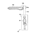
図1は、実施の形態に係るキーチェーン10の使用例を示す説明図である。キーチェーン10には、現実または非現実のキャラクタが視認可能な態様で表されている。非現実のキャラクタは例えばアニメーションや漫画や小説のキャラクタであってもよい。現実のキャラクタは例えば芸能人や俳優や歴史上の人物であってもよい。
ユーザ12は非使用状態のキーチェーン10を、スマートフォンや携帯電話やタブレットなどの携帯端末14、またはカバンやベルトに取り付けている。ユーザ12がキーチェーン10に表されるキャラクタと共にあるスポットを撮像する場合、まずキーチェーン10を外して使用状態に変形させる。次に図1に示されるようにユーザ12は片方の手で携帯端末14のカメラをスポットに向けて構え、もう片方の手で使用状態のキーチェーン10の持ち手部材を持ってキーチェーン10のキャラクタ部材がカメラの画角に入るようにする。その状態でユーザ12はカメラによる撮像を実行する。
図2は、実施の形態に係るキーチェーン10を用いて撮像した結果得られる画像16の一例を示す模式図である。画像16にはスポットの風景18と共に、キーチェーン10のキャラクタ部材102が映り込んでいる。図2にはユーザ12が手でキーチェーン10の持ち手部材104を持っている様子が示される。このように、本実施の形態に係るキーチェーン10を用いると、あたかもキャラクタ20がそのスポットにいるかのような画像16を得ることができる。
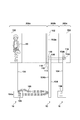
図3A~3Cは、キーチェーン10の構造図である。300aは、使用状態のキーチェーン10の正面図である。キーチェーン10は、板状のキャラクタ部材102と、棒状の持ち手部材104と、を備える。キャラクタ部材102はキャラクタ20を視覚的に表す部材である。キャラクタ部材102の表面には反射を抑制するための処理が施されてもよい。この場合、フラッシュ撮影の際の反射を抑制することができる。
持ち手部材104はキャラクタ部材102に回動可能に取り付けられる。持ち手部材104はキャラクタ部材102に対して360度回動可能であり、なんら回動トルクが加えられない状態ではキャラクタ部材102と持ち手部材104との相対位置は維持される。
キャラクタ部材102から遠位となる持ち手部材104の遠位端部104aは、チェーン106やストラップを取り付けることができるよう構成される。具体的には、遠位端部104aはL字形状に形成され、遠位端部104aにはチェーン106やストラップを通すための孔108が設けられている。ここで、チェーン106やストラップは、キーチェーン10を携帯端末14やカバンに取り付けるために用いられる部材である。撮像時、使用状態における持ち手部材104はグリップとして機能する。
300bは、使用状態のキーチェーン10の側面図である。300cは、使用状態のキーチェーン10の背面図である。キャラクタ部材102は、第一透明板110と、キャラクタ20の像が印刷されたシール112と、第二透明板114と、を含む。キャラクタ部材102は、第二透明板114の上面にシール112を貼り、さらにその上に第一透明板110を重ねて接着材により固定することで作成される。第一透明板110、第二透明板114はそれぞれ実質的に透明であればよく、例えばアクリル板や透明プラスチック板から作成されてもよい。このようにシール112を透明板110、114で挟み込む構造とすることにより、シール112が露出する場合と比較して、シール112の摩耗や損傷を低減し、キーチェーン10の製品寿命を延ばすことができる。
なお、本実施の形態ではキャラクタ20はキャラクタ20の像が印刷されたシールとして表されるが、これに限られず、例えば透明な板の面にキャラクタ20の像が直接描かれてもよい。
キャラクタ部材102と持ち手部材104との接続機構は、ねじ116と、スペーサ118と、を含む。接続機構はキャラクタ部材102の背面102a側に設けられ、特にキャラクタ部材102を正面から見たときにキャラクタ20によって隠される(または、キャラクタ20の像と重なる)位置に設けられる。あるいはまた、接続機構はキャラクタ20の像の下方に設けられてもよい。
スペーサ118はテフロン(登録商標)やゴムや金属等から形成されるドーナツ状の部材であり、キャラクタ部材102の背面102aと持ち手部材104の前面104bとの間に挟まれる。ねじ116は持ち手部材104とスペーサ118とキャラクタ部材102とを一体に締結する。ねじ116は、キャラクタ部材102により近い側の持ち手部材104の近位端部104cに設けられた孔と、スペーサ118の中心孔と、を通り、キャラクタ部材102に設けられた対応するねじ穴に螺合される。ねじ116の締め付けトルクと、スペーサ118のサイズや材質と、はキャラクタ部材102と持ち手部材104との相対運動が可能なように、かつ、直接的な外力が加えられていない場合にキャラクタ部材102と持ち手部材104との相対位置が維持されるように、選択される。
図3Bは、別の使用状態のキーチェーン10の正面図である。300aに示されるキーチェーン10の使用状態から、持ち手部材104をキャラクタ部材102に対して90度回動させることで、図3Bの状態が得られる。この状態は、画像の右上にキャラクタ20を表示させる際に便利である。300aの状態のキーチェーン10を用いて画像の右上にキャラクタ20を表示させようとすると、どうしても持ち手部材104とそれを持つ手とが画像に写り込んでしまう。これに対して図3Bの状態のキーチェーン10を用いる場合、画像の横からキャラクタ部材102を画角に入れることで、持ち手部材104やそれを持つ手が画像に写り込まないようにすることができる。
図3Cは、非使用状態のキーチェーン10の正面図である。300aに示されるキーチェーン10の使用状態から、持ち手部材104をキャラクタ部材102に対して180度回動させることで、図3Cの状態が得られる。キャラクタ部材102と持ち手部材104との相対位置がとりうる状態は、300aや図3Bに示される使用状態と、使用状態よりも持ち手部材104を把持しにくい非使用状態と、を含む。非使用状態では、図3Cに示されるように、持ち手部材104の一部はキャラクタ20の背面側に位置するようキャラクタ部材102と重なっている。持ち手部材104はキャラクタ部材102の背面に隠れているので、ユーザ12は持ち手部材104を持ちにくい。一方、非使用状態のキーチェーン10の全体の見た目は、通常のキーチェーンやキーホルダと似ており、キーチェーン10を携帯端末14やカバンに取り付けた際の違和感は低減または除去される。
キーチェーン10は、非使用状態において、持ち手部材104の遠位端部104aはキャラクタ部材102と重ならないよう構成される。これにより、非使用状態において、遠位端部104aに取り付けられたチェーン106とキャラクタ部材102との干渉を避ける得ることができる。
本実施の形態に係るキーチェーン10によると、使用状態のキーチェーン10のキャラクタ部材102全体を画角に入れても、持ち手部材104を持つ手は画角に入らない。したがって、キャラクタ20の全体を画像に入れつつ、持つ手は画像に入らないようにすることができる。
本実施の形態に係るキーチェーン10によると、例えば以下のような価値をユーザ12に提供することができる。ユーザ12は、非使用状態のキーチェーン10を携帯端末14やカバンに取り付けて外出する。ユーザ12は、外出先で写真を撮りたいスポットに遭遇した場合、キーチェーン10の持ち手部材104を180度回動させることで使用状態とする。ユーザ12は持ち手部材104を持ってキャラクタ20と一緒にスポットの写真を撮る。このように、ユーザ12は手軽にキャラクタ20とお出かけ先で写真を撮ることができる。また、キーチェーン10はグリップとして持ち手部材104を有しているので、撮影がより容易となる。さらに、非使用状態のキーチェーン10はコレクションしやすく、またカバンや携帯端末14に取り付けることができる。
以上、実施の形態に係るキーチェーン10について説明した。この実施の形態は例示であり、各構成要素や各処理の組み合わせにいろいろな変形例が可能なこと、またそうした変形例も本発明の範囲にあることは当業者に理解される。
実施の形態では、キャラクタ20の像が印刷されたシール112を用いるか、またはキャラクタ20の像を透明板に直接描く場合について説明したが、これに限られない。例えばキャラクタ20の立体像(例えば、フィギュアやぬいぐるみ)が用いられてもよい。
実施の形態では、キャラクタ部材102はキャラクタ20が見える正面とキャラクタ20が見えない背面102aとを有する場合について説明したが、これに限られない。例えばキャラクタ部材の両面にそれぞれキャラクタを描くことで、キャラクタ部材のどちら側から見てもキャラクタが見えるようにしてもよい。
実施の形態では、持ち手部材104はキャラクタ部材102に回動可能に取り付けられる場合について説明したが、これに限られない。例えば、キャラクタ部材の内部に持ち手部材が収まるスペースを設け、非使用状態において持ち手部材を該スペースに収容し、使用状態において持ち手部材をスペースから出すよう構成してもよい。あるいはまた、キャラクタ部材と持ち手部材とを折り畳み用のヒンジで接続し、非使用状態において折り畳むよう構成してもよい。
実施の形態では、携帯端末14のカメラでキャラクタ部材102のキャラクタ20を撮像する場合を説明したが、これに限られない。例えば、携帯端末14にインストールされたアプリケーションプログラムが携帯端末14の撮像機能を制御してもよい。この場合、該アプリケーションプログラムは、携帯端末14によって実行された場合、携帯端末14に、カメラに写っているキャラクタ20を特定する機能と、特定されたキャラクタ20の情報をインターネットなどのネットワークを介してサーバに送信する機能と、特定されたキャラクタ20に対応する画像をネットワークを介してサーバから受信する機能と、受信した画像をカメラに写る実空間の画像に合成する機能と、合成された画像を携帯端末14のディスプレイに表示させると共にメモリに格納する機能と、を実現させる。
実施の形態に係る技術的思想は以下の項目により表されてもよい。
(項目1)
第一部材とキャラクタを視覚的に表す第二部材とを備え、前記第一部材と前記第二部材との相対位置がとりうる状態が、第一状態と、第一状態よりも前記第一部材を把持しにくい第二状態と、を含む表示具。
(項目2)
前記第一部材は前記第二部材に回動可能に取り付けられる項目1に記載の表示具。
(項目3)
前記第二状態において前記第一部材は前記キャラクタの背面側に位置するよう前記第二部材と重なる項目1または2に記載の表示具。
(項目4)
前記第一状態において前記第二部材から遠位となる第一部材の端部は、前記表示具を他の物品に取り付けるために用いられる部材を取り付けることができるよう構成される項目1から3のいずれか一項に記載の表示具。
(項目5)
前記第一状態において前記第二部材から遠位となる第一部材の端部は、第二状態において前記第二部材と重ならない項目1から4のいずれか一項に記載の表示具。
(項目6)
前記第一部材と前記第二部材との接続機構は、前記第一部材と前記第二部材との相対運動が可能なように、かつ、直接的な外力が加えられていない場合に前記第一部材と前記第二部材との相対位置が維持されるように、構成される項目1から5のいずれか一項に記載の表示具。
(項目7)
前記第一状態において前記第二部材は携帯端末により撮像され、
前記第二状態において前記表示具は他の物品に取り付けられる項目1から6のいずれか一項に記載の表示具。
(項目8)
前記第二部材は前記キャラクタの像が貼られたかまたは描かれた実質的に透明な板を含む項目1から7のいずれか一項に記載の表示具。
(項目9)
前記端部はL字形状に形成される項目4または5に記載の表示具。
(項目10)
項目7に記載される携帯端末であって、
前記キャラクタが撮像されると、撮像された前記キャラクタに対応する画像を実空間の画像に合成する手段を備える携帯端末。
本発明は上記実施の形態に制限されるものではなく、本発明の精神及び範囲から離脱することなく、様々な変更及び変形が可能である。従って、本発明の範囲を公にするために、以下の請求項を添付する。
本願は、2017年12月20日提出の日本国特許出願特願2017-244377を基礎として優先権を主張するものであり、その記載内容の全てを、ここに援用する。
Claims (7)
- 第一部材とキャラクタを視覚的に表す第二部材とを備え、前記第一部材と前記第二部材との相対位置がとりうる状態が、第一状態と、第一状態よりも前記第一部材を把持しにくい第二状態と、を含む表示具。
- 前記第一部材は前記第二部材に回動可能に取り付けられる請求項1に記載の表示具。
- 前記第二状態において前記第一部材は前記キャラクタの背面側に位置するよう前記第二部材と重なる請求項1または2に記載の表示具。
- 前記第一状態において前記第二部材から遠位となる第一部材の端部は、前記表示具を他の物品に取り付けるために用いられる部材を取り付けることができるよう構成される請求項1から3のいずれか一項に記載の表示具。
- 前記第一状態において前記第二部材から遠位となる第一部材の端部は、第二状態において前記第二部材と重ならない請求項1から4のいずれか一項に記載の表示具。
- 前記第一部材と前記第二部材との接続機構は、前記第一部材と前記第二部材との相対運動が可能なように、かつ、直接的な外力が加えられていない場合に前記第一部材と前記第二部材との相対位置が維持されるように、構成される請求項1から5のいずれか一項に記載の表示具。
- 前記第一状態において前記第二部材は携帯端末により撮像され、
前記第二状態において前記表示具は他の物品に取り付けられる請求項1から6のいずれか一項に記載の表示具。
Priority Applications (1)
| Application Number | Priority Date | Filing Date | Title |
|---|---|---|---|
| US16/815,532 US20200206649A1 (en) | 2017-12-20 | 2020-03-11 | Display tool |
Applications Claiming Priority (2)
| Application Number | Priority Date | Filing Date | Title |
|---|---|---|---|
| JP2017244377A JP7137803B2 (ja) | 2017-12-20 | 2017-12-20 | 表示具 |
| JP2017-244377 | 2017-12-20 |
Related Child Applications (1)
| Application Number | Title | Priority Date | Filing Date |
|---|---|---|---|
| US16/815,532 Continuation US20200206649A1 (en) | 2017-12-20 | 2020-03-11 | Display tool |
Publications (1)
| Publication Number | Publication Date |
|---|---|
| WO2019123685A1 true WO2019123685A1 (ja) | 2019-06-27 |
Family
ID=66993326
Family Applications (1)
| Application Number | Title | Priority Date | Filing Date |
|---|---|---|---|
| PCT/JP2018/021858 WO2019123685A1 (ja) | 2017-12-20 | 2018-06-07 | 表示具 |
Country Status (3)
| Country | Link |
|---|---|
| US (1) | US20200206649A1 (ja) |
| JP (1) | JP7137803B2 (ja) |
| WO (1) | WO2019123685A1 (ja) |
Citations (4)
| Publication number | Priority date | Publication date | Assignee | Title |
|---|---|---|---|---|
| JPH0713224A (ja) * | 1993-06-23 | 1995-01-17 | Yoshiyuki Takematsu | 模擬被写体同時撮影用具 |
| US5538166A (en) * | 1994-12-14 | 1996-07-23 | Matsuri Corporation | Combination plush doll and hanger assembly |
| JP3130223U (ja) * | 2006-11-24 | 2007-03-22 | メルヘンワールド株式会社 | キーホルダー |
| WO2010035462A1 (ja) * | 2008-09-24 | 2010-04-01 | 東京メタル株式会社 | 着脱自在式ハンガー |
-
2017
- 2017-12-20 JP JP2017244377A patent/JP7137803B2/ja active Active
-
2018
- 2018-06-07 WO PCT/JP2018/021858 patent/WO2019123685A1/ja active Application Filing
-
2020
- 2020-03-11 US US16/815,532 patent/US20200206649A1/en not_active Abandoned
Patent Citations (4)
| Publication number | Priority date | Publication date | Assignee | Title |
|---|---|---|---|---|
| JPH0713224A (ja) * | 1993-06-23 | 1995-01-17 | Yoshiyuki Takematsu | 模擬被写体同時撮影用具 |
| US5538166A (en) * | 1994-12-14 | 1996-07-23 | Matsuri Corporation | Combination plush doll and hanger assembly |
| JP3130223U (ja) * | 2006-11-24 | 2007-03-22 | メルヘンワールド株式会社 | キーホルダー |
| WO2010035462A1 (ja) * | 2008-09-24 | 2010-04-01 | 東京メタル株式会社 | 着脱自在式ハンガー |
Also Published As
| Publication number | Publication date |
|---|---|
| JP7137803B2 (ja) | 2022-09-15 |
| US20200206649A1 (en) | 2020-07-02 |
| JP2019110931A (ja) | 2019-07-11 |
Similar Documents
| Publication | Publication Date | Title |
|---|---|---|
| US20150346590A1 (en) | Branded monopod apparatus | |
| EP3076265A3 (en) | Foldable phone with flexible display comprising a slidable back cover | |
| DE602005026598D1 (de) | Klappbares, tragbares Endgerät mit ausziehbarem Kameramodul | |
| US20170223236A1 (en) | Wearable Camera Apparatus | |
| CN207720213U (zh) | 手机自拍杆 | |
| US20160295173A1 (en) | Digital camcorder angle display viewer device with an add-on protective cover for a mobile device and method for transporting components thereof | |
| US20210124389A1 (en) | Super smartphone | |
| KR101919051B1 (ko) | 디스플레이부 힌지 회전 모바일 단말기 | |
| WO2019123685A1 (ja) | 表示具 | |
| KR101731889B1 (ko) | 가상현실 장치로 전환되는 휴대 단말 케이스 | |
| CN108810387B (zh) | 多功能摄像头 | |
| JP7549186B2 (ja) | スーパースマートフォン及びスマートフォンシステム | |
| JP2009288613A5 (ja) | ||
| JP2009045160A (ja) | 撮像装置用ケース | |
| KR101642239B1 (ko) | 휴대용 전자기기의 촬영 보조기구 | |
| CN105005170A (zh) | 折叠式臂式照相机架 | |
| CN211630223U (zh) | 一种便于手机拍摄的防光壳 | |
| JP3217153U (ja) | タブレット型端末収納ケース | |
| JP2005010410A (ja) | 表示装置 | |
| JP3125858U (ja) | 携帯機器ホルダ | |
| JP2003131755A (ja) | 携帯型通信端末装置 | |
| JP3014575U (ja) | カメラケース | |
| US9002187B1 (en) | Handheld subject framing apparatus for photograph | |
| WO2016073993A1 (en) | Camera accessory for use with a mobile device | |
| KR20150000833U (ko) | 스마트폰 커버의 촬영보조 기능 |
Legal Events
| Date | Code | Title | Description |
|---|---|---|---|
| 121 | Ep: the epo has been informed by wipo that ep was designated in this application |
Ref document number: 18890912 Country of ref document: EP Kind code of ref document: A1 |
|
| NENP | Non-entry into the national phase |
Ref country code: DE |
|
| 122 | Ep: pct application non-entry in european phase |
Ref document number: 18890912 Country of ref document: EP Kind code of ref document: A1 |