WO2019116793A1 - 車載システム、及び、検出器ハブ - Google Patents
車載システム、及び、検出器ハブ Download PDFInfo
- Publication number
- WO2019116793A1 WO2019116793A1 PCT/JP2018/041513 JP2018041513W WO2019116793A1 WO 2019116793 A1 WO2019116793 A1 WO 2019116793A1 JP 2018041513 W JP2018041513 W JP 2018041513W WO 2019116793 A1 WO2019116793 A1 WO 2019116793A1
- Authority
- WO
- WIPO (PCT)
- Prior art keywords
- vehicle
- detector
- detectors
- control device
- network
- Prior art date
- Legal status (The legal status is an assumption and is not a legal conclusion. Google has not performed a legal analysis and makes no representation as to the accuracy of the status listed.)
- Ceased
Links
Images


Classifications
-
- B—PERFORMING OPERATIONS; TRANSPORTING
- B60—VEHICLES IN GENERAL
- B60R—VEHICLES, VEHICLE FITTINGS, OR VEHICLE PARTS, NOT OTHERWISE PROVIDED FOR
- B60R16/00—Electric or fluid circuits specially adapted for vehicles and not otherwise provided for; Arrangement of elements of electric or fluid circuits specially adapted for vehicles and not otherwise provided for
- B60R16/02—Electric or fluid circuits specially adapted for vehicles and not otherwise provided for; Arrangement of elements of electric or fluid circuits specially adapted for vehicles and not otherwise provided for electric constitutive elements
- B60R16/023—Electric or fluid circuits specially adapted for vehicles and not otherwise provided for; Arrangement of elements of electric or fluid circuits specially adapted for vehicles and not otherwise provided for electric constitutive elements for transmission of signals between vehicle parts or subsystems
- B60R16/0238—Electrical distribution centers
-
- H—ELECTRICITY
- H04—ELECTRIC COMMUNICATION TECHNIQUE
- H04L—TRANSMISSION OF DIGITAL INFORMATION, e.g. TELEGRAPHIC COMMUNICATION
- H04L12/00—Data switching networks
- H04L12/28—Data switching networks characterised by path configuration, e.g. LAN [Local Area Networks] or WAN [Wide Area Networks]
- H04L12/40—Bus networks
- H04L12/40169—Flexible bus arrangements
- H04L12/40176—Flexible bus arrangements involving redundancy
- H04L12/40189—Flexible bus arrangements involving redundancy by using a plurality of bus systems
-
- G—PHYSICS
- G01—MEASURING; TESTING
- G01S—RADIO DIRECTION-FINDING; RADIO NAVIGATION; DETERMINING DISTANCE OR VELOCITY BY USE OF RADIO WAVES; LOCATING OR PRESENCE-DETECTING BY USE OF THE REFLECTION OR RERADIATION OF RADIO WAVES; ANALOGOUS ARRANGEMENTS USING OTHER WAVES
- G01S13/00—Systems using the reflection or reradiation of radio waves, e.g. radar systems; Analogous systems using reflection or reradiation of waves whose nature or wavelength is irrelevant or unspecified
- G01S13/86—Combinations of radar systems with non-radar systems, e.g. sonar, direction finder
-
- G—PHYSICS
- G05—CONTROLLING; REGULATING
- G05D—SYSTEMS FOR CONTROLLING OR REGULATING NON-ELECTRIC VARIABLES
- G05D1/00—Control of position, course, altitude or attitude of land, water, air or space vehicles, e.g. using automatic pilots
- G05D1/0088—Control of position, course, altitude or attitude of land, water, air or space vehicles, e.g. using automatic pilots characterized by the autonomous decision making process, e.g. artificial intelligence, predefined behaviours
-
- H—ELECTRICITY
- H04—ELECTRIC COMMUNICATION TECHNIQUE
- H04L—TRANSMISSION OF DIGITAL INFORMATION, e.g. TELEGRAPHIC COMMUNICATION
- H04L12/00—Data switching networks
- H04L12/28—Data switching networks characterised by path configuration, e.g. LAN [Local Area Networks] or WAN [Wide Area Networks]
- H04L12/40—Bus networks
-
- H—ELECTRICITY
- H04—ELECTRIC COMMUNICATION TECHNIQUE
- H04L—TRANSMISSION OF DIGITAL INFORMATION, e.g. TELEGRAPHIC COMMUNICATION
- H04L12/00—Data switching networks
- H04L12/66—Arrangements for connecting between networks having differing types of switching systems, e.g. gateways
-
- H—ELECTRICITY
- H05—ELECTRIC TECHNIQUES NOT OTHERWISE PROVIDED FOR
- H05K—PRINTED CIRCUITS; CASINGS OR CONSTRUCTIONAL DETAILS OF ELECTRIC APPARATUS; MANUFACTURE OF ASSEMBLAGES OF ELECTRICAL COMPONENTS
- H05K7/00—Constructional details common to different types of electric apparatus
- H05K7/02—Arrangements of circuit components or wiring on supporting structure
- H05K7/026—Multiple connections subassemblies
-
- H—ELECTRICITY
- H01—ELECTRIC ELEMENTS
- H01R—ELECTRICALLY-CONDUCTIVE CONNECTIONS; STRUCTURAL ASSOCIATIONS OF A PLURALITY OF MUTUALLY-INSULATED ELECTRICAL CONNECTING ELEMENTS; COUPLING DEVICES; CURRENT COLLECTORS
- H01R2201/00—Connectors or connections adapted for particular applications
- H01R2201/26—Connectors or connections adapted for particular applications for vehicles
-
- H—ELECTRICITY
- H04—ELECTRIC COMMUNICATION TECHNIQUE
- H04L—TRANSMISSION OF DIGITAL INFORMATION, e.g. TELEGRAPHIC COMMUNICATION
- H04L12/00—Data switching networks
- H04L12/28—Data switching networks characterised by path configuration, e.g. LAN [Local Area Networks] or WAN [Wide Area Networks]
- H04L12/40—Bus networks
- H04L2012/40267—Bus for use in transportation systems
- H04L2012/40273—Bus for use in transportation systems the transportation system being a vehicle
Definitions
- the present invention relates to an in-vehicle system and a detector hub.
- Patent Document 1 discloses an in-vehicle information system that configures a network that can mutually communicate with each other through a plurality of communication interfaces between a plurality of devices mounted in the vehicle. It is done.
- the present invention has been made in view of the above-described circumstances, and an object thereof is to provide an on-vehicle system and a detector hub capable of securing appropriate communication.
- an in-vehicle system includes: a plurality of detectors provided in a vehicle; and an in-vehicle device mounted on the vehicle based on detection information indicating detection results by the plurality of detectors.
- a controller for controlling a plurality of detectors, and the plurality of detectors and the controller so as to be mutually communicable, and a detector hub for collecting the detection information by the plurality of detectors and transmitting the information to the controller And.
- a first network for communicably connecting the in-vehicle device and the control device, a network independent of the first network, and the plurality of detectors and the detector hub
- a second network communicably connecting to the control device may be provided.
- the plurality of detector hubs are provided, and the detection information by the plurality of mutually different detectors is collected, and the second network mutually communicates the plurality of detector hubs A ring network connected as much as possible can be configured.
- the detector hub may include an abnormality determination unit that determines an abnormality of the detector.
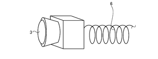
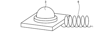
- the on-vehicle system may further include a curl cord connecting the detector hub and the detector.
- a detector hub includes a detector connection portion communicably connected to a plurality of detectors provided in a vehicle, and detection results obtained by the plurality of detectors.
- a control device connecting unit communicably connected to a control device for controlling the on-vehicle device mounted on the vehicle based on the detection information representing the detection information collected by the plurality of detectors and the control device And a communication processing unit for transmitting data.
- the on-vehicle system and the detector hub according to the present invention are configured such that a plurality of detectors and a control device can communicate with each other via the detector hub.
- the detector hub aggregates detection information from the plurality of detectors and transmits the information to the control device.
- the in-vehicle system and the detector hub have an effect that proper communication can be ensured.
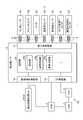
- FIG. 1 is a block diagram showing a schematic configuration of a vehicle-mounted system according to the embodiment.
- FIG. 2 is a block diagram for explaining the arrangement of a plurality of detector hubs provided in the in-vehicle system according to the embodiment.
- FIG. 3 is a block diagram showing a schematic configuration of a detector hub provided in the in-vehicle system according to the embodiment.
- FIG. 4 is a schematic perspective view showing an example of a curled cord provided in the in-vehicle system according to the embodiment.
- FIG. 5 is a schematic perspective view showing an example of a curled cord provided in the in-vehicle system according to the embodiment.
- FIG. 6 is a schematic perspective view showing an example of a curled cord provided in the in-vehicle system according to the embodiment.
- the in-vehicle system 1 of the present embodiment shown in FIG. 1 is an in-vehicle network system which is mounted on a vehicle V and in which the plurality of detectors 3 are integrated by the detector hub 5 in the vehicle V.
- the on-vehicle system 1 is realized by mounting the components shown in FIG.
- the configuration of the in-vehicle system 1 will be described in detail with reference to the drawings.
- connection method between each component for supplying and receiving the power supply, control signal, various information and the like is a wiring material such as an electric wire or an optical fiber unless otherwise noted.
- the connection may be wired (for example, including optical communication via an optical fiber) via wireless communication, wireless communication, wireless connection such as non-contact power feeding, or the like.
- the vehicle V to which the in-vehicle system 1 is applied is any of an electric vehicle (EV), a hybrid vehicle (HEV), a plug-in hybrid vehicle (PHEV), a gasoline vehicle, a diesel vehicle, etc. using a motor or engine as a drive source. It may be a vehicle.
- FIG. 1, FIG. 2, and FIG. 3 which are explained below are illustrated in a state in which all or a part of a plurality of provided detector hubs 5 is abbreviated as “HUB”.
- the in-vehicle system 1 includes a plurality of in-vehicle devices 2, a plurality of detectors 3, a control device 4, a detector hub 5, and a curl cord 6. Prepare. Further, the in-vehicle system 1 includes a first network N1 and a second network N2 as an in-vehicle LAN (Local Area Network) that communicably connects them.
- LAN Local Area Network
- the in-vehicle device 2 is a device mounted on the vehicle V to realize various functions.
- a plurality of in-vehicle devices 2 are provided in the vehicle V.
- the plurality of on-vehicle devices 2 may be installed on the vehicle V at the time of manufacturing the vehicle V, for example, or may be a so-called after-sales product installed on the vehicle V retrofitted after the vehicle V is manufactured.
- the plurality of in-vehicle devices 2 may include, for example, traveling system actuators, power supply devices, vehicle environment devices, multimedia (Multi Media) devices, and the like.
- the travel system actuator includes, for example, a power train for travel (engine, motor generator, transmission) which is a drive device for traveling the vehicle V, a steering device for steering the vehicle V, a braking device for braking the vehicle V, etc. It may be.
- the power supply devices may include, for example, storage devices such as batteries, capacitors and capacitors, an alternator, a motor generator, a power distribution unit, a power supply switching mechanism, a power control box, an inverter, a converter, and the like.
- the vehicle environment related devices may include, for example, various lighting devices such as headlights, tail lamps, and room lights, air conditioners, wiper devices, mirrors, sheets, and the like.
- the multimedia-based device may include, for example, devices such as navigation devices, audio, meters, and various displays.
- the plurality of in-vehicle devices 2 shown in FIG. 1 are, for example, an automatic transmission (AT) 2A, lights 2B, an engine 2C, a brake 2D, a steering 2E, a door 2F, a meter 2G, an A / C (air conditioner) 2H, A seat 2I, a lock 2J, a front seat display 2K, a TV / radio antenna 2L, an audio 2M, a rear seat display 2N, an airbag 20, an occupant detector 2P, a seat belt 2Q and the like are illustrated. Is not limited to this.
- the AT 2A constitutes the above-mentioned transmission.
- the light 2B constitutes the above-described lighting device.
- the engine 2C is an internal combustion engine and generates motive power for traveling and motive power for driving accessories.
- the brake 2D constitutes the above-described braking device.
- the steering 2E constitutes the above-described steering device.
- the door 2F is attached to the vehicle body of the vehicle V in an openable / closable manner, and includes an electric power window and the like.
- the meter 2G displays various measurement values and information in the vehicle V.
- a / C (air conditioner) 2H constitutes the above-described air conditioner.
- the seat 2I is provided in the vehicle of the vehicle V and can be seated by an occupant, and includes various adjustment mechanisms, a heater, and the like.
- the lock 2J locks the door 2F.
- the front seat display 2 ⁇ / b> K is provided on the front seat side of the vehicle V in the vehicle and displays various images.
- the TV / radio antenna 2L is an antenna for receiving radio waves of TV and radio.
- the audio 2M is for outputting hearing information and music such as voice information and sound information.
- the rear seat display 2 ⁇ / b> N is provided on the rear seat side of the vehicle V and displays various images.
- the airbag 20 is a safety device that is deployed at the time of a collision to protect an occupant.
- the occupant detector 2P is for detecting an occupant according to the presence or absence of seating on the seat 2I.
- the seat belt 2Q is a safety device that restrains the occupant on the seat 2I.
- the detector 3 is mounted on the vehicle V and detects various information.
- a plurality of detectors 3 are provided in the vehicle V.
- the plurality of detectors 3 are, for example, a vehicle speed sensor, an acceleration sensor, a steering angle sensor, an accelerator sensor, a brake sensor, a shift position sensor, an air bag deployment switch, a winker switch, a seat belt switch, a seat load sensor, a rain sensor, a humidity sensor
- Image sensors such as temperature sensors, current / voltage meters, and CCD cameras, various radars and sonars using infrared rays, millimeter waves, ultrasonic waves and the like, GPS receivers, various wireless communication devices and the like may be included.
- the automatic driving system detection device typically includes a detector for monitoring the surroundings of the vehicle V.
- the plurality of detectors 3 are millimeter wave radar 3A, stereo camera 3B, lidar 3C, ultrasonic sensor 3D, wheel speed sensor 3E, tire pressure sensor 3F, road surface state detection sensor 3G, etc. as automatic driving system detection devices.
- the present invention is not limited to this.
- the millimeter wave radar 3A detects an object present around the vehicle V by millimeter wave radio waves.
- the stereo camera 3B captures a stereoscopic image (three-dimensional image) around the vehicle V.
- the lidar 3C is a so-called laser radar, which detects an object present around the vehicle V by laser light.
- the ultrasonic sensor 3D detects an object present around the vehicle V by ultrasonic waves.
- the wheel speed sensor 3E detects the rotational speed of the wheel of the vehicle V.
- the tire pressure sensor 3F detects the air pressure of a tire mounted on the wheel of the vehicle V.
- the road surface state detection sensor 3G detects the state of the road surface on which the wheels of the vehicle V come in contact with the ground.
- the detector 3 outputs detection information representing a detection result to the control device 4 via the detector hub 5 and the like.
- the control device 4 controls each part of the in-vehicle system 1 in an integrated manner.
- the control device 4 executes various arithmetic processing for controlling the in-vehicle device 2 mounted on the vehicle V based on detection information representing detection results by the plurality of detectors 3.
- the control device 4 is a central processing unit such as a central processing unit (CPU), a micro processing unit (MPU), an application specific integrated circuit (ASIC), a field programmable gate array (FPGA), a read only memory (ROM), a RAM (RAM). It comprises an electronic circuit based on a known microcomputer including a Random Access Memory) and an interface.
- the control device 4 executes various programs and applications stored in the storage unit, and when the programs and applications operate, outputs an output signal to each unit to execute various processes for realizing various functions.
- the control device 4 is configured of a plurality of ECUs (Electronic Control Units).
- the control device 4 shown in FIG. 1 is, by way of example, fault diagnosis ECU 4A, vehicle stability control ECU 4B, ATECU 4C, light ECU 4D, engine ECU 4E, brake ECU 4F, steering ECU 4G, body ECU 4H, door ECU 4I, meter ECU 4J, meter ECU 4J, A / CECU 4K, seat ECU 4L.
- the failure diagnosis ECU 4A executes a process of diagnosing a failure of the in-vehicle device 2.
- the vehicle stability control ECU 4B executes processing for stabilizing the posture of the vehicle V.
- the ATECU 4C controls the operation of the AT 2A.
- the light ECU 4D controls the operation of the light 2B.
- the engine ECU 4E controls the operation of the engine 2C.
- the brake ECU 4F controls the operation of the brake 2D.
- the steering ECU 4G controls the operation of the steering 2E.
- the body ECU 4H performs overall control of the body system of the vehicle V.
- the door ECU 4I controls the operation of the electric power window or the like of the door 2F.
- the meter ECU 4J controls the operation of the meter 2G.
- the A / CECU 4K controls the operation of the A / C 2H.
- the seat ECU 4L controls the operation of the seat 2I.
- the keyless ECU 4M controls the operation of the lock 2J.
- the front seat display ECU 4N controls the operation of the front seat display 2K.
- the TV / radio tuner 4O is a tuning circuit that selects radio waves of a specific frequency from radio waves related to TV / radio etc. received by the TV / radio antenna 2L.
- the stereo amplifier 4P is an amplification circuit that amplifies an electrical signal corresponding to the auditory information and outputs the amplified signal from the audio 2M.
- the rear seat display ECU 4Q controls the operation of the rear seat display 2N.
- the navigation ECU 4R executes a process related to the navigation of the vehicle V.
- the navigation ECU 4R is based on, for example, information on vehicle position / positioning (GPS) of the vehicle V acquired by the communication module 4Ra performing communication with the outside of the vehicle V, map road / traffic information (big data from outside the vehicle), etc.
- GPS vehicle position / positioning
- a process related to navigation of the vehicle V is performed.
- the airbag ECU 4S controls the operation of the airbag 2O.
- the occupant detection ECU 4T executes processing for detecting an occupant based on the output of the occupant detector 2P.
- the seat belt ECU 4U controls the operation of the seat belt 2Q.
- the detected information processing ECU 4V executes various processes on the detection information by the plurality of detectors 3.
- the detection information processing ECU 4V executes various processing such as detection of the traveling environment of the vehicle V, detection of an obstacle around the vehicle V, detection of a white line, and the like based on detection information by the plurality of detectors 3, for example.
- the detector hub 5 is a concentrator that aggregates connection destinations of a plurality of detectors 3.
- the detector hub 5 intervenes in a mutually communicable manner between the plurality of detectors 3 and the control device 4.
- the detector hub 5 is interposed between the plurality of detectors 3 and the detected information processing ECU 4V of the control device 4.
- the detector hub 5 has a function of aggregating detection information of the plurality of detectors 3 and transmitting the information to the detection information processing ECU 4V of the control device 4.
- a plurality of detector hubs 5 of the present embodiment are provided on the vehicle V and are communicably connected to each other.
- a total of four detector hubs 5 are provided, one each on the front left side, the front right side, the rear left side, and the rear right side where the detectors 3 tend to be concentrated.
- a plurality of, here, four detector hubs 5 aggregate detection information by a plurality of mutually different detectors 3. Since the plurality of detector hubs 5 have substantially the same configuration, in the following description, each of the detector hubs 5 will be described in common unless otherwise specified.
- the detector hub 5 includes a detector connection unit 51, a control device connection unit 52, a hub connection unit 53, and a processing unit 54.
- the detector connection unit 51 is a portion communicably connected to the plurality of detectors 3.
- the control device connection unit 52 is a portion communicably connected to the detection information processing ECU 4V of the control device 4.
- the hub connection portion 53 is a portion communicably connected to the other detector hubs 5.
- the detector connection unit 51, the control device connection unit 52, and the hub connection unit 53 are interfaces for transmitting and receiving various information to and from each unit.
- the detector connection unit 51, the control device connection unit 52, and the hub connection unit 53 each have a function of performing wired communication of information with each unit via an electric wire etc., and information via a wireless communication unit etc. with each unit And the like.
- the detector connection unit 51, the control device connection unit 52, and the hub connection unit 53 are illustrated as being connected by wire and the like to each unit as an example. And here, the detector connection part 51 and each detector 3 are wire-connected by the curl cord 6.
- the curled cord 6 is a wire which is spirally wound and stretchable along the extending direction as illustrated in FIGS. 4, 5 and 6.
- the respective curled cords 6 wire-connect the detector connection 51 of the detector hub 5 and the detector 3 in a mutually communicable manner.
- the processing unit 54 is a part having a function capable of executing processing of aggregating detection information by the plurality of detectors 3 and transmitting the information to the detection information processing ECU 4V of the control device 4.
- the processing unit 54 also has a function capable of executing a process of determining an abnormality of the detector 3.
- the processing unit 54 is configured to include a well-known microcomputer-based electronic circuit including a central processing unit such as a CPU, an MPU, an ASIC, and an FPGA, a ROM, a RAM, and an interface.
- the processing unit 54 is connected to the detector connection unit 51, the control device connection unit 52, and the hub connection unit 53.
- the processing unit 54 can exchange various electrical signals with each other.
- the processing unit 54 functionally and conceptually includes a storage unit 54 a, a communication processing unit 54 b, and an abnormality determination unit 54 c.
- the storage unit 54a is a storage device such as a memory.
- the storage unit 54a stores conditions and information necessary for various processes in the processing unit 54, various programs and applications to be executed by the processing unit 54, control data, and the like.
- the storage unit 54a can also temporarily store various information detected by the detector 3. In the storage unit 54a, such information is read out by the processing unit 54 and the like as needed.
- the processing unit 54 executes various programs stored in the storage unit 54 a based on various input signals and the like, and outputs various output signals to the respective units when the program operates to realize various functions. Execute the process
- the communication processing unit 54 b can execute processing of aggregating detection information by the plurality of detectors 3 and collectively transmitting the detection information to the detection information processing ECU 4 V of the control device 4. For example, the communication processing unit 54 b receives detection information by the plurality of detectors 3 via the detector connection unit 51, and collects and stores the information once in the storage unit 54 a. Then, the communication processing unit 54b collectively detects the detection information of each detector 3 collected and stored in the storage unit 54a for each fixed data frame through the control device connection unit 52 at a fixed timing in a batch. Transmit to the information processing ECU 4V.
- the abnormality determination unit 54c can execute the process of determining an abnormality of the detector 3.
- the abnormality determination unit 54 c determines the abnormality of the detector 3 based on, for example, the abnormality determination threshold.
- the abnormality determination threshold is a threshold set in advance for the detection signal corresponding to the detection information of each detector 3.
- the abnormality determination unit 54c is stored in the storage unit 54a.
- the abnormality determination threshold value is set to, for example, a relatively large value as compared with a physical quantity (a current value, a voltage value, and the like) according to a detection signal in a state where the detector 3 is used in normal use.
- the abnormality determination unit 54c determines that the detector 3 is normal when the physical amount corresponding to the detection signal of the detector 3 is less than the abnormality determination threshold. On the other hand, the abnormality determination unit 54c determines that the detector 3 is abnormal when the physical quantity corresponding to the detection signal of the detector 3 becomes equal to or more than the abnormality determination threshold. Then, the communication processing unit 54b according to the present embodiment, for example, excludes detection information of the detector 3 determined to be abnormal by the abnormality determination unit 54c from the information group collectively transmitted to the detected information processing ECU 4V. Thus, the communication processing unit 54b does not transmit the detection information of the detector 3 determined to be abnormal by the abnormality determination unit 54c to the detected information processing ECU 4V.
- the communication processing unit 54b may further transmit detector abnormality information indicating that the detector 3 is abnormal to the detected information processing ECU 4V.
- abnormality determination of the detector 3 by the abnormality determination part 54c is not restricted to said method, Various well-known methods can be used.
- the on-vehicle device 2 and the control device 4 are communicably connected to each other by the first network N1.
- the first network N1 is a communication network that communicably connects the in-vehicle device 2 and the control device 4 to each other.
- the first network N1 can use any communication network, whether wired or wireless.
- the first network N1 of the present embodiment is configured to include a powertrain chassis LANN11, a body LANN12, an information LANN13, a safety LANN14, and an inter-network connection unit N10.
- the powertrain-chassis LANN 11 is a network that mainly performs communication between devices related to behavior control of the vehicle V.
- the failure diagnosis ECU 4A, the vehicle stability control ECU 4B, the ATECU 4C, the light ECU 4D, the engine ECU 4E, the brake ECU 4F, and the steering ECU 4G are communicably connected.
- the body system LANN 12 is a network that mainly performs communication between devices related to the control of the interior of the vehicle V.
- the body ECU 4H, the door ECU 4I, the meter ECU 4J, the A / C ECU 4K, the seat ECU 4L, and the keyless ECU 4M are communicably connected.
- the information system LAN N13 is a network that mainly performs communication between multimedia / entertainment devices of the vehicle V.
- the front seat display ECU 4N, the TV / radio tuner 4O, the stereo amplifier 4P, the rear seat display ECU 4Q, and the navigation ECU 4R are communicably connected.
- the information system LANN 13 can communicate with the front seat display 2K, the TV / radio antenna 2L, the audio 2M, and the rear seat display 2N to the front seat display ECU 4N, the TV / radio tuner 4O, the stereo amplifier 4P, and the rear seat display ECU 4Q, respectively.
- the safety system LANN 14 is a network that mainly performs communication between devices involved in safety control of the vehicle V.
- the safety system LANN 14 is communicably connected to the air bag ECU 4S, the occupant detection ECU 4T, the seat belt ECU 4U, and the detected information processing ECU 4V.
- the safety system LANN 14 is communicably connected to the airbag ECU 4S, the occupant detection ECU 4T, and the seat belt ECU 4U, respectively, so that the airbag 2O, the occupant detector 2P, and the seat belt 2Q can be communicated.
- the inter-network connection unit N10 communicably connects the powertrain chassis LANN11, the body LANN12, the information LANN13, and the safety LANN14.
- the inter-network connection unit N10 has a function as a protocol conversion unit (so-called G / W (Gateway: Function) function unit) that performs protocol conversion, and a function as a trunk bus connecting between the networks.
- the first network N1 communicably connects the powertrain chassis LANN11, the body LANN12, the information LANN13, and the safety LANN14 with a plurality of different protocols via an inter-network connection N10.
- the inter-network connection unit N10 converts the protocol between networks of different protocols and distributes information to each network.
- a protocol used in the first network N1 for example, CAN communication, CAN-FD, LIN, CXPI, NFC, Giga-IR, UWB, Ethernet (registered trademark), HDMI (registered trademark), DSI, wireless transmission communication, Various communication protocols related to USB 3.0, Transfer Jet (registered trademark), HomePlug-GreenPHY, wireless LAN communication, submillimeter wave communication, power line communication (PLC), short range wireless communication, weak radio wave communication, etc. may be mentioned. It is not limited.
- the functional arrangement of the G / W functional unit functioning as a protocol conversion unit is not limited to the central functional arrangement as shown in FIG. 1, but is an area distributed functional arrangement and a domain distributed functional arrangement It is also good.
- the central type functional arrangement is an arrangement of the vehicle V in which the G / W function units are concentrated at one place.
- the area distribution type function arrangement is an arrangement form in which the G / W function units are respectively dispersed and arranged in an arbitrary area in the vehicle V, and the plurality of G / W function units are linked.
- the domain distribution type functional arrangement is an arrangement of the vehicle V in which the G / W function units are respectively distributed and arranged for each arbitrary domain and the plurality of G / W function units are linked.
- the second network N2 is a network different from the first network N1, and is a network of another system independent of the first network N1.
- the second network N2 is a communication network dedicated to a detection system that communicably connects the plurality of detectors 3, the detector hub 5, and the control device 4 to each other. More specifically, the second network N2 communicably connects the plurality of detectors 3 and the detector hub 5 to each other. In addition, the second network N2 communicably connects the plurality of detector hubs 5 to each other. Furthermore, the second network N2 communicably connects the detector hub 5 and the control device 4 to each other.
- the second network N2 may use any communication network, whether wired or wireless.
- the above-described curl code 6 constitutes a part of the second network N2.
- the second network N2 configures a ring network in which a plurality of detector hubs 5 are communicably connected to each other. That is, the second network N2 is configured by a so-called ring topology in which a plurality of detector hubs 5, here four detector hubs 5 are nodes.
- the second network N2 communicably connects a plurality of different detectors 3 to the plurality of detector hubs 5, respectively. Then, the second network N2 communicably connects the two detector hubs 5 on the vehicle front side among the plurality of detector hubs 5 with the detection information processing ECU 4V of the control device 4.
- the second network N2 of the present embodiment does not include a protocol conversion unit such as the inter-network connection unit N10, and a plurality of detectors 3, a detector hub 5, and a control device by a single protocol, for example, Ethernet. And 4 are communicably connected to each other.
- the in-vehicle system 1 and the detector hub 5 described above are configured such that the plurality of detectors 3 and the control device 4 can communicate with each other with the detector hub 5 interposed.
- the detector hub 5 aggregates detection information from the plurality of detectors 3 and transmits the information to the control device 4.
- the on-vehicle system 1 tends to be required to be equipped with a wide variety of devices and detectors 3 in accordance with the recent trend toward automatic vehicle operation. Even in this case, the in-vehicle system 1 can collectively collect detection information of various detectors 3 by the detector hub 5 and collectively transmit the information to the control device 4, thereby suppressing an increase in communication traffic. It is possible to secure a proper communication speed.
- the detector hub 5 collectively transmits the detection information of the plurality of detectors 3 to the control device 4 at a predetermined timing collectively for every predetermined data frame.
- the detector hub 5 can transmit detection information to the control device 4 periodically and efficiently, with the data frame free as much as possible.
- the in-vehicle system 1 improves the wiring workability when mounting various detectors 3 on the vehicle V by collecting connection destinations of a plurality of detectors 3 using the detector hub 5. Can. As a result, the in-vehicle system 1 and the detector hub 5 can ensure proper communication.
- the first network N1 communicably connects the in-vehicle device 2 and the control device 4 to each other
- the second network N2 includes a plurality of detectors 3 and a detector hub 5 and the control device 4 are communicably connected to each other.
- the 1st network N1 and the 2nd network N2 are constituted independently, respectively. With this configuration, the in-vehicle system 1 can perform transmission and reception of detection information between the plurality of detectors 3, the detector hub 5, and the control device 4 separately from transmission and reception of other information.
- the in-vehicle system 1 can prevent the competition with other information communication, can suppress the increase in communication traffic, and can ensure an appropriate communication speed.
- the in-vehicle system 1 can reflect the detection results of the plurality of detectors 3 in the processing by the control device 4 and the control of each part with good response, and can ensure appropriate real-time property.
- the in-vehicle system 1 can prevent the mixture with other information communication in the communication related to the detection information, appropriate reliability can be ensured.
- the in-vehicle system 1 can adopt a single protocol, in this case Ethernet as an example, in the second network N2 independent of the first network N1, it is possible to suppress the operation load related to the protocol conversion. Can. As described above, the in-vehicle system 1 and the detector hub 5 can ensure proper communication.
- the plurality of detector hubs 5 are connected in a ring shape so as to be mutually communicable by the second network N2.
- the in-vehicle system 1 can ensure redundancy against disconnection or the like in the second network N2. For example, even if disconnection or the like occurs in a part of the plurality of detector hubs 5, detection The communication between the device hubs 5 can be secured. Also in this respect, the in-vehicle system 1 and the detector hub 5 can ensure more appropriate communication.
- the detector hub 5 includes the abnormality determination unit 54c.
- the in-vehicle system 1 can collectively perform abnormality determination on the plurality of detectors 3 connected to the detector hub 5 in the detector hub 5.
- the in-vehicle system 1 can suppress an increase in the calculation load in the control device 4 and distribute the calculation load to each of the detector hubs 5.
- the in-vehicle system 1 can suppress the abnormal detection information from being continuously transmitted to the control device 4, an increase in the communication traffic can be suppressed, and an appropriate communication speed can be secured. it can.
- the in-vehicle system 1 and the detector hub 5 can ensure more appropriate communication.
- the in-vehicle system 1 described above includes the curl cord 6 connecting the detector hub 5 and the detector 3.
- the in-vehicle system 1 can improve the routing workability by making the curl cord 6 extensible.
- the on-vehicle system 1 generates a break between the detector hub 5 and the detector 3 even when a force is unintentionally applied to the curl cord 6 at the time of a collision of another vehicle, etc. It is possible to suppress that. Also in this respect, the in-vehicle system 1 and the detector hub 5 can ensure more appropriate communication.
- the second network N2 has been described as communicably connecting the plurality of detectors 3, the detector hub 5, and the control device 4 by a single protocol, but the present invention is not limited thereto.
- the second network N2 may mutually connect the plurality of detectors 3, the detector hub 5, and the control device 4 in a mutually communicable manner by a plurality of different protocols via the protocol conversion unit.
- the second network N2 is described as constituting a ring-shaped network in which a plurality of detector hubs 5 are communicably connected to each other, but the present invention is not limited thereto. That is, the second network N2 may be configured by a so-called bus topology or a star topology instead of the ring topology.
- the bus topology is a network topology in which a plurality of detector hubs 5 are used as a plurality of nodes and the plurality of nodes are connected by one communication line.
- a star topology is a network topology in which a plurality of detector hubs 5 are used as a plurality of nodes, and other nodes are connected centering on one of the plurality of nodes.
- the detector hub 5 has been described as having the abnormality determination unit 54 c.
- the present invention is not limited to this, and the configuration may be such that the abnormality determination unit 54 c is not included.
- detector connection part 51 and each detector 3 were demonstrated as what is wired-connected by the curl code 6 in the above description, it does not restrict to this.
- the detector connection part 51 and each detector 3 may be wired connected by a normal electric wire, or may be wirelessly connected.
- the programs, applications, various data, etc. described above may be updated as appropriate.
- all or part of the programs, applications, various data, and the like described above can be downloaded as needed.
- all or any part of the processing functions of the control device 4 and the processing unit 54 may be realized by, for example, a CPU or the like and a program interpreted and executed by the CPU or the like. Also, it may be realized as hardware by wired logic or the like.
Landscapes
- Engineering & Computer Science (AREA)
- Radar, Positioning & Navigation (AREA)
- Computer Networks & Wireless Communication (AREA)
- Remote Sensing (AREA)
- Signal Processing (AREA)
- General Physics & Mathematics (AREA)
- Physics & Mathematics (AREA)
- Health & Medical Sciences (AREA)
- Medical Informatics (AREA)
- Aviation & Aerospace Engineering (AREA)
- Game Theory and Decision Science (AREA)
- Evolutionary Computation (AREA)
- Artificial Intelligence (AREA)
- Business, Economics & Management (AREA)
- Automation & Control Theory (AREA)
- Microelectronics & Electronic Packaging (AREA)
- Mechanical Engineering (AREA)
- Small-Scale Networks (AREA)
Priority Applications (3)
| Application Number | Priority Date | Filing Date | Title |
|---|---|---|---|
| EP18888162.7A EP3725596B1 (en) | 2017-12-12 | 2018-11-08 | Vehicle-mounted system and detector hub |
| CN201880074590.9A CN111372820B (zh) | 2017-12-12 | 2018-11-08 | 车载系统以及检测器集线器 |
| US16/874,685 US11027678B2 (en) | 2017-12-12 | 2020-05-15 | On-board system and detector hub |
Applications Claiming Priority (2)
| Application Number | Priority Date | Filing Date | Title |
|---|---|---|---|
| JP2017237417A JP7076997B2 (ja) | 2017-12-12 | 2017-12-12 | 車載システム、及び、検出器ハブ |
| JP2017-237417 | 2017-12-12 |
Related Child Applications (1)
| Application Number | Title | Priority Date | Filing Date |
|---|---|---|---|
| US16/874,685 Continuation US11027678B2 (en) | 2017-12-12 | 2020-05-15 | On-board system and detector hub |
Publications (1)
| Publication Number | Publication Date |
|---|---|
| WO2019116793A1 true WO2019116793A1 (ja) | 2019-06-20 |
Family
ID=66819235
Family Applications (1)
| Application Number | Title | Priority Date | Filing Date |
|---|---|---|---|
| PCT/JP2018/041513 Ceased WO2019116793A1 (ja) | 2017-12-12 | 2018-11-08 | 車載システム、及び、検出器ハブ |
Country Status (5)
| Country | Link |
|---|---|
| US (1) | US11027678B2 (enExample) |
| EP (1) | EP3725596B1 (enExample) |
| JP (1) | JP7076997B2 (enExample) |
| CN (1) | CN111372820B (enExample) |
| WO (1) | WO2019116793A1 (enExample) |
Cited By (2)
| Publication number | Priority date | Publication date | Assignee | Title |
|---|---|---|---|---|
| CN114072255A (zh) * | 2019-07-31 | 2022-02-18 | X开发有限责任公司 | 移动机器人传感器配置 |
| DE102020204043B4 (de) | 2020-03-27 | 2023-05-04 | Zf Friedrichshafen Ag | Bordnetz mit einem Prozessorverbund für ein Fahrzeug |
Families Citing this family (5)
| Publication number | Priority date | Publication date | Assignee | Title |
|---|---|---|---|---|
| CN110082986B (zh) * | 2018-01-25 | 2022-03-29 | 台湾东电化股份有限公司 | 光圈单元 |
| JP7252097B2 (ja) * | 2019-08-30 | 2023-04-04 | トヨタ自動車株式会社 | 車載ネットワークシステム |
| WO2021115609A1 (en) | 2019-12-12 | 2021-06-17 | Ejzenberg Geoffrey | A situational awareness system of a cyber-physical hybrid electric autonomous or semi-autonomous off-highway dump truck for surface mining industry |
| KR20210120287A (ko) * | 2020-03-26 | 2021-10-07 | 현대자동차주식회사 | 진단 시스템 및 차량 |
| DE102021205912B4 (de) | 2021-06-10 | 2024-08-01 | Zf Friedrichshafen Ag | Fahrzeugsystem zur Generierung von Betriebsparametern und Verfahren |
Citations (6)
| Publication number | Priority date | Publication date | Assignee | Title |
|---|---|---|---|---|
| JPS63173746A (ja) * | 1987-01-12 | 1988-07-18 | Furukawa Electric Co Ltd:The | 車両用多重伝送システム |
| JP2006240603A (ja) * | 2005-03-07 | 2006-09-14 | Fujikura Ltd | 車両用スライドドアの給電装置 |
| JP2014129074A (ja) * | 2012-12-28 | 2014-07-10 | Fujitsu Ten Ltd | 車両情報記憶処理装置および車両情報記憶処理方法 |
| JP2015162795A (ja) | 2014-02-27 | 2015-09-07 | クラリオン株式会社 | 車載装置、車載情報システム |
| JP2016220055A (ja) * | 2015-05-21 | 2016-12-22 | 矢崎総業株式会社 | ネットワークシステム |
| JP2017199299A (ja) * | 2016-04-28 | 2017-11-02 | 株式会社デンソー | 情報処理装置 |
Family Cites Families (12)
| Publication number | Priority date | Publication date | Assignee | Title |
|---|---|---|---|---|
| US7999408B2 (en) * | 2003-05-16 | 2011-08-16 | Continental Automotive Systems, Inc. | Power and communication architecture for a vehicle |
| JP2007336267A (ja) * | 2006-06-15 | 2007-12-27 | Toyota Motor Corp | 車載通信システム |
| DE112010004813T5 (de) * | 2009-12-15 | 2012-10-18 | Sumitomo Wiring Systems, Ltd. | Kommunikationssystem, weiterleitungsvorrichtung und kabelstrang |
| JP5842157B2 (ja) * | 2011-04-22 | 2016-01-13 | パナソニックIpマネジメント株式会社 | 車両用入力装置及び車両用入力方法 |
| WO2014172369A2 (en) * | 2013-04-15 | 2014-10-23 | Flextronics Ap, Llc | Intelligent vehicle for assisting vehicle occupants and incorporating vehicle crate for blade processors |
| JP5729337B2 (ja) * | 2012-03-21 | 2015-06-03 | 株式会社デンソー | 車両用認証装置、及び車両用認証システム |
| JP2016124455A (ja) * | 2015-01-06 | 2016-07-11 | 株式会社オートネットワーク技術研究所 | 車載中継装置及び中継方法 |
| US20180048484A1 (en) * | 2015-01-30 | 2018-02-15 | Embertec Pty Ltd | Sensor hub with power manager |
| JP6417984B2 (ja) * | 2015-02-02 | 2018-11-07 | トヨタ自動車株式会社 | 車載通信システム |
| US10945199B2 (en) * | 2016-05-24 | 2021-03-09 | Kabushiki Kaisha Toshiba | Vehicle-mounted gateway apparatus and vehicle mounted gateway system |
| JP6889274B2 (ja) * | 2017-10-17 | 2021-06-18 | 本田技研工業株式会社 | 走行モデル生成システム、走行モデル生成システムにおける車両、処理方法およびプログラム |
| JP7398210B2 (ja) * | 2019-06-14 | 2023-12-14 | 矢崎総業株式会社 | 電気接続箱 |
-
2017
- 2017-12-12 JP JP2017237417A patent/JP7076997B2/ja active Active
-
2018
- 2018-11-08 EP EP18888162.7A patent/EP3725596B1/en active Active
- 2018-11-08 WO PCT/JP2018/041513 patent/WO2019116793A1/ja not_active Ceased
- 2018-11-08 CN CN201880074590.9A patent/CN111372820B/zh active Active
-
2020
- 2020-05-15 US US16/874,685 patent/US11027678B2/en active Active
Patent Citations (6)
| Publication number | Priority date | Publication date | Assignee | Title |
|---|---|---|---|---|
| JPS63173746A (ja) * | 1987-01-12 | 1988-07-18 | Furukawa Electric Co Ltd:The | 車両用多重伝送システム |
| JP2006240603A (ja) * | 2005-03-07 | 2006-09-14 | Fujikura Ltd | 車両用スライドドアの給電装置 |
| JP2014129074A (ja) * | 2012-12-28 | 2014-07-10 | Fujitsu Ten Ltd | 車両情報記憶処理装置および車両情報記憶処理方法 |
| JP2015162795A (ja) | 2014-02-27 | 2015-09-07 | クラリオン株式会社 | 車載装置、車載情報システム |
| JP2016220055A (ja) * | 2015-05-21 | 2016-12-22 | 矢崎総業株式会社 | ネットワークシステム |
| JP2017199299A (ja) * | 2016-04-28 | 2017-11-02 | 株式会社デンソー | 情報処理装置 |
Non-Patent Citations (1)
| Title |
|---|
| See also references of EP3725596A4 |
Cited By (6)
| Publication number | Priority date | Publication date | Assignee | Title |
|---|---|---|---|---|
| CN114072255A (zh) * | 2019-07-31 | 2022-02-18 | X开发有限责任公司 | 移动机器人传感器配置 |
| JP2022542216A (ja) * | 2019-07-31 | 2022-09-30 | エックス デベロップメント エルエルシー | 移動ロボットセンサ構成 |
| JP7323652B2 (ja) | 2019-07-31 | 2023-08-08 | エックス デベロップメント エルエルシー | 移動ロボットセンサ構成 |
| US12030178B2 (en) | 2019-07-31 | 2024-07-09 | Google Llc | Mobile robot sensor configuration |
| CN114072255B (zh) * | 2019-07-31 | 2024-07-09 | X开发有限责任公司 | 移动机器人传感器配置 |
| DE102020204043B4 (de) | 2020-03-27 | 2023-05-04 | Zf Friedrichshafen Ag | Bordnetz mit einem Prozessorverbund für ein Fahrzeug |
Also Published As
| Publication number | Publication date |
|---|---|
| US11027678B2 (en) | 2021-06-08 |
| JP2019104338A (ja) | 2019-06-27 |
| JP7076997B2 (ja) | 2022-05-30 |
| CN111372820A (zh) | 2020-07-03 |
| EP3725596B1 (en) | 2022-03-02 |
| EP3725596A4 (en) | 2021-08-04 |
| CN111372820B (zh) | 2022-12-06 |
| US20200269782A1 (en) | 2020-08-27 |
| EP3725596A1 (en) | 2020-10-21 |
Similar Documents
| Publication | Publication Date | Title |
|---|---|---|
| JP7076997B2 (ja) | 車載システム、及び、検出器ハブ | |
| JP6938353B2 (ja) | 車載システム | |
| JP6515911B2 (ja) | 車載ネットワークシステム | |
| CN113103956B (zh) | 360度挂车摄像机视图系统 | |
| WO2019067285A1 (en) | DOUBLE NETWORK FOR TROUBLESHOOTING | |
| JP2017124700A (ja) | 車両システム及び車両モジュール | |
| US11699345B2 (en) | Systems and methods for determining and improving a parking position | |
| WO2018230132A1 (ja) | 分配器及び車載システム | |
| CN112937597A (zh) | 具有不同通信架构及多个网关模块的车辆 | |
| CA2951747A1 (en) | Remote function device and associated wireless security sensor for a vehicle having a data communications bus and related methods | |
| US11254214B2 (en) | Vehicle and method of controlling the same | |
| CA2951679A1 (en) | Remote function control system with remote function device and associated wireless security sensor for a vehicle having a data communications bus and related methods | |
| US11945366B2 (en) | Delivery lighting | |
| CN115427265B (zh) | 车载网络系统及电子控制装置 | |
| JP7471758B2 (ja) | 車両用通信システム | |
| JP2018188146A (ja) | 車両モジュール | |
| WO2021131699A1 (ja) | 車載中継装置 | |
| CN114103836A (zh) | 多域控制车载系统以及汽车 | |
| US20250168037A1 (en) | Sdn-based in-vehicle network and control method thereof | |
| CN201878179U (zh) | 驾驶辅助安全信息通信系统 | |
| CN120245891A (zh) | 车辆的电气系统、数据通信方法及车辆 | |
| WO2024090195A1 (ja) | 情報処理システム、通信方法、及び、移動体 | |
| JP2022128834A (ja) | 車載ネットワークシステム | |
| CN113815547A (zh) | 车辆控制系统、设备及车辆 | |
| Mischo et al. | Aotomotive networking |
Legal Events
| Date | Code | Title | Description |
|---|---|---|---|
| 121 | Ep: the epo has been informed by wipo that ep was designated in this application |
Ref document number: 18888162 Country of ref document: EP Kind code of ref document: A1 |
|
| NENP | Non-entry into the national phase |
Ref country code: DE |
|
| ENP | Entry into the national phase |
Ref document number: 2018888162 Country of ref document: EP Effective date: 20200713 |