EP3725596B1 - Vehicle-mounted system and detector hub - Google Patents
Vehicle-mounted system and detector hub Download PDFInfo
- Publication number
- EP3725596B1 EP3725596B1 EP18888162.7A EP18888162A EP3725596B1 EP 3725596 B1 EP3725596 B1 EP 3725596B1 EP 18888162 A EP18888162 A EP 18888162A EP 3725596 B1 EP3725596 B1 EP 3725596B1
- Authority
- EP
- European Patent Office
- Prior art keywords
- detector
- controller
- detectors
- network
- vehicle
- Prior art date
- Legal status (The legal status is an assumption and is not a legal conclusion. Google has not performed a legal analysis and makes no representation as to the accuracy of the status listed.)
- Active
Links
Images


Classifications
-
- B—PERFORMING OPERATIONS; TRANSPORTING
- B60—VEHICLES IN GENERAL
- B60R—VEHICLES, VEHICLE FITTINGS, OR VEHICLE PARTS, NOT OTHERWISE PROVIDED FOR
- B60R16/00—Electric or fluid circuits specially adapted for vehicles and not otherwise provided for; Arrangement of elements of electric or fluid circuits specially adapted for vehicles and not otherwise provided for
- B60R16/02—Electric or fluid circuits specially adapted for vehicles and not otherwise provided for; Arrangement of elements of electric or fluid circuits specially adapted for vehicles and not otherwise provided for electric constitutive elements
- B60R16/023—Electric or fluid circuits specially adapted for vehicles and not otherwise provided for; Arrangement of elements of electric or fluid circuits specially adapted for vehicles and not otherwise provided for electric constitutive elements for transmission of signals between vehicle parts or subsystems
- B60R16/0238—Electrical distribution centers
-
- H—ELECTRICITY
- H04—ELECTRIC COMMUNICATION TECHNIQUE
- H04L—TRANSMISSION OF DIGITAL INFORMATION, e.g. TELEGRAPHIC COMMUNICATION
- H04L12/00—Data switching networks
- H04L12/28—Data switching networks characterised by path configuration, e.g. LAN [Local Area Networks] or WAN [Wide Area Networks]
- H04L12/40—Bus networks
- H04L12/40169—Flexible bus arrangements
- H04L12/40176—Flexible bus arrangements involving redundancy
- H04L12/40189—Flexible bus arrangements involving redundancy by using a plurality of bus systems
-
- G—PHYSICS
- G01—MEASURING; TESTING
- G01S—RADIO DIRECTION-FINDING; RADIO NAVIGATION; DETERMINING DISTANCE OR VELOCITY BY USE OF RADIO WAVES; LOCATING OR PRESENCE-DETECTING BY USE OF THE REFLECTION OR RERADIATION OF RADIO WAVES; ANALOGOUS ARRANGEMENTS USING OTHER WAVES
- G01S13/00—Systems using the reflection or reradiation of radio waves, e.g. radar systems; Analogous systems using reflection or reradiation of waves whose nature or wavelength is irrelevant or unspecified
- G01S13/86—Combinations of radar systems with non-radar systems, e.g. sonar, direction finder
-
- G—PHYSICS
- G05—CONTROLLING; REGULATING
- G05D—SYSTEMS FOR CONTROLLING OR REGULATING NON-ELECTRIC VARIABLES
- G05D1/00—Control of position, course, altitude or attitude of land, water, air or space vehicles, e.g. using automatic pilots
- G05D1/0088—Control of position, course, altitude or attitude of land, water, air or space vehicles, e.g. using automatic pilots characterized by the autonomous decision making process, e.g. artificial intelligence, predefined behaviours
-
- H—ELECTRICITY
- H04—ELECTRIC COMMUNICATION TECHNIQUE
- H04L—TRANSMISSION OF DIGITAL INFORMATION, e.g. TELEGRAPHIC COMMUNICATION
- H04L12/00—Data switching networks
- H04L12/28—Data switching networks characterised by path configuration, e.g. LAN [Local Area Networks] or WAN [Wide Area Networks]
- H04L12/40—Bus networks
-
- H—ELECTRICITY
- H04—ELECTRIC COMMUNICATION TECHNIQUE
- H04L—TRANSMISSION OF DIGITAL INFORMATION, e.g. TELEGRAPHIC COMMUNICATION
- H04L12/00—Data switching networks
- H04L12/66—Arrangements for connecting between networks having differing types of switching systems, e.g. gateways
-
- H—ELECTRICITY
- H05—ELECTRIC TECHNIQUES NOT OTHERWISE PROVIDED FOR
- H05K—PRINTED CIRCUITS; CASINGS OR CONSTRUCTIONAL DETAILS OF ELECTRIC APPARATUS; MANUFACTURE OF ASSEMBLAGES OF ELECTRICAL COMPONENTS
- H05K7/00—Constructional details common to different types of electric apparatus
- H05K7/02—Arrangements of circuit components or wiring on supporting structure
- H05K7/026—Multiple connections subassemblies
-
- H—ELECTRICITY
- H01—ELECTRIC ELEMENTS
- H01R—ELECTRICALLY-CONDUCTIVE CONNECTIONS; STRUCTURAL ASSOCIATIONS OF A PLURALITY OF MUTUALLY-INSULATED ELECTRICAL CONNECTING ELEMENTS; COUPLING DEVICES; CURRENT COLLECTORS
- H01R2201/00—Connectors or connections adapted for particular applications
- H01R2201/26—Connectors or connections adapted for particular applications for vehicles
-
- H—ELECTRICITY
- H04—ELECTRIC COMMUNICATION TECHNIQUE
- H04L—TRANSMISSION OF DIGITAL INFORMATION, e.g. TELEGRAPHIC COMMUNICATION
- H04L12/00—Data switching networks
- H04L12/28—Data switching networks characterised by path configuration, e.g. LAN [Local Area Networks] or WAN [Wide Area Networks]
- H04L12/40—Bus networks
- H04L2012/40267—Bus for use in transportation systems
- H04L2012/40273—Bus for use in transportation systems the transportation system being a vehicle
Definitions
- the present invention relates to an on-board system and a detector hub.
- Patent Literature 1 An on-board information system having a network that enables intercommunication among a plurality of instruments mounted on a vehicle through a plurality of communication interfaces has been disclosed as a conventional on-board system mounted on a vehicle in, for example, Patent Literature 1.
- Patent Literature 1 Japanese Patent Application Laid-open No. 2015-162795
- US 2014/309806 A1 describes a vehicle control environment including a vehicle control system, sensors and a plurality of subsystems.
- the vehicle control system receives information from the sensors and controls the vehicle.
- the components included in the vehicle control environment communicate over a bus using a standard protocol.
- WO 2017/204232 A1 discloses an in-vehicle gateway that is connected to a plurality of data sources.
- the in-vehicle gateway is connected to the data sources via an in-vehicle network.
- the data sources may be sensors, information terminals or control units.
- Dependent on the data source, the in-vehicle gateway performs communication via different communication methods, like wireless, serial communication, or Ethernet communication.
- JP 2016 220055A describes a ring shaped network system.
- a ring shaped communication path connects a control unit with a plurality of relays. Each relay is connected to output units, like cameras and sensors. The relays forward the information received from the connected output units to the control unit. The control unit transmits a signal to the relays to change between clockwise/counter clockwise data transmission.
- JP 2017 199299 A describes a vehicular operation control system switching between manual and automatic operation of a vehicle.
- the control system includes sensors, a control unit and devices, like displays.
- the sensors forward information to the control unit, which controls the installed devices.
- JP S63 173746 A discloses a transmission system for a vehicle comprising a central control device and a plurality of transmission devices.
- the transmission devices control units, like stop lamps or back lamps of the vehicle.
- the transmission system combines two different approaches to connect the transmission devices.
- a ring shaped communication path is combined with a star shaped communication path.
- the centre of the star shaped path is the central control device, which is also part of the ring shaped path.
- the on-board information system disclosed in the above-described Patent Literature 1 is required to mount various kinds of instruments in accordance with recent growth of automated vehicle driving.
- the on-board information system is desired to achieve more appropriate communication, which has room for further improvement.
- the present invention is intended to solve the above-described problem and provide an on-board system and a detector hub that are capable of achieving appropriate communication.
- a plurality of detectors and a controller can perform intercommunicatable through the detector hub.
- the detector hub collects detection information obtained by the detectors and transmits the collected detection information to the controller.
- the on-board system and the detector hub can achieve appropriate communication.
- FIG. 1 An on-board system is illustrated in FIG. 1 is an on-board network system that is mounted on a vehicle V and in which a plurality of detectors 3 are collected through a detector hub 5 in the vehicle V.
- the on-board system 1 is achieved by mounting the components illustrated in FIG. 1 on the vehicle V.
- the configuration of the on-board system 1 will be described below in detail with reference to each drawing.
- connection scheme between components for transmission and reception of electrical power supply, control signals, various kinds of information, and the like may be wired connection (including optical communication through optical fibers, for example) through wiring members such as electrical lines and optical fibers, or wireless connection such as wireless communication and non-contact power supply, unless otherwise stated.
- the vehicle V to which the on-board system 1 is applied may be any vehicle that uses a motor or an engine as a drive source, such as an electric vehicle (EV), a hybrid vehicle (HEV), a plug-in hybrid vehicle (PHEV), a gasoline vehicle, or a diesel vehicle.
- Driving of the vehicle V may be, for example, any of manual driving by a driver, semi-automated driving, and automated driving.
- FIGS. 1 , 2 , and 3 described below all or some of a plurality of provided detector hubs 5 are each abbreviated as "HUB".
- the on-board system 1 includes a plurality of on-board instruments 2, the detectors 3, a controller 4, the detector hubs 5, and a coiled code 6.
- the on-board system 1 includes a first network N1 and a second network N2 as on-board local area networks (LANs) connecting these components in an intercommunicatable manner.
- LANs local area networks
- Each on-board instrument 2 is an instrument mounted on the vehicle V to achieve various kinds of functions.
- the on-board instruments 2 are provided to the vehicle V.
- the on-board instruments 2 may be installed on the vehicle V at manufacturing of the vehicle V or may be what is called an "after product" installed on the vehicle V after manufacturing of the vehicle V.
- the on-board instruments 2 may include, for example, a traveling system actuator, a power source system instrument, a vehicle environment system instrument, and a multimedia system instrument.
- Examples of the traveling system actuator may include a traveling power train (engine, motor generator, and transmission) as a drive device configured to cause the vehicle V to travel, a steering device configured to steer the vehicle V, and a braking device configured to brake the vehicle V.
- Examples of the power source system instrument may include electrical storage devices such as a battery and a capacitor, an alternator, a motor generator, a power source distributer, a power source system switching mechanism, a power-source control box, an inverter, and a converter.
- Examples of the vehicle environment system instrument may include various illumination instruments such as a headlight, a tail lamp, and a room lamp, an air conditioner, a wiper instrument, a mirror, and a seat.
- Examples of the multimedia system instrument may include instruments such as a navigation device, an audio, a meter, and various displays.
- an automatic transmission (AT) 2A for example, an automatic transmission (AT) 2A, a light 2B, an engine 2C, a brake 2D, a steering 2E, a door 2F, a meter 2G, an air conditioner (A/C) 2H, a seat 21, a lock 2J, a front seat display 2K, a TV/radio antenna 2L, an audio 2M, a back seat display 2N, an air bag 2O, a passenger sensor 2P, and a seat belt 2Q, but are not limited thereto.
- the AT 2A is included in above-described transmission.
- the light 2B is included in the above-described illumination instruments.
- the engine 2C is an internal combustion engine configured to generate traveling power and auxiliary machine driving power.
- the brake 2D is included in the above-described braking device.
- the steering 2E is included in the above-described steering device.
- the door 2F is attached to the vehicle body of the vehicle V and includes, for example, an electric power window.
- the meter 2G displays various kinds of measured values and information in the vehicle V.
- the air conditioner (A/C) 2H is included in the above-described air conditioner.
- the seat 21 is a component that is provided in the vehicle V and on which a passenger can be seated, and includes various kinds of adjustment mechanisms and a heater.
- the lock 2J locks the door 2F.
- the front seat display 2K is provided on the front-seat side in the vehicle V and displays various kinds of images.
- the TV/radio antenna 2L is an antenna configured to receive TV and radio electric waves.
- the audio 2M outputs audio information and music such as voice information and sound information.
- the back seat display 2N is provided on the back-seat side in the vehicle V and displays various kinds of images.
- the air bag 2O is a safety device configured to expand at collision to protect a passenger.
- the passenger sensor 2P senses a passenger in accordance with whether the seat 21 is occupied.
- the seat belt 2Q is a safety device configured to restrict a passenger to the seat 21.
- Each detector 3 is mounted on the vehicle V and detects various kinds of information.
- the detectors 3 are provided to the vehicle V.
- the detectors 3 may include, for example, a vehicle speed sensor, an acceleration sensor, a steering angle sensor, an acceleration pedal sensor, a brake pedal sensor, a shift position sensor, an air bag expansion switch, a direction indicator switch, a seat belt switch, a seat load sensor, a rain sensor, a humidity sensor, a temperature sensor, an ammeter/voltmeter, an image capturing device such as a CCD camera, various radars and sonar using infrared, millimeter wave, ultrasonic wave, and the like, a GPS receiver, various wireless communication instruments.
- the automated driving system detection instrument typically includes a detector for monitoring the surroundings of the vehicle V.
- the detectors 3 include, as the automated driving system detection instruments, a millimeter wave radar 3A, a stereoscopic camera 3B, a Lidar 3C, an ultrasonic wave sensor 3D, a wheel speed sensor 3E, a tire air pressure sensor 3F, and a road surface state detection sensor 3G, but are not limited thereto.
- the millimeter wave radar 3A detects an object around the vehicle V by using millimeter electric waves.
- the stereoscopic camera 3B captures a stereoscopic image (three-dimensional image) of the surroundings of the vehicle V.
- the Lidar 3C is what is called a laser radar and detects an object around the vehicle V with a laser beam.
- the ultrasonic wave sensor 3D detects an object around the vehicle V by using ultrasonic waves.
- the wheel speed sensor 3E detects the rotational speed of each wheel of the vehicle V.
- the tire air pressure sensor 3F detects the air pressure of a tire mounted on each wheel of the vehicle V.
- the road surface state detection sensor 3G detects the state of a road surface on which each wheel of the vehicle V grounds.
- the detectors 3 output detection information indicating detection results to the controller 4 through the detector hubs 5 and the like.
- the controller 4 collectively controls components of the on-board system 1.
- the controller 4 executes various kinds of arithmetic processing for controlling the on-board instruments 2 mounted on the vehicle V based on the detection information indicating a result of detection by each of the detectors 3.
- the controller 4 includes an electronic circuit mainly made of a publicly known microcomputer including a central processing unit such as a central processing unit (CPU), a micro processing unit (MPU), an application specific integrated circuit (ASIC), or a field programmable gate array (FPGA), a read only memory (ROM), a random access memory (RAM), and an interface.
- the controller 4 executes various computer programs and applications stored in a storage unit so that the computer programs and applications operate to output output signals to the components and execute various kinds of processing for achieving various kinds of functions.
- the controller 4 includes a plurality of electronic control units (ECUs).
- the controller 4 illustrated in FIG. 1 includes, for example, a failure diagnosis ECU 4A, a vehicle stabilization control ECU 4B, an AT ECU 4C, a light ECU 4D, an engine ECU 4E, a brake ECU 4F, a steering ECU 4G, a body ECU 4H, a door ECU 41, a meter ECU 4J, an A/C ECU 4K, a seat ECU 4L, a keyless ECU 4M, a front seat display ECU 4N, a TV/radio tuner 4O, a stereo amplifier 4P, a back seat display ECU 4Q, a navigation ECU 4R, an air bag ECU 4S, a passenger sensing ECU 4T, a seat belt ECU 4U, and a detection information processing ECU 4V, but is not limited thereto.
- the failure diagnosis ECU 4A executes processing of diagnosing failure of each on-board instrument 2.
- the vehicle stabilization control ECU 4B executes processing of stabilizing the posture of the vehicle V.
- the AT ECU 4C controls operation of the AT 2A.
- the light ECU 4D controls operation of the light 2B.
- the engine ECU 4E controls operation of the engine 2C.
- the brake ECU 4F controls operation of the brake 2D.
- the steering ECU 4G controls operation of the steering 2E.
- the body ECU 4H collectively controls a body system of the vehicle V.
- the door ECU 41 controls operation of, for example, an electric power window of the door 2F.
- the meter ECU 4J controls operation of the meter 2G.
- the A/C ECU 4K controls operation of the A/C 2H.
- the seat ECU 4L controls operation of the seat 21.
- the keyless ECU 4M controls operation of the lock 2J.
- the front seat display ECU 4N controls operation of the front seat display 2K.
- the TV/radio tuner 4O is a tuned circuit configured to select electric waves at a particular frequency from electric waves related to TV/radio or the like received by the TV/radio antenna 2L.
- the stereo amplifier 4P is an amplification circuit configured to amplify an electric signal in accordance with audio information and output the amplified electric signal from the audio 2M.
- the back seat display ECU 4Q controls operation of the back seat display 2N.
- the navigation ECU 4R executes processing related to navigation of the vehicle V.
- the navigation ECU 4R executes processing related to navigation of the vehicle V based on, for example, information related to the position and positioning (GPS) of the vehicle V, map-road-traffic information (big data from the outside of the vehicle), and the like that are acquired by a communication module 4Ra configured to perform communication with the outside of the vehicle V.
- the air bag ECU 4S controls operation of the air bag 2O.
- the passenger sensing ECU 4T executes processing of sensing a passenger based on an output from the passenger sensor 2P.
- the seat belt ECU 4U controls operation of the seat belt 2Q.
- the detection information processing ECU 4V executes various kinds of processing on the detection information obtained by the detectors 3. For example, the detection information processing ECU 4V executes various kinds of processing such as sensing of travel environment of the vehicle V, sensing of any obstacle around the vehicle V, and white line sensing based on the detection information obtained by the detectors 3.
- Each detector hub 5 is a line concentration device configured to collect connection destinations of the detectors 3.
- the detector hub 5 is interposed between each of the detectors 3 and the controller 4 in an intercommunicatable manner.
- the detector hub 5 is interposed between each of the detectors 3 and the detection information processing ECU 4V of the controller 4.
- the detector hub 5 has a function to collect the detection information obtained by the detectors 3 and transmit the collected detection information to the detection information processing ECU 4V of the controller 4.
- the detector hubs 5 are provided to the vehicle V and connected in an intercommunicatable manner.
- the four detector hubs 5 in total are correspondingly provided on the front-left side, the front-right side, the back-left side, and the back-right side, each of which tends to have the detectors 3 disposed thereon in a concentrated manner in the vehicle V.
- the detector hubs 5, in this example, the four detector hubs 5 collect the detection information obtained by the detectors 3 different from each other.
- the detector hubs 5 have substantially the same configuration, and thus the following description commonly applies to each detector hub 5 unless otherwise stated.
- each detector hub 5 includes a detector connection portion 51, a controller connection portion 52, a hub connection portion 53, and a processing unit 54.
- the detector connection portion 51 is a part connected with the detectors 3 in an intercommunicatable manner.
- the controller connection portion 52 is a part connected with the detection information processing ECU 4V of the controller 4 in an intercommunicatable manner.
- the hub connection portion 53 is a part connected with another detector hub 5 in an intercommunicatable manner.
- the detector connection portion 51, the controller connection portion 52, and the hub connection portion 53 are each an interface for transmitting and receiving various kinds of information to and from each component.
- the detector connection portion 51, the controller connection portion 52, and the hub connection portion 53 each have a function to communicate information with each component through an electrical line or the like in a wired manner, a function to communicate information with each component through a wireless communication unit or the like in a wireless manner, and the like.
- the detector connection portion 51, the controller connection portion 52, and the hub connection portion 53 are each connected with each component through an electrical line or the like in a wired manner.
- the detector connection portion 51 is connected with each detector 3 through the coiled code 6 in a wired manner.
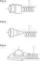
- the coiled code 6 is an electrical line that is wound in a helical shape in the extension direction as exemplarily illustrated in FIGS. 4, 5, and 6 and that can be freely expanded and contracted.
- Each coiled code 6 connects the detector connection portion 51 of the detector hub 5 and the detector 3 in an intercommunicatable and a wired manner.
- the processing unit 54 is a part having a function to execute processing of collecting the detection information obtained by the detectors 3 and transmitting the collected detection information to the detection information processing ECU 4V of the controller 4. In this example, the processing unit 54 also has a function to execute processing of determining anomaly of each detector 3.
- the processing unit 54 includes an electronic circuit mainly made of a publicly known microcomputer including a central processing unit such as a CPU, an MPU, an ASIC, or an FPGA, a ROM, a RAM, and an interface.
- the processing unit 54 is connected with the detector connection portion 51, the controller connection portion 52, and the hub connection portion 53.
- the processing unit 54 can mutually transmit and receive various electric signals to and from each component.
- the processing unit 54 functionally includes a storage unit 54a, a communication processing unit 54b, and an anomaly determination unit 54c.
- the storage unit 54a is a storage device such as a memory.
- the storage unit 54a stores therein, for example, conditions and information necessary for various kinds of processing at the processing unit 54, various computer program and applications executed by the processing unit 54, and control data.
- the storage unit 54a can temporarily store various kinds of information detected by the detectors 3. These pieces of information are read as necessary from the storage unit 54a by the processing unit 54 or the like.
- the processing unit 54 executes various computer programs stored in the storage unit 54a based on various input signals or the like so that these computer programs operate to output output signals to the components and execute various kinds of processing for achieving various kinds of functions.
- the communication processing unit 54b can execute processing of collecting the detection information obtained by the detectors 3 and collectively transmitting the collected detection information to the detection information processing ECU 4V of the controller 4. For example, the communication processing unit 54b receives the detection information obtained by the detectors 3 through the detector connection portion 51 and temporarily collectively stores the received detection information in the storage unit 54a. Then, the communication processing unit 54b collects, for each constant data frame, the detection information of the detectors 3 collectively stored in the storage unit 54a, and collectively transmits the collected detection information to the detection information processing ECU 4V through the controller connection portion 52 at a constant timing.
- the anomaly determination unit 54c can execute processing of determining anomaly of each detector 3.
- the anomaly determination unit 54c determines anomaly of the detector 3 based on, for example, an anomaly determination threshold.
- the anomaly determination threshold is a threshold set in advance to a sensing signal in accordance with the detection information of each detector 3.
- the anomaly determination unit 54c is stored in the storage unit 54a.
- the anomaly determination threshold is set to be, for example, a value larger than a physical quantity (such as a current value or a voltage value) in accordance with the sensing signal in a state in which each detector 3 is normally used. Then, the anomaly determination unit 54c determines that the detector 3 is normal when a physical quantity in accordance with the sensing signal of the detector 3 is smaller than the anomaly determination threshold.
- the anomaly determination unit 54c determines that the detector 3 is anomalous when the physical quantity in accordance with the sensing signal of the detector 3 is equal to or larger than the anomaly determination threshold. Then, for example, the communication processing unit 54b according to the present embodiment excludes the detection information of the detector 3 determined to be anomalous by the anomaly determination unit 54c from a group of pieces of information to be collectively transmitted by the detection information processing ECU 4V. Accordingly, the communication processing unit 54b does not transmit the detection information of the detector 3 determined to be anomalous by the anomaly determination unit 54c to the detection information processing ECU 4V. In this case, the communication processing unit 54b may further transmit detector anomaly information indicating that the detector 3 is anomalous to the detection information processing ECU 4V.
- the anomaly determination of the detector 3 by the anomaly determination unit 54c is not limited to the above-described method, but various kinds of well-known methods may be used.
- the on-board instruments 2 and the controller 4 are connected in an intercommunicatable manner through the first network N1.
- the first network N1 is a communication network connecting the on-board instruments 2 and the controller 4 in an intercommunicatable manner.
- the first network N1 may be an optional wired or wireless communication network.
- the first network N1 includes, for example, a power train chassis system LAN N11, a body system LAN N12, an information system LAN N13, a safety system LAN N14, and an inter-network connection unit N10.
- the power train chassis system LAN N11 is a network that mainly performs inter-instrument communication related to behavior control of the vehicle V.
- the failure diagnosis ECU 4A, the vehicle stabilization control ECU 4B, the AT ECU 4C, the light ECU 4D, the engine ECU 4E, the brake ECU 4F, and the steering ECU 4G are connected in an intercommunicatable manner.
- the AT ECU 4C, the light ECU 4D, the engine ECU 4E, the brake ECU 4F, and the steering ECU 4G are connected with the AT 2A, the light 2B, the engine 2C, the brake 2D, and the steering 2E, respectively, in an intercommunicatable manner.
- the body system LAN N12 is a network that mainly performs inter-instrument communication related to interior decorative member control of the vehicle V.
- the body ECU 4H, the door ECU 41, the meter ECU 4J, the A/C ECU 4K, the seat ECU 4L, and the keyless ECU 4M are connected in an intercommunicatable manner.
- the information system LAN N13 is a network that mainly performs inter-instrument communication of a multimedia/entertainment system of the vehicle V.
- the front seat display ECU 4N, the TV/radio tuner 4O, the stereo amplifier 4P, the back seat display ECU 4Q, and the navigation ECU 4R are connected in an intercommunicatable manner.
- the safety system LAN N14 is a network that mainly performs inter-instrument communication related to safety control of the vehicle V.
- the air bag ECU 4S, the passenger sensing ECU 4T, the seat belt ECU 4U, and the detection information processing ECU 4V are connected in an intercommunicatable manner.
- the air bag ECU 4S, the passenger sensing ECU 4T, and the seat belt ECU 4U are connected with the air bag 2O, the passenger sensor 2P, and the seat belt 2Q, respectively, in an intercommunicatable manner.
- the inter-network connection unit N10 connects the power train chassis system LAN N11, the body system LAN N12, the information system LAN N13, and the safety system LAN N14 in an intercommunicatable manner.
- the inter-network connection unit N10 has functions of a protocol conversion unit (what is called a gateway (G/W) functional component) configured to perform protocol conversion and functions of a mainline bus connecting networks.
- the first network N1 connects the power train chassis system LAN N11, the body system LAN N12, the information system LAN N13, and the safety system LAN N14 through the inter-network connection unit N10 in an intercommunicatable manner by a plurality of protocols different from each other.
- the inter-network connection unit N10 performs protocol conversion between networks of different protocols and distributes information to the networks.
- protocols used in the first network N1 include various kinds of communication protocols related to CAN communication, CAN-FD, LIN, CXPI, NFC, Giga-IR, UWB, Ethernet (registered trademark), HDMI (registered trademark), DSI, wireless transmission communication, USB3.0, Transfer Jet (registered trademark), HomePlug-GreenPHY, wireless LAN communication, sub millimeter wave communication, electrical power line communication (PLC), narrow band wireless communication, weak electric wave communication, and the like, but the protocols are not limited thereto.
- Function disposition of G/W functional components that function as the protocol conversion unit is not limited to central function disposition as illustrated in FIG.
- the central function disposition is a disposition form in which the G/W functional components in the vehicle V are disposed at one place in a concentrated manner.
- the area-distributive function disposition is a disposition form in which the G/W functional components in the vehicle V are disposed in respective optional areas in a distributed manner and cooperated with each other.
- the domain-distributive function disposition is a disposition form in which the G/W functional components in the vehicle V are disposed in respective optional domains in a distributed manner and cooperated with each other.
- the detectors 3, the corresponding detector hub 5, and the controller 4 are connected in an intercommunicatable manner through the second network N2 as illustrated in FIGS. 1 , 2 , and 3 .
- the second network N2 is a network different from the first network N1 and is a network of another system independent from the first network N1.
- the second network N2 is a detection-system dedicated communication network connecting the detectors 3, the detector hub 5, and the controller 4 in an intercommunicatable manner. More specifically, the second network N2 connects each of the detectors 3 and the detector hub 5 in an intercommunicatable manner.
- the second network N2 also connects the detector hubs 5 in an intercommunicatable manner.
- the second network N2 connects the detector hub 5 and the controller 4 in an intercommunicatable manner.
- the second network N2 may be an optional wired or wireless communication network.
- the coiled code 6 described above forms part of the second network N2.
- the second network N2 includes a network having a ring shape in which the detector hubs 5 are connected in an intercommunicatable manner.
- the second network N2 is constituted by what is called a ring topology in which the detector hubs 5, in this example, the four detector hubs 5 are nodes.
- the second network N2 connects the detector hubs 5 with the respective detectors 3 different from each other in an intercommunicatable manner.
- the second network N2 also connects each of the two detector hubs 5 on the vehicle front side among the detector hubs 5 and the detection information processing ECU 4V of the controller 4 in an intercommunicatable manner.
- the second network N2 also connects the detectors 3, the corresponding detector hub 5, and the controller 4 in an intercommunicatable manner by a single protocol, for example, Ethernet without the protocol conversion unit such as the inter-network connection unit N10 interposed therebetween.
- each of the detectors 3 and the controller 4 can perform intercommunicatable through the detector hub 5.
- the detector hub 5 collects the detection information obtained by the detectors 3 and transmits the collected detection information to the controller 4.
- the on-board system 1 tends to be required to mount various kinds of instruments and detectors 3 in accordance with recent growth of automated vehicle driving.
- the detection information of the various kinds of detectors 3 can be collected by the detector hub 5 and collectively transmitted to the controller 4, and thus it is possible to prevent communication traffic increase and achieve an appropriate communication speed.
- the detector hub 5 collects the detection information of the detectors 3 for each constant data frame and collectively transmits the collected detection information to the controller 4 at a constant timing. Accordingly, the detector hub 5 can minimize data frame vacancy and periodically and efficiently transmit the detection information to the controller 4.
- the on-board system 1 collects connection destinations of the detectors 3 by using the detector hub 5, it is possible to have improved wiring operability when various kinds of detectors 3 are mounted on the vehicle V. As a result, the on-board system 1 and the detector hub 5 can achieve appropriate communication.
- the first network N1 connects each on-board instrument 2 and the controller 4 in an intercommunicatable manner
- the second network N2 connects the detectors 3, the corresponding detector hub 5, and the controller 4 in an intercommunicatable manner.
- the first network N1 and the second network N2 are independent from each other.
- the on-board system 1 can perform transmission and reception of the detection information among each of the detectors 3, the detector hub 5, and the controller 4 separately from transmission and reception of other information. Accordingly, in communication related to the detection information, the on-board system 1 can prevent competition with other information communication, and thus can prevent communication traffic increase and achieve an appropriate communication speed.
- the on-board system 1 can reflect a result of detection by each of the detectors 3 to processing by the controller 4 and control of each component in a highly responsive manner, and thus can achieve appropriate real-time performance.
- the on-board system 1 in communication related to the detection information, can prevent mixture with other information communication, and thus can achieve appropriate reliability.
- the on-board system 1 can employ a single protocol, for example, Ethernet in the second network N2 independent from the first network N1, and thus can prevent a calculation load of protocol conversion. As described above, the on-board system 1 and the detector hub 5 can achieve appropriate communication.
- the detector hubs 5 are connected in a ring shape in an intercommunicatable manner through the second network N2.
- the on-board system 1 can achieve redundancy against breaking and the like in the second network N2 and thus achieve communication among the detector hubs 5, for example, when breaking or the like occurs between some of the detector hubs 5.
- the on-board system 1 and the detector hubs 5 can achieve more appropriate communication.
- each detector hub 5 includes the anomaly determination unit 54c.
- the detector hub 5 can collectively perform anomaly determination of the detectors 3 connected with the detector hub 5.
- the on-board system 1 can prevent increase of a calculation load on the controller 4 and distribute a calculation load to the detector hubs 5.
- the on-board system 1 can prevent anomaly detection information from being continuously transmitted to the controller 4, and thus can prevent communication traffic increase and achieve an appropriate communication speed. At this point as well, the on-board system 1 and the detector hubs 5 can achieve more appropriate communication.
- the on-board system 1 described above includes the coiled code 6 connecting each detector hub 5 with each of the detectors 3 corresponding to the detector hub 5.
- the on-board system 1 can have improved wiring operability since the coiled code 6 can be freely expanded and contracted.
- the on-board system 1 can prevent breaking from occurring between the detector hub 5 and the detector 3 when force is unintentionally applied on the coiled code 6, for example, in collision with another vehicle. At this point as well, the on-board system 1 and the detector hubs 5 can achieve more appropriate communication.
- the second network N2 connects the detectors 3, the corresponding detector hub 5, and the controller 4 in an intercommunicatable manner by a single protocol but is not limited thereto.
- the second network N2 may connect the detectors 3, the detector hub 5, and the controller 4 in an intercommunicatable manner by a plurality of protocols different from each other through the protocol conversion unit.
- the second network N2 includes a network having a ring shape in which the detector hubs 5 are connected in an intercommunicatable manner but is not limited thereto.
- the second network N2 may have what is called bus topology or star topology in place of a ring topology.
- the bus topology is network topology in which the detector hubs 5 serve as a plurality of nodes and the nodes are connected with each other through one communication line.
- the star topology is network topology in which the detector hubs 5 serve as a plurality of nodes, and one of the nodes that serves as the center is connected with the other nodes.
- each detector hub 5 includes the anomaly determination unit 54c but is not limited thereto, and the detector hub 5 may include no anomaly determination unit 54c.
- the detector connection portion 51 is connected with each detector 3 in a wired manner through the coiled code 6 but is not limited thereto.
- the detector connection portion 51 may be connected with each detector 3 in a wired manner through a normal electrical line or in a wireless manner.
- Computer programs, applications, various kinds of data, and the like described above may be updated as appropriate. For example, all or some of the computer programs, the applications, the various kinds of data, and the like described above may be downloaded as necessary.
- all or optional part of the processing function of the controller 4 and the processing unit 54 may be achieved by, for example, a CPU or the like, and a computer program interpreted and executed by the CPU or the like, or may be achieved as hardware such as wired logic.
Landscapes
- Engineering & Computer Science (AREA)
- Radar, Positioning & Navigation (AREA)
- Computer Networks & Wireless Communication (AREA)
- Remote Sensing (AREA)
- Signal Processing (AREA)
- General Physics & Mathematics (AREA)
- Physics & Mathematics (AREA)
- Health & Medical Sciences (AREA)
- Medical Informatics (AREA)
- Aviation & Aerospace Engineering (AREA)
- Game Theory and Decision Science (AREA)
- Evolutionary Computation (AREA)
- Artificial Intelligence (AREA)
- Business, Economics & Management (AREA)
- Automation & Control Theory (AREA)
- Microelectronics & Electronic Packaging (AREA)
- Mechanical Engineering (AREA)
- Small-Scale Networks (AREA)
Applications Claiming Priority (2)
| Application Number | Priority Date | Filing Date | Title |
|---|---|---|---|
| JP2017237417A JP7076997B2 (ja) | 2017-12-12 | 2017-12-12 | 車載システム、及び、検出器ハブ |
| PCT/JP2018/041513 WO2019116793A1 (ja) | 2017-12-12 | 2018-11-08 | 車載システム、及び、検出器ハブ |
Publications (3)
| Publication Number | Publication Date |
|---|---|
| EP3725596A1 EP3725596A1 (en) | 2020-10-21 |
| EP3725596A4 EP3725596A4 (en) | 2021-08-04 |
| EP3725596B1 true EP3725596B1 (en) | 2022-03-02 |
Family
ID=66819235
Family Applications (1)
| Application Number | Title | Priority Date | Filing Date |
|---|---|---|---|
| EP18888162.7A Active EP3725596B1 (en) | 2017-12-12 | 2018-11-08 | Vehicle-mounted system and detector hub |
Country Status (5)
| Country | Link |
|---|---|
| US (1) | US11027678B2 (enExample) |
| EP (1) | EP3725596B1 (enExample) |
| JP (1) | JP7076997B2 (enExample) |
| CN (1) | CN111372820B (enExample) |
| WO (1) | WO2019116793A1 (enExample) |
Families Citing this family (7)
| Publication number | Priority date | Publication date | Assignee | Title |
|---|---|---|---|---|
| US10921494B2 (en) * | 2018-01-25 | 2021-02-16 | Tdk Taiwan Corp. | Liquid optical module |
| US11597104B2 (en) * | 2019-07-31 | 2023-03-07 | X Development Llc | Mobile robot sensor configuration |
| JP7252097B2 (ja) | 2019-08-30 | 2023-04-04 | トヨタ自動車株式会社 | 車載ネットワークシステム |
| WO2021115609A1 (en) * | 2019-12-12 | 2021-06-17 | Ejzenberg Geoffrey | A situational awareness system of a cyber-physical hybrid electric autonomous or semi-autonomous off-highway dump truck for surface mining industry |
| KR20210120287A (ko) * | 2020-03-26 | 2021-10-07 | 현대자동차주식회사 | 진단 시스템 및 차량 |
| DE102020204043B4 (de) | 2020-03-27 | 2023-05-04 | Zf Friedrichshafen Ag | Bordnetz mit einem Prozessorverbund für ein Fahrzeug |
| DE102021205912B4 (de) | 2021-06-10 | 2024-08-01 | Zf Friedrichshafen Ag | Fahrzeugsystem zur Generierung von Betriebsparametern und Verfahren |
Family Cites Families (18)
| Publication number | Priority date | Publication date | Assignee | Title |
|---|---|---|---|---|
| JPS63173746A (ja) * | 1987-01-12 | 1988-07-18 | Furukawa Electric Co Ltd:The | 車両用多重伝送システム |
| US7999408B2 (en) * | 2003-05-16 | 2011-08-16 | Continental Automotive Systems, Inc. | Power and communication architecture for a vehicle |
| JP2006240603A (ja) | 2005-03-07 | 2006-09-14 | Fujikura Ltd | 車両用スライドドアの給電装置 |
| JP2007336267A (ja) | 2006-06-15 | 2007-12-27 | Toyota Motor Corp | 車載通信システム |
| WO2011074401A1 (ja) | 2009-12-15 | 2011-06-23 | 株式会社オートネットワーク技術研究所 | 通信システム、中継装置及びワイヤハーネス |
| WO2012144217A1 (ja) * | 2011-04-22 | 2012-10-26 | パナソニック株式会社 | 車両用入力装置及び車両用入力方法 |
| WO2014172369A2 (en) * | 2013-04-15 | 2014-10-23 | Flextronics Ap, Llc | Intelligent vehicle for assisting vehicle occupants and incorporating vehicle crate for blade processors |
| JP5729337B2 (ja) * | 2012-03-21 | 2015-06-03 | 株式会社デンソー | 車両用認証装置、及び車両用認証システム |
| JP5980112B2 (ja) | 2012-12-28 | 2016-08-31 | 富士通テン株式会社 | 車両情報記憶処理装置および車両情報記憶処理方法 |
| JP6362875B2 (ja) | 2014-02-27 | 2018-07-25 | クラリオン株式会社 | 車載装置、車載情報システム |
| JP2016124455A (ja) * | 2015-01-06 | 2016-07-11 | 株式会社オートネットワーク技術研究所 | 車載中継装置及び中継方法 |
| US20180048484A1 (en) * | 2015-01-30 | 2018-02-15 | Embertec Pty Ltd | Sensor hub with power manager |
| JP6417984B2 (ja) * | 2015-02-02 | 2018-11-07 | トヨタ自動車株式会社 | 車載通信システム |
| JP6588738B2 (ja) | 2015-05-21 | 2019-10-09 | 矢崎総業株式会社 | ネットワークシステム |
| JP6733293B2 (ja) | 2016-04-28 | 2020-07-29 | 株式会社デンソー | 情報処理装置 |
| WO2017204232A1 (ja) * | 2016-05-24 | 2017-11-30 | 株式会社 東芝 | 車載ゲートウェイ装置及び車載ゲートウェイシステム |
| CN111201554B (zh) * | 2017-10-17 | 2022-04-08 | 本田技研工业株式会社 | 行驶模型生成系统、行驶模型生成系统中的车辆、处理方法以及存储介质 |
| JP7398210B2 (ja) * | 2019-06-14 | 2023-12-14 | 矢崎総業株式会社 | 電気接続箱 |
-
2017
- 2017-12-12 JP JP2017237417A patent/JP7076997B2/ja active Active
-
2018
- 2018-11-08 WO PCT/JP2018/041513 patent/WO2019116793A1/ja not_active Ceased
- 2018-11-08 CN CN201880074590.9A patent/CN111372820B/zh active Active
- 2018-11-08 EP EP18888162.7A patent/EP3725596B1/en active Active
-
2020
- 2020-05-15 US US16/874,685 patent/US11027678B2/en active Active
Also Published As
| Publication number | Publication date |
|---|---|
| JP7076997B2 (ja) | 2022-05-30 |
| CN111372820B (zh) | 2022-12-06 |
| EP3725596A4 (en) | 2021-08-04 |
| WO2019116793A1 (ja) | 2019-06-20 |
| CN111372820A (zh) | 2020-07-03 |
| JP2019104338A (ja) | 2019-06-27 |
| EP3725596A1 (en) | 2020-10-21 |
| US20200269782A1 (en) | 2020-08-27 |
| US11027678B2 (en) | 2021-06-08 |
Similar Documents
| Publication | Publication Date | Title |
|---|---|---|
| EP3725596B1 (en) | Vehicle-mounted system and detector hub | |
| EP3725634B1 (en) | Vehicle-mounted system | |
| CN107972608B (zh) | 车辆对车辆通信的方法和系统 | |
| US9981616B2 (en) | Remote function control system for a vehicle having a data communications bus and related methods | |
| JP6515911B2 (ja) | 車載ネットワークシステム | |
| US9919682B2 (en) | Remote function device and associated wireless security sensor for a vehicle having a data communications bus and related methods | |
| US9656631B1 (en) | Remote function control system with wireless databus device and associated wireless security sensor for a vehicle having a data communications bus and related methods | |
| WO2018230132A1 (ja) | 分配器及び車載システム | |
| CN112937597A (zh) | 具有不同通信架构及多个网关模块的车辆 | |
| US10333207B2 (en) | Vehicle and control method of controlling the same | |
| CA2951679C (en) | Remote function control system with remote function device and associated wireless security sensor for a vehicle having a data communications bus and related methods | |
| US20240160219A1 (en) | Automated platooning system and method thereof | |
| US20200171955A1 (en) | Vehicle and method of controlling the same | |
| JP7471758B2 (ja) | 車両用通信システム | |
| JP7540353B2 (ja) | 車載装置、及び情報処理方法 | |
| US12030444B2 (en) | Selective actuation of vehicle components using two control modules | |
| CN114103836A (zh) | 多域控制车载系统以及汽车 | |
| KR20190044739A (ko) | 통신 장치, 그를 가지는 차량 및 그 제어 방법 | |
| WO2024090195A1 (ja) | 情報処理システム、通信方法、及び、移動体 | |
| CN113815547A (zh) | 车辆控制系统、设备及车辆 | |
| CA2925135A1 (en) | Remote function control system for a vehicle having a data communications bus and related methods |
Legal Events
| Date | Code | Title | Description |
|---|---|---|---|
| STAA | Information on the status of an ep patent application or granted ep patent |
Free format text: STATUS: THE INTERNATIONAL PUBLICATION HAS BEEN MADE |
|
| PUAI | Public reference made under article 153(3) epc to a published international application that has entered the european phase |
Free format text: ORIGINAL CODE: 0009012 |
|
| STAA | Information on the status of an ep patent application or granted ep patent |
Free format text: STATUS: REQUEST FOR EXAMINATION WAS MADE |
|
| 17P | Request for examination filed |
Effective date: 20200511 |
|
| AK | Designated contracting states |
Kind code of ref document: A1 Designated state(s): AL AT BE BG CH CY CZ DE DK EE ES FI FR GB GR HR HU IE IS IT LI LT LU LV MC MK MT NL NO PL PT RO RS SE SI SK SM TR |
|
| AX | Request for extension of the european patent |
Extension state: BA ME |
|
| DAV | Request for validation of the european patent (deleted) | ||
| DAX | Request for extension of the european patent (deleted) | ||
| A4 | Supplementary search report drawn up and despatched |
Effective date: 20210706 |
|
| RIC1 | Information provided on ipc code assigned before grant |
Ipc: B60R 16/023 20060101AFI20210630BHEP Ipc: G01S 13/86 20060101ALI20210630BHEP Ipc: H04L 12/40 20060101ALI20210630BHEP Ipc: H04L 12/66 20060101ALI20210630BHEP |
|
| GRAP | Despatch of communication of intention to grant a patent |
Free format text: ORIGINAL CODE: EPIDOSNIGR1 |
|
| STAA | Information on the status of an ep patent application or granted ep patent |
Free format text: STATUS: GRANT OF PATENT IS INTENDED |
|
| INTG | Intention to grant announced |
Effective date: 20211216 |
|
| GRAS | Grant fee paid |
Free format text: ORIGINAL CODE: EPIDOSNIGR3 |
|
| GRAA | (expected) grant |
Free format text: ORIGINAL CODE: 0009210 |
|
| STAA | Information on the status of an ep patent application or granted ep patent |
Free format text: STATUS: THE PATENT HAS BEEN GRANTED |
|
| AK | Designated contracting states |
Kind code of ref document: B1 Designated state(s): AL AT BE BG CH CY CZ DE DK EE ES FI FR GB GR HR HU IE IS IT LI LT LU LV MC MK MT NL NO PL PT RO RS SE SI SK SM TR |
|
| REG | Reference to a national code |
Ref country code: GB Ref legal event code: FG4D |
|
| REG | Reference to a national code |
Ref country code: CH Ref legal event code: EP Ref country code: AT Ref legal event code: REF Ref document number: 1471992 Country of ref document: AT Kind code of ref document: T Effective date: 20220315 |
|
| REG | Reference to a national code |
Ref country code: DE Ref legal event code: R096 Ref document number: 602018031808 Country of ref document: DE |
|
| REG | Reference to a national code |
Ref country code: IE Ref legal event code: FG4D |
|
| REG | Reference to a national code |
Ref country code: LT Ref legal event code: MG9D |
|
| REG | Reference to a national code |
Ref country code: NL Ref legal event code: MP Effective date: 20220302 |
|
| PG25 | Lapsed in a contracting state [announced via postgrant information from national office to epo] |
Ref country code: SE Free format text: LAPSE BECAUSE OF FAILURE TO SUBMIT A TRANSLATION OF THE DESCRIPTION OR TO PAY THE FEE WITHIN THE PRESCRIBED TIME-LIMIT Effective date: 20220302 Ref country code: RS Free format text: LAPSE BECAUSE OF FAILURE TO SUBMIT A TRANSLATION OF THE DESCRIPTION OR TO PAY THE FEE WITHIN THE PRESCRIBED TIME-LIMIT Effective date: 20220302 Ref country code: NO Free format text: LAPSE BECAUSE OF FAILURE TO SUBMIT A TRANSLATION OF THE DESCRIPTION OR TO PAY THE FEE WITHIN THE PRESCRIBED TIME-LIMIT Effective date: 20220602 Ref country code: LT Free format text: LAPSE BECAUSE OF FAILURE TO SUBMIT A TRANSLATION OF THE DESCRIPTION OR TO PAY THE FEE WITHIN THE PRESCRIBED TIME-LIMIT Effective date: 20220302 Ref country code: HR Free format text: LAPSE BECAUSE OF FAILURE TO SUBMIT A TRANSLATION OF THE DESCRIPTION OR TO PAY THE FEE WITHIN THE PRESCRIBED TIME-LIMIT Effective date: 20220302 Ref country code: ES Free format text: LAPSE BECAUSE OF FAILURE TO SUBMIT A TRANSLATION OF THE DESCRIPTION OR TO PAY THE FEE WITHIN THE PRESCRIBED TIME-LIMIT Effective date: 20220302 Ref country code: BG Free format text: LAPSE BECAUSE OF FAILURE TO SUBMIT A TRANSLATION OF THE DESCRIPTION OR TO PAY THE FEE WITHIN THE PRESCRIBED TIME-LIMIT Effective date: 20220602 |
|
| REG | Reference to a national code |
Ref country code: AT Ref legal event code: MK05 Ref document number: 1471992 Country of ref document: AT Kind code of ref document: T Effective date: 20220302 |
|
| PG25 | Lapsed in a contracting state [announced via postgrant information from national office to epo] |
Ref country code: PL Free format text: LAPSE BECAUSE OF FAILURE TO SUBMIT A TRANSLATION OF THE DESCRIPTION OR TO PAY THE FEE WITHIN THE PRESCRIBED TIME-LIMIT Effective date: 20220302 Ref country code: LV Free format text: LAPSE BECAUSE OF FAILURE TO SUBMIT A TRANSLATION OF THE DESCRIPTION OR TO PAY THE FEE WITHIN THE PRESCRIBED TIME-LIMIT Effective date: 20220302 Ref country code: GR Free format text: LAPSE BECAUSE OF FAILURE TO SUBMIT A TRANSLATION OF THE DESCRIPTION OR TO PAY THE FEE WITHIN THE PRESCRIBED TIME-LIMIT Effective date: 20220603 Ref country code: FI Free format text: LAPSE BECAUSE OF FAILURE TO SUBMIT A TRANSLATION OF THE DESCRIPTION OR TO PAY THE FEE WITHIN THE PRESCRIBED TIME-LIMIT Effective date: 20220302 |
|
| PG25 | Lapsed in a contracting state [announced via postgrant information from national office to epo] |
Ref country code: NL Free format text: LAPSE BECAUSE OF FAILURE TO SUBMIT A TRANSLATION OF THE DESCRIPTION OR TO PAY THE FEE WITHIN THE PRESCRIBED TIME-LIMIT Effective date: 20220302 |
|
| PG25 | Lapsed in a contracting state [announced via postgrant information from national office to epo] |
Ref country code: SM Free format text: LAPSE BECAUSE OF FAILURE TO SUBMIT A TRANSLATION OF THE DESCRIPTION OR TO PAY THE FEE WITHIN THE PRESCRIBED TIME-LIMIT Effective date: 20220302 Ref country code: SK Free format text: LAPSE BECAUSE OF FAILURE TO SUBMIT A TRANSLATION OF THE DESCRIPTION OR TO PAY THE FEE WITHIN THE PRESCRIBED TIME-LIMIT Effective date: 20220302 Ref country code: RO Free format text: LAPSE BECAUSE OF FAILURE TO SUBMIT A TRANSLATION OF THE DESCRIPTION OR TO PAY THE FEE WITHIN THE PRESCRIBED TIME-LIMIT Effective date: 20220302 Ref country code: PT Free format text: LAPSE BECAUSE OF FAILURE TO SUBMIT A TRANSLATION OF THE DESCRIPTION OR TO PAY THE FEE WITHIN THE PRESCRIBED TIME-LIMIT Effective date: 20220704 Ref country code: EE Free format text: LAPSE BECAUSE OF FAILURE TO SUBMIT A TRANSLATION OF THE DESCRIPTION OR TO PAY THE FEE WITHIN THE PRESCRIBED TIME-LIMIT Effective date: 20220302 Ref country code: CZ Free format text: LAPSE BECAUSE OF FAILURE TO SUBMIT A TRANSLATION OF THE DESCRIPTION OR TO PAY THE FEE WITHIN THE PRESCRIBED TIME-LIMIT Effective date: 20220302 Ref country code: AT Free format text: LAPSE BECAUSE OF FAILURE TO SUBMIT A TRANSLATION OF THE DESCRIPTION OR TO PAY THE FEE WITHIN THE PRESCRIBED TIME-LIMIT Effective date: 20220302 |
|
| PG25 | Lapsed in a contracting state [announced via postgrant information from national office to epo] |
Ref country code: IS Free format text: LAPSE BECAUSE OF FAILURE TO SUBMIT A TRANSLATION OF THE DESCRIPTION OR TO PAY THE FEE WITHIN THE PRESCRIBED TIME-LIMIT Effective date: 20220702 Ref country code: AL Free format text: LAPSE BECAUSE OF FAILURE TO SUBMIT A TRANSLATION OF THE DESCRIPTION OR TO PAY THE FEE WITHIN THE PRESCRIBED TIME-LIMIT Effective date: 20220302 |
|
| REG | Reference to a national code |
Ref country code: DE Ref legal event code: R097 Ref document number: 602018031808 Country of ref document: DE |
|
| PLBE | No opposition filed within time limit |
Free format text: ORIGINAL CODE: 0009261 |
|
| STAA | Information on the status of an ep patent application or granted ep patent |
Free format text: STATUS: NO OPPOSITION FILED WITHIN TIME LIMIT |
|
| PG25 | Lapsed in a contracting state [announced via postgrant information from national office to epo] |
Ref country code: DK Free format text: LAPSE BECAUSE OF FAILURE TO SUBMIT A TRANSLATION OF THE DESCRIPTION OR TO PAY THE FEE WITHIN THE PRESCRIBED TIME-LIMIT Effective date: 20220302 |
|
| 26N | No opposition filed |
Effective date: 20221205 |
|
| PG25 | Lapsed in a contracting state [announced via postgrant information from national office to epo] |
Ref country code: SI Free format text: LAPSE BECAUSE OF FAILURE TO SUBMIT A TRANSLATION OF THE DESCRIPTION OR TO PAY THE FEE WITHIN THE PRESCRIBED TIME-LIMIT Effective date: 20220302 |
|
| PG25 | Lapsed in a contracting state [announced via postgrant information from national office to epo] |
Ref country code: MC Free format text: LAPSE BECAUSE OF FAILURE TO SUBMIT A TRANSLATION OF THE DESCRIPTION OR TO PAY THE FEE WITHIN THE PRESCRIBED TIME-LIMIT Effective date: 20220302 |
|
| REG | Reference to a national code |
Ref country code: CH Ref legal event code: PL |
|
| GBPC | Gb: european patent ceased through non-payment of renewal fee |
Effective date: 20221108 |
|
| REG | Reference to a national code |
Ref country code: BE Ref legal event code: MM Effective date: 20221130 |
|
| PG25 | Lapsed in a contracting state [announced via postgrant information from national office to epo] |
Ref country code: LI Free format text: LAPSE BECAUSE OF NON-PAYMENT OF DUE FEES Effective date: 20221130 Ref country code: IT Free format text: LAPSE BECAUSE OF FAILURE TO SUBMIT A TRANSLATION OF THE DESCRIPTION OR TO PAY THE FEE WITHIN THE PRESCRIBED TIME-LIMIT Effective date: 20220302 Ref country code: CH Free format text: LAPSE BECAUSE OF NON-PAYMENT OF DUE FEES Effective date: 20221130 |
|
| PG25 | Lapsed in a contracting state [announced via postgrant information from national office to epo] |
Ref country code: LU Free format text: LAPSE BECAUSE OF NON-PAYMENT OF DUE FEES Effective date: 20221108 |
|
| PG25 | Lapsed in a contracting state [announced via postgrant information from national office to epo] |
Ref country code: IE Free format text: LAPSE BECAUSE OF NON-PAYMENT OF DUE FEES Effective date: 20221108 Ref country code: GB Free format text: LAPSE BECAUSE OF NON-PAYMENT OF DUE FEES Effective date: 20221108 |
|
| PG25 | Lapsed in a contracting state [announced via postgrant information from national office to epo] |
Ref country code: FR Free format text: LAPSE BECAUSE OF NON-PAYMENT OF DUE FEES Effective date: 20221130 Ref country code: BE Free format text: LAPSE BECAUSE OF NON-PAYMENT OF DUE FEES Effective date: 20221130 |
|
| PG25 | Lapsed in a contracting state [announced via postgrant information from national office to epo] |
Ref country code: CY Free format text: LAPSE BECAUSE OF FAILURE TO SUBMIT A TRANSLATION OF THE DESCRIPTION OR TO PAY THE FEE WITHIN THE PRESCRIBED TIME-LIMIT Effective date: 20220302 |
|
| PG25 | Lapsed in a contracting state [announced via postgrant information from national office to epo] |
Ref country code: MK Free format text: LAPSE BECAUSE OF FAILURE TO SUBMIT A TRANSLATION OF THE DESCRIPTION OR TO PAY THE FEE WITHIN THE PRESCRIBED TIME-LIMIT Effective date: 20220302 Ref country code: HU Free format text: LAPSE BECAUSE OF FAILURE TO SUBMIT A TRANSLATION OF THE DESCRIPTION OR TO PAY THE FEE WITHIN THE PRESCRIBED TIME-LIMIT; INVALID AB INITIO Effective date: 20181108 |
|
| PG25 | Lapsed in a contracting state [announced via postgrant information from national office to epo] |
Ref country code: TR Free format text: LAPSE BECAUSE OF FAILURE TO SUBMIT A TRANSLATION OF THE DESCRIPTION OR TO PAY THE FEE WITHIN THE PRESCRIBED TIME-LIMIT Effective date: 20220302 |
|
| PG25 | Lapsed in a contracting state [announced via postgrant information from national office to epo] |
Ref country code: MT Free format text: LAPSE BECAUSE OF FAILURE TO SUBMIT A TRANSLATION OF THE DESCRIPTION OR TO PAY THE FEE WITHIN THE PRESCRIBED TIME-LIMIT Effective date: 20220302 |
|
| PGFP | Annual fee paid to national office [announced via postgrant information from national office to epo] |
Ref country code: DE Payment date: 20241001 Year of fee payment: 7 |