WO2019116587A1 - ハイブリッド車両の触媒暖機制御方法、及びハイブリッド車両の触媒暖機制御装置 - Google Patents
ハイブリッド車両の触媒暖機制御方法、及びハイブリッド車両の触媒暖機制御装置 Download PDFInfo
- Publication number
- WO2019116587A1 WO2019116587A1 PCT/JP2017/045221 JP2017045221W WO2019116587A1 WO 2019116587 A1 WO2019116587 A1 WO 2019116587A1 JP 2017045221 W JP2017045221 W JP 2017045221W WO 2019116587 A1 WO2019116587 A1 WO 2019116587A1
- Authority
- WO
- WIPO (PCT)
- Prior art keywords
- rotational speed
- warm
- target
- catalyst
- engine
- Prior art date
Links
Images


Classifications
-
- B—PERFORMING OPERATIONS; TRANSPORTING
- B60—VEHICLES IN GENERAL
- B60K—ARRANGEMENT OR MOUNTING OF PROPULSION UNITS OR OF TRANSMISSIONS IN VEHICLES; ARRANGEMENT OR MOUNTING OF PLURAL DIVERSE PRIME-MOVERS IN VEHICLES; AUXILIARY DRIVES FOR VEHICLES; INSTRUMENTATION OR DASHBOARDS FOR VEHICLES; ARRANGEMENTS IN CONNECTION WITH COOLING, AIR INTAKE, GAS EXHAUST OR FUEL SUPPLY OF PROPULSION UNITS IN VEHICLES
- B60K6/00—Arrangement or mounting of plural diverse prime-movers for mutual or common propulsion, e.g. hybrid propulsion systems comprising electric motors and internal combustion engines ; Control systems therefor, i.e. systems controlling two or more prime movers, or controlling one of these prime movers and any of the transmission, drive or drive units Informative references: mechanical gearings with secondary electric drive F16H3/72; arrangements for handling mechanical energy structurally associated with the dynamo-electric machine H02K7/00; machines comprising structurally interrelated motor and generator parts H02K51/00; dynamo-electric machines not otherwise provided for in H02K see H02K99/00
- B60K6/20—Arrangement or mounting of plural diverse prime-movers for mutual or common propulsion, e.g. hybrid propulsion systems comprising electric motors and internal combustion engines ; Control systems therefor, i.e. systems controlling two or more prime movers, or controlling one of these prime movers and any of the transmission, drive or drive units Informative references: mechanical gearings with secondary electric drive F16H3/72; arrangements for handling mechanical energy structurally associated with the dynamo-electric machine H02K7/00; machines comprising structurally interrelated motor and generator parts H02K51/00; dynamo-electric machines not otherwise provided for in H02K see H02K99/00 the prime-movers consisting of electric motors and internal combustion engines, e.g. HEVs
- B60K6/42—Arrangement or mounting of plural diverse prime-movers for mutual or common propulsion, e.g. hybrid propulsion systems comprising electric motors and internal combustion engines ; Control systems therefor, i.e. systems controlling two or more prime movers, or controlling one of these prime movers and any of the transmission, drive or drive units Informative references: mechanical gearings with secondary electric drive F16H3/72; arrangements for handling mechanical energy structurally associated with the dynamo-electric machine H02K7/00; machines comprising structurally interrelated motor and generator parts H02K51/00; dynamo-electric machines not otherwise provided for in H02K see H02K99/00 the prime-movers consisting of electric motors and internal combustion engines, e.g. HEVs characterised by the architecture of the hybrid electric vehicle
- B60K6/46—Series type
-
- F—MECHANICAL ENGINEERING; LIGHTING; HEATING; WEAPONS; BLASTING
- F01—MACHINES OR ENGINES IN GENERAL; ENGINE PLANTS IN GENERAL; STEAM ENGINES
- F01N—GAS-FLOW SILENCERS OR EXHAUST APPARATUS FOR MACHINES OR ENGINES IN GENERAL; GAS-FLOW SILENCERS OR EXHAUST APPARATUS FOR INTERNAL COMBUSTION ENGINES
- F01N3/00—Exhaust or silencing apparatus having means for purifying, rendering innocuous, or otherwise treating exhaust
- F01N3/08—Exhaust or silencing apparatus having means for purifying, rendering innocuous, or otherwise treating exhaust for rendering innocuous
- F01N3/10—Exhaust or silencing apparatus having means for purifying, rendering innocuous, or otherwise treating exhaust for rendering innocuous by thermal or catalytic conversion of noxious components of exhaust
- F01N3/18—Exhaust or silencing apparatus having means for purifying, rendering innocuous, or otherwise treating exhaust for rendering innocuous by thermal or catalytic conversion of noxious components of exhaust characterised by methods of operation; Control
- F01N3/20—Exhaust or silencing apparatus having means for purifying, rendering innocuous, or otherwise treating exhaust for rendering innocuous by thermal or catalytic conversion of noxious components of exhaust characterised by methods of operation; Control specially adapted for catalytic conversion ; Methods of operation or control of catalytic converters
- F01N3/2006—Periodically heating or cooling catalytic reactors, e.g. at cold starting or overheating
-
- B—PERFORMING OPERATIONS; TRANSPORTING
- B60—VEHICLES IN GENERAL
- B60W—CONJOINT CONTROL OF VEHICLE SUB-UNITS OF DIFFERENT TYPE OR DIFFERENT FUNCTION; CONTROL SYSTEMS SPECIALLY ADAPTED FOR HYBRID VEHICLES; ROAD VEHICLE DRIVE CONTROL SYSTEMS FOR PURPOSES NOT RELATED TO THE CONTROL OF A PARTICULAR SUB-UNIT
- B60W10/00—Conjoint control of vehicle sub-units of different type or different function
- B60W10/04—Conjoint control of vehicle sub-units of different type or different function including control of propulsion units
- B60W10/08—Conjoint control of vehicle sub-units of different type or different function including control of propulsion units including control of electric propulsion units, e.g. motors or generators
-
- B—PERFORMING OPERATIONS; TRANSPORTING
- B60—VEHICLES IN GENERAL
- B60W—CONJOINT CONTROL OF VEHICLE SUB-UNITS OF DIFFERENT TYPE OR DIFFERENT FUNCTION; CONTROL SYSTEMS SPECIALLY ADAPTED FOR HYBRID VEHICLES; ROAD VEHICLE DRIVE CONTROL SYSTEMS FOR PURPOSES NOT RELATED TO THE CONTROL OF A PARTICULAR SUB-UNIT
- B60W10/00—Conjoint control of vehicle sub-units of different type or different function
- B60W10/04—Conjoint control of vehicle sub-units of different type or different function including control of propulsion units
- B60W10/06—Conjoint control of vehicle sub-units of different type or different function including control of propulsion units including control of combustion engines
-
- B—PERFORMING OPERATIONS; TRANSPORTING
- B60—VEHICLES IN GENERAL
- B60W—CONJOINT CONTROL OF VEHICLE SUB-UNITS OF DIFFERENT TYPE OR DIFFERENT FUNCTION; CONTROL SYSTEMS SPECIALLY ADAPTED FOR HYBRID VEHICLES; ROAD VEHICLE DRIVE CONTROL SYSTEMS FOR PURPOSES NOT RELATED TO THE CONTROL OF A PARTICULAR SUB-UNIT
- B60W10/00—Conjoint control of vehicle sub-units of different type or different function
- B60W10/24—Conjoint control of vehicle sub-units of different type or different function including control of energy storage means
- B60W10/26—Conjoint control of vehicle sub-units of different type or different function including control of energy storage means for electrical energy, e.g. batteries or capacitors
-
- B—PERFORMING OPERATIONS; TRANSPORTING
- B60—VEHICLES IN GENERAL
- B60W—CONJOINT CONTROL OF VEHICLE SUB-UNITS OF DIFFERENT TYPE OR DIFFERENT FUNCTION; CONTROL SYSTEMS SPECIALLY ADAPTED FOR HYBRID VEHICLES; ROAD VEHICLE DRIVE CONTROL SYSTEMS FOR PURPOSES NOT RELATED TO THE CONTROL OF A PARTICULAR SUB-UNIT
- B60W20/00—Control systems specially adapted for hybrid vehicles
- B60W20/10—Controlling the power contribution of each of the prime movers to meet required power demand
- B60W20/13—Controlling the power contribution of each of the prime movers to meet required power demand in order to stay within battery power input or output limits; in order to prevent overcharging or battery depletion
-
- B—PERFORMING OPERATIONS; TRANSPORTING
- B60—VEHICLES IN GENERAL
- B60W—CONJOINT CONTROL OF VEHICLE SUB-UNITS OF DIFFERENT TYPE OR DIFFERENT FUNCTION; CONTROL SYSTEMS SPECIALLY ADAPTED FOR HYBRID VEHICLES; ROAD VEHICLE DRIVE CONTROL SYSTEMS FOR PURPOSES NOT RELATED TO THE CONTROL OF A PARTICULAR SUB-UNIT
- B60W20/00—Control systems specially adapted for hybrid vehicles
- B60W20/10—Controlling the power contribution of each of the prime movers to meet required power demand
- B60W20/15—Control strategies specially adapted for achieving a particular effect
- B60W20/16—Control strategies specially adapted for achieving a particular effect for reducing engine exhaust emissions
-
- B—PERFORMING OPERATIONS; TRANSPORTING
- B60—VEHICLES IN GENERAL
- B60W—CONJOINT CONTROL OF VEHICLE SUB-UNITS OF DIFFERENT TYPE OR DIFFERENT FUNCTION; CONTROL SYSTEMS SPECIALLY ADAPTED FOR HYBRID VEHICLES; ROAD VEHICLE DRIVE CONTROL SYSTEMS FOR PURPOSES NOT RELATED TO THE CONTROL OF A PARTICULAR SUB-UNIT
- B60W20/00—Control systems specially adapted for hybrid vehicles
- B60W20/10—Controlling the power contribution of each of the prime movers to meet required power demand
- B60W20/15—Control strategies specially adapted for achieving a particular effect
- B60W20/17—Control strategies specially adapted for achieving a particular effect for noise reduction
-
- F—MECHANICAL ENGINEERING; LIGHTING; HEATING; WEAPONS; BLASTING
- F02—COMBUSTION ENGINES; HOT-GAS OR COMBUSTION-PRODUCT ENGINE PLANTS
- F02D—CONTROLLING COMBUSTION ENGINES
- F02D29/00—Controlling engines, such controlling being peculiar to the devices driven thereby, the devices being other than parts or accessories essential to engine operation, e.g. controlling of engines by signals external thereto
- F02D29/06—Controlling engines, such controlling being peculiar to the devices driven thereby, the devices being other than parts or accessories essential to engine operation, e.g. controlling of engines by signals external thereto peculiar to engines driving electric generators
-
- F—MECHANICAL ENGINEERING; LIGHTING; HEATING; WEAPONS; BLASTING
- F02—COMBUSTION ENGINES; HOT-GAS OR COMBUSTION-PRODUCT ENGINE PLANTS
- F02D—CONTROLLING COMBUSTION ENGINES
- F02D43/00—Conjoint electrical control of two or more functions, e.g. ignition, fuel-air mixture, recirculation, supercharging or exhaust-gas treatment
-
- F—MECHANICAL ENGINEERING; LIGHTING; HEATING; WEAPONS; BLASTING
- F02—COMBUSTION ENGINES; HOT-GAS OR COMBUSTION-PRODUCT ENGINE PLANTS
- F02D—CONTROLLING COMBUSTION ENGINES
- F02D45/00—Electrical control not provided for in groups F02D41/00 - F02D43/00
-
- B—PERFORMING OPERATIONS; TRANSPORTING
- B60—VEHICLES IN GENERAL
- B60W—CONJOINT CONTROL OF VEHICLE SUB-UNITS OF DIFFERENT TYPE OR DIFFERENT FUNCTION; CONTROL SYSTEMS SPECIALLY ADAPTED FOR HYBRID VEHICLES; ROAD VEHICLE DRIVE CONTROL SYSTEMS FOR PURPOSES NOT RELATED TO THE CONTROL OF A PARTICULAR SUB-UNIT
- B60W2510/00—Input parameters relating to a particular sub-units
- B60W2510/24—Energy storage means
- B60W2510/242—Energy storage means for electrical energy
- B60W2510/244—Charge state
-
- B—PERFORMING OPERATIONS; TRANSPORTING
- B60—VEHICLES IN GENERAL
- B60W—CONJOINT CONTROL OF VEHICLE SUB-UNITS OF DIFFERENT TYPE OR DIFFERENT FUNCTION; CONTROL SYSTEMS SPECIALLY ADAPTED FOR HYBRID VEHICLES; ROAD VEHICLE DRIVE CONTROL SYSTEMS FOR PURPOSES NOT RELATED TO THE CONTROL OF A PARTICULAR SUB-UNIT
- B60W2530/00—Input parameters relating to vehicle conditions or values, not covered by groups B60W2510/00 or B60W2520/00
- B60W2530/12—Catalyst or filter state
-
- B—PERFORMING OPERATIONS; TRANSPORTING
- B60—VEHICLES IN GENERAL
- B60W—CONJOINT CONTROL OF VEHICLE SUB-UNITS OF DIFFERENT TYPE OR DIFFERENT FUNCTION; CONTROL SYSTEMS SPECIALLY ADAPTED FOR HYBRID VEHICLES; ROAD VEHICLE DRIVE CONTROL SYSTEMS FOR PURPOSES NOT RELATED TO THE CONTROL OF A PARTICULAR SUB-UNIT
- B60W2530/00—Input parameters relating to vehicle conditions or values, not covered by groups B60W2510/00 or B60W2520/00
- B60W2530/13—Mileage
-
- B—PERFORMING OPERATIONS; TRANSPORTING
- B60—VEHICLES IN GENERAL
- B60W—CONJOINT CONTROL OF VEHICLE SUB-UNITS OF DIFFERENT TYPE OR DIFFERENT FUNCTION; CONTROL SYSTEMS SPECIALLY ADAPTED FOR HYBRID VEHICLES; ROAD VEHICLE DRIVE CONTROL SYSTEMS FOR PURPOSES NOT RELATED TO THE CONTROL OF A PARTICULAR SUB-UNIT
- B60W2710/00—Output or target parameters relating to a particular sub-units
- B60W2710/06—Combustion engines, Gas turbines
- B60W2710/0644—Engine speed
-
- B—PERFORMING OPERATIONS; TRANSPORTING
- B60—VEHICLES IN GENERAL
- B60W—CONJOINT CONTROL OF VEHICLE SUB-UNITS OF DIFFERENT TYPE OR DIFFERENT FUNCTION; CONTROL SYSTEMS SPECIALLY ADAPTED FOR HYBRID VEHICLES; ROAD VEHICLE DRIVE CONTROL SYSTEMS FOR PURPOSES NOT RELATED TO THE CONTROL OF A PARTICULAR SUB-UNIT
- B60W2710/00—Output or target parameters relating to a particular sub-units
- B60W2710/06—Combustion engines, Gas turbines
- B60W2710/0666—Engine torque
-
- B—PERFORMING OPERATIONS; TRANSPORTING
- B60—VEHICLES IN GENERAL
- B60W—CONJOINT CONTROL OF VEHICLE SUB-UNITS OF DIFFERENT TYPE OR DIFFERENT FUNCTION; CONTROL SYSTEMS SPECIALLY ADAPTED FOR HYBRID VEHICLES; ROAD VEHICLE DRIVE CONTROL SYSTEMS FOR PURPOSES NOT RELATED TO THE CONTROL OF A PARTICULAR SUB-UNIT
- B60W2720/00—Output or target parameters relating to overall vehicle dynamics
- B60W2720/10—Longitudinal speed
-
- B—PERFORMING OPERATIONS; TRANSPORTING
- B60—VEHICLES IN GENERAL
- B60Y—INDEXING SCHEME RELATING TO ASPECTS CROSS-CUTTING VEHICLE TECHNOLOGY
- B60Y2200/00—Type of vehicle
- B60Y2200/90—Vehicles comprising electric prime movers
- B60Y2200/92—Hybrid vehicles
-
- F—MECHANICAL ENGINEERING; LIGHTING; HEATING; WEAPONS; BLASTING
- F01—MACHINES OR ENGINES IN GENERAL; ENGINE PLANTS IN GENERAL; STEAM ENGINES
- F01N—GAS-FLOW SILENCERS OR EXHAUST APPARATUS FOR MACHINES OR ENGINES IN GENERAL; GAS-FLOW SILENCERS OR EXHAUST APPARATUS FOR INTERNAL COMBUSTION ENGINES
- F01N2900/00—Details of electrical control or of the monitoring of the exhaust gas treating apparatus
- F01N2900/06—Parameters used for exhaust control or diagnosing
- F01N2900/10—Parameters used for exhaust control or diagnosing said parameters being related to the vehicle or its components
- F01N2900/104—Battery status
-
- F—MECHANICAL ENGINEERING; LIGHTING; HEATING; WEAPONS; BLASTING
- F01—MACHINES OR ENGINES IN GENERAL; ENGINE PLANTS IN GENERAL; STEAM ENGINES
- F01N—GAS-FLOW SILENCERS OR EXHAUST APPARATUS FOR MACHINES OR ENGINES IN GENERAL; GAS-FLOW SILENCERS OR EXHAUST APPARATUS FOR INTERNAL COMBUSTION ENGINES
- F01N2900/00—Details of electrical control or of the monitoring of the exhaust gas treating apparatus
- F01N2900/06—Parameters used for exhaust control or diagnosing
- F01N2900/16—Parameters used for exhaust control or diagnosing said parameters being related to the exhaust apparatus, e.g. particulate filter or catalyst
- F01N2900/1626—Catalyst activation temperature
-
- Y—GENERAL TAGGING OF NEW TECHNOLOGICAL DEVELOPMENTS; GENERAL TAGGING OF CROSS-SECTIONAL TECHNOLOGIES SPANNING OVER SEVERAL SECTIONS OF THE IPC; TECHNICAL SUBJECTS COVERED BY FORMER USPC CROSS-REFERENCE ART COLLECTIONS [XRACs] AND DIGESTS
- Y02—TECHNOLOGIES OR APPLICATIONS FOR MITIGATION OR ADAPTATION AGAINST CLIMATE CHANGE
- Y02A—TECHNOLOGIES FOR ADAPTATION TO CLIMATE CHANGE
- Y02A50/00—TECHNOLOGIES FOR ADAPTATION TO CLIMATE CHANGE in human health protection, e.g. against extreme weather
- Y02A50/20—Air quality improvement or preservation, e.g. vehicle emission control or emission reduction by using catalytic converters
Definitions
- the present invention relates to a catalyst warm-up control method for a hybrid vehicle and a catalyst warm-up control device for a hybrid vehicle.
- the optimization torque and the optimization rotational speed at which the fuel efficiency of the engine is maximized are set. Therefore, the battery is charged by the optimized power generation generated based on the optimized rotation speed and the optimized torque, and the catalyst is warmed up by the exhaust gas discharged according to the optimized rotation speed.
- the upper limit generated power of the engine is limited based on the SOC (State Of Charge: charge rate) of the battery, and the above-mentioned optimized generated power exceeds the upper limit generated power, the target engine speed of the engine And the target torque is limited and the generated power is suppressed to the upper limit generated power.
- SOC State Of Charge: charge rate
- an object of the present invention is to reliably warm up a catalyst regardless of the SOC of a battery in a hybrid vehicle.
- One aspect of the present invention is a method for controlling catalyst warm-up of a hybrid vehicle, in which the battery supplies electric power to the electric motor, the battery is charged by the power generation engine, and the exhaust gas discharged from the engine is treated with a catalyst.
- the catalyst warm-up control method controls the target engine speed and the target torque of the engine based on the charging rate of the battery when the temperature of the catalyst becomes lower than the warm-up required temperature for activating the catalyst.
- the target rotational speed is lower than the lower limit rotational speed capable of heating the catalyst to the warm-up required temperature
- the target rotational speed is controlled to the warm-up required rotational speed equal to or higher than the lower limit rotational speed.
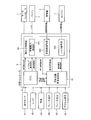
- FIG. 1 is a block diagram showing the configuration of a hybrid vehicle to which the present embodiment is applied.
- FIG. 2 is a control block diagram of the catalyst warm-up control device of the hybrid vehicle of the present embodiment.
- FIG. 3 is a diagram showing the relationship between the vehicle speed, the lower limit rotational speed for making a warm-up request for the catalyst, the required warm-up rotational speed, and the vehicle speed.
- FIG. 4 is a diagram showing a relationship between an operating point relating to a target engine speed and a target torque of an engine in a hybrid vehicle and an upper limit generated power determined by the SOC.
- FIG. 5 is a diagram showing a relationship between an operating point relating to a target engine speed and a target torque of the engine at the time of warm-up control in the hybrid vehicle and an upper limit generated power determined by the SOC.
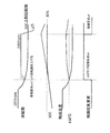
- FIG. 6 is a time chart of the actual engine speed, the temperature of the catalyst, and the catalyst warm-up request signal when warm-up control is performed in the hybrid vehicle.
- FIG. 1 is a block diagram showing the configuration of a hybrid vehicle to which the present embodiment is applied.
- a hybrid vehicle to which the present embodiment is applied includes an engine 1, a generator 2, a battery 3, an electric motor 4, wheels 6 (driving wheels), and a motor controller 7 for controlling the electric motor 4. .
- the wheels 1 are not driven by the engine 1 and the wheels 6 are driven by the power supplied from the battery 3, and the engine 1, the battery 3 and the wheels 6 are connected in series (series connection). It is called a series hybrid car.
- the engine 1 is mechanically coupled to the generator 2 via a reduction gear (not shown).
- the generator 2 is connected to the battery 3 so as to be capable of transmitting and receiving power. Power transmission and reception are connected between the battery 3 and the motor controller 7 and between the motor controller 7 and the electric motor 4.
- the driving force of the engine 1 is transmitted to the generator 2, and the generator 2 generates electric power by the driving force of the engine 1.
- the power generated by the generator 2 is charged to the battery 3.
- the power charged in the battery 3 is transmitted to the electric motor 4 via the motor controller 7, and the electric motor 4 is driven by the power supplied from the battery 3.
- the wheel 6 is rotated by the driving force of the electric motor 4 via the gear 5 to drive the hybrid vehicle. Further, when decelerating, the electric motor 4 applies regenerative braking force to the wheel 6 to generate regenerative electric power, and the regenerative electric power is charged to the battery 3 via the motor controller 7.
- the hybrid vehicle includes a mode switch 81 for selecting a plurality of traveling modes alternatively, a select lever 82 operated by a driver when selecting a range of the automatic transmission, and a vehicle speed sensor 83 for detecting the speed of the vehicle.
- a vehicle controller 9 catalyst warm-up control device
- the vehicle controller 9 is electrically connected to each of the mode switch 81, the select lever 82, the vehicle speed sensor 83, the brake hydraulic pressure sensor 84, the brake negative pressure sensor 85, and the accelerator position sensor 86.
- Vehicle controller 9 receives a signal indicating the selected traveling mode from mode switch 81, receives a signal indicating the selected range from select lever 82, and receives a signal indicating the speed of the hybrid vehicle from vehicle speed sensor 83.
- a signal indicating the brake hydraulic pressure is received from the brake hydraulic pressure sensor 84, a signal indicating the brake negative pressure is received from the brake negative pressure sensor 85, and a signal indicating the accelerator opening is received from the accelerator position sensor 86.
- the traveling modes selectable by the mode switch 81 the normal mode in which the regenerative braking force by the electric motor 4 is relatively small, the eco mode in which the regenerative braking force is larger than in the normal mode, and the engine 1 by the operation of the mode switch 81 And a charge mode for generating power using the engine 1 according to the operation of the mode switch 81.
- the range selectable by the select lever 82 includes a drive range, a reverse range, a neutral range, a parking range, and the like.
- the vehicle controller 9 is connected to the engine 1, the generator 2, the battery 3, and the motor controller 7.
- the vehicle controller 9 transmits an engine torque command value (hereinafter referred to as a torque command value) to the engine 1, transmits a rotation speed command value to the generator 2, and transmits a motor torque command value to the motor controller 7.
- the vehicle controller 9 can be realized by, for example, a general-purpose microcomputer including a CPU (central processing unit), a memory, and an input / output unit.
- a computer program for causing a microcomputer to function as a vehicle controller 9 is installed and executed in the microcomputer.
- the vehicle controller 9 can be realized by software, but individual hardware may be configured for each unit which also performs information processing in the vehicle controller 9.
- the motor controller 7 can likewise be configured as software or hardware.
- the vehicle controller 9 (ECU 91 described later) generates electric power by the engine 1 and the generator 2 to charge the battery 3 when the SOC of the battery 3 becomes less than a predetermined lower limit value, and limits or stops the power generation when the predetermined upper limit value is reached.
- the vehicle controller 9 supplies surplus regenerative power to the generator 2 and rotates the engine 1 by the generator 2 to regenerate surplus power. Consume power.
- the vehicle controller 9 restores the brake negative pressure by supplying power to the generator 2 to rotate the engine 1 even when the brake negative pressure becomes smaller than a predetermined value.
- FIG. 2 is a control block diagram of the catalyst warm-up control device of the hybrid vehicle of the present embodiment.
- the vehicle controller 9 includes an ECU 91 (engine control unit) (which may be configured separately from the vehicle controller 9), a catalyst warmup request computation unit 92 (catalyst warmup controller) and an operating point control.
- a section 93 (catalyst warm-up control device) is provided.
- the ECU 91 controls the entire hybrid vehicle based on the traveling mode, the range, the signals input from the various sensors, and the computer program.
- the ECU 91 transmits a command signal (power generation request signal or motoring request signal) to the operating point control unit 93 based on the traveling state (including the state of SOC) of the hybrid vehicle, and may stop transmission of the command signal. it can.
- the power generation request signal is a signal that requests power generation using the engine 1 and the generator 2.
- the ECU 91 calculates the upper limit generated power that can be generated by the engine 1 and the generator 2 based on the magnitude of the SOC input from the battery 3 and transmits it to the operating point control unit 93 .
- the motoring request signal is transmitted when the surplus regenerative power is consumed or when the brake negative pressure is restored.
- the ECU 91 estimates the temperature of the catalyst attached to the exhaust system of the engine 1 based on the traveling state of the hybrid vehicle, and transmits information of the catalyst temperature estimated value to the catalyst warmup request computation unit 92.
- the temperature of the catalyst may not be estimated but may be actually measured by a temperature sensor or the like.
- the catalyst warmup request computation unit 92 determines whether to perform catalyst warmup control based on the catalyst temperature estimated value (or the measured value by the temperature sensor) input from the ECU 91, and the catalyst temperature estimated value is warmed up. When it becomes lower than the machine required temperature, the catalyst warm up request signal (catalyst warm up request flag) is sent, and then the catalyst temperature estimated value is set temperature higher than the warm up required temperature or the warm up required temperature by a predetermined temperature (for example 30 degrees) When it is reached, the catalyst warmup request signal is stopped. Alternatively, the catalyst warmup request operation unit 92 stops the transmission of the catalyst warmup request signal when a predetermined time (for example, 15 seconds) elapses after the catalyst warmup request signal is transmitted.
- a predetermined time for example, 15 seconds
- the catalyst warmup request operation unit 92 transmits a catalyst warmup request signal to the operating point control unit 93
- the catalyst warmup request operation unit 92 receives the information of the first target rotational speed described later from the operating point control unit 93.
- the information on the second target rotational speed that has been input is sent back to the operating point control unit 93.
- the second target rotation number is the lower limit rotation number or a rotation number higher than this when the first target rotation number is lower than the lower limit rotation number capable of being heated to the warm-up required temperature necessary for activating the catalyst. Is set to the required warm-up request rotational speed. If the second target rotation speed is equal to or higher than the lower limit rotation speed, the second target rotation speed is set to the same value as the first target rotation speed.
- the catalyst warm-up request calculation unit 92 receives the information of the vehicle speed and sets the warm-up required temperature and the warm-up request rotational speed based on the information of the vehicle speed. Details will be described later (FIG. 3).
- Operating point control unit 93 calculates power generation control unit 931 that calculates (controls) the target rotation speed and the target torque based on the SOC of battery 3, and rotation speed adjustment unit 932 that transmits the rotation command value based on the target rotation speed. And a torque adjustment unit 933 that transmits a torque command value based on the target torque.
- the generated power control unit 931 controls the target rotational speed (first target rotational speed) to a rotational speed (second target rotational speed) related to the warm-up required rotational speed.
- the generated power control unit 931 operates the engine 1 and the generator 2 when receiving the power generation request signal or the catalyst warm-up request signal, and when the reception of the power generation request signal or the catalyst warm-up request signal ends, the engine 1 and the generator 2 Stop it.
- the generated power control unit 931 operates the generator 2 without operating the engine 1 when the motoring request signal is received, and stops the generator 2 when the reception of the motoring request signal ends.
- the generated power control unit 931 When receiving the power generation request signal, the generated power control unit 931 generates a rotation speed command value via the rotation speed adjustment unit 932 and transmits it to the generator 2 and generates a torque command value via the torque adjustment unit 933. Send to engine 1 The rotation speed command value and the torque command value are generated based on the upper limit generated power determined based on the SOC of the battery 3.
- the generated power control unit 931 compares the optimized generated power determined by the product of the optimized rotation speed and the optimized torque with the upper limit generated power transmitted from the ECU 91, and the optimized generated power is higher than the upper limit generated power. If the speed is also low, the target rotation speed is controlled to the optimization rotation speed, and the target torque is controlled to the optimization torque, and power generation using the engine 1 and the generator 2 is performed.
- the upper limit generated power decreases as the SOC increases. Therefore, when the upper limit generated power is smaller than the optimized generated power, the generated power control unit 931 calculates the target rotation speed and the target torque so as to be equal to the upper limit generated power. At this time, the target rotational speed and the target torque are calculated such that noise such as rattle noise (and noise generated from the generator 2) does not occur as described later.
- the generated power control unit 931 When the generated power control unit 931 receives the information on the warm-up request rotational speed from the catalyst warm-up request calculation unit 92, it calculates the target rotational speed and the target torque in the same manner as described above, and the target rotational speed (first target rotational speed) Is output to the catalyst warmup request operation unit 92. Then, based on the second target rotation number returned from the catalyst warm-up request calculation unit 92, a rotation number command value is generated and transmitted via the rotation number adjustment unit 932. At this time, the target torque is adjusted so that abnormal noise does not occur in the engine 1 as described above, and a torque command value is generated based on the adjusted target torque. The details of the calculation of the target rotational speed and the target torque will be described later (FIG. 4, FIG. 5).
- FIG. 3 is a diagram showing the relationship between the vehicle speed, the lower limit rotational speed for making a warm-up request for the catalyst, the required warm-up rotational speed, and the vehicle speed.
- the catalyst (for example, a three-way catalyst) purifies the exhaust gas discharged during operation of the engine 1.
- the catalyst exhibits purification performance by being warmed up, but it becomes possible to purify the exhaust gas with high efficiency particularly when the temperature becomes a predetermined activation temperature or higher.
- the target rotational speed of the engine 1 is generally controlled to be low, and the amount of exhaust gas is also reduced. Therefore, even if the temperature of the catalyst is below the activation temperature, it is acceptable. Therefore, in the present embodiment, the warm-up required temperature for activating the catalyst is determined based on the vehicle speed.
- the temperature required to activate the catalyst is 480 ° C. or less when the vehicle speed is 15 kph or less, and is approximately 630 ° C. when the vehicle speed is 18 kph or more.
- the catalyst temperature monotonously increases with an increase in the actual rotation speed in the range from 1200 rpm to 3050 rpm of the actual rotation speed of the engine 1 (supply amount of exhaust gas).
- the inventors of the present invention have obtained the finding that the temperature of the catalyst is heated to 549 ° C., which exceeds 480 ° C., when the rotation speed is 1200 rpm. Further, the inventor of the present invention has found that, when the actual rotation speed is 2000 rpm, the temperature of the catalyst is heated to 660 ° C. or higher, which exceeds 630 ° C., which is the active temperature.
- the lower limit rotation speed when the vehicle speed is 18 kph or more is 2000 rpm
- the lower limit rotation speed when the vehicle speed is 15 kph or less is set as 1200 rpm.
- the warm-up required rotational speed in the case of 18 kph or more is 2000 rpm.
- the warm-up required rotational speed when the vehicle speed is 15 kph or less is set to 1400 rpm. This is in consideration of the instability of the purification performance in the low temperature range (low speed range of the vehicle speed) of the catalyst.
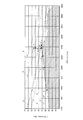
- FIG. 4 is a diagram showing a relationship between an operating point related to the target rotation speed and the target torque of the engine 1 in the hybrid vehicle and the upper limit generated power determined by the SOC.
- FIG. 5 is a diagram showing a relationship between an operating point relating to the target rotational speed and the target torque of the engine 1 at the time of warm-up control in the hybrid vehicle and the upper limit generated power determined by the SOC.
- FIGS. 4 and 5 show characteristic coordinates in which the horizontal axis represents the target rotational speed and the vertical axis represents the target torque.
- the target generated power output from the engine 1 and the generator 2 can be obtained by the product of the target rotational speed and the target torque. Therefore, the upper limit generated power can be represented by a curve (hyperbola) of A to F indicated by an alternate long and short dash line in FIG. 4 and FIG.
- a to F are determined based on the SOC of the battery 3. The SOC of the battery 3 is the lowest and the upper limit generated power is the highest in A, and the SOC increases as B, C, and D shift. At the same time, the upper limit generated power decreases, and in F, the SOC of the battery 3 is the highest and the upper limit generated power is the lowest.
- the star marks shown in FIG. 4 and FIG. 5 represent, at the characteristic coordinates, the operating point a of the optimized rotational speed and the optimized torque at which the fuel efficiency of the engine 1 becomes maximum, and this product becomes the optimized power generation .
- the generated power control unit 931 when receiving the power generation request signal or the catalyst warm-up request signal, the generated power control unit 931 generates power using the engine 1 and the generator 2 at the operating point a (optimized rotational speed and optimized torque). .
- B to F pass a position lower than the operating point a in the target rotational speed direction and the target torque direction, and indicate that the upper limit generated power is lower than the optimized generated power.
- the generated power control unit 931 controls the target rotational speed and the target torque (operating point) such that the target generated power matches the upper limit generated power determined based on the SOC, and operates the operating point in the characteristic coordinates.
- the target number of rotations and the target torque are calculated (controlled) so as to be positioned in an appropriate area outside the abnormal noise generation area.
- the generated power control unit 931 receives the power generation request signal or the catalyst warm-up request signal, it calculates the target rotation speed and the target torque to coincide with the operating point b, but the target rotation speed is the optimized rotation speed. The target torque is only reduced.
- the generated power control unit 931 calculates the target rotational speed and the target torque so that the target generated power matches the upper limit generated power (operating point c).
- the target rotational speed is fixed at the optimized rotational speed, and only the target torque is reduced.
- the operating point may be controlled to be the displacement c '.
- the target rotation speed at the intersection matches the optimization rotation speed.
- the generated power control unit 931 calculates the target rotational speed and the target torque so that the target generated power matches the upper limit generated power (operating point d).
- the target torque is calculated such that the operating point overlaps the characteristic line L1 whose target rotational speed is controlled to the optimized rotational speed.
- the fuel efficiency of the engine 1 can be maintained in a high state.
- the target rotational speed and target torque are calculated so that the target generated power matches the upper limit generated power determined based on the SOC, and the operating point is the boundary line (characteristic line L2) and the upper limit in the characteristic coordinates
- the target rotation speed and the target torque are calculated such that the operating point overlaps an intersection where a curve representing the generated power intersects.
- the generated power control unit 931 calculates the target rotational speed and the target torque so that the target generated power matches the upper limit generated power (operating point e).
- the generated power control unit 931 calculates the target rotational speed and the target torque so that the target generated power matches the upper limit generated power (operating point f).
- the generated power control unit 931 when the generated power control unit 931 receives the power generation request signal, it is positioned either on the characteristic line L1 or the characteristic line L2 of FIG. 4 based on the upper limit generated power determined based on the SOC. The target rotational speed and the target torque are calculated so that the operating point comes.
- the generated power control unit 931 calculates the target rotational speed and the target torque in the same manner as described above when the catalyst warmup request signal is received.
- the target rotation speed is lower than the lower limit rotation speed (2000 rpm if the vehicle speed is 18 kph or more, 1400 rpm if 15 kph or less). Even if warm-up control is performed based on this target rotation number The temperature rise of the catalyst takes time, and the warm-up control does not end.
- a catalyst having a catalytic noble metal that can maintain a certain level of catalytic performance or more, there is a problem of cost increase.
- the generated power control unit 931 calculates the target rotation speed and the target torque by the upper limit generated power, and the calculated target rotation speed (first target rotation speed) is lower than the lower limit rotation speed. In the case where it becomes lower, the operating point is moved to a position which is a boundary line (characteristic line L2) and in which the target rotational speed is the warm-up required rotational speed (second target rotational speed). That is, as shown in FIG.
- the operating point related to the target rotational speed and the target torque is the operating point f due to another power generation request other than the catalyst warm-up request
- the operating point Is immediately moved to the operating point g (the target rotational speed is, for example, 2000 rpm) on the characteristic line L2.
- the operating point g is not only moved so as to overlap on the characteristic line L2, but is also moved to a position outside the abnormal noise generation area and at a position where the target rotational speed is the warm-up required rotational speed. You may also in this case, even if the SOC (charging rate) is high, warm-up control can be performed with priority given to management of the SOC, and generation of abnormal noise such as rattle noise can be avoided. Furthermore, by moving the operating point g to overlap the characteristic line L2 as described above, the target torque can be minimized, so that the target generated power can be minimized and the burden on the battery 3 can be reduced. .
- the present embodiment can calculate the target rotational speed and the target torque by a simpler control method. That is, the generated power control unit 931 causes the target rotation number and the target torque to correspond to each other such that the operating point overlaps with any one of the characteristic line L1 and the characteristic line L2 shown in FIG. A map (SOC, target rotational speed, target torque) is prepared in advance.
- the generated power control unit 931 may receive the information on the SOC from the battery 3 and extract the target rotation speed and the target torque corresponding to the information from the map.
- the generated power control unit 931 receives the catalyst warmup request signal, it receives the information of the SOC from the battery 3, extracts the first target rotation speed corresponding to this from the map, and warms up the catalyst warmup Transmit to request operation unit 92.
- the generated power control unit 931 receives the information on the second target rotation speed from the catalyst warm-up request calculation unit 92, the generated power control unit 931 extracts the target torque corresponding to the second target rotation speed from the map regardless of the SOC.
- a rotation speed command value corresponding to the target rotation speed and a torque command value related to the target torque may be generated.
- the characteristic line L1 is such that the target rotational speed is fixed at the optimization rotational speed, and extends directly below the operating point a. However, without fixing the target speed.
- the target rotation speed and the target torque may be inclined to decrease as they move away from the operating point a, and in the characteristic coordinates, the target rotation speed and the operating speed are positioned within an appropriate area outside the abnormal noise generation area.
- the target torque may be calculated (controlled).
- the first target rotational speed and target torque corresponding to the SOC are extracted at the stage of receiving SOC information from the battery 3, and the target torque is extracted regardless of the second target rotational speed.
- the torque command value may be generated based on this without adjustment.
- FIG. 6 is a time chart of the actual rotation number of the engine 1, the temperature of the catalyst, and the catalyst warm-up request signal when warm-up control is performed in the hybrid vehicle.
- the warm-up control starts when the battery 3 is charged using the engine 1 and the generator 2 in the charge mode or the like and then switched to the manner mode.
- the engine 1 When power is generated using the engine 1 and the generator 2 based on another power generation request (charge mode) other than the catalyst warm-up request, the engine 1 is initially rotating at the optimized rotation speed (for example, 2375 rpm). However, when the SOC approaches the upper limit value (for example, 80 percent), the upper limit generated power is limited, whereby the actual rotation speed gradually decreases. Then, when the actual rotation speed decreases, the temperature of the catalyst also decreases, and when the temperature of the catalyst becomes lower than the warm-up request temperature (630 ° C.), the catalyst warm-up request operation unit 92 transmits a catalyst warm-up request signal. Start-up control is started.
- the actual rotation speed is controlled to the warm-up required rotation speed (for example, 2000 rpm) regardless of the upper limit generated power, and the temperature of the catalyst rises.
- the target torque is also controlled to a value at which rattle noise does not occur in the engine 1.
- the SOC temporarily rises slightly above the upper limit value, but after that the power generation by the engine 1 and the generator 2 is stopped, so the SOC can be lowered to the upper limit.
- exhaust gas processing can be reliably performed, and warm-up control is again performed when the temperature of the catalyst becomes lower than the warm-up required temperature again. Can be started.
- the catalyst warm-up request calculates the target rotational speed and the target torque according to FIG. 4 like the other power generation requests, even if the catalyst warm-up request signal is transmitted in FIG. , And is limited to the upper limit rotational speed corresponding to the upper limit generated power determined based on the SOC, and does not rise to the warm-up required rotational speed. Therefore, when control is performed to stop transmission of the warm-up request signal when the temperature of the catalyst becomes higher than the warm-up request temperature by a predetermined temperature, transmission of the warm-up request signal is not stopped. In particular, even though the driver selects the manner mode in which the power generation using the engine 1 is not performed, the power generation according to the warm-up request by the engine 1 is continued, which gives the driver a sense of discomfort. In addition, when the warm-up control is controlled to end when a predetermined time elapses from the start of the warm-up control, the catalyst can not be warmed up, and the exhaust gas treatment may be incomplete. .
- warm-up control is performed prior to SOC control to reliably stop the warm-up control after a predetermined time. Therefore, warm-up control can be performed without giving the driver a sense of discomfort.
- the required warm-up rotational speed is controlled to 1400 rpm, so the increase in SOC is suppressed compared to the case where the vehicle speed is 18 kph or more.
- the burden on the battery 3 can be reduced.
- the present embodiment is a catalyst warm-up control method of a hybrid vehicle in which the battery 3 supplies electric power to the electric motor 4 and charges the battery 3 by the power generation engine 1 and treats the exhaust gas discharged from the engine 1 with a catalyst. is there.
- the catalyst warm-up control method controls the target rotational speed and the target torque of the engine 1 based on the charging rate of the battery 3 when the temperature of the catalyst becomes lower than the warm-up required temperature for activating the catalyst.
- the target rotational speed is lower than the lower limit rotational speed capable of heating the catalyst to the warm-up required temperature
- the target rotational speed is controlled to the warm-up required rotational speed equal to or higher than the lower limit rotational speed.
- the catalyst control device for a hybrid vehicle that realizes the above control method processes the battery 3 for supplying electric power to the electric motor 4, the engine 1 for power generation for charging the battery 3, and the exhaust gas discharged from the engine 1 And a catalyst warm-up control device for a hybrid vehicle.
- the catalyst warm-up control device sends a catalyst warm-up request signal that requests catalyst warm-up when the temperature of the catalyst becomes lower than the warm-up required temperature for activating the catalyst.
- a generated power control unit 931 that receives the catalyst warmup request signal and controls the target rotation speed and the target torque of the engine 1.
- the catalyst warm-up request computation unit 92 performs warm-up when the target rotational speed (first target rotational speed) is higher than the warm-up required temperature and lower than the lower limit rotational speed that can be heated.
- Information of the required rotation number (second target rotation number) is transmitted to the generated power control unit 931, and when the generated power control unit 931 receives the information of the warm-up required rotation number, the target rotation number (first target rotation number) Is controlled to the warm-up required rotational speed (second target rotational speed).
- warm-up control can be performed prior to SOC control, and warm-up control can be reliably stopped after a predetermined time. Therefore, warm-up control can be performed without giving a sense of discomfort to the driver.
- the optimized generated power determined based on the optimized rotational speed and the optimized torque at which the fuel efficiency of the engine 1 is maximized is lower than the upper limit generated power determined based on the charging rate of the battery 3
- the target rotation speed is controlled to the optimization rotation speed, and the target torque is controlled to the optimization torque.
- the generated power control unit 931 is an upper limit generated power where the optimized generated power determined based on the optimized rotation speed and the optimized torque at which the fuel efficiency of the engine 1 is maximized is determined based on the charging rate of the battery 3 If lower than the above, the target rotation speed is controlled to the optimization rotation speed, and the target torque is controlled to the optimization torque. Thereby, warm-up control can be performed with the minimum fuel consumption.
- the target torque is optimized from the optimization torque so that the target generated power determined based on the target rotation speed and the target torque matches the upper limit generated power. Reduce.
- the generated power control unit 931 sets the target torque so that the target generated power determined based on the target rotational speed and the target torque matches the upper limit generated power. Reduce from the optimization torque. As a result, the target rotational speed can be maintained at the optimized rotational speed, so high fuel efficiency can be maintained and a decrease in the temperature of the catalyst can be suppressed.
- the target rotation is made so that the operating point of the engine 1 is included in an appropriate region outside the abnormal noise generation region where abnormal noise occurs in the engine 1 at characteristic coordinates centered on the target rotation speed and the target torque.
- the number and target torque are controlled, and when the target rotational speed is lower than the lower limit rotational speed, the operating point is moved to a position that is an appropriate region and the target rotational speed is the warm-up required rotational speed.
- the generated power control unit 931 is included in the appropriate region where the operating point of the engine 1 is outside the abnormal noise generation region where abnormal noise occurs in the engine 1 at the characteristic coordinates with the target rotation speed and the target torque as axes.
- the target rotation speed and target torque are controlled so that, if the target rotation speed becomes lower than the lower limit rotation speed, the operating point is moved to the position where the target rotation speed is the warm-up required rotation speed in the appropriate region. .
- the SOC charging rate
- the battery 3 is a boundary line between the abnormal noise generation region where the abnormal noise occurs in the engine 1 and the appropriate region outside the abnormal noise occurrence region. Control the target speed and the target torque so that the operating point of the engine 1 overlaps the intersection of the boundary line and the curve when the curve representing the upper limit generated power determined based on the charging rate of When the number of revolutions is lower than the lower limit number of revolutions, the operating point is moved to a position where it is a boundary and the number of revolutions becomes the warm-up required number of revolutions.
- the generated power control unit 931 sets a noise generation region in which noise is generated in the engine 1 and a proper region outside the noise generation region at the characteristic coordinates with the target rotation speed and the target torque as axes.
- the target speed is set so that the operating point of the engine 1 overlaps the intersection of the boundary line and the curve.
- the target torque is controlled, and when the target rotation speed becomes lower than the lower limit rotation speed, the operating point is moved to a position where it is a boundary line and the target rotation speed becomes the warm-up required rotation speed.
- the required warm-up temperature and the required warm-up rotational speed are determined based on the vehicle speed.
- the catalyst warmup request computation unit 92 determines the warmup required temperature and the warmup required rotational speed based on the vehicle speed.
Landscapes
- Engineering & Computer Science (AREA)
- Mechanical Engineering (AREA)
- Chemical & Material Sciences (AREA)
- Combustion & Propulsion (AREA)
- Transportation (AREA)
- Automation & Control Theory (AREA)
- General Engineering & Computer Science (AREA)
- Chemical Kinetics & Catalysis (AREA)
- Health & Medical Sciences (AREA)
- Toxicology (AREA)
- Hybrid Electric Vehicles (AREA)
- Exhaust Gas After Treatment (AREA)
- Electric Propulsion And Braking For Vehicles (AREA)
- Control Of Vehicle Engines Or Engines For Specific Uses (AREA)
- Electrical Control Of Air Or Fuel Supplied To Internal-Combustion Engine (AREA)
Abstract
Description
図1は、本実施形態が適用されるハイブリッド車両の構成を示すブロック図である。本実施形態が適用されるハイブリッド車両は、エンジン1と、発電機2と、バッテリ3と、電動モータ4と、車輪6(駆動輪)と、電動モータ4を制御するモータコントローラ7と、を備える。
図3は、車速と、触媒の暖機要求を行うための下限回転数及び暖機要求回転数と、車速との関係を表す図である。触媒(例えば、三元触媒)はエンジン1の作動中に排出される排ガスを浄化処理するものである。触媒は、暖機されることで浄化性能を発揮するが、特に所定の活性温度以上の温度になると高効率で排ガスを浄化可能となる。一方、車速が低いときは、一般的にエンジン1の目標回転数も低く制御され、排ガスの量も少なくなるので、触媒の温度は活性温度をある程度下回っても許容される。よって、本実施形態では、触媒を活性化させるための暖機要求温度を車速に基づいて定めている。
図4は、ハイブリッド車両におけるエンジン1の目標回転数及び目標トルクに係る動作点と、SOCにより定まる上限発電電力と、の関係を示す図である。図5は、ハイブリッド車両において暖機制御する際のエンジン1の目標回転数及び目標トルクに係る動作点と、SOCにより定まる上限発電電力と、の関係を示す図である。図4、図5は、横軸を目標回転数、縦軸を目標トルクとする特性座標を表している。
図6は、ハイブリッド車両において暖機制御をする場合の、エンジン1の実回転数、触媒の温度、触媒暖機要求信号のタイムチャートである。ここでは、チャージモード等によりエンジン1及び発電機2を用いてバッテリ3を充電したのち、マナーモードに切替えたときに暖機制御が開始する場合を想定している。
本実施形態は、バッテリ3が電動モータ4に電力を供給するとともに発電用のエンジン1によりバッテリ3を充電し、エンジン1から排出される排ガスを触媒で処理するハイブリッド車両の触媒暖機制御方法である。当該触媒暖機制御方法は、触媒の温度が触媒を活性化させるための暖機要求温度よりも低くなったときに、バッテリ3の充電率に基づいてエンジン1の目標回転数及び目標トルクを制御するとともに、目標回転数が触媒を暖機要求温度に加熱可能な下限回転数よりも低くなる場合に、目標回転数を下限回転数以上となる暖機要求回転数に制御する。
Claims (10)
- バッテリが電動モータに電力を供給するとともに発電用のエンジンにより前記バッテリを充電し、前記エンジンから排出される排ガスを触媒で処理するハイブリッド車両の触媒暖機制御方法であって、
前記触媒の温度が前記触媒を活性化させるための暖機要求温度よりも低くなったときに、前記バッテリの充電率に基づいて前記エンジンの目標回転数及び目標トルクを制御するとともに、前記目標回転数が前記触媒を前記暖機要求温度に加熱可能な下限回転数よりも低くなる場合に、前記目標回転数を前記下限回転数以上となる暖機要求回転数に制御するハイブリッド車両の触媒暖機制御方法。 - 前記エンジンの燃費効率が最大となる最適化回転数及び最適化トルクに基づいて定められる最適化発電電力が、前記バッテリの充電率に基づいて定められる上限発電電力よりも低い場合には、前記目標回転数を前記最適化回転数に制御し、前記目標トルクを前記最適化トルクに制御する請求項1に記載のハイブリッド車両の触媒暖機制御方法。
- 前記目標回転数及び前記目標トルクを軸とする特性座標において、前記エンジンの動作点が前記エンジンにおいて異音が発生する異音発生領域の外部となる適正領域に含まれるように前記目標回転数及び前記目標トルクを制御し、
前記目標回転数が前記下限回転数よりも低くなる場合に、前記動作点を前記適正領域であって前記目標回転数が前記暖機要求回転数となる位置に移動させる請求項1に記載のハイブリッド車両の触媒暖機制御方法。 - 前記目標回転数及び前記目標トルクを軸とする特性座標において、前記エンジンにおいて異音が発生する異音発生領域と当該異音発生領域の外部となる適正領域との境界線と、前記バッテリの充電率に基づいて定められる上限発電電力を表す曲線と、が交差する場合において、
前記エンジンの動作点が、前記境界線と前記曲線との交差点に重なるように、前記目標回転数及び前記目標トルクを制御し、
前記目標回転数が前記下限回転数よりも低くなる場合に、前記動作点を前記境界線であって前記目標回転数が前記暖機要求回転数となる位置に移動させる請求項1に記載のハイブリッド車両の触媒暖機制御方法。 - 前記暖機要求温度及び前記暖機要求回転数を車速に基づいて定めることを特徴とする請求項1乃至4のいずれか1項に記載のハイブリッド車両の触媒暖機制御方法。
- 電動モータに電力を供給するバッテリと、
前記バッテリを充電するための発電用のエンジンと、
前記エンジンから排出される排ガスを処理する触媒と、を備えるハイブリッド車両の触媒暖機制御装置であって、
前記触媒暖機制御装置は、
前記触媒の温度が前記触媒を活性化させるための暖機要求温度よりも低くなったときに、触媒暖機を要求する触媒暖機要求信号を送信する触媒暖機要求演算部と、
前記触媒暖機要求信号を受信して前記エンジンの目標回転数及び目標トルクを制御する発電電力制御部と、を備え、
前記触媒暖機要求演算部は、
前記目標回転数が前記触媒を前記暖機要求温度よりも高く加熱可能な下限回転数よりも低くなる場合に、前記下限回転数以上となる暖機要求回転数の情報を前記発電電力制御部に送信し、
前記発電電力制御部は、
前記暖機要求回転数の情報を受信すると、前記目標回転数を前記暖機要求回転数に制御するハイブリッド車両の触媒暖機制御装置。 - 前記発電電力制御部は、
前記エンジンの燃費効率が最大となる最適化回転数及び最適化トルクに基づいて定められる最適化発電電力が前記バッテリの充電率に基づいて定められる上限発電電力よりも低い場合には、前記目標回転数を前記最適化回転数に制御し、前記目標トルクを前記最適化トルクに制御する請求項6に記載のハイブリッド車両の触媒暖機制御装置。 - 前記発電電力制御部は、
前記目標回転数及び前記目標トルクを軸とする特性座標において、前記エンジンの動作点が前記エンジンにおいて異音が発生する異音発生領域の外部となる適正領域に含まれるように前記目標回転数及び前記目標トルクを制御し、
前記目標回転数が前記下限回転数よりも低くなる場合に、前記動作点を前記適正領域であって前記目標回転数が前記暖機要求回転数となる位置に移動させる請求項6に記載のハイブリッド車両の触媒暖機制御装置。 - 前記発電電力制御部は、
前記目標回転数及び前記目標トルクを軸とする特性座標において、前記エンジンにおいて異音が発生する異音発生領域と当該異音発生領域の外部となる適正領域との境界線と、前記バッテリの充電率に基づいて定められる上限発電電力を表す曲線と、が交差する場合において、
前記目標回転数及び前記目標トルクに係る動作点が、前記境界線と前記曲線との交差点に重なるように、前記目標回転数及び前記目標トルクを制御し、
前記目標回転数が前記下限回転数よりも低くなる場合に、前記動作点を前記境界線であって前記目標回転数が前記暖機要求回転数となる位置に移動させる請求項6に記載のハイブリッド車両の触媒暖機制御装置。 - 前記触媒暖機要求演算部は、
前記暖機要求温度及び前記暖機要求回転数を車速に基づいて定める請求項6乃至9のいずれか1項に記載のハイブリッド車両の触媒暖機制御装置。
Priority Applications (9)
| Application Number | Priority Date | Filing Date | Title |
|---|---|---|---|
| KR1020207017581A KR102373748B1 (ko) | 2017-12-15 | 2017-12-15 | 하이브리드 차량의 촉매 난기 제어 방법, 및 하이브리드 차량의 촉매 난기 제어 장치 |
| BR112020011879-6A BR112020011879B1 (pt) | 2017-12-15 | Método de controle de aquecimento de catalisador para veículo híbrido e dispositivo de controle de aquecimento de catalisador para veículo híbrido | |
| MX2020006127A MX2020006127A (es) | 2017-12-15 | 2017-12-15 | Metodo de control de calentamiento del catalizador para vehiculo hibrido y dispositivo de control de calentamiento del catalizador para vehiculo hibrido. |
| EP17934707.5A EP3725622B1 (en) | 2017-12-15 | 2017-12-15 | Catalyst warm-up control method for hybrid vehicles and catalyst warm-up control device for hybrid vehicles |
| PCT/JP2017/045221 WO2019116587A1 (ja) | 2017-12-15 | 2017-12-15 | ハイブリッド車両の触媒暖機制御方法、及びハイブリッド車両の触媒暖機制御装置 |
| JP2019558876A JP7028255B2 (ja) | 2017-12-15 | 2017-12-15 | ハイブリッド車両の触媒暖機制御方法、及びハイブリッド車両の触媒暖機制御装置 |
| US16/772,592 US11434798B2 (en) | 2017-12-15 | 2017-12-15 | Catalyst warm-up control method for hybrid vehicle and catalyst warm-up control device for hybrid vehicle |
| RU2020122832A RU2739098C1 (ru) | 2017-12-15 | 2017-12-15 | Способ управления прогревом катализатора для гибридного транспортного средства и устройство управления прогревом катализатора для гибридного транспортного средства |
| CN201780097704.7A CN111511619B (zh) | 2017-12-15 | 2017-12-15 | 混合动力车辆的催化剂暖机控制方法以及混合动力车辆的催化剂暖机控制装置 |
Applications Claiming Priority (1)
| Application Number | Priority Date | Filing Date | Title |
|---|---|---|---|
| PCT/JP2017/045221 WO2019116587A1 (ja) | 2017-12-15 | 2017-12-15 | ハイブリッド車両の触媒暖機制御方法、及びハイブリッド車両の触媒暖機制御装置 |
Publications (1)
| Publication Number | Publication Date |
|---|---|
| WO2019116587A1 true WO2019116587A1 (ja) | 2019-06-20 |
Family
ID=66819133
Family Applications (1)
| Application Number | Title | Priority Date | Filing Date |
|---|---|---|---|
| PCT/JP2017/045221 WO2019116587A1 (ja) | 2017-12-15 | 2017-12-15 | ハイブリッド車両の触媒暖機制御方法、及びハイブリッド車両の触媒暖機制御装置 |
Country Status (8)
| Country | Link |
|---|---|
| US (1) | US11434798B2 (ja) |
| EP (1) | EP3725622B1 (ja) |
| JP (1) | JP7028255B2 (ja) |
| KR (1) | KR102373748B1 (ja) |
| CN (1) | CN111511619B (ja) |
| MX (1) | MX2020006127A (ja) |
| RU (1) | RU2739098C1 (ja) |
| WO (1) | WO2019116587A1 (ja) |
Families Citing this family (5)
| Publication number | Priority date | Publication date | Assignee | Title |
|---|---|---|---|---|
| JP7096852B2 (ja) * | 2020-02-25 | 2022-07-06 | 本田技研工業株式会社 | エンジン制御装置 |
| JP7413873B2 (ja) * | 2020-03-24 | 2024-01-16 | トヨタ自動車株式会社 | シリーズハイブリッド車両の制御装置 |
| US11377089B1 (en) | 2021-08-13 | 2022-07-05 | Oshkosh Defense, Llc | Electrified military vehicle |
| US11498409B1 (en) | 2021-08-13 | 2022-11-15 | Oshkosh Defense, Llc | Electrified military vehicle |
| CN115214609B (zh) * | 2022-02-18 | 2023-11-21 | 广州汽车集团股份有限公司 | 车辆驱动方法、车辆驱动装置、设备以及存储介质 |
Citations (5)
| Publication number | Priority date | Publication date | Assignee | Title |
|---|---|---|---|---|
| JPH1182093A (ja) * | 1997-09-05 | 1999-03-26 | Nissan Motor Co Ltd | 電気自動車の発電制御装置 |
| JP2002070542A (ja) * | 2000-09-04 | 2002-03-08 | Hitachi Ltd | エンジンの触媒制御装置及び触媒浄化方法 |
| JP2014065453A (ja) * | 2012-09-27 | 2014-04-17 | Toyota Industries Corp | ハイブリッド型荷役車両 |
| JP2015137619A (ja) * | 2014-01-23 | 2015-07-30 | トヨタ自動車株式会社 | 火花点火式内燃機関の制御装置 |
| JP2017128212A (ja) | 2016-01-20 | 2017-07-27 | トヨタ自動車株式会社 | ハイブリッド自動車 |
Family Cites Families (10)
| Publication number | Priority date | Publication date | Assignee | Title |
|---|---|---|---|---|
| DE19909796A1 (de) * | 1999-03-05 | 2000-09-07 | Bayerische Motoren Werke Ag | Verfahren und Vorrichtung zur Abgastemperaturerhöhung |
| JP2000297669A (ja) * | 1999-04-12 | 2000-10-24 | Fuji Heavy Ind Ltd | ハイブリッド車の制御装置 |
| JP4702407B2 (ja) * | 2008-07-02 | 2011-06-15 | マツダ株式会社 | デュアルフューエルエンジンの制御方法及びその装置 |
| US8473177B2 (en) * | 2010-12-31 | 2013-06-25 | Cummins, Inc. | Apparatuses, methods, and systems for thermal management of hybrid vehicle SCR aftertreatment |
| US9028366B2 (en) * | 2011-02-16 | 2015-05-12 | Toyota Jidosha Kabushiki Kaisha | Vehicle and method for controlling vehicle |
| JP2013159176A (ja) * | 2012-02-02 | 2013-08-19 | Suzuki Motor Corp | 触媒暖機制御装置 |
| US8838316B2 (en) * | 2012-10-09 | 2014-09-16 | GM Global Technology Operations LLC | Method of controlling catalyst light-off of a hybrid vehicle |
| US9145133B2 (en) * | 2013-11-08 | 2015-09-29 | Ford Global Technologies, Llc | Method and system for selecting an engine operating point for a hybrid vehicle |
| DE102017100878A1 (de) * | 2017-01-18 | 2017-03-09 | Fev Gmbh | Hybridkraftfahrzeug und Verfahren zum Betrieb eines Hybridkraftfahrzeuges |
| JP2018140698A (ja) * | 2017-02-28 | 2018-09-13 | 本田技研工業株式会社 | 車両の制御装置 |
-
2017
- 2017-12-15 JP JP2019558876A patent/JP7028255B2/ja active Active
- 2017-12-15 WO PCT/JP2017/045221 patent/WO2019116587A1/ja unknown
- 2017-12-15 EP EP17934707.5A patent/EP3725622B1/en active Active
- 2017-12-15 MX MX2020006127A patent/MX2020006127A/es unknown
- 2017-12-15 RU RU2020122832A patent/RU2739098C1/ru active
- 2017-12-15 CN CN201780097704.7A patent/CN111511619B/zh active Active
- 2017-12-15 KR KR1020207017581A patent/KR102373748B1/ko active IP Right Grant
- 2017-12-15 US US16/772,592 patent/US11434798B2/en active Active
Patent Citations (5)
| Publication number | Priority date | Publication date | Assignee | Title |
|---|---|---|---|---|
| JPH1182093A (ja) * | 1997-09-05 | 1999-03-26 | Nissan Motor Co Ltd | 電気自動車の発電制御装置 |
| JP2002070542A (ja) * | 2000-09-04 | 2002-03-08 | Hitachi Ltd | エンジンの触媒制御装置及び触媒浄化方法 |
| JP2014065453A (ja) * | 2012-09-27 | 2014-04-17 | Toyota Industries Corp | ハイブリッド型荷役車両 |
| JP2015137619A (ja) * | 2014-01-23 | 2015-07-30 | トヨタ自動車株式会社 | 火花点火式内燃機関の制御装置 |
| JP2017128212A (ja) | 2016-01-20 | 2017-07-27 | トヨタ自動車株式会社 | ハイブリッド自動車 |
Non-Patent Citations (1)
| Title |
|---|
| See also references of EP3725622A4 |
Also Published As
| Publication number | Publication date |
|---|---|
| KR20200087840A (ko) | 2020-07-21 |
| EP3725622A4 (en) | 2021-04-21 |
| KR102373748B1 (ko) | 2022-03-16 |
| RU2739098C1 (ru) | 2020-12-21 |
| BR112020011879A2 (pt) | 2020-11-24 |
| CN111511619B (zh) | 2023-06-09 |
| MX2020006127A (es) | 2020-08-24 |
| EP3725622A1 (en) | 2020-10-21 |
| CN111511619A (zh) | 2020-08-07 |
| US20200386135A1 (en) | 2020-12-10 |
| JPWO2019116587A1 (ja) | 2021-01-14 |
| US11434798B2 (en) | 2022-09-06 |
| EP3725622B1 (en) | 2022-11-16 |
| JP7028255B2 (ja) | 2022-03-02 |
Similar Documents
| Publication | Publication Date | Title |
|---|---|---|
| WO2019116587A1 (ja) | ハイブリッド車両の触媒暖機制御方法、及びハイブリッド車両の触媒暖機制御装置 | |
| KR102345202B1 (ko) | 하이브리드 차량의 촉매 난기 제어 방법 및 하이브리드 차량의 촉매 난기 제어 장치 | |
| US7207304B2 (en) | Control apparatus for driving vehicle and control method for driving vehicle | |
| JP4520379B2 (ja) | 排気エミッションを低減する為の車両の運転方法 | |
| US7216618B2 (en) | Control apparatus for driving vehicle and control method for driving vehicle | |
| US9127582B2 (en) | Control apparatus for hybrid vehicle | |
| JP2018020773A (ja) | ハイブリッド電気自動車の制御器及び制御方法 | |
| JP5200797B2 (ja) | ハイブリッド自動車の制御方法及びその装置 | |
| US20140100728A1 (en) | Method of controlling catalyst light-off of a hybrid vehicle | |
| JP5692140B2 (ja) | 駆動制御装置 | |
| US20040089491A1 (en) | Creep torque command interrupt for HEVs and EVs | |
| JP2008024010A (ja) | ハイブリッド車両の制御装置 | |
| JP4784300B2 (ja) | 自動車およびその制御方法 | |
| JP4155962B2 (ja) | ハイブリッド車両 | |
| JP2014156174A (ja) | ハイブリッド車両のエンジン始動制御装置 | |
| JP2003244804A (ja) | 車両のアイドルストップ制御装置 | |
| BR112020011879B1 (pt) | Método de controle de aquecimento de catalisador para veículo híbrido e dispositivo de controle de aquecimento de catalisador para veículo híbrido | |
| JP2019156132A (ja) | 電動車両の制御装置 |
Legal Events
| Date | Code | Title | Description |
|---|---|---|---|
| 121 | Ep: the epo has been informed by wipo that ep was designated in this application |
Ref document number: 17934707 Country of ref document: EP Kind code of ref document: A1 |
|
| ENP | Entry into the national phase |
Ref document number: 2019558876 Country of ref document: JP Kind code of ref document: A |
|
| NENP | Non-entry into the national phase |
Ref country code: DE |
|
| ENP | Entry into the national phase |
Ref document number: 20207017581 Country of ref document: KR Kind code of ref document: A |
|
| ENP | Entry into the national phase |
Ref document number: 2017934707 Country of ref document: EP Effective date: 20200715 |
|
| REG | Reference to national code |
Ref country code: BR Ref legal event code: B01A Ref document number: 112020011879 Country of ref document: BR |
|
| ENP | Entry into the national phase |
Ref document number: 112020011879 Country of ref document: BR Kind code of ref document: A2 Effective date: 20200612 |