WO2019111597A1 - Batterie secondaire, élément isolant et fil d'électrode positive - Google Patents
Batterie secondaire, élément isolant et fil d'électrode positive Download PDFInfo
- Publication number
- WO2019111597A1 WO2019111597A1 PCT/JP2018/040428 JP2018040428W WO2019111597A1 WO 2019111597 A1 WO2019111597 A1 WO 2019111597A1 JP 2018040428 W JP2018040428 W JP 2018040428W WO 2019111597 A1 WO2019111597 A1 WO 2019111597A1
- Authority
- WO
- WIPO (PCT)
- Prior art keywords
- positive electrode
- insulating layer
- electrode lead
- secondary battery
- insulating
- Prior art date
Links
Images


Classifications
-
- H—ELECTRICITY
- H01—ELECTRIC ELEMENTS
- H01M—PROCESSES OR MEANS, e.g. BATTERIES, FOR THE DIRECT CONVERSION OF CHEMICAL ENERGY INTO ELECTRICAL ENERGY
- H01M10/00—Secondary cells; Manufacture thereof
- H01M10/05—Accumulators with non-aqueous electrolyte
- H01M10/052—Li-accumulators
-
- H—ELECTRICITY
- H01—ELECTRIC ELEMENTS
- H01M—PROCESSES OR MEANS, e.g. BATTERIES, FOR THE DIRECT CONVERSION OF CHEMICAL ENERGY INTO ELECTRICAL ENERGY
- H01M4/00—Electrodes
- H01M4/02—Electrodes composed of, or comprising, active material
- H01M4/36—Selection of substances as active materials, active masses, active liquids
- H01M4/58—Selection of substances as active materials, active masses, active liquids of inorganic compounds other than oxides or hydroxides, e.g. sulfides, selenides, tellurides, halogenides or LiCoFy; of polyanionic structures, e.g. phosphates, silicates or borates
- H01M4/5825—Oxygenated metallic salts or polyanionic structures, e.g. borates, phosphates, silicates, olivines
-
- H—ELECTRICITY
- H01—ELECTRIC ELEMENTS
- H01M—PROCESSES OR MEANS, e.g. BATTERIES, FOR THE DIRECT CONVERSION OF CHEMICAL ENERGY INTO ELECTRICAL ENERGY
- H01M10/00—Secondary cells; Manufacture thereof
- H01M10/04—Construction or manufacture in general
- H01M10/0431—Cells with wound or folded electrodes
-
- H—ELECTRICITY
- H01—ELECTRIC ELEMENTS
- H01M—PROCESSES OR MEANS, e.g. BATTERIES, FOR THE DIRECT CONVERSION OF CHEMICAL ENERGY INTO ELECTRICAL ENERGY
- H01M10/00—Secondary cells; Manufacture thereof
- H01M10/05—Accumulators with non-aqueous electrolyte
- H01M10/058—Construction or manufacture
- H01M10/0587—Construction or manufacture of accumulators having only wound construction elements, i.e. wound positive electrodes, wound negative electrodes and wound separators
-
- H—ELECTRICITY
- H01—ELECTRIC ELEMENTS
- H01M—PROCESSES OR MEANS, e.g. BATTERIES, FOR THE DIRECT CONVERSION OF CHEMICAL ENERGY INTO ELECTRICAL ENERGY
- H01M10/00—Secondary cells; Manufacture thereof
- H01M10/42—Methods or arrangements for servicing or maintenance of secondary cells or secondary half-cells
- H01M10/4235—Safety or regulating additives or arrangements in electrodes, separators or electrolyte
-
- H—ELECTRICITY
- H01—ELECTRIC ELEMENTS
- H01M—PROCESSES OR MEANS, e.g. BATTERIES, FOR THE DIRECT CONVERSION OF CHEMICAL ENERGY INTO ELECTRICAL ENERGY
- H01M4/00—Electrodes
- H01M4/02—Electrodes composed of, or comprising, active material
- H01M4/36—Selection of substances as active materials, active masses, active liquids
- H01M4/38—Selection of substances as active materials, active masses, active liquids of elements or alloys
- H01M4/46—Alloys based on magnesium or aluminium
- H01M4/463—Aluminium based
-
- H—ELECTRICITY
- H01—ELECTRIC ELEMENTS
- H01M—PROCESSES OR MEANS, e.g. BATTERIES, FOR THE DIRECT CONVERSION OF CHEMICAL ENERGY INTO ELECTRICAL ENERGY
- H01M50/00—Constructional details or processes of manufacture of the non-active parts of electrochemical cells other than fuel cells, e.g. hybrid cells
- H01M50/40—Separators; Membranes; Diaphragms; Spacing elements inside cells
- H01M50/46—Separators, membranes or diaphragms characterised by their combination with electrodes
-
- H—ELECTRICITY
- H01—ELECTRIC ELEMENTS
- H01M—PROCESSES OR MEANS, e.g. BATTERIES, FOR THE DIRECT CONVERSION OF CHEMICAL ENERGY INTO ELECTRICAL ENERGY
- H01M50/00—Constructional details or processes of manufacture of the non-active parts of electrochemical cells other than fuel cells, e.g. hybrid cells
- H01M50/50—Current conducting connections for cells or batteries
- H01M50/531—Electrode connections inside a battery casing
- H01M50/533—Electrode connections inside a battery casing characterised by the shape of the leads or tabs
-
- H—ELECTRICITY
- H01—ELECTRIC ELEMENTS
- H01M—PROCESSES OR MEANS, e.g. BATTERIES, FOR THE DIRECT CONVERSION OF CHEMICAL ENERGY INTO ELECTRICAL ENERGY
- H01M50/00—Constructional details or processes of manufacture of the non-active parts of electrochemical cells other than fuel cells, e.g. hybrid cells
- H01M50/50—Current conducting connections for cells or batteries
- H01M50/531—Electrode connections inside a battery casing
- H01M50/534—Electrode connections inside a battery casing characterised by the material of the leads or tabs
-
- H—ELECTRICITY
- H01—ELECTRIC ELEMENTS
- H01M—PROCESSES OR MEANS, e.g. BATTERIES, FOR THE DIRECT CONVERSION OF CHEMICAL ENERGY INTO ELECTRICAL ENERGY
- H01M50/00—Constructional details or processes of manufacture of the non-active parts of electrochemical cells other than fuel cells, e.g. hybrid cells
- H01M50/50—Current conducting connections for cells or batteries
- H01M50/531—Electrode connections inside a battery casing
- H01M50/538—Connection of several leads or tabs of wound or folded electrode stacks
-
- H—ELECTRICITY
- H01—ELECTRIC ELEMENTS
- H01M—PROCESSES OR MEANS, e.g. BATTERIES, FOR THE DIRECT CONVERSION OF CHEMICAL ENERGY INTO ELECTRICAL ENERGY
- H01M4/00—Electrodes
- H01M4/02—Electrodes composed of, or comprising, active material
- H01M2004/026—Electrodes composed of, or comprising, active material characterised by the polarity
- H01M2004/027—Negative electrodes
-
- H—ELECTRICITY
- H01—ELECTRIC ELEMENTS
- H01M—PROCESSES OR MEANS, e.g. BATTERIES, FOR THE DIRECT CONVERSION OF CHEMICAL ENERGY INTO ELECTRICAL ENERGY
- H01M4/00—Electrodes
- H01M4/02—Electrodes composed of, or comprising, active material
- H01M2004/026—Electrodes composed of, or comprising, active material characterised by the polarity
- H01M2004/028—Positive electrodes
-
- H—ELECTRICITY
- H01—ELECTRIC ELEMENTS
- H01M—PROCESSES OR MEANS, e.g. BATTERIES, FOR THE DIRECT CONVERSION OF CHEMICAL ENERGY INTO ELECTRICAL ENERGY
- H01M4/00—Electrodes
- H01M4/02—Electrodes composed of, or comprising, active material
- H01M4/62—Selection of inactive substances as ingredients for active masses, e.g. binders, fillers
- H01M4/621—Binders
-
- H—ELECTRICITY
- H01—ELECTRIC ELEMENTS
- H01M—PROCESSES OR MEANS, e.g. BATTERIES, FOR THE DIRECT CONVERSION OF CHEMICAL ENERGY INTO ELECTRICAL ENERGY
- H01M50/00—Constructional details or processes of manufacture of the non-active parts of electrochemical cells other than fuel cells, e.g. hybrid cells
- H01M50/40—Separators; Membranes; Diaphragms; Spacing elements inside cells
- H01M50/409—Separators, membranes or diaphragms characterised by the material
- H01M50/411—Organic material
- H01M50/414—Synthetic resins, e.g. thermoplastics or thermosetting resins
- H01M50/417—Polyolefins
-
- H—ELECTRICITY
- H01—ELECTRIC ELEMENTS
- H01M—PROCESSES OR MEANS, e.g. BATTERIES, FOR THE DIRECT CONVERSION OF CHEMICAL ENERGY INTO ELECTRICAL ENERGY
- H01M50/00—Constructional details or processes of manufacture of the non-active parts of electrochemical cells other than fuel cells, e.g. hybrid cells
- H01M50/40—Separators; Membranes; Diaphragms; Spacing elements inside cells
- H01M50/409—Separators, membranes or diaphragms characterised by the material
- H01M50/411—Organic material
- H01M50/414—Synthetic resins, e.g. thermoplastics or thermosetting resins
- H01M50/423—Polyamide resins
-
- H—ELECTRICITY
- H01—ELECTRIC ELEMENTS
- H01M—PROCESSES OR MEANS, e.g. BATTERIES, FOR THE DIRECT CONVERSION OF CHEMICAL ENERGY INTO ELECTRICAL ENERGY
- H01M50/00—Constructional details or processes of manufacture of the non-active parts of electrochemical cells other than fuel cells, e.g. hybrid cells
- H01M50/40—Separators; Membranes; Diaphragms; Spacing elements inside cells
- H01M50/409—Separators, membranes or diaphragms characterised by the material
- H01M50/431—Inorganic material
- H01M50/434—Ceramics
-
- H—ELECTRICITY
- H01—ELECTRIC ELEMENTS
- H01M—PROCESSES OR MEANS, e.g. BATTERIES, FOR THE DIRECT CONVERSION OF CHEMICAL ENERGY INTO ELECTRICAL ENERGY
- H01M50/00—Constructional details or processes of manufacture of the non-active parts of electrochemical cells other than fuel cells, e.g. hybrid cells
- H01M50/40—Separators; Membranes; Diaphragms; Spacing elements inside cells
- H01M50/409—Separators, membranes or diaphragms characterised by the material
- H01M50/446—Composite material consisting of a mixture of organic and inorganic materials
-
- H—ELECTRICITY
- H01—ELECTRIC ELEMENTS
- H01M—PROCESSES OR MEANS, e.g. BATTERIES, FOR THE DIRECT CONVERSION OF CHEMICAL ENERGY INTO ELECTRICAL ENERGY
- H01M50/00—Constructional details or processes of manufacture of the non-active parts of electrochemical cells other than fuel cells, e.g. hybrid cells
- H01M50/50—Current conducting connections for cells or batteries
- H01M50/531—Electrode connections inside a battery casing
- H01M50/54—Connection of several leads or tabs of plate-like electrode stacks, e.g. electrode pole straps or bridges
-
- Y—GENERAL TAGGING OF NEW TECHNOLOGICAL DEVELOPMENTS; GENERAL TAGGING OF CROSS-SECTIONAL TECHNOLOGIES SPANNING OVER SEVERAL SECTIONS OF THE IPC; TECHNICAL SUBJECTS COVERED BY FORMER USPC CROSS-REFERENCE ART COLLECTIONS [XRACs] AND DIGESTS
- Y02—TECHNOLOGIES OR APPLICATIONS FOR MITIGATION OR ADAPTATION AGAINST CLIMATE CHANGE
- Y02E—REDUCTION OF GREENHOUSE GAS [GHG] EMISSIONS, RELATED TO ENERGY GENERATION, TRANSMISSION OR DISTRIBUTION
- Y02E60/00—Enabling technologies; Technologies with a potential or indirect contribution to GHG emissions mitigation
- Y02E60/10—Energy storage using batteries
-
- Y—GENERAL TAGGING OF NEW TECHNOLOGICAL DEVELOPMENTS; GENERAL TAGGING OF CROSS-SECTIONAL TECHNOLOGIES SPANNING OVER SEVERAL SECTIONS OF THE IPC; TECHNICAL SUBJECTS COVERED BY FORMER USPC CROSS-REFERENCE ART COLLECTIONS [XRACs] AND DIGESTS
- Y02—TECHNOLOGIES OR APPLICATIONS FOR MITIGATION OR ADAPTATION AGAINST CLIMATE CHANGE
- Y02P—CLIMATE CHANGE MITIGATION TECHNOLOGIES IN THE PRODUCTION OR PROCESSING OF GOODS
- Y02P70/00—Climate change mitigation technologies in the production process for final industrial or consumer products
- Y02P70/50—Manufacturing or production processes characterised by the final manufactured product
Definitions
- the present invention relates to a secondary battery, an insulating member and a positive electrode lead.
- a lithium secondary battery has been proposed in which the insulation properties of the positive electrode or the negative electrode are improved by using an insulating tape.
- Patent Document 1 describes a lithium secondary battery that suppresses breakage of a current collector at a portion where the current collector and the lead come in contact with each other.
- FIG. 7 is a block diagram of the positive electrode of the lithium secondary battery described in Patent Document 1, and FIG. 7 (A) is a partial top view observed from one principal surface side of the current collector, and FIG. 7 (B) is It is sectional drawing along line L1-L1 in FIG. 7 (A).
- the insulating tape 44 disposed on one principal surface side of the positive electrode current collector 40A has a positive electrode current collector exposed surface 40a in the double-sided uncoated portion 40b where the positive electrode mixture layer 40B is not formed.
- the insulating tape 44 is for preventing, for example, heat generation of the battery when the separator or the like is torn when the battery is abnormal and the positive electrode and the negative electrode are in contact with each other.
- An object of the present disclosure is to provide a secondary battery, an insulating member, and a positive electrode lead that can suppress an increase in battery temperature when the insulating tape covering the positive electrode lead is broken due to foreign matter.
- a secondary battery includes a positive electrode, a negative electrode, a battery case accommodating the positive electrode and the negative electrode, a positive electrode lead electrically connected to the positive electrode, and a secondary battery having an insulating tape covering a part of the positive electrode lead. It is.
- the positive electrode has a positive electrode current collector and a positive electrode active material layer formed on the positive electrode current collector.
- the positive electrode current collector has an exposed portion where the positive electrode active material layer is not formed.
- the positive electrode lead has an end portion connected to the exposed portion, and an extension portion extending from the one end portion to the outer periphery of the positive electrode current collector.
- An insulating layer is disposed on the outer surface of one end of the positive electrode lead, and the insulating layer is covered with an insulating tape.
- An insulation member concerning one mode of this indication is an insulation member which covers a part of cathode lead which electrically connects a battery case which stores an anode and an anode, and an anode, and is a substrate layer which makes an organic material a main body And an insulating tape having an adhesive layer provided on the base material layer, and an insulating layer provided on the adhesive layer of the insulating tape.
- an insulating layer is formed on the surface of the positive electrode lead.
- FIG. 1 is a cross-sectional view of a secondary battery according to an embodiment. It is the partial top view observed from the one main surface side of a positive electrode.
- FIG. 3 is a cross-sectional view (first embodiment) along a line L1-L1 in FIG. 2; It is a figure which shows an example of the arrangement
- FIG. 3 is a cross-sectional view (second embodiment) taken along the line L1-L1 in FIG. 2; It is a block diagram of the positive electrode of the lithium secondary battery described in patent document 1.
- FIG. 1 is a cross-sectional view of a secondary battery according to the embodiment.
- the secondary battery 10 shown in FIG. 1 is an example of a lithium ion secondary battery.
- the secondary battery according to the embodiment is not limited to a lithium ion secondary battery, and may be another secondary battery such as an alkaline secondary battery.
- a wound-type electrode body 14 in which a positive electrode 11 and a negative electrode 12 are wound via a separator 13, an electrolyte, and insulating plates disposed above and below the electrode body 14. 18, 19, a positive electrode lead 20 and a negative electrode lead 21, an insulating tape (not shown) covering a part of the positive electrode lead 20, and a battery case 15 accommodating the above members.
- the insulating member which covers the negative electrode lead 21 may be provided.
- the electrode body 14 is not limited to the wound type, and other forms such as a laminated type in which the positive electrode and the negative electrode are alternately stacked via a separator may be applied, for example.
- the battery case 15 includes, for example, a bottomed cylindrical case main body 16 having an opening, and a sealing body 17 sealing the opening of the case main body 16.
- the battery case 15 preferably includes a gasket 28 provided between the case main body 16 and the sealing body 17, whereby the inside of the battery is hermetically sealed.
- the battery case 15 is not limited to a cylindrical shape, and may be, for example, a square, a laminate type, or the like.
- the case main body 16 has, for example, an overhanging portion 22 supporting the sealing body 17 in which a part of the side surface portion overhangs inward.
- the overhanging portion 22 is preferably formed in an annular shape along the circumferential direction of the case main body 16, and supports the sealing body 17 on the upper surface thereof.
- the sealing body 17 has a structure in which the filter 23, the lower valve body 24, the insulator 25, the upper valve body 26, and the cap 27 are sequentially stacked from the electrode body 14 side.
- Each member which comprises the sealing body 17 has disk shape or ring shape, for example, and each member except the insulator 25 is electrically connected mutually.
- the lower valve body 24 and the upper valve body 26 are connected to each other at their central portions, and an insulator 25 is interposed between the respective peripheral edge portions.
- the positive electrode lead 20 has one end (not shown), the extension 20b, and the other end 20c as described later, and one end is connected to the positive electrode 11, and the extension 20b extends from one end. Extends to the sealing body 17 through the through hole of the insulating plate 18, and the other end 20c located at the tip of the extension 20b is connected to the lower surface of the filter 23 of the sealing body 17. Thereby, the cap 27 electrically connected to the filter 23 becomes a positive electrode terminal.
- One end of the negative electrode lead 21 is connected to the negative electrode 12, and the other end is connected to the inner surface of the bottom of the case main body 16 from the negative electrode 12 through the outside of the insulating plate 19. Thereby, the case main body 16 becomes a negative electrode terminal.
- connection points of the other ends of the positive electrode lead 20 and the negative electrode lead 21 may be reversed.
- the other end of the positive electrode lead 20 is connected to the case main body 16 and the other end of the negative electrode lead 21 is a filter 23 of the sealing member 17. It may be connected to the lower surface of
- the positive electrode lead 20 of FIG. 1 has the other end 20 c for connecting with the battery case 15, in the case of a battery of a form not connected with the battery case 15 (for example, square or laminate type), the positive electrode The lead 20 does not have the other end 20 c connected to the battery case 15.
- the positive electrode 11, the positive electrode lead 20, the negative electrode 12, the electrolyte, and the separator 13 will be described with reference to FIG. 1 and FIG.
- the insulating tape 30 is shown by a dashed dotted line as a transparent view.
- the positive electrode 11 includes a positive electrode current collector 32 and a positive electrode active material layer 34 formed on the positive electrode current collector 32.
- a foil of a metal stable in the potential range of the positive electrode such as aluminum, a film in which the metal is disposed on the surface, or the like is used.
- the positive electrode active material layer 34 contains a positive electrode active material.
- the positive electrode active material layer 34 preferably contains a conductive agent and a binder.
- Examples of the positive electrode active material contained in the positive electrode active material layer 34 include lithium transition metal complex oxides and the like. Specifically, lithium cobaltate, lithium manganate, lithium nickelate, lithium nickel manganese complex oxide, lithium nickel A cobalt complex oxide or the like can be used, and Al, Ti, Zr, Nb, B, W, Mg, Mo or the like may be added to these lithium transition metal complex oxides.
- Examples of the conductive agent contained in the positive electrode active material layer 34 include carbon powders such as carbon black, acetylene black, ketjen black, and graphite. These may be used alone or in combination of two or more.
- binder contained in the positive electrode active material layer 34 examples include fluorine-based polymers and rubber-based polymers.
- fluorine-based polymer polytetrafluoroethylene (PTFE), polyvinylidene fluoride (PVdF), or a modified product thereof, etc.
- PVdF polyvinylidene fluoride
- a rubber-based polymer ethylene-propylene-isoprene copolymer, ethylene-propylene-butadiene copolymer A combination etc. are mentioned. These may be used alone or in combination of two or more.
- the positive electrode current collector 32 has an exposed portion 32 a in which the positive electrode active material layer 34 is not formed.
- the exposed portion 32 a shown in FIG. 2 is formed at the central portion in the longitudinal direction of the positive electrode current collector 32.
- the exposed portion 32 a may be formed at any location of the positive electrode current collector 32, and may be formed at, for example, the longitudinal direction end of the positive electrode current collector 32.
- the positive electrode lead 20 includes an end 20 a connected to the exposed portion 32 a of the positive electrode current collector 32, and an extension 20 b extending from the one end 20 a to the outside of the peripheral edge 32 b of the positive electrode current collector 32. . Further, although not shown in FIG. 2, the positive electrode lead 20 has the other end 20 c (see FIG. 1) on the tip end side of the extension 20 b and is connected to the filter 23 of the sealing body 17 as described above. It is done.
- the connection method of one end 20a of the positive electrode lead 20 and the exposed portion 32a of the positive electrode current collector 32, and the connection method of the other end 20c of the positive electrode lead 20 and the sealing member 17 are particularly limited as long as electrical connection is secured. For example, ultrasonic welding etc. are mentioned.
- the material of the positive electrode lead 20 is not particularly limited, such as metal such as aluminum and titanium.
- the negative electrode 12 includes a negative electrode current collector and a negative electrode active material layer formed on the negative electrode current collector.
- a foil of a metal stable in the potential range of the negative electrode such as copper, a film in which the metal is disposed on the surface, or the like can be used.
- the negative electrode active material layer contains a negative electrode active material.
- the negative electrode active material layer preferably contains, in addition to the negative electrode active material, a thickener and a binder.
- a carbon material capable of absorbing and releasing lithium ions can be used, and in addition to graphite, non-graphitizable carbon, graphitizable carbon, fibrous carbon, coke, carbon black and the like should be used.
- graphite non-graphitizable carbon
- graphitizable carbon graphitizable carbon
- fibrous carbon coke, carbon black and the like should be used.
- silicon, tin and alloys or oxides mainly composed of these can be used as non-carbon materials.
- PTFE polystyrene-butadiene copolymer
- SBR styrene-butadiene copolymer
- CMC carboxymethyl cellulose
- the electrolyte comprises a solvent and an electrolyte salt dissolved in the solvent.
- the electrolyte is not limited to the liquid electrolyte, and may be a solid electrolyte using a gel-like polymer or the like.
- the solvent for example, nonaqueous solvents such as carbonates, lactones, ethers, ketones, esters and mixed solvents of two or more of them and the like are suitable, but aqueous solvents may be used.
- electrolyte salt for example, LiPF 6 , LiBF 4 , LICF 3 SO 3, and a mixture of two or more of them can be used.
- the amount of electrolyte salt dissolved in the solvent is, for example, 0.5 to 2.0 mol / L.
- a porous sheet or the like having ion permeability and insulation is used for the separator 13.
- the porous sheet include a microporous thin film, a woven fabric, a non-woven fabric and the like.
- the material of the separator 13 is preferably an olefin resin such as polyethylene or polypropylene, or cellulose.
- the separator 13 may be a laminate having a cellulose fiber layer and a thermoplastic resin fiber layer such as an olefin resin.
- it may be a multilayer separator including a polyethylene layer and a polypropylene layer, and may be a separator in which a material such as an aramid resin or a ceramic is coated on the surface of the separator.
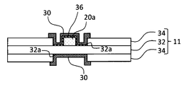
- FIG. 3 is a cross-sectional view taken along line L1-L1 in FIG.
- the insulating member covering a part of the positive electrode lead 20 has an insulating tape 30 and an insulating layer 36 described later.
- the insulating layer 36 is disposed on the outer surface of one end 20 a of the positive electrode lead 20.
- the insulating layer 36 is preferably disposed on the exposed portion 32 a of the positive electrode current collector 32.
- the outer surface of the one end portion 20 a of the positive electrode lead 20 is a surface excluding a portion in contact with the exposed portion 32 a of the positive electrode current collector 32. That is, when the positive electrode lead 20 has a flat plate shape as shown in FIG. 2, the outer surface of the one end portion 20 a faces one main surface opposite to the surface in contact with the exposed portion 32 a of the positive electrode current collector 32. It consists of a pair of side surfaces.
- the shape of the positive electrode lead 20 is not limited to a flat plate, and may be cylindrical or the like.
- the insulating layer 36 is preferably disposed on one main surface and a pair of side surfaces of the one end 20 a of the positive electrode lead 20, but the entire outer surface or one of the one end 20 a of the positive electrode lead 20 is It should be arranged in the department. That is, in the flat positive electrode lead 20, the insulating layer 36 may be disposed on a part or all of one main surface of the one end 20a, or may be disposed on a part or all of a pair of side surfaces Alternatively, they may be disposed on part or all of one main surface and one pair of side surfaces of the one end portion 20a.
- the insulating layer 36 may be formed on the surface of the positive electrode lead 20 in contact with the exposed portion 32 a of the positive electrode current collector 32 at one end 20 a.
- the insulating layer 36 may be formed of the positive electrode lead 20 and the positive electrode current collector 32. Contact resistance may increase and battery performance may decrease. Therefore, the insulating layer 36 is preferably not disposed on the surface of the positive electrode lead 20 in contact with the exposed portion 32 a of the positive electrode current collector 32 at one end 20 a.
- the insulating layer 36 has a higher electrical resistance than the natural oxide film formed naturally on the positive electrode lead 20.
- the insulating layer 36 preferably has an electrical resistance of 1 M ⁇ or more, and more preferably 10 M ⁇ or more.
- the material of the insulating layer 36 is not particularly limited as long as the insulating layer 36 is formed of a material having an insulating property or the like, but preferably contains an inorganic material. Further, in view of mechanical strength, adhesion and the like of the insulating layer 36, it is preferable to contain a binder.
- the inorganic material contained in the insulating layer 36 includes, for example, at least one selected from the group consisting of metal oxides, metal hydroxides, metal nitrides, metal fluorides and metal carbides.
- the binder contained in the insulating layer 36 is preferably a substance which is dissolved in a solvent such as NMP or water, and which is chemically stable in the positive electrode.
- a solvent such as NMP or water
- PTFE polytetrafluoroethylene
- PVdF polyvinylidene fluoride
- polyacrylic acid polyacrylonitrile
- polyisobutylene polyisoprene and the like
- the insulating tape 30 is disposed on both the one principal surface side and the other principal surface side of the positive electrode 11, but one principal surface of the positive electrode 11 on which the positive electrode lead 20 is disposed. It should be placed on the side.
- the insulating tape 30 disposed on the one principal surface side covers the insulating layer 36 disposed on the outer surface of the one end 20 a of the positive electrode lead 20.
- the insulating tape 36 disposed on the one principal surface side covers the insulating layer 36 disposed on the exposed portion 32 a of the positive electrode current collector 32 and the boundary portion between the exposed portion 32 a and the positive electrode active material layer 34. Is preferred.
- the insulating tape 30 disposed on the other main surface side covers the exposed portion 32 a and the boundary between the exposed portion 32 a and the positive electrode active material layer 34.
- the insulating tape 30 includes, for example, a base material layer and an adhesive layer on the base material layer.
- the base material layer is, for example, a layer mainly composed of an organic material, and for example, PPS (polyphenylene sulfide), PEEK (polyether ether ketone), PI (polyimide), PP (polypropylene), PET (polyethylene terephthalate), PBT (Polybutylene terephthalate) and the like.
- the adhesive layer is a layer that adheres to the insulating layer 36, the exposed portion 32a, and the like, and is preferably made of an adhesive such as a rubber-based resin, an acrylic-based resin, or a silicone-based resin.
- FIG. 4 is a view showing an example of a method of arranging the insulating layer and the insulating tape.
- a slurry containing inorganic particles, a binder and the like is applied to the outer surface of the one end 20a of the positive electrode lead 20 and the exposed portion 32a, and the insulating layer 36 is disposed on the outer surface of the one end 20a and the exposed portion 32a.
- the insulating tape 30 having the base layer 30a and the adhesive layer 30b on the base layer 30a is prepared, the adhesive layer 30b of the insulating tape 30 is directed to the insulating layer 36 side, and the insulating tape 30 is on the insulating layer 36. Paste it on (see Figure 4 (B)).
- the insulating layer 36 according to such a procedure is in a state of being adhered to the one end portion 20a and the exposed portion 32a.
- FIG. 5 is a view showing another example of the method of arranging the insulating layer and the insulating tape.
- the insulating layer 36 including inorganic particles, a binder and the like is formed on the adhesive layer 30b of the insulating tape 30 having the adhesive layer 30b on the base layer 30a and the base layer 30a, and the insulating member 39 is manufactured. . (See FIG. 5 (A)).
- the insulating member 39 is pasted so that the insulating layer 36 of the insulating member 39 is disposed on the outer surface of the one end 20a and the exposed portion 32a (see FIG. 5B).
- the insulating layer 36 according to such a procedure is in a non-bonded state with the one end 20a and the exposed portion 32a.
- the insulating layer 36 is disposed on the outer surface of one end 20 a of the positive electrode lead 20 connected to the exposed portion 32 a of the positive electrode current collector 32, and the insulating layer 36 is covered with the insulating tape 30. Even if foreign substances mixed in the metal pierce the insulating tape 30 and the insulating tape 30 is broken, the positive electrode lead 20 on which the insulating layer 36 is disposed is exposed, so internal short circuit between the positive electrode lead 20 and the negative electrode 12 is suppressed. Be Even if foreign matter penetrates the insulating layer 36 and reaches the positive electrode lead 20 and an internal short circuit occurs between the positive electrode lead 20 and the negative electrode 12, the insulating layer 36 existing around the foreign matter serves as a large short circuit resistance. Since it acts, the heat generation of the battery due to the internal short circuit is suppressed, and the rise of the battery temperature is suppressed.
- the insulating layer 36 may be disposed on the outer surface of the one end 20a of the positive electrode lead 20, but as described above, it is preferable to be disposed on a part or all of the exposed portion 32a. As a result, the foreign matter mixed in the battery becomes difficult to contact with the exposed portion 32a, and the occurrence of internal short circuit of the battery is further suppressed.
- the thickness of the insulating layer 36 is preferably, for example, in the range of 2 to 30 ⁇ m. By setting the thickness of the insulating layer 36 to 2 ⁇ m or more, generation of an internal short circuit or a rise in battery temperature when the insulating tape 30 is broken due to foreign matter is suppressed as compared to the case of less than 2 ⁇ m.
- the insulating layer 36 having a thickness of more than 30 ⁇ m may need to reduce the volume of other components in order to accommodate the electrode assembly 14 in the case body 16 having a predetermined size.
- the inorganic material in the insulating layer 36 is, for example, a metal oxide such as aluminum oxide, titanium oxide, zirconium oxide, silicon oxide, manganese oxide, magnesium oxide, nickel oxide or the like, a metal hydroxide such as aluminum hydroxide or magnesium hydroxide And metal nitrides such as titanium nitride, boron nitride, aluminum nitride, magnesium nitride and silicon nitride, metal fluorides such as aluminum fluoride, lithium fluoride, sodium fluoride, magnesium fluoride, calcium fluoride and barium fluoride, Examples thereof include metal carbides such as silicon carbide, boron carbide, titanium carbide and tungsten carbide.
- the inorganic material preferably contains at least one of aluminum oxide, aluminum hydroxide, titanium oxide, magnesium oxide and magnesium hydroxide in terms of chemical stability to the electrolyte and the like.
- the coated amount of the inorganic material in the insulating layer 36 is preferably 0.5 to 10 mg / cm 2 .
- the basis weight of the inorganic material is 0.5 mg / cm 2 or more, the increase in battery temperature due to internal short circuit is suppressed as compared with the case of less than 0.5 mg / cm 2 .
- An insulating layer 36 with a coating weight of inorganic material exceeding 10 mg / cm 2 is not desirable because it may increase costs.
- the average particle diameter of the inorganic material is preferably in the range of 0.05 to 2.0 ⁇ m in that the increase in battery temperature due to internal short circuit can be further suppressed.
- the average particle diameter is a volume average particle diameter measured by a laser diffraction method, and means a median diameter at which a volume integrated value becomes 50% in a particle diameter distribution.
- the average particle size can be measured, for example, using a laser diffraction scattering type particle size distribution measuring apparatus (manufactured by Horiba, Ltd.).
- the insulating tape 30 may cover the insulating layer 36 disposed on the one end 20 a of the positive electrode lead 20, and preferably further covers the insulating layer 36 disposed on the exposed portion 32 a More preferably, part or all of the boundary between the exposed portion 32a and the positive electrode active material layer 34 is covered. This makes it difficult for foreign matter mixed in the battery to come into contact with the exposed portion 32a or the boundary portion, and the occurrence of internal short circuiting of the battery is further suppressed. Furthermore, the insulating tape 30 may cover a part or the whole of the extension 20 b of the positive electrode lead 20. Thereby, the fall of battery performance is suppressed by the contact with the positive electrode lead 20 and another member.
- the thickness of the insulating tape 30 is not particularly limited, but is preferably in the range of 10 to 40 ⁇ m, for example. If the thickness of the insulating tape 30 is less than 10 ⁇ m, the insulating tape 30 is easily broken by foreign matter mixed in the battery. If the thickness of the insulating tape 30 is more than 40 ⁇ m, it may be necessary to reduce the volume of other constituent members in order to fit the electrode assembly 14 in the case main body 16 having a predetermined size.
- Example A1 100 parts by weight of lithium nickel cobalt aluminum complex oxide represented by LiNi 0.88 Co 0.09 Al 0.03 O 2 as a positive electrode active material, 1 part by weight of acetylene black (AB), polyvinylidene fluoride (Then, 1 part by weight of PVDF) was mixed, and an appropriate amount of N-methyl-2-pyrrolidone (NMP) was further added to prepare a positive electrode mixture slurry. Next, the positive electrode mixture slurry was applied to both sides of a positive electrode current collector made of aluminum foil and dried. The resultant was cut into a predetermined electrode size, and rolled using a roller to produce a positive electrode in which a positive electrode active material layer was formed on both sides of a positive electrode current collector.
- AB acetylene black
- PVDF polyvinylidene fluoride
- NMP N-methyl-2-pyrrolidone
- the positive electrode active material layer was not formed in the approximate center of the longitudinal direction of the positive electrode, and an exposed portion (width 6 mm) in which the positive electrode current collector was exposed was formed.
- the coated amount of aluminum oxide of the formed insulating layer was 0.5 mg / cm 2 .
- An insulating tape was prepared in which a pressure-sensitive adhesive layer (thickness 7 ⁇ m) comprising an acrylic pressure-sensitive adhesive was formed on a base material layer comprising a polyimide film having a width of 11 mm and a thickness of 25 ⁇ m. After sticking the insulating layer formed on the PET film to the adhesive layer of the insulating tape, the PET film was peeled off, and the insulating layer (width 7 mm) was transferred to the adhesive layer to produce an insulating member.
- a pressure-sensitive adhesive layer thickness 7 ⁇ m
- a base material layer comprising a polyimide film having a width of 11 mm and a thickness of 25 ⁇ m.
- An insulating member was pasted on the outer surface of one end of the positive electrode lead and the exposed portion so that the insulating layer of the insulating member was disposed. That is, the outer surface of one end of the positive electrode lead and the insulating layer disposed on the exposed portion are covered with the insulating tape.
- the negative electrode current collector is a thin copper foil, and the graphite end, carboxymethyl cellulose (CMC) as a thickener, and styrene-butadiene rubber (SBR) as a binder are used at respective mass ratios.
- CMC carboxymethyl cellulose
- SBR styrene-butadiene rubber
- the slurry was dispersed in water at a ratio of 98: 1: 1 to prepare a negative electrode mixture slurry, which was applied to both sides of the current collector, dried, and compressed by a roll press to a predetermined thickness.
- a negative electrode active material layer was not formed at the end in the longitudinal direction of the negative electrode, and an exposed portion where the negative electrode current collector was exposed was formed, and a nickel negative electrode lead was joined to the exposed portion by ultrasonic welding.
- the insulating tape is obtained by forming a pressure-sensitive adhesive layer made of a rubber-based resin on a base material layer made of a 25 ⁇ m-thick polypropylene film.
- the produced positive electrode and negative electrode were spirally wound via a separator to produce a wound electrode body.
- a separator one having a heat-resistant layer in which fillers of polyamide and alumina were dispersed was used on one side of a microporous polyethylene film.
- the electrode body was housed in a bottomed cylindrical case main body having an outer diameter of 18 mm and a height of 65 mm. At this time, the other end of the positive electrode lead was welded to the sealing body, and the other end of the negative electrode lead was welded to the case main body. Then, 1 mol / L of LiPF 6 is used as a mixed solvent in which ethylene carbonate (EC), ethyl methyl carbonate (EMC) and diethyl carbonate (DEC) are mixed in a volume ratio of 3: 3: 4 in the case main body. After injecting the non-aqueous electrolyte added so as to become, the opening of the case main body was sealed with a gasket and a sealing body to produce a 18650-type cylindrical non-aqueous electrolyte secondary battery.
- EC ethylene carbonate
- EMC ethyl methyl carbonate
- DEC diethyl carbonate
- Example A2 A non-aqueous electrolyte secondary battery was produced in the same manner as in Example A1, except that the coating weight of aluminum oxide in the insulating layer was 2.5 mg / cm 2 .
- Example A3 A non-aqueous electrolyte secondary battery was produced in the same manner as in Example A1, except that the coating amount of aluminum oxide in the insulating layer was 10 mg / cm 2 .
- Example A4 A non-aqueous electrolyte secondary battery was produced in the same manner as in Example A1, except that the average particle diameter of aluminum oxide in the insulating layer was 0.5 ⁇ m.
- Example A5 Similar to Example A1, except that the average particle diameter of aluminum oxide in the insulating layer is 0.5 ⁇ m and the basis weight of aluminum oxide in the insulating layer is 2.5 mg / cm 2 , the non-aqueous electrolyte secondary battery was produced.
- Example A6 A non-aqueous electrolyte secondary battery was produced in the same manner as in Example A1, except that the average particle diameter of aluminum oxide in the insulating layer was 0.5 ⁇ m, and the basis weight of aluminum oxide in the insulating layer was 10 mg / cm 2. did.
- Example A7 A non-aqueous electrolyte secondary battery was produced in the same manner as in Example A1, except that the average particle size of aluminum oxide in the insulating layer was set to 0.05 ⁇ m.
- Example A8 A non-aqueous electrolyte secondary battery as in Example A1, except that the average particle diameter of aluminum oxide in the insulating layer is 0.05 ⁇ m, and the basis weight of aluminum oxide in the insulating layer is 2.5 mg / cm 2. Was produced.
- Example A9 A non-aqueous electrolyte secondary battery was produced in the same manner as in Example A1, except that the average particle diameter of aluminum oxide in the insulating layer was 0.05 ⁇ m, and the basis weight of aluminum oxide in the insulating layer was 10 mg / cm 2. did.
- Example A10 A slurry of 95 parts by weight of aluminum oxide (average particle diameter: 1 ⁇ m) and 5 parts by weight of PVDF dispersed in NMP was applied to the outer surface and exposed part of one end of the positive electrode lead and dried to form an insulating layer. . The coated amount of aluminum oxide of the formed insulating layer was 1 mg / cm 2 . An insulating tape was attached to cover the formed insulating layer. The insulating tape is obtained by forming a pressure-sensitive adhesive layer (thickness 7 ⁇ m) made of an acrylic adhesive on a base material layer made of a polyimide film having a width of 11 mm and a thickness of 25 ⁇ m.
- Comparative Example 1 A non-aqueous electrolyte secondary battery was produced in the same manner as in Example A1, except that the insulating layer was not disposed on the outer surface of one end of the positive electrode lead and the exposed portion.
- the battery temperature at the time of the foreign matter short circuit was measured about the nonaqueous electrolyte secondary battery of each Example and a comparative example.
- the battery temperature at the time of foreign matter short circuit is the maximum reaching when the temperature of the side of the battery when forced short circuit is measured with a thermocouple according to JIS C 8714 by charging foreign matter (nickel pieces) on insulating tape It is a temperature.
- Table 1 shows the results of Examples and Comparative Examples.
- Examples A1 to A2 and Comparative Example 1 internal short circuits occurred due to contamination. However, in Examples A1 to A2 in which the insulating layer is disposed on the outer surface of one end of the positive electrode lead and the insulating layer is covered with the insulating tape, the insulating layer is not disposed on the outer surface of one end of the positive electrode lead.
- the battery temperature at the time of the internal short circuit significantly decreased and the battery temperature increase was suppressed, as compared with the comparative example in which the insulating tape was simply covered.
- Examples A3 to A10 the rise of the battery temperature was suppressed more than Examples A1 and A2, but especially in Examples A6, A8, A9, and A10, the internal short circuit itself did not occur, and the rise of the battery temperature occurred. I could not see it.
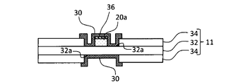
- an insulating layer 46 is formed on the outer surface of the one end 20 a of the positive electrode lead 20.
- the insulating layer 46 is formed on one main surface of the one end 20 a of the positive electrode lead 20, but the invention is not limited thereto.
- the entire or a part of the outer surface of the one end 20 a of the positive electrode lead 20 It should just be formed. That is, in the flat positive electrode lead 20, the insulating layer 46 may be formed on a part or all of one main surface of the one end 20a, or may be formed on a part or all of a pair of side surfaces Alternatively, it may be formed on part or all of one main surface and one pair of side surfaces of the one end portion 20a.
- the insulating layer 46 is different from the natural oxide film formed naturally on the positive electrode lead 20, and has higher electrical resistance than the natural oxide film.
- the insulating layer 46 preferably has an electrical resistance of 1 M ⁇ or more, and more preferably 10 M ⁇ or more.
- the insulating layer 46 may be, for example, an oxide film such as an anodized film, a phosphate film, a chromate film (chromate film), a stannate film, a fluoride film, etc. From the point of view, oxide films such as anodized films and phosphate films are preferable.
- the phosphate film is formed, for example, by immersing the positive electrode lead 20 containing aluminum or an aluminum-based alloy in a phosphate solution for a predetermined time. It is desirable that the positive electrode lead 20 after being immersed in the solution be dried, for example, in the range of 30 ° C. to 50 ° C.
- the phosphate solution is, for example, a solution containing phosphoric acid, chromic anhydride and fluoride, or phosphoric acid, monobasic zinc phosphate and fluorine in that an insulating, highly dense insulating layer 46 is obtained, etc. It is preferable to use a solution containing a halide.
- a phosphoric acid chromate film (specific composition is, for example, Al 2 O 3 , CrPO 4, etc.) is formed. Further, by immersing the positive electrode lead 20 in a solution containing phosphoric acid, primary zinc phosphate and fluoride, a zinc phosphate film (specific composition is, for example, Zn 3 (PO 4 ) 2 , AlPO 4 etc. Is formed.
- the anodized film is formed, for example, by the method defined in JIS H 9500 and JIS H 9501.
- an anodic oxide film (alumite) is formed by immersing the positive electrode lead 20 containing aluminum or an alloy mainly composed of aluminum in a 20% sulfuric acid solution and anodizing it with an applied voltage of 20 V.
- the specific composition of the said anodic oxide film is aluminum oxide etc., for example.
- the solution is not limited to sulfuric acid, and may be, for example, phosphoric acid, oxalic acid and the like.
- oxide films other than anodized films include boehmite films and the like. These oxide films are formed, for example, by hydrothermal treatment. Among the oxide films, an anodized film is preferred in that an oxide film having high insulating properties and high density can be obtained.
- the insulating film 36 may have a single layer structure such as an oxide film such as an anodic oxide film or a phosphate film, or may have a laminated structure in which an oxide film such as an anodic oxide film or a phosphate film is laminated.
- the insulating tape 30 shown in FIGS. 2 and 6 is disposed on both the one principal surface side and the other principal surface side of the positive electrode 11, it is disposed on the one principal surface side of the positive electrode 11 on which the positive electrode lead 20 is disposed. It should be done.
- the insulating tape 30 disposed on the one principal surface side covers the boundary between the insulating layer 46 formed on the one end 20a of the positive electrode lead 20, the exposed portion 32a, and the exposed portion 32a and the positive electrode active material layer 34. ing.
- the insulating tape 30 disposed on the other main surface side covers the exposed portion 32 a and the boundary between the exposed portion 32 a and the positive electrode active material layer 34.
- the insulating tape 30 should just be comprised from the base material layer at least, and the adhesion layer is not an essential component.
- an adhesive may be applied to the affixing site and the insulating tape may be attached thereon.
- the insulating layer 46 is formed on the outer surface of the one end 20 a of the positive electrode lead 20 connected to the exposed portion 32 a of the positive electrode current collector 32, and the insulating layer 46 is covered with the insulating tape 30. Even if foreign materials mixed in the metal pierce the insulating tape 30 and the insulating tape 30 is broken, the positive electrode lead 20 on which the insulating layer 46 is formed is exposed, so internal short circuit between the positive electrode lead 20 and the negative electrode 12 is suppressed. Be Even if foreign matter penetrates the insulating layer 46 and reaches the positive electrode lead 20 and an internal short circuit occurs between the positive electrode lead 20 and the negative electrode 12, the insulating layer 46 present around the foreign matter is a large short circuit resistance. Since it acts, the heat generation of the battery due to the internal short circuit is suppressed, and the rise of the battery temperature is suppressed.
- the insulating layer 46 may be formed on the outer surface of the one end 20 a of the positive electrode lead 20, but is preferably formed on the extended portion 20 b of the positive electrode lead 20. Thereby, the conduction
- the insulating layer 46 may be formed on a part of the extending part 20 b or may be formed on the whole.
- the insulating layer 46 may be formed on the other end 20c (see FIG. 1) of the positive electrode lead 20, it is shown in FIG. 1 when the insulating layer 46 is formed on the other end 20c of the positive electrode lead 20.
- the contact resistance with the sealing body 17 may increase and the battery performance may decrease. Therefore, the insulating layer 466 is preferably not formed on the other end 20 c of the positive electrode lead 20.
- the thickness of the insulating layer 46 is preferably, for example, in the range of 2 to 30 ⁇ m.
- the thickness of the insulating layer 46 is preferably, for example, in the range of 2 to 30 ⁇ m.
- the puncture strength of the insulating layer 46 is preferably higher than the puncture strength of the insulating tape 30. This makes it possible to effectively suppress the occurrence of the internal short circuit of the battery.
- the method of measuring the puncture strength is described in the example section.
- the insulating tape 30 may cover the insulating layer 46 formed on the one end 20 a of the positive electrode lead 20, and further, a part or all of the exposed part 32 a, the exposed part 32 a and the positive electrode active material layer 34 It is desirable to cover a part or all of the boundary of the This makes it difficult for foreign matter mixed in the battery to come into contact with the exposed portion 32a or the boundary portion, and the occurrence of internal short circuiting of the battery is further suppressed. Furthermore, the insulating tape 30 may cover a part or the whole of the extension 20 b of the positive electrode lead 20. Thereby, the internal short circuit by the contact with the positive electrode lead 20 and another member is suppressed.
- Example B1 100 parts by weight of lithium nickel cobalt aluminum complex oxide represented by LiNi 0.88 Co 0.09 Al 0.03 O 2 as a positive electrode active material, 1 part by weight of acetylene black (AB), polyvinylidene fluoride (A positive electrode mixture slurry was prepared by mixing PVdF) with 1 part by weight and further adding an appropriate amount of N-methyl-2-pyrrolidone (NMP). Next, the positive electrode mixture slurry was applied to both sides of a positive electrode current collector made of aluminum foil and dried. The resultant was cut into a predetermined electrode size, and rolled using a roller to produce a positive electrode in which a positive electrode active material layer was formed on both sides of a positive electrode current collector. The positive electrode active material layer was not formed in a substantially central portion in the longitudinal direction of the positive electrode, and an exposed portion in which the positive electrode current collector was exposed was formed.
- AB acetylene black
- NMP N-methyl-2-pyrrolidone
- An aluminum positive electrode lead having a thickness of 150 ⁇ m and a width of 3.5 mm was cut into a predetermined length.
- this positive electrode lead after masking the exposed part of the positive electrode current collector and the part to be welded to the sealing body, it is immersed in a 20% sulfuric acid solution, anodized at an applied voltage of 20 V, and 2 ⁇ m thick on the positive electrode lead An anodic oxide film was formed.
- the puncture strength of the anodized film was 1N.
- the puncture strength of the anodized film was measured as follows. A stainless steel nail (diameter 3 mm, tip angle 35 °) is pressed against the anodized film on the positive electrode lead, and the electrical resistance between the stainless steel nail and the positive electrode lead is measured while increasing the load of the stainless steel nail. Then, a load at which an electrical resistance indicating dielectric breakdown is observed is taken as a breaking strength.
- the positive electrode lead In the positive electrode lead, a portion where the anodized film was not formed was brought into contact with the exposed portion of the positive electrode current collector, and was joined by ultrasonic welding. That is, the positive electrode lead has one end connected to the exposed portion, an extension extending outside the peripheral edge of the positive electrode current collector, and the other end connected to the sealing member at the tip end side from the extension It becomes the positive electrode lead which has an anodic oxide film in the outer surface and extension part of one end.
- the negative electrode current collector is a thin copper foil, and the graphite end, carboxymethyl cellulose (CMC) as a thickener, and styrene-butadiene rubber (SBR) as a binder are used at respective mass ratios.
- CMC carboxymethyl cellulose
- SBR styrene-butadiene rubber
- the slurry was dispersed in water at a ratio of 98: 1: 1 to prepare a negative electrode mixture slurry, which was applied to both sides of the current collector, dried, and compressed by a roll press to a predetermined thickness.
- a negative electrode active material layer was not formed at the end in the longitudinal direction of the negative electrode, and an exposed portion where the negative electrode current collector was exposed was formed, and a nickel negative electrode lead was joined to the exposed portion by ultrasonic welding.
- the anodized film formed on the outer surface of one end of the positive electrode lead and the exposed portion were covered with an insulating tape. Also on the negative electrode side, the negative electrode lead on the exposed portion and the exposed portion were covered with an insulating tape.
- the insulating tape one composed of a base material layer made of a 25 ⁇ m thick polyimide film and an adhesive layer made of a rubber-based resin was used.
- the puncture strength of the insulating tape was 2N.
- the puncture breaking strength of the insulating tape was measured as follows. Press the stainless steel nail (diameter 3 mm, tip angle 35 °) against the insulating tape attached to the 150 ⁇ m thick aluminum plate and measure the electrical resistance of the stainless steel nail and aluminum plate while increasing the load of the stainless steel nail Do. Then, a load at which an electrical resistance indicating dielectric breakdown is observed is taken as a breaking strength.
- the produced positive electrode and negative electrode were spirally wound via a separator to produce a wound electrode body.
- a separator one having a heat-resistant layer in which fillers of polyamide and alumina were dispersed was used on one side of a microporous polyethylene film.
- the electrode body was housed in a bottomed cylindrical case main body having an outer diameter of 18 mm and a height of 65 mm. At this time, the other end of the positive electrode lead was welded to the sealing body, and the other end of the negative electrode lead was welded to the case main body. Then, 1 mol / L of LiPF 6 is used as a mixed solvent in which ethylene carbonate (EC), ethyl methyl carbonate (EMC) and diethyl carbonate (DEC) are mixed in a volume ratio of 3: 3: 4 in the case main body. After injecting the non-aqueous electrolyte added so as to become, the opening of the case main body was sealed with a gasket and a sealing body to produce a 18650-type cylindrical non-aqueous electrolyte secondary battery.
- EC ethylene carbonate
- EMC ethyl methyl carbonate
- DEC diethyl carbonate
- Example B2 A nonaqueous electrolyte secondary battery was produced in the same manner as in Example B1, except that the amount of electricity of the anodizing treatment was adjusted to form an anodized film with a thickness of 10 ⁇ m on the positive electrode lead.
- the puncture strength of the anodized film was 2N.
- Example B3 A nonaqueous electrolyte secondary battery was produced in the same manner as in Example B1, except that the amount of electricity of the anodizing treatment was adjusted to form an anodized film with a thickness of 15 ⁇ m on the positive electrode lead.
- the puncture strength of the anodized film was 2.7 N.
- Example B4 A non-aqueous electrolyte secondary battery was produced in the same manner as in Example B1, except that the amount of electricity of the anodizing treatment was adjusted to form an anodized film with a thickness of 20 ⁇ m on the positive electrode lead.
- the puncture strength of the anodized film was 3.1 N.
- Example B5 A nonaqueous electrolyte secondary battery was produced in the same manner as in Example B1, except that the amount of electricity of the anodizing treatment was adjusted to form an anodized film with a thickness of 25 ⁇ m on the positive electrode lead.
- the puncture strength of the anodized film was 3.5N.
- Example B6 A non-aqueous electrolyte secondary battery was produced in the same manner as Example B1, except that the amount of electricity of the anodizing treatment was adjusted to form an anodized film with a thickness of 30 ⁇ m on the positive electrode lead. The puncture strength of the anodized film was 3.7 N.
- Comparative Example 2 A non-aqueous electrolyte secondary battery was produced in the same manner as in Example B1, except that no anodized film was formed on the positive electrode lead.
- the battery temperature at the time of the foreign matter short circuit was measured about the nonaqueous electrolyte secondary battery of each Example and a comparative example.
- the battery temperature at the time of foreign matter short circuit is the maximum reaching when the temperature of the side of the battery when forced short circuit is measured with a thermocouple according to JIS C 8714 by charging foreign matter (nickel pieces) on insulating tape It is a temperature.
- Table 2 shows the results of Examples and Comparative Examples.
- Examples B1 to B2 and Comparative Example 2 internal short circuits occurred due to contamination.
- the insulating film is formed on the outer surface of one end of the positive electrode lead and the insulating film is covered with the insulating tape
- the insulating film is not formed on the outer surface of one end of the positive electrode lead.
- Comparative Example 2 in which the insulating tape was simply covered, the battery temperature at the time of the internal short circuit dropped remarkably, and the rise of the battery temperature was suppressed.
Landscapes
- Chemical & Material Sciences (AREA)
- Chemical Kinetics & Catalysis (AREA)
- Electrochemistry (AREA)
- General Chemical & Material Sciences (AREA)
- Engineering & Computer Science (AREA)
- Manufacturing & Machinery (AREA)
- Crystallography & Structural Chemistry (AREA)
- Inorganic Chemistry (AREA)
- Connection Of Batteries Or Terminals (AREA)
- Secondary Cells (AREA)
- Battery Electrode And Active Subsutance (AREA)
Abstract
Une batterie secondaire selon un mode de réalisation de la présente invention comprend une électrode positive, une électrode négative, un fil d'électrode positive qui est électroconnecté à l'électrode positive, et une bande isolante qui recouvre une partie du fil d'électrode positive. Le fil d'électrode positive a : une partie d'extrémité qui est connectée à une partie exposée d'un collecteur d'électrode positive qui constitue l'électrode positive ; et une partie d'extension qui s'étend vers l'extérieur à partir de la partie d'extrémité au-delà de la périphérie du collecteur d'électrode positive. Une couche isolante est disposée sur la surface extérieure de la partie d'extrémité du fil d'électrode positive ; et la couche isolante est recouverte par la bande isolante.
Priority Applications (4)
| Application Number | Priority Date | Filing Date | Title |
|---|---|---|---|
| EP18886503.4A EP3723163A4 (fr) | 2017-12-05 | 2018-10-31 | Batterie secondaire, élément isolant et fil d'électrode positive |
| JP2019558074A JP7213455B2 (ja) | 2017-12-05 | 2018-10-31 | 二次電池、絶縁部材及び正極リード |
| CN201880078780.8A CN111448687B (zh) | 2017-12-05 | 2018-10-31 | 二次电池 |
| US16/878,906 US11437619B2 (en) | 2017-12-05 | 2020-05-20 | Secondary battery, insulating member and positive electrode lead |
Applications Claiming Priority (4)
| Application Number | Priority Date | Filing Date | Title |
|---|---|---|---|
| JP2017233737 | 2017-12-05 | ||
| JP2017-233737 | 2017-12-05 | ||
| JP2017234057 | 2017-12-06 | ||
| JP2017-234057 | 2017-12-06 |
Related Child Applications (1)
| Application Number | Title | Priority Date | Filing Date |
|---|---|---|---|
| US16/878,906 Continuation US11437619B2 (en) | 2017-12-05 | 2020-05-20 | Secondary battery, insulating member and positive electrode lead |
Publications (1)
| Publication Number | Publication Date |
|---|---|
| WO2019111597A1 true WO2019111597A1 (fr) | 2019-06-13 |
Family
ID=66749927
Family Applications (1)
| Application Number | Title | Priority Date | Filing Date |
|---|---|---|---|
| PCT/JP2018/040428 WO2019111597A1 (fr) | 2017-12-05 | 2018-10-31 | Batterie secondaire, élément isolant et fil d'électrode positive |
Country Status (5)
| Country | Link |
|---|---|
| US (1) | US11437619B2 (fr) |
| EP (1) | EP3723163A4 (fr) |
| JP (1) | JP7213455B2 (fr) |
| CN (1) | CN111448687B (fr) |
| WO (1) | WO2019111597A1 (fr) |
Cited By (4)
| Publication number | Priority date | Publication date | Assignee | Title |
|---|---|---|---|---|
| WO2021049376A1 (fr) * | 2019-09-13 | 2021-03-18 | 株式会社村田製作所 | Batterie, dispositif électronique et outil électrique |
| JPWO2019194181A1 (ja) * | 2018-04-06 | 2021-04-08 | 三洋電機株式会社 | 非水電解質二次電池 |
| CN114843442A (zh) * | 2022-07-04 | 2022-08-02 | 宁德新能源科技有限公司 | 电化学装置及电子设备 |
| WO2023145679A1 (fr) * | 2022-01-28 | 2023-08-03 | パナソニックエナジー株式会社 | Batterie rechargeable à électrolyte non aqueux |
Families Citing this family (3)
| Publication number | Priority date | Publication date | Assignee | Title |
|---|---|---|---|---|
| KR20190098560A (ko) * | 2018-02-14 | 2019-08-22 | 삼성에스디아이 주식회사 | 전극 조립체 및 이를 포함하는 이차전지 |
| KR20210077512A (ko) * | 2019-12-17 | 2021-06-25 | 주식회사 엘지에너지솔루션 | 내부 단락 평가용 전지 셀 및 이를 이용한 전지 셀의 내부 단락 평가 방법 |
| US11462723B2 (en) * | 2020-10-28 | 2022-10-04 | GM Global Technology Operations LLC | Electrochemical cells with copper-free electrodes and methods for manufacturing the same |
Citations (6)
| Publication number | Priority date | Publication date | Assignee | Title |
|---|---|---|---|---|
| JPH09134729A (ja) * | 1995-11-09 | 1997-05-20 | Matsushita Electric Ind Co Ltd | 非水電解液電池 |
| JP2004311282A (ja) * | 2003-04-09 | 2004-11-04 | Matsushita Electric Ind Co Ltd | 非水電解液二次電池の製造方法 |
| JP2007095423A (ja) * | 2005-09-28 | 2007-04-12 | Dainippon Printing Co Ltd | リチウムイオン電池タブ及びその製造方法並びにそれを用いたリチウムイオン電池 |
| JP2012164470A (ja) * | 2011-02-04 | 2012-08-30 | Sanyo Electric Co Ltd | 積層式電池およびその製造方法 |
| JP2014089856A (ja) | 2012-10-30 | 2014-05-15 | Sony Corp | 電池、電極、電池パック、電子機器、電動車両、蓄電装置および電力システム |
| JP2014135169A (ja) * | 2013-01-09 | 2014-07-24 | Sumitomo Electric Ind Ltd | 非水電解質蓄電デバイス用のリード部材およびその製造方法 |
Family Cites Families (15)
| Publication number | Priority date | Publication date | Assignee | Title |
|---|---|---|---|---|
| CH658342A5 (de) * | 1983-01-07 | 1986-10-31 | Sonval S A | Gasdichte primaerbatterie. |
| JP4188613B2 (ja) * | 2002-03-13 | 2008-11-26 | 松下電器産業株式会社 | 非水電解液電池およびその製造方法 |
| KR101005448B1 (ko) * | 2006-03-13 | 2011-01-05 | 닛본 덴끼 가부시끼가이샤 | 필름 외장 전기 디바이스 |
| JP2009163942A (ja) * | 2007-12-28 | 2009-07-23 | Panasonic Corp | 非水系二次電池およびその製造方法 |
| JP5389368B2 (ja) * | 2008-03-28 | 2014-01-15 | 三洋電機株式会社 | 密閉型電池 |
| JP2010055906A (ja) * | 2008-08-28 | 2010-03-11 | Sanyo Electric Co Ltd | 非水電解質二次電池 |
| JP5701688B2 (ja) * | 2011-01-31 | 2015-04-15 | 三洋電機株式会社 | 積層式電池およびその製造方法 |
| JP6044083B2 (ja) * | 2011-06-21 | 2016-12-14 | 日産自動車株式会社 | 積層型電池およびその製造方法 |
| KR20140011962A (ko) * | 2012-07-20 | 2014-01-29 | 스미토모 덴키 고교 가부시키가이샤 | 탭 리드 및 전지 |
| CN105359303B (zh) * | 2013-07-01 | 2019-07-26 | 远景Aesc能源元器件有限公司 | 非水电解质二次电池用的电极、制造该电极的方法、以及非水电解质二次电池 |
| JP6277034B2 (ja) * | 2014-03-26 | 2018-02-07 | 株式会社日本マイクロニクス | 積層型二次電池 |
| JPWO2016067706A1 (ja) | 2014-10-27 | 2017-08-31 | Necエナジーデバイス株式会社 | 二次電池用電極の製造方法、二次電池用電極、および二次電池 |
| WO2017149961A1 (fr) | 2016-02-29 | 2017-09-08 | パナソニックIpマネジメント株式会社 | Batterie rechargeable à électrolyte non aqueux |
| US20190097228A1 (en) | 2016-03-24 | 2019-03-28 | Sanyo Electric Co., Ltd. | Nonaqueous electrolyte secondary battery |
| KR102469471B1 (ko) * | 2017-12-14 | 2022-11-21 | 주식회사 엘지에너지솔루션 | 리튬 이차 전지용 양극 및 이를 포함하는 이차 전지 |
-
2018
- 2018-10-31 CN CN201880078780.8A patent/CN111448687B/zh active Active
- 2018-10-31 JP JP2019558074A patent/JP7213455B2/ja active Active
- 2018-10-31 WO PCT/JP2018/040428 patent/WO2019111597A1/fr unknown
- 2018-10-31 EP EP18886503.4A patent/EP3723163A4/fr active Pending
-
2020
- 2020-05-20 US US16/878,906 patent/US11437619B2/en active Active
Patent Citations (6)
| Publication number | Priority date | Publication date | Assignee | Title |
|---|---|---|---|---|
| JPH09134729A (ja) * | 1995-11-09 | 1997-05-20 | Matsushita Electric Ind Co Ltd | 非水電解液電池 |
| JP2004311282A (ja) * | 2003-04-09 | 2004-11-04 | Matsushita Electric Ind Co Ltd | 非水電解液二次電池の製造方法 |
| JP2007095423A (ja) * | 2005-09-28 | 2007-04-12 | Dainippon Printing Co Ltd | リチウムイオン電池タブ及びその製造方法並びにそれを用いたリチウムイオン電池 |
| JP2012164470A (ja) * | 2011-02-04 | 2012-08-30 | Sanyo Electric Co Ltd | 積層式電池およびその製造方法 |
| JP2014089856A (ja) | 2012-10-30 | 2014-05-15 | Sony Corp | 電池、電極、電池パック、電子機器、電動車両、蓄電装置および電力システム |
| JP2014135169A (ja) * | 2013-01-09 | 2014-07-24 | Sumitomo Electric Ind Ltd | 非水電解質蓄電デバイス用のリード部材およびその製造方法 |
Non-Patent Citations (1)
| Title |
|---|
| See also references of EP3723163A4 |
Cited By (6)
| Publication number | Priority date | Publication date | Assignee | Title |
|---|---|---|---|---|
| JPWO2019194181A1 (ja) * | 2018-04-06 | 2021-04-08 | 三洋電機株式会社 | 非水電解質二次電池 |
| JP7343482B2 (ja) | 2018-04-06 | 2023-09-12 | パナソニックエナジー株式会社 | 非水電解質二次電池 |
| WO2021049376A1 (fr) * | 2019-09-13 | 2021-03-18 | 株式会社村田製作所 | Batterie, dispositif électronique et outil électrique |
| WO2023145679A1 (fr) * | 2022-01-28 | 2023-08-03 | パナソニックエナジー株式会社 | Batterie rechargeable à électrolyte non aqueux |
| CN114843442A (zh) * | 2022-07-04 | 2022-08-02 | 宁德新能源科技有限公司 | 电化学装置及电子设备 |
| CN114843442B (zh) * | 2022-07-04 | 2022-09-09 | 宁德新能源科技有限公司 | 电化学装置及电子设备 |
Also Published As
| Publication number | Publication date |
|---|---|
| US11437619B2 (en) | 2022-09-06 |
| CN111448687B (zh) | 2023-05-30 |
| JPWO2019111597A1 (ja) | 2020-11-26 |
| EP3723163A4 (fr) | 2021-01-20 |
| JP7213455B2 (ja) | 2023-01-27 |
| EP3723163A1 (fr) | 2020-10-14 |
| CN111448687A (zh) | 2020-07-24 |
| US20200280071A1 (en) | 2020-09-03 |
Similar Documents
| Publication | Publication Date | Title |
|---|---|---|
| WO2019111597A1 (fr) | Batterie secondaire, élément isolant et fil d'électrode positive | |
| JP6911008B2 (ja) | 非水電解質二次電池 | |
| US9048502B2 (en) | Lithium secondary battery and method for producing the same | |
| WO2017163933A1 (fr) | Batterie rechargeable à électrolyte non aqueux | |
| JP5590381B2 (ja) | リチウムイオン二次電池 | |
| US20220140415A1 (en) | Secondary battery | |
| JP7321158B2 (ja) | 非水電解質二次電池 | |
| JP7246196B2 (ja) | 全固体リチウム二次電池 | |
| JP7458008B2 (ja) | 二次電池及び絶縁部材 | |
| WO2018020896A1 (fr) | Batterie secondaire à électrolyte non aqueux | |
| JP6887103B2 (ja) | 非水電解質二次電池 | |
| US20240145681A1 (en) | Negative electrode for nonaqueous electrolyte secondary batteries, and nonaqueous electrolyte secondary battery | |
| WO2022202395A1 (fr) | Batterie cylindrique | |
| JP4830295B2 (ja) | 非水電解液二次電池 | |
| JPWO2019244817A1 (ja) | 非水電解質二次電池 | |
| WO2019049886A1 (fr) | Électrode et batterie secondaire au lithium-ion | |
| WO2023182087A1 (fr) | Batterie secondaire à électrolyte non aqueux | |
| US20220302508A1 (en) | Non-aqueous electrolyte secondary battery and method for producing non-aqueous electrolyte secondary battery | |
| WO2022080175A1 (fr) | Accumulateur à électrolyte non aqueux cylindrique | |
| EP4099429A1 (fr) | Batterie secondaire à électrolyte non aqueux | |
| WO2021049471A1 (fr) | Batterie secondaire à électrolyte non aqueux | |
| EP3958351A1 (fr) | Batterie secondaire à électrolyte non aqueux | |
| TW201941483A (zh) | 非水電解質二次電池及非水電解質二次電池之製造方法 |
Legal Events
| Date | Code | Title | Description |
|---|---|---|---|
| 121 | Ep: the epo has been informed by wipo that ep was designated in this application |
Ref document number: 18886503 Country of ref document: EP Kind code of ref document: A1 |
|
| ENP | Entry into the national phase |
Ref document number: 2019558074 Country of ref document: JP Kind code of ref document: A |
|
| NENP | Non-entry into the national phase |
Ref country code: DE |
|
| ENP | Entry into the national phase |
Ref document number: 2018886503 Country of ref document: EP Effective date: 20200706 |