WO2019111407A1 - Dispositif et procédé d'enregistrement d'étage de destination d'ascenseur - Google Patents
Dispositif et procédé d'enregistrement d'étage de destination d'ascenseur Download PDFInfo
- Publication number
- WO2019111407A1 WO2019111407A1 PCT/JP2017/044204 JP2017044204W WO2019111407A1 WO 2019111407 A1 WO2019111407 A1 WO 2019111407A1 JP 2017044204 W JP2017044204 W JP 2017044204W WO 2019111407 A1 WO2019111407 A1 WO 2019111407A1
- Authority
- WO
- WIPO (PCT)
- Prior art keywords
- destination floor
- coordinate
- touch
- elevator
- user
- Prior art date
Links
Images

Classifications
-
- B—PERFORMING OPERATIONS; TRANSPORTING
- B66—HOISTING; LIFTING; HAULING
- B66B—ELEVATORS; ESCALATORS OR MOVING WALKWAYS
- B66B1/00—Control systems of elevators in general
- B66B1/02—Control systems without regulation, i.e. without retroactive action
- B66B1/06—Control systems without regulation, i.e. without retroactive action electric
- B66B1/14—Control systems without regulation, i.e. without retroactive action electric with devices, e.g. push-buttons, for indirect control of movements
-
- B—PERFORMING OPERATIONS; TRANSPORTING
- B66—HOISTING; LIFTING; HAULING
- B66B—ELEVATORS; ESCALATORS OR MOVING WALKWAYS
- B66B1/00—Control systems of elevators in general
- B66B1/34—Details, e.g. call counting devices, data transmission from car to control system, devices giving information to the control system
- B66B1/46—Adaptations of switches or switchgear
-
- G—PHYSICS
- G06—COMPUTING; CALCULATING OR COUNTING
- G06F—ELECTRIC DIGITAL DATA PROCESSING
- G06F3/00—Input arrangements for transferring data to be processed into a form capable of being handled by the computer; Output arrangements for transferring data from processing unit to output unit, e.g. interface arrangements
- G06F3/01—Input arrangements or combined input and output arrangements for interaction between user and computer
- G06F3/02—Input arrangements using manually operated switches, e.g. using keyboards or dials
- G06F3/023—Arrangements for converting discrete items of information into a coded form, e.g. arrangements for interpreting keyboard generated codes as alphanumeric codes, operand codes or instruction codes
-
- G—PHYSICS
- G06—COMPUTING; CALCULATING OR COUNTING
- G06F—ELECTRIC DIGITAL DATA PROCESSING
- G06F3/00—Input arrangements for transferring data to be processed into a form capable of being handled by the computer; Output arrangements for transferring data from processing unit to output unit, e.g. interface arrangements
- G06F3/01—Input arrangements or combined input and output arrangements for interaction between user and computer
- G06F3/03—Arrangements for converting the position or the displacement of a member into a coded form
- G06F3/041—Digitisers, e.g. for touch screens or touch pads, characterised by the transducing means
-
- G—PHYSICS
- G06—COMPUTING; CALCULATING OR COUNTING
- G06F—ELECTRIC DIGITAL DATA PROCESSING
- G06F3/00—Input arrangements for transferring data to be processed into a form capable of being handled by the computer; Output arrangements for transferring data from processing unit to output unit, e.g. interface arrangements
- G06F3/01—Input arrangements or combined input and output arrangements for interaction between user and computer
- G06F3/048—Interaction techniques based on graphical user interfaces [GUI]
- G06F3/0487—Interaction techniques based on graphical user interfaces [GUI] using specific features provided by the input device, e.g. functions controlled by the rotation of a mouse with dual sensing arrangements, or of the nature of the input device, e.g. tap gestures based on pressure sensed by a digitiser
- G06F3/0488—Interaction techniques based on graphical user interfaces [GUI] using specific features provided by the input device, e.g. functions controlled by the rotation of a mouse with dual sensing arrangements, or of the nature of the input device, e.g. tap gestures based on pressure sensed by a digitiser using a touch-screen or digitiser, e.g. input of commands through traced gestures
Definitions
- the present invention relates to an elevator destination floor registration device having a function of preventing erroneous registration of a destination floor, and an elevator destination floor registration method.
- the following operation procedure has been proposed as a conventional technique in which a visually impaired person registers a destination floor via a touch panel destination floor registration device.
- the conventional device has a function of making a floor of the floor corresponding to the touch button voice-announced when the user touches the touch button partitioned on the touch panel. Therefore, the visually impaired person can check the position of the desired touch button by referring to the voice announcement while tracing the screen of the touch panel with a finger.
- the visually impaired person can register the destination floor by touching again the desired touch button which has been confirmed (for example, see Patent Document 1).
- the present invention has been made to solve the above problems, and has as its object to obtain an elevator destination floor registration device and an elevator destination floor registration method capable of preventing erroneous registration of a destination floor.
- the present invention relates to an elevator control apparatus according to a touch panel on which a plurality of destination floor buttons for displaying a destination floor operated by a user of the elevator to be displayed and coordinate values of touch input by the user from the touch panel.
- the destination floor registration unit for registering the destination floor in the destination floor registration unit, the destination floor registration unit maintaining the state of the first touch input in which one destination floor button on the touch panel is touched by the user As it is, by performing a second touch input different from the first touch input, it is determined that the destination floor corresponding to the one destination floor button specified by the first touch input is selected by the user, Destination floor
- the elevator destination floor registration device which determines the destination floor to be registered.
- the present invention also provides a touch panel on which a plurality of destination floor buttons are displayed for the user of the elevator to operate and input a destination floor.
- a destination floor registration unit that performs destination floor registration in the elevator control device according to coordinate values of touch input by a user from the touch panel;
- a destination floor registration device of an elevator comprising: a destination floor registration method of an elevator to be executed by the destination floor registration unit;
- a first touch input detection step of sequentially detecting, as a first coordinate, the position of the finger when the user traces the touch panel with the finger and performs touch input;
- a stop determination step of determining that tracing has stopped by continuing a state in which the amount of change of the first coordinate sequentially detected is within a stop determination range set in advance for a set time;
- a destination floor detection step of detecting a destination floor which the user is trying to select from a destination floor button displayed at a position on the touch panel corresponding to the first coordinate; The tracing is stopped and the first coordinate is detected based on the judgment result
- Temporary decision step In the state where the destination floor is tentatively determined, the second coordinate is detected by the second touch input detection step, and the destination floor that has been tentatively decided is decided as the destination floor to be registered with the destination floor.
- Destination floor determination step The method of registering the destination floor of an elevator having the
- the user follows the touch panel with a finger, and stops the finger at the desired destination floor button position, and further touches the touch panel with another finger. It has the structure which can perform destination floor registration by destination floor button. Thereby, destination floor registration can be performed without malfunction.
- FIG. 1 is a block diagram showing a destination floor registration device of an elevator according to Embodiment 1 of the present invention.
- the destination floor registration unit 1 determines a destination floor of an elevator car based on an operation by a user and performs destination floor registration.
- the touch panel 2 displays a row destination floor button on the screen and senses a touch operation when the user registers a destination floor.
- a destination floor button of each floor can be allocated in a form divided into sections, and input buttons corresponding to various functions can be allocated other than the destination floor button as needed. It can also be done.
- the announcement device 3 reports the position of the finger being traced by the user, which is specified based on the detection result by the touch panel 2. In addition, when the destination floor registration unit 1 performs the destination floor registration based on the user's operation, the announcement device 3 notifies the registered destination floor.
- the elevator control device 4 performs operation control of the elevator according to the destination floor registration by the destination floor registration unit 1.
- the destination floor registration apparatus of the elevator in this invention is applicable also to a hall or in a car.
- the first touch coordinate detection unit 1 a detects, as a first coordinate, the position of the finger on which the user is tracing the touch panel 2 based on the detection result of the touch panel 2. Furthermore, the first touch coordinate detection unit 1a detects that the user's touch on the touch panel 2 has stopped. For example, the first touch coordinate detection unit 1a can determine that tracing has stopped by continuing the state in which the amount of change in the detected first coordinate falls within the stop determination range set in advance for a set time. .
- the second touch coordinate detection unit 1b is used for the second touch when the user performs a second touch with another finger in a state in which the user stops tracing the touch panel 2 and the finger is touched.
- the position of the finger is detected as a second coordinate.
- the second touch coordinate detection unit 1b can obtain, from the first touch coordinate detection unit 1a, information on the first coordinate in a state where the tracing is stopped. Then, in this state, the second touch coordinate detection unit 1b determines that there is a second touch because the sensing result by the touch panel 2 is obtained for the position different from the first coordinate, and the second coordinate is determined. It can be detected.
- the destination floor detection unit 1c compares the first coordinates obtained from the first touch coordinate detection unit 1a with the positions of the row destination floor buttons arranged on the touch panel 2 so that the user's finger can be used. Determine the selected destination floor.
- the destination floor determination unit 1d acquires, from the first touch coordinate detection unit 1a, the first coordinates in a state in which the user has stopped tracing the touch panel 2. Then, based on the user's operation, the destination floor determination unit 1d compares the first coordinates acquired while the tracing is stopped with the positions of the row destination floor buttons arranged on the touch panel 2. Tentatively determine the designated destination floor.
- the destination floor determination unit 1d determines the tentatively determined destination floor as the destination floor.
- the floor is determined as the destination floor to be registered.
- the input method determination unit 1e determines in advance whether the user inputs using one hand or inputs using both hands.
- the input method determination unit 1e is configured to input the first coordinates detected by the first touch coordinate detection unit 1a and the second coordinates detected by the second touch coordinate detection unit 1b before the input of the destination floor. From this distance, it can be determined whether the user is inputting using one hand or using both hands.
- the first touch coordinate detection unit 1 a and the second touch coordinate detection unit 1 b constitute a touch coordinate detection unit 11.
- the registered floor determination unit 1 f registers the destination floor determined by the destination floor determination unit 1 d in the elevator control device 4.
- the notification control unit 1 g causes the announcement device 3 to announce the destination floor determined by the destination floor detection unit 1 c and the destination floor determined by the destination floor determination unit 1 d.
- the destination floor registration unit 1 having such functions may be configured by software or hardware. If the destination floor registration unit 1 is configured by software, a memory that stores a program that executes each function shown as a functional block in FIG. 1 and various data necessary to execute each function, and a memory And a processor that performs processing in accordance with various programs and various data stored therein.
- the destination floor registration unit 1 is configured by one or more digital circuits that execute various functions when configured by hardware.
- the accompanying various data are incorporated in advance in the digital circuit.
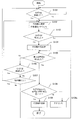
- step S101 the first touch coordinate detection unit 1a determines, based on the result of sensing by the touch panel 2, whether or not the user's finger drag on the touch panel 2 is detected. Then, when the finger drag is detected, the process proceeds to step S102.
- the first touch coordinate detection unit 1a can determine that the state of "sliding" is made by the fact that the coordinates that can be specified from the detection result by the touch panel 2 change with time.
- the first touch coordinate detection unit 1a When the first touch coordinate detection unit 1a detects a trace of a plurality of fingers, it selects one preset point to detect the trace. For example, the first touch coordinate detection unit 1a selects a point having the top coordinates among a plurality of fingers as a touch position. Then, the first touch coordinate detection unit 1a detects the position of the finger with which the user is tracing the touch panel 2 as a first coordinate.
- step S102 the destination floor detection unit 1c determines the destination floor from the first coordinates. Furthermore, the notification control unit 1g causes the announcement device 3 to announce the destination floor determined by the destination floor detection unit 1c by sound, and the process proceeds to step S103. Therefore, the user can easily determine which destination floor button the finger is currently touching by means of a sound announcement while tracing the finger.
- step S103 the first touch coordinate detection unit 1a determines whether the finger dragging has stopped. Then, the first touch coordinate detection unit 1a returns to step S102 when the finger tracing is not stopped, and proceeds to step S104 when the finger tracing is stopped.
- step S104 the destination floor determination unit 1d temporarily determines the destination floor based on the first coordinates detected by the first touch coordinate detection unit 1a in a state in which the finger tracing is stopped, and the process proceeds to step S105. move on.
- step S105 the destination floor determination unit 1d determines whether the second coordinates are detected by the second touch coordinate detection unit 1b. Then, when the second coordinate is detected, the process proceeds to step S108, and when the second coordinate is not detected, the process proceeds to step S106.
- step S106 the first touch coordinate detection unit 1a determines whether a drag has been detected. Then, if the trace is detected, the process returns to step S102, and if the trace is not detected, the process proceeds to step S107.
- step S107 the first touch coordinate detection unit 1a determines whether the finger has left the touch panel 2 or not. If it is determined that the finger has left the touch panel 2, the process returns to step S101, and if it is determined that the finger has not left the touch panel, the process returns to step S105.
- step S108 the time it takes for the second touch coordinate detection unit 1b to detect the second coordinates after the destination floor determination unit 1d determines that the first touch coordinate detection unit 1a stops tracing. It is determined whether or not it is within a preset allowable time range. Then, when the second coordinate is detected within the allowable time range, the destination floor determination unit 1d determines the destination floor corresponding to the first coordinate as the destination floor, and proceeds to S109.
- step S108a the notification control unit 1g causes the user to announce, for example, that the destination floor input operation should be performed again via the announcement device 3.
- the allowable time range is set as a time range for confirming that the second touch is performed with another finger in a state where the user stops tracing and the touch panel 2 is touched by the finger. .
- this allowable time range is set as the first time T1 or more and the second time T2 or less (T1 ⁇ T2).
- the destination floor determination unit 1d can prevent an erroneous detection of a touch due to another unintended factor by determining whether or not the second coordinate is detected in the allowable time range.
- step S109 the registration floor determination unit 1f registers the destination floor determined by the destination floor determination unit 1d in step S108 in the elevator control device 4, and ends the series of processes.
- the destination floor registration device of the elevator performs destination floor registration in a state in which the finger that has been temporarily determined from the screen of touch panel 2 does not separate, so the position of the finger at the time of retouching Misregistration due to misalignment can be prevented.
- another touch input is performed by the user while the state in which the desired destination floor button on the touch panel is touched is maintained, and thus the desired destination is input. It is determined that the destination floor corresponding to the floor button is selected by the user, and the destination floor to be registered in the destination floor can be determined. As a result, it is possible to realize an elevator destination floor registration device and an elevator destination floor registration method capable of preventing erroneous registration of a destination floor.
- the destination floor registration device and the elevator destination floor registration method suitable for the destination floor registration by the visually impaired.
- the first embodiment by monitoring the time difference between two touch inputs, it is possible to add a configuration that can exclude a touch due to an unintended cause. As a result, destination floor registration due to false detection can be prevented.
- the structure in the destination floor registration part 1 shown in FIG. 1 is an example, and it is also possible to put together several components and to comprise.
- Second Embodiment In the first embodiment, the case has been described in which the erroneous detection of the touch due to an unintended cause is prevented by confirming that the second coordinate is detected within the allowable time range.
- the user preselects the input method of one hand or two hands, and the user does not intend based on the distance between the first coordinate and the second coordinate thereafter. A case of preventing erroneous detection of touch due to another factor will be described.
- the input method determination unit 1 e specifies in advance whether the input method for setting the first coordinate and the second coordinate is one hand or both hands based on the selection input by the user. Do. Furthermore, the input method determination unit 1 e calculates the distance between the first coordinate at the time the tracing is stopped and the second coordinate thereafter. Then, if the calculated distance is too long for one-handed input or if it is too near for two-handed input, the destination floor determination unit 1d does not accept the registration operation, but excludes it. Misregistration can be prevented.
- the input method determination unit 1e causes the user to select whether the input method for setting the first coordinate and the second coordinate is one hand or both hands. Specifically, for example, by providing the function button for selecting the input method of one hand or both hands on the touch panel 2, the input method determination unit 1e detects the input method based on the selection operation by the user. Do. Note that the input method determination unit 1e may cause the user to make an announcement prompting the user to select an input method via the notification control unit 1g and the announcement device 3.
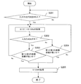
- step S201 After the input method is determined in step S201, the processes of steps S101 to 108a in the first embodiment shown in FIG. 2 are executed, and then the process proceeds to step S202.
- step S202 the destination floor determination unit 1d acquires the selection result of the input method and the calculation result of the distance between the first coordinate and the second coordinate from the input method determination unit 1e. Then, the destination floor determination unit 1d determines whether the input method is one hand based on the selection result, and when the user selects the one hand input method, the process proceeds to step S203, and the input method of both hands is selected. If it is selected, the process proceeds to step S204.
- step S203 based on the calculation result acquired from the input method determination unit 1e, the destination floor determination unit 1d determines whether the distance between the first coordinate and the second coordinate is a short distance range that can be operated with one hand. It is determined whether or not.
- step S205 the process returns to step S101 and subsequent steps.
- step S204 based on the calculation result acquired from the input method determination unit 1e, the destination floor determination unit 1d sets the distance between the first coordinate and the second coordinate within a long distance range that can be operated with both hands. Determine if there is.
- the destination floor determination unit 1d determines that the distance between the first coordinate and the second coordinate is within a long distance range, it determines that the second coordinate is properly read by two-hand operation, The process proceeds to step S205. On the other hand, if it is determined that the distance between the first coordinate and the second coordinate is not within the long distance range, the destination floor determination unit 1d returns to the process after step S101.
- the registered floor determination unit 1f executes the process of step S109 described above, and ends the series of processes as in the first embodiment. In this manner, based on the distance between the first coordinate and the second coordinate, it is possible to prevent an erroneous detection of a touch due to an unintended cause.
- steps S203 and S204 of FIG. 3 if the distance between the first coordinate and the second coordinate is not within the set range, the process returns to the process of steps S101 to 108a in the first embodiment shown in FIG. It is described in. However, the present invention is not limited to such processing.
- step S203 and step S204 in FIG. 3 If it is determined in step S203 and step S204 in FIG. 3 that the distance between the first coordinate and the second coordinate is not within the set range, the user is notified as in the process shown in step S108a in FIG. On the other hand, it is also possible to announce the redo of the destination floor input operation.
- the destination floor registration device of the elevator of the present invention the destination floor registration can be performed without releasing the finger from the touch panel. As a result, it is possible to prevent destination floor registration to an unintended floor due to a user's erroneous operation. Further, since the elevator destination floor registration device of the present invention can be operated with either one hand or both hands, it is possible to provide a convenient destination floor registration system for the user.
- the destination floor registration apparatus of the elevator based on this invention can be added with the function which announces the destination floor button corresponding to the touched position by a sound. Therefore, the touch-panel-type destination floor registration device according to the present invention can be applied even when the visually impaired person registers the destination floor.
- 1 destination floor registration unit 1a first touch coordinate detection unit, 1b second touch coordinate detection unit, 1c destination floor detection unit, 1d destination floor determination unit, 1e input method determination unit, 1f registration floor determination unit, 1g notification Control unit, 2 touch panel, 3 announcement device, 4 elevator control device, touch coordinate detection unit 11.
Landscapes
- Engineering & Computer Science (AREA)
- General Engineering & Computer Science (AREA)
- Theoretical Computer Science (AREA)
- Automation & Control Theory (AREA)
- Human Computer Interaction (AREA)
- Physics & Mathematics (AREA)
- General Physics & Mathematics (AREA)
- Computer Networks & Wireless Communication (AREA)
- Elevator Control (AREA)
Abstract
L'invention concerne un dispositif d'enregistrement d'un étage de destination d'un ascenseur, le dispositif empêchant un enregistrement erroné suite à la sélection et à la détermination d'un étage de destination effectuées sans décoller un doigt d'un écran tactile. Le dispositif d'enregistrement d'un étage de destination d'un ascenseur selon l'invention est disposé au niveau d'un palier ou dans une cabine d'ascenseur, et comporte un écran tactile destiné à être utilisé auxdits endroits, le dispositif étant caractérisé en ce qu'un utilisateur effectue un tracé sur la surface de l'écran tactile ; des premières coordonnées, correspondant à la sélection d'une position au niveau de laquelle le tracé s'est arrêté, sont détectées, et des secondes coordonnées, correspondant à la sélection d'une position au niveau de laquelle la surface de l'écran tactile a été effleurée en dernier, sont détectées ; et les premières coordonnées correspondent à l'étage de destination, et les secondes coordonnées sont considérées comme étant dues à une action visant à déterminer l'étage d'enregistrement. Le dispositif comprend également une unité de notification qui émet une notification concernant l'étage de destination et la détermination de l'étage de destination.
Priority Applications (1)
| Application Number | Priority Date | Filing Date | Title |
|---|---|---|---|
| PCT/JP2017/044204 WO2019111407A1 (fr) | 2017-12-08 | 2017-12-08 | Dispositif et procédé d'enregistrement d'étage de destination d'ascenseur |
Applications Claiming Priority (1)
| Application Number | Priority Date | Filing Date | Title |
|---|---|---|---|
| PCT/JP2017/044204 WO2019111407A1 (fr) | 2017-12-08 | 2017-12-08 | Dispositif et procédé d'enregistrement d'étage de destination d'ascenseur |
Publications (1)
| Publication Number | Publication Date |
|---|---|
| WO2019111407A1 true WO2019111407A1 (fr) | 2019-06-13 |
Family
ID=66750931
Family Applications (1)
| Application Number | Title | Priority Date | Filing Date |
|---|---|---|---|
| PCT/JP2017/044204 WO2019111407A1 (fr) | 2017-12-08 | 2017-12-08 | Dispositif et procédé d'enregistrement d'étage de destination d'ascenseur |
Country Status (1)
| Country | Link |
|---|---|
| WO (1) | WO2019111407A1 (fr) |
Citations (8)
| Publication number | Priority date | Publication date | Assignee | Title |
|---|---|---|---|---|
| JP2003076476A (ja) * | 2001-08-31 | 2003-03-14 | Ricoh Co Ltd | 操作パネルおよび画像形成装置 |
| US20040000453A1 (en) * | 2002-06-27 | 2004-01-01 | Eccleston Jon E. | Method and system to select elevator floors using a single control |
| JP2005149385A (ja) * | 2003-11-19 | 2005-06-09 | Ricoh Co Ltd | 機器操作装置、画像処理装置、プログラム及びコンピュータ読み取り可能な記録媒体 |
| JP2008204275A (ja) * | 2007-02-21 | 2008-09-04 | Konica Minolta Business Technologies Inc | 入力操作装置および入力操作方法 |
| JP2009007074A (ja) * | 2005-10-19 | 2009-01-15 | Mitsubishi Electric Corp | エレベーターの呼び登録装置 |
| JP2014016859A (ja) * | 2012-07-10 | 2014-01-30 | Oki Electric Ind Co Ltd | 入力装置 |
| JP2015138360A (ja) * | 2014-01-22 | 2015-07-30 | コニカミノルタ株式会社 | オブジェクト操作システム及びオブジェクト操作制御プログラム並びにオブジェクト操作制御方法 |
| JP2016115231A (ja) * | 2014-12-17 | 2016-06-23 | コニカミノルタ株式会社 | オブジェクト操作システム及びオブジェクト操作制御プログラム並びにオブジェクト操作制御方法 |
-
2017
- 2017-12-08 WO PCT/JP2017/044204 patent/WO2019111407A1/fr active Application Filing
Patent Citations (8)
| Publication number | Priority date | Publication date | Assignee | Title |
|---|---|---|---|---|
| JP2003076476A (ja) * | 2001-08-31 | 2003-03-14 | Ricoh Co Ltd | 操作パネルおよび画像形成装置 |
| US20040000453A1 (en) * | 2002-06-27 | 2004-01-01 | Eccleston Jon E. | Method and system to select elevator floors using a single control |
| JP2005149385A (ja) * | 2003-11-19 | 2005-06-09 | Ricoh Co Ltd | 機器操作装置、画像処理装置、プログラム及びコンピュータ読み取り可能な記録媒体 |
| JP2009007074A (ja) * | 2005-10-19 | 2009-01-15 | Mitsubishi Electric Corp | エレベーターの呼び登録装置 |
| JP2008204275A (ja) * | 2007-02-21 | 2008-09-04 | Konica Minolta Business Technologies Inc | 入力操作装置および入力操作方法 |
| JP2014016859A (ja) * | 2012-07-10 | 2014-01-30 | Oki Electric Ind Co Ltd | 入力装置 |
| JP2015138360A (ja) * | 2014-01-22 | 2015-07-30 | コニカミノルタ株式会社 | オブジェクト操作システム及びオブジェクト操作制御プログラム並びにオブジェクト操作制御方法 |
| JP2016115231A (ja) * | 2014-12-17 | 2016-06-23 | コニカミノルタ株式会社 | オブジェクト操作システム及びオブジェクト操作制御プログラム並びにオブジェクト操作制御方法 |
Similar Documents
| Publication | Publication Date | Title |
|---|---|---|
| JP6385173B2 (ja) | エレベータのタッチパネル式行き先階登録操作盤およびエレベータのタッチパネル式行き先階登録操作盤における利用者判定方法 | |
| JP2007267388A (ja) | 移動通信端末機及びそのキー入力検出方法 | |
| KR20100005155A (ko) | 엘리베이터의 행선층 등록 장치 | |
| US7404469B2 (en) | Elevator call registration device | |
| EP2617671A1 (fr) | Appareil d'enregistrement d'étage de destination de palier d'ascenseur | |
| JP6436274B1 (ja) | エレベーターの群管理装置 | |
| JP2008065504A (ja) | タッチパネル制御装置およびタッチパネル制御方法 | |
| CN109710083A (zh) | 输入系统 | |
| JP2009289157A (ja) | 表示器、表示器の制御方法、および当該制御方法をコンピュータに実現させるためのプログラム | |
| CN107572325A (zh) | 轿厢操纵箱 | |
| JP2007072536A (ja) | タッチパネル付表示装置およびボタン表示プログラム | |
| WO2019111407A1 (fr) | Dispositif et procédé d'enregistrement d'étage de destination d'ascenseur | |
| US8823681B2 (en) | Method of outputting input position of touch panel | |
| JP6491368B1 (ja) | 操作判定装置、操作判定方法およびプログラム | |
| JP2016055969A (ja) | エレベーターの呼び登録装置 | |
| JP6056646B2 (ja) | エレベーター群管理制御装置 | |
| JP5801728B2 (ja) | タッチパネル装置及びタッチパネル装置の操作処理方法 | |
| JP6567233B2 (ja) | タッチ入力判定装置、タッチパネル入力装置、タッチ入力判定方法、及びタッチ入力判定プログラム | |
| KR101296804B1 (ko) | 엘리베이터 제어 장치 및 방법 | |
| JP2021026422A (ja) | 操作装置とその制御方法 | |
| JP6238271B2 (ja) | エレベータの乗場呼び登録装置およびエレベータの乗場呼び登録方法 | |
| TW201606637A (zh) | 電子裝置及處理多層疊加介面操作之方法 | |
| CN109835784A (zh) | 电梯系统 | |
| TWI475428B (zh) | 指標控制方法與裝置 | |
| JP7167122B2 (ja) | エレベータシステム及び乗場呼び登録切替方法 |
Legal Events
| Date | Code | Title | Description |
|---|---|---|---|
| 121 | Ep: the epo has been informed by wipo that ep was designated in this application |
Ref document number: 17933924 Country of ref document: EP Kind code of ref document: A1 |
|
| NENP | Non-entry into the national phase |
Ref country code: DE |
|
| 122 | Ep: pct application non-entry in european phase |
Ref document number: 17933924 Country of ref document: EP Kind code of ref document: A1 |
|
| NENP | Non-entry into the national phase |
Ref country code: JP |