WO2019102807A1 - 燃料噴射制御装置および燃料噴射制御方法 - Google Patents
燃料噴射制御装置および燃料噴射制御方法 Download PDFInfo
- Publication number
- WO2019102807A1 WO2019102807A1 PCT/JP2018/040454 JP2018040454W WO2019102807A1 WO 2019102807 A1 WO2019102807 A1 WO 2019102807A1 JP 2018040454 W JP2018040454 W JP 2018040454W WO 2019102807 A1 WO2019102807 A1 WO 2019102807A1
- Authority
- WO
- WIPO (PCT)
- Prior art keywords
- current
- fuel injection
- control
- time
- drive current
- Prior art date
- Legal status (The legal status is an assumption and is not a legal conclusion. Google has not performed a legal analysis and makes no representation as to the accuracy of the status listed.)
- Ceased
Links
Images
Classifications
-
- F—MECHANICAL ENGINEERING; LIGHTING; HEATING; WEAPONS; BLASTING
- F02—COMBUSTION ENGINES; HOT-GAS OR COMBUSTION-PRODUCT ENGINE PLANTS
- F02D—CONTROLLING COMBUSTION ENGINES
- F02D41/00—Electrical control of supply of combustible mixture or its constituents
- F02D41/30—Controlling fuel injection
- F02D41/3005—Details not otherwise provided for
-
- F—MECHANICAL ENGINEERING; LIGHTING; HEATING; WEAPONS; BLASTING
- F02—COMBUSTION ENGINES; HOT-GAS OR COMBUSTION-PRODUCT ENGINE PLANTS
- F02D—CONTROLLING COMBUSTION ENGINES
- F02D41/00—Electrical control of supply of combustible mixture or its constituents
- F02D41/02—Circuit arrangements for generating control signals
- F02D41/14—Introducing closed-loop corrections
- F02D41/1401—Introducing closed-loop corrections characterised by the control or regulation method
-
- F—MECHANICAL ENGINEERING; LIGHTING; HEATING; WEAPONS; BLASTING
- F02—COMBUSTION ENGINES; HOT-GAS OR COMBUSTION-PRODUCT ENGINE PLANTS
- F02D—CONTROLLING COMBUSTION ENGINES
- F02D41/00—Electrical control of supply of combustible mixture or its constituents
- F02D41/24—Electrical control of supply of combustible mixture or its constituents characterised by the use of digital means
- F02D41/2406—Electrical control of supply of combustible mixture or its constituents characterised by the use of digital means using essentially read only memories
- F02D41/2409—Addressing techniques specially adapted therefor
- F02D41/2416—Interpolation techniques
-
- F—MECHANICAL ENGINEERING; LIGHTING; HEATING; WEAPONS; BLASTING
- F02—COMBUSTION ENGINES; HOT-GAS OR COMBUSTION-PRODUCT ENGINE PLANTS
- F02D—CONTROLLING COMBUSTION ENGINES
- F02D41/00—Electrical control of supply of combustible mixture or its constituents
- F02D41/30—Controlling fuel injection
- F02D41/32—Controlling fuel injection of the low pressure type
- F02D41/34—Controlling fuel injection of the low pressure type with means for controlling injection timing or duration
- F02D41/345—Controlling injection timing
-
- F—MECHANICAL ENGINEERING; LIGHTING; HEATING; WEAPONS; BLASTING
- F02—COMBUSTION ENGINES; HOT-GAS OR COMBUSTION-PRODUCT ENGINE PLANTS
- F02M—SUPPLYING COMBUSTION ENGINES IN GENERAL WITH COMBUSTIBLE MIXTURES OR CONSTITUENTS THEREOF
- F02M51/00—Fuel-injection apparatus characterised by being operated electrically
- F02M51/06—Injectors peculiar thereto with means directly operating the valve needle
-
- B—PERFORMING OPERATIONS; TRANSPORTING
- B05—SPRAYING OR ATOMISING IN GENERAL; APPLYING FLUENT MATERIALS TO SURFACES, IN GENERAL
- B05B—SPRAYING APPARATUS; ATOMISING APPARATUS; NOZZLES
- B05B12/00—Arrangements for controlling delivery; Arrangements for controlling the spray area
- B05B12/004—Arrangements for controlling delivery; Arrangements for controlling the spray area comprising sensors for monitoring the delivery, e.g. by displaying the sensed value or generating an alarm
-
- F—MECHANICAL ENGINEERING; LIGHTING; HEATING; WEAPONS; BLASTING
- F02—COMBUSTION ENGINES; HOT-GAS OR COMBUSTION-PRODUCT ENGINE PLANTS
- F02D—CONTROLLING COMBUSTION ENGINES
- F02D41/00—Electrical control of supply of combustible mixture or its constituents
- F02D41/02—Circuit arrangements for generating control signals
- F02D41/14—Introducing closed-loop corrections
- F02D41/1401—Introducing closed-loop corrections characterised by the control or regulation method
- F02D2041/1412—Introducing closed-loop corrections characterised by the control or regulation method using a predictive controller
-
- F—MECHANICAL ENGINEERING; LIGHTING; HEATING; WEAPONS; BLASTING
- F02—COMBUSTION ENGINES; HOT-GAS OR COMBUSTION-PRODUCT ENGINE PLANTS
- F02D—CONTROLLING COMBUSTION ENGINES
- F02D41/00—Electrical control of supply of combustible mixture or its constituents
- F02D41/20—Output circuits, e.g. for controlling currents in command coils
- F02D2041/2003—Output circuits, e.g. for controlling currents in command coils using means for creating a boost voltage, i.e. generation or use of a voltage higher than the battery voltage, e.g. to speed up injector opening
-
- F—MECHANICAL ENGINEERING; LIGHTING; HEATING; WEAPONS; BLASTING
- F02—COMBUSTION ENGINES; HOT-GAS OR COMBUSTION-PRODUCT ENGINE PLANTS
- F02D—CONTROLLING COMBUSTION ENGINES
- F02D41/00—Electrical control of supply of combustible mixture or its constituents
- F02D41/20—Output circuits, e.g. for controlling currents in command coils
- F02D2041/202—Output circuits, e.g. for controlling currents in command coils characterised by the control of the circuit
- F02D2041/2058—Output circuits, e.g. for controlling currents in command coils characterised by the control of the circuit using information of the actual current value
-
- F—MECHANICAL ENGINEERING; LIGHTING; HEATING; WEAPONS; BLASTING
- F02—COMBUSTION ENGINES; HOT-GAS OR COMBUSTION-PRODUCT ENGINE PLANTS
- F02D—CONTROLLING COMBUSTION ENGINES
- F02D41/00—Electrical control of supply of combustible mixture or its constituents
- F02D41/20—Output circuits, e.g. for controlling currents in command coils
-
- Y—GENERAL TAGGING OF NEW TECHNOLOGICAL DEVELOPMENTS; GENERAL TAGGING OF CROSS-SECTIONAL TECHNOLOGIES SPANNING OVER SEVERAL SECTIONS OF THE IPC; TECHNICAL SUBJECTS COVERED BY FORMER USPC CROSS-REFERENCE ART COLLECTIONS [XRACs] AND DIGESTS
- Y02—TECHNOLOGIES OR APPLICATIONS FOR MITIGATION OR ADAPTATION AGAINST CLIMATE CHANGE
- Y02T—CLIMATE CHANGE MITIGATION TECHNOLOGIES RELATED TO TRANSPORTATION
- Y02T10/00—Road transport of goods or passengers
- Y02T10/10—Internal combustion engine [ICE] based vehicles
- Y02T10/40—Engine management systems
Definitions
- the present invention relates to a fuel injection control device and a fuel injection control method.
- Patent Document 1 describes a fuel injection pulse width in consideration of the amount of fuel injected from the fuel injection device until the plunger of the fuel injection device actually closes after the fuel injection pulse to the fuel injection device is turned off.
- a fuel injection control device is disclosed that adjusts the amount of fuel injected from the fuel injection device by correcting
- Patent Document 2 measures the current of a coil for driving a plunger of a fuel injection device and calculates the slope of the measured current, and based on the slope of this current, the peak point of the actual current flowing through the coil.
- a fuel injection control device is disclosed that corrects the deviation.
- an object of the present invention is to provide a fuel injection control device capable of controlling the fuel injection amount more accurately.
- a fuel injection control device which controls a fuel injection device, and the control current generation part which generates control current for controlling a fuel injection device, and fuel injection controlled based on control current
- a current acquisition unit that acquires a drive current of the device at predetermined time intervals, a first drive current at a first time acquired by the current acquisition unit, and a second drive current at a second time later than the first time
- a current prediction unit that predicts the third drive current at the third time after the second time
- the control current generation unit is configured to calculate the third drive current at the third time predicted by the current prediction unit.
- the control current is corrected by comparing the predicted power calculated based on the third drive current of the above and the target power calculated based on the predetermined target drive current.
- a control device 1 provided with a fuel injection control device 82 according to an embodiment of the present invention, and an internal combustion engine 100 controlled by the control device 1 will be described.
- the internal combustion engine 100 may have a single cylinder or a plurality of cylinders, the embodiment will be described by exemplifying the case where the fuel injection amount of the fuel injection device 400 of the internal combustion engine 100 having four cylinders is controlled.
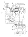
- FIG. 1 is a view for explaining the main configuration of an internal combustion engine 100 and a control device 1.
- the throttle valve 113 is provided with a throttle opening degree sensor 113a for detecting the opening degree of the throttle, and the opening degree information of the throttle valve 113 detected by the throttle opening degree sensor 113a is used as a control device (Electronic Control Unit: ECU 1 is output.
- ECU 1 Electronic Control Unit
- throttle valve 113 an electronic throttle valve driven by an electric motor is used, but any method may be used as long as the flow rate of air can be appropriately adjusted.
- the temperature of the gas flowing into each cylinder 150 is detected by an intake air temperature sensor 115.
- a crank angle sensor 121 is provided radially outside the ring gear 120 attached to the crankshaft 123, and the crank angle sensor 121 detects the rotation angle of the crankshaft 123.
- the crank angle sensor 121 detects the rotation angle of the crankshaft 123 every 10 ° and every combustion cycle.
- a water temperature sensor 122 is provided on a water jacket (not shown) of the cylinder head, and the water temperature sensor 122 detects the temperature of the cooling water of the internal combustion engine 100.
- the vehicle is also provided with an accelerator position sensor (APS) 126 for detecting the displacement amount (depression amount) of the accelerator pedal 125.
- the accelerator position sensor 126 detects the driver's request torque. Do.
- the driver's request torque detected by the accelerator position sensor 126 is output to the control device 1 described later, and the control device 1 controls the throttle valve 113 based on the request torque.
- the fuel stored in the fuel tank 130 is sucked and pressurized by the fuel pump 131, then flows through the fuel pipe 133 provided with the pressure regulator 132, and is guided to the fuel injector (injector) 400.
- the fuel output from the fuel pump 131 is adjusted to a predetermined pressure by the pressure regulator 132, and is injected from the fuel injection device (injector) 400 into each cylinder 150.
- Control of the fuel injection device 400 is performed based on a fuel injection pulse (control signal) of a fuel injection control device 82 of the control device 1 described later.
- the excess fuel after being pressure-regulated by the pressure regulator 132 is returned to the fuel tank 130 via a return pipe (not shown).
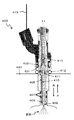
- FIG. 2 is a cross-sectional view for explaining the configuration of the fuel injection device 400. As shown in FIG.
- the fuel injection device 400 is attached to the cylinder head 420 from the nozzle 405 side, and the ring seal 412 and the tip seal 407 seal between the nozzle 405 and the cylinder head 420.
- a plunger 410 is provided slidably along the axial direction of the central axis X.
- a current based on the fuel injection pulse S9 (control signal) transmitted from the fuel injection control unit 82 is supplied to the coil 402 via the power line 419, and a spring is generated by the electromagnetic force generated in the coil 402. It moves in the A direction along the central axis X against the pressing force of 413. At this time, the plunger 410 is guided by the guides 408 and 411.
- a gap is generated between the tip of the plunger 410 and the orifice cup 409 to open the valve.
- the amount of movement of the plunger 410 with respect to the orifice cup 409 is referred to as a lift amount.
- the lift amount of plunger 410 is controlled in accordance with the magnitude of the current based on fuel injection pulse S9.
- the amount of fuel injected is controlled according to the lift amount of the plunger 410.
- the fuel injection device 400 when the fuel injection pulse S9 transmitted from the fuel injection control unit 82 stops, as a result of the current supply to the coil 402 being stopped, the electromagnetic force generated in the coil 402 disappears. Therefore, the plunger 410 is pressed by the spring 413 in the B direction along the central axis X.
- the through hole of the orifice cup 409 is closed at the tip end portion of the plunger 410 and the valve is closed.
- the injection of fuel from the gap between the plunger 410 and the orifice cup 409 is stopped.
- the arrow A direction along the central axis X described above is referred to as the valve opening direction of the fuel injection device 400, and the arrow B direction is referred to as the valve closing direction of the fuel injection device 400.
- the cylinder head (not shown) of the internal combustion engine 100 is provided with a combustion pressure sensor (Cylinder Pressure Sensor: CPS, also called in-cylinder pressure sensor) 140.
- the combustion pressure sensor 140 is provided in each cylinder 150 and detects the pressure (combustion pressure) in the cylinder 150.
- a piezoelectric or gauge pressure sensor is used as the combustion pressure sensor 140 so that the combustion pressure (in-cylinder pressure) in the cylinder 150 can be detected over a wide temperature range.
- Each cylinder 150 is attached with an exhaust manifold 160 for discharging the burned gas (exhaust gas) to the outside of the cylinder 150.
- a three-way catalyst 161 is provided on the exhaust side of the exhaust manifold 160, and the exhaust gas is purified by the three-way catalyst 161 and then discharged to the atmosphere.
- An upstream air-fuel ratio sensor 162 is provided on the upstream side of the three-way catalyst 161, and the upstream air-fuel ratio sensor 162 continuously detects the air-fuel ratio of the exhaust gas discharged from each cylinder 150.
- a downstream air-fuel ratio sensor 163 is provided downstream of the three-way catalyst 161, and the downstream air-fuel ratio sensor 163 outputs a switching detection signal in the vicinity of the stoichiometric air-fuel ratio.
- the downstream air-fuel ratio sensor 163 is an O 2 sensor.
- an ignition plug 200 is provided on the upper portion of each cylinder 150, and sparks are ignited in the mixture of air and fuel in the cylinder 150 by the discharge (ignition) of the ignition plug 200. An explosion occurs and the piston 170 is pushed down. As the piston 170 is depressed, the crankshaft 123 is rotated.
- Output signals from various sensors such as the throttle opening degree sensor 113a, the flow rate sensor 114, the crank angle sensor 121, the accelerator position sensor 126, the water temperature sensor 122, and the combustion pressure sensor 140 are output to the control device 1.
- the control device 1 detects the operating state of the internal combustion engine 100 based on output signals from these various sensors, and detects the amount of air sent into the cylinder 150, the amount of fuel injection from the fuel injection device 400, and the ignition of the spark plug 200. Control timing etc.
- the control device 1 includes an analog input unit 10, a digital input unit 20, an A / D (Analog / Digita) conversion unit 30, a RAM (Random Access Memory) 40, and an MPU (Micro- A processing unit) 50, a read only memory (ROM) 60, an input / output (I / O) port 70, and an output circuit 80.
- an analog input unit 10 a digital input unit 20
- a RAM Random Access Memory
- MPU Micro- A processing unit
- ROM read only memory
- I / O input / output
- the analog input unit 10 includes various sensors such as a throttle opening sensor 113 a, a flow sensor 114, an accelerator position sensor 126, an upstream air-fuel ratio sensor 162, a downstream air-fuel ratio sensor 163, a combustion pressure sensor 140, and a water temperature sensor 122.
- An analog output signal is input.
- An A / D converter 30 is connected to the analog input unit 10.
- the analog output signals from the various sensors input to the analog input unit 10 are subjected to signal processing such as noise removal, and then converted to digital signals by the A / D conversion unit 30 and stored in the RAM 40.
- a digital output signal from the crank angle sensor 121 is input to the digital input unit 20.
- An I / O port 70 is connected to the digital input unit 20, and a digital output signal input to the digital input unit 20 is stored in the RAM 40 via the I / O port 70.
- Each output signal stored in the RAM 40 is arithmetically processed by the MPU 50.
- the MPU 50 executes a control program (not shown) stored in the ROM 60 to calculate the output signal stored in the RAM 40 in accordance with the control program. According to the control program, the MPU 50 calculates a control value defining the operation amount of each actuator (for example, the throttle valve 113, the pressure regulator 132, the spark plug 200, etc.) for driving the internal combustion engine 100 and temporarily stores it in the RAM 40. .
- a control program for example, the throttle valve 113, the pressure regulator 132, the spark plug 200, etc.
- a control value that defines the operation amount of the actuator stored in the RAM 40 is output to the output circuit 80 via the I / O port 70.
- the output circuit 80 includes a fuel injection control unit 82 (see FIG. 3) that controls driving of a plunger 410 (see FIG. 2) of the fuel injection device 400 and an ignition control unit 83 (see FIG. 3) that controls a voltage applied to the spark plug 200. 3) functions are provided.
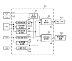
- FIG. 3 is a functional block diagram for explaining the functional configuration of the control device 1.
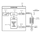
- FIG. 4 is a diagram for explaining the function of the fuel injection control unit 82. As shown in FIG.
- the various functions of the output circuit 80 are realized by the MPU 50 executing the control program stored in the ROM 60, so that the fuel injection control unit 82 of the output circuit 80 controls the fuel injection device 400.
- the discharge control of the spark plug 200 by the ignition control unit 83 is performed.
- the output circuit 80 of the control device 1 includes a general control unit 81, a fuel injection control unit 82, and an ignition control unit 83.
- the overall control unit 81 is connected to the accelerator position sensor 126 and the combustion pressure sensor 140 (CPS), and the required torque (acceleration signal S1) from the accelerator position sensor 126 and the output signal S2 from the combustion pressure sensor 140 Accept
- the overall control unit 81 performs overall control of the fuel injection control unit 82 and the ignition control unit 83 based on the required torque (acceleration signal S1) from the accelerator position sensor 126 and the output signal S2 from the combustion pressure sensor 140. I do.
- the ignition control unit 83 is connected to the cylinder determination unit 84, the angle information generation unit 85, the rotation speed information generation unit 86, the load information generation unit 88, and the water temperature measurement unit 89 in addition to the general control unit 81. Accept each piece of information from them.
- the ignition control unit 83 cuts off the amount of current (energization angle) for energizing the primary coil 310 of the ignition coil 300, the energization start time, and the current for energizing the primary coil 310 based on the received information. Time to fire (ignition time) is calculated.
- the ignition control unit 83 outputs the ignition signal S to the primary coil 310 of the ignition coil 300 based on the calculated amount of energization, the energization start time, and the ignition time, so that discharge control by the ignition plug 200 is performed. Do.
- the fuel injection control unit 82 includes a cylinder discrimination unit 84 that discriminates each cylinder 150 of the internal combustion engine 100, an angle information generation unit 85 that measures the crank angle of the crankshaft 123, and a rotation speed information generation unit that measures the engine rotation speed. 86 are connected to each other, and the cylinder discrimination information S3 from the cylinder discrimination unit 84, the crank angle information S4 from the angle information generation unit 85, and the engine rotation number information S5 from the rotation number information generation unit 86 Accept.
- the fuel injection control unit 82 measures the temperature of the engine coolant water, an intake amount measurement unit 87 that measures the intake amount of air taken into the cylinder 150, a load information generation unit 88 that measures the engine load, and A water temperature measurement unit 89 is connected to the intake amount information S6 from the intake amount measurement unit 87, the engine load information S7 from the load information generation unit 88, and the coolant temperature information S8 from the water temperature measurement unit 89. Accept.
- the fuel injection control unit 82 calculates the injection amount and injection time of the fuel injected from the fuel injection device 400 based on each received information, and generates the fuel generated based on the calculated injection amount of fuel and the injection time.
- the injection pulse S9 is transmitted to the fuel injection device 400.
- the fuel injection control unit 82 includes an arithmetic unit 821, a correction unit 822, a base waveform acquisition unit 823, an A / D converter (Analog to Digital Converter) 824, and D / And an A converter (Digital to Analog Converter) 825.
- the base waveform acquisition unit 823 acquires, from the ROM 60, a base waveform (digital signal) of the fuel injection pulse S9 according to the operating state (target driving force) of the internal combustion engine 100.
- a plurality of base waveforms of the fuel injection pulse S9 are prepared in accordance with the operating state, and are stored in a storage medium such as the ROM 60.
- the base waveform of the fuel injection pulse S9 opens the plunger 410 of the fuel injection device 400 from the closed state, the high current S91 set to a high current value and the opened plunger 410 are held in the open state. Therefore, the holding current S92 is held at a constant current value lower than the high current S91 (see FIG. 5).
- the D / A conversion unit 825 converts the base waveform (digital signal) of the fuel injection pulse S9 acquired by the base waveform acquisition unit 823 into a control current of an analog signal.
- control current is denoted as S9.
- the control current S9 converted into an analog signal by the D / A conversion unit 825 is supplied to the fuel injection device 400 (coil 402).
- the lift amount of the plunger 410 is controlled based on the control current S9.
- An ammeter 430 is provided at one end of the fuel injection device 400 (coil 402), and the ammeter 430 measures the drive current P (analog value) actually flowing through the coil 402.
- the drive current P measured by the ammeter 430 is converted into a digital signal by the A / D conversion unit 824 of the fuel injection control unit 82, and is then transmitted to the calculation unit 821.
- the inflection point Pk of the drive current waveform is determined based on the drive current P of the coil 402 measured at the current measurement timing and the drive current P measured at the previous (preceding) measurement timing. See FIG. 5).
- the waveform of the drive current P flowing through the coil 402 is determined according to the waveform of the control current S9 supplied to the coil 402. Therefore, the calculation unit 821 can detect the inflection point Pk of the waveform of the drive current P (waveform of the control current S9) from the measurement results of the drive current P at at least two different times measured in the past.
- the inflection point Pk means a point at which the slope of the curve on the plane changes, and the waveform after the inflection point Pk can be approximated by a straight line.
- the computation unit 821 computes the predicted value of the drive current P after the inflection point Pk using linear extrapolation.
- straight line extrapolation means finding the predicted value of the subsequent numerical value outside the range of those data based on certain known numerical data.
- Arithmetic unit 821 compares the amount of power calculated based on drive current P after inflection point Pk predicted using linear extrapolation with the amount of power calculated based on control current S9, which is the target value.
- the timing (time) ta at which the drive current P (predicted value) exceeds the control current S9 (target value) is estimated.
- each power amount can be obtained as the area of the drive current P or the control current S9 (for example, refer to the area E shown in FIG. 5).
- the calculation unit 821 When it is determined that the drive current P measured at the predetermined measurement timing already exceeds the control current S9, the calculation unit 821 immediately stops the supply of the fuel injection pulse S9 to the fuel injection device 400.
- the correction unit 822 determines that the drive current P measured at the predetermined measurement timing does not exceed the control current S9, calculates the timing ta where the drive current P exceeds the control current S9, and the timing ta The magnitude or length of the control current S9 (fuel injection pulse S9) is corrected based on
- the acquisition and generation of the control current S9 by the base waveform acquisition unit 823 and the calculation unit 821 described above corresponds to the control current generation unit of the present invention
- the A / D conversion unit 824 acquires the drive current P measured by the ammeter 430.
- the configuration to be performed corresponds to the current acquisition unit of the present invention
- the prediction of the drive current by the arithmetic unit 821 corresponds to the current prediction unit of the present invention.
- the correction of the control current S9 by the arithmetic unit 821 and the correction unit 822 corresponds to the correction of the control current by the control current generation unit of the present invention.
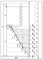
- FIG. 5 is a view for explaining a method of correcting the fuel injection pulse S9 by the fuel injection control unit 82. As shown in FIG. FIG. 5 shows an example of the drive current P and the control current S9, and the predicted value of the drive current P is indicated by a broken line.
- the upper part shows the control current S9 after D / A conversion generated by the fuel injection control unit 82 and the drive current P of the fuel injection device 400 (coil 402) driven based on the control current S9. It shows the relationship.
- the control current S9 generated by the fuel injection device 82 is a high current S91 for opening the plunger 410 of the fuel injection device 400 from the closed state by a predetermined amount, and a holding current S92 for holding the plunger 410 in the open state. It is divided roughly.
- the lower part of FIG. 5 shows measurement timing for measuring the drive current P.
- the drive current P is measured at a predetermined measurement timing based on a predetermined clock frequency. Specifically, the drive current P measures the drive current P at the falling timing of a predetermined clock.
- the falling timing of the predetermined clock is referred to as a measurement timing ADC.
- the fuel injection control unit 82 drives the fuel control device 400 based on the control current S9 obtained by D / A converting the fuel injection pulse S9 acquired from the base waveform acquisition unit 823.
- a magnetic flux is generated in the coil 402 by the control current S9, and the plunger 410 moves in the A direction of the central axis X by this magnetic flux (see FIG. 3). Then, by the movement of the plunger 410, the lift amount of the plunger 410 with respect to the orifice cup 409 is set.
- the fuel injection control unit 82 acquires the drive current P of the fuel injection device 400 (coil 402) from the ammeter 430 at a predetermined measurement timing ADC.
- the drive current acquired at predetermined measurement timings t1 to t6 is denoted by P1 to P6, and the drive current to be acquired at future measurement timing t7 is denoted by P7.
- the computing unit 821 of the fuel injection device 82 measures the drive current P of the coil 402 at predetermined measurement timings t1 to t6, and measures the drive current P measured at each measurement timing t1 to t6. , And sequentially stored in a predetermined storage area of the RAM 40 of the control device 1.
- the drive current P1 at the first measurement timing t1 (first time) and the drive current P2 at the second measurement timing t2 (second time) are read from the RAM 40, and the drive currents P1 and P2 are read.
- the arithmetic unit 821 reads the drive current P2 at the second measurement timing t2 (second time) and the drive current P3 at the third measurement timing t3 (third time) from the RAM 40, and outputs the drive current P2,
- the change rate k2 of P3 is calculated.
- the calculation unit 821 compares the rate of change k1 with the rate of change k2 and determines that the third measurement timing t3 is the inflection point Pk when the respective rates of change match. After this inflection point Pk, the calculation unit 821 predicts future drive currents P4 to P7 by straight line extrapolation (broken line in FIG. 5).
- the calculation unit 821 acquires the drive current P of the coil 402 from the ammeter 430 at measurement timings t4 to t7 based on a predetermined clock frequency also after the third measurement timing t3, and based on the acquired drive current P, The future drive current P is predicted.
- the calculation unit 821 calculates a time ta when the power amount E (predicted value) calculated from the future drive current Pa exceeds the target power amount calculated from the control current S9. In the embodiment, the calculating unit 821 calculates that the predicted power amount E exceeds the target power amount at timing ta.
- the calculation unit 821 determines that the timing ta is less than the next measurement timing t7, the excess power Eo among the power amounts calculated from the drive current P8 predicted at the next measurement timing t7 (FIG.
- the control current S9 at the next measurement timing t7 is corrected to be lower by the amount indicated by dark hatching).
- operation unit 821 performs control to lower predicted drive current P8 so that the amount of power based on predicted drive current P8 at the next measurement timing t7 matches the amount of power based on control current S9. Do.
- the calculation unit 821 corrects the control current S9 so as to reduce the predicted drive current P8 at the next measurement timing t7 to the drive current P7.
- the amount of power based on the corrected drive current P7 can be controlled to match the target drive power, and the lift amount of the plunger 410 can be a target value.
- the calculation unit 821 immediately supplies the control current S9. Stop.
- the fuel injection control unit 82 can minimize the increase in the lift amount due to the predicted power amount E becoming larger than the target power amount.
- the fuel injection controller 82 determines that the predicted electric energy E becomes larger than the target electric energy, the fuel injection controller 82 adjusts the magnitude of the drive current P8 at the next measurement timing t7 or the drive current P8. Instead of adjusting the magnitude, the control current S9 may be adjusted so as to shorten the length of the high current S91 (dotted line in FIG. 5).
- the fuel injection control unit 82 may end the high current S91 at timing te, which is shorter than the time of the next measurement timing t7. Also in this case, the estimated amount of power E can be brought close to the target amount of power, and the lift amount of the plunger 410 can be adjusted with high accuracy.
- the predicted power amount E exceeds the target power amount
- the control current S9 is corrected so as to shorten the length of the holding current S92 following it (in the embodiment, it is shortened by td).
- the fuel injection amount can be controlled more appropriately and accurately by correcting the length of the holding current S91. it can.
- operation unit 821 causes change rates after change rate k2 to be a predetermined change rate.
- the control current S9 may be corrected.
- the power amount prediction method by the calculation unit 821 by linear extrapolation after the inflection point as described above in consideration of the processing load of the CPU or the like.
- spline extrapolation or polynomial approximation extrapolation may be used, or a combination thereof may be used for prediction.
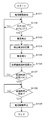
- FIG. 6 is a flowchart of a control method of the fuel control device 400 by the fuel injection control unit 82.
- step S101 the fuel injection control unit 82 supplies a control current S9 (fuel injection pulse S9) according to the operating state of the internal combustion engine 100 to the fuel injection device 400, and the current of the plunger 410 Start driving.
- a control current S9 fuel injection pulse S9
- step S102 the fuel injection control unit 82 determines whether it is the next measurement timing ADC of the drive current P flowing through the coil 402 by the ammeter 430 and determines that it is the next measurement timing (step S102). : YES), proceed to step S103, and if it is determined that it is not the next measurement timing ADC (step S102: NO), the process of step S102 is repeated every predetermined period until the next measurement timing is reached.
- step S103 the fuel injection control unit 82 acquires the drive current P flowing through the coil 402 measured by the ammeter 430 based on the measurement timing ADC of the predetermined sampling clock.
- step S104 the fuel injection control unit 82 stores the drive current P acquired in step S103 in a storage device such as the RAM 40.
- step S105 the fuel injection control unit 82 reads the drive current P measured at the previous measurement timing stored in step S103 and the drive current P measured at the current measurement timing from the RAM 40, and sets these drive currents P as the drive current P. Based on this, it is determined whether the drive current P acquired this time is the inflection point Pk, and if it is determined that it is the inflection point Pk, the drive current P after the inflection point Pk is calculated by linear extrapolation.
- step S106 the fuel injection control unit 82 calculates the amount of electric power based on the predicted value of the drive current P calculated in step S105, and drives only the lift amount necessary for driving the plunger 410 based on the operating state of the internal combustion engine 100. Compare with the target power amount to
- the fuel injection control unit 82 calculates the timing Te at which the predicted power amount exceeds the target power amount, based on the comparison between the predicted value of the power amount and the target power amount.
- step S107 the fuel injection control unit 82 determines whether the excess timing te calculated in step S106 is less than the next measurement timing ADC. If the fuel injection control unit 82 determines that the excess timing te is less than the next measurement timing ADC (step S107: YES), the fuel injection control unit 82 proceeds to step S108 and determines that the excess timing te is greater than or equal to the next measurement timing ADC In the case (step S107: NO), the process returns to step S102, and the drive current P is acquired at the next measurement timing ADC.
- step S108 the fuel injection control unit 82 determines whether the excess timing te calculated in step S106 is equal to or less than the current time. If the combustion injection control unit 82 determines that the excess timing te exceeds the current time (it has already exceeded it) (step S108: YES), the process proceeds to step S109, and the control current S9 to the fuel injection device 400 is obtained. Immediately stop the supply of Accordingly, the fuel injection control unit 82 can minimize the fuel injection excess due to the large control current S9.
- the fuel injection control unit 82 determines that the excess timing te does not exceed the current time (after the current time), it waits until the excess timing te exceeds the current time, and the excess timing te is the current time The supply of the control current S9 to the fuel injection device 400 is stopped at the timing when
- a fuel injection control unit 82 (a fuel injection control device) that controls the fuel injection device 400, and a calculation unit 821 that generates a control current S9 for controlling the fuel injection device 400, and a base waveform acquisition unit 823
- the A / D conversion unit 824 acquires the drive current P of the fuel injection device 400 controlled based on the control current S9 at each measurement timing t1 to t6 (predetermined time) based on the counter cycle, and the base waveform acquisition unit 823
- the driving current P1 (first driving current) at the acquired first measurement timing t1 (first time) and the driving current P2 at the second measurement timing t2 (second time) after the first measurement timing t1.
- the control current S9 is corrected by comparing it with the target power amount calculated based on (target drive current).
- the calculation unit 821 calculates the excess timing te at which the predicted power amount E exceeds the target power amount and determines that the excess timing te is less than the next measurement timing at which the drive current P is to be acquired. In this case, the generation of the control current S9 is stopped.
- the calculation unit 821 determines at least the third measurement timing after the second measurement timing based on the drive current P1 at the first measurement timing t1 and the drive current P2 at the second measurement timing t2.
- the drive current P3 is calculated by linear extrapolation.
- the calculation unit 821 can predict the future drive current P3 by a simple calculation equation of linear extrapolation based on the past drive currents P1 and P2 actually measured, and the calculation unit The processing load of 821 (CPU) can be reduced.
- the calculation unit 821 calculates the drive current P3 at the third measurement timing t3 predicted by the calculation unit 821 and the current drive current P4 acquired at the current measurement timing t4 (predetermined measurement time). The correction of at least one of the magnitude or the length of the control current S9 is performed based on the difference between
- the computing unit 821 corrects the magnitude or length of the control current S9 based on the drive current P that contributes to the lift amount of the plunger 410, so the lift amount of the plunger 410 (fuel injection amount) Can be controlled with higher precision.
- the calculation unit 821 predicts the rate of change of the drive current P in the future based on the rate of change of the drive current P measured in the past and corrects the control current S9. It can be corrected accurately. Therefore, the calculation unit 821 can accurately control the lift amount (fuel injection amount) of the plunger 402 of the fuel control device 400 based on the corrected drive current P after correction.
- the RAM 40 (current storage unit) stores drive currents (for example, drive currents P1 to P6) at a plurality of times in the past acquired by the base waveform acquisition unit 823.
- the inflection point Pk of the drive current is calculated based on a plurality of past drive currents (for example, drive currents P1 to P6) stored in the memory, and the operation unit 821 calculates the inflection point Pk calculated by the operation unit 821.
- the drive current P is predicted based on the following equation.
- the calculation unit 821 can easily predict the drive current P after the inflection point Pk, and the control of the lift amount (fuel injection amount) of the plunger y 410 of the fuel injection device 400 can be made high. It can be done to the accuracy.
- the present invention is not limited to the one provided with all the configurations of the above-described embodiment, and a part of the configuration of the above-described embodiment is replaced with the configuration of the other embodiments. Alternatively, the configuration of the above-described embodiment may be replaced with the configuration of another embodiment.
- Control device 10: Analog input unit, 20: Digital input unit, 30: A / D conversion unit, 40: RAM, 50: MPU, 60: ROM, 70: I / O port, 80: output circuit, 81 : General control unit 82: Fuel injection control unit 821: Calculation unit 822: Correction unit 823: Base waveform acquisition unit 824: A / D conversion unit 825: D / A conversion unit 83: Ignition control unit , 84: cylinder discrimination unit, 85: angle information generation unit, 86: rotation speed information generation unit, 87: intake air measurement unit, 88: load information generation unit, 89: water temperature measurement unit, 100: internal combustion engine, 110: air cleaner , 111: old period, 112: intake manifold, 113: throttle valve, 113a: throttle opening sensor, 114: flow sensor, 115: intake temperature sensor, 120: ring gear, 121: crank angle sensor, 22: water temperature sensor, 123: crankshaft, 125: accelerator pedal, 126: accelerator position
Landscapes
- Engineering & Computer Science (AREA)
- Chemical & Material Sciences (AREA)
- Combustion & Propulsion (AREA)
- Mechanical Engineering (AREA)
- General Engineering & Computer Science (AREA)
- Electrical Control Of Air Or Fuel Supplied To Internal-Combustion Engine (AREA)
- Fuel-Injection Apparatus (AREA)
- Analytical Chemistry (AREA)
Abstract
Description
初めに、本発明の実施の形態にかかる燃料噴射制御装置82が設けられる制御装置1及び、この制御装置1により制御される内燃機関100を説明する。内燃機関100は、単気筒でも複数気筒を有するものでもよいが、実施の形態では、4気筒を有する内燃機関100の燃料噴射装置400の燃料噴射量を制御する場合を例示して説明する。
次に、制御装置1のハードウェアの全体構成を説明する。
次に、制御装置1の機能構成を説明する。
図4は、燃料噴射制御部82の機能を説明する図である。
全体制御部81は、アクセルポジションセンサ126からの要求トルク(加速信号S1)と、燃焼圧センサ140からの出力信号S2とに基づいて、燃料噴射制御部82と点火制御部83の全体的な制御を行う。
点火制御部83は、全体制御部81のほか、気筒判別部84と、角度情報生成部85と、回転数情報生成部86と、負荷情報生成部88と、水温計測部89とに接続されており、これらからの各情報を受け付ける。
燃料噴射制御部82は、内燃機関100の各気筒150を判別する気筒判別部84と、クランクシャフト123のクランク角を計測する角度情報生成部85と、エンジン回転数を計測する回転数情報生成部86と、に接続されており、気筒判別部84からの気筒判別情報S3と、角度情報生成部85からのクランク角度情報S4と、回転数情報生成部86からのエンジン回転数情報S5と、を受け付ける。
次に、前述した燃料噴射制御部82による制御電流(燃料噴射パルス)S9の補正方法を説明する。
次に、燃料噴射制御部82による燃料噴射装置400の制御方法を説明する。
(1)燃料噴射装置400を制御する燃料噴射制御部82(燃料噴射制御装置)であって、燃料噴射装置400を制御するための制御電流S9を生成する演算部821及びベース波形取得部823と、制御電流S9に基づいて制御された燃料噴射装置400の駆動電流Pをカウンタ周期に基づく計測タイミングt1~t6(所定時刻)ごとに取得するA/D変換部824と、ベース波形取得部823により取得された第1計測タイミングt1(第1時刻)での駆動電流P1(第1駆動電流)と、第1計測タイミングt1よりも後の第2計測タイミングt2(第2時刻)での駆動電流P2(第2駆動電流)と、に基づいて、第2計測タイミングよりも後の第3計測タイミングt3(第3時刻)での駆動電流P3(第3駆動電流)を予測する演算部821(電流予測部)と、を有し、演算部821は、当該演算部821で予測された第3計測タイミングt3での駆動電流P3に基づいて算出された予測電力量と、所定の制御電流(目標駆動電流)に基づいて算出された目標電力量とを比較して、制御電流S9を補正する構成とした。
Claims (10)
- 燃料噴射装置を制御する燃料噴射制御装置であって、
前記燃料噴射装置を制御するための制御電流を生成する制御電流生成部と、
前記制御電流に基づいて制御された前記燃料噴射装置の駆動電流を所定時刻ごとに取得する電流取得部と、
前記電流取得部により取得された第1時刻での第1駆動電流と、前記第1時刻よりも後の第2時刻での第2駆動電流とに基づいて、前記第2時刻よりも後の第3時刻での第3駆動電流を予測する電流予測部と、を有し、
前記制御電流生成部は、
前記電流予測部で予測された前記第3時刻での前記第3駆動電流に基づいて算出された予測電力量と、所定の目標駆動電流に基づいて算出された目標電力量とを比較して、前記制御電流を補正する燃料噴射制御装置。 - 前記電流予測部は、前記予測電力量が前記目標電力量を超える超過時刻を算出すると共に、
前記制御電流生成部は、前記超過時刻が、前記駆動電流を取得する予定の次回の所定時刻未満であると判断した場合、前記制御電流の生成を停止する請求項1に記載の燃料噴射制御装置。 - 前記電流予測部は、少なくとも、前記第1時刻での前記第1駆動電流と、前記第2時刻での前記第2駆動電流とに基づいて、前記第2時刻以降の前記第3時刻の前記第3駆動電流を直線補外により算出する請求項2に記載の燃料噴射制御装置。
- 前記制御電流生成部は、前記電流予測部で予測された前記第3時刻での前記第3駆動電力と、今回の所定時刻で取得した現在の駆動電力との差分に基づいて、前記制御電流の大きさ、または長さの少なくとも何れか一つを補正する請求項3に記載の燃料噴射制御装置。
- 前記制御電流生成部は、前記第2時刻での前記第2駆動電流の変化率が、所定の閾値変化率以上である場合、前記第2時刻以降に予測する前記第3時刻での前記制御電流の変化率を補正する請求項4に記載の燃料噴射制御装置。
- 前記電流取得部で取得した過去の複数の時刻での駆動電流を記憶する電流記憶部を有し、
前記制御電流生成部は、前記電流記憶部に記憶された過去の複数の駆動電流に基づいて、前記駆動電流の変曲点を算出すると共に、
前記電流予測部は、前記制御電流生成部で算出した前記変曲点に基づいて、前記駆動電流を予測する請求項5に記載の燃料噴射制御装置。 - 燃料噴射装置を制御する燃料噴射制御方法であって、
前記燃料噴射装置を制御するための制御電流を生成する制御電流生成ステップと、
前記制御電流に基づいて制御された前記燃料噴射装置の駆動電流を所定時刻ごとに取得する電流取得ステップと、
前記電流取得ステップにより取得された第1時刻での第1駆動電流と、前記第1時刻よりも後の第2時刻での第2駆動電流とに基づいて、前記第2時刻よりも後の第3時刻での第3駆動電流を予測する電流予測ステップと、を有し、
前記制御電流生成ステップは、
前記電流予測ステップで予測された前記第3時刻での前記第3駆動電流に基づいて算出された予測電力と、所定の目標駆動電流に基づいて算出された目標電力とを比較して、前記制御電流を補正する燃料噴射制御方法。 - 前記電流予測ステップは、少なくとも、前記第1時刻での第1駆動電流と、前記第2時刻での第2駆動電流とに基づいて、補外により前記第3時刻での第3駆動電流を予測する請求項7に記載の燃料噴射制御方法。
- 前記制御電流生成ステップは、前記電流予測ステップで予測された前記第3時刻での前記第3駆動電力と、今回の所定時刻で取得した現在駆動電流との差分に基づいて、前記制御電流の大きさ、または長さの少なくとも何れか一つを補正する請求項8に記載の燃料噴射制御方法。
- 前記電流取得ステップで取得した過去の複数の時刻での駆動電流を記憶する電流記憶ステップを有し、
前記制御電流生成ステップは、前記電流記憶ステップで記憶された過去の複数の駆動電流に基づいて、前記駆動電流の変曲点を算出すると共に、
前記電流予測ステップは、前記制御電流生成ステップで算出した前記変曲点に基づいて、前記駆動電流を予測する請求項9に記載の燃料噴射制御方法。
Priority Applications (3)
| Application Number | Priority Date | Filing Date | Title |
|---|---|---|---|
| DE112018005560.4T DE112018005560B4 (de) | 2017-11-24 | 2018-10-31 | Kraftstoffeinspritzsteuervorrichtung und Kraftstoffeinspritzsteuerverfahren |
| US16/763,650 US11384709B2 (en) | 2017-11-24 | 2018-10-31 | Fuel injection control device and fuel injection control method |
| JP2019556159A JP6882516B2 (ja) | 2017-11-24 | 2018-10-31 | 燃料噴射制御装置および燃料噴射制御方法 |
Applications Claiming Priority (2)
| Application Number | Priority Date | Filing Date | Title |
|---|---|---|---|
| JP2017225699 | 2017-11-24 | ||
| JP2017-225699 | 2017-11-24 |
Publications (1)
| Publication Number | Publication Date |
|---|---|
| WO2019102807A1 true WO2019102807A1 (ja) | 2019-05-31 |
Family
ID=66631487
Family Applications (1)
| Application Number | Title | Priority Date | Filing Date |
|---|---|---|---|
| PCT/JP2018/040454 Ceased WO2019102807A1 (ja) | 2017-11-24 | 2018-10-31 | 燃料噴射制御装置および燃料噴射制御方法 |
Country Status (4)
| Country | Link |
|---|---|
| US (1) | US11384709B2 (ja) |
| JP (1) | JP6882516B2 (ja) |
| DE (1) | DE112018005560B4 (ja) |
| WO (1) | WO2019102807A1 (ja) |
Citations (4)
| Publication number | Priority date | Publication date | Assignee | Title |
|---|---|---|---|---|
| JP2007162644A (ja) * | 2005-12-16 | 2007-06-28 | Denso Corp | 燃料噴射制御装置 |
| JP2014005740A (ja) * | 2012-06-21 | 2014-01-16 | Hitachi Automotive Systems Ltd | 内燃機関の制御装置 |
| JP2014031790A (ja) * | 2012-07-09 | 2014-02-20 | Honda Motor Co Ltd | 内燃機関の燃料噴射制御装置 |
| US20150108238A1 (en) * | 2012-05-10 | 2015-04-23 | Continental Automotive Gmbh | Method for Monitoring an Injection Valve, and Method for Operating an Injection Valve |
Family Cites Families (18)
| Publication number | Priority date | Publication date | Assignee | Title |
|---|---|---|---|---|
| US5865371A (en) * | 1996-07-26 | 1999-02-02 | Siemens Automotive Corporation | Armature motion control method and apparatus for a fuel injector |
| JPH11148439A (ja) * | 1997-06-26 | 1999-06-02 | Hitachi Ltd | 電磁式燃料噴射弁及びその燃料噴射方法 |
| JP3905247B2 (ja) * | 1999-05-13 | 2007-04-18 | 三菱電機株式会社 | 筒内噴射式インジェクタの制御装置 |
| JP3932474B2 (ja) * | 1999-07-28 | 2007-06-20 | 株式会社日立製作所 | 電磁式燃料噴射装置及び内燃機関 |
| DE10149960C1 (de) * | 2001-10-10 | 2003-02-27 | Bosch Gmbh Robert | Verfahren, Computerprogramm, Steuer- und/oder Regelgerät zum Betreiben einer Brennkraftmaschine, sowie Brennkraftmaschine |
| JP3894088B2 (ja) * | 2002-10-07 | 2007-03-14 | 株式会社日立製作所 | 燃料供給装置 |
| JP2004176546A (ja) | 2002-11-25 | 2004-06-24 | Hitachi Ltd | 燃料噴射装置を備えた内燃機関の制御方法 |
| JP4353781B2 (ja) * | 2003-02-27 | 2009-10-28 | 株式会社日本自動車部品総合研究所 | ピエゾアクチュエータ駆動回路 |
| JP4899791B2 (ja) * | 2006-10-30 | 2012-03-21 | 株式会社デンソー | 燃料噴射制御装置及び燃料供給系の診断方法 |
| JP4353256B2 (ja) * | 2007-02-15 | 2009-10-28 | 株式会社デンソー | 燃料噴射制御装置及び燃料噴射制御システム |
| JP4815502B2 (ja) * | 2009-03-26 | 2011-11-16 | 日立オートモティブシステムズ株式会社 | 内燃機関の制御装置 |
| JP5058239B2 (ja) * | 2009-10-30 | 2012-10-24 | 日立オートモティブシステムズ株式会社 | 内燃機関の燃料噴射制御装置 |
| JP5542884B2 (ja) * | 2012-08-30 | 2014-07-09 | 三菱電機株式会社 | 車載エンジン制御装置 |
| EP3029309B1 (en) * | 2013-07-29 | 2019-10-30 | Hitachi Automotive Systems, Ltd. | Drive device for fuel injection device, and fuel injection system |
| JP6206329B2 (ja) | 2014-05-30 | 2017-10-04 | 株式会社デンソー | 内燃機関の燃料噴射制御装置 |
| JP6400825B2 (ja) * | 2015-02-27 | 2018-10-03 | 日立オートモティブシステムズ株式会社 | 燃料噴射装置の駆動装置 |
| JP6477321B2 (ja) * | 2015-07-23 | 2019-03-06 | 株式会社デンソー | 内燃機関の燃料噴射制御装置 |
| JP6493334B2 (ja) * | 2015-11-30 | 2019-04-03 | 株式会社デンソー | 内燃機関の燃料噴射制御装置 |
-
2018
- 2018-10-31 JP JP2019556159A patent/JP6882516B2/ja active Active
- 2018-10-31 US US16/763,650 patent/US11384709B2/en active Active
- 2018-10-31 WO PCT/JP2018/040454 patent/WO2019102807A1/ja not_active Ceased
- 2018-10-31 DE DE112018005560.4T patent/DE112018005560B4/de active Active
Patent Citations (4)
| Publication number | Priority date | Publication date | Assignee | Title |
|---|---|---|---|---|
| JP2007162644A (ja) * | 2005-12-16 | 2007-06-28 | Denso Corp | 燃料噴射制御装置 |
| US20150108238A1 (en) * | 2012-05-10 | 2015-04-23 | Continental Automotive Gmbh | Method for Monitoring an Injection Valve, and Method for Operating an Injection Valve |
| JP2014005740A (ja) * | 2012-06-21 | 2014-01-16 | Hitachi Automotive Systems Ltd | 内燃機関の制御装置 |
| JP2014031790A (ja) * | 2012-07-09 | 2014-02-20 | Honda Motor Co Ltd | 内燃機関の燃料噴射制御装置 |
Also Published As
| Publication number | Publication date |
|---|---|
| DE112018005560B4 (de) | 2025-02-27 |
| JPWO2019102807A1 (ja) | 2020-11-19 |
| JP6882516B2 (ja) | 2021-06-02 |
| US20200277915A1 (en) | 2020-09-03 |
| US11384709B2 (en) | 2022-07-12 |
| DE112018005560T5 (de) | 2020-07-09 |
Similar Documents
| Publication | Publication Date | Title |
|---|---|---|
| US9835105B2 (en) | Fuel injection control device for internal combustion engine | |
| US10428755B2 (en) | Control device for internal combustion engine | |
| JP2019167832A (ja) | 燃料噴射弁の制御装置 | |
| JP2011052670A (ja) | 内燃機関の燃料噴射装置 | |
| US7971571B2 (en) | Operation control method on the basis of ion current in internal combustion engine | |
| US7448253B2 (en) | Combustion state determination method of internal combustion engine | |
| US7489998B2 (en) | Method and device for controlling an internal combustion engine | |
| US11060474B2 (en) | Fuel injection control device | |
| US9309859B2 (en) | Method for controlling an ignition system of an internal combustion engine and an ignition system | |
| JP6081248B2 (ja) | 内燃機関の点火制御装置 | |
| JP6931127B2 (ja) | 内燃機関用制御装置 | |
| EP3369918A1 (en) | Control device for internal combustion engine | |
| JP7006155B2 (ja) | 燃料噴射制御装置 | |
| JP6493334B2 (ja) | 内燃機関の燃料噴射制御装置 | |
| JP6882516B2 (ja) | 燃料噴射制御装置および燃料噴射制御方法 | |
| US11067052B2 (en) | Device for controlling internal combustion engine and method for controlling internal combustion engine | |
| US9534554B2 (en) | Fuel injection amount calculation method and fuel injection controlling apparatus | |
| JP2008025374A (ja) | 内燃機関の着火時期制御装置 | |
| JP2004232568A (ja) | 内燃機関の燃焼状態判定方法 | |
| US10975797B2 (en) | Internal-combustion-engine control device | |
| JP2018189068A (ja) | 内燃機関の燃料噴射制御装置 | |
| JP3234418B2 (ja) | リーン限界検出方法 | |
| JP7247364B2 (ja) | 内燃機関用制御装置 | |
| US7246603B2 (en) | Control unit for an internal combustion engine | |
| JPH0633855A (ja) | イオン電流によるmbt制御方法 |
Legal Events
| Date | Code | Title | Description |
|---|---|---|---|
| 121 | Ep: the epo has been informed by wipo that ep was designated in this application |
Ref document number: 18881351 Country of ref document: EP Kind code of ref document: A1 |
|
| ENP | Entry into the national phase |
Ref document number: 2019556159 Country of ref document: JP Kind code of ref document: A |
|
| 122 | Ep: pct application non-entry in european phase |
Ref document number: 18881351 Country of ref document: EP Kind code of ref document: A1 |
|
| WWG | Wipo information: grant in national office |
Ref document number: 112018005560 Country of ref document: DE |