WO2019102574A1 - 電動機、圧縮機および冷凍サイクル装置 - Google Patents
電動機、圧縮機および冷凍サイクル装置 Download PDFInfo
- Publication number
- WO2019102574A1 WO2019102574A1 PCT/JP2017/042136 JP2017042136W WO2019102574A1 WO 2019102574 A1 WO2019102574 A1 WO 2019102574A1 JP 2017042136 W JP2017042136 W JP 2017042136W WO 2019102574 A1 WO2019102574 A1 WO 2019102574A1
- Authority
- WO
- WIPO (PCT)
- Prior art keywords
- wire
- lead wire
- container
- compressor
- winding
- Prior art date
Links
Images


Classifications
-
- H—ELECTRICITY
- H02—GENERATION; CONVERSION OR DISTRIBUTION OF ELECTRIC POWER
- H02K—DYNAMO-ELECTRIC MACHINES
- H02K3/00—Details of windings
- H02K3/04—Windings characterised by the conductor shape, form or construction, e.g. with bar conductors
Definitions
- the present invention relates to an electric motor, a compressor and a refrigeration cycle apparatus.
- the lead end of the lead wire formed by extending the end of the winding of the motor stator is crimped to the crimp terminal, and for feeding between the nuts fitted to the crimp terminal. Power is supplied to the motor stator by sandwiching and fixing the connection terminals.
- the lead wire Since the lead wire is soft and easily deformed, it easily contacts the casing or the motor rotor. Since the lead wire insulation coating is thin and low in insulation, insulation failure occurs when the lead wire contacts the casing or the motor rotor.
- the portion of the lead wire crimped to the crimp terminal is weak in mechanical strength, so it is likely to be broken if it is twisted when the nut is fitted or when the power supply connection terminal is fixed.
- the wire bundle contacts the container or rotor of the compressor while securing the strength of the portion of the wire bundle electrically connected to the power supply terminal of the motor and the power supply terminal of the compressor.
- the purpose is to make it possible to prevent
- the electric motor according to one aspect of the present invention is Used in the container of the compressor, With the winding, Two or more electric wires are bundled and formed, one end is electrically connected to the winding, the other end is electrically connected to the power supply terminal of the compressor, and at least a part of the portion excluding the other end is twisted And a bundle of wires.
- the wire bundle that electrically connects the winding of the motor and the power supply terminal of the compressor is twisted except for the end connected to the power supply terminal. Therefore, the wire bundle can be prevented from coming into contact with the container or the rotor of the compressor while securing the strength of the portion of the wire bundle connected to the power supply terminal.
- FIG. 1 is a circuit diagram of a refrigeration cycle apparatus according to Embodiment 1.
- FIG. 1 is a circuit diagram of a refrigeration cycle apparatus according to Embodiment 1.
- FIG. 1 is a longitudinal sectional view of a compressor according to Embodiment 1.
- FIG. 2 is a cross-sectional view of a part of the compressor according to Embodiment 1.
- FIG. 2 is a side view of the stator of the motor according to the first embodiment.
- FIG. 2 is a partially enlarged view of three electric wires of the motor according to the first embodiment.
- Embodiment 1 The present embodiment will be described with reference to FIGS. 1 to 6.
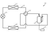
- FIG. 1 shows the refrigerant circuit 11 in the cooling operation.
- FIG. 2 shows the refrigerant circuit 11 in the heating operation.
- the refrigeration cycle apparatus 10 is an air conditioner in the present embodiment, but may be an apparatus other than an air conditioner such as a refrigerator or a heat pump cycle apparatus.
- the refrigeration cycle apparatus 10 includes a refrigerant circuit 11 in which a refrigerant circulates.
- the refrigeration cycle apparatus 10 includes a compressor 12, a four-way valve 13, a first heat exchanger 14 which is an outdoor heat exchanger, an expansion mechanism 15 which is an expansion valve, and a second heat exchanger which is an indoor heat exchanger. And 16.
- the compressor 12, the four-way valve 13, the first heat exchanger 14, the expansion mechanism 15, and the second heat exchanger 16 are connected to the refrigerant circuit 11.
- the compressor 12 compresses the refrigerant.
- the four-way valve 13 switches the flow direction of the refrigerant between the cooling operation and the heating operation.
- the first heat exchanger 14 operates as a condenser during the cooling operation, and dissipates the refrigerant compressed by the compressor 12. That is, the first heat exchanger 14 performs heat exchange using the refrigerant compressed by the compressor 12.
- the first heat exchanger 14 operates as an evaporator at the time of heating operation, performs heat exchange between outdoor air and the refrigerant expanded by the expansion mechanism 15, and heats the refrigerant.
- the expansion mechanism 15 expands the refrigerant that has dissipated heat in the condenser.
- the second heat exchanger 16 operates as a condenser during heating operation, and dissipates the refrigerant compressed by the compressor 12. That is, the second heat exchanger 16 performs heat exchange using the refrigerant compressed by the compressor 12.
- the second heat exchanger 16 operates as an evaporator during the cooling operation, performs heat exchange between room air and the refrigerant expanded by the expansion mechanism 15, and heats the refrigerant.
- the refrigeration cycle apparatus 10 further includes a controller 17.
- the control device 17 is, for example, a microcomputer. Although only the connection between the control device 17 and the compressor 12 is shown in FIGS. 1 and 2, the control device 17 includes not only the compressor 12 but also components other than the compressor 12 connected to the refrigerant circuit 11. It may be connected. The controller 17 monitors and controls the state of each component connected to the controller 17.
- an HFC refrigerant such as R32, R125, R134a, R407C or R410A is used.
- HFO-based refrigerants such as R1123, R1132 (E), R1132 (Z), R1132 a, R1141, R1234yf, R1234ze (E) or R1234ze (Z) are used.
- natural refrigerants such as R290 (propane), R600a (isobutane), R744 (carbon dioxide) or R717 (ammonia) are used.
- other refrigerants are used.
- a mixture of two or more of these refrigerants is used.
- HFC is an abbreviation of Hydrofluorocarbon.
- HFO is an abbreviation of Hydrofluoroolefin.
- FIG. 3 shows a longitudinal cross section of the compressor 12.
- the compressor 12 is a hermetic electric compressor in the present embodiment.
- the compressor 12 is specifically a single-cylinder rotary compressor, but may be a multi-cylinder rotary compressor, a scroll compressor or a reciprocating compressor.
- the compressor 12 includes a container 20, a compression mechanism 30, an electric motor 40, and a crankshaft 50.
- the container 20 is a closed container. At the bottom of the container 20, refrigeration oil 25 is stored. A suction pipe 21 for suctioning the refrigerant into the container 20 and a discharge pipe 22 for discharging the refrigerant to the outside of the container 20 are attached to the container 20.
- the motor 40 is housed in the container 20. Specifically, the motor 40 is installed at the upper inside of the container 20.
- the compression mechanism 30 is housed in the container 20. Specifically, the compression mechanism 30 is installed at the lower inside of the container 20. That is, the compression mechanism 30 is disposed below the motor 40 in the container 20.
- the crankshaft 50 connects the motor 40 and the compression mechanism 30.
- the crankshaft 50 forms an oil supply passage of the refrigerator oil 25 and a rotation shaft of the electric motor 40.
- the refrigeration oil 25 is pumped up by the oil supply mechanism such as an oil pump provided at the lower part of the crankshaft 50 as the crankshaft 50 rotates.
- the refrigeration oil 25 is supplied to the sliding parts of the compression mechanism 30 to lubricate the sliding parts of the compression mechanism 30.
- POE is an abbreviation of Polyolester.
- PVE is an abbreviation for Polyvinyl Ether.
- AB is an abbreviation of Alkylbenzene.
- the motor 40 rotates the crankshaft 50.
- the compression mechanism 30 is driven by the rotation of the crankshaft 50 to compress the refrigerant. That is, the compression mechanism 30 compresses the refrigerant by being driven by the rotational force of the electric motor 40 transmitted through the crankshaft 50. Specifically, this refrigerant is a low-pressure gas refrigerant sucked into the suction pipe 21. The high temperature and high pressure gas refrigerant compressed by the compression mechanism 30 is discharged from the compression mechanism 30 into the space in the container 20.
- the crankshaft 50 includes an eccentric shaft 51, a main shaft 52, and a countershaft 53. These are provided in the order of the main shaft 52, the eccentric shaft 51, and the auxiliary shaft 53 in the axial direction. That is, the main shaft portion 52 is provided on one end side in the axial direction of the eccentric shaft portion 51, and the sub shaft portion 53 is provided on the other end side in the axial direction of the eccentric shaft portion 51.
- the eccentric shaft portion 51, the main shaft portion 52, and the sub shaft portion 53 each have a cylindrical shape.
- the main shaft portion 52 and the sub shaft portion 53 are provided such that the central axes thereof coincide with each other, that is, coaxially.
- the eccentric shaft portion 51 is provided such that the central axis thereof is offset from the central axes of the main shaft portion 52 and the auxiliary shaft portion 53.
- the eccentric shaft portion 51 eccentrically rotates.
- the container 20 includes a body portion 20a, a container upper portion 20b, and a container lower portion 20c.
- the body 20a is cylindrical.
- the container upper part 20b is closing the upper opening of the trunk
- the container upper portion 20 b corresponds to one axial end of the container 20.
- the lower part 20c of the container is closing the lower opening of the body 20a.
- the container lower portion 20 c corresponds to the other axial end of the container 20.
- the body 20a and the container upper portion 20b are connected by welding, and the body 20a and the container lower portion 20c are connected by welding, whereby the container 20 is sealed.
- the body 20 a is provided with a suction pipe 21 connected to the suction muffler 23.
- a discharge pipe 22 is provided in the container upper portion 20b.
- a power supply terminal 24 connected to an external power supply such as an inverter device and a rod 26 to which a cover for protecting the power supply terminal 24 is attached are attached to the container upper portion 20b.
- the power supply terminal 24 is an airtight terminal such as a glass terminal.
- the power supply terminal 24 is fixed to the container 20 by welding.
- a discharge pipe 22 whose both ends in the axial direction are open is further attached to the container upper portion 20b.
- the discharge pipe 22 may be installed at the outer peripheral portion of the container upper portion 20b, but in the present embodiment, it is installed at the center of the container upper portion 20b just above the crankshaft 50.
- the outer diameter of the discharge pipe 22 is desirably 0.1 times or more and 0.2 times or less the outer diameter of the container upper portion 20b.
- FIG. 4 shows a cross-section of a portion of the compressor 12 as viewed along the axial direction.
- hatching representing a cross section is omitted.
- the compression mechanism 30 includes a cylinder 31, a rolling piston 32, a main bearing 33, an auxiliary bearing 34, and a discharge muffler 35.
- the inner periphery of the cylinder 31 is circular in plan view. Inside the cylinder 31, a cylinder chamber 61 which is a circular space in plan view is formed. A suction port for suctioning the gas refrigerant from the refrigerant circuit 11 is provided on the outer peripheral surface of the cylinder 31. The refrigerant drawn from the suction port is compressed in the cylinder chamber 61. Both ends in the axial direction of the cylinder 31 are open.
- the rolling piston 32 is ring-shaped. Therefore, the inner circumference and the outer circumference of the rolling piston 32 are circular in plan view.
- the rolling piston 32 rotates eccentrically in the cylinder chamber 61.
- the rolling piston 32 is slidably fitted on an eccentric shaft portion 51 of a crankshaft 50 which is a rotation shaft of the rolling piston 32.
- the cylinder 31 is provided with vane grooves 62 connected to the cylinder chamber 61 and extending in the radial direction.
- a back pressure chamber 63 which is a circular space in plan view connected to the vane groove 62 is formed.
- a vane 64 for separating the cylinder chamber 61 into a suction chamber, which is a low pressure operating chamber, and a compression chamber, which is a high pressure operating chamber is installed in the vane groove 62.
- the vanes 64 are in the form of a plate whose tip is rounded.
- the vanes 64 reciprocate while sliding in the vane grooves 62.
- the vanes 64 are always pressed against the rolling piston 32 by vane springs provided in the back pressure chamber 63.
- the vane spring is mainly used for the purpose of pressing the vane 64 against the rolling piston 32 when the compressor 12 starts with no difference in pressure in the container 20 and in the cylinder chamber 61.
- the main bearing 33 is a reverse T-shaped bearing in a side view.
- the main bearing 33 is slidably fitted on a main shaft portion 52 which is a portion above the eccentric shaft portion 51 of the crankshaft 50.
- a through hole 54 serving as an oil supply passage is provided along the axial direction inside the crankshaft 50, and between the main bearing 33 and the main shaft portion 52, the refrigeration sucked through the through hole 54.
- An oil film is formed by supplying the mechanical oil 25.
- the main bearing 33 closes the upper side of the cylinder chamber 61 and the vane groove 62 of the cylinder 31. That is, the main bearing 33 closes the upper side of the two working chambers in the cylinder 31.
- the auxiliary bearing 34 is a T-shaped bearing in a side view.
- the sub bearing 34 is slidably fitted in a sub shaft portion 53 which is a portion below the eccentric shaft portion 51 of the crankshaft 50.
- An oil film is formed between the sub bearing 34 and the sub shaft portion 53 by supplying the refrigerating machine oil 25 sucked up through the through hole 54 of the crankshaft 50.
- the sub bearing 34 closes the lower side of the cylinder chamber 61 and the vane groove 62 of the cylinder 31. That is, the sub bearing 34 closes the lower side of the two working chambers in the cylinder 31.
- the main bearing 33 and the sub bearing 34 are fixed to the cylinder 31 by fasteners 36 such as bolts, respectively, and support a crankshaft 50 which is a rotation shaft of the rolling piston 32.
- the main bearing 33 supports the main shaft 52 without contacting the main shaft 52 by fluid lubrication of the oil film between the main bearing 33 and the main shaft 52.
- the secondary bearing 34 supports the secondary shaft 53 without contacting the secondary shaft 53 by fluid lubrication of the oil film between the secondary bearing 34 and the secondary shaft 53 as the main bearing 33 does.
- the main bearing 33 is provided with a discharge port for discharging the refrigerant compressed in the cylinder chamber 61 to the refrigerant circuit 11.
- the discharge port is at a position where it is connected to the compression chamber when the cylinder chamber 61 is divided by the vane 64 into a suction chamber and a compression chamber.
- the main bearing 33 is attached with a discharge valve that closes the discharge port so as to open and close. The discharge valve is closed until the gas refrigerant in the compression chamber reaches a desired pressure, and is opened when the gas refrigerant in the compression chamber reaches a desired pressure. Thereby, the discharge timing of the gas refrigerant from the cylinder 31 is controlled.
- the discharge muffler 35 is attached to the outside of the main bearing 33.
- the high-temperature, high-pressure gas refrigerant discharged when the discharge valve is opened enters the discharge muffler 35 and is then discharged from the discharge muffler 35 into the space in the container 20.
- the discharge port and the discharge valve may be provided in the sub bearing 34 or both the main bearing 33 and the sub bearing 34.
- the discharge muffler 35 is attached to the outside of the bearing on which the discharge port and the discharge valve are provided.
- An intake muffler 23 is provided beside the container 20.
- the suction muffler 23 sucks the low-pressure gas refrigerant from the refrigerant circuit 11.
- the suction muffler 23 prevents the liquid refrigerant from directly entering the cylinder chamber 61 of the cylinder 31 when the liquid refrigerant returns.
- the suction muffler 23 is connected to a suction port provided on the outer peripheral surface of the cylinder 31 via a suction pipe 21.
- the suction port is in a position to be connected to the suction chamber when the cylinder chamber 61 is divided by the vane 64 into the suction chamber and the compression chamber.
- the main body of the suction muffler 23 is fixed to the side surface of the body 20 a of the container 20 by welding or the like.
- the material of the eccentric shaft portion 51, the main shaft portion 52 and the countershaft portion 53 of the crankshaft 50 is a cast material or a forged material.
- the material of the main bearing 33 and the auxiliary bearing 34 is a cast material or a sintered material, and specifically, sintered steel, gray cast iron or carbon steel.
- the material of the cylinder 31 is also sintered steel, gray cast iron or carbon steel.
- the material of the rolling piston 32 is a cast material, and specifically, an alloy steel containing molybdenum, nickel and chromium, or an iron-based cast material.
- the material of the vanes 64 is high speed tool steel.
- the vanes 64 are provided integrally with the rolling piston 32.
- the vanes 64 reciprocate along the grooves of a support rotatably mounted on the rolling piston 32.
- the vanes 64 radially advance and retract while oscillating as the rolling piston 32 rotates, thereby dividing the inside of the cylinder chamber 61 into a compression chamber and a suction chamber.
- the support is constituted by two columnar members having a semicircular cross section. The support is rotatably fitted in a circular holding hole formed at an intermediate portion between the suction port and the discharge port of the cylinder 31.
- the motor 40 is an induction motor in the present embodiment, but may be a motor other than an induction motor such as a brushless DC motor.
- DC is an abbreviation of Direct Current.
- the motor 40 includes a stator 41 and a rotor 42.
- the stator 41 is cylindrical and fixed so as to be in contact with the inner circumferential surface of the container 20.
- the rotor 42 has a cylindrical shape, and is installed inside the stator 41 with an air gap.
- the width of the air gap is, for example, 0.3 mm or more and 1.0 mm or less.
- the stator 41 includes a stator core 43, a winding 44 and a wire bundle 45.
- the stator core 43 is manufactured by punching a plurality of magnetic steel sheets containing iron as a main component into a predetermined shape, laminating them in the axial direction, and fixing them by caulking.
- the thickness of each electromagnetic steel sheet is, for example, 0.1 mm or more and 1.5 mm or less.
- the stator core 43 has an outer diameter larger than the inner diameter of the body 20 a of the container 20, and is fixed to the inside of the body 20 a of the container 20 by shrink fitting.
- the method of fixing the electromagnetic steel plates of the stator core 43 is not limited to caulking, and other methods such as welding may be used.
- the method of fixing the stator core 43 to the inside of the body portion 20a of the container 20 is not limited to shrink fitting, and may be another method such as press fitting or welding.
- the windings 44 are wound around a stator core 43. Specifically, the winding 44 is wound around teeth formed on the stator core 43 via an insulating member.
- the winding 44 comprises a core wire and at least one layer of coating covering the core wire.
- the winding 44 is electrically connected to the power supply terminal 24 by a wire bundle 45.
- the material of the core wire is copper.
- the material of the film is AI / EI.
- AI is an abbreviation of Amide-Imide.
- EI is an abbreviation of Ester-Imide.
- the material of the insulating member is PET.
- PET is an abbreviation for Polyethylene Terephthalate.
- the material of the core wire may be aluminum.
- the material of the insulating member may be PBT, FEP, PFA, PTFE, LCP, PPS or a phenol resin.
- PBT is an abbreviation for Polybutylene Terephthalate.
- FEP is an abbreviation for Fluorinated Ethylene Propylene.
- PFA is an abbreviation of Perfluoroalkoxy Alkane.
- PTFE is an abbreviation of Polytetrafluoroethylene.
- LCP is an abbreviation for Liquid Crystal Polymer.
- PPS is an abbreviation of Polyphenylene Sulfide.
- the wire bundle 45 is formed by bundling two or more wires. One end of the wire bundle 45 is electrically connected to the winding 44. The other end of the wire bundle 45 is electrically connected to the power supply terminal 24.
- Each wire of the wire bundle 45 may be a wire separate from the winding 44, but in the present embodiment, it is a wire integral with the winding 44. That is, each wire of the wire bundle 45 may be connected to the winding 44 via the connection terminal, but in the present embodiment, the end of the winding 44 is drawn out directly. Therefore, each wire of the wire bundle 45 includes the core wire and at least one layer of coating covering the core wire, similarly to the winding 44.
- the wire bundle 45 is formed by bundling three wires of a first outlet wire 71, a second outlet wire 72 and a third outlet wire 73. There is. These three wires have different potentials. Therefore, in order to ensure insulation, it is desirable that at least two electric wires be covered with the insulating tube 74.
- the first lead-out line 71 is a lead-out line of the common line.
- the second lead wire 72 is a lead wire of the main winding.
- the third lead wire 73 is a lead wire for the auxiliary winding.
- the first lead wire 71, the second lead wire 72, and the third lead wire 73 are each formed by directly pulling out the end of the winding 44. That is, in the present embodiment, one end of the wire bundle 45 is integrated with the winding 44.
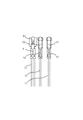
- the first lead wire 71, the second lead wire 72, and the third lead wire 73 are respectively crimped to the crimp terminals. Specifically, as shown in FIG. 6, the tips of the first outlet line 71, the second outlet line 72 and the third outlet line 73 are respectively the first crimp terminal 81, the second crimp terminal 82 and the second 3
- the crimped terminal 83 is crimped. That is, in the present embodiment, the other end of the wire bundle 45 is electrically connected to the power supply terminal 24 via the crimp terminal.
- the 1st crimp terminal 81, the 2nd crimp terminal 82, and the 3rd crimp terminal 83 are inserted in the cluster 46 which is a block-like molded article which consists of resin, such as PBT. Therefore, all crimp terminals can be connected to the power supply terminal 24 simply by connecting the cluster 46 to the power supply terminal 24, and the connection workability is improved.
- a plurality of notches may be formed on the outer periphery of the stator core 43 at equal intervals in the circumferential direction.
- Each notch becomes one of the passages of the gas refrigerant discharged from the discharge muffler 35 to the space in the container 20.
- Each notch also serves as one of the passages for dropping refrigerator oil 25 led to the upper part of the container 20 to the lower part of the container 20.
- the rotor 42 is an aluminum die-cast squirrel-cage rotor.
- the rotor 42 includes a rotor core 47, a conductor (not shown), and an end ring 48.
- the rotor core 47 is manufactured by punching a plurality of magnetic steel sheets containing iron as a main component into a predetermined shape, laminating them in the axial direction, and fixing them by caulking.
- the thickness of each electromagnetic steel sheet is, for example, 0.1 mm or more and 1.5 mm or less.
- the method of fixing the electromagnetic steel plates of the rotor core 47 is not limited to caulking, and other methods such as welding may be used.
- the conductor is formed of aluminum in the present embodiment, but may be formed of copper or the like.
- the conductors are filled or inserted into a plurality of slots formed in the rotor core 47.
- the end ring 48 shorts both ends of the conductor. Thus, a cage winding is formed.
- an axial hole is formed in which the main shaft portion 52 of the crankshaft 50 is shrink-fit or press-fitted. That is, the inner diameter of the rotor core 47 is smaller than the outer diameter of the main shaft portion 52.
- a plurality of through holes extending in the axial direction are formed around the axial hole of the rotor core 47. Each through hole is one of the passages of the gas refrigerant discharged from the discharge muffler 35 to the space in the container 20. Each through hole also serves as one of the passages for dropping the refrigerator oil 25 led to the upper part of the container 20 to the lower part of the container 20.
- the motor 40 when the motor 40 is configured as a brushless DC motor, permanent magnets are inserted into a plurality of insertion holes formed in the rotor core 47.
- the permanent magnet forms a magnetic pole.
- a permanent magnet a ferrite magnet or a rare earth magnet is used.
- Upper and lower end plates are provided at both axial ends of the rotor 42 in order to prevent the permanent magnets from coming off in the axial direction.
- the upper end plate and the lower end plate also serve as a rotary balancer.
- the upper end plate and the lower end plate are fixed to the rotor core 47 by a plurality of fixing rivets or the like.
- Electric power is supplied from the power supply terminal 24 to the stator 41 of the motor 40 via the wire bundle 45.
- current flows through the windings 44 of the stator 41, and magnetic flux is generated from the windings 44.
- the rotor 42 of the motor 40 is rotated by the action of the magnetic flux generated from the winding 44 and the magnetic flux generated from the cage winding of the rotor 42.
- the rotation of the rotor 42 causes the crankshaft 50 fixed to the rotor 42 to rotate.
- the rolling piston 32 of the compression mechanism 30 eccentrically rotates in the cylinder chamber 61 of the cylinder 31 of the compression mechanism 30.
- a cylinder chamber 61 which is a space between the cylinder 31 and the rolling piston 32 is divided by a vane 64 into a suction chamber and a compression chamber.
- the crankshaft 50 rotates, the volume of the suction chamber and the volume of the compression chamber change.
- the suction chamber the low-pressure gas refrigerant is sucked from the suction muffler 23 through the suction pipe 21 by gradually expanding the volume.
- the compression chamber the volume of the gas refrigerant is gradually reduced by gradually reducing the volume.
- the compressed, high-pressure and high-temperature gas refrigerant is discharged from the discharge muffler 35 into the space in the container 20.
- the discharged gas refrigerant further passes through the electric motor 40 and is discharged from the discharge pipe 22 in the container upper portion 20 b to the outside of the container 20.
- the refrigerant discharged out of the container 20 returns to the suction muffler 23 again through the refrigerant circuit 11.
- the wire bundle 45 of the stator 41 is formed by bundling three wires of the first lead wire 71, the second lead wire 72, and the third lead wire 73.
- One end of the wire bundle 45 is electrically connected to the winding 44.
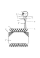
- the other end of the wire bundle 45 is electrically connected to the power supply terminal 24. As shown in FIG. 5, at least a part of the wire bundle 45 except for the other end is twisted.
- the first lead wire 71, the second lead wire 72, and the third lead wire 73 of the wire bundle 45 are each formed by directly pulling out the end of the winding 44.
- the portion from the lead wire fixing position P1 of the wire bundle 45 to the lead wire intermediate position P2 is twisted.
- the twisting direction may be clockwise or counterclockwise.
- the number of twisting rotations may be any number of rotations.
- the first lead wire 71, the second lead wire 72 and the third lead wire 73 of the wire bundle 45 are respectively connected to the first crimp terminal 81, the second crimp terminal 82 and the third crimp terminal 83. It is crimped.
- the first crimp terminal 81, the second crimp terminal 82, and the third crimp terminal 83 are housed inside the cluster 46.
- the first lead wire 71 extends straight in the direction of the winding 44 from the first terminal crimped portion 91 which is a portion crimped to the first crimp terminal 81.
- the second lead wire 72 extends straight in the direction of the winding 44 from the second terminal crimped portion 92 which is a portion crimped to the second crimp terminal 82.
- the third lead wire 73 extends straight in the direction of the winding 44 from a third terminal crimped portion 93 which is a portion crimped to the third crimp terminal 83.
- the first lead wire 71, the second lead wire 72 and the third lead wire 73 are respectively directed from the first terminal caulking portion 91, the second terminal caulking portion 92 and the third terminal caulking portion 93 in the direction of the winding 44 It is desirable to extend straight 15 mm or more.
- the lead wire of the wire bundle 45 is unlikely to be separated, and the lead wire is easily routed. Become.
- the workability of the process of connecting the cluster 46 to the power supply terminal 24 is improved, and the lead wire can be reliably prevented from contacting the container 20 or the rotor 42 of the compressor 12.
- the part by which the lead wire is crimped to the crimp terminal is not twisted, sufficient tensile strength and bending strength of the said part are securable.
- the end of the winding 44 of the motor 40 is directly drawn out to form a lead wire, and an insulation tube covering the crimp terminal for connection to the power supply terminal 24 and the lead portion at the tip of the lead wire. 74 are attached, and after the lead wire is twisted from the lead wire fixing position P1 to the lead wire intermediate position P2, wire connection is performed in the procedure of connecting the crimp terminal to the power supply terminal 24.
- the portion crimped to the crimp terminal of the lead wire is not twisted and is straight, so that the lead wire serves as the container 20 or the rotor of the compressor 12 at the time of connection while sufficiently securing the tensile strength and bending strength of the portion. 42 can be prevented from contacting. Therefore, both the wire connection efficiency and the reliability of the compressor 12 are improved.
- the first lead wire 71, the second lead wire 72, and the third lead wire 73 may be single or plural.
- the lead wires of the winding 44 and the wire bundle 45 may be either copper wires or aluminum wires. That is, although each lead wire of the wire bundle 45 is a copper wire in the present embodiment, at least one lead wire may be an aluminum wire, and all lead wires may be aluminum wires.
- the aluminum wire is softer than the copper wire and has lower tensile strength and flexural strength, so it is effective to apply the present embodiment.
- the body portion 20a and the container lower portion 20c of the container 20 are connected by welding, but as a modification, the body portion 20a and the container lower portion 20c of the container 20 may be integrally formed.
Abstract
固定子(41)の電線束(45)は、第1口出線(71)、第2口出線(72)および第3口出線(73)の3本の電線が束ねられて形成されている。電線束(45)の第1口出線(71)、第2口出線(72)および第3口出線(73)は、それぞれ巻線(44)の端部が直に引き出されて形成されている。電線束(45)の口出線固定位置(P1)から口出線中間位置(P2)までの部分は捻られている。電線束(45)の第1口出線(71)、第2口出線(72)および第3口出線(73)の先端は、それぞれ圧着端子にかしめられている。圧着端子は、クラスタ(46)の内部に収納されている。クラスタ(46)は、圧縮機の電源端子に接続される。
Description
本発明は、電動機、圧縮機および冷凍サイクル装置に関するものである。
特許文献1に記載の圧縮機では、モータ固定子の巻線の端部を延伸して形成された口出線の先端が圧着端子にかしめられ、この圧着端子に嵌るナットの間に給電用の接続端子を挟み込んで固定することでモータ固定子に電力が供給される。
口出線は軟らかく、変形しやすいため、ケーシングまたはモータ回転子に接触しやすい。口出線の絶縁被膜は薄く、絶縁性が低いため、口出線がケーシングまたはモータ回転子に接触すると絶縁不良が起こる。
口出線の圧着端子にかしめられた部分は機械強度が弱いため、ナットを嵌める際、あるいは、給電用の接続端子を固定する際に捻れていると断線しやすい。
本発明は、電動機の巻線と圧縮機の電源端子とを電気的に接続する電線束の電源端子に接続される部分の強度を確保しつつ、電線束が圧縮機の容器または回転子に接触することを防止できるようにすることを目的とする。
本発明の一態様に係る電動機は、
圧縮機の容器に収容して使用され、
巻線と、
2本以上の電線が束ねられて形成され、一端が前記巻線に電気接続され、他端が前記圧縮機の電源端子に電気接続され、前記他端を除く部分の少なくとも一部が捻られている電線束と
を備える。
圧縮機の容器に収容して使用され、
巻線と、
2本以上の電線が束ねられて形成され、一端が前記巻線に電気接続され、他端が前記圧縮機の電源端子に電気接続され、前記他端を除く部分の少なくとも一部が捻られている電線束と
を備える。
本発明では、電動機の巻線と圧縮機の電源端子とを電気的に接続する電線束の、電源端子に接続される側の端を除く部分の少なくとも一部が捻られている。そのため、電線束の電源端子に接続される部分の強度を確保しつつ、電線束が圧縮機の容器または回転子に接触することを防止できる。
以下、本発明の実施の形態について、図を用いて説明する。各図中、同一または相当する部分には、同一符号を付している。実施の形態の説明において、同一または相当する部分については、説明を適宜省略または簡略化する。なお、本発明は、以下に説明する実施の形態に限定されるものではなく、必要に応じて種々の変更が可能である。例えば、以下に説明する実施の形態は、部分的に実施されても構わない。
実施の形態1.
本実施の形態について、図1から図6を用いて説明する。
本実施の形態について、図1から図6を用いて説明する。
***構成の説明***
図1および図2を参照して、本実施の形態に係る冷凍サイクル装置10の構成を説明する。
図1および図2を参照して、本実施の形態に係る冷凍サイクル装置10の構成を説明する。
図1は、冷房運転時の冷媒回路11を示している。図2は、暖房運転時の冷媒回路11を示している。
冷凍サイクル装置10は、本実施の形態では空気調和機であるが、冷蔵庫またはヒートポンプサイクル装置といった空気調和機以外の装置であってもよい。
冷凍サイクル装置10は、冷媒が循環する冷媒回路11を備える。冷凍サイクル装置10は、圧縮機12と、四方弁13と、室外熱交換器である第1熱交換器14と、膨張弁である膨張機構15と、室内熱交換器である第2熱交換器16とをさらに備える。圧縮機12、四方弁13、第1熱交換器14、膨張機構15および第2熱交換器16は、冷媒回路11に接続されている。
圧縮機12は、冷媒を圧縮する。四方弁13は、冷房運転時と暖房運転時とで冷媒の流れる方向を切り換える。第1熱交換器14は、冷房運転時には凝縮器として動作し、圧縮機12により圧縮された冷媒を放熱させる。すなわち、第1熱交換器14は、圧縮機12により圧縮された冷媒を用いて熱交換を行う。第1熱交換器14は、暖房運転時には蒸発器として動作し、室外空気と膨張機構15で膨張した冷媒との間で熱交換を行って冷媒を加熱する。膨張機構15は、凝縮器で放熱した冷媒を膨張させる。第2熱交換器16は、暖房運転時には凝縮器として動作し、圧縮機12により圧縮された冷媒を放熱させる。すなわち、第2熱交換器16は、圧縮機12により圧縮された冷媒を用いて熱交換を行う。第2熱交換器16は、冷房運転時には蒸発器として動作し、室内空気と膨張機構15で膨張した冷媒との間で熱交換を行って冷媒を加熱する。
冷凍サイクル装置10は、制御装置17をさらに備える。
制御装置17は、例えば、マイクロコンピュータである。図1および図2では、制御装置17と圧縮機12との接続しか示していないが、制御装置17は、圧縮機12だけでなく、冷媒回路11に接続された圧縮機12以外の構成要素に接続されてもよい。制御装置17は、制御装置17に接続されている各構成要素の状態を監視したり、制御したりする。
冷媒回路11を循環する冷媒としては、R32、R125、R134a、R407CまたはR410AといったHFC系冷媒が使用される。あるいは、R1123、R1132(E)、R1132(Z)、R1132a、R1141、R1234yf、R1234ze(E)またはR1234ze(Z)といったHFO系冷媒が使用される。あるいは、R290(プロパン)、R600a(イソブタン)、R744(二酸化炭素)またはR717(アンモニア)といった自然冷媒が使用される。あるいは、その他の冷媒が使用される。あるいは、これらの冷媒のうち2種類以上の混合物が使用される。「HFC」は、Hydrofluorocarbonの略語である。「HFO」は、Hydrofluoroolefinの略語である。
図3を参照して、本実施の形態に係る圧縮機12の構成を説明する。
図3は、圧縮機12の縦断面を示している。
圧縮機12は、本実施の形態では密閉型電動圧縮機である。圧縮機12は、具体的には、単シリンダのロータリ圧縮機であるが、多シリンダのロータリ圧縮機、スクロール圧縮機またはレシプロ圧縮機であってもよい。
圧縮機12は、容器20と、圧縮機構30と、電動機40と、クランク軸50とを備える。
容器20は、具体的には、密閉容器である。容器20の底部には、冷凍機油25が貯留されている。容器20には、冷媒を容器20の中に吸入するための吸入管21と、冷媒を容器20の外に吐出するための吐出管22とが取り付けられている。
電動機40は、容器20に収容されている。具体的には、電動機40は、容器20の内側上部に設置されている。
圧縮機構30は、容器20に収容されている。具体的には、圧縮機構30は、容器20の内側下部に設置されている。すなわち、圧縮機構30は、容器20内で電動機40の下方に配置されている。
クランク軸50は、電動機40と圧縮機構30とを連結している。クランク軸50は、冷凍機油25の給油路と電動機40の回転軸とを形成している。
冷凍機油25は、クランク軸50の回転に伴い、クランク軸50の下部に設けられたオイルポンプ等の給油機構によって汲み上げられる。そして、冷凍機油25は、圧縮機構30の各摺動部へ供給され、圧縮機構30の各摺動部を潤滑する。冷凍機油25としては、合成油であるPOE、PVEまたはAB等が使用される。「POE」は、Polyolesterの略語である。「PVE」は、Polyvinyl Etherの略語である。「AB」は、Alkylbenzeneの略語である。
電動機40は、クランク軸50を回転させる。圧縮機構30は、クランク軸50の回転によって駆動されることで冷媒を圧縮する。すなわち、圧縮機構30は、クランク軸50を介して伝達される電動機40の回転力によって駆動されることで冷媒を圧縮する。この冷媒は、具体的には、吸入管21に吸入された低圧のガス冷媒である。圧縮機構30で圧縮された高温かつ高圧のガス冷媒は、圧縮機構30から容器20内の空間に吐出される。
クランク軸50は、偏心軸部51と、主軸部52と、副軸部53とを備える。これらは、軸方向において主軸部52、偏心軸部51、副軸部53の順に設けられている。すなわち、偏心軸部51の軸方向一端側に主軸部52、偏心軸部51の軸方向他端側に副軸部53が設けられている。偏心軸部51、主軸部52および副軸部53は、それぞれ円柱状である。主軸部52および副軸部53は、互いの中心軸が一致するように、すなわち、同軸に設けられている。偏心軸部51は、中心軸が主軸部52および副軸部53の中心軸からずれるように設けられている。主軸部52および副軸部53が中心軸周りに回転すると、偏心軸部51は偏心回転する。
以下では、容器20の詳細を説明する。
容器20は、胴部20aと、容器上部20bと、容器下部20cとを備える。
胴部20aは、円筒状である。容器上部20bは、胴部20aの上側の開口を塞いでいる。容器上部20bは、容器20の軸方向一端に相当する。容器下部20cは、胴部20aの下側の開口を塞いでいる。容器下部20cは、容器20の軸方向他端に相当する。胴部20aと容器上部20bとが溶接により連結され、胴部20aと容器下部20cとが溶接により連結されることで、容器20は密閉されている。胴部20aには、吸入マフラ23に接続される吸入管21が設けられている。容器上部20bには、吐出管22が設けられている。
容器上部20bには、インバータ装置等の外部電源と接続する電源端子24と、電源端子24を保護するためのカバーが取り付けられるロッド26とが取り付けられている。電源端子24は、具体的には、ガラス端子等の気密端子である。本実施の形態において、電源端子24は、溶接により容器20に固定されている。
容器上部20bには、軸方向両端が開口した吐出管22がさらに取り付けられている。吐出管22は、容器上部20bの外周部に設置されてもよいが、本実施の形態では、クランク軸50の真上で、容器上部20bの中央部に設置されている。吐出管22の外径は、容器上部20bの外径の0.1倍以上0.2倍以下であることが望ましい。
以下では、図3だけでなく図4も参照して、圧縮機構30の詳細を説明する。
図4は、軸方向に沿って見た圧縮機12の一部の横断面を示している。なお、図4において、断面を表すハッチングは省略している。
圧縮機構30は、シリンダ31と、ローリングピストン32と、主軸受33と、副軸受34と、吐出マフラ35とを備える。
シリンダ31の内周は、平面視円形である。シリンダ31の内部には、平面視円形の空間であるシリンダ室61が形成されている。シリンダ31の外周面には、冷媒回路11からガス冷媒を吸入するための吸入口が設けられている。吸入口から吸入された冷媒は、シリンダ室61で圧縮される。シリンダ31は、軸方向両端が開口している。
ローリングピストン32は、リング状である。よって、ローリングピストン32の内周および外周は、平面視円形である。ローリングピストン32は、シリンダ室61内で偏心回転する。ローリングピストン32は、ローリングピストン32の回転軸となるクランク軸50の偏心軸部51に摺動自在に嵌められている。
シリンダ31には、シリンダ室61につながり、半径方向に延びるベーン溝62が設けられている。ベーン溝62の外側には、ベーン溝62につながる平面視円形の空間である背圧室63が形成されている。ベーン溝62内には、シリンダ室61を低圧の作動室である吸入室と高圧の作動室である圧縮室とに仕切るためのベーン64が設置されている。ベーン64は、先端が丸まった板状である。ベーン64は、ベーン溝62内で摺動しながら往復運動する。ベーン64は、背圧室63に設けられたベーンスプリングによって常にローリングピストン32に押し付けられている。容器20内が高圧であるため、圧縮機12の運転が開始すると、ベーン64の背圧室63側の面であるベーン背面に容器20内の圧力とシリンダ室61内の圧力との差による力が作用する。このため、ベーンスプリングは、主に容器20内とシリンダ室61内の圧力に差がない圧縮機12の起動時に、ベーン64をローリングピストン32に押し付ける目的で使用される。
主軸受33は、側面視逆T字状の軸受である。主軸受33は、クランク軸50の偏心軸部51よりも上の部分である主軸部52に摺動自在に嵌められている。クランク軸50の内部には、給油路となる貫通孔54が軸方向に沿って設けられており、主軸受33と主軸部52との間には、この貫通孔54を介して吸い上げられた冷凍機油25が供給されることで油膜が形成されている。主軸受33は、シリンダ31のシリンダ室61およびベーン溝62の上側を閉塞している。すなわち、主軸受33は、シリンダ31内の2つの作動室の上側を閉塞している。
副軸受34は、側面視T字状の軸受である。副軸受34は、クランク軸50の偏心軸部51よりも下の部分である副軸部53に摺動自在に嵌められている。副軸受34と副軸部53との間には、クランク軸50の貫通孔54を介して吸い上げられた冷凍機油25が供給されることで油膜が形成されている。副軸受34は、シリンダ31のシリンダ室61およびベーン溝62の下側を閉塞している。すなわち、副軸受34は、シリンダ31内の2つの作動室の下側を閉塞している。
主軸受33と副軸受34は、それぞれボルト等の締結具36によってシリンダ31に固定され、ローリングピストン32の回転軸であるクランク軸50を支持している。主軸受33は、主軸受33と主軸部52との間の油膜の流体潤滑によって主軸部52に接触せずに主軸部52を支持している。副軸受34は、主軸受33と同様に、副軸受34と副軸部53との間の油膜の流体潤滑によって副軸部53に接触せずに副軸部53を支持している。
図示していないが、主軸受33には、シリンダ室61で圧縮された冷媒を冷媒回路11に吐出するための吐出口が設けられている。吐出口は、シリンダ室61がベーン64によって吸入室と圧縮室とに仕切られているときに圧縮室につながる位置にある。主軸受33には、吐出口を開閉自在に閉塞する吐出弁が取り付けられている。吐出弁は、圧縮室内のガス冷媒が所望の圧力になるまで閉じ、圧縮室内のガス冷媒が所望の圧力になると開く。これにより、シリンダ31からのガス冷媒の吐出タイミングが制御される。
吐出マフラ35は、主軸受33の外側に取り付けられている。吐出弁が開いたときに吐出される高温かつ高圧のガス冷媒は、一旦吐出マフラ35に入り、その後吐出マフラ35から容器20内の空間に放出される。
なお、吐出口および吐出弁は、副軸受34、あるいは、主軸受33と副軸受34との両方に設けられていてもよい。吐出マフラ35は、吐出口および吐出弁が設けられている軸受の外側に取り付けられる。
容器20の横には、吸入マフラ23が設けられている。吸入マフラ23は、冷媒回路11から低圧のガス冷媒を吸入する。吸入マフラ23は、液冷媒が戻る場合に液冷媒が直接シリンダ31のシリンダ室61に入り込むことを抑制する。吸入マフラ23は、シリンダ31の外周面に設けられた吸入口に吸入管21を介して接続されている。吸入口は、シリンダ室61がベーン64によって吸入室と圧縮室とに仕切られているときに吸入室につながる位置にある。吸入マフラ23の本体は、溶接等により容器20の胴部20aの側面に固定されている。
クランク軸50の偏心軸部51、主軸部52および副軸部53の材質は、鋳造材または鍛造材である。主軸受33および副軸受34の材質は、鋳造材または焼結材であり、具体的には、焼結鋼、ねずみ鋳鉄または炭素鋼である。シリンダ31の材質も、焼結鋼、ねずみ鋳鉄または炭素鋼である。ローリングピストン32の材質は、鋳造材であり、具体的には、モリブデン、ニッケルおよびクロムを含有する合金鋼、または、鉄系鋳造材である。ベーン64の材質は、高速度工具鋼である。
図示していないが、圧縮機12がスイング式のロータリ圧縮機として構成される場合には、ベーン64が、ローリングピストン32と一体に設けられる。クランク軸50が駆動されると、ベーン64は、ローリングピストン32に回転自在に取り付けられた支持体の溝に沿って往復運動する。ベーン64は、ローリングピストン32の回転に従って揺動しながら半径方向へ進退することによって、シリンダ室61の内部を圧縮室と吸入室とに区画する。支持体は、横断面が半円形状の2個の柱状部材で構成される。支持体は、シリンダ31の吸入口と吐出口との中間部に形成された円形状の保持孔に回転自在に嵌められる。
以下では、電動機40の詳細を説明する。
電動機40は、本実施の形態では誘導電動機であるが、ブラシレスDCモータ等、誘導電動機以外のモータであってもよい。「DC」は、Direct Currentの略語である。
電動機40は、固定子41と、回転子42とを備える。
固定子41は、円筒状であり、容器20の内周面に接するように固定されている。回転子42は、円柱状であり、固定子41の内側に空隙を介して設置されている。空隙の幅は、例えば、0.3mm以上1.0mm以下である。
固定子41は、固定子鉄心43と、巻線44と、電線束45とを備える。
固定子鉄心43は、鉄を主成分とする複数枚の電磁鋼板を一定の形状に打ち抜き、軸方向に積層し、カシメにより固定して製作される。各電磁鋼板の厚さは、例えば、0.1mm以上1.5mm以下である。固定子鉄心43は、外径が容器20の胴部20aの内径よりも大きく、容器20の胴部20aの内側に焼き嵌めにより固定されている。
なお、固定子鉄心43の電磁鋼板同士を固定する方法は、カシメに限らず、溶接等、他の方法であってもよい。固定子鉄心43を容器20の胴部20aの内側に固定する方法は、焼き嵌めに限らず、圧入または溶接等、他の方法であってもよい。
巻線44は、固定子鉄心43に巻かれている。具体的には、巻線44は、固定子鉄心43に形成されたティースに絶縁部材を介して巻かれている。巻線44は、芯線と、芯線を覆う少なくとも一層の被膜とからなる。巻線44は、電線束45によって電源端子24と電気的に接続されている。本実施の形態において、芯線の材質は、銅である。被膜の材質は、AI/EIである。「AI」は、Amide-Imideの略語である。「EI」は、Ester-Imideの略語である。絶縁部材の材質は、PETである。「PET」は、Polyethylene Terephthalateの略語である。
なお、芯線の材質は、アルミニウムであってもよい。絶縁部材の材質は、PBT、FEP、PFA、PTFE、LCP、PPSまたはフェノール樹脂であってもよい。「PBT」は、Polybutylene Terephthalateの略語である。「FEP」は、Fluorinated Ethylene Propyleneの略語である。「PFA」は、Perfluoroalkoxy Alkaneの略語である。「PTFE」は、Polytetrafluoroethyleneの略語である。「LCP」は、Liquid Crystal Polymerの略語である。「PPS」は、Polyphenylene Sulfideの略語である。
電線束45は、2本以上の電線が束ねられて形成されている。電線束45の一端は、巻線44に電気的に接続されている。電線束45の他端は、電源端子24に電気的に接続されている。電線束45の各電線は、巻線44とは別個の電線でもよいが、本実施の形態では巻線44と一体の電線である。すなわち、電線束45の各電線は、接続端子を介して巻線44に接続されていてもよいが、本実施の形態では巻線44の端部が直に引き出されて形成されている。よって、電線束45の各電線は、巻線44と同じように、芯線と、芯線を覆う少なくとも一層の被膜とからなる。
本実施の形態では、図5に示すように、電線束45は、第1口出線71、第2口出線72および第3口出線73の3本の電線が束ねられて形成されている。これら3本の電線は互いに電位が異なる。よって、絶縁性を確保するために、少なくとも2本の電線が絶縁チューブ74で覆われていることが望ましい。第1口出線71は、共通線の口出線である。第2口出線72は、主巻線の口出線である。第3口出線73は、補助巻線の口出線である。
第1口出線71、第2口出線72および第3口出線73は、それぞれ巻線44の端部が直に引き出されて形成されている。すなわち、本実施の形態では、電線束45の一端が巻線44と一体になっている。第1口出線71、第2口出線72および第3口出線73は、それぞれ圧着端子にかしめられている。具体的には、図6に示すように、第1口出線71、第2口出線72および第3口出線73の先端が、それぞれ第1圧着端子81、第2圧着端子82および第3圧着端子83にかしめられている。すなわち、本実施の形態では、電線束45の他端が圧着端子を介して電源端子24に電気的に接続されている。
第1圧着端子81、第2圧着端子82および第3圧着端子83は、PBT等の樹脂からなるブロック状の成形品であるクラスタ46に挿入されている。そのため、クラスタ46を電源端子24に接続するだけで、すべての圧着端子を電源端子24に接続することができ、結線作業性が向上する。
固定子鉄心43の外周には、周方向に等間隔に複数の切欠が形成されていてもよい。それぞれの切欠は、吐出マフラ35から容器20内の空間へ放出されるガス冷媒の通路の1つになる。それぞれの切欠は、容器20の上部に導かれた冷凍機油25を容器20の下部に落とすための通路の1つにもなる。
回転子42は、アルミダイキャスト製のかご形ロータである。
回転子42は、回転子鉄心47と、図示していない導体と、エンドリング48とを備える。
回転子鉄心47は、固定子鉄心43と同じように、鉄を主成分とする複数枚の電磁鋼板を一定の形状に打ち抜き、軸方向に積層し、カシメにより固定して製作される。各電磁鋼板の厚さは、例えば、0.1mm以上1.5mm以下である。
なお、回転子鉄心47の電磁鋼板同士を固定する方法は、カシメに限らず、溶接等、他の方法であってもよい。
導体は、本実施の形態ではアルミニウムで形成されているが、銅等で形成されていてもよい。導体は、回転子鉄心47に形成された複数個のスロットに充填または挿入されている。
エンドリング48は、導体の両端を短絡している。これにより、かご形巻線が形成されている。
回転子鉄心47の平面視中心には、クランク軸50の主軸部52が焼き嵌めまたは圧入される軸孔が形成されている。すなわち、回転子鉄心47の内径は、主軸部52の外径よりも小さくなっている。図示していないが、回転子鉄心47の軸孔の周囲には、軸方向に貫通する複数個の貫通孔が形成されている。それぞれの貫通孔は、吐出マフラ35から容器20内の空間へ放出されるガス冷媒の通路の1つになる。それぞれの貫通孔は、容器20の上部に導かれた冷凍機油25を容器20の下部に落とすための通路の1つにもなる。
図示していないが、電動機40がブラシレスDCモータとして構成される場合には、回転子鉄心47に形成される複数個の挿入孔に永久磁石が挿入される。永久磁石は、磁極を形成する。永久磁石としては、フェライト磁石または希土類磁石が使用される。永久磁石が軸方向に抜けないようにするために、回転子42の軸方向両端には、上端板および下端板が設けられる。上端板および下端板は、回転バランサを兼ねる。上端板および下端板は、複数の固定用リベット等により回転子鉄心47に固定される。
***動作の説明***
図3および図4を参照して、本実施の形態に係る圧縮機12の動作を説明する。圧縮機12の動作は、本実施の形態に係る冷媒圧縮方法に相当する。
図3および図4を参照して、本実施の形態に係る圧縮機12の動作を説明する。圧縮機12の動作は、本実施の形態に係る冷媒圧縮方法に相当する。
電源端子24から電線束45を介して電動機40の固定子41に電力が供給される。これにより、固定子41の巻線44に電流が流れ、巻線44から磁束が発生する。電動機40の回転子42は、巻線44から発生する磁束と、回転子42のかご形巻線から発生する磁束との作用によって回転する。回転子42の回転によって、回転子42に固定されたクランク軸50が回転する。クランク軸50の回転に伴い、圧縮機構30のローリングピストン32が圧縮機構30のシリンダ31のシリンダ室61内で偏心回転する。シリンダ31とローリングピストン32との間の空間であるシリンダ室61は、ベーン64によって吸入室と圧縮室とに分割されている。クランク軸50の回転に伴い、吸入室の容積と圧縮室の容積とが変化する。吸入室では、徐々に容積が拡大することにより、吸入マフラ23から吸入管21を介して低圧のガス冷媒が吸入される。圧縮室では、徐々に容積が縮小することにより、中のガス冷媒が圧縮される。圧縮され、高圧かつ高温となったガス冷媒は、吐出マフラ35から容器20内の空間に吐出される。吐出されたガス冷媒は、さらに、電動機40を通過して容器上部20bにある吐出管22から容器20の外へ吐出される。容器20の外へ吐出された冷媒は、冷媒回路11を通って、再び吸入マフラ23に戻ってくる。
***構成の詳細の説明***
図3、図5および図6を参照して、本実施の形態に係る圧縮機12の構成の詳細を説明する。
図3、図5および図6を参照して、本実施の形態に係る圧縮機12の構成の詳細を説明する。
前述したように、固定子41の電線束45は、第1口出線71、第2口出線72および第3口出線73の3本の電線が束ねられて形成されている。電線束45の一端は、巻線44に電気的に接続されている。電線束45の他端は、電源端子24に電気的に接続されている。図5に示すように、電線束45の、他端を除く部分の少なくとも一部は捻られている。
前述したように、電線束45の第1口出線71、第2口出線72および第3口出線73は、それぞれ巻線44の端部が直に引き出されて形成されている。図5に示すように、電線束45の口出線固定位置P1から口出線中間位置P2までの部分は捻られている。捻り方向は時計方向でも反時計方向でもよい。捻り回転数も任意の回転数でよい。
前述したように、電線束45の第1口出線71、第2口出線72および第3口出線73は、それぞれ第1圧着端子81、第2圧着端子82および第3圧着端子83にかしめられている。第1圧着端子81、第2圧着端子82および第3圧着端子83は、クラスタ46の内部に収納されている。
図6に示すように、第1口出線71は、第1圧着端子81にかしめられている部分である第1端子かしめ部91から巻線44の方向に真っ直ぐ延びている。第2口出線72は、第2圧着端子82にかしめられている部分である第2端子かしめ部92から巻線44の方向に真っ直ぐ延びている。第3口出線73は、第3圧着端子83にかしめられている部分である第3端子かしめ部93から巻線44の方向に真っ直ぐ延びている。第1口出線71、第2口出線72および第3口出線73は、それぞれ第1端子かしめ部91、第2端子かしめ部92および第3端子かしめ部93から巻線44の方向に15mm以上真っ直ぐ延びていることが望ましい。
***実施の形態の効果の説明***
本実施の形態では、電動機40の巻線44と圧縮機12の電源端子24とを電気的に接続する電線束45の、電源端子24に接続される側の端を除く部分の少なくとも一部が捻られている。そのため、電線束45の電源端子24に接続される部分の強度を確保しつつ、電線束45が圧縮機12の容器20または回転子42に接触することを防止できる。
本実施の形態では、電動機40の巻線44と圧縮機12の電源端子24とを電気的に接続する電線束45の、電源端子24に接続される側の端を除く部分の少なくとも一部が捻られている。そのため、電線束45の電源端子24に接続される部分の強度を確保しつつ、電線束45が圧縮機12の容器20または回転子42に接触することを防止できる。
本実施の形態では、電線束45が口出線固定位置P1から口出線中間位置P2まで捻じられることで、電線束45の口出線がばらばらになりにくく、口出線の取り回しが容易になる。その結果、電源端子24にクラスタ46を接続する工程の作業性が向上するとともに、口出線が圧縮機12の容器20または回転子42に接触することを確実に回避できる。しかも、口出線が圧着端子にかしめられている部分は捻じられないため、当該部分の引っ張り強度および曲げ強度を十分確保することができる。
本実施の形態では、電動機40の巻線44の端部を直に引き出して口出線とし、口出線の先端に、電源端子24に接続するための圧着端子と口出部分を覆う絶縁チューブ74とを取り付け、口出線固定位置P1から口出線中間位置P2にかけて口出線を捻った後、圧着端子を電源端子24に接続するという手順で結線が行われる。口出線の圧着端子にかしめられた部分は捻じられず、真っ直ぐであるため、当該部分の引っ張り強度および曲げ強度を十分確保しつつ、結線時に口出線が圧縮機12の容器20または回転子42に接触することを防止できる。したがって、結線の作業性と圧縮機12の信頼性との両方が向上する。
なお、第1口出線71、第2口出線72および第3口出線73は、いずれも単線でも複数線でもよい。
巻線44および電線束45の各口出線は、銅線およびアルミニウム線のどちらでもよい。すなわち、電線束45の各口出線は、本実施の形態では銅線であるが、少なくとも1本の口出線をアルミニウム線としてもよく、すべての口出線をアルミニウム線としてもよい。アルミニウム線は銅線に比べて軟らかく、引っ張り強度および曲げ強度が弱いため、本実施の形態を適用すると効果的である。
***他の構成***
本実施の形態では、容器20の胴部20aと容器下部20cとが溶接により連結されているが、変形例として、容器20の胴部20aと容器下部20cとが一体成形されていてもよい。
本実施の形態では、容器20の胴部20aと容器下部20cとが溶接により連結されているが、変形例として、容器20の胴部20aと容器下部20cとが一体成形されていてもよい。
10 冷凍サイクル装置、11 冷媒回路、12 圧縮機、13 四方弁、14 第1熱交換器、15 膨張機構、16 第2熱交換器、17 制御装置、20 容器、20a 胴部、20b 容器上部、20c 容器下部、21 吸入管、22 吐出管、23 吸入マフラ、24 電源端子、25 冷凍機油、26 ロッド、30 圧縮機構、31 シリンダ、32 ローリングピストン、33 主軸受、34 副軸受、35 吐出マフラ、36 締結具、40 電動機、41 固定子、42 回転子、43 固定子鉄心、44 巻線、45 電線束、46 クラスタ、47 回転子鉄心、48 エンドリング、50 クランク軸、51 偏心軸部、52 主軸部、53 副軸部、54 貫通孔、61 シリンダ室、62 ベーン溝、63 背圧室、64 ベーン、71 第1口出線、72 第2口出線、73 第3口出線、74 絶縁チューブ、81 第1圧着端子、82 第2圧着端子、83 第3圧着端子、91 第1端子かしめ部、92 第2端子かしめ部、93 第3端子かしめ部、P1 口出線固定位置、P2 口出線中間位置。
Claims (10)
- 圧縮機の容器に収容して使用される電動機において、
巻線と、
2本以上の電線が束ねられて形成され、一端が前記巻線に電気接続され、他端が前記圧縮機の電源端子に電気接続され、前記他端を除く部分の少なくとも一部が捻られている電線束と
を備える電動機。 - 前記電線束の各電線は、前記巻線の端部が直に引き出されて形成され、
前記電線束の前記一端は、前記巻線と一体になっている請求項1に記載の電動機。 - 前記電線束の各電線は、圧着端子にかしめられ、
前記電線束の前記他端は、前記圧着端子を介して前記電源端子に電気接続される請求項1または2に記載の電動機。 - 前記電線束の各電線は、前記圧着端子にかしめられている部分から前記巻線の方向に真っ直ぐ延び、途中から捻られている請求項3に記載の電動機。
- 前記電線束の各電線は、前記圧着端子にかしめられている部分から15mm以上真っ直ぐ延びている請求項4に記載の電動機。
- 前記電線束の各電線は、銅線である請求項1から5のいずれか1項に記載の電動機。
- 前記電線束の少なくとも1本の電線は、アルミニウム線である請求項1から5のいずれか1項に記載の電動機。
- 前記電線束の各電線は、アルミニウム線である請求項1から5のいずれか1項に記載の電動機。
- 請求項1から8のいずれか1項に記載の電動機と、
前記電動機により駆動されて冷媒を圧縮する圧縮機構と、
前記電動機と前記圧縮機構とを収容する容器と、
前記容器に固定され、前記電線束の前記他端に電気接続された電源端子と
を備える圧縮機。 - 請求項9に記載の圧縮機を備える冷凍サイクル装置。
Priority Applications (3)
| Application Number | Priority Date | Filing Date | Title |
|---|---|---|---|
| CN201780097016.0A CN111357172A (zh) | 2017-11-24 | 2017-11-24 | 电动机、压缩机以及制冷循环装置 |
| JP2019556040A JPWO2019102574A1 (ja) | 2017-11-24 | 2017-11-24 | 電動機、圧縮機および冷凍サイクル装置 |
| PCT/JP2017/042136 WO2019102574A1 (ja) | 2017-11-24 | 2017-11-24 | 電動機、圧縮機および冷凍サイクル装置 |
Applications Claiming Priority (1)
| Application Number | Priority Date | Filing Date | Title |
|---|---|---|---|
| PCT/JP2017/042136 WO2019102574A1 (ja) | 2017-11-24 | 2017-11-24 | 電動機、圧縮機および冷凍サイクル装置 |
Publications (1)
| Publication Number | Publication Date |
|---|---|
| WO2019102574A1 true WO2019102574A1 (ja) | 2019-05-31 |
Family
ID=66631825
Family Applications (1)
| Application Number | Title | Priority Date | Filing Date |
|---|---|---|---|
| PCT/JP2017/042136 WO2019102574A1 (ja) | 2017-11-24 | 2017-11-24 | 電動機、圧縮機および冷凍サイクル装置 |
Country Status (3)
| Country | Link |
|---|---|
| JP (1) | JPWO2019102574A1 (ja) |
| CN (1) | CN111357172A (ja) |
| WO (1) | WO2019102574A1 (ja) |
Cited By (3)
| Publication number | Priority date | Publication date | Assignee | Title |
|---|---|---|---|---|
| JP2021093780A (ja) * | 2019-12-06 | 2021-06-17 | 株式会社豊田自動織機 | 回転電機 |
| WO2021157047A1 (ja) * | 2020-02-07 | 2021-08-12 | 三菱電機株式会社 | 回転子、電動機、圧縮機、冷凍サイクル装置、及び空気調和装置 |
| WO2021229742A1 (ja) * | 2020-05-14 | 2021-11-18 | 三菱電機株式会社 | 電動機、圧縮機及び冷凍サイクル装置 |
Citations (3)
| Publication number | Priority date | Publication date | Assignee | Title |
|---|---|---|---|---|
| JP2000232746A (ja) * | 1999-02-10 | 2000-08-22 | Toshiba Corp | 圧縮機用電動機の固定子および電動圧縮機 |
| JP2002044892A (ja) * | 2000-07-27 | 2002-02-08 | Matsushita Electric Ind Co Ltd | 電動機およびそれを搭載した電動圧縮機 |
| JP2003230257A (ja) * | 2001-11-30 | 2003-08-15 | Sanko Kiki Co Ltd | ステータコアへの巻線方法 |
Family Cites Families (16)
| Publication number | Priority date | Publication date | Assignee | Title |
|---|---|---|---|---|
| JP2581446Y2 (ja) * | 1992-08-28 | 1998-09-21 | 国産電機株式会社 | 発電機用固定子 |
| JP3550755B2 (ja) * | 1994-09-14 | 2004-08-04 | 株式会社デンソー | 磁石式発電機の固定子 |
| JPH1066311A (ja) * | 1996-08-16 | 1998-03-06 | Hitachi Ltd | スタータ |
| JP2000265955A (ja) * | 1999-03-12 | 2000-09-26 | Toshiba Corp | 密閉形電動圧縮機 |
| JP2007049767A (ja) * | 2005-08-05 | 2007-02-22 | Aisin Aw Co Ltd | レーシング装置 |
| CN1941556A (zh) * | 2005-09-27 | 2007-04-04 | 乐金电子(天津)电器有限公司 | 电机 |
| JP2008121484A (ja) * | 2006-11-10 | 2008-05-29 | Hitachi Appliances Inc | 冷媒圧縮機 |
| ITTO20090504A1 (it) * | 2009-07-06 | 2011-01-07 | Embraco Europ Srl | Procedimento di assemblaggio di cavi di alimentazione elettrica ad uno statore |
| JP5558961B2 (ja) * | 2010-08-03 | 2014-07-23 | 株式会社神戸製鋼所 | 密閉型圧縮機 |
| JP2012110188A (ja) * | 2010-11-19 | 2012-06-07 | Nippon Densan Corp | 中間接続部材、ステータ及びモータ |
| JP2014050238A (ja) * | 2012-08-31 | 2014-03-17 | Honda Motor Co Ltd | 回転電機 |
| CN205544691U (zh) * | 2016-01-22 | 2016-08-31 | 珠海格力节能环保制冷技术研究中心有限公司 | 一种用于电机定子的绝缘骨架及电机定子 |
| JP2017153248A (ja) * | 2016-02-24 | 2017-08-31 | ダイキン工業株式会社 | モータおよびモータを用いた圧縮機 |
| CN107276327B (zh) * | 2017-06-30 | 2019-06-04 | 广东美芝精密制造有限公司 | 分布卷电机定子的制备方法及其定子、电机和压缩机 |
| CN107465279B (zh) * | 2017-08-31 | 2023-04-25 | 广东美芝制冷设备有限公司 | 电机及压缩机 |
| JP2020048274A (ja) * | 2018-09-18 | 2020-03-26 | アイシン・エィ・ダブリュ株式会社 | 電機子の製造方法 |
-
2017
- 2017-11-24 CN CN201780097016.0A patent/CN111357172A/zh active Pending
- 2017-11-24 WO PCT/JP2017/042136 patent/WO2019102574A1/ja active Application Filing
- 2017-11-24 JP JP2019556040A patent/JPWO2019102574A1/ja active Pending
Patent Citations (3)
| Publication number | Priority date | Publication date | Assignee | Title |
|---|---|---|---|---|
| JP2000232746A (ja) * | 1999-02-10 | 2000-08-22 | Toshiba Corp | 圧縮機用電動機の固定子および電動圧縮機 |
| JP2002044892A (ja) * | 2000-07-27 | 2002-02-08 | Matsushita Electric Ind Co Ltd | 電動機およびそれを搭載した電動圧縮機 |
| JP2003230257A (ja) * | 2001-11-30 | 2003-08-15 | Sanko Kiki Co Ltd | ステータコアへの巻線方法 |
Cited By (6)
| Publication number | Priority date | Publication date | Assignee | Title |
|---|---|---|---|---|
| JP2021093780A (ja) * | 2019-12-06 | 2021-06-17 | 株式会社豊田自動織機 | 回転電機 |
| JP7318514B2 (ja) | 2019-12-06 | 2023-08-01 | 株式会社豊田自動織機 | 回転電機 |
| WO2021157047A1 (ja) * | 2020-02-07 | 2021-08-12 | 三菱電機株式会社 | 回転子、電動機、圧縮機、冷凍サイクル装置、及び空気調和装置 |
| JPWO2021157047A1 (ja) * | 2020-02-07 | 2021-08-12 | ||
| JP7389146B2 (ja) | 2020-02-07 | 2023-11-29 | 三菱電機株式会社 | 回転子、電動機、圧縮機、冷凍サイクル装置、及び空気調和装置 |
| WO2021229742A1 (ja) * | 2020-05-14 | 2021-11-18 | 三菱電機株式会社 | 電動機、圧縮機及び冷凍サイクル装置 |
Also Published As
| Publication number | Publication date |
|---|---|
| JPWO2019102574A1 (ja) | 2020-02-27 |
| CN111357172A (zh) | 2020-06-30 |
Similar Documents
| Publication | Publication Date | Title |
|---|---|---|
| KR101242290B1 (ko) | 압축기용 전동기 및 압축기 및 냉동 사이클 장치 | |
| WO2019102574A1 (ja) | 電動機、圧縮機および冷凍サイクル装置 | |
| EP2199615B1 (en) | Motor for compressor, compressor, and refrigerating cycle apparatus | |
| CN113424400A (zh) | 马达、压缩机以及空气调节装置 | |
| KR102328761B1 (ko) | 압축기 및 냉동 사이클 장치 | |
| CN111033052B (zh) | 压缩机以及制冷循环装置 | |
| CN108475955B (zh) | 电动机、压缩机、制冷循环装置及电动机的制造方法 | |
| JP6556342B2 (ja) | 固定子、モータ、圧縮機および冷凍サイクル装置 | |
| JP6407432B2 (ja) | 圧縮機及び冷凍サイクル装置 | |
| WO2021229742A1 (ja) | 電動機、圧縮機及び冷凍サイクル装置 | |
| CN106981935B (zh) | 定子铁心、压缩机以及冷冻循环装置 | |
| WO2022264318A1 (ja) | 圧縮機用電動機、圧縮機、冷凍サイクル装置及び圧縮機用電動機の製造方法 | |
| CN112955656B (zh) | 压缩机以及制冷循环装置 | |
| JP6878443B2 (ja) | ロータリ圧縮機および冷凍サイクル装置 | |
| WO2017098567A1 (ja) | 圧縮機及び冷凍サイクル装置 |
Legal Events
| Date | Code | Title | Description |
|---|---|---|---|
| 121 | Ep: the epo has been informed by wipo that ep was designated in this application |
Ref document number: 17932698 Country of ref document: EP Kind code of ref document: A1 |
|
| ENP | Entry into the national phase |
Ref document number: 2019556040 Country of ref document: JP Kind code of ref document: A |
|
| NENP | Non-entry into the national phase |
Ref country code: DE |
|
| 122 | Ep: pct application non-entry in european phase |
Ref document number: 17932698 Country of ref document: EP Kind code of ref document: A1 |