WO2019098089A1 - ガス発生器 - Google Patents
ガス発生器 Download PDFInfo
- Publication number
- WO2019098089A1 WO2019098089A1 PCT/JP2018/041146 JP2018041146W WO2019098089A1 WO 2019098089 A1 WO2019098089 A1 WO 2019098089A1 JP 2018041146 W JP2018041146 W JP 2018041146W WO 2019098089 A1 WO2019098089 A1 WO 2019098089A1
- Authority
- WO
- WIPO (PCT)
- Prior art keywords
- opening
- openings
- group
- center
- gas
- Prior art date
- Legal status (The legal status is an assumption and is not a legal conclusion. Google has not performed a legal analysis and makes no representation as to the accuracy of the status listed.)
- Ceased
Links
Images





Classifications
-
- B—PERFORMING OPERATIONS; TRANSPORTING
- B60—VEHICLES IN GENERAL
- B60R—VEHICLES, VEHICLE FITTINGS, OR VEHICLE PARTS, NOT OTHERWISE PROVIDED FOR
- B60R21/00—Arrangements or fittings on vehicles for protecting or preventing injuries to occupants or pedestrians in case of accidents or other traffic risks
- B60R21/02—Occupant safety arrangements or fittings, e.g. crash pads
- B60R21/16—Inflatable occupant restraints or confinements designed to inflate upon impact or impending impact, e.g. air bags
- B60R21/26—Inflatable occupant restraints or confinements designed to inflate upon impact or impending impact, e.g. air bags characterised by the inflation fluid source or means to control inflation fluid flow
- B60R21/261—Inflatable occupant restraints or confinements designed to inflate upon impact or impending impact, e.g. air bags characterised by the inflation fluid source or means to control inflation fluid flow with means other than bag structure to diffuse or guide inflation fluid
-
- B—PERFORMING OPERATIONS; TRANSPORTING
- B60—VEHICLES IN GENERAL
- B60R—VEHICLES, VEHICLE FITTINGS, OR VEHICLE PARTS, NOT OTHERWISE PROVIDED FOR
- B60R21/00—Arrangements or fittings on vehicles for protecting or preventing injuries to occupants or pedestrians in case of accidents or other traffic risks
- B60R21/02—Occupant safety arrangements or fittings, e.g. crash pads
- B60R21/16—Inflatable occupant restraints or confinements designed to inflate upon impact or impending impact, e.g. air bags
- B60R21/26—Inflatable occupant restraints or confinements designed to inflate upon impact or impending impact, e.g. air bags characterised by the inflation fluid source or means to control inflation fluid flow
- B60R21/264—Inflatable occupant restraints or confinements designed to inflate upon impact or impending impact, e.g. air bags characterised by the inflation fluid source or means to control inflation fluid flow using instantaneous generation of gas, e.g. pyrotechnic
-
- B—PERFORMING OPERATIONS; TRANSPORTING
- B01—PHYSICAL OR CHEMICAL PROCESSES OR APPARATUS IN GENERAL
- B01J—CHEMICAL OR PHYSICAL PROCESSES, e.g. CATALYSIS OR COLLOID CHEMISTRY; THEIR RELEVANT APPARATUS
- B01J7/00—Apparatus for generating gases
-
- B—PERFORMING OPERATIONS; TRANSPORTING
- B60—VEHICLES IN GENERAL
- B60R—VEHICLES, VEHICLE FITTINGS, OR VEHICLE PARTS, NOT OTHERWISE PROVIDED FOR
- B60R21/00—Arrangements or fittings on vehicles for protecting or preventing injuries to occupants or pedestrians in case of accidents or other traffic risks
- B60R21/02—Occupant safety arrangements or fittings, e.g. crash pads
- B60R21/16—Inflatable occupant restraints or confinements designed to inflate upon impact or impending impact, e.g. air bags
- B60R21/26—Inflatable occupant restraints or confinements designed to inflate upon impact or impending impact, e.g. air bags characterised by the inflation fluid source or means to control inflation fluid flow
-
- B—PERFORMING OPERATIONS; TRANSPORTING
- B60—VEHICLES IN GENERAL
- B60R—VEHICLES, VEHICLE FITTINGS, OR VEHICLE PARTS, NOT OTHERWISE PROVIDED FOR
- B60R21/00—Arrangements or fittings on vehicles for protecting or preventing injuries to occupants or pedestrians in case of accidents or other traffic risks
- B60R21/02—Occupant safety arrangements or fittings, e.g. crash pads
- B60R21/16—Inflatable occupant restraints or confinements designed to inflate upon impact or impending impact, e.g. air bags
- B60R21/26—Inflatable occupant restraints or confinements designed to inflate upon impact or impending impact, e.g. air bags characterised by the inflation fluid source or means to control inflation fluid flow
- B60R21/263—Inflatable occupant restraints or confinements designed to inflate upon impact or impending impact, e.g. air bags characterised by the inflation fluid source or means to control inflation fluid flow using a variable source, e.g. plural stage or controlled output
-
- B—PERFORMING OPERATIONS; TRANSPORTING
- B60—VEHICLES IN GENERAL
- B60R—VEHICLES, VEHICLE FITTINGS, OR VEHICLE PARTS, NOT OTHERWISE PROVIDED FOR
- B60R21/00—Arrangements or fittings on vehicles for protecting or preventing injuries to occupants or pedestrians in case of accidents or other traffic risks
- B60R21/02—Occupant safety arrangements or fittings, e.g. crash pads
- B60R21/16—Inflatable occupant restraints or confinements designed to inflate upon impact or impending impact, e.g. air bags
- B60R21/26—Inflatable occupant restraints or confinements designed to inflate upon impact or impending impact, e.g. air bags characterised by the inflation fluid source or means to control inflation fluid flow
- B60R21/276—Inflatable occupant restraints or confinements designed to inflate upon impact or impending impact, e.g. air bags characterised by the inflation fluid source or means to control inflation fluid flow with means to vent the inflation fluid source, e.g. in case of overpressure
-
- B—PERFORMING OPERATIONS; TRANSPORTING
- B60—VEHICLES IN GENERAL
- B60R—VEHICLES, VEHICLE FITTINGS, OR VEHICLE PARTS, NOT OTHERWISE PROVIDED FOR
- B60R21/00—Arrangements or fittings on vehicles for protecting or preventing injuries to occupants or pedestrians in case of accidents or other traffic risks
- B60R21/02—Occupant safety arrangements or fittings, e.g. crash pads
- B60R21/16—Inflatable occupant restraints or confinements designed to inflate upon impact or impending impact, e.g. air bags
- B60R21/26—Inflatable occupant restraints or confinements designed to inflate upon impact or impending impact, e.g. air bags characterised by the inflation fluid source or means to control inflation fluid flow
- B60R2021/26011—Inflatable occupant restraints or confinements designed to inflate upon impact or impending impact, e.g. air bags characterised by the inflation fluid source or means to control inflation fluid flow using a filter through which the inflation gas passes
-
- B—PERFORMING OPERATIONS; TRANSPORTING
- B60—VEHICLES IN GENERAL
- B60R—VEHICLES, VEHICLE FITTINGS, OR VEHICLE PARTS, NOT OTHERWISE PROVIDED FOR
- B60R21/00—Arrangements or fittings on vehicles for protecting or preventing injuries to occupants or pedestrians in case of accidents or other traffic risks
- B60R21/02—Occupant safety arrangements or fittings, e.g. crash pads
- B60R21/16—Inflatable occupant restraints or confinements designed to inflate upon impact or impending impact, e.g. air bags
- B60R21/26—Inflatable occupant restraints or confinements designed to inflate upon impact or impending impact, e.g. air bags characterised by the inflation fluid source or means to control inflation fluid flow
- B60R2021/26029—Ignitors
-
- B—PERFORMING OPERATIONS; TRANSPORTING
- B60—VEHICLES IN GENERAL
- B60R—VEHICLES, VEHICLE FITTINGS, OR VEHICLE PARTS, NOT OTHERWISE PROVIDED FOR
- B60R21/00—Arrangements or fittings on vehicles for protecting or preventing injuries to occupants or pedestrians in case of accidents or other traffic risks
- B60R21/02—Occupant safety arrangements or fittings, e.g. crash pads
- B60R21/16—Inflatable occupant restraints or confinements designed to inflate upon impact or impending impact, e.g. air bags
- B60R21/26—Inflatable occupant restraints or confinements designed to inflate upon impact or impending impact, e.g. air bags characterised by the inflation fluid source or means to control inflation fluid flow
- B60R2021/26076—Inflatable occupant restraints or confinements designed to inflate upon impact or impending impact, e.g. air bags characterised by the inflation fluid source or means to control inflation fluid flow characterised by casing
Definitions
- the present invention relates to a gas generator that can be used as a gas generator for an air bag apparatus mounted on a vehicle.
- a gas generator used in an air bag system usually has a plurality of gas outlets arranged at even intervals in the circumferential direction of a housing, and when the gas generator is activated, the plurality of gases are operated. Gas is discharged radially from the discharge port to inflate the air bag.
- the position, size, and the like of the gas outlet in the gas generator are adjusted in consideration of the mounting position of the air bag device in the vehicle, changes in the surrounding temperature environment, and the like.
- JP2008-201243A six large diameter gas outlets 15a and 15b having the same opening area are formed in the peripheral wall portion of the gas generator, and one small diameter gas outlet 16a and 16b are formed in the portion orthogonal thereto. It is disclosed that they are closed with sealing tape of the same thickness. During operation, more gas is discharged from the large diameter gas discharge ports 15a and 15b, and deployment of the air bag is prioritized and deployed in a specific direction.
- JPH06-183310A discloses a gas generator in which orifices of three types of diameters are formed in a peripheral wall portion of a housing.
- the first orifice 26 has a larger area than the second orifice 28 and both orifices 26 and 28 are formed to be mutually offset in the housing.
- the third orifice 34 is formed at the end of the housing, and its opening area is intermediate the first orifice 26 and the second orifice 28.
- the foil 36 covering the third orifice is thicker than the foil 32 covering the first and second orifices.
- a first aspect (hereinafter referred to as "first aspect") of the present invention is a gas generator in which a gas generating agent and an igniter are accommodated in a housing having a gas outlet,
- the housing has a circular planar shape, and includes a top plate, a bottom plate axially opposed to the top plate, and a peripheral wall portion between the top plate and the bottom plate, and has an outer diameter D and an axial length
- the ratio of L is L / D ⁇ 1.1
- the gas outlet is closed by a closing member, and the gas outlet has a plurality of first openings with low bursting pressure (P1) of the closing member and a bursting pressure (P2) more than the bursting pressure (P1).
- a plurality of tall second openings are combined,
- the plurality of first openings and the plurality of second openings are formed on the circumference of the same circle at an interval between at least one of the peripheral wall portion and the top plate,
- the first opening and the second opening adjacent in the circumferential direction have a first center line passing the center of the same circle and the center of the first opening, and the center of the same circle and the second opening
- a gas generator is provided, which is disposed such that an angle ( ⁇ 1) with the second center line passing through the center of the part is in the range of 15 ° to 65 °.
- a second aspect of the present invention is a gas generator in which a gas generating agent and an igniter are accommodated in a housing having a gas outlet,
- the housing has a circular planar shape, and includes a top plate, a bottom plate axially opposed to the top plate, and a peripheral wall portion between the top plate and the bottom plate, and has an outer diameter D and an axial length
- the ratio of L is L / D ⁇ 1.1
- the gas outlet is closed by a closing member, and the gas outlet has a plurality of first openings with low bursting pressure (P1) of the closing member and a bursting pressure (P2) more than the bursting pressure (P1).
- a plurality of tall second openings are combined, The plurality of first openings and the plurality of second openings are formed on the circumference of the same circle at an interval between at least one of the peripheral wall portion and the top plate,
- the arrangement of the plurality of first openings and the plurality of second openings is as follows: (A) The plurality of first openings have a plurality of first opening groups arranged in a group at intervals from each other, and one of the plurality of second openings is the one An arrangement arranged between the first group of openings, (B) The plurality of second openings have a plurality of second opening groups arranged in a group at a distance from each other, and one of the plurality of first openings is An arrangement disposed between the second set of openings, (C) The plurality of first openings have a plurality of first opening groups arranged to form a group at a distance from each other, and the plurality of second openings are spaced from each other.
- Deployment configurations including the (F) any one of the arrangement forms selected from the arrangement forms including a part of one or more arrangement forms selected from (a) to (e),
- the first opening and the second opening adjacent in the circumferential direction have a first center line passing the center of the same circle and the center of the first opening, and the center of the same circle and the second opening
- a gas generator is provided, which is disposed such that an angle ( ⁇ 1) with the second center line passing through the center of the part is in the range of 15 ° to 65 °.
- a third aspect of the present invention is a gas generator in which a gas generating agent and an igniter are accommodated in a housing having a gas outlet,
- the housing has a circular planar shape, and includes a top plate, a bottom plate axially opposed to the top plate, and a peripheral wall portion between the top plate and the bottom plate, and has an outer diameter D and an axial length
- the ratio of L is L / D ⁇ 1.1
- the igniter is accommodated in a cup member fixed to the bottom plate and having an opening side in contact with the bottom plate and having a plurality of transfer holes in a peripheral wall portion,
- the plurality of transmission holes are unevenly distributed on the semicircular side (first semicircular side) of the peripheral wall portion of the cup member, and the cup member is circular in plan shape and deviated from the central portion of the housing A position which is disposed in a combustion chamber formed inside the housing so that the first semicircular side of the cup member is at a position far from the peripheral wall portion of
- a plurality of tall second openings are combined, The plurality of first openings and the plurality of second openings are formed on the same circumference at an interval between at least one of the peripheral wall portion and the top plate,
- the arrangement of the plurality of first openings and the plurality of second openings is any of the arrangements (a) to (f) described in the second aspect,
- the semicircular side of the housing corresponding to the first semicircular side of the peripheral wall portion of the cup member where the plurality of transfer holes are unevenly distributed is taken as a first semicircular area, and the semicircular side of the remaining part is a second semicircular area
- a gas generator is provided, wherein the ratio (A2 / A1) of the total opening area (A2) of the opening to the plurality of second openings is in
- a fourth aspect of the present invention is a gas generator in which a gas generating agent and an igniter are accommodated in a cylindrical housing having a gas outlet,
- the cylindrical housing has a circular cross-sectional shape in the width direction, and the ratio of the outer diameter D to the axial length L is L / D> 1.1,
- the igniter is attached to any one end of the cylindrical housing,
- the gas outlet is closed by a closing member, and the gas outlet has a plurality of first openings with low bursting pressure (P1) of the closing member and a bursting pressure (P2) more than the bursting pressure (P1).
- a plurality of tall second openings are combined,
- the plurality of first openings and the plurality of second openings are formed on the same circle in a circumferential wall of the cylindrical housing,
- the first opening and the second opening adjacent in the circumferential direction have a first center line passing the center of the same circle and the center of the first opening, and the center of the same circle and the second opening
- a gas generator is provided, which is disposed such that an angle ( ⁇ 1) with the second center line passing through the center of the part is in the range of 15 ° to 65 °.
- a fifth aspect (hereinafter referred to as the “fifth aspect”) of the present invention is a gas generator in which a gas generating agent and an igniter are accommodated in a cylindrical housing having a gas outlet,
- the cylindrical housing has a circular cross-sectional shape in the width direction, and the ratio of the outer diameter D to the axial length L is L / D> 1.1,
- the igniter is attached to any one end of the cylindrical housing,
- the gas outlet is closed by a closing member, and the gas outlet has a plurality of first openings with low bursting pressure (P1) of the closing member and a bursting pressure (P2) more than the bursting pressure (P1).
- a plurality of tall second openings are combined,
- the plurality of first openings and the plurality of second openings are formed on the same circle in a circumferential wall of the cylindrical housing,
- the arrangement of the plurality of first openings and the plurality of second openings is as follows: (A) The plurality of first openings have a plurality of first opening groups arranged in a group at intervals from each other, and one of the plurality of second openings is the one An arrangement arranged between the first group of openings, (B) The plurality of second openings have a plurality of second opening groups arranged in a group at a distance from each other, and one of the plurality of first openings is An arrangement disposed between the second set of openings, (C) An arrangement form in which the arrangement form of (a) and the arrangement form of (b) are combined, (D) In the arrangement form (c), between the first opening group and the second opening group, between the first opening groups, or between the second opening groups.
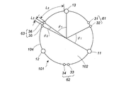
- FIG. 1 is a perspective view of a housing used in a gas generator, but used only to indicate the location of the gas outlet.
- FIG. 2 is a plan view showing the arrangement when the gas discharge port is formed in the peripheral wall portion of the housing, but is a view in which the position of the gas discharge port not visible in the plan view is visible.
- FIG. 3 is a plan view similar to FIG. 2 showing an arrangement of a gas discharge port according to still another embodiment.
- FIG. 4 is a plan view similar to FIG. 2 showing an arrangement of a gas discharge port according to still another embodiment.
- FIG. 5 is a plan view similar to FIG. 2 showing an arrangement of a gas discharge port according to still another embodiment.
- FIG. 6 is a plan view similar to FIG.
- FIG. 7 is a plan view similar to FIG. 2 showing an arrangement of a gas discharge port according to still another embodiment.
- FIG. 8 is a plan view similar to FIG. 2 showing an arrangement of a gas discharge port according to still another embodiment.
- FIG. 9 is a perspective view of a gas generator according to still another embodiment.
- FIG. 10 is a perspective view of a gas generator according to still another embodiment.
- JP2008-201243A is for prioritizing the discharge of gas in a specific direction, and there is only an example in which all the gas discharge ports are broken (paragraphs 0036 and 0037).
- the size of the gas outlet is not intended to control the burst pressure of the sealing tape.
- the gas generator has a plurality of first openings at which the burst pressure (P1) of a closing member such as a seal tape for closing the opening of the gas outlet is low, and the burst pressure than the burst pressure (P1)
- P1 burst pressure
- P2 has a high gas outlet comprising a plurality of second openings
- the first opening may be opened first and the second opening may be delayed as designed, or Alternatively, it provides a gas generator in which only the first opening is opened and the influence does not reach the second opening.
- the gas generator of the first aspect can be applied to both a single type of igniter for igniting and burning a gas generating agent and a dual type of igniter. Moreover, it is applicable also to the gas generator of the hybrid type which uses a gas generating agent and pressurization gas together. The same applies to the other embodiments described below.
- the housing of the gas generator according to the first aspect is a disk-shaped housing in which the ratio of the outer diameter D to the axial length L is L / D ⁇ 1.1.
- the gas discharge port may be formed in the peripheral wall portion, the top plate portion, or both the peripheral wall portion and the top plate portion, depending on the installation place of the gas generator in the vehicle and the like.
- the plurality of first openings and the plurality of second openings are formed in such a manner that the centers of the plurality of first openings and the plurality of second openings are formed on the same circumference.
- the gas outlet may be closed with a metallic sealing tape from the inside for moisture proofing purposes.
- the gas outlet is closed by a closing member, and the first opening with a low burst pressure (P1) of the closing member and a plurality of second openings with a higher burst pressure (P2) than the burst pressure (P1) It is a combination (P1 ⁇ P2).
- the first opening of the burst pressure (P1) and the second opening of the burst pressure (P2) are (I) A mode in which the opening diameter of the first opening is larger than the opening diameter of the second opening, and the first opening and the second opening are closed by the same seal tape, (Ii) The opening diameter of the first opening and the opening diameter of the second opening are the same, and a sealing tape (first sealing tape) closing the first opening and a sealing tape closing the second opening (second The tensile strength of the sealing tape) is such that the tensile strength of the first sealing tape ⁇ the tensile strength of the second sealing tape, (Iii) It can be set as any aspect of the aspect which combined the aspect of (i) and the aspect of (ii) above.
- the arrangement form of the plurality of first openings and the plurality of second openings is appropriately adjusted in accordance with the function required of the gas generator, but the gas generator of the present invention is an object of the present invention. In order to solve the problem, it is desirable to meet the following requirements.
- first opening and the second opening adjacent in the circumferential direction of the same circle have a first center line passing through the center of the same circle and the center of the first opening, and the center and the second of the same circle.
- the angle ( ⁇ 1) with the second center line passing through the center of the opening is set to be in the range of 15 ° to 65 °.
- the gas generator according to the first aspect ensures the function when the first opening mainly opens first and the second opening opens later or only the first opening opens when activated It is.
- the gas generating agent burns to generate combustion gas, and the air bag can be inflated.
- the first opening and the second opening are disposed close to each other, the first opening is preferentially opened, and as a result, the combustion gas flow is concentrated on the opened first opening, There may be a problem that the adjacent second openings may be opened together under the influence of the combustion gas flow.
- the problem is that igniters can occur in both single single type gas generator and igniters in two dual type gas generators, but in particular two igniters operate with time lag This is an important issue in dual type gas generators.
- the first opening and the second opening are disposed at a predetermined angle ( ⁇ 1) range, and the influence of the combustion gas flow on the first opening that is opened is Since the second opening is difficult to receive, it is possible to avoid the problem that the second opening is opened when it should not be opened as described above.
- the gas generator of the second aspect can be applied to both a single type of igniter for igniting and burning a gas generating agent and a dual type of igniter. Moreover, it is applicable also to the gas generator of the hybrid type which uses a gas generating agent and pressurization gas together.
- the housing of the gas generator according to the second aspect is a disk-shaped housing in which the ratio of the outer diameter D to the axial length L is L / D ⁇ 1.1.
- the gas discharge port may be formed in the peripheral wall portion, the top plate portion, or both the peripheral wall portion and the top plate portion depending on the installation place of the gas generator and the like.
- the plurality of first openings and the plurality of second openings are formed in such a manner that the centers of the plurality of first openings and the plurality of second openings are formed on the same circumference.
- the gas outlet may be closed with a metallic sealing tape from the inside for moisture proofing purposes.
- the gas outlet is closed by a closing member, and the first opening with a low burst pressure (P1) of the closing member and a plurality of second openings with a higher burst pressure (P2) than the burst pressure (P1) It is a combination (P1 ⁇ P2).
- the first opening of the burst pressure (P1) and the second opening of the burst pressure (P2) are the same as in the gas generator of the first aspect, in the same embodiment (i), (ii) or (iii) can do.
- the arrangement of the plurality of first openings and the plurality of second openings is selected from the arrangements of (a) to (f).
- the arrangement of the plurality of first openings and the plurality of second openings is adjusted in accordance with the requirements for the gas generator different depending on the installation location in the vehicle, the vehicle type, etc., (a) In (f), the arrangement of the plurality of first openings and the plurality of second openings is specifically made.
- first openings are arranged as one group to form three groups in total (group 1a, group 2a, group 3a), group 1a
- One second opening is disposed between the second group and the second group, between the second group and the third group, and between the third group and the first group.
- three second openings are arranged as one group so as to form three groups in total (groups 1b, 2b, 3b), group 1b
- One first opening is disposed between the second group and the second group, between the second group and the third group, and between the third group and the first group.
- two first openings are arranged as one group so as to form three groups in total (group 1a, group 2a, group 3a), two first The two openings are arranged in one group as a total of three groups (groups 1b, 2b, 3b).
- the arrangement order of the respective groups is determined according to the performance required of the gas generator, and as long as the performance satisfies the performance, it may be regular or random. For example, they are alternately arranged with groups 1a, 1b, 2a, 2b, 3a and 3b, and arranged on the same circumference such that the intervals between the groups are equal.
- one first opening or second opening is arranged between adjacent groups.
- one first opening or second opening is provided between the plurality of first openings or the plurality of second openings constituting each group.
- the department is arranged.
- the group 1a includes four first openings
- one second opening is disposed at an intermediate position of the four first openings
- the group 1b includes four second openings.
- it is a form by which one 1st opening is arrange
- the half circle is another arrangement.
- the half circle can be in the arrangement form of (a), and the remaining half circle can be in the arrangement form of (b).
- a distance between a plurality of second openings forming the second opening group is in the arrangement form of (b), (c), (d) and (e), and ⁇ 1> ⁇ 2 It is arranged to become.
- ⁇ 2 30 °
- ⁇ 1 always has an angle larger than 30 °.
- the intervals between the plurality of first openings forming the first opening group are equal intervals (L1).
- the distance (L3) between the L1 and the second opening circumferentially adjacent to the first opening has a relationship of L1 ⁇ L3.
- first openings are arranged as one group to form three groups in total (group 1a, group 2a, group 3a), group 1a
- One second opening is disposed between the second group and the second group, between the second group and the third group, and between the third group and the first group.
- the intervals between the three first openings in each of the 1a-th group, the 2a-th group, and the 3a-th group are equal (L1).
- the distance (L3) between the first opening of the group 1a circumferentially adjacent to the second opening (L3), or the second The distance (L3) between the opening and the first opening of the 2a group adjacent in the circumferential direction satisfies the relationship of L1 ⁇ L3.
- the intervals between the plurality of second openings forming the second opening group are equal intervals (L2), A distance (L3) between the L2 and the first opening circumferentially adjacent to the second opening has a relationship of L3> L2.
- three second openings are arranged as one group into three groups (groups 1b, 2b and 3b), groups 1b and 1b
- One first opening is disposed between the group 2b, between the groups 2b and 3b, and between the group 3b and the group 1b.
- the intervals between the three first openings in each of the 1b's, 2b's, and 3b's are equally spaced (L2).
- L3 the distance between the second openings of the group 1b circumferentially adjacent to the first opening, or the first opening
- the distance (L3) between the openings and the second openings of the second group 2b circumferentially adjacent to each other satisfies the relationship of L2 ⁇ L3.
- the intervals between the plurality of first openings forming the first opening group are equal intervals (L1)
- the second The intervals between the plurality of second openings forming the opening group are equal intervals (L2)
- the distance L3 between the first opening and the second opening adjacent in the circumferential direction has a relationship of L3> L1 and L3> L2.
- two first openings are arranged as one group into three groups (groups 1a, 2a and 3a), and two second openings Parts are arranged as one group into three groups (groups 1b, 2b and 3b), each of which is group 1a, group 1b, group 2a and 2a
- the groups are arranged alternately on the same circumference so as to alternate with the 2b group third group and the 3b group, and the intervals between the groups are equal.
- the distance between the first openings in the first opening group (the first group, the second group, and the third group) is L1.
- the distance between the first openings in the second opening group (the first group, the second group, the third group) is L2.
- the groups 1a and 1b are adjacent to each other in the circumferential direction, and the first opening (end first opening) at the end of the group 1a and the second opening of the group 1b, The distance between the second openings located closest to the end first opening is L3.
- L1, L2 and L3 have a relationship of L3> L1 and L3> L2. As described above, since the relationship L3> L1 and L3> L2 is satisfied, it is possible to prevent the second opening from being affected by the flow of the combustion gas discharged from the first opening opened as in the first aspect. Be done.
- the intervals between the plurality of first openings forming the first opening group are equal intervals (L1)
- the second The intervals between the plurality of second openings forming the opening group are equal intervals (L2), L1, L2, a first opening independently disposed between the first opening group and the second opening group, and a second opening group adjacent to the independently disposed first opening
- the distance (L3) between the first openings (adjacent first openings) of the first opening group adjacent to the openings has a relationship of L3> L1 and L3> L2.
- the first opening or the second opening is disposed between the first group and the third group, between the third group and the third group, and between the third group and the first group.
- the distance between the first openings in the first opening group (the first group, the second group, and the third group) is L1.
- the distance between the first openings in the second opening group (the first group, the second group, the third group) is L2.
- Between the first opening independently disposed between the groups 1a and 1b and the distance between the second openings of the group 1b adjacent to the independently disposed first opening, or between the groups 1a and 1b A distance between the second opening independently disposed between the first opening and the first opening of the first group la adjacent to the independently disposed second opening is L3.
- L1, L2 and L3 have a relationship of L3> L1 and L3> L2. As described above, since the relationship L3> L1 and L3> L2 is satisfied, it is possible to prevent the second opening from being affected by the flow of the combustion gas discharged from the first opening opened as in the first aspect. Be done.
- the gas generator according to a preferred alternative of the second aspect is characterized in that, in the configuration form (e), The intervals between the plurality of first openings forming the first opening group are equal intervals (L1), and the intervals between the L1 and the second openings circumferentially adjacent to the first opening (L1) L3) has a relationship of L3> L1, The intervals between the plurality of second openings forming the second opening group are equal intervals (L2), and the interval between the L2 and the first openings circumferentially adjacent to the second opening ( L3) has a relationship of L3> L2.
- the distance between the first openings in the first opening group (the first group, the second group, and the third group) is L1.
- the distance between the first openings in the second opening group (the first group, the second group, the third group) is L2.
- a distance between the second opening and the first opening adjacent to both sides of the second opening or four second
- a distance between the first opening and a second opening adjacent to both sides of the first opening is L3.
- L1, L2 and L3 have a relationship of L3> L1 and L3> L2. As described above, since the relationship L3> L1 and L3> L2 is satisfied, it is possible to prevent the second opening from being affected by the flow of the combustion gas discharged from the first opening opened as in the first aspect. Be done.
- one second opening is provided at an intermediate position between the two groups. It may be an arrangement form with parts.
- one of the first openings is located at an intermediate position between the two groups. It may be an arrangement having an opening.
- the plurality of first openings and the plurality of second openings are When the plurality of first openings and the plurality of second openings are formed in the peripheral wall, a plurality of rows are formed on the same circumference of each of the different positions of the height of the peripheral wall, When the plurality of first openings and the plurality of second openings are formed in the top plate, a plurality of lines are formed on the top plate so as to form a multiple circle.
- the gas discharge ports are formed in the peripheral wall portion of the housing, they are formed in a plurality of rows of different heights.
- the gas discharge ports in the first row are formed on the circumference of the same height, and circles of the same height spaced in the height direction
- the second row of gas discharge ports is formed on the circumference, and the third or more rows of gas discharge ports are formed in the same manner. It is an aspect.
- the gas discharge ports are formed in the top plate of the housing, a plurality of rows are formed so as to form a multiple circle.
- the first row gas discharge ports (combination of a plurality of first openings and a plurality of second openings) are formed on the circumference of one identical circle, and the second row The gas outlet (combination of a plurality of first openings and a plurality of second openings) is formed, and in a similar manner, gas outlets of a third row or more are formed.
- the housing of the gas generator according to the third aspect is a disk-shaped housing in which the ratio of the outer diameter D to the axial length L is L / D ⁇ 1.1.
- the gas discharge port may be formed in the peripheral wall portion, the top plate portion, or both the peripheral wall portion and the top plate portion, depending on the installation place of the gas generator and the like.
- the plurality of first openings and the plurality of second openings are formed in such a manner that the centers of the plurality of first openings and the plurality of second openings are formed on the same circumference.
- the gas outlet may be closed with a metallic sealing tape from the inside for moisture proofing purposes.
- the gas outlet is closed by a closing member, and the first opening with a low burst pressure (P1) of the closing member and a plurality of second openings with a higher burst pressure (P2) than the burst pressure (P1) It is a combination.
- the first opening of the burst pressure (P1) and the second opening of the burst pressure (P2) have the same aspect (i), (ii) or (iii) as the gas generator according to the first aspect be able to.
- the igniter is housed inside a cup member having a plurality of transfer holes in the peripheral wall portion.
- the planar shape of the cup member is circular, and the plurality of transmission holes are unevenly distributed on the semicircular side (first semicircular side) of the peripheral wall portion of the cup member. Of the total number of transfer holes, more than 2/3 of the total number are formed on the first semicircular side, and the remaining part is formed on the other semicircular side (second semicircular side) . Since all transfer holes have the same size, in operation, combustion products containing more flames are released from the side of the first semicircle with many transfer holes.
- the cup member i.e., the igniter
- the first semicircular side of the cup member is at a position far from the peripheral wall portion of the housing.
- the semicircular side is closer to the peripheral wall of the housing.
- the volume of the combustion chamber facing the first semicircular side of the cup member far from the peripheral wall of the housing is larger than the volume of the combustion chamber facing the second semicircular side closer to the housing circumferential wall, More gas generating agent will be present on the semicircular side.
- the semicircular side of the housing corresponding to the semicircular side (first semicircular side) of the peripheral wall portion of the cup member in which the plurality of transfer holes are unevenly distributed is taken as a first semicircular region, and the second semicircular side of the remaining portion
- the total opening area (A1) of the plurality of first openings and the plurality of second openings formed in the first semicircular area and the second semicircular area The ratio (A2 / A1) of the total opening area (A2) of the plurality of first openings and the plurality of second openings is in the range of 0.25 to 0.40.
- the combustion chamber volume on the first semicircle side of the cup member far from the housing that is, the volume of the first semicircle region
- the combustion chamber volume on the second semicircle side closer to the housing that is, the second semicircle (The volume of the region)
- more gas generant is present in the first semi-circular region.
- the openings of the transfer holes are provided corresponding to the burning surface area of the gas generating agent in the combustion chamber of each of the first semicircular region and the second semicircular region, the first semicircular region and the second semicircular region are provided. There is almost no difference in the flammability of the gas generant in the circular region.
- the housing of the gas generator according to the fourth aspect has a cylindrical shape in which the ratio of the outer diameter D to the axial length L is L / D> 1.1.
- the gas discharge port is formed in the peripheral wall portion, and the formation position can be adjusted in accordance with the installation place of the gas generator and the like.
- the plurality of first openings and the plurality of second openings are formed such that the centers thereof are on the same circle.
- the gas outlet may be closed with a metallic sealing tape from the inside for moisture proofing purposes.
- the gas outlet is closed by a closing member, and the first opening with a low burst pressure (P1) of the closing member and a plurality of second openings with a higher burst pressure (P2) than the burst pressure (P1) It is a combination (P1 ⁇ P2).
- the first opening of the burst pressure (P1) and the second opening of the burst pressure (P2) have the same aspect (i), (ii) or (iii) as the gas generator according to the first aspect be able to. The same applies to the other embodiments described below.
- the first opening and the second opening adjacent in the circumferential direction of the same circle have a first center line passing through the center of the same circle and the center of the first opening, the center of the same circle, and the second opening And the angle ( ⁇ 1) with the second center line passing through the center of the range of 15 ° to 65 °.
- the function is reliably ensured when the first opening mainly opens first and the second opening opens later or only the first opening opens in operation.
- the gas generating agent burns to generate combustion gas, and the air bag can be inflated.
- the igniter can be generated by both a single type gas generator and a dual type gas generator, but two igniters in particular have a time difference. This is an important issue in dual-type gas generators that operate.
- the first opening and the second opening are disposed at a predetermined angular range ( ⁇ 1), and the influence of the flow of combustion gas on the first opening that is opened is Since the second opening is difficult to receive, it is possible to avoid the problem that the second opening is opened when it should not be opened as described above.
- the arrangement of the plurality of first openings and the plurality of second openings is the arrangement of (a) to (f) in the invention of the second aspect.
- the plurality of first openings and the plurality of second openings may be formed in a plurality of rows at intervals in the axial direction of the cylindrical housing, in which case (a) to (f) It may be in a different arrangement form selected from The arrangement of (a) to (f) is the same as the arrangement of (a) to (f) of the second aspect of the invention.
- the gas generator according to the present invention is a gas comprising a plurality of first openings having a low burst pressure (P1) of the closing member and a plurality of second openings having a burst pressure (P2) higher than the burst pressure (P1).
- P1 low burst pressure
- P2 burst pressure
- the second opening is less susceptible to the influence of the flow of combustion gas to the first opening, so the second opening breaks when it should not be cleaved. Does not occur.
- the gas generator of the present invention can be used as a gas generator for an air bag apparatus mounted on a vehicle.
- the gas generator of the present invention generates gas in the housing except the arrangement form of the gas outlets. It is the same as a known gas generator containing an agent, an igniter, a filter and the like.
- the igniter may be one or more.
- FIG. 1 is a perspective view of a gas generator 100 having a housing 101.
- the housing 101 includes a top plate 102, a bottom plate 103 axially opposed to the top plate 102, and a peripheral wall portion 104 between the top plate 102 and the bottom plate 103, and has a flange portion 105 used for attachment to a module case There is.
- the housing 101 has a disk shape in which the ratio of the outer diameter D to the axial length L is L / D ⁇ 1.1.
- first gas discharge ports (first opening) 11 and 12 and the second gas discharge ports (second opening) 31 and 32 are formed only in the peripheral wall portion 104, but Alternatively, the gas discharge port may be formed only on the top plate 102, or the gas discharge port may be formed on both the top plate 102 and the peripheral wall portion 104.
- the gas discharge ports are formed in only one line in the circumferential direction, but a plurality of lines may be formed at intervals in the axial direction.
- FIG. 2 is shown so that the arrangement of the gas discharge ports formed in the peripheral wall portion 104 of the housing 1 can be easily understood.
- the burst pressure (P2) is higher than the plurality of first openings 11 to 14 with low burst pressure (P1) of the closing member closing the gas discharge port and burst pressure (P1).
- the plurality of second openings 31 to 34 are combined.
- the diameters of the first openings 11 to 14 are larger than those of the second openings 31 to 34.
- the first openings 11 to 14 and the second openings 31 to 34 are all made of the same metal sealing tape. It is closed from the inside. Therefore, the burst pressure (P1) of the first openings 11 to 14 is lower than the burst pressure (P2) of the second openings 31 to 34 (p1 ⁇ P2).
- the first openings 11 to 14 and the second openings 31 to 34 are alternately arranged on the same circumference.
- “on the same circumference” means that the centers of all of the first openings 11 to 14 and the second openings 31 to 34 are on the same circumference. Also in the other embodiments below, all the centers of the plurality of first openings and the plurality of second openings are on the same circumference (peripheral wall surface).
- the first opening 11 and the second opening 31 adjacent in the circumferential direction are the center of the same circle and the second opening 31 with the first center line 1 passing through the center of the same circle and the center of the first opening 11.
- An angle ( ⁇ 1) with the second center line 2 passing through the center of the range of 15 ° to 65 ° is set.
- the second opening 33, the second opening 33 and the first opening 14, and the first opening 14 and the second opening 3 are also arranged such that the range of the angle ( ⁇ 1) is satisfied.
- the first opening 11 14 opens first, and the second openings 31 to 34 having a high burst pressure are opened later, so that the air bag can be inflated by discharging the gas with a time lag. In some cases, only the first openings 11 to 14 may open.
- igniters can occur in both single single type gas generator and igniters in two dual type gas generators, but in particular two igniters operate with time lag This is an important issue in dual type gas generators.
- the first openings 11 to 14 and the second openings 31 to 34 are arranged at a predetermined angle (.theta.1). Since the second openings 31 to 34 are less susceptible to the influence of the flow of combustion gas to the first openings 11 to 14 that have been opened, the opening time at which the second openings 31 to 34 were designed as described above There is no problem of opening faster than before.
- FIG. 3 shows the arrangement form of (a) described above as the gas discharge port.
- the first openings 11 and 12 have a first group 51
- the first openings 13 and 14 have a second group 52
- the first openings 15 and 16 have a third group 53
- the first openings 17 and 18 have a fourth group
- the first group 51 to the fourth group 54 are arranged at equal intervals.
- the second opening 31 is disposed at an intermediate position between the first group 51 and the second group 52, and the second opening 32 is disposed at an intermediate position between the second group 52 and the third group 53.
- the second opening 33 is disposed at an intermediate position between the fourth group 54 and the second opening 34 at an intermediate position between the fourth group 54 and the first group 51.
- a second opening 31 circumferentially adjacent to the first opening 12 of the first group 51 has a center of the same circle (the same as the center of the top plate 102), a center line passing through the first opening 12, and
- the angle ( ⁇ 1) between the center lines passing through the two openings 31 is in the range of 15 ° to 65 °.
- first opening 12 and the second opening 31 Similar to the first opening 12 and the second opening 31 described above, the adjacent second opening 31 and the first opening 13, the first opening 14 and the second opening 32, and the second opening 32 and the second opening 31. 1 opening 15, first opening 16 and second opening 33, second opening 33 and first opening 17, first opening 18 and second opening 34, second opening 34 and first opening
- the angle ( ⁇ 1) between each of the parts 11 is also in the range of 15 ° to 65 °.
- the intervals between the two first openings forming the first opening groups 51 to 54 are all equal (L1).
- the distance between the two first openings is, for example, the arc of each of the first opening 11 and the first opening 12 (a part of the circumference, and the two first openings are closest to each other). Is the distance between the arcs of the part). The same applies to the other embodiments described below.
- the distance (L3) between the first opening forming the first opening group 51 to 54 and the second opening circumferentially adjacent to the first opening has a relationship of L1 ⁇ L3. There is.
- the distance between the first opening 11 and the first opening 12 of the first group 51 is L1
- the distance between the first opening 12 and the second opening 31 is L3.
- L3 / L1 is preferably in the range of 1 to 27.
- the arrangement of the gas discharge ports is preferably adjusted by adding the relationship between L1 and L3 in addition to ⁇ 1.
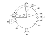
- FIG. 4 shows the arrangement form of (b) described above as the gas discharge port.
- the second openings 31 and 32 form a first group 61
- the second openings 33 and 34 form a second group 62
- the second openings 35 and 36 form a third group 63.
- the third group 63 is arranged at equal intervals.
- the first opening 11 is disposed at an intermediate position between the first group 61 and the second group 62
- the first opening 12 is disposed at an intermediate position between the second group 62 and the third group 63
- the first opening 13 is disposed at an intermediate position between the first group 61 and the first group 61.
- the first opening 11 circumferentially adjacent to the second opening 32 of the first group 61 has a center of the same circle (the same as the center of the top plate 102), a center line passing through the second opening 32, and The angle ( ⁇ 1) between the center lines passing through the opening 11 is in the range of 15 ° to 65 °.
- the angle ( ⁇ 1) between each of the second opening 35 and the second opening 36 and the first opening 13 is also in the range of 15 ° to 65 °.
- an angle ( ⁇ 2) between two center lines passing through the centers of the same circle (same as the center of the top plate 102) and the centers of the adjacent second openings is 10 ° It is arranged to be in the range of ⁇ 30 ° and to satisfy ⁇ 1> ⁇ 2.
- the angle between the line passing through the center of the same circle and the center of the second opening 31 and the center of the second opening 32 is in the range of 10 ° to 30 °.
- the intervals between the two second openings forming the second opening groups 61 to 63 are all equal (L2).
- the distance between the two second openings is, for example, a circular arc between the second opening 31 and the second opening 32 (a part of the circumference, and the two first openings are close to each other). Between arcs).
- the distance (L2) between the second openings forming the second opening group 61 to 63 and the distance (L3) between the second openings and the first openings circumferentially adjacent to each other are L2 ⁇ L3.
- the distance between the second opening 35 and the second opening 36 of the third group 63 is L2
- the distance between the first opening 36 and the first opening 13 is L3.
- L3 / L2 is preferably in the range of 1-15.
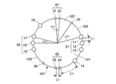
- FIG. 5 shows the arrangement form of (c) described above as the gas discharge port.
- the second openings 31, 32 form a 1b group 61 and the second openings 33, 34 form a 2b group 62
- the first openings 11, 12, 13 form a 1a group 51
- a first opening 14, 15 and 16 form the 2a group 52, and are arranged at equal intervals in the order of the 1b group 61, the 1a group 51, the 2b group 62, and the 2a group 52 on the same circumference. ing.
- the angle 16 ( ⁇ 1) between two center lines passing through the centers of the first opening and the second opening adjacent to the center of the same circle (the same as the center of the top plate 102) is 15 ° to 65 °. Range.
- an angle ( ⁇ 2) between two center lines passing through the centers of the same circle (same as the center of the top plate 102) and the adjacent first openings is 10 ° It is arranged to be in the range of ⁇ 30 ° and to satisfy ⁇ 1> ⁇ 2.
- the angle ( ⁇ 2) between the center of the circle and the line passing through the center of the first opening 15 and the center of the first opening 16 is in the range of 10 ° to 30 °.
- an angle ( ⁇ 3) between two center lines passing through the center of the same circle (same as the center of top plate 102) and the centers of the adjacent second openings is 10 ° It is arranged to be in the range of ⁇ 30 ° and to satisfy ⁇ 1> ⁇ 3.
- the angle ( ⁇ 3) between the line passing through the center of the same circle and the center of the second opening 31 and the center of the second opening 32 is in the range of 10 ° to 30 °.
- the same effect as the arrangement form shown in 2 is obtained.
- the intervals between the plurality of first openings forming the 1a group 51 and the 2a group 52 of the first opening group are equally spaced (L1), and The intervals between the plurality of second openings forming the first group b 61 and second group b 62 of the two opening groups are equal intervals (L2).
- the distance (L3) between the first opening and the second opening adjacent in the circumferential direction has a relationship of L3> L1 and L3> L2.
- L3> L1 and L3> L2 the distance between the first openings 11 to 13 of the group 1a 51 is L1
- the distance between the second openings 31 and 32 of the group 1b 61 is L2
- the distance between the second opening 32 and the first opening 11 is It becomes L3, and it has a relation of L3> L1 and L3> L2.
- L3 / L1 is preferably in the range of 1 to 27
- L3 / L2 is preferably in the range of 1 to 15.
- FIG. 6 shows the arrangement form of (d) described above.
- the 1b group 61 including the second openings 31 and 32 is disposed, and the 2b group 62 including the second openings 34 and 35 is disposed at a position opposed to the 1b group 61 in the radial direction.
- a first group 51 composed of the first openings 11 to 13 is disposed between the first group b 61 and the second b group 62, and includes first openings 15 to 17 at positions opposite to the first group 51 in the radial direction.
- the 2a group 52 is disposed.
- the second opening 33 is independently disposed between the 1b group 61 and the 1a group 51, and the first opening 14 is independently disposed between the 1a group 51 and the 2b group 62, and the 2b group 62 and the 1st
- the second opening 36 is independently disposed between the 2a group 52, and the first opening 18 is independently disposed between the 2a group 52 and the 1b group 61.
- the first opening 11 of the 1a group 51 adjacent to the second opening 33 independently disposed in the circumferential direction passes through the center of the same circle (the same as the center of the top plate 102) and the second opening 33.
- the angle ( ⁇ 1) between the center line and the center line passing through the first opening 11 is in the range of 15 ° to 65 °.
- the angle ( ⁇ 1) between each of the two openings 31 is also in the range of 15 ° to 65 °.
- an angle ( ⁇ 2) between two center lines passing through the centers of the same circle (same as the center of the top plate 102) and the adjacent first openings is 10 ° It is arranged to be in the range of ⁇ 30 ° and to satisfy ⁇ 1> ⁇ 2.
- the angle ( ⁇ 2) between the center of the same circle and the line passing through the center of the first opening 15 and the center of the first opening 16 is in the range of 10 ° to 30 °.
- an angle ( ⁇ 3) between two center lines passing through the center of the same circle (same as the center of top plate 102) and the centers of the adjacent second openings is 10 ° It is arranged to be in the range of ⁇ 30 ° and to satisfy ⁇ 1> ⁇ 3.
- the angle ( ⁇ 3) between the line passing through the center of the same circle and the center of the second opening 31 and the center of the second opening 32 is in the range of 10 ° to 30 °.
- the same effect as the arrangement form shown in 2 is obtained.
- the intervals between the plurality of first openings forming the 1a group 51 and the 2a group 52 of the first opening group are equally spaced (L1), and The intervals between the plurality of second openings forming the first group b 61 and second group b 62 of the two opening groups are equal intervals (L2).
- the distance (L3) between the first opening and the second opening adjacent in the circumferential direction has a relationship of L3> L1 and L3> L2.
- L3> L1 and L3> L2 the distance between the first openings 11 to 13 of the 1a group 51 is L1
- the distance between the second openings 34 and 35 of the 1b group 62 is L2
- the distance between the second opening 34 and the first opening 14 is It becomes L3, and it has a relation of L3> L1 and L3> L2.
- L3 / L1 is preferably in the range of 1 to 27
- L3 / L2 is preferably in the range of 1 to 15.
- a gas generator having the arrangement form of the gas discharge port shown in FIG. 7 The arrangement form of another embodiment of (d) shown in FIG. 7 is as follows.
- the first group 61 including the second openings 31 to 33 is disposed, and the first group 51 including the first openings 11 and 12 sequentially in the circumferential direction from the first group 61 as a starting point;
- a fourth group 54 including the first opening 18 and the first openings 19 and 20 is disposed.
- the first opening 11 of the 1a group 51 adjacent to the second opening 33 of the 1b group 61 in the circumferential direction is the center of the same circle (the center of the top 101) and the center passing through the second opening 33
- the angle ( ⁇ 1) between the line and the center line passing through the first opening 11 is in the range of 15 ° to 65 °.
- the angle ( ⁇ 1) between each of the two openings 31 is also in the range of 15 ° to 65 °.
- the angle ( ⁇ 2) between two center lines passing through the centers of the same circle (same as the center of the top 102) and the centers of the adjacent first openings is 10 ° It is arranged to be in the range of ⁇ 30 ° and to satisfy ⁇ 1> ⁇ 2.
- the angle ( ⁇ 2) between the center of the same circle and the line passing through the center of the first opening 11 and the center of the first opening 12 is in the range of 10 ° to 30 °.
- an angle ( ⁇ 3) between two center lines passing through the center of the same circle (same as the center of top plate 102) and the centers of the adjacent second openings is 10 ° It is arranged to be in the range of ⁇ 30 ° and to satisfy ⁇ 1> ⁇ 3.
- an angle ( ⁇ 3) between lines passing through the center and the center of the second opening 31 and the center of the second opening 32 and the center of the second opening 32 and the second opening 33 is in the range of 10 ° to 30 °.
- the same effect as the arrangement form shown in 2 is obtained.
- the intervals between the plurality of first openings forming the first group 51a to the fourth group 54a of the first opening group are equally spaced (L1)
- the intervals between the plurality of second openings forming the first group b 61 of the second opening group and the second group b 62 are equally spaced (L 2).
- the distance (L3) between the first opening and the second opening adjacent in the circumferential direction has a relationship of L3> L1 and L3> L2.
- the distance between the first openings 11 and 12 of the 1a group 51 is L1
- the distance between the second openings 31 and 32 of the 1b group 61 is L2
- the distance between the second opening 33 and the first opening 11 is It becomes L3, and it has a relation of L3> L1 and L3> L2.
- L3 / L1 is preferably in the range of 1 to 27
- L3 / L2 is preferably in the range of 1 to 15.
- FIG. 8 shows the arrangement form of (e) described above as the gas discharge port.
- the arrangement form of (e) is An embodiment in which one first opening 11 is disposed in the four second openings 31, 32, 37, 38 consisting of the 1b group 61 and the 4b group 64, and 2b group 62 and 3b In the embodiment, one first opening 15 is disposed in the four second openings 33 to 36 consisting of the group 63.
- the arrangement form of (e) is An embodiment in which there is one first opening 11 at an intermediate position between two groups of the 1b group 61 (second openings 31, 32) and the 4b group 64 (second openings 37, 38), and 2b
- the embodiment also includes an embodiment in which one first opening 15 is at an intermediate position between two groups of the group 62 (second openings 33, 34) and the third group 63b (second openings 35, 36).
- a first opening 11 is disposed independently, and a first opening 61 is used as a starting point, and a first opening 61 is a first opening 31.
- a first opening 61 is a second opening 31 and a second opening 31.
- a 4b group including the 2a group 52 and the second openings 37 and 38 is disposed.
- the second opening 31 of the 1 b group 61 adjacent to the first opening 11 in the circumferential direction has a center of the same circle (the same as the center of the top plate 102), a center line passing through the first opening 11, and
- the angle ( ⁇ 1) between the center lines passing through the two openings 31 is in the range of 15 ° to 65 °.
- first opening 11 and the second opening 31 Similar to the first opening 11 and the second opening 31 described above, the adjacent second opening 32 and the first opening 12, the first opening 14 and the second opening 33, and the second opening 34 and the second opening 31. 1 opening 15, first opening 15 and second opening 35, second opening 36 and first opening 16, first opening 18 and second opening 37, second opening 38 and first opening
- the angle ( ⁇ 1) between each of the parts 11 is also in the range of 15 ° to 65 °.
- an angle ( ⁇ 2) between two center lines passing through the centers of the same circle (same as the center of the top plate 102) and the adjacent first openings is 10 ° It is arranged to be in the range of ⁇ 30 ° and to satisfy ⁇ 1> ⁇ 2.
- the angle ( ⁇ 2) between the lines passing through the center of 14 is in the range of 10 ° to 30 °.
- an angle ( ⁇ 3) between two center lines passing through the center of the same circle (same as the center of top plate 102) and the centers of the adjacent second openings is 10 ° It is arranged to be in the range of ⁇ 30 ° and to satisfy ⁇ 1> ⁇ 3.
- an angle ( ⁇ 3) between lines passing through the center of the same circle and the center of the second opening 31 and the center of the second opening 32 and the center of the second opening 33 and the second opening The angle ( ⁇ 3) between the lines passing through the center of the portion 34 is in the range of 10 ° to 30 °.
- the same effect as the arrangement form shown in 2 is obtained.
- the intervals between the plurality of first openings forming the 1a group 51 and the 2a group 52 are equal intervals (L1), and the 1b group 61 to 4b
- the intervals between the plurality of second openings forming the group 64 are equal intervals (L2).
- the distance (L3) between the first opening and the second opening adjacent in the circumferential direction has a relationship of L3> L1 and L3> L2.
- the distance between the first openings 12 to 14 of the group 1a 51 is L1
- the distance between the second openings 31 and 32 of the group 1b 61 is L2
- the first opening 11 and the second opening 31 the second
- the distance between the opening 32 and the first opening 12 is L3, which has a relationship of L3> L1 and L3> L2.
- L3 / L1 is preferably in the range of 1 to 27
- L3 / L2 is preferably in the range of 1 to 15.
- the arrangement form of the gas generator (f) having the arrangement form partially including (a) to (e) mentioned above is a part of the arrangement form of (a) to (e) described above It is an arrangement form included in.
- one half of the circumferential direction may be the arrangement form of (a), and the other half of the circumferential direction may be the arrangement form of (b).
- the gas generator having the arrangement form of each gas discharge port described above differs in height direction (axial direction) when the gas discharge port is disposed in the peripheral wall portion 104 as shown in FIG. 1
- a gas outlet may be arranged at the position.
- a plurality of rows may be disposed so as to form a multiple circle.
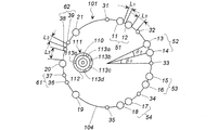
- FIG. 9 Gas generator having arrangement form of gas discharge port shown in FIG. 9
- the housing 101 of the gas generator shown in FIG. 9 has the same outer shape as that shown in FIG. Is fixed to the bottom plate 103 and accommodated in the cup member 111.
- the cup member 111 has a bottom surface portion, a peripheral wall portion 112, and an opening portion.
- the opening portion side is in contact with the bottom plate 103, and the bottom surface portion is disposed close to or in contact with the top plate 102. There is.
- a transfer charge not shown is accommodated in the space except the igniter 110 in the cup member 111.
- the transfer agent is the same as that used in known gas generators, and in addition, a gas generator that functions as a transfer agent can also be used.
- the cup member 111 has a circular planar shape, and has a plurality of transmission holes 113a to 113e in the peripheral wall portion 112.
- the transmission holes 113a to 113e of the cup member 111 are formed on the semicircular side (first semicircular side) of the peripheral wall portion of the cup member 111, and the remaining transmission holes 113e are It is formed on the remaining half circle side (second half circle side).
- the cup member 111 is at a position deviated from the central portion of the housing 101, and the first semicircular side (the transfer holes 113a to 113d side) is at a position far from the peripheral wall portion 104 of the housing 101.
- the transfer hole 113 e side is disposed so as to be close to the peripheral wall portion 104 of the housing 101.
- the arrangement of the gas generator shown in FIG. 9 corresponds to the arrangement of (e).
- the second opening 31 is disposed independently, and the first opening 51 is a starting point, the 1a group 51 including the first opening 11 and the second opening 32 independently disposed, and the first opening 13 ,
- the second opening 33 consisting of the second opening 33 and the third opening 53 consisting of the first openings 15 and 16, the second opening 34 and the first openings 17 and 18, respectively.
- the group to 4a group 54 and the independently arranged second opening 35 are arranged on a half circle.
- the second opening 35 arranged alone the first opening 19 arranged alone, the first group 61b consisting of the second openings 36 and 37, the first opening 20 arranged separately, the second The second group b 62 including the openings 38 and 39, the independently disposed first opening 21, and the independently disposed second opening 31 are disposed on the remaining half circumference.
- the 2nd opening 31 and the 2nd opening 35 are located in the middle of two half circumferences.
- the second opening 31 adjacent to the first opening 11 in the circumferential direction has the center of the same circle (the same as the center of the top plate 102), the center line passing through the first opening 11, and the second opening 31
- the angle ( ⁇ 1) between the passing center lines is in the range of 15 ° to 65 °.
- the adjacent second opening 32 and the first opening 12, 13, the second opening 33 and the first opening 14, 15, the second opening The portion 34 and the first openings 16, 17, the first opening 18 and the second opening 35, the first opening 19 and the second opening 36, the first opening 20 and the second openings 37, 38, the first The angle ( ⁇ 1) between each of the first opening 21 and the second opening 39 is also in the range of 15 ° to 65 °.
- the angle ( ⁇ 2) between two center lines passing through the centers of the same circle (same as the center of the top 102) and the centers of the adjacent first openings is 10 ° It is arranged to be in the range of ⁇ 30 ° and to satisfy ⁇ 1> ⁇ 2.
- the angle ( ⁇ 2) between the center of the same circle and the line passing through the center of the first opening 11 and the center of the first opening 12 is in the range of 10 ° to 30 °.
- an angle ( ⁇ 3) between two center lines passing through the centers of the same circle (same as the center of top plate 102) and the centers of the adjacent second openings is 10 ° It is arranged to be in the range of ⁇ 30 ° and to satisfy ⁇ 1> ⁇ 3.
- the angle ( ⁇ 3) (not shown) between the center and the line passing through the center of the second opening 36 and the center of the second opening 37 is in the range of 10 ° -30 °.
- the same effect as the arrangement form shown in 2 is obtained.
- the intervals between the plurality of first openings forming the first group 51 to the fourth group 54 are equal intervals (L1), and the first group 61b to the second b are arranged.
- the intervals between the plurality of second openings forming the group 62 are equal intervals (L2).
- the distance (L3) between the first opening and the second opening adjacent in the circumferential direction has a relationship of L3> L1 and L3> L2.
- the distance between the first openings 11 and 12 of the group 1a 51 is L1
- the distance between the first opening 12 and the second opening 32 is L3, and the distance between the first opening 11 and the second opening 31 is L3.
- the distance between the second openings 36 and 37 of the 1b group 61 is L2
- the distance between the first opening 19 and the second opening 36 is L3
- the distance between the first opening 19 and the second opening 35 is L3. It has a relationship of L3> L2.
- L3 / L1 is preferably in the range of 1 to 27, and L3 / L2 is preferably in the range of 1 to 15.
- the semicircular side of the housing 101 corresponding to the first semicircular side in which the transfer holes 113a to 113d are formed is a first semicircular area (from the second opening 31 through the first group 51).
- the second opening 35), and the semicircular side of the housing 101 corresponding to the second semicircular side in which the transfer hole 113e is formed is a second semicircular area (from the second opening 35 to the first opening).
- the ratio (A2 / A1) of the total opening area (A2) of the plurality of first openings and the plurality of second openings formed in the circular region is in the range of 0.25 to 0.40.
- the amount of released combustion products emitted from the transfer hole 113e is small, but the distance to the peripheral wall portion 104 of the housing is short, and the amount of the gas generating agent is small.
- the combustion proceeds at the same timing as the gas generator in the first semicircular region.
- the combustion gas is discharged from the first openings 11 to 21 opened earlier, and then discharged from the second openings 31 to 39 opened later.
- the first openings 11 to 21 may be discharged.
- Gas generator shown in FIG. 10 The gas generator 200 shown in FIG. 10 has a circular cross-sectional shape in the width direction, and the ratio of the outer diameter D to the axial length L is L / D> 1.1. It has a cylindrical housing 201.
- the igniter 205 is fixed to the first end 202, the second end 203 is closed, and a gas discharge port is formed in the peripheral wall 204.
- the gas generating agent is contained in the internal space (combustion chamber) of the cylindrical housing 201.
- a gas discharge port consisting of a combination of the first opening and the second opening in any of the above-mentioned arrangements (a) to (f).
- FIG. 10 the arrangement form (FIG. 3) of (a) is shown.
Landscapes
- Physics & Mathematics (AREA)
- Fluid Mechanics (AREA)
- Engineering & Computer Science (AREA)
- Mechanical Engineering (AREA)
- Chemical & Material Sciences (AREA)
- Organic Chemistry (AREA)
- Chemical Kinetics & Catalysis (AREA)
- Air Bags (AREA)
- Feeding, Discharge, Calcimining, Fusing, And Gas-Generation Devices (AREA)
Abstract
本発明は、ガス排出口を有するハウジング内にガス発生剤と点火器が収容されたガス発生器であり、 前記ハウジングが、平面形状が円形で、天板、前記天板と軸方向に対向する底板、前記天板と前記底板の間の周壁部を有し、外径Dと軸方向の長さLの比がL/D≦1.1であり、 前記ガス排出口は、閉塞部材で閉塞されており、前記閉塞部材の破裂圧(P1)が低い複数の第1開口部と、前記破裂圧(P1)よりも破裂圧(P2)が高い複数の第2開口部が組み合わされたものであり、 前記複数の第1開口部と前記複数の第2開口部が、前記周壁部と前記天板の少なくとも一方に間隔をおいて同一円の円周上に形成され、 円周方向に隣接する前記第1開口部と前記第2開口部が、前記同一円の中心と前記第1開口部の中心を通る第1中心線と、前記同一円の中心と前記第2開口部の中心を通る第2中心線とのなす角度(θ1)が15°~65°の範囲になるように配置されている、ガス発生器である。
Description
本発明は、車両に搭載するエアバッグ装置用のガス発生器として使用できるガス発生器に関する。
背景技術
エアバッグ装置で使用するガス発生器は、通常、ハウジングの周方向に均等間隔で配置された複数のガス排出口を有しており、ガス発生器が作動したときは、前記複数のガス排出口から放射状にガスが排出され、エアバッグを膨張させるようになっている。しかし、車両内におけるエアバッグ装置の取付位置、周囲の温度環境の変化などを考慮して、ガス発生器におけるガス排出口の位置、大きさなどを調整した発明が知られている。
エアバッグ装置で使用するガス発生器は、通常、ハウジングの周方向に均等間隔で配置された複数のガス排出口を有しており、ガス発生器が作動したときは、前記複数のガス排出口から放射状にガスが排出され、エアバッグを膨張させるようになっている。しかし、車両内におけるエアバッグ装置の取付位置、周囲の温度環境の変化などを考慮して、ガス発生器におけるガス排出口の位置、大きさなどを調整した発明が知られている。
JP2008-201243Aの発明では、ガス発生器の周壁部に開口面積が同じ大径ガス排出口15a、15bを6個形成し、それに直交する部分に小径ガス排出口16a、16bが1つ形成され、それらが同じ厚みのシールテープで閉塞されたものが開示されている。作動時には、大径ガス排出口15a、15bからより多くのガスを排出し、エアバッグの展開を特定の方向に優先させて展開するものである。
JPH06-183310Aの発明では、ハウジングの周壁部において、3種種類の径のオリフィスが形成されているガス発生器が開示されている。第1のオリフィス26は第2のオリフィス28よりも大きな面積を有し、両オリフィス26と28はハウジングにおいて相互に偏在するように形成されている。また第3のオリフィス34はハウジングの端部に形成され、その開口面積は、第1のオリフィス26と第2のオリフィス28の中間である。また第1、第2 のオリフィスを覆う箔32よりも第3のオリフィスを覆う箔36は厚くなっている。
これらのオリフィスは、作動時の環境温度の違いによって発生するハウジング内圧やそれによって発生する出力の相違を調整するものである。
発明の開示
本発明の第1態様(以下「第1態様」という)は、ガス排出口を有するハウジング内にガス発生剤と点火器が収容されたガス発生器であって、
前記ハウジングが、平面形状が円形で、天板、前記天板と軸方向に対向する底板、および前記天板と前記底板の間の周壁部を有しており、外径Dと軸方向の長さLの比がL/D≦1.1であるものであり、
前記ガス排出口が閉塞部材で閉塞され、前記ガス排出口は、前記閉塞部材の破裂圧(P1)が低い複数の第1開口部と、前記破裂圧(P1)よりも破裂圧(P2)が高い複数の第2開口部が組み合わされたものであり、
前記複数の第1開口部と前記複数の第2開口部が、前記周壁部と前記天板の少なくとも一方に間隔をおいて同一円の円周上に形成され、
円周方向に隣接する前記第1開口部と前記第2開口部が、前記同一円の中心と前記第1開口部の中心を通る第1中心線と、前記同一円の中心と前記第2開口部の中心を通る第2中心線とのなす角度(θ1)が15°~65°の範囲になるように配置されているものである、ガス発生器を提供する。
本発明の第1態様(以下「第1態様」という)は、ガス排出口を有するハウジング内にガス発生剤と点火器が収容されたガス発生器であって、
前記ハウジングが、平面形状が円形で、天板、前記天板と軸方向に対向する底板、および前記天板と前記底板の間の周壁部を有しており、外径Dと軸方向の長さLの比がL/D≦1.1であるものであり、
前記ガス排出口が閉塞部材で閉塞され、前記ガス排出口は、前記閉塞部材の破裂圧(P1)が低い複数の第1開口部と、前記破裂圧(P1)よりも破裂圧(P2)が高い複数の第2開口部が組み合わされたものであり、
前記複数の第1開口部と前記複数の第2開口部が、前記周壁部と前記天板の少なくとも一方に間隔をおいて同一円の円周上に形成され、
円周方向に隣接する前記第1開口部と前記第2開口部が、前記同一円の中心と前記第1開口部の中心を通る第1中心線と、前記同一円の中心と前記第2開口部の中心を通る第2中心線とのなす角度(θ1)が15°~65°の範囲になるように配置されているものである、ガス発生器を提供する。
本発明の第2態様(以下「第2態様」という)は、ガス排出口を有するハウジング内にガス発生剤と点火器が収容されたガス発生器であって、
前記ハウジングが、平面形状が円形で、天板、前記天板と軸方向に対向する底板、および前記天板と前記底板の間の周壁部を有しており、外径Dと軸方向の長さLの比がL/D≦1.1であるものであり、
前記ガス排出口が閉塞部材で閉塞され、前記ガス排出口は、前記閉塞部材の破裂圧(P1)が低い複数の第1開口部と、前記破裂圧(P1)よりも破裂圧(P2)が高い複数の第2開口部が組み合わされたものであり、
前記複数の第1開口部と前記複数の第2開口部が、前記周壁部と前記天板の少なくとも一方に間隔をおいて同一円の円周上に形成され、
前記複数の第1開口部と前記複数の第2開口部の配置形態が、
(a)前記複数の第1開口部が、互いに間隔をおいて一群となるように配置された第1開口部群を複数有しており、前記複数の第2開口部のうちの1つが前記第1開口部群の間に配置されている配置形態、
(b)前記複数の第2開口部が、互いに間隔をおいて一群となるように配置された第2開口部群を複数有しており、前記複数の第1開口部のうちの1つが前記第2開口部群の間に配置されている配置形態、
(c)前記複数の第1開口部が、互いに間隔をおいて一群となるように配置された第1開口部群を複数有しており、前記複数の第2開口部が、互いに間隔をおいて一群となるように配置された第2開口部群を複数有しており、前記第1開口部群と前記第2開口部群が周方向に間隔をおいて配置されている配置形態、
(d)前記(c)の配置形態において、前記第1開口部群と前記第2開口部群の間、前記第1開口部群同士の間、または前記第2開口部群同士の間に第1開口部または第2開口部が単独配置されている配置形態、
(e)前記(c)の配置形態において、前記第1開口部群の中に第2開口部が単独配置されているか、または前記第2開口部群の中に第1開口部が単独配置されている配置を含んでいる配置形態、
(f)前記(a)~(e)から選ばれる1または2以上の配置形態の一部を含んでいる配置形態から選ばれるいずれかの配置形態であり、
円周方向に隣接する前記第1開口部と前記第2開口部が、前記同一円の中心と前記第1開口部の中心を通る第1中心線と、前記同一円の中心と前記第2開口部の中心を通る第2中心線とのなす角度(θ1)が15°~65°の範囲になるように配置されているものである、ガス発生器を提供する。
前記ハウジングが、平面形状が円形で、天板、前記天板と軸方向に対向する底板、および前記天板と前記底板の間の周壁部を有しており、外径Dと軸方向の長さLの比がL/D≦1.1であるものであり、
前記ガス排出口が閉塞部材で閉塞され、前記ガス排出口は、前記閉塞部材の破裂圧(P1)が低い複数の第1開口部と、前記破裂圧(P1)よりも破裂圧(P2)が高い複数の第2開口部が組み合わされたものであり、
前記複数の第1開口部と前記複数の第2開口部が、前記周壁部と前記天板の少なくとも一方に間隔をおいて同一円の円周上に形成され、
前記複数の第1開口部と前記複数の第2開口部の配置形態が、
(a)前記複数の第1開口部が、互いに間隔をおいて一群となるように配置された第1開口部群を複数有しており、前記複数の第2開口部のうちの1つが前記第1開口部群の間に配置されている配置形態、
(b)前記複数の第2開口部が、互いに間隔をおいて一群となるように配置された第2開口部群を複数有しており、前記複数の第1開口部のうちの1つが前記第2開口部群の間に配置されている配置形態、
(c)前記複数の第1開口部が、互いに間隔をおいて一群となるように配置された第1開口部群を複数有しており、前記複数の第2開口部が、互いに間隔をおいて一群となるように配置された第2開口部群を複数有しており、前記第1開口部群と前記第2開口部群が周方向に間隔をおいて配置されている配置形態、
(d)前記(c)の配置形態において、前記第1開口部群と前記第2開口部群の間、前記第1開口部群同士の間、または前記第2開口部群同士の間に第1開口部または第2開口部が単独配置されている配置形態、
(e)前記(c)の配置形態において、前記第1開口部群の中に第2開口部が単独配置されているか、または前記第2開口部群の中に第1開口部が単独配置されている配置を含んでいる配置形態、
(f)前記(a)~(e)から選ばれる1または2以上の配置形態の一部を含んでいる配置形態から選ばれるいずれかの配置形態であり、
円周方向に隣接する前記第1開口部と前記第2開口部が、前記同一円の中心と前記第1開口部の中心を通る第1中心線と、前記同一円の中心と前記第2開口部の中心を通る第2中心線とのなす角度(θ1)が15°~65°の範囲になるように配置されているものである、ガス発生器を提供する。
本発明の第3態様(以下「第3態様」という)は、ガス排出口を有するハウジング内にガス発生剤と点火器が収容されたガス発生器であって、
前記ハウジングが、平面形状が円形で、天板、前記天板と軸方向に対向する底板、および前記天板と前記底板の間の周壁部を有しており、外径Dと軸方向の長さLの比がL/D≦1.1であるものであり、
前記点火器が、前記底板に固定されかつ開口部側が前記底板に当接された、周壁部に複数の伝火孔を有するカップ部材内部に収容されており、
前記複数の伝火孔が、前記カップ部材の周壁部の半円側(第1半円側)に偏在しており、前記カップ部材が、平面形状が円形で、前記ハウジングの中心部から偏った位置であり、前記カップ部材の第1半円側が前記ハウジングの周壁部から遠い位置になるように、前記ハウジング内部に形成された燃焼室に配置されているものであり、
前記ガス排出口が閉塞部材で閉塞され、前記ガス排出口は、前記閉塞部材の破裂圧(P1)が低い複数の第1開口部と、前記破裂圧(P1)よりも破裂圧(P2)が高い複数の第2開口部が組み合わされたものであり、
前記複数の第1開口部と前記複数の第2開口部が、前記周壁部と前記天板の少なくとも一方に間隔をおいて同一円周上に形成され、
前記複数の第1開口部と前記複数の第2開口部の配置形態が第2態様記載の(a)~(f)のいずれかの配置形態であり、
前記複数の伝火孔が偏在した前記カップ部材の周壁部の第1半円側に対応する前記ハウジングの半円側を第1半円領域とし、残部の半円側を第2半円領域としたとき、前記第1半円領域に形成されている複数の第1開口部と複数の第2開口部の合計開口面積(A1)と前記第2半円領域に形成されている複数の第1開口部と複数の第2開口部の合計開口面積(A2)の比(A2/A1)が0.25~0.40の範囲である、ガス発生器を提供する。
前記ハウジングが、平面形状が円形で、天板、前記天板と軸方向に対向する底板、および前記天板と前記底板の間の周壁部を有しており、外径Dと軸方向の長さLの比がL/D≦1.1であるものであり、
前記点火器が、前記底板に固定されかつ開口部側が前記底板に当接された、周壁部に複数の伝火孔を有するカップ部材内部に収容されており、
前記複数の伝火孔が、前記カップ部材の周壁部の半円側(第1半円側)に偏在しており、前記カップ部材が、平面形状が円形で、前記ハウジングの中心部から偏った位置であり、前記カップ部材の第1半円側が前記ハウジングの周壁部から遠い位置になるように、前記ハウジング内部に形成された燃焼室に配置されているものであり、
前記ガス排出口が閉塞部材で閉塞され、前記ガス排出口は、前記閉塞部材の破裂圧(P1)が低い複数の第1開口部と、前記破裂圧(P1)よりも破裂圧(P2)が高い複数の第2開口部が組み合わされたものであり、
前記複数の第1開口部と前記複数の第2開口部が、前記周壁部と前記天板の少なくとも一方に間隔をおいて同一円周上に形成され、
前記複数の第1開口部と前記複数の第2開口部の配置形態が第2態様記載の(a)~(f)のいずれかの配置形態であり、
前記複数の伝火孔が偏在した前記カップ部材の周壁部の第1半円側に対応する前記ハウジングの半円側を第1半円領域とし、残部の半円側を第2半円領域としたとき、前記第1半円領域に形成されている複数の第1開口部と複数の第2開口部の合計開口面積(A1)と前記第2半円領域に形成されている複数の第1開口部と複数の第2開口部の合計開口面積(A2)の比(A2/A1)が0.25~0.40の範囲である、ガス発生器を提供する。
本発明の第4態様(以下「第4態様」という)は、ガス排出口を有する筒状ハウジング内にガス発生剤と点火器が収容されたガス発生器であって、
前記筒状ハウジングが、幅方向の断面形状が円形で、外径Dと軸方向の長さLの比がL/D>1.1であるものであり、
前記点火器が、前記筒状ハウジングのいずれか一方の端部に取り付けられているものであり、
前記ガス排出口が閉塞部材で閉塞され、前記ガス排出口は、前記閉塞部材の破裂圧(P1)が低い複数の第1開口部と、前記破裂圧(P1)よりも破裂圧(P2)が高い複数の第2開口部が組み合わされたものであり、
前記複数の第1開口部と前記複数の第2開口部が、前記筒状ハウジングの周壁部において同一円の円周上に形成され、
円周方向に隣接する前記第1開口部と前記第2開口部が、前記同一円の中心と前記第1開口部の中心を通る第1中心線と、前記同一円の中心と前記第2開口部の中心を通る第2中心線とのなす角度(θ1)が15°~65°の範囲になるように配置されているものである、ガス発生器を提供する。
前記筒状ハウジングが、幅方向の断面形状が円形で、外径Dと軸方向の長さLの比がL/D>1.1であるものであり、
前記点火器が、前記筒状ハウジングのいずれか一方の端部に取り付けられているものであり、
前記ガス排出口が閉塞部材で閉塞され、前記ガス排出口は、前記閉塞部材の破裂圧(P1)が低い複数の第1開口部と、前記破裂圧(P1)よりも破裂圧(P2)が高い複数の第2開口部が組み合わされたものであり、
前記複数の第1開口部と前記複数の第2開口部が、前記筒状ハウジングの周壁部において同一円の円周上に形成され、
円周方向に隣接する前記第1開口部と前記第2開口部が、前記同一円の中心と前記第1開口部の中心を通る第1中心線と、前記同一円の中心と前記第2開口部の中心を通る第2中心線とのなす角度(θ1)が15°~65°の範囲になるように配置されているものである、ガス発生器を提供する。
本発明の第5態様(以下「第5態様」という)は、ガス排出口を有する筒状ハウジング内にガス発生剤と点火器が収容されたガス発生器であって、
前記筒状ハウジングが、幅方向の断面形状が円形で、外径Dと軸方向の長さLの比がL/D>1.1であるものであり、
前記点火器が、前記筒状ハウジングのいずれか一方の端部に取り付けられているものであり、
前記ガス排出口が閉塞部材で閉塞され、前記ガス排出口は、前記閉塞部材の破裂圧(P1)が低い複数の第1開口部と、前記破裂圧(P1)よりも破裂圧(P2)が高い複数の第2開口部が組み合わされたものであり、
前記複数の第1開口部と前記複数の第2開口部が、前記筒状ハウジングの周壁部において同一円の円周上に形成され、
前記複数の第1開口部と前記複数の第2開口部の配置形態が、
(a)前記複数の第1開口部が、互いに間隔をおいて一群となるように配置された第1開口部群を複数有しており、前記複数の第2開口部のうちの1つが前記第1開口部群の間に配置されている配置形態、
(b)前記複数の第2開口部が、互いに間隔をおいて一群となるように配置された第2開口部群を複数有しており、前記複数の第1開口部のうちの1つが前記第2開口部群の間に配置されている配置形態、
(c)前記(a)の配置形態と前記(b)の配置形態が組み合わされた配置形態、
(d)前記(c)の配置形態において、前記第1開口部群と前記第2開口部群の間、前記第1開口部群同士の間、または前記第2開口部群同士の間に第1開口部または第2開口部が単独配置されている配置形態、
(e)前記(c)の配置形態において、前記第1開口部群の中に第2開口部が単独配置されているか、または前記第2開口部群の中に第1開口部が単独配置されている配置形、
(f)前記(a)~(e)から選ばれる1または2以上の配置形態の一部を含んでいる配置形態であり、
前記(a)~(f)から選ばれる1または2以上の配置形態が軸方向に複数列形成されているものである、ガス発生器を提供する。
前記筒状ハウジングが、幅方向の断面形状が円形で、外径Dと軸方向の長さLの比がL/D>1.1であるものであり、
前記点火器が、前記筒状ハウジングのいずれか一方の端部に取り付けられているものであり、
前記ガス排出口が閉塞部材で閉塞され、前記ガス排出口は、前記閉塞部材の破裂圧(P1)が低い複数の第1開口部と、前記破裂圧(P1)よりも破裂圧(P2)が高い複数の第2開口部が組み合わされたものであり、
前記複数の第1開口部と前記複数の第2開口部が、前記筒状ハウジングの周壁部において同一円の円周上に形成され、
前記複数の第1開口部と前記複数の第2開口部の配置形態が、
(a)前記複数の第1開口部が、互いに間隔をおいて一群となるように配置された第1開口部群を複数有しており、前記複数の第2開口部のうちの1つが前記第1開口部群の間に配置されている配置形態、
(b)前記複数の第2開口部が、互いに間隔をおいて一群となるように配置された第2開口部群を複数有しており、前記複数の第1開口部のうちの1つが前記第2開口部群の間に配置されている配置形態、
(c)前記(a)の配置形態と前記(b)の配置形態が組み合わされた配置形態、
(d)前記(c)の配置形態において、前記第1開口部群と前記第2開口部群の間、前記第1開口部群同士の間、または前記第2開口部群同士の間に第1開口部または第2開口部が単独配置されている配置形態、
(e)前記(c)の配置形態において、前記第1開口部群の中に第2開口部が単独配置されているか、または前記第2開口部群の中に第1開口部が単独配置されている配置形、
(f)前記(a)~(e)から選ばれる1または2以上の配置形態の一部を含んでいる配置形態であり、
前記(a)~(f)から選ばれる1または2以上の配置形態が軸方向に複数列形成されているものである、ガス発生器を提供する。
本発明は、以下の詳細な説明と添付された図面により、さらに完全に理解されるものであるが、これらはただ説明のため付されるものであり、本発明を制限するものではない。
発明の詳細な説明
JP2008-201243Aの発明は、ガスの排出を特定の方向に優先させるためのものであり、全てのガス排出口が開裂した場合の例しかなく(段落番号0036、0037)、異なる大きさのガス排出口によりシールテープの破裂圧のコントロールを意図したものではない。
JP2008-201243Aの発明は、ガスの排出を特定の方向に優先させるためのものであり、全てのガス排出口が開裂した場合の例しかなく(段落番号0036、0037)、異なる大きさのガス排出口によりシールテープの破裂圧のコントロールを意図したものではない。
本発明は、ガス発生器が、ガス排出口の開口部を閉塞するシールテープ等の閉塞部材の破裂圧(P1)が低い複数の第1開口部と、前記破裂圧(P1)よりも破裂圧(P2)が高い複数の第2開口部からなるガス排出口を有しているとき、設計どおりに前記第1開口部が先に開口され、前記第2開口部が遅れて開口されるか、または第1開口部のみが開口され、その影響が第2開口部に及ばないガス発生器を提供する。
第1態様のガス発生器は、ガス発生剤を着火燃焼させる点火器が一つのシングルタイプのもの、前記点火器が二つのデュアルタイプのものの両方に適用することができる。また、ガス発生剤と加圧ガスを併用するハイブリッドタイプのガス発生器にも適用することができる。以下の他の態様においても同様である。
第1態様のガス発生器のハウジングは、外径Dと軸方向の長さLの比がL/D≦1.1であるディスク形状のものである。
ガス排出口は、ガス発生器の車両における設置場所などに応じて、周壁部、天板部、または周壁部と天板部の両方に形成されていてもよい。
複数の第1開口部と複数の第2開口部は、複数の第1開口部と複数の第2開口部の中心が同一円周上になるように形成されている形態のほか、複数の第1開口部と複数の第2開口部の中心が同一円周上にあるものとないものが混在している形態(複数の第1開口部の中心は第1同一円周上にあり、複数の第2開口部の中心は第2同一円周上にあるが、第1同一円周と第2同一円周が同一ではなく異なっている形態を含む)、複数の第1開口部と複数の第2開口部の中心が同一円周上にはないが、少なくともそれらの開口部の一部が同一円周上にある形態を含んでいる。
ガス排出口は、防湿目的で内側から金属製のシールテープで閉塞されていてもよい。
ガス排出口は閉塞部材で閉塞され、その閉塞部材の破裂圧(P1)が低い複数の第1開口部と、破裂圧(P1)よりも破裂圧(P2)が高い複数の第2開口部が組み合わされたものである(P1<P2)。
破裂圧(P1)の第1開口部と破裂圧(P2)の第2開口部は、
(i)第1開口部の開口径が第2開口部の開口径よりも大きく、第1開口部と第2開口部が同じシールテープで閉塞されている態様、
(ii)第1開口部の開口径と第2開口部の開口径が同じで、第1開口部を閉塞するシールテープ(第1シールテープ)と第2開口部を閉塞するシールテープ(第2シールテープ)の引っ張り強度が、第1シールテープの引っ張り強度<第2シールテープの引っ張り強度である態様、
(iii)上記)(i)と(ii)の態様を組み合わせた態様、のいずれかの態様にすることができる。
(i)第1開口部の開口径が第2開口部の開口径よりも大きく、第1開口部と第2開口部が同じシールテープで閉塞されている態様、
(ii)第1開口部の開口径と第2開口部の開口径が同じで、第1開口部を閉塞するシールテープ(第1シールテープ)と第2開口部を閉塞するシールテープ(第2シールテープ)の引っ張り強度が、第1シールテープの引っ張り強度<第2シールテープの引っ張り強度である態様、
(iii)上記)(i)と(ii)の態様を組み合わせた態様、のいずれかの態様にすることができる。
複数の第1開口部と複数の第2開口部の配置形態は、ガス発生器に要求される機能に応じて適宜調整されるものであるが、本発明のガス発生器では、本発明の課題を解決するため、下記の要件を満たすことが望ましい。
即ち、同一円の円周方向に隣接する第1開口部と第2開口部は、前記同一円の中心と第1開口部の中心を通る第1中心線と、前記同一円の中心と第2開口部の中心を通る第2中心線とのなす角度(θ1)が15°~65°の範囲になるように配置されているものである。
第1態様のガス発生器は、作動時に主として第1開口部が先に開口し、第2開口部が遅れて開口する場合か、第1開口部のみが開口する場合の機能を確実にするものである。そのガス発生器を使用したエアバッグ装置が作動すると、ガス発生剤が燃焼して燃焼ガスが発生し、エアバッグを膨張させることができる。
このとき、第1開口部と第2開口部が近接して配置されていると、優先的に第1開口部が開口するので、前記開口した第1開口部に燃焼ガス流が集中する結果、近接する第2開口部が前記燃焼ガス流の影響を受けて、一緒に開口してしまうという問題が生じるおそれがある。前記問題は、点火器が一つのシングルタイプのガス発生器と点火器が二つのデュアルタイプのガス発生器の両方で発生する可能性があるが、特に二つの点火器が時間差をおいて作動するデュアルタイプのガス発生器においては重要な問題となる。
しかし、第1態様のガス発生器では、第1開口部と第2開口部が所定の角度(θ1)範囲をおいて配置されており、開口した第1開口部への燃焼ガス流の影響を第2開口部が受けにくくなっているため、上記したように第2開口部が、開口すべきでないときに開口してしまうという問題を回避することができる。
第2態様のガス発生器は、ガス発生剤を着火燃焼させる点火器が一つのシングルタイプのもの、前記点火器が二つのデュアルタイプのものの両方に適用することができる。また、ガス発生剤と加圧ガスを併用するハイブリッドタイプのガス発生器にも適用することができる。
第2態様のガス発生器のハウジングは、外径Dと軸方向の長さLの比がL/D≦1.1であるディスク形状のものである。
ガス排出口は、ガス発生器の設置場所などに応じて、周壁部、天板部、または周壁部と天板部の両方に形成されていてもよい。
複数の第1開口部と複数の第2開口部は、複数の第1開口部と複数の第2開口部の中心が同一円周上になるように形成されている形態のほか、複数の第1開口部と複数の第2開口部の中心が同一円周上にあるものとないものが混在している形態(複数の第1開口部の中心は第1同一円周上にあり、複数の第2開口部の中心は第2同一円周上にあるが、第1同一円周と第2同一円周が同一ではなく異なっている形態を含む)、複数の第1開口部と複数の第2開口部の中心が同一円周上にはないが、少なくともそれらの開口部の一部が同一円周上にある形態を含んでいる。
ガス排出口は、防湿目的で内側から金属製のシールテープで閉塞されていてもよい。
ガス排出口は閉塞部材で閉塞され、その閉塞部材の破裂圧(P1)が低い複数の第1開口部と、破裂圧(P1)よりも破裂圧(P2)が高い複数の第2開口部が組み合わされたものである(P1<P2)。
破裂圧(P1)の第1開口部と破裂圧(P2)の第2開口部は、第1態様のガス発生器と同じ(i)、(ii)または(iii)のいずれかの実施形態にすることができる。
複数の第1開口部と複数の第2開口部の配置形態は、(a)~(f)の配置形態から選ばれるものである。車両内の設置場所、車種などに異なるガス発生器への要求事項に対応して、複数の第1開口部と複数の第2開口部の配置形態は調整されるものであり、(a)~(f)は、複数の第1開口部と複数の第2開口部の配置状態が具体的にされたものである。
(a)の配置形態は、例えば、3つの第1開口部が一つの群として、合計で3つの群となるように配置され(第1a群、第2a群、第3a群)、第1a群と第2a群の間、第2a群と第3a群の間、第3a群と第1a群の間にそれぞれ一つの第2開口部が配置されているものである。
(b)の配置形態は、例えば、3つの第2開口部が一つの群として、合計で3つの群となるように配置され(第1b群、第2b群、第3b群)、第1b群と第2b群の間、第2b群と第3b群の間、第3b群と第1b群の間にそれぞれ一つの第1開口部が配置されているものである。
(c)の配置形態では、例えば、2つの第1開口部が一つの群として、合計で3つの群となるように配置され(第1a群、第2a群、第3a群)、2つの第2開口部が一つの群として、合計で3つの群となるように配置され(第1b群、第2b群、第3b群)ている。それらの各群の配置順序はガス発生器に求められる性能に応じて決定されるものであり、前記性能を満たす範囲であれば、規則性があってもよいし、ランダムであってもよい。例えば、第1a群、第1b群、第2a群、第2b群第3a群、第3b群と交互になり、かつ各群同士の間隔が等間隔になるように同一円周上に配置されている形態にすることができる。
(d)の配置形態は、前記(c)の配置形態において、隣接する各群の間に一つずつの第1開口部または第2開口部が配置されているものである。
(e)の配置形態は、前記(c)の配置形態において、各群を構成する複数の第1開口部または複数の第2開口部の間に一つずつの第1開口部または第2開口部が配置されているものである。例えば、第1a群が4つの第1開口部からなるとき、4つの第1開口部の中間位置に一つの第2開口部が配置されている形態であり、第1b群が4つの第2開口部からなるとき、4つの第2開口部の中間位置に一つの第1開口部が配置されている形態である。
(f)の配置形態は、例えば、同一円周上に形成された複数の第1開口部と複数の第2開口部が、半分(1/2円周)が一つの配置形態で、残りの1/2円周が他の配置形態のものである。例えば、1/2円周を(a)の配置形態にして、残りの1/2円周を(b)の配置形態にすることができる。
第2態様のガス発生器の好ましい態様は、前記(b)、(c)、(d)および(e)の配置形態において、第2開口部群を形成する複数の第2開口部同士の間隔が等間隔であり、前記同一円の中心と隣接する第2開口部のそれぞれの中心を通る二つの中心線のなす角度(θ2)が10°~30°の範囲であり、かつθ1>θ2になるように配置されているものである。
(b)、(c)、(d)および(e)の配置形態は、いずれも第2開口部群を有しているものである。
第2開口部群の第2開口部は、隣接する第2開口部同士がθ2=10°~30°を満たし、同時に(θ1)=15°~65°とθ1>θ2を満たしているため、例えばθ2=30°のときθ1は必ず30°よりも大きな角度となる。
このようにθ1とθ2を満たすことで、第1態様と同様に開口した第1開口部の影響を第2開口部が受けることが防止されるとともに、第2開口部同士の配置の自由度が増し、ガスの排出方向を任意に調整することができる。
第2態様のガス発生器の好ましい別態様は、前記(a)の配置形態において、第1開口部群を形成する複数の第1開口部同士の間隔が等間隔(L1)であり、
前記L1と、前記第1開口部と円周方向に隣接する第2開口部との間隔(L3)が、L1<L3の関係を有しているものである。
前記L1と、前記第1開口部と円周方向に隣接する第2開口部との間隔(L3)が、L1<L3の関係を有しているものである。
(a)の配置形態は、例えば、3つの第1開口部が一つの群として、合計で3つの群となるように配置され(第1a群、第2a群、第3a群)、第1a群と第2a群の間、第2a群と第3a群の間、第3a群と第1a群の間にそれぞれ一つの第2開口部が配置されているものである。
第1a群、第2a群、第3a群のそれぞれの3つの第1開口部同士の間隔は等間隔(L1)である。第1a群と第2a群の間に一つの第2開口部があるとき、前記第2開口部と円周方向に隣接する第1a群の第1開口部の間隔(L3)、または前記第2開口部と円周方向に隣接する第2a群の第1開口部の間隔(L3)は、L1<L3の関係を満たしている。
このようにL1<L3の関係を満たしていると、第1態様と同様に開口した第1開口部から排出される燃焼ガス流の影響を第2開口部が受けることが防止される。
第2態様の好ましい別態様のガス発生器は、前記(b)の配置形態において、第2開口部群を形成する複数の第2開口部同士の間隔が等間隔(L2)であり、
前記L2と、前記第2開口部と円周方向に隣接する第1開口部との間隔(L3)が、L3>L2の関係を有しているものである。
前記L2と、前記第2開口部と円周方向に隣接する第1開口部との間隔(L3)が、L3>L2の関係を有しているものである。
(b)の配置形態は、例えば、3つの第2開口部が一つの群として、3つの群となるように配置され(第1b群、第2b群、第3b群)、第1b群と第2b群の間、第2b群と第3b群の間、第3b群と第1b群の間にそれぞれ一つの第1開口部が配置されているものである。
第1b群、第2b群、第3b群のそれぞれの3つの第1開口部同士の間隔は等間隔(L2)である。第1b群と第2b群の間に一つの第1開口部があるとき、前記第1開口部と円周方向に隣接する第1b群の第2開口部の間隔(L3)、または前記第1開口部と円周方向に隣接する第2b群の第2開口部の間隔(L3)は、L2<L3の関係を満たしている。
このようにL2<L3の関係を満たしていると、第1態様と同様に開口した第1開口部から排出される燃焼ガス流の影響を第2開口部が受けることが防止される。
第2態様の好ましい別態様のガス発生器は、前記(c)の配置形態において、第1開口部群を形成する複数の第1開口部同士の間隔が等間隔(L1)であり、第2開口部群を形成する複数の第2開口部同士の間隔が等間隔(L2)であり、
前記L1と、前記L2と、円周方向に隣接する第1開口部と第2開口部の間隔(L3)が、L3>L1、L3>L2の関係を有しているものである。
前記L1と、前記L2と、円周方向に隣接する第1開口部と第2開口部の間隔(L3)が、L3>L1、L3>L2の関係を有しているものである。
(c)の配置形態は、例えば、2つの第1開口部が一つの群として、3つの群となるように配置され(第1a群、第2a群、第3a群)、2つの第2開口部が一つの群として、3つの群となるように配置され(第1b群、第2b群、第3b群)ており、それらの各群が第1a群、第1b群、第2a群、第2b群第3a群、第3b群と交互になり、かつ各群同士の間隔が等間隔になるように同一円周上に配置されているものである。
第1開口部群(第1a群、第2a群、第3a群)における第1開口部同士の間隔はL1である。第2開口部群(第1b群、第2b群、第3b群)における第1開口部同士の間隔はL2である。円周方向に第1a群と第1b群が隣接しており、第1a群の一番端の第1開口部(端部第1開口部)と、第1b群の第2開口部の内、前記端部第1開口部に最も近い位置にある第2開口部の間隔はL3である。
L1、L2、L3は、L3>L1、L3>L2の関係を有している。このようにL3>L1、L3>L2の関係を有しているため、第1態様と同様に開口した第1開口部から排出される燃焼ガス流の影響を第2開口部が受けることが防止される。
第2態様の好ましい別態様のガス発生器は、前記(d)の配置形態において、第1開口部群を形成する複数の第1開口部同士の間隔が等間隔(L1)であり、第2開口部群を形成する複数の第2開口部同士の間隔が等間隔(L2)であり、
L1、L2と、前記第1開口部群と前記第2開口部群の間に単独配置されている第1開口部と、前記単独配置第1開口部と隣接している前記第2開口群の第2開口部(隣接第2開口部)の間隔(L3)、または
前記第1開口部群と前記第2開口部群の間に単独配置されている第2開口部と、前記単独配置第2開口部と隣接している前記第1開口群の第1開口部(隣接第1開口部)の間隔(L3)が、L3>L1、L3>L2の関係を有しているものである。
L1、L2と、前記第1開口部群と前記第2開口部群の間に単独配置されている第1開口部と、前記単独配置第1開口部と隣接している前記第2開口群の第2開口部(隣接第2開口部)の間隔(L3)、または
前記第1開口部群と前記第2開口部群の間に単独配置されている第2開口部と、前記単独配置第2開口部と隣接している前記第1開口群の第1開口部(隣接第1開口部)の間隔(L3)が、L3>L1、L3>L2の関係を有しているものである。
(d)の配置形態は、前記(c)の配置形態において、第1a群と第1b群の間、第1b群と第2a群の間、第2a群と第2b群の間、第2b群と第3a群の間、第3a群と第3b群の間、第3b群と第1a群の間に一つずつの第1開口部または第2開口部が配置されているものである。
第1開口部群(第1a群、第2a群、第3a群)における第1開口部同士の間隔はL1である。第2開口部群(第1b群、第2b群、第3b群)における第1開口部同士の間隔はL2である。第1a群と第1b群の間に単独配置されている第1開口部と、単独配置第1開口部と隣接する第1b群の第2開口部の間隔、または第1a群と第1b群の間に単独配置されている第2開口部と、単独配置第2開口部と隣接する第1a群の第1開口部の間隔は、L3である。
L1、L2、L3は、L3>L1、L3>L2の関係を有している。このようにL3>L1、L3>L2の関係を有しているため、第1態様と同様に開口した第1開口部から排出される燃焼ガス流の影響を第2開口部が受けることが防止される。
第2態様の好ましい別態様のガス発生器は、前記(e)の配置形態において、
第1開口部群を形成する複数の第1開口部同士の間隔が等間隔(L1)であり、前記L1と、前記第1開口部と円周方向に隣接する第2開口部との間隔(L3)がL3>L1の関係を有しており、
第2開口部群を形成する複数の第2開口部同士の間隔が等間隔(L2)であり、前記L2と、前記第2開口部と円周方向に隣接する第1開口部との間隔(L3)がL3>L2の関係を有しているものである。
第1開口部群を形成する複数の第1開口部同士の間隔が等間隔(L1)であり、前記L1と、前記第1開口部と円周方向に隣接する第2開口部との間隔(L3)がL3>L1の関係を有しており、
第2開口部群を形成する複数の第2開口部同士の間隔が等間隔(L2)であり、前記L2と、前記第2開口部と円周方向に隣接する第1開口部との間隔(L3)がL3>L2の関係を有しているものである。
(e)の配置形態は、前記(c)の配置形態において、第1開口部群(例えば第1a群)が4つの第1開口部からなるとき、4つの第1開口部の中間位置に一つの第2開口部が配置されている形態であるか、第2開口部群(例えば第1b群)が4つの第2開口部からなるとき、4つの第2開口部の中間位置に一つの第1開口部が配置されている形態である。
第1開口部群(第1a群、第2a群、第3a群)における第1開口部同士の間隔はL1である。第2開口部群(第1b群、第2b群、第3b群)における第1開口部同士の間隔はL2である。4つの第1開口部の中間位置に一つの第2開口部があるとき、前記第2開口部と、前記第2開口部の両側に隣接する第1開口部との間隔、または4つの第2開口部の中間位置に一つの第1開口部があるとき、前記第1開口部と、前記第1開口部の両側に隣接する第2開口部との間隔はL3である。
L1、L2、L3は、L3>L1、L3>L2の関係を有している。このようにL3>L1、L3>L2の関係を有しているため、第1態様と同様に開口した第1開口部から排出される燃焼ガス流の影響を第2開口部が受けることが防止される。
また(e)の配置形態は、4つの第1開口部がそれぞれ二つの第1開口部からなる二つの群からなるものである場合には、前記二つの群の中間位置に一つの第2開口部がある配置形態でもよい。
同様に(e)の配置形態は、4つの第2開口部がそれぞれ二つの第2開口部からなる二つの群からなるものである場合には、前記二つの群の中間位置に一つの第1開口部がある配置形態でもよい。
第1態様、第2態様および上記した他の態様の好ましいガス発生器は、前記複数の第1開口部と前記複数の第2開口部が、
前記複数の第1開口部と前記複数の第2開口部が周壁部に形成されているときは、前記周壁部の高さの異なる位置のそれぞれの同一円周上に複数列形成されており、
前記複数の第1開口部と前記複数の第2開口部が天板に形成されているときは、前記天板において多重円になるように複数列形成されているものである。
前記複数の第1開口部と前記複数の第2開口部が周壁部に形成されているときは、前記周壁部の高さの異なる位置のそれぞれの同一円周上に複数列形成されており、
前記複数の第1開口部と前記複数の第2開口部が天板に形成されているときは、前記天板において多重円になるように複数列形成されているものである。
ガス排出口がハウジングの周壁部に形成されているとき、異なる高さの複数列に形成されている。例えば、同じ高さの円周上に一列目のガス排出口(複数の第1開口部と複数の第2開口部の組み合わせ)が形成され、高さ方向に間隔をおいて同じ高さの円周上に二列目のガス排出口(複数の第1開口部と複数の第2開口部の組み合わせ)が形成され、さらに同様にして三列目以上のガス排出口が形成されているような態様である。
ガス排出口がハウジングの天板に形成されているとき、多重円になるように複数列形成されているものである。例えば、天板において一つの同一円の円周上に一列目のガス排出口(複数の第1開口部と複数の第2開口部の組み合わせ)が形成され、間隔をおいた内側に二列目のガス排出口(複数の第1開口部と複数の第2開口部の組み合わせ)が形成され、さらに同様にして三列目以上のガス排出口が形成されているような態様である。
第3態様のガス発生器のハウジングは、外径Dと軸方向の長さLの比がL/D≦1.1であるディスク形状のものである。
ガス排出口は、ガス発生器の設置場所などに応じて、周壁部、天板部または周壁部と天板部の両方に形成されていてもよい。
複数の第1開口部と複数の第2開口部は、複数の第1開口部と複数の第2開口部の中心が同一円周上になるように形成されている形態のほか、複数の第1開口部と複数の第2開口部の中心が同一円周上にあるものとないものが混在している形態(複数の第1開口部の中心は第1同一円周上にあり、複数の第2開口部の中心は第2同一円周上にあるが、第1同一円周と第2同一円周が同一ではなく異なっている形態を含む)、複数の第1開口部と複数の第2開口部の中心が同一円周上にはないが、少なくともそれらの開口部の一部が同一円周上にある形態を含んでいる。
ガス排出口は、防湿目的で内側から金属製のシールテープで閉塞されていてもよい。
ガス排出口は閉塞部材で閉塞され、その閉塞部材の破裂圧(P1)が低い複数の第1開口部と、破裂圧(P1)よりも破裂圧(P2)が高い複数の第2開口部が組み合わされたものである。
破裂圧(P1)の第1開口部と破裂圧(P2)の第2開口部は、第1態様のガス発生器と同じ(i)、(ii)または(iii)のいずれかの態様にすることができる。
点火器は、周壁部に複数の伝火孔を有するカップ部材内部に収容されている。
前記カップ部材の平面形状は円形であり、前記複数の伝火孔は前記カップ部材の周壁部の半円側(第1半円側)に偏在している。複数の伝火孔は、全体の数の内、2/3を超える数が第1半円側に形成されており、残部が他の半円側(第2半円側)に形成されている。全ての伝火孔の大きさは同じであるため、作動時には、伝火孔が多い第1半円側からより多くの火炎を含む燃焼生成物が放出されることになる。
また前記カップ部材(即ち点火器)は、前記ハウジングの中心部から偏った位置に配置されていることで、前記カップ部材の第1半円側が前記ハウジングの周壁部から遠い位置になり、第2半円側が前記ハウジングの周壁部から近い位置になっている。
このため、ハウジングの周壁部から遠いカップ部材の第1半円側に面した燃焼室の容積は、ハウジング周壁部から近い第2半円側に面した燃焼室の容積よりも大きくなり、第1半円側の方により多くのガス発生剤が存在することになる。
前記複数の伝火孔が偏在した前記カップ部材の周壁部の半円側(第1半円側)に対応する前記ハウジングの半円側を第1半円領域とし、残部の第2半円側を第2半円領域とするとき、第1半円領域に形成されている複数の第1開口部と複数の第2開口部の合計開口面積(A1)と第2半円領域に形成されている複数の第1開口部と複数の第2開口部の合計開口面積(A2)の比(A2/A1)は、0.25~0.40の範囲である。
上記したとおり、ハウジングから遠いカップ部材の第1半円側の燃焼室容積(即ち、第1半円領域の容積)>ハウジングから近い第2半円側の燃焼室容積(即ち、第2半円領域の容積)となり、第1半円領域の方により多くのガス発生剤が存在する。
このため、燃焼表面積が大きい第1半円領域のガス発生剤にむけて伝火孔がより多く形成されているため、第1半円領域のガス発生剤の燃焼は促進される。
また第1半円領域と第2半円領域それぞれの燃焼室中のガス発生剤の燃焼表面積に対応して伝火孔の開口部が設けられているため、第1半円領域と第2半円領域でガス発生剤の燃焼性には殆ど差がなくなる。
第4態様のガス発生器のハウジングは、外径Dと軸方向の長さLの比がL/D>1.1であるシリンダー形状のものである。
ガス排出口は周壁部に形成されており、ガス発生器の設置場所などに応じて形成位置を調整することができる。
複数の第1開口部と前記複数の第2開口部は、それぞれの中心が同一円の円周上になるように形成されている。
ガス排出口は、防湿目的で内側から金属製のシールテープで閉塞されていてもよい。
以下の他の実施形態態様においても同様である。
ガス排出口は閉塞部材で閉塞され、その閉塞部材の破裂圧(P1)が低い複数の第1開口部と、破裂圧(P1)よりも破裂圧(P2)が高い複数の第2開口部が組み合わされたものである(P1<P2)。
破裂圧(P1)の第1開口部と破裂圧(P2)の第2開口部は、第1態様のガス発生器と同じ(i)、(ii)または(iii)のいずれかの態様にすることができる。以下の他の態様においても同様である。
同一円の円周方向に隣接する第1開口部と第2開口部は、前記同一円の中心と第1開口部の中心を通る第1中心線と、前記同一円の中心と第2開口部の中心を通る第2中心線とのなす角度(θ1)が15°~65°の範囲になるように配置されているものである。
第4態様のガス発生器も同様に、作動時に主として第1開口部が先に開口し、第2開口部が遅れて開口する場合か、第1開口部のみが開口する場合の機能を確実にするもので、そのガス発生器を使用したエアバッグ装置が作動すると、ガス発生剤が燃焼して燃焼ガスが発生し、エアバッグを膨張させることができる。
このとき、第1開口部と第2開口部が近接して配置されていると、閉塞されていた第1開口部が優先的に開口したとき、前記開口した第1開口部に燃焼ガス流が集中する結果、近接する第2開口部が前記燃焼ガス流の影響を受けて、一緒に開口してしまうという問題が生じるおそれがある。前記問題は、点火器が一つのシングルタイプのガス発生器と点火器が二つのデュアルタイプのガス発生器の両方で発生する可能性がある問題であるが、特に二つの点火器が時間差をおいて作動するデュアルタイプのガス発生器においては重要な問題となる。
しかし、第4態様のガス発生器では、第1開口部と第2開口部が所定の角度範囲(θ1)をおいて配置されており、開口した第1開口部への燃焼ガス流の影響を第2開口部が受けにくくなっているため、上記したように第2開口部が、開口すべきでないときに開口してしまうという問題を回避することができる。
第5態様のガス発生器は、複数の第1開口部と複数の第2開口部の配置形態が第2態様の発明における(a)~(f)の配置形態となっている。
複数の第1開口部と複数の第2開口部は、シリンダー状のハウジングの軸方向に間隔をおいて複数列形成されていてもよく、その場合には、列ごとに(a)~(f)から選ばれる異なる配置形態にすることもできる。(a)~(f)の配置形態は、第2態様の発明の(a)~(f)と同じ配置形態である。
本発明のガス発生器は、閉塞部材の破裂圧(P1)が低い複数の第1開口部と、前記破裂圧(P1)よりも破裂圧(P2)が高い複数の第2開口部からなるガス排出口を有しているとき、開口した第1開口部への燃焼ガス流の影響を第2開口部が受けにくくなっているため、第2開口部が開裂すべきでないときに開裂するという問題が生じることはない。
本発明のガス発生器は、車両に搭載するエアバッグ装置用のガス発生器として利用することができる。
発明の実施の形態
(1)図2に示すガス排出口の配置形態を有しているガス発生器
本発明のガス発生器は、ガス排出口の配置形態を除いては、ハウジング内にガス発生剤、点火器、フィルタなどが収容された公知のガス発生器と同じものである。点火器は1つでも、複数でもよい。
(1)図2に示すガス排出口の配置形態を有しているガス発生器
本発明のガス発生器は、ガス排出口の配置形態を除いては、ハウジング内にガス発生剤、点火器、フィルタなどが収容された公知のガス発生器と同じものである。点火器は1つでも、複数でもよい。
図1は、ハウジング101を有しているガス発生器100の斜視図である。
ハウジング101は、天板102、天板102と軸方向に対向する底板103、天板102と底板103の間の周壁部104からなり、モジュールケースに取り付けるために使用するフランジ部105を有している。
ハウジング101は、外径Dと軸方向の長さLの比がL/D≦1.1であるディスク形状のものである。
図1では、周壁部104のみに第1ガス排出口(第1開口部)11、12など、第2ガス排出口(第2開口部)31、32などが形成された形態で示しているが、天板102のみにガス排出口が形成されている形態、天板102と周壁部104の両方にガス排出口が形成されている形態でもよい。
また図1では、ガス排出口は円周方向に一列のみに形成されているが、軸方向に間隔をおいて複数列が形成されていてもよい。
図2は、ハウジング1の周壁部104に形成されたガス排出口の配置形態が分かり易くなるように示したものである。
以下における各図に示す実施形態は、ガス排出口がハウジングの周壁部104に配置された形態として説明する。
図2に示すガス排出口の配置形態では、ガス排出口を閉塞する閉塞部材の破裂圧(P1)が低い複数の第1開口部11~14と、破裂圧(P1)よりも破裂圧(P2)が高い複数の第2開口部31~34が組み合わされている。
第1開口部11~14の開口径は第2開口部31~34よりも大きくなっており、第1開口部11~14と第2開口部31~34は、全て同じ金属製のシールテープで内側から閉塞されている。このため、第1開口部11~14の破裂圧(P1)は、第2開口部31~34の破裂圧(P2)よりも低くなっている(p1<P2)。
第1開口部11~14と第2開口部31~34は、同一円周上に交互になるように配置されている。ここで同一円周上とは、第1開口部11~14と第2開口部31~34の全ての中心が同一円周上にあることを意味している。以下における他の実施形態においても、複数の第1開口部と複数の第2開口部の全ての中心が同一円周上(周壁面)にある形態である。
円周方向に隣接する第1開口部11と第2開口部31は、同一円の中心と第1開口部11の中心を通る第1中心線1と、同一円の中心と第2開口部31の中心を通る第2中心線2とのなす角度(θ1)が15°~65°の範囲になるように配置されている。
同様に円周方向に隣接する第2開口部31と第1開口部12、第2開口部12と第1開口部32、第2開口部32と第1開口部13、第1開口部13と第2開口部33、第2開口部33と第1開口部14、第1開口部14と第2開口部3も、上記角度(θ1)の範囲が満たされるように配置されている。
図2に示す配置形態のガス排出口を有するガス発生器100を使用したエアバッグ装置が作動し、ガス発生剤が燃焼して燃焼ガスが発生したとき、破裂圧の低い第1開口部11~14が先に開口して、破裂圧の高い第2開口部31~34が遅れて開口することになり、時間差をおいてガスを排出してエアバッグを膨張させることができる。また場合によっては第1開口部11~14のみが開口する場合がある。
このとき、第1開口部11~14と第2開口部31~34が近接して配置されていると、閉塞されていた第1開口部11~14が開口したとき、前記開口した第1開口部11~14に燃焼ガス流が集中する結果、近接する第2開口部31~34が前記燃焼ガス流の影響を受けて、設計された開口時間よりも早く開口したり、開口すべきでない状況で開口したりするという問題が生じるおそれがある。
前記問題は、点火器が一つのシングルタイプのガス発生器と点火器が二つのデュアルタイプのガス発生器の両方で発生する可能性があるが、特に二つの点火器が時間差をおいて作動するデュアルタイプのガス発生器においては重要な問題となる。
しかし、図2示すガス排出口の配置形態を有しているガス発生器では、第1開口部11~14と第2開口部31~34が所定の角度(θ1)をおいて配置されており、開口した第1開口部11~14への燃焼ガス流の影響を第2開口部31~34が受けにくくなっているため、上記したように第2開口部31~34が設計された開口時間よりも早く開口してしまうという問題が生じることはない。
(2)図3に示すガス排出口の配置形態を有しているガス発生器
図3は、ガス排出口が上記した(a)の配置形態であるものである。
図3は、ガス排出口が上記した(a)の配置形態であるものである。
第1開口部11、12が第1群51、第1開口部13、14が第2群52、第1開口部15、16が第3群53、第1開口部17、18が第4群54を形成しており、第1群51~第4群54は互いに等間隔をおいて配置されている。
第1群51と第2群52の中間位置には第2開口部31が配置され、第2群52と第3群53の中間位置には第2開口部32が配置され、第3群53と第4群54の中間位置には第2開口部33が配置され、第4群54と第1群51の中間位置には第2開口部34が配置されている。
第1群51の第1開口部12と円周方向に隣接する第2開口部31は、同一円の中心(天板102の中心と同じ)と、第1開口部12を通る中心線および第2開口部31を通る中心線のなす角度(θ1)が15°~65°の範囲である。
上記した第1開口部12と第2開口部31と同様に、隣接する第2開口部31と第1開口部13、第1開口部14と第2開口部32、第2開口部32と第1開口部15、第1開口部16と第2開口部33、第2開口部33と第1開口部17、第1開口部18と第2開口部34、第2開口部34と第1開口部11のそれぞれの間の角度(θ1)も15°~65°の範囲である。
このように図3に示すようにθ1=15°~65°の範囲である配置形態にすることで、図2に示す配置形態と同様の効果が得られる。
また図3に示す(a)の配置形態では、第1開口部群51~54を形成するそれぞれ二つの第1開口部同士の間隔は、全て等間隔(L1)である。ここで、二つの第1開口部同士の間隔は、例えば、第1開口部11と第1開口部12それぞれの円弧(円周の一部であり、二つの第1開口部同士が最も近接する部分の円弧)の間の距離である。以下の他の実施形態においても同じである。
第1開口部群51~54を形成する第1開口部と、前記第1開口部と円周方向に隣接する第2開口部との間隔(L3)は、L1<L3の関係を有している。
図3では、例えば、第1群51の第1開口部11と第1開口部12の間隔がL1となり、第1開口部12と第2開口部31の間隔がL3となる。
L3/L1は1~27の範囲が好ましい。
L3/L1は1~27の範囲が好ましい。
このようにL1とL3の間隔を関連づけることによっても、θ1=15°~65°の範囲にした場合と同様の効果が得られる。
なお、例えば、第1開口部12の開口径と第2開口部31の開口径が増減した場合でもθ1は一定であるが、L3は増減する。特に第1開口部12の開口径と第2開口部31の開口径が大きくなったとき、θ1が一定であっても、第1開口部12と第2開口部31は接近することになるため、ガス排出口の配置形態はθ1に加えて、L1とL3の関係も加えて調整することが好ましい。
但し、第1開口部12の開口径と第2開口部31の開口径は、ハウジングの強度との関係により当然に制限されるものであるため、事実上、ガス排出口の配置形態はθ1のみで制御することができる。以下の各実施形態(ガス排出口の配置形態)においても同様である。
(3)図4に示すガス排出口の配置形態を有しているガス発生器
図4は、ガス排出口が上記した(b)の配置形態であるものである。
図4は、ガス排出口が上記した(b)の配置形態であるものである。
第2開口部31、32が第1群61、第2開口部33、34が第2群62、第2開口部35、36が第3群63を形成しており、第1群61~第3群63は互いに等間隔をおいて配置されている。
第1群61と第2群62の中間位置には第1開口部11が配置され、第2群62と第3群63の中間位置には第1開口部12が配置され、第3群63と第1群61の中間位置には第1開口部13が配置されている。
第1群61の第2開口部32と円周方向に隣接する第1開口部11は、同一円の中心(天板102の中心と同じ)と、第2開口部32を通る中心線および第1開口部11を通る中心線のなす角度(θ1)が15°~65°の範囲である。
上記した第2開口部32と第1開口部11と同様に、隣接する第1開口部11と第2開口部33、第2開口部34と第1開口部12、第1開口部12と第2開口部35、第2開口部36と第1開口部13のそれぞれの間の角度(θ1)も15°~65°の範囲である。
第1群61~第3群63において、同一円の中心(天板102の中心と同じ)と隣接する第2開口部のそれぞれの中心を通る二つの中心線のなす角度(θ2)が10°~30°の範囲であり、かつθ1>θ2になるように配置されている。
図4では、同一円の中心と、第2開口部31の中心および第2開口部32の中心を通る線同士のなす角度が10°~30°の範囲である。
このように図4に示すようにθ1=15°~65°、θ2=10°~30°、θ1>θ2である配置形態にすることで、図2に示す配置形態と同様の効果が得られる。
また図4に示す(b)の配置形態では、第2開口部群61~63を形成するそれぞれ二つの第2開口部同士の間隔は、全て等間隔(L2)である。ここで、二つの第2開口部同士の間隔は、例えば、第2開口部31と第2開口部32の間の円弧(円周の一部であり、2つの第1開口部どうしが近接する円弧間)の長さである。
第2開口部群61~63を形成する第2開口部間の間隔(L2)と、前記第2開口部と円周方向に隣接する第1開口部との間隔(L3)は、L2<L3の関係を有している。
図4では、例えば、第3群63の第2開口部35と第2開口部36の間隔がL2となり、第1開口部36と第1開口部13の間隔がL3となる。
L3/L2は1~15の範囲が好ましい。
L3/L2は1~15の範囲が好ましい。
このようにL2とL3の間隔を関連づけることによっても、θ1=15°~65°の範囲にした場合と同様の効果が得られる。
(4)図5に示すガス排出口の配置形態を有しているガス発生器
図5は、ガス排出口が上記した(c)の配置形態であるものである。
図5は、ガス排出口が上記した(c)の配置形態であるものである。
第2開口部31、32が第1b群61、第2開口部33、34が第2b群62を形成しており、第1開口部11、12、13が第1a群51,第1開口部14、15、16が第2a群52を形成しており、同一円周上において、第1b群61、第1a群51、第2b群62,第2a群52の順番で、等間隔で配置されている。
第1b群61、第2b群62の第2開口部31~34のそれぞれと、円周方向に隣接する第1a群51の第1開口部11、13、第2a群の第1開口部14、16は、同一円の中心(天板102の中心と同じ)と隣接する第1開口部と第2開口部のそれぞれの中心を通る二つの中心線のなす角度(θ1)が15°~65°の範囲である。
第1a群51、第2a群52において、同一円の中心(天板102の中心と同じ)と隣接する第1開口部のそれぞれの中心を通る二つの中心線のなす角度(θ2)は10°~30°の範囲であり、かつθ1>θ2になるように配置されている。
図5では、円の中心と、第1開口部15の中心と第1開口部16の中心を通る線同士のなす角度(θ2)が10°~30°の範囲である。
第1b群61、第2b群62において、同一円の中心(天板102の中心と同じ)と隣接する第2開口部のそれぞれの中心を通る二つの中心線のなす角度(θ3)は10°~30°の範囲であり、かつθ1>θ3になるように配置されている。
図5では、同一円の中心と、第2開口部31の中心および第2開口部32の中心を通る線同士のなす角度(θ3)は10°~30°の範囲である。
このように図5に示すようにθ1=15°~65°、θ2=10°~30°、θ3=10°~30°、θ1>θ2、θ1>θ3である配置形態にすることで、図2に示す配置形態と同様の効果が得られる。
また図5に示す(c)の配置形態では、第1開口部群の第1a群51、第2a群52を形成する複数の第1開口部同士の間隔は等間隔(L1)であり、第2開口部群の第1b群61、第2b群62を形成する複数の第2開口部同士の間隔は等間隔(L2)である。
円周方向に隣接する第1開口部と第2開口部の間隔(L3)は、L3>L1、L3>L2の関係を有している。例えば、第1a群51の第1開口部11~13の間隔はL1、第1b群61の第2開口部31、32の間隔はL2、第2開口部32と第1開口部11の間隔はL3となり、L3>L1、L3>L2の関係を有している。L3/L1は1~27の範囲が好ましく、L3/L2は1~15の範囲が好ましい。
このようにL1、L2、L3の間隔を関連づけることによっても、θ1=15°~65°の範囲にした場合と同様の効果が得られる。
(5)図6に示すガス排出口の配置形態を有しているガス発生器
図6は、ガス排出口が上記した(d)の配置形態であるものである。
図6は、ガス排出口が上記した(d)の配置形態であるものである。
第2開口部31、32からなる第1b群61が配置され、第1b群61と半径方向に対向する位置に第2開口部34、35からなる第2b群62が配置されている。
第1b群61と第2b群62の間に第1開口部11~13からなる第1a群51が配置され、第1a群51と半径方向に対向する位置に第1開口部15~17からなる第2a群52が配置されている。
第1b群61と第1a群51の間に第2開口部33が単独配置され、第1a群51と第2b群62の間に第1開口部14が単独配置され、第2b群62と第2a群52の間に第2開口部36が単独配置され、第2a群52と第1b群61の間に第1開口部18が単独配置されている。
単独配置された第2開口部33と円周方向に隣接する第1a群51の第1開口部11は、同一円の中心(天板102の中心と同じ)と、第2開口部33を通る中心線および第1開口部11を通る中心線のなす角度(θ1)が15°~65°の範囲である。
上記した第2開口部33と第1開口部11と同様に、隣接する第1開口部14と第2開口部34、第2開口部36と第1開口部15、第1開口部18と第2開口部31のそれぞれの間の角度(θ1)も15°~65°の範囲である。
第1a群51、第2a群52において、同一円の中心(天板102の中心と同じ)と隣接する第1開口部のそれぞれの中心を通る二つの中心線のなす角度(θ2)は10°~30°の範囲であり、かつθ1>θ2になるように配置されている。
例えば図6では、同一円の中心と、第1開口部15の中心と第1開口部16の中心を通る線同士のなす角度(θ2)が10°~30°の範囲である。
第1b群61、第2b群62において、同一円の中心(天板102の中心と同じ)と隣接する第2開口部のそれぞれの中心を通る二つの中心線のなす角度(θ3)は10°~30°の範囲であり、かつθ1>θ3になるように配置されている。
例えば、図6では、同一円の中心と、第2開口部31の中心および第2開口部32の中心を通る線同士のなす角度(θ3)が10°~30°の範囲である。
このように図6に示すようにθ1=15°~65°、θ2=10°~30°、θ3=10°~30°、θ1>θ2、θ1>θ3である配置形態にすることで、図2に示す配置形態と同様の効果が得られる。
また図6に示す(d)の配置形態では、第1開口部群の第1a群51、第2a群52を形成する複数の第1開口部同士の間隔は等間隔(L1)であり、第2開口部群の第1b群61、第2b群62を形成する複数の第2開口部同士の間隔は等間隔(L2)である。
円周方向に隣接する第1開口部と第2開口部の間隔(L3)は、L3>L1、L3>L2の関係を有している。例えば、第1a群51の第1開口部11~13の間隔はL1、第1b群62の第2開口部34、35の間隔はL2、第2開口部34と第1開口部14の間隔はL3となり、L3>L1、L3>L2の関係を有している。L3/L1は1~27の範囲が好ましく、L3/L2は1~15の範囲が好ましい。
このようにL1、L2、L3の間隔を関連づけることによっても、θ1=15°~65°の範囲にした場合と同様の効果が得られる。
(6)図7に示すガス排出口の配置形態を有しているガス発生器
図7に示す(d)の別実施形態の配置形態は次のとおりである。
図7に示す(d)の別実施形態の配置形態は次のとおりである。
第2開口部31~33からなる第1b群61が配置され、第1b群61を起点として、円周方向に順に第1開口部11、12からなる第1a群51、単独配置された第1開口部13、第1開口部14、15からなる第2a群52、第2開口部34~36からなる第2b群62、第1開口部16、17からなる第3a群53、単独配置された第1開口部18、第1開口部19、20からなる第4a群54が配置されている。
第1b群61の第2開口部33と円周方向に隣接する第1a群51の第1開口部11は、同一円の中心(天板101の中心)と、第2開口部33を通る中心線および第1開口部11を通る中心線のなす角度(θ1)が15°~65°の範囲である。
上記した第2開口部33と第1開口部11と同様に、隣接する第1開口部15と第2開口部34、第2開口部36と第1開口部16、第1開口部20と第2開口部31のそれぞれの間の角度(θ1)も15°~65°の範囲である。
第1a群51~第4a群54において、同一円の中心(天板102の中心と同じ)と隣接する第1開口部のそれぞれの中心を通る二つの中心線のなす角度(θ2)は10°~30°の範囲であり、かつθ1>θ2になるように配置されている。
例えば、図7では、同一円の中心と、第1開口部11の中心と第1開口部12の中心を通る線同士のなす角度(θ2)が10°~30°の範囲である。
第1b群61、第2b群62において、同一円の中心(天板102の中心と同じ)と隣接する第2開口部のそれぞれの中心を通る二つの中心線のなす角度(θ3)は10°~30°の範囲であり、かつθ1>θ3になるように配置されている。
例えば、図7では、中心と、第2開口部31の中心および第2開口部32の中心を通る線同士のなす角度(θ3)と、第2開口部32の中心と第2開口部33の中心を通る線同士のなす角度が10°~30°の範囲である。
このように図7に示すようにθ1=15°~65°、θ2=10°~30°、θ3=10°~30°、θ1>θ2、θ1>θ3である配置形態にすることで、図2に示す配置形態と同様の効果が得られる。
また図7に示す(d)の別実施形態の配置形態では、第1開口部群の第1a群51~第4a群54を形成する複数の第1開口部同士の間隔は等間隔(L1)であり、第2開口部群の第1b群61、第2b群62を形成する複数の第2開口部同士の間隔は等間隔(L2)である。
円周方向に隣接する第1開口部と第2開口部の間隔(L3)は、L3>L1、L3>L2の関係を有している。
例えば、第1a群51の第1開口部11、12の間隔はL1、第1b群61の第2開口部31、32の間隔はL2、第2開口部33と第1開口部11の間隔はL3となり、L3>L1、L3>L2の関係を有している。L3/L1は1~27の範囲が好ましく、L3/L2は1~15の範囲が好ましい。
このようにL1、L2、L3の間隔を関連づけることによっても、θ1=15°~65°の範囲にした場合と同様の効果が得られる。
(7)図8に示すガス排出口の配置形態を有しているガス発生器
図8は、ガス排出口が上記した(e)の配置形態であるものである。
図8は、ガス排出口が上記した(e)の配置形態であるものである。
(e)の配置形態は、
第1b群61と第4b群64からなる4つの第2開口部31、32、37、38の中に一つの第1開口部11が配置されている実施形態、および
第2b群62と第3b群63からなる4つの第2開口部33~36の中に一つの第1開口部15が配置されている実施形態である。
第1b群61と第4b群64からなる4つの第2開口部31、32、37、38の中に一つの第1開口部11が配置されている実施形態、および
第2b群62と第3b群63からなる4つの第2開口部33~36の中に一つの第1開口部15が配置されている実施形態である。
また(e)の配置形態は、
第1b群61(第2開口部31、32)と第4b群64(第2開口部37、38)の二つの群の中間位置に一つの第1開口部11がある実施形態、および
第2b群62(第2開口部33、34)と第3b群63(第2開口部35、36)の二つの群の中間位置に一つの第1開口部15がある実施形態も含んでいる。
第1b群61(第2開口部31、32)と第4b群64(第2開口部37、38)の二つの群の中間位置に一つの第1開口部11がある実施形態、および
第2b群62(第2開口部33、34)と第3b群63(第2開口部35、36)の二つの群の中間位置に一つの第1開口部15がある実施形態も含んでいる。
第1開口部11が単独配置されており、第1開口部11を起点として、円周方向に第2開口部31、32からなる第1b群61、第1開口部12~14からなる第1a群51、第2開口部33、34からなる第2b群62、単独配置された第1開口部15、第2開口部35、36からなる第3b群63、第1開口部16~18からなる第2a群52、第2開口部37、38からなる第4b群が配置されている。
第1開口部11と円周方向に隣接する第1b群61の第2開口部31は、同一円の中心(天板102の中心と同じ)と、第1開口部11を通る中心線および第2開口部31を通る中心線のなす角度(θ1)が15°~65°の範囲である。
上記した第1開口部11と第2開口部31と同様に、隣接する第2開口部32と第1開口部12、第1開口部14と第2開口部33、第2開口部34と第1開口部15、第1開口部15と第2開口部35、第2開口部36と第1開口部16、第1開口部18と第2開口部37、第2開口部38と第1開口部11のそれぞれの間の角度(θ1)も15°~65°の範囲である。
第1a群51と第2a群52において、同一円の中心(天板102の中心と同じ)と隣接する第1開口部のそれぞれの中心を通る二つの中心線のなす角度(θ2)は10°~30°の範囲であり、かつθ1>θ2になるように配置されている。
例えば、図8では、同一円の中心と、第1開口部12の中心と第1開口部13の中心を通る線同士のなす角度(θ2)、第1開口部13の中心と第1開口部14の中心を通る線同士のなす角度(θ2)が10°~30°の範囲である。
第1b群61~第4b群64において、同一円の中心(天板102の中心と同じ)と隣接する第2開口部のそれぞれの中心を通る二つの中心線のなす角度(θ3)は10°~30°の範囲であり、かつθ1>θ3になるように配置されている。例えば、図8では、同一円の中心と、第2開口部31の中心および第2開口部32の中心を通る線同士のなす角度(θ3)と、第2開口部33の中心と第2開口部34の中心を通る線同士のなす角度(θ3)が10°~30°の範囲である。
このように図8に示すようにθ1=15°~65°、θ2=10°~30°、θ3=10°~30°、θ1>θ2、θ1>θ3である配置形態にすることで、図2に示す配置形態と同様の効果が得られる。
また図8に示す(e)の配置形態では、第1a群51と第2a群52を形成する複数の第1開口部同士の間隔は等間隔(L1)であり、第1b群61~第4b群64を形成する複数の第2開口部同士の間隔は等間隔(L2)である。
円周方向に隣接する第1開口部と第2開口部の間隔(L3)は、L3>L1、L3>L2の関係を有している。
例えば、第1a群51の第1開口部12~14の間隔はL1、第1b群61の第2開口部31、32の間隔はL2、第1開口部11と第2開口部31、第2開口部32と第1開口部12の間隔はL3となり、L3>L1、L3>L2の関係を有している。L3/L1は1~27の範囲が好ましく、L3/L2は1~15の範囲が好ましい。
このようにL1、L2、L3の間隔を関連づけることによっても、θ1=15°~65°の範囲にした場合と同様の効果が得られる。
(9)上記した(a)~(e)を一部に含む配置形態を有しているガス発生器
(f)の配置形態は、上記した(a)~(e)の配置形態を一部に含んでいる配置形態である。例えば、円周方向の1/2が(a)の配置形態で、円周方向の残りの1/2が(b)の配置形態であるものにすることができる。
(f)の配置形態は、上記した(a)~(e)の配置形態を一部に含んでいる配置形態である。例えば、円周方向の1/2が(a)の配置形態で、円周方向の残りの1/2が(b)の配置形態であるものにすることができる。
上記したそれぞれのガス排出口の配置形態を有しているガス発生器は、図1に示すように周壁部104にガス排出口が配置されているときは、高さ方向(軸方向)の異なる位置にガス排出口が配置されていてもよい。
また図1において天板102にガス排出口が配置されているときは、多重円になるように複数列が配置されていてもよい。
(10)図9に示すガス排出口の配置形態を有しているガス発生器
図9に示すガス発生器のハウジング101は、図1に示すものと同じ外形を有しており、点火器110は底板103に固定されており、カップ部材111内に収容されている。
図9に示すガス発生器のハウジング101は、図1に示すものと同じ外形を有しており、点火器110は底板103に固定されており、カップ部材111内に収容されている。
カップ部材111は、底面部、周壁部112および開口部を有しているものであり、開口部側が底板103に当接され、底面部が天板102と近接乃至は当接されて配置されている。
カップ部材111内の点火器110を除いた空間内には、図示していない伝火薬が収容されている。伝火薬は公知のガス発生器で使用されるものと同じものであり、その他、伝火薬として機能するガス発生剤を使用することもできる。
カップ部材111は、平面形状が円形で、周壁部112に複数の伝火孔113a~113eを有している。
カップ部材111の複数の伝火孔113a~113eのうち伝火孔113a~113dは、カップ部材111の周壁部の半円側(第1半円側)に形成され、残りの伝火孔113eは残りの半円側(第2半円側)に形成されている。
カップ部材111は、ハウジング101の中心部から偏った位置であり、第1半円側(伝火孔113a~113d側)がハウジング101の周壁部104から遠い位置になり、第2半円側(伝火孔113e側)がハウジング101の周壁部104から近い位置になるように配置されている。
図9に示すガス発生器の配置形態は、(e)の配置形態に相当するものである。
第2開口部31が単独配置されており、第2開口部31を起点として、第1開口部11、12からなる第1a群51、単独配置された第2開口部32、第1開口部13、14からなる第2a群52、単独配置された第2開口部33、第1開口部15、16からなる第3a群53、単独配置された第2開口部34、第1開口部17、18からなる第4a群54、単独配置された第2開口部35までが1/2円周上に配置されている。
さらに単独配置された第2開口部35を起点として、単独配置された第1開口部19、第2開口部36、37からなる第1b群61、単独配置された第1開口部20、第2開口部38、39からなる第2b群62、単独配置された第1開口部21、単独配置された第2開口部31までが残りの1/2円周上に配置されている。
第2開口部31と第2開口部35は、二つの半円周の中間に位置されている。
第1開口部11と円周方向に隣接する第2開口部31は、同一円の中心(天板102の中心と同じ)と、第1開口部11を通る中心線および第2開口部31を通る中心線のなす角度(θ1)が15°~65°の範囲である。
上記した第1開口部11と第2開口部31と同様に、隣接する第2開口部32と第1開口部12、13、第2開口部33と第1開口部14、15、第2開口部34と第1開口部16、17、第1開口部18と第2開口部35、第1開口部19と第2開口部36、第1開口部20と第2開口部37、38、第1開口部21と第2開口部39のそれぞれの間の角度(θ1)も15°~65°の範囲である。
第1a群51~第4a群54において、同一円の中心(天板102の中心と同じ)と隣接する第1開口部のそれぞれの中心を通る二つの中心線のなす角度(θ2)は10°~30°の範囲であり、かつθ1>θ2になるように配置されている。
例えば、図9では、同一円の中心と、第1開口部11の中心と第1開口部12の中心を通る線同士のなす角度(θ2)が10°~30°の範囲である。
第1b群61~第2b群62において、同一円の中心(天板102の中心と同じ)と隣接する第2開口部のそれぞれの中心を通る二つの中心線のなす角度(θ3)は10°~30°の範囲であり、かつθ1>θ3になるように配置されている。
例えば、図9では、中心と、第2開口部36の中心および第2開口部37の中心を通る線同士のなす角度(θ3)(図示せず)が10°~30°の範囲である。
このように図9に示すようにθ1=15°~65°、θ2=10°~30°、θ3=10°~30°、θ1>θ2、θ1>θ3である配置形態にすることで、図2に示す配置形態と同様の効果が得られる。
また図9に示す(e)の配置形態では、第1a群51~第4a群54を形成する複数の第1開口部同士の間隔は等間隔(L1)であり、第1b群61~第2b群62を形成する複数の第2開口部同士の間隔は等間隔(L2)である。
円周方向に隣接する第1開口部と第2開口部の間隔(L3)は、L3>L1、L3>L2の関係を有している。
例えば、第1a群51の第1開口部11、12の間隔はL1、第1開口部12と第2開口部32の間はL3、第1開口部11と第2開口部31の間隔はL3となり、L3>L1の関係を有している。例えば、第1b群61の第2開口部36、37の間隔はL2、第1開口部19と第2開口部36の間はL3、第1開口部19と第2開口部35の間隔はL3となり、L3>L2の関係を有している。L3/L1は1~27の範囲が好ましく、L3/L2は1~15の範囲が好ましい。
このようにL1、L2、L3の間隔を関連づけることによっても、θ1=15°~65°の範囲にした場合と同様の効果が得られる。
カップ部材111のうち、伝火孔113a~113dが形成された第1半円側に対応するハウジング101の半円側を第1半円領域(第2開口部31から、第1a群51を通って第2開口部35まで)とし、伝火孔113eが形成された第2半円側に対応するハウジング101の半円側を第2半円領域(第2開口部35から、第1開口部19を通って第2開口部31まで)としたとき、第1半円領域に形成されている複数の第1開口部と複数の第2開口部の合計開口面積(A1)と前記第2半円領域に形成されている複数の第1開口部と複数の第2開口部の合計開口面積(A2)の比(A2/A1)は0.25~0.40の範囲である。
図9に示す配置形態のガス排出口を有するガス発生器を使用したエアバッグ装置の点火器110が作動したとき、カップ部材111の伝火孔113a~113eから火炎などの燃焼生成物が放出される。
このとき、伝火孔113a~113dと伝火孔113eでは、伝火孔113a~113dからより多くの燃焼生成物がハウジング内部(燃焼室内部)に放出され、ガス発生剤を着火燃焼させて燃焼ガスを発生させる。
伝火孔113a~113dからハウジングの周壁部104までの距離は、伝火孔113eからハウジング周壁部104までの距離と比べると遠くなっており、第1半円領域にはより多くのガス発生剤が収容されているものである。しかし伝火孔113a~113dからの燃焼生成物の放出量が多いことと、A2/A1=0.25~0.40の関係を有していることから、この領域に充填された前記ガス発生剤の燃焼は速やかに進行する。
一方、伝火孔113eから放出される燃焼生成物の放出量は少ないが、ハウジングの周壁部104までの距離が近く、ガス発生剤量も少ないことから、第2半円領域に充填されたガス発生剤は、第1半円領域のガス発生剤と同等のタイミングで燃焼が進行する。
その後、燃焼ガスは先に開口した第1開口部11~21から排出され、その後、遅れて開口した第2開口部31~39から排出される。あるいは状況に応じて第1開口部11~21のみから排出される。
このような動作過程において、上記したとおり、θ1=15°~65°、θ2=10°~30°、θ3=10°~30°、θ1>θ2、θ1>θ3である配置形態であり、さらにL3>L1、L3>L2の配置形態であることから、第1開口部11~21から排出される燃焼ガス流の影響を受けて第2開口部31~39が開口することはない。
(11)図10に示すガス発生器
図10のガス発生器200は、幅方向の断面形状が円形で、外径Dと軸方向の長さLの比がL/D>1.1である筒状ハウジング201を有しているものである。
図10のガス発生器200は、幅方向の断面形状が円形で、外径Dと軸方向の長さLの比がL/D>1.1である筒状ハウジング201を有しているものである。
筒状ハウジング201は、第1端部202に点火器205が固定され、第2端部203が閉塞されており、周壁部204にガス排出口が形成されたものである。筒状ハウジング201の内部空間(燃焼室)にはガス発生剤が収容されている。
図10のガス発生器の筒状ハウジング201には、上記した(a)~(f)のいずれかの配置形態の第1開口部と第2開口部の組み合わせからなるガス排出口を形成することができる。図10では、(a)の配置形態(図3)が示されている。
第1開口部と第2開口部の組み合わせからなるガス排出口は、θ1=15°~65°、θ2=10°~30°、θ3=10°~30°、θ1>θ2、θ1>θ3、L3>L1、L3>L2という要件の一部または全部を満たしているため、作動時において開口した第1開口部の影響を受けて第2開口部が開口してしまうことはない。
本発明を以上のように記載した。当然、本発明は様々な形の変形をその範囲に含み、これら変形は本発明の範囲からの逸脱ではない。また当該技術分野における通常の知識を有する者が明らかに本発明の変形とみなすであろうすべては、以下に記載する請求項の範囲にある。
Claims (12)
- ガス排出口を有するハウジング内にガス発生剤と点火器が収容されたガス発生器であって、
前記ハウジングが、平面形状が円形で、天板、前記天板と軸方向に対向する底板、および前記天板と前記底板の間の周壁部を有しており、外径Dと軸方向の長さLの比がL/D≦1.1であるものであり、
前記ガス排出口が閉塞部材で閉塞され、前記ガス排出口は、前記閉塞部材の破裂圧(P1)が低い複数の第1開口部と、前記破裂圧(P1)よりも破裂圧(P2)が高い複数の第2開口部が組み合わされたものであり、
前記複数の第1開口部と前記複数の第2開口部が、前記周壁部と前記天板の少なくとも一方に間隔をおいて同一円の円周上に形成され、
円周方向に隣接する前記第1開口部と前記第2開口部が、前記同一円の中心と前記第1開口部の中心を通る第1中心線と、前記同一円の中心と前記第2開口部の中心を通る第2中心線とのなす角度(θ1)が15°~65°の範囲になるように配置されているものである、ガス発生器。 - ガス排出口を有するハウジング内にガス発生剤と点火器が収容されたガス発生器であって、
前記ハウジングが、平面形状が円形で、天板、前記天板と軸方向に対向する底板、および前記天板と前記底板の間の周壁部を有しており、外径Dと軸方向の長さLの比がL/D≦1.1であるものであり、
前記ガス排出口が閉塞部材で閉塞され、前記ガス排出口は、前記閉塞部材の破裂圧(P1)が低い複数の第1開口部と、前記破裂圧(P1)よりも破裂圧(P2)が高い複数の第2開口部が組み合わされたものであり、
前記複数の第1開口部と前記複数の第2開口部が、前記周壁部と前記天板の少なくとも一方に間隔をおいて同一円の円周上に形成され、
前記複数の第1開口部と前記複数の第2開口部の配置形態が、
(a)前記複数の第1開口部が、互いに間隔をおいて一群となるように配置された第1開口部群を複数有しており、前記複数の第2開口部のうちの1つが前記第1開口部群の間に配置されている配置形態、
(b)前記複数の第2開口部が、互いに間隔をおいて一群となるように配置された第2開口部群を複数有しており、前記複数の第1開口部のうちの1つが前記第2開口部群の間に配置されている配置形態、
(c)前記複数の第1開口部が、互いに間隔をおいて一群となるように配置された第1開口部群を複数有しており、前記複数の第2開口部が、互いに間隔をおいて一群となるように配置された第2開口部群を複数有しており、前記第1開口部群と前記第2開口部群が周方向に間隔をおいて配置されている配置形態、
(d)前記(c)の配置形態において、前記第1開口部群と前記第2開口部群の間、前記第1開口部群同士の間、または前記第2開口部群同士の間に第1開口部または第2開口部が単独配置されている配置形態、
(e)前記(c)の配置形態において、前記第1開口部群の中に第2開口部が単独配置されているか、または前記第2開口部群の中に第1開口部が単独配置されている配置を含んでいる配置形態、
(f)前記(a)~(e)から選ばれる1または2以上の配置形態の一部を含んでいる配置形態から選ばれるいずれかの配置形態であり、
円周方向に隣接する前記第1開口部と前記第2開口部が、前記同一円の中心と前記第1開口部の中心を通る第1中心線と、前記同一円の中心と前記第2開口部の中心を通る第2中心線とのなす角度(θ1)が15°~65°の範囲になるように配置されているものである、ガス発生器。 - 前記(b)、(c)、(d)および(e)の配置形態において、第2開口部群を形成する複数の第2開口部同士の間隔が等間隔であり、前記同一円の中心と隣接する第2開口部のそれぞれの中心を通る二つの中心線のなす角度(θ2)が10°~30°の範囲であり、かつθ1>θ2になるように配置されているものである、請求項2記載のガス発生器。
- 前記(a)の配置形態において、第1開口部群を形成する複数の第1開口部同士の間隔が等間隔(L1)であり、
前記L1と、前記第1開口部と円周方向に隣接する第2開口部との間隔(L3)が、L1<L3の関係を有しているものである、請求項2記載のガス発生器。 - 前記(b)の配置形態において、第2開口部群を形成する複数の第2開口部同士の間隔が等間隔(L2)であり、
前記L2と、前記第2開口部と円周方向に隣接する第1開口部との間隔(L3)が、L3>L2の関係を有しているものである、請求項2記載のガス発生器。 - 前記(c)の配置形態において、第1開口部群を形成する複数の第1開口部同士の間隔が等間隔(L1)であり、第2開口部群を形成する複数の第2開口部同士の間隔が等間隔(L2)であり、
前記L1と、前記L2と、円周方向に隣接する第1開口部と第2開口部の間隔(L3)が、L3>L1、L3>L2の関係を有しているものである、請求項2記載のガス発生器。 - 前記(d)の配置形態において、第1開口部群を形成する複数の第1開口部同士の間隔が等間隔(L1)であり、第2開口部群を形成する複数の第2開口部同士の間隔が等間隔(L2)であり、
L1、L2と、前記第1開口部群と前記第2開口部群の間に単独配置されている第1開口部と、前記単独配置第1開口部と隣接している前記第2開口群の第2開口部(隣接第2開口部)の間隔(L3)、または
前記第1開口部群と前記第2開口部群の間に単独配置されている第2開口部と、前記単独配置第2開口部と隣接している前記第1開口群の第1開口部(隣接第1開口部)の間隔(L3)が、L3>L1、L3>L2の関係を有しているものである、請求項2記載のガス発生器。 - 前記(e)の配置形態において、
第1開口部群を形成する複数の第1開口部同士の間隔が等間隔(L1)であり、前記L1と、前記第1開口部と円周方向に隣接する第2開口部との間隔(L3)がL3>L1の関係を有しており、
第2開口部群を形成する複数の第2開口部同士の間隔が等間隔(L2)であり、前記L2と、前記第2開口部と円周方向に隣接する第1開口部との間隔(L3)がL3>L2の関係を有しているものである、請求項2記載のガス発生器。 - 前記複数の第1開口部と前記複数の第2開口部が、
前記複数の第1開口部と前記複数の第2開口部が周壁部に形成されているときは、前記周壁部の高さの異なる位置のそれぞれの同一円周上に複数列形成されており、
前記複数の第1開口部と前記複数の第2開口部が天板に形成されているときは、前記天板において多重円になるように複数列形成されている、請求項1~8のいずれか1項記載のガス発生器。 - ガス排出口を有するハウジング内にガス発生剤と点火器が収容されたガス発生器であって、
前記ハウジングが、平面形状が円形で、天板、前記天板と軸方向に対向する底板、および前記天板と前記底板の間の周壁部を有しており、外径Dと軸方向の長さLの比がL/D≦1.1であるものであり、
前記点火器が、前記底板に固定されかつ開口部側が前記底板に当接された、周壁部に複数の伝火孔を有するカップ部材内部に収容されており、前記複数の伝火孔が、前記カップ部材の周壁部の半円側(第1半円側)に偏在しており、前記カップ部材が、平面形状が円形で、前記ハウジングの中心部から偏った位置であり、前記カップ部材の第1半円側が前記ハウジングの周壁部から遠い位置になるように、前記ハウジング内部に形成された燃焼室に配置されているものであり、 前記ガス排出口が閉塞部材で閉塞され、前記ガス排出口は、前記閉塞部材の破裂圧(P1)が低い複数の第1開口部と、前記破裂圧(P1)よりも破裂圧(P2)が高い複数の第2開口部が組み合わされたものであり、
前記複数の第1開口部と前記複数の第2開口部が、前記周壁部と前記天板の少なくとも一方に間隔をおいて同一円周上に形成され、
前記複数の第1開口部と前記複数の第2開口部の配置形態が請求項2記載の(a)~(e)のいずれかの配置形態であり、
前記複数の伝火孔が偏在した前記カップ部材の周壁部の半円側に対応する前記ハウジングの半円側を第1半円領域とし、残部の半円側を第2半円領域としたとき、前記第1半円領域に形成されている複数の第1開口部と複数の第2開口部の合計開口面積(A1)と前記第2半円領域に形成されている複数の第1開口部と複数の第2開口部の合計開口面積(A2)の比(A2/A1)が0.25~0.40の範囲である、ガス発生器。 - ガス排出口を有する筒状ハウジング内にガス発生剤と点火器が収容されたガス発生器であって、
前記筒状ハウジングが、幅方向の断面形状が円形で、外径Dと軸方向の長さLの比がL/D>1.1であるものであり、
前記点火器が、前記筒状ハウジングのいずれか一方の端部に取り付けられているものであり、
前記ガス排出口が閉塞部材で閉塞され、前記ガス排出口は、前記閉塞部材の破裂圧(P1)が低い複数の第1開口部と、前記破裂圧(P1)よりも破裂圧(P2)が高い複数の第2開口部が組み合わされたものであり、
前記複数の第1開口部と前記複数の第2開口部が、前記筒状ハウジングの周壁部において同一円の円周上に形成され、
円周方向に隣接する前記第1開口部と前記第2開口部が、前記同一円の中心と前記第1開口部の中心を通る第1中心線と、前記同一円の中心と前記第2開口部の中心を通る第2中心線とのなす角度(θ1)が15°~65°の範囲になるように配置されているものである、ガス発生器。 - ガス排出口を有する筒状ハウジング内にガス発生剤と点火器が収容されたガス発生器であって、
前記筒状ハウジングが、幅方向の断面形状が円形で、外径Dと軸方向の長さLの比がL/D>1.1であるものであり、
前記点火器が、前記筒状ハウジングのいずれか一方の端部に取り付けられているものであり、
前記ガス排出口が閉塞部材で閉塞され、前記ガス排出口は、前記閉塞部材の破裂圧(P1)が低い複数の第1開口部と、前記破裂圧(P1)よりも破裂圧(P2)が高い複数の第2開口部が組み合わされたものであり、
前記複数の第1開口部と前記複数の第2開口部が、前記筒状ハウジングの周壁部において同一円の円周上に形成され、
前記複数の第1開口部と前記複数の第2開口部の配置形態が、
(a)前記複数の第1開口部が、互いに間隔をおいて一群となるように配置された第1開口部群を複数有しており、前記複数の第2開口部のうちの1つが前記第1開口部群の間に配置されている配置形態、
(b)前記複数の第2開口部が、互いに間隔をおいて一群となるように配置された第2開口部群を複数有しており、前記複数の第1開口部のうちの1つが前記第2開口部群の間に配置されている配置形態、
(c)前記(a)の配置形態と前記(b)の配置形態が組み合わされた配置形態、
(d)前記(c)の配置形態において、前記第1開口部群と前記第2開口部群の間、前記第1開口部群同士の間、または前記第2開口部群同士の間に第1開口部または第2開口部が単独配置されている配置形態、
(e)前記(c)の配置形態において、前記第1開口部群の中に第2開口部が単独配置されているか、または前記第2開口部群の中に第1開口部が単独配置されている配置形、
(f)前記(a)~(e)から選ばれる1または2以上の配置形態の一部を含んでいる配置形態であり、
前記(a)~(f)から選ばれる1または2以上の配置形態が軸方向に複数列形成されているものである、ガス発生器。
Priority Applications (5)
| Application Number | Priority Date | Filing Date | Title |
|---|---|---|---|
| DE112018005624.4T DE112018005624T5 (de) | 2017-11-20 | 2018-11-06 | Gas-generator |
| CN202211304353.1A CN115503647B (zh) | 2017-11-20 | 2018-11-06 | 气体发生器 |
| CN201880062344.1A CN111278545B (zh) | 2017-11-20 | 2018-11-06 | 气体发生器 |
| KR1020207006508A KR102580603B1 (ko) | 2017-11-20 | 2018-11-06 | 가스 발생기 |
| US16/650,811 US11192519B2 (en) | 2017-11-20 | 2018-11-06 | Gas generator |
Applications Claiming Priority (2)
| Application Number | Priority Date | Filing Date | Title |
|---|---|---|---|
| JP2017-222374 | 2017-11-20 | ||
| JP2017222374A JP7030486B2 (ja) | 2017-11-20 | 2017-11-20 | ガス発生器 |
Publications (1)
| Publication Number | Publication Date |
|---|---|
| WO2019098089A1 true WO2019098089A1 (ja) | 2019-05-23 |
Family
ID=66539733
Family Applications (1)
| Application Number | Title | Priority Date | Filing Date |
|---|---|---|---|
| PCT/JP2018/041146 Ceased WO2019098089A1 (ja) | 2017-11-20 | 2018-11-06 | ガス発生器 |
Country Status (6)
| Country | Link |
|---|---|
| US (1) | US11192519B2 (ja) |
| JP (1) | JP7030486B2 (ja) |
| KR (1) | KR102580603B1 (ja) |
| CN (2) | CN111278545B (ja) |
| DE (1) | DE112018005624T5 (ja) |
| WO (1) | WO2019098089A1 (ja) |
Cited By (1)
| Publication number | Priority date | Publication date | Assignee | Title |
|---|---|---|---|---|
| JP2023000015A (ja) * | 2021-06-17 | 2023-01-04 | 株式会社ダイセル | ガス発生器 |
Families Citing this family (1)
| Publication number | Priority date | Publication date | Assignee | Title |
|---|---|---|---|---|
| JP7280765B2 (ja) * | 2019-06-28 | 2023-05-24 | 日本化薬株式会社 | ガス発生器 |
Citations (4)
| Publication number | Priority date | Publication date | Assignee | Title |
|---|---|---|---|---|
| JPH081005U (ja) * | 1995-07-26 | 1996-06-21 | 日産自動車株式会社 | 車両用エアバッグ装置 |
| JP2001151071A (ja) * | 1999-11-29 | 2001-06-05 | Daicel Chem Ind Ltd | エアバッグ用ガス発生器及びエアバッグ装置 |
| JP2008149873A (ja) * | 2006-12-18 | 2008-07-03 | Daicel Chem Ind Ltd | ガス発生器及びそれを用いた人員拘束装置 |
| JP2008238841A (ja) * | 2007-03-26 | 2008-10-09 | Daicel Chem Ind Ltd | エアバッグ装置 |
Family Cites Families (22)
| Publication number | Priority date | Publication date | Assignee | Title |
|---|---|---|---|---|
| US5269561A (en) | 1992-07-06 | 1993-12-14 | Morton International, Inc. | Vented gas passenger side air bag inflator |
| US5967551A (en) * | 1992-12-18 | 1999-10-19 | Autoliv Asp, Inc. | Reduced airbag deployment skewness with non-symmetric gas output inflators |
| US5636865A (en) * | 1995-12-05 | 1997-06-10 | Trw Vehicle Safety Systems Inc. | Inflator for an inflatable vehicle occupant protection device |
| US5752715A (en) * | 1997-02-14 | 1998-05-19 | Morton International, Inc. | Airbag module diffuser |
| TW469235B (en) * | 1999-10-04 | 2001-12-21 | Daicel Chem | Gas generator for air bag and air bag device |
| TW527294B (en) | 1999-11-29 | 2003-04-11 | Daicel Chem | Gas generator for air bag and devices for the same |
| WO2003066390A1 (fr) * | 2002-02-06 | 2003-08-14 | Nippon Kayaku Kabushiki-Kaisha | Generateur de gaz |
| US7073820B2 (en) * | 2003-12-17 | 2006-07-11 | Automotive Systems Laboratory, Inc. | Inflator |
| US7497468B2 (en) * | 2005-05-12 | 2009-03-03 | Autoliv Asp, Inc. | Airbag inflation deflection module |
| JP4907931B2 (ja) * | 2005-09-15 | 2012-04-04 | 日本化薬株式会社 | ガス発生器 |
| CN1948059A (zh) * | 2005-10-14 | 2007-04-18 | 大赛璐化学工业株式会社 | 气囊用气体发生器 |
| DE102005058721A1 (de) * | 2005-12-08 | 2007-06-14 | Trw Airbag Systems Gmbh | Pyrotechnische Aktuatoreinheit sowie Gassackmodul mit einer solchen Akruatoreinheit |
| JP2007185907A (ja) * | 2006-01-16 | 2007-07-26 | Fujifilm Corp | 平版印刷版の製版装置 |
| US7722078B2 (en) * | 2006-12-18 | 2010-05-25 | Daicel Chemical Industries, Ltd. | Gas generator and restraining device using same |
| JP4916909B2 (ja) | 2007-02-20 | 2012-04-18 | 株式会社ダイセル | エアバッグモジュール |
| DE202010014286U1 (de) * | 2010-10-15 | 2012-01-30 | Trw Airbag Systems Gmbh | Gasgenerator und Gassackmodul |
| JP6310735B2 (ja) * | 2014-03-12 | 2018-04-11 | 日本化薬株式会社 | ガス発生器 |
| EP3135543B2 (en) * | 2014-04-25 | 2022-09-28 | Nippon Kayaku Kabushiki Kaisha | Gas generator |
| JP6261458B2 (ja) * | 2014-06-23 | 2018-01-17 | 株式会社ダイセル | ガス発生器 |
| JP6543560B2 (ja) * | 2015-11-26 | 2019-07-10 | 株式会社ダイセル | ガス発生器 |
| CN108698556B (zh) * | 2016-02-23 | 2021-04-02 | 日本化药株式会社 | 气体发生器 |
| JP2017149228A (ja) * | 2016-02-23 | 2017-08-31 | 日本化薬株式会社 | ガス発生器 |
-
2017
- 2017-11-20 JP JP2017222374A patent/JP7030486B2/ja active Active
-
2018
- 2018-11-06 KR KR1020207006508A patent/KR102580603B1/ko active Active
- 2018-11-06 DE DE112018005624.4T patent/DE112018005624T5/de active Pending
- 2018-11-06 CN CN201880062344.1A patent/CN111278545B/zh active Active
- 2018-11-06 CN CN202211304353.1A patent/CN115503647B/zh active Active
- 2018-11-06 US US16/650,811 patent/US11192519B2/en active Active
- 2018-11-06 WO PCT/JP2018/041146 patent/WO2019098089A1/ja not_active Ceased
Patent Citations (4)
| Publication number | Priority date | Publication date | Assignee | Title |
|---|---|---|---|---|
| JPH081005U (ja) * | 1995-07-26 | 1996-06-21 | 日産自動車株式会社 | 車両用エアバッグ装置 |
| JP2001151071A (ja) * | 1999-11-29 | 2001-06-05 | Daicel Chem Ind Ltd | エアバッグ用ガス発生器及びエアバッグ装置 |
| JP2008149873A (ja) * | 2006-12-18 | 2008-07-03 | Daicel Chem Ind Ltd | ガス発生器及びそれを用いた人員拘束装置 |
| JP2008238841A (ja) * | 2007-03-26 | 2008-10-09 | Daicel Chem Ind Ltd | エアバッグ装置 |
Cited By (4)
| Publication number | Priority date | Publication date | Assignee | Title |
|---|---|---|---|---|
| JP2023000015A (ja) * | 2021-06-17 | 2023-01-04 | 株式会社ダイセル | ガス発生器 |
| US20240109509A1 (en) * | 2021-06-17 | 2024-04-04 | Daicel Corporation | Gas generator |
| US12233812B2 (en) * | 2021-06-17 | 2025-02-25 | Daicel Corporation | Gas generator |
| JP7680274B2 (ja) | 2021-06-17 | 2025-05-20 | 株式会社ダイセル | ガス発生器 |
Also Published As
| Publication number | Publication date |
|---|---|
| KR102580603B1 (ko) | 2023-09-20 |
| KR20200087745A (ko) | 2020-07-21 |
| JP7030486B2 (ja) | 2022-03-07 |
| US20200254962A1 (en) | 2020-08-13 |
| CN111278545A (zh) | 2020-06-12 |
| CN115503647B (zh) | 2026-02-24 |
| CN115503647A (zh) | 2022-12-23 |
| JP2019093318A (ja) | 2019-06-20 |
| US11192519B2 (en) | 2021-12-07 |
| CN111278545B (zh) | 2022-11-11 |
| DE112018005624T5 (de) | 2020-07-16 |
Similar Documents
| Publication | Publication Date | Title |
|---|---|---|
| KR102162699B1 (ko) | 인원 구속 장치용 가스 발생기 | |
| JP5770978B2 (ja) | ガス発生器 | |
| US10974687B2 (en) | Gas generator | |
| CN109863065B (zh) | 气体发生器 | |
| WO2019098089A1 (ja) | ガス発生器 | |
| JP6675255B2 (ja) | ガス発生器 | |
| EP1927519B1 (en) | Inflator | |
| WO2018203457A1 (ja) | ガス発生器 | |
| CN105984419A (zh) | 一种气体发生器 | |
| JP2004359031A (ja) | 多段着火式ガス発生器 | |
| JP5009990B2 (ja) | 穿孔管状ケースを包囲する火工式ガス発生器 | |
| JP7270793B2 (ja) | ガス発生器 | |
| US11383671B2 (en) | Gas generator | |
| US11135994B2 (en) | Pyrotechnical gas generator for an airbag | |
| JPS6244165B2 (ja) | ||
| JP2015202825A (ja) | ガス発生器 | |
| JP2007196977A (ja) | エアバッグ装置用ガス発生器 |
Legal Events
| Date | Code | Title | Description |
|---|---|---|---|
| 121 | Ep: the epo has been informed by wipo that ep was designated in this application |
Ref document number: 18879268 Country of ref document: EP Kind code of ref document: A1 |
|
| 122 | Ep: pct application non-entry in european phase |
Ref document number: 18879268 Country of ref document: EP Kind code of ref document: A1 |