WO2019092995A1 - 表示制御装置、及び表示制御プログラム - Google Patents
表示制御装置、及び表示制御プログラム Download PDFInfo
- Publication number
- WO2019092995A1 WO2019092995A1 PCT/JP2018/035273 JP2018035273W WO2019092995A1 WO 2019092995 A1 WO2019092995 A1 WO 2019092995A1 JP 2018035273 W JP2018035273 W JP 2018035273W WO 2019092995 A1 WO2019092995 A1 WO 2019092995A1
- Authority
- WO
- WIPO (PCT)
- Prior art keywords
- vehicle
- display control
- unit
- control device
- information
- Prior art date
- Legal status (The legal status is an assumption and is not a legal conclusion. Google has not performed a legal analysis and makes no representation as to the accuracy of the status listed.)
- Ceased
Links
Images





Classifications
-
- G—PHYSICS
- G02—OPTICS
- G02B—OPTICAL ELEMENTS, SYSTEMS OR APPARATUS
- G02B27/00—Optical systems or apparatus not provided for by any of the groups G02B1/00 - G02B26/00, G02B30/00
- G02B27/01—Head-up displays
- G02B27/0101—Head-up displays characterised by optical features
-
- G—PHYSICS
- G09—EDUCATION; CRYPTOGRAPHY; DISPLAY; ADVERTISING; SEALS
- G09G—ARRANGEMENTS OR CIRCUITS FOR CONTROL OF INDICATING DEVICES USING STATIC MEANS TO PRESENT VARIABLE INFORMATION
- G09G5/00—Control arrangements or circuits for visual indicators common to cathode-ray tube indicators and other visual indicators
- G09G5/36—Control arrangements or circuits for visual indicators common to cathode-ray tube indicators and other visual indicators characterised by the display of a graphic pattern, e.g. using an all-points-addressable [APA] memory
- G09G5/38—Control arrangements or circuits for visual indicators common to cathode-ray tube indicators and other visual indicators characterised by the display of a graphic pattern, e.g. using an all-points-addressable [APA] memory with means for controlling the display position
-
- B—PERFORMING OPERATIONS; TRANSPORTING
- B60—VEHICLES IN GENERAL
- B60K—ARRANGEMENT OR MOUNTING OF PROPULSION UNITS OR OF TRANSMISSIONS IN VEHICLES; ARRANGEMENT OR MOUNTING OF PLURAL DIVERSE PRIME-MOVERS IN VEHICLES; AUXILIARY DRIVES FOR VEHICLES; INSTRUMENTATION OR DASHBOARDS FOR VEHICLES; ARRANGEMENTS IN CONNECTION WITH COOLING, AIR INTAKE, GAS EXHAUST OR FUEL SUPPLY OF PROPULSION UNITS IN VEHICLES
- B60K35/00—Instruments specially adapted for vehicles; Arrangement of instruments in or on vehicles
- B60K35/20—Output arrangements, i.e. from vehicle to user, associated with vehicle functions or specially adapted therefor
- B60K35/21—Output arrangements, i.e. from vehicle to user, associated with vehicle functions or specially adapted therefor using visual output, e.g. blinking lights or matrix displays
- B60K35/23—Head-up displays [HUD]
-
- B—PERFORMING OPERATIONS; TRANSPORTING
- B60—VEHICLES IN GENERAL
- B60K—ARRANGEMENT OR MOUNTING OF PROPULSION UNITS OR OF TRANSMISSIONS IN VEHICLES; ARRANGEMENT OR MOUNTING OF PLURAL DIVERSE PRIME-MOVERS IN VEHICLES; AUXILIARY DRIVES FOR VEHICLES; INSTRUMENTATION OR DASHBOARDS FOR VEHICLES; ARRANGEMENTS IN CONNECTION WITH COOLING, AIR INTAKE, GAS EXHAUST OR FUEL SUPPLY OF PROPULSION UNITS IN VEHICLES
- B60K35/00—Instruments specially adapted for vehicles; Arrangement of instruments in or on vehicles
- B60K35/50—Instruments characterised by their means of attachment to or integration in the vehicle
-
- B—PERFORMING OPERATIONS; TRANSPORTING
- B60—VEHICLES IN GENERAL
- B60K—ARRANGEMENT OR MOUNTING OF PROPULSION UNITS OR OF TRANSMISSIONS IN VEHICLES; ARRANGEMENT OR MOUNTING OF PLURAL DIVERSE PRIME-MOVERS IN VEHICLES; AUXILIARY DRIVES FOR VEHICLES; INSTRUMENTATION OR DASHBOARDS FOR VEHICLES; ARRANGEMENTS IN CONNECTION WITH COOLING, AIR INTAKE, GAS EXHAUST OR FUEL SUPPLY OF PROPULSION UNITS IN VEHICLES
- B60K35/00—Instruments specially adapted for vehicles; Arrangement of instruments in or on vehicles
- B60K35/80—Arrangements for controlling instruments
- B60K35/81—Arrangements for controlling instruments for controlling displays
-
- B—PERFORMING OPERATIONS; TRANSPORTING
- B60—VEHICLES IN GENERAL
- B60W—CONJOINT CONTROL OF VEHICLE SUB-UNITS OF DIFFERENT TYPE OR DIFFERENT FUNCTION; CONTROL SYSTEMS SPECIALLY ADAPTED FOR HYBRID VEHICLES; ROAD VEHICLE DRIVE CONTROL SYSTEMS FOR PURPOSES NOT RELATED TO THE CONTROL OF A PARTICULAR SUB-UNIT
- B60W40/00—Estimation or calculation of non-directly measurable driving parameters for road vehicle drive control systems not related to the control of a particular sub unit, e.g. by using mathematical models
- B60W40/02—Estimation or calculation of non-directly measurable driving parameters for road vehicle drive control systems not related to the control of a particular sub unit, e.g. by using mathematical models related to ambient conditions
- B60W40/06—Road conditions
- B60W40/072—Curvature of the road
-
- B—PERFORMING OPERATIONS; TRANSPORTING
- B60—VEHICLES IN GENERAL
- B60W—CONJOINT CONTROL OF VEHICLE SUB-UNITS OF DIFFERENT TYPE OR DIFFERENT FUNCTION; CONTROL SYSTEMS SPECIALLY ADAPTED FOR HYBRID VEHICLES; ROAD VEHICLE DRIVE CONTROL SYSTEMS FOR PURPOSES NOT RELATED TO THE CONTROL OF A PARTICULAR SUB-UNIT
- B60W40/00—Estimation or calculation of non-directly measurable driving parameters for road vehicle drive control systems not related to the control of a particular sub unit, e.g. by using mathematical models
- B60W40/10—Estimation or calculation of non-directly measurable driving parameters for road vehicle drive control systems not related to the control of a particular sub unit, e.g. by using mathematical models related to vehicle motion
-
- G—PHYSICS
- G02—OPTICS
- G02B—OPTICAL ELEMENTS, SYSTEMS OR APPARATUS
- G02B27/00—Optical systems or apparatus not provided for by any of the groups G02B1/00 - G02B26/00, G02B30/00
- G02B27/01—Head-up displays
- G02B27/0179—Display position adjusting means not related to the information to be displayed
-
- G—PHYSICS
- G06—COMPUTING OR CALCULATING; COUNTING
- G06T—IMAGE DATA PROCESSING OR GENERATION, IN GENERAL
- G06T11/00—Two-dimensional [2D] image generation
-
- G—PHYSICS
- G06—COMPUTING OR CALCULATING; COUNTING
- G06T—IMAGE DATA PROCESSING OR GENERATION, IN GENERAL
- G06T11/00—Two-dimensional [2D] image generation
- G06T11/60—Creating or editing images; Combining images with text
- G06T11/65—Creating or editing images; Combining images with text on geographic maps
-
- G—PHYSICS
- G09—EDUCATION; CRYPTOGRAPHY; DISPLAY; ADVERTISING; SEALS
- G09G—ARRANGEMENTS OR CIRCUITS FOR CONTROL OF INDICATING DEVICES USING STATIC MEANS TO PRESENT VARIABLE INFORMATION
- G09G3/00—Control arrangements or circuits, of interest only in connection with visual indicators other than cathode-ray tubes
- G09G3/001—Control arrangements or circuits, of interest only in connection with visual indicators other than cathode-ray tubes using specific devices not provided for in groups G09G3/02 - G09G3/36, e.g. using an intermediate record carrier such as a film slide; Projection systems; Display of non-alphanumerical information, solely or in combination with alphanumerical information, e.g. digital display on projected diapositive as background
-
- B—PERFORMING OPERATIONS; TRANSPORTING
- B60—VEHICLES IN GENERAL
- B60K—ARRANGEMENT OR MOUNTING OF PROPULSION UNITS OR OF TRANSMISSIONS IN VEHICLES; ARRANGEMENT OR MOUNTING OF PLURAL DIVERSE PRIME-MOVERS IN VEHICLES; AUXILIARY DRIVES FOR VEHICLES; INSTRUMENTATION OR DASHBOARDS FOR VEHICLES; ARRANGEMENTS IN CONNECTION WITH COOLING, AIR INTAKE, GAS EXHAUST OR FUEL SUPPLY OF PROPULSION UNITS IN VEHICLES
- B60K2360/00—Indexing scheme associated with groups B60K35/00 or B60K37/00 relating to details of instruments or dashboards
- B60K2360/16—Type of output information
- B60K2360/166—Navigation
-
- B—PERFORMING OPERATIONS; TRANSPORTING
- B60—VEHICLES IN GENERAL
- B60K—ARRANGEMENT OR MOUNTING OF PROPULSION UNITS OR OF TRANSMISSIONS IN VEHICLES; ARRANGEMENT OR MOUNTING OF PLURAL DIVERSE PRIME-MOVERS IN VEHICLES; AUXILIARY DRIVES FOR VEHICLES; INSTRUMENTATION OR DASHBOARDS FOR VEHICLES; ARRANGEMENTS IN CONNECTION WITH COOLING, AIR INTAKE, GAS EXHAUST OR FUEL SUPPLY OF PROPULSION UNITS IN VEHICLES
- B60K2360/00—Indexing scheme associated with groups B60K35/00 or B60K37/00 relating to details of instruments or dashboards
- B60K2360/16—Type of output information
- B60K2360/167—Vehicle dynamics information
-
- B—PERFORMING OPERATIONS; TRANSPORTING
- B60—VEHICLES IN GENERAL
- B60K—ARRANGEMENT OR MOUNTING OF PROPULSION UNITS OR OF TRANSMISSIONS IN VEHICLES; ARRANGEMENT OR MOUNTING OF PLURAL DIVERSE PRIME-MOVERS IN VEHICLES; AUXILIARY DRIVES FOR VEHICLES; INSTRUMENTATION OR DASHBOARDS FOR VEHICLES; ARRANGEMENTS IN CONNECTION WITH COOLING, AIR INTAKE, GAS EXHAUST OR FUEL SUPPLY OF PROPULSION UNITS IN VEHICLES
- B60K2360/00—Indexing scheme associated with groups B60K35/00 or B60K37/00 relating to details of instruments or dashboards
- B60K2360/20—Optical features of instruments
- B60K2360/31—Virtual images
-
- B—PERFORMING OPERATIONS; TRANSPORTING
- B60—VEHICLES IN GENERAL
- B60K—ARRANGEMENT OR MOUNTING OF PROPULSION UNITS OR OF TRANSMISSIONS IN VEHICLES; ARRANGEMENT OR MOUNTING OF PLURAL DIVERSE PRIME-MOVERS IN VEHICLES; AUXILIARY DRIVES FOR VEHICLES; INSTRUMENTATION OR DASHBOARDS FOR VEHICLES; ARRANGEMENTS IN CONNECTION WITH COOLING, AIR INTAKE, GAS EXHAUST OR FUEL SUPPLY OF PROPULSION UNITS IN VEHICLES
- B60K35/00—Instruments specially adapted for vehicles; Arrangement of instruments in or on vehicles
- B60K35/20—Output arrangements, i.e. from vehicle to user, associated with vehicle functions or specially adapted therefor
- B60K35/28—Output arrangements, i.e. from vehicle to user, associated with vehicle functions or specially adapted therefor characterised by the type of the output information, e.g. video entertainment or vehicle dynamics information; characterised by the purpose of the output information, e.g. for attracting the attention of the driver
-
- G—PHYSICS
- G02—OPTICS
- G02B—OPTICAL ELEMENTS, SYSTEMS OR APPARATUS
- G02B27/00—Optical systems or apparatus not provided for by any of the groups G02B1/00 - G02B26/00, G02B30/00
- G02B27/01—Head-up displays
- G02B27/0179—Display position adjusting means not related to the information to be displayed
- G02B2027/0183—Adaptation to parameters characterising the motion of the vehicle
-
- G—PHYSICS
- G06—COMPUTING OR CALCULATING; COUNTING
- G06T—IMAGE DATA PROCESSING OR GENERATION, IN GENERAL
- G06T2200/00—Indexing scheme for image data processing or generation, in general
- G06T2200/24—Indexing scheme for image data processing or generation, in general involving graphical user interfaces [GUIs]
-
- G—PHYSICS
- G09—EDUCATION; CRYPTOGRAPHY; DISPLAY; ADVERTISING; SEALS
- G09G—ARRANGEMENTS OR CIRCUITS FOR CONTROL OF INDICATING DEVICES USING STATIC MEANS TO PRESENT VARIABLE INFORMATION
- G09G2340/00—Aspects of display data processing
- G09G2340/04—Changes in size, position or resolution of an image
- G09G2340/0464—Positioning
-
- G—PHYSICS
- G09—EDUCATION; CRYPTOGRAPHY; DISPLAY; ADVERTISING; SEALS
- G09G—ARRANGEMENTS OR CIRCUITS FOR CONTROL OF INDICATING DEVICES USING STATIC MEANS TO PRESENT VARIABLE INFORMATION
- G09G2340/00—Aspects of display data processing
- G09G2340/12—Overlay of images, i.e. displayed pixel being the result of switching between the corresponding input pixels
-
- G—PHYSICS
- G09—EDUCATION; CRYPTOGRAPHY; DISPLAY; ADVERTISING; SEALS
- G09G—ARRANGEMENTS OR CIRCUITS FOR CONTROL OF INDICATING DEVICES USING STATIC MEANS TO PRESENT VARIABLE INFORMATION
- G09G2354/00—Aspects of interface with display user
-
- G—PHYSICS
- G09—EDUCATION; CRYPTOGRAPHY; DISPLAY; ADVERTISING; SEALS
- G09G—ARRANGEMENTS OR CIRCUITS FOR CONTROL OF INDICATING DEVICES USING STATIC MEANS TO PRESENT VARIABLE INFORMATION
- G09G2380/00—Specific applications
- G09G2380/10—Automotive applications
-
- G—PHYSICS
- G09—EDUCATION; CRYPTOGRAPHY; DISPLAY; ADVERTISING; SEALS
- G09G—ARRANGEMENTS OR CIRCUITS FOR CONTROL OF INDICATING DEVICES USING STATIC MEANS TO PRESENT VARIABLE INFORMATION
- G09G5/00—Control arrangements or circuits for visual indicators common to cathode-ray tube indicators and other visual indicators
- G09G5/36—Control arrangements or circuits for visual indicators common to cathode-ray tube indicators and other visual indicators characterised by the display of a graphic pattern, e.g. using an all-points-addressable [APA] memory
- G09G5/37—Details of the operation on graphic patterns
- G09G5/377—Details of the operation on graphic patterns for mixing or overlaying two or more graphic patterns
Definitions
- the present disclosure relates to a display control device and a display control program that control the display of a virtual image superimposed on the foreground of a vehicle.
- Patent Document 1 discloses an information display device that displays a virtual image in a superimposed manner by projecting an image on a windshield of a vehicle.
- the information display device of Patent Document 1 acquires behavior information of a vehicle including a pitch rotation amount using a gyro, a G sensor, a yaw rate sensor, and the like.
- the information display device acquires map data including the inclination angle of the road on which the vehicle travels from the map database.
- the information display device can correct the display position of the virtual image based on the behavior information and the map data.
- the present disclosure aims to provide a display control device and a display control program capable of reducing the deviation of virtual image display while avoiding complication of the configuration for detecting the vehicle attitude.
- the display control device is a display control device that controls display of a virtual image superimposed on the foreground of a vehicle by projecting a display light image from the optical unit to the projection area, and superimposes the virtual image Measurement that acquires measurement information from a position setting unit that sets the projection position of the display light image projected onto the projection area based on the relative position of the superposition target, and one vehicle height sensor that measures the vertical displacement that occurs in the vehicle.
- the information acquisition unit, and the gradient information acquisition unit for acquiring gradient information indicating the gradient of the road on which the vehicle travels based on the three-dimensional map data, and the position setting unit displays based on the measurement information and the gradient information Correct the projection position of the light image.
- a display control program is a display control program for controlling display of a virtual image to be superimposed on the foreground of a vehicle by projection of a display light image from an optical unit to a projection area.
- Position setting unit that sets the projection position of the display light image projected onto the projection area based on the relative position of the superimposition target on which the two processing units superimpose a virtual image, and one vehicle height for measuring the vertical displacement occurring in the vehicle.
- the measurement information acquisition unit acquires measurement information from a sensor, and the gradient information acquisition unit acquires gradient information indicating the gradient of the road on which the vehicle travels based on the three-dimensional map data, and the position setting unit And corrects the projection position of the display light image based on the gradient information.
- the projection position of the display light image is corrected by the gradient information based on the three-dimensional map data and the measurement information measured by one vehicle height measurement sensor.
- multiple sensors or complex arrangements for measuring the attitude of the vehicle may not be necessary. Therefore, it is possible to reduce the deviation of the virtual image display with respect to the superimposed object while avoiding complication of the configuration for detecting the vehicle attitude.
- FIG. 1 is a block diagram illustrating an overview of an in-vehicle system including a display control apparatus according to an embodiment of the present disclosure. It is a perspective view which shows an example of a vehicle height sensor. It is a figure which shows an example of AR display visually recognized by a driver
- a display control apparatus 100 according to an embodiment of the present disclosure shown in FIG. 1 is applied to a virtual image display system 110 used in a vehicle.
- the virtual image display system 110 presents various information related to the vehicle to the driver using a virtual image Vi superimposed on the foreground of the vehicle.
- the virtual image display system 110 is configured by combining the optical unit 10, the display control device 100, and the like.
- the optical unit 10 is one of a plurality of displays mounted on a vehicle, and is electrically connected to the display control device 100.
- the optical unit 10 projects the light of the display light image onto the projection area PA defined on the windshield WS of the vehicle, and displays the virtual image Vi of the display light image so as to be visible from a passenger (for example, a driver) of the vehicle.
- the optical unit 10 has a projector 11 and a reflection optical system 12 as a configuration for displaying a virtual image Vi.
- the projector 11 emits the light of the display light image formed as a virtual image Vi to the reflective optical system 12.
- the reflective optical system 12 projects the light of the display light image incident from the projector 11 onto the projection area PA.
- the light projected onto the windshield WS is reflected by the projection area PA toward the eye point and perceived by the driver.
- the projection area PA may be defined by a projection member such as a combiner provided separately from the windshield WS.
- the display control device 100 is an electronic control unit that controls display by a display mounted on a vehicle.
- the display control device 100 has a function of detecting the attitude of a vehicle as one of the functions for controlling virtual image display by the optical unit 10. As described later, the display control device 100 corrects the projection position and the projection shape of the display light image in accordance with the attitude change of the vehicle, and forms a virtual image Vi of an appropriate shape at an appropriate position in the foreground. Control (see FIG. 4).
- the display control device 100 acquires the information necessary for detecting the vehicle attitude, the vehicle position detection device 21, the three-dimensional map database 22, the vehicle speed sensor 24, the steering angle sensor 26, the occupant detection sensor 27 and the vehicle height sensor 40. Etc. are electrically connected directly or indirectly.
- the vehicle position detection device 21 receives positioning signals from a plurality of artificial satellites.
- the vehicle position detection device 21 can receive a positioning signal from each positioning satellite of at least one satellite positioning system among satellite positioning systems such as GPS, GLONASS, Galileo, IRNSS, QZSS, and Beidou.
- the own vehicle position detection device 21 measures the position of the vehicle based on the received positioning signal.
- the own vehicle position detection device 21 sequentially outputs the measured position information of the vehicle to the display control device 100.
- the three-dimensional map database (hereinafter, "three-dimensional map DB") 22 is configured mainly of a large-capacity storage medium storing a large number of three-dimensional map data and two-dimensional map data.
- Three-dimensional map data is highly accurate map data that enables automatic driving of a vehicle.
- topography and structures are represented by point clouds having three-dimensional coordinate information.
- the three-dimensional map DB 22 can update three-dimensional map data to the latest information through a network.
- the three-dimensional map DB 22 can provide the display control device 100 with three-dimensional map data of the periphery and the traveling direction of the vehicle in response to a request from the display control device 100.
- the three-dimensional map DB 22 provides the display control apparatus 100 with normal two-dimensional map data used for navigation and the like.
- the vehicle speed sensor 24 and the steering angle sensor 26 are state detection sensors that detect the state of the vehicle.
- the vehicle speed sensor 24 detects, for example, the rotation speed of the wheels of the vehicle.
- the vehicle speed sensor 24 sequentially outputs a signal indicating the rotational speed of the wheel to the display control device 100.
- the steering angle sensor 26 detects, for example, the rotational direction and the rotational angle of the steering shaft. The rotation angle is based on the angle phase (0 °) when traveling straight.
- the steering angle sensor 26 sequentially outputs a signal indicating the rotational direction and the rotational angle (steering angle) from the reference position to the display control device 100.
- the occupant detection sensor 27 is a sensor for measuring the number of occupants in the vehicle.
- the occupant detection sensor 27 is disposed on each seating surface such as a driver's seat, a passenger seat, and a rear seat.
- the occupant detection sensor 27 is, for example, a switch that is switched on and off by application of a load, and detects seating of a passenger on each seating surface.
- the detection result by the occupant detection sensor 27 is information indicating which seat of the vehicle the occupant is seated on, and is sequentially acquired by the display control device 100.
- a vehicle height sensor 40 shown in FIG. 2 is a sensor that detects the vertical displacement that occurs in the vehicle in order to measure the height from the road surface on which the vehicle is placed to the body.
- the vehicle height sensor 40 measures the amount of sinking of a specific wheel that is vertically displaced by the operation of a suspension arm suspended by the body. Specifically, the vehicle height sensor 40 acquires the relative distance between the body and the suspension arm as measurement information, and sequentially outputs it to the display control device 100.
- Only one vehicle height sensor 40 is attached behind the center in the front-rear direction of the vehicle, and measures the vertical displacement at the rear of the vehicle.
- the vehicle height sensor 40 is attached to the left rear suspension in the case of a right-handed vehicle, and is attached to the right rear suspension in the case of a left-handed vehicle.
- the above vertical direction is the vertical direction along the direction of gravity.
- the vehicle height sensor 40 has a first connecting portion 41, a second connecting portion 42 and a measuring portion 43.
- the first connecting portion 41 is rotatable relative to the second connecting portion 42.
- the first connecting portion 41 is connected to one of the body and the suspension arm (for example, the body side).
- the first connecting portion 41 is attached to the sub-frame SF of the body as an example.
- the second connecting portion 42 is connected to the other (for example, the suspension side) of the body and the suspension arm which is not connected to the first connecting portion 41.
- the second connecting portion 42 is attached to, for example, the lower arm LA among the plurality of support elements that support the wheel in the suspension system.
- the measuring unit 43 measures the amount of displacement of the lower arm LA in the vertical direction with respect to the sub-frame SF. Specifically, the first connecting portion 41 rotates relative to the second connecting portion 42 with the swing of the lower arm LA. The measurement unit 43 measures the relative rotation amount of the first connecting portion 41 as the displacement amount of the lower arm LA in the vertical direction.
- the measuring unit 43 has, for example, a magnet and a Hall element, and detects a change in magnetic flux accompanying the rotation of the first connection portion 41 by the Hall element.
- the measuring unit 43 may measure the relative rotation amount of the first connection portion 41 by a configuration in which a light emitting diode and a phototransistor are combined.
- the vehicle height sensor 40 sequentially provides the display control device 100 with the output value of the measurement unit 43 as measurement information.
- the display control device 100 is an electronic control unit mainly composed of a computer having a processing unit 61, a RAM 62, a memory device 63, and an input / output interface, as shown in FIG.
- the processing unit 61 includes at least one of a central processing unit (CPU), a graphics processing unit (GPU), and a field-programmable gate array (FPGA).
- the processing unit 61 may include a dedicated processor specialized in learning and inference of artificial intelligence (AI).
- the memory device 63 stores various programs to be executed by the processing unit 61.
- the plurality of programs stored in the memory device 63 include a display control program for controlling display of the virtual image Vi.
- the display control program is a program for realizing an augmented reality (hereinafter referred to as “AR (Augmented Reality)”) display in which a virtual image Vi is superimposed on a superimposed object in the foreground as shown in FIGS. 3 and 4.
- AR Augmented Reality
- the display control program superimposes and displays a virtual image Vi indicating the range of the lane being driven between the left and right dividing lines CL in the foreground.
- the shape of the road surface visually recognized by the driver through the projection area PA differs between when the vehicle travels on a flat road and when the vehicle climbs a slope.
- both the road gradient ⁇ h and the vehicle gradient ⁇ a are identical and substantially zero.
- the vehicle gradient ⁇ a has a value different from the road gradient ⁇ h.
- a value obtained by adding the pitch angle generated to the vehicle to the road gradient ⁇ h is the vehicle gradient ⁇ a.
- the horizontal reference plane HRP is a virtual plane orthogonal to the direction of gravity.
- the virtual image Vix (see FIG. 4) shifted from the superposition target may be displayed.
- the display control program appropriately controls the projection position and the projection shape of the display light image in accordance with the road gradient ⁇ h and the attitude change of the vehicle, etc., the above-mentioned road gradient ⁇ h, the pitch angle and roll angle occurring in the vehicle And the vehicle slope ⁇ a etc. with respect to the horizontal reference plane HRP.
- the display control apparatus 100 shown in FIG. 1 executes the display control program described above, thereby causing the information processing unit 71, the gradient calculation unit 72, the roll angle calculation unit 74, the state estimation unit 75, the posture detection unit 76, the display control unit 77, and the like. Have functional blocks.
- the information processing unit 71 acquires an output value of the vehicle height sensor 40 as measurement information indicating the relative distance between the sub-frame SF and the lower arm LA (see FIG. 2). In addition, the information processing unit 71 detects a no-load state in which no load causing the vehicle to generate displacement in the vertical direction acts based on the state information acquired from the state estimation unit 73. The information processing unit 71 sets the output value of the vehicle height sensor 40 in the no-load state as an initial value (reference value V 0 ) of the vehicle height sensor 40 indicating a state in which the pitch angle and the roll angle are zero.
- the slope calculation unit 72 acquires vehicle speed information based on the signal indicating the rotational speed input from the vehicle speed sensor 24.
- the slope calculation unit 72 specifies the current position of the vehicle using the vehicle speed information, the position information of the vehicle acquired from the vehicle position detection device 21, and the three-dimensional map data acquired from the three-dimensional map DB 22. More specifically, in the position information acquired from the vehicle position detection device 21, a substantially constant delay time (100 to 200 milliseconds) occurs.
- the slope calculation unit 72 corrects the position information on the map on the basis of the vehicle speed information by correcting the distance that the vehicle has moved during the delay time, and specifies the current position of the vehicle.
- the gradient calculation unit 72 calculates the road gradient ⁇ h (see FIG. 5) of the road on which the vehicle travels using the three-dimensional map data acquired from the three-dimensional map DB 22 based on the specified current position of the vehicle.
- the road slope ⁇ h is slope information indicating the longitudinal slope of the road, and has a positive value on an upward slope and a negative value on a downward slope.
- the gradient calculation unit 72 indicates coordinates of the latitude, longitude, and altitude of two points P1 and P2 defining a slope from the information of the point group included in the three-dimensional map data as shown in FIG. 6) (see (X, Y, Z)). Then, the slope calculation unit 72 acquires the road slope ⁇ h of the slope by geometric calculation using the respective coordinates of the two points P1 and P2.
- the roll angle calculation unit 74 acquires vehicle speed information indicating the traveling speed v of the vehicle and curve information indicating a curve radius r of a road on which the vehicle travels, as posture information related to the roll angle ⁇ ⁇ of the vehicle.
- the roll angle calculation unit 74 acquires vehicle speed information based on the signal indicating the rotational speed input from the vehicle speed sensor 24.
- the roll angle calculation unit 74 calculates the actual steering angle A of the steered wheel (front wheel) based on the signal indicating the rotation direction and the rotation angle input from the steering angle sensor 26, and the curve radius based on the following equation. Estimate r.
- the constant W is the length of the wheel base of the vehicle and is a value read from the memory device 63.
- the roll angle calculation unit 74 calculates the roll angle ⁇ of the vehicle based on the following formula, using the traveling speed v and the curve radius r which are posture information.
- constants ⁇ and ⁇ are calibration values preset by test or calculation
- M is the weight of the vehicle
- g is the gravitational acceleration
- ⁇ c is the angle of the cant provided in the curve section It is.
- the values of the constants ⁇ and ⁇ and the acceleration of gravity g are read from, for example, the memory device 63.
- the roll angle calculation unit 74 acquires the value of the weight M estimated by the state estimation unit 75 and the cant angle ⁇ c calculated or acquired by the gradient calculation unit 72, and calculates the roll angle ⁇ . Use.
- the roll angle calculation unit 74 sequentially provides the value of the estimated roll angle ⁇ to the display control unit 77.
- the state estimation unit 75 estimates the state of the vehicle based on various information acquired from the vehicle speed sensor 24, the steering angle sensor 26, and the occupant detection sensor 27.
- the state estimation unit 73 obtains the detection result of the occupant by the occupant detection sensor 27 and estimates the weight of the vehicle based on the detected number of occupants and the sitting position. In the estimation of the weight of a vehicle, the weight value of an individual passenger is substituted by a predefined average value.
- the state estimation unit 75 may estimate the center of gravity of the vehicle.
- the state estimation unit 75 acquires, in addition to the vehicle speed information and the steering angle information, brake depression force information indicating an operation on the brake pedal. The state estimation unit 75 combines these pieces of information to determine whether or not the load causing the displacement in the vertical direction does not act on the vehicle. The pitch angle and the roll angle are both substantially zero when the longitudinal acceleration and the flaking force are not acting together. State information indicating a no-load condition of the vehicle is provided to the information processing unit 71, used to set the reference value V 0. In addition, information on other on-vehicle sensors, such as accelerator opening information and acceleration information in the front-rear direction, may be used to determine the no-load state.
- the posture detection unit 76 repeatedly executes the process of calculating the pitch angle ⁇ of the vehicle based on the output value of the vehicle height sensor 40 (see FIG. 8).
- the displacement amount in the vertical direction indicated by the output value of the vehicle height sensor 40 includes not only displacement due to the pitch angle but also displacement due to the roll angle.
- the posture detection unit 76 obtains the value of the roll angle ⁇ calculated by the roll angle calculation unit 74 (S11 in FIG. 8).
- the posture detection unit 76 uses the value of the roll angle [psi acquired, based on the following equations, and calculates the displacement amount u [psi vehicle height sensor 40 according to the roll angle [psi (FIG. 8 S12).
- the constant t in the following formula is the distance from the center in the width direction of the vehicle to the mounting position of the vehicle height sensor 40 (see FIG. 7), and is read from the memory device 63.
- the posture detection unit 76 uses the output value V of the vehicle height sensor 40 provided from the information processing unit 71 and the reference value V 0 to measure the height direction measured by the vehicle height sensor 40 based on the following formula.
- the displacement amount f (V) is acquired (FIG. 8 S13).
- Constants a and b in the following formulas are calibration values set in advance by test or calculation, and are read from the memory device 63.
- the posture detection unit 76 subtracts the displacement amount u ⁇ ⁇ associated with the roll movement from the displacement amount f (V) of the vehicle height sensor 40 based on the following formula (S14 in FIG. 8). Thus, the displacement in the vertical direction (hereinafter, “displacement amount u ⁇ ”) associated with the pitch motion is calculated.
- the constant Lr in the following formula is the distance from the center of gravity position in the front-rear direction of the vehicle to the rear axle.
- the constant Lr may conveniently be half the value of the wheelbase (W / 2), or it may be the horizontal distance from the pitch center of the vehicle to the rear axle.
- the damping force on the expansion side is set larger than on the contraction side. Therefore, as shown in FIG. 9, when the vehicle is accelerating and the inertial force is acting backward, the amount of displacement u ⁇ of the suspension on the rear side, which is a sinking motion, is on the front side, which is a lifting motion.
- the amount of displacement of the suspension system of On the other hand, as shown in FIG. 10, when the vehicle is decelerating and the inertial force is acting forward, the displacement amount u ⁇ of the rear suspension device, which is a floating motion, is a sinking motion on the front side. It becomes smaller than the amount of displacement of the suspension system.
- the pitch angle ⁇ + corresponding to the unit displacement generated in the vertical direction at the time of acceleration of the vehicle is different from the pitch angle ⁇ ⁇ corresponding to the unit displacement at the time of deceleration.
- the pitch angle ⁇ + corresponding to the unit displacement at acceleration is smaller than the pitch angle ⁇ ⁇ corresponding to the unit displacement at deceleration.
- the displacement amount u ⁇ measured during acceleration is larger than the displacement amount u ⁇ measured during deceleration.
- the following equation for calculating the pitch angle ⁇ from the displacement amount u ⁇ can be obtained at the time of acceleration and at the time of deceleration.
- Constants c + , c ⁇ , d + and d ⁇ in the following formula are calibration values preset by a test, calculation or the like.
- the constant c + during acceleration is smaller than the constant c ⁇ during deceleration (c + ⁇ c ⁇ ).
- the posture detection unit 76 calculates the pitch angle ⁇ at the time of acceleration and deceleration based on the following formula (S15 in FIG. 8).
- the display control unit 77 generates image data of a display light image projected by the projector 11 and sequentially outputs the image data to the optical unit 10.
- the light of the display light image based on the video data is projected on the projection area PA and is imaged as a virtual image Vi.
- the display control unit 77 repeatedly performs processing of correcting the drawing position and drawing shape of the original image to be the virtual image Vi in accordance with the road gradient and the vehicle posture in each frame constituting the video data in generating the video data. (See FIG. 11).
- the display control unit 77 specifies the relative position of the superimposition target on which the virtual image Vi is to be superimposed, based on the three-dimensional map data and the recognition information of an external sensor such as a camera mounted on the vehicle (FIG. 11 S21 ).
- the display control unit 77 projects the light of the display light image on the projection area PA based on the acquired relative position of the superimposition target and the relationship between the driver's eyedrops and the positions of the projection area PA, which are defined in advance. Are set by geometrical operation (FIG. 11 S22).
- the display control unit 77 sets, as a reference position, the projection position of the display light image when the road gradient 5h (see FIG. 5) is substantially zero and neither roll nor pitch is generated.
- the display control unit 77 obtains the value of the roll angle ⁇ ⁇ calculated by the roll angle calculation unit 74 (S23 in FIG. 11). The display control unit 77 determines whether the value of the acquired roll angle ⁇ ⁇ exceeds the preset upper limit value (S24 in FIG. 11). If the roll angle ⁇ is equal to or less than the upper limit value, the display control unit 77 acquires the latest value of the pitch angle ⁇ calculated by the posture detection unit 76.
- the display control unit 77 uses the pitch angle ⁇ of the vehicle and the gradient information acquired from the gradient calculation unit 72 to calculate the vehicle gradient ⁇ a (see FIG. 5). In addition, the display control unit 77 uses the roll angle ⁇ to calculate the amount of vertical displacement of the projection area PA accompanying the roll movement. The display control unit 77 performs an operation of correcting the projection position, using the vehicle gradient ⁇ a and the vertical displacement of the projection area PA as correction information (S27 in FIG. 11). The display control unit 77 sets the drawing position of the original image in each frame so that the display light image is projected to the corrected projection position.
- the display control unit 77 forcibly sets the pitch angle ⁇ to zero (S24 in FIG. 11).
- the upper limit value is defined, for example, based on the display angle of view ⁇ v in the vertical direction of the virtual image Vi viewed from the driver.
- the superposition target viewed from the driver is out of the range in which the virtual image Vi can be superposed.
- the movement amount in the vertical direction of the projection area PA is the product of the horizontal distance in the width direction from the center in the width direction of the vehicle to the projection area PA and the roll angle ⁇ .
- the dimension in the vertical direction of the projection range on which the display light image is projected is the product of the distance from the center of the eye drop to the projection area PA and the display angle of view ⁇ v. Therefore, when the vertical movement amount of the projection area PA accompanying the roll exceeds the size in the vertical direction of the projection range, the virtual image Vi is not superimposed on the superposition target even if the projection position is corrected. Therefore, using the upper limit value geometrically calculated from the display angle of view ⁇ v, the display control unit 77 appropriately cancels the correction of the projection position at the timing when the correction becomes impossible, and projects the projection position to the reference position. Can be switched to
- the projection position of the display light image is corrected by the gradient information based on the three-dimensional map data and the measurement information measured by one vehicle height sensor 40.
- multiple sensors or complex arrangements for measuring the attitude of the vehicle may not be necessary. Therefore, it is possible to reduce the deviation of the virtual image display with respect to the superimposed object while avoiding complication of the configuration for detecting the vehicle attitude.
- the displacement of the vehicle in the vertical direction includes a displacement due to the pitch movement and a displacement due to the roll movement.
- the total displacement amount based on the output value of the vehicle height sensor 40 the displacement amount u [psi with a roll angle is subtracted. According to the above, even if the vehicle attitude is grasped by one vehicle height sensor 40, the projection position can be appropriately corrected in accordance with the pitch angle ⁇ of the vehicle. According to the above, the virtual image Vi continues to be superimposed and displayed on the superposition target with high accuracy even during traveling on a curve where a roll occurs.
- the projection position may exceed the correctable range. Therefore, in the present embodiment, when the roll angle ⁇ ⁇ of the vehicle exceeds the upper limit value, the correction of the projection position is stopped. According to the above, it is possible to avoid the situation where the behavior of the virtual image Vi which is forced to be superimposed on the superposition target causes the driver to feel bothersome.
- the roll angle ⁇ is estimated based on the vehicle speed information and the curve information. These values can be obtained using a vehicle speed sensor 24 and a steering angle sensor 26 generally mounted on a vehicle. Therefore, even if the projection position is corrected in view of the roll angle ⁇ ⁇ , complication of the configuration for detecting the vehicle posture is avoided.
- the upper limit value of the roll angle at which the correction of the projection position is stopped is defined based on the display angle of view ⁇ v in the vertical direction of the virtual image Vi. As the display angle of view ⁇ v increases, it is possible to secure a large adjustment margin for adjusting the projection position of the display light image in the vertical direction. Therefore, if the upper limit value for determining the cancellation of the correction is defined based on the display angle of view ⁇ v, it is possible to determine the cancellation of the correction at an appropriate roll angle ⁇ ⁇ while effectively using the performance of the optical unit.
- the pitch angle ⁇ + corresponding to the unit displacement amount at acceleration is the pitch angle ⁇ ⁇ corresponding to the unit displacement amount at deceleration. It is different from As described above, according to the process of switching the applied mathematical expression in view of the characteristics of the vehicle attitude change, the display control device 100 detects the attitude change using only one vehicle height sensor 40, An appropriate pitch angle ⁇ can be calculated from the measured displacement amount u ⁇ .
- the vehicle height sensor 40 is attached to the rear of the vehicle.
- the display control device 100 determines the pitch from the displacement u ⁇ The angle ⁇ can be calculated accurately.
- the initial value of the vehicle height measurement sensor is set based on the output value in the no-load state.
- the information processing unit 71 corresponds to the “measurement information acquisition unit”
- the gradient calculation unit 72 corresponds to the “gradient information acquisition unit”
- the roll angle calculation unit 74 corresponds to the “posture information acquisition unit”.
- the posture detection unit 76 and the display control unit 77 cooperatively correspond to the “position setting unit”.
- the displacement amount due to the roll angle is subtracted from the total displacement amount measured by the vehicle height sensor.
- the process of correcting the roll angle is omitted.
- the pitch angles ⁇ + and ⁇ ⁇ are calculated from the output value V of the vehicle height sensor based on the following formula.
- the equation for calculating the pitch angle ⁇ + is applied when V ⁇ V 0 > 0, and the equation for calculating the pitch angle ⁇ ⁇ is applied when V ⁇ V 0 ⁇ 0.
- the constants a + , a ⁇ , b + and b ⁇ in the above equation are calibration values preset by a test or calculation, etc., and are read from the memory device. If the vehicle height sensor is provided in the rear suspension, a + ⁇ a - a relationship is established. As described above, the pitch angle corresponding to the unit displacement amount during acceleration is smaller than the pitch angle corresponding to the unit displacement amount during deceleration. If the vehicle height sensor is provided on the front suspension, the relationship of a + > a ⁇ (“c + > c ⁇ ” in Equation 7) holds.
- the curve radius for calculating the roll angle is calculated based on the actual steering angle and each value of the wheel base.
- the curve radius may be calculated based on the output value (yaw angle) of the yaw rate sensor.
- the curve radius may be extracted from three-dimensional map data.
- the correction of the projection position is interrupted when the roll angle exceeds the upper limit value.
- the projection position of the display light image may not be returned to the reference position.
- the optical unit may continue the projection of the display light image with the projection position moved to the maximum.
- the cancellation of the correction of the projection position with the increase of the roll angle may not be performed.
- the upper limit value that is the threshold for stopping the correction may be changed as appropriate.
- the equation used during acceleration and the equation used during deceleration were different from each other.
- a common equation may be used during acceleration and deceleration.
- the pitch angle corresponding to the unit displacement amount at the time of acceleration may be made larger than the pitch angle corresponding to the unit displacement amount at the time of deceleration.
- the display in which the virtual image Vi is superimposed on the superimposition target is maintained by the process of correcting the original image in each frame of the video data.
- the superimposed state of the virtual image Vi may be maintained by mechanical control that operates the adjustment mechanism based on the correction information.
- the processing for display control described so far may be implemented by a configuration different from that of the display control device described above.
- the display control device may be included in a combination meter, a navigation device, and the like. That is, the combination meter and the navigation device may acquire the function of the display control device by executing the above-mentioned display control program by the control circuit.
- the calculation for posture detection that has been performed by the posture detection unit of the above embodiment may be distributed and processed by control circuits of a plurality of control devices mounted on the vehicle.
- non-transitory tangible storage media such as a flash memory and a hard disk can be employed in a memory device as a configuration for storing a display control program.
- the storage medium for storing the display control program is not limited to the storage medium provided in the on-vehicle electronic control unit, and may be an optical disc serving as a copy source to the storage medium, a hard disk drive of a general purpose computer, etc. May be
- each unit is expressed as S101, for example.
- each part can be divided into a plurality of sub-parts, while a plurality of parts can be combined into one part.
- each part configured in this way can be referred to as a circuit, a device, a module, or a means.
- each or a combination of the above-mentioned plurality of parts is not only a part of software combined with a hardware unit (for example, a computer) but also (ii) hardware (for example, integrated circuit, wiring) As part of a logic circuit), with or without the function of the associated device.
- a hardware unit for example, a computer
- hardware for example, integrated circuit, wiring
- the hardware part can also be configured inside the microcomputer.
Landscapes
- Engineering & Computer Science (AREA)
- Physics & Mathematics (AREA)
- Transportation (AREA)
- Mechanical Engineering (AREA)
- General Physics & Mathematics (AREA)
- Chemical & Material Sciences (AREA)
- Combustion & Propulsion (AREA)
- Theoretical Computer Science (AREA)
- Computer Hardware Design (AREA)
- Optics & Photonics (AREA)
- Automation & Control Theory (AREA)
- Mathematical Physics (AREA)
- Instrument Panels (AREA)
- Control Of Driving Devices And Active Controlling Of Vehicle (AREA)
- Controls And Circuits For Display Device (AREA)
- Navigation (AREA)
Abstract
表示制御装置は、光学ユニット(10)から投影領域(PA)への表示光像の投影によって車両の前景に重畳される虚像(Vi)の表示を制御するものであり、位置設定部(76,77)と、計測情報取得部(71)と、勾配情報取得部(72)とを備える。位置設定部は、虚像を重畳させる重畳対象の相対位置に基づき、投影領域に投影される前記表示光像の投影位置を設定する。計測情報取得部は、車両に生じる上下方向の変位を計測する一つの車高センサ(40)から計測情報を取得する。勾配情報取得部は、3次元地図データに基づき、車両が走行する道路の勾配を示した勾配情報を取得する。さらに、位置設定部は、計測情報及び勾配情報に基づき、表示光像の投影位置を補正する。
Description
本出願は、2017年11月10日に出願された日本出願番号2017-217468号に基づくもので、ここにその記載内容を援用する。
本開示は、車両の前景に重畳される虚像の表示を制御する表示制御装置および表示制御プログラムに関する。
従来、例えば特許文献1には、車両のフロントガラスへの映像の投影により、虚像を重畳表示する情報表示装置が開示されている。特許文献1の情報表示装置は、ジャイロ、Gセンサ及びヨーレートセンサ等を用いて、ピッチ回転量を含む車両の挙動情報を取得する。加えて情報表示装置は、車両が走行する道路の傾斜角度を含む地図データを、地図データベースから取得する。情報表示装置は、これらの挙動情報及び地図データに基づき、虚像の表示位置を補正可能である。
しかし、特許文献1の情報表示装置では、車両姿勢を把握するため、ジャイロ、Gセンサ及びヨーレートセンサ等を車両に搭載させることが前提とされていた。例えば特定方向についての車両挙動を検出するGセンサ及びヨーレートセンサは普及しているものの、特許文献1のように、これらのセンサを全て搭載した車両は、一般的とは言い難い。そのため、虚像の表示位置を補正するために、車両姿勢を検出する複数の検出構成又は特殊な検出構成の追加が必要となり得た。
本開示は、車両姿勢を検出する構成の複雑化を回避しつつ、虚像表示のずれを低減可能な表示制御装置及び表示制御プログラムの提供を目的とする。
本開示の一態様によれば表示制御装置は、光学ユニットから投影領域への表示光像の投影によって車両の前景に重畳される虚像の表示を制御する表示制御装置であって、虚像を重畳させる重畳対象の相対位置に基づき、投影領域に投影される表示光像の投影位置を設定する位置設定部と、車両に生じる上下方向の変位を計測する一つの車高センサから計測情報を取得する計測情報取得部と、3次元地図データに基づき、車両が走行する道路の勾配を示した勾配情報を取得する勾配情報取得部と、を備え、位置設定部は、計測情報及び勾配情報に基づき、表示光像の投影位置を補正する。
本開示の他の態様によれば、表示制御プログラムは、光学ユニットから投影領域への表示光像の投影によって車両の前景に重畳される虚像の表示を制御する表示制御プログラムであって、少なくとも一つの処理部を、虚像を重畳させる重畳対象の相対位置に基づき、投影領域に投影される表示光像の投影位置を設定する位置設定部、車両に生じる上下方向の変位を計測する一つの車高センサから計測情報を取得する計測情報取得部、3次元地図データに基づき、車両が走行する道路の勾配を示した勾配情報を取得する勾配情報取得部、として機能させ、位置設定部は、計測情報及び勾配情報に基づき、表示光像の投影位置を補正する。
これらの態様では、表示光像の投影位置が、3次元地図データに基づく勾配情報と、一つの車高計測センサにて計測された計測情報とによって補正される。故に、車両の姿勢を計測するための複数のセンサ又は複雑な構成は、不要となり得る。したがって、車両姿勢を検出する構成の複雑化を回避しつつ、重畳対象に対する虚像表示のずれの低減が可能になる。
本開示についての上記目的およびその他の目的、特徴や利点は、添付の図面を参照しながら下記の詳細な記述により、より明確になる。
本開示の一実施形態による表示制御装置を含む車載システムの全体像を示すブロック図である。
車高センサの一例を示す斜視図である。
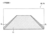
平坦路において運転者に視認されるAR表示の一例を示す図である。
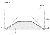
坂道において運転者に視認されるAR表示の一例を示す図である。
坂道における車両の状態と、道路勾配及び車両勾配の関係とを示す図である。
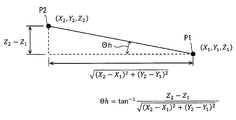
3次元地図データから道路勾配を算出する方法の一例を示す図である。
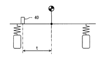
車高センサの計測情報に、車両のロール角が影響することを示す図である。
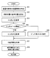
車高センサの出力値からピッチ角を算出する処理の詳細を示すフローチャートである。
加速時における車高センサの変位量とピッチ角との相関を模式的に示す図である。
減速時における車高センサの変位量とピッチ角との相関を模式的に示す図である。
表示光像の投影位置を道路勾配及び車両姿勢に合わせて補正する処理の詳細を示すフローチャートである。
図1に示す本開示の一実施形態による表示制御装置100は、車両において用いられる虚像表示システム110に適用されている。虚像表示システム110は、車両に関連する種々の情報を、車両の前景に重畳される虚像Viを用いて運転者に提示する。虚像表示システム110は、光学ユニット10及び表示制御装置100等を組み合わせることによって構成されている。
光学ユニット10は、車両に搭載された複数の表示器のうちの一つであって、表示制御装置100に電気的に接続されている。光学ユニット10は、車両のウィンドシールドWSに規定された投影領域PAに表示光像の光を投影し、表示光像の虚像Viを車両の搭乗者(例えば運転者)から視認可能に表示する。光学ユニット10は、虚像Viを表示するための構成として、プロジェクタ11及び反射光学系12を有している。
プロジェクタ11は、虚像Viとして結像される表示光像の光を、反射光学系12へ向けて射出する。反射光学系12は、プロジェクタ11から入射した表示光像の光を投影領域PAに投影する。ウィンドシールドWSに投影された光は、投影領域PAによってアイポイント側へ向けて反射され、運転者によって知覚される。尚、投影領域PAは、ウィンドシールドWSとは別体で設けられたコンバイナ等の投影部材に規定されてもよい。
表示制御装置100は、車両に搭載された表示器による表示を制御する電子制御ユニットである。表示制御装置100は、光学ユニット10による虚像表示を制御するための機能の一つとして、車両の姿勢を検出する機能を有している。表示制御装置100は、後述するように、車両の姿勢変化に合わせて表示光像の投影位置及び投影形状を補正し、前景中の適切な位置に適切な形状の虚像Viが結像されるよう制御する(図4参照)。表示制御装置100は、車両姿勢の検出に必要な情報を取得するため、自車位置検出装置21、3次元地図データベース22、車速センサ24、操舵角センサ26、乗員検知センサ27及び車高センサ40等と直接的又は間接的に電気接続されている。
自車位置検出装置21は、複数の人工衛星からの測位信号を受信する。自車位置検出装置21は、GPS、GLONASS、Galileo、IRNSS、QZSS、Beidou等の衛星測位システムのうちで、少なくとも一つの衛星測位システムの各測位衛星から、測位信号を受信可能である。自車位置検出装置21は、受信した測位信号に基づき、車両の位置を計測する。自車位置検出装置21は、計測した車両の位置情報を表示制御装置100へ向けて逐次出力する。
3次元地図データベース(以下、「3次元地図DB」)22は、多数の3次元地図データ及び2次元地図データを格納した大容量の記憶媒体を主体とする構成である。3次元地図データは、車両の自動運転を可能にする高精度な地図データである。3次元地図データでは、地形及び構造物が3次元の座標情報を持った点群によって表現されている。3次元地図DB22は、ネットワークを通じて、3次元地図データを最新の情報に更新可能である。3次元地図DB22は、表示制御装置100からの要求に応じて、車両の周辺及び進行方向の3次元地図データを表示制御装置100に提供可能である。尚、提供を要求されたエリアの3次元地図データが未整備である場合、3次元地図DB22は、ナビゲーション等に用いられる通常の2次元地図データを表示制御装置100に提供する。
車速センサ24及び操舵角センサ26は、車両の状態を検出する状態検出センサである。車速センサ24は、例えば車両の車輪の回転速度を検出する。車速センサ24は、車輪の回転速度を示す信号を表示制御装置100へ向けて逐次出力する。操舵角センサ26は、例えばステアリングシャフトの回転方向及び回転角度を検出する。回転角度は、直進時の角度位相(0°)が基準とされている。操舵角センサ26は、基準位置からの回転方向及び回転角度(ステアリング角)を示す信号を表示制御装置100へ向けて逐次出力する。
乗員検知センサ27は、車両に搭乗している搭乗者数を計測するためのセンサである。乗員検知センサ27は、運転席、助手席及び後部座席等の各着座面に配置されている。乗員検知センサ27は、例えば荷重の印加によってオン及びオフが切り替わるスイッチであり、各着座面への搭乗者の着座を検知する。乗員検知センサ27による検知結果は、車両のどの座席に乗員が着座しているかを示す情報となり、表示制御装置100によって逐次取得される。
図2に示す車高センサ40は、車両が置かれた路面からボディまでの高さを計測するため、車両に生じる上下方向の変位を検出するセンサである。車高センサ40は、ボディに懸架されたサスペンションアームの動作によって上下方向に変位する特定の車輪について、ボディに対する沈み込み量を計測する。具体的に、車高センサ40は、ボディとサスペンションアームとの間の相対距離を計測情報として取得し、表示制御装置100へ向けて逐次出力する。車高センサ40は、車両の前後方向にて中央よりも後方に一つだけ取り付けられており、車両後部での上下方向の変位を計測する。車高センサ40は、右ハンドル車両の場合、左リヤのサスペンションに取り付けられており、左ハンドル車両の場合、右リヤのサスペンションに取り付けられている。尚、上記の上下方向は、重力の向きに沿った鉛直方向とする。
車高センサ40は、第一連結部41、第二連結部42及び計測部43を有している。第一連結部41は、第二連結部42に対して相対回転可能である。第一連結部41は、ボディ及びサスペンションアームのうちの一方(例えばボディ側)に連結されている。第一連結部41は、一例としてボディのサブフレームSFに取り付けられている。
第二連結部42は、ボディ及びサスペンションアームのうちで、第一連結部41と連結されていない他方(例えばサスペンション側)に連結されている。第二連結部42は、懸架装置において車輪を支持する複数の支持要素のうちで、例えばロアアームLAに取り付けられている。
計測部43は、サブフレームSFに対するロアアームLAの上下方向の変位量を計測する。詳記すると、ロアアームLAの揺動に伴い、第一連結部41は、第二連結部42に対して相対回転する。計測部43は、ロアアームLAの上下方向の変位量として、第一連結部41の相対回転量を計測する。計測部43は、一例として磁石及びホール素子を有する構成であり、第一連結部41の回転に伴う磁束の変化を、ホール素子によって検出する。尚、計測部43は、発光ダイオード及びフォトトランジスタを組み合わせた構成により、第一連結部41の相対回転量を計測してもよい。車高センサ40は、計測部43の出力値を計測情報として表示制御装置100に逐次提供する。
表示制御装置100は、図1に示すように、処理部61、RAM62、メモリ装置63及び入出力インターフェースを有するコンピュータを主体に構成された電子制御ユニットである。処理部61は、CPU(Central Processing Unit)、GPU(Graphics Processing Unit)及びFPGA(Field-Programmable Gate Array)等の少なくとも一つを含む構成である。処理部61には、AI(Artificial Intelligence)の学習及び推論に特化した専用のプロセッサが含まれていてもよい。
メモリ装置63には、処理部61によって実行される種々のプログラムが格納されている。メモリ装置63に記憶された複数のプログラムには、虚像Viの表示を制御する表示制御プログラムが含まれている。表示制御プログラムは、図3及び図4に示すように、前景中の重畳対象に虚像Viを重ねてなる拡張現実(以下、「AR(Augmented Reality)」)表示を実現するプログラムである。一例として、表示制御プログラムは、走行中の車線の範囲を示す虚像Viを、前景中における左右の区画線CLの間に重畳表示する。
ここで、投影領域PAを通して運転者に視認される路面の形状は、車両が平坦路を走行している場合と、車両が坂道を登坂している場合とで異なってくる。一例として、水平基準平面HRPに沿った傾斜の無い平坦路を車両が走行している場合、道路勾配Θh及び車両勾配φaは、共に同一であって、実質的にゼロとなる。一方、水平基準平面HRPに対して傾斜した坂道を車両が走行している場合(図5参照)、車両勾配φaは、道路勾配Θhとは異なった値となる。具体的には、車両に生じたピッチ角を道路勾配Θhに加えた値が、車両勾配φaとなる。尚、水平基準平面HRPは、重力の方向に対して直交する仮想平面である。
以上によれば、坂道にて表示光像の投影位置及び投影形状の補正が実施されない場合、重畳対象からずれた虚像Vix(図4参照)が表示され得る。表示制御プログラムは、表示光像の投影位置及び投影形状を、道路勾配Θh及び車両の姿勢変化等に合わせて適切に制御するため、上記の道路勾配Θh、車両に生じているピッチ角及びロール角、並びに水平基準平面HRPに対する車両勾配φa等を演算する。
図1に示す表示制御装置100は、上記の表示制御プログラムの実行により、情報処理部71、勾配算出部72、ロール角演算部74、状態推定部75、姿勢検出部76及び表示制御部77等の機能ブロックを有する。
情報処理部71は、サブフレームSF及びロアアームLA(図2参照)間の相対距離を示す計測情報として、車高センサ40の出力値を取得する。加えて情報処理部71は、上下方向の変位を車両に生じさせる負荷が作用していない無負荷状態を、状態推定部73から取得する状態情報に基づき検知する。情報処理部71は、無負荷状態での車高センサ40の出力値を、ピッチ角及びロール角がゼロの状態を示す車高センサ40の初期値(基準値V0)として設定する。
勾配算出部72は、車速センサ24から入力される回転速度を示す信号に基づき、車速情報を取得する。勾配算出部72は、車速情報と、自車位置検出装置21から取得する車両の位置情報と、3次元地図DB22から取得する3次元地図データとを用いて、車両の現在位置を特定する。詳記すると、自車位置検出装置21から取得する位置情報には、概ね一定の遅延時間(100~200ミリ秒)が発生している。勾配算出部72は、位置情報に対して、遅延時間のうちに車両が移動した距離分を車速情報に基づいて地図上で補正し、車両の現在位置を特定する。
勾配算出部72は、特定した車両の現在位置に基づき、3次元地図DB22から取得した3次元地図データを用いて、車両が走行する道路の道路勾配Θh(図5参照)を算出する。道路勾配Θhは、道路の縦断勾配を示す勾配情報であり、上りの坂道では正の値をとり、下りの坂道では負の値をとる。一例として勾配算出部72は、図6に示すように、3次元地図データに含まれる点群の情報から、坂道を規定する二点P1,P2の緯度、経度及び高度を示した各座標(図6の(X,Y,Z)参照)を特定する。そして、勾配算出部72は、二点P1,P2の各座標を用いた幾何計算により、坂道の道路勾配Θhを取得する。
ロール角演算部74は、車両のロール角ψに関連する姿勢情報として、車両の走行速度vを示す車速情報と、車両が走行する道路のカーブ半径rを示すカーブ情報とを取得する。ロール角演算部74は、車速センサ24から入力される回転速度を示す信号に基づき、車速情報を取得する。加えてロール角演算部74は、操舵角センサ26から入力される回転方向及び回転角度を示す信号に基づき、操舵輪(前輪)の実舵角Aを算出し、下記の数式に基づいてカーブ半径rを推定する。尚、定数Wは車両のホイールベースの長さであり、メモリ装置63から読み出される値である。


状態推定部75は、車速情報及び舵角情報に加えて、ブレーキペダルへの操作を示すブレーキ踏力情報等を取得する。状態推定部75は、これらの情報を組み合わせて、上下方向の変位を生じさせるような負荷が車両に作用していない無負荷状態であるか否かを判定する。前後方向の加速度及びフレーキ力等が共に作用していない場合、ピッチ角及びロール角は、共に実質的にゼロとなる。車両の無負荷状態を示す状態情報は、情報処理部71に提供され、基準値V0の設定に用いられる。尚、無負荷状態の判定には、他の車載センサの情報、例えばアクセル開度情報及び前後方向の加速度情報等が用いられてもよい。
姿勢検出部76は、車高センサ40の出力値に基づき、車両のピッチ角θを算出する処理を繰り返し実施する(図8参照)。車高センサ40の出力値が示す上下方向の変位量には、ピッチ角による変位分だけでなく、ロール角による変位分が含まれている。姿勢検出部76は、車高センサ40にて計測された変位量から、ロール運動に伴う上下方向の変位分(以下、「変位量uψ」)を除いたうえで、ピッチ角θを演算する。
まず姿勢検出部76は、ロール角演算部74にて演算さいれたロール角ψの値を取得する(図8 S11)。そして姿勢検出部76は、取得したロール角ψの値を用いて、下記の数式に基づき、ロール角ψによる車高センサ40の変位量uψを演算する(図8 S12)。下記の数式における定数tは、車両の幅方向の中心から車高センサ40の取り付け位置までの距離であり(図7参照)、メモリ装置63から読み出される。




以上のように、車両の加速時において上下方向に生じる単位変位量に対応するピッチ角θ+は、減速時における単位変位量に対応するピッチ角θ-と異なっている。車高センサ40が車両の後部に設置されている場合、加速時における単位変位量に対応するピッチ角θ+は、減速時における単位変位量に対応するピッチ角θ-よりも小さくなる。換言すれば、車両のピッチ角θ+,θ-の絶対値が同一であったとしても、加速時に計測される変位量uθは、減速時に計測される変位量uθよりも大きくなる。
そして、上記の数式(数6)を変形することにより、加速時及び減速時のそれぞれにおいて、変位量uθからピッチ角θを算出する下記の数式が得られる。下記の数式における定数c+,c-,d+,d-は、試験又は計算等によって予め設定された較正値である。加速時の定数c+は、減速時の定数c-よりも小さな値とされている(c+<c-)。姿勢検出部76は、下記の数式に基づき、加速時及び減速時におけるピッチ角θを算出する(図8 S15)。

詳記すると、表示制御部77は、3次元地図データ、及び車両に搭載されたカメラ等の外界センサの認識情報等に基づき、虚像Viを重畳させる重畳対象の相対位置を特定する(図11 S21)。表示制御部77は、取得した重畳対象の相対位置、及び予め規定された運転者のアイリプス及び投影領域PAの各位置の関係に基づき、投影領域PAにて表示光像の光を投影する投影位置を、幾何学的な演算によって設定する(図11 S22)。表示制御部77は、道路勾配Θh(図5参照)が実質的にゼロであり、且つ、ロール及びピッチのいずれも生じていない場合の表示光像の投影位置を、基準位置として設定する。
加えて表示制御部77は、ロール角演算部74にて演算さいれたロール角ψの値を取得する(図11 S23)。表示制御部77は、取得したロール角ψの値が予め設定された上限値を超えているか否かを判定する(図11 S24)。ロール角ψが上限値以下であれば、表示制御部77は、姿勢検出部76にて演算された最新のピッチ角θの値を取得する。
表示制御部77は、車両のピッチ角θと勾配算出部72から取得する勾配情報とを用いて、車両勾配φa(図5参照)を算出する。加えて表示制御部77は、ロール角ψを用いて、ロール運動に伴う投影領域PAの上下方向のずれ分を算出する。表示制御部77は、車両勾配φaと投影領域PAの上下方向のずれ分とを補正情報として、投影位置を補正する演算を行う(図11 S27)。表示制御部77は、補正後の投影位置に表示光像が投影されるように、各フレームでの元画像の描画位置を設定する。
一方で、車両のロール角ψが上限値を超えている場合、表示制御部77は、ピッチ角θを強制的にゼロに設定する(図11 S24)。以上により、投影位置の補正が中止される。上限値は、一例として、運転者から見た虚像Viの縦方向の表示画角θvに基づき規定されている。ロール角ψの拡大によれば、運転者から見た重畳対象は、虚像Viを重畳できる範囲から外れる。具体的に、投影領域PAの上下方向の移動量は、車両の幅方向の中心から投影領域PAまでの幅方向の水平距離と、ロール角ψとの積となる。一方で、表示光像の投影される投影範囲の上下方向の寸法は、アイリプスの中心から投影領域PAまでの距離と、表示画角θvとの積となる。故に、ロールに伴う投影領域PAの上下方向の移動量が、投影範囲の上下方向の寸法を超えていた場合、投影位置を補正したとしても、虚像Viは、重畳対象に対して重畳されなくなる。そのため、表示画角θvから幾何学的に算出した上限値を用いれば、表示制御部77は、補正不可能な状態に達するタイミングで投影位置の補正を適確に中止させ、基準位置への投影に切り替えさせることができる。
ここまで説明した本実施形態では、表示光像の投影位置が、3次元地図データに基づく勾配情報と、一つの車高センサ40にて計測された計測情報とによって補正される。故に、車両の姿勢を計測するための複数のセンサ又は複雑な構成は、不要となり得る。したがって、車両姿勢を検出する構成の複雑化を回避しつつ、重畳対象に対する虚像表示のずれの低減が可能になる。
ここで、車両の上下方向への変位には、ピッチ運動に起因する変位分と、ロール運動に起因する変位分とが含まれる。故に本実施形態では、車高センサ40の出力値に基づく全変位量から、ロール角による変位量uψが差し引かれる。以上によれば、車両姿勢を一つの車高センサ40で把握する形態であっても、投影位置は、車両のピッチ角θに合わせて適確に補正され得る。以上によれば、ロールが発生するようなカーブ走行中においても、虚像Viは、重畳対象に精度良く重畳表示され続ける。
一方で、車両のロール角ψの拡大によれば、投影位置を補正可能な範囲を超える場合が想定される。そのため本実施形態では、車両のロール角ψが上限値を超えた場合には、投影位置の補正が中止される。以上によれば、重畳対象に無理に重畳させようとする虚像Viの挙動が運転者に煩わしさを感じさせてしまう事態は、回避される。
また本実施形態では、車速情報及びカーブ情報に基づき、ロール角ψが推定される。これらの値は、一般的に車両に搭載されている車速センサ24及び操舵角センサ26を用いて取得可能である。故に、ロール角ψを鑑みて投影位置の補正を行う形態であっても、車両姿勢を検出する構成の複雑化は、回避される。
さらに本実施形態では、投影位置の補正を中止するロール角の上限値が、虚像Viの縦方向の表示画角θvに基づき規定されている。表示画角θvが大きくなるほど、表示光像の投影位置を上下方向に調整する調整代が大きく確保できる。故に、補正中止を判定する上限値が表示画角θvに基づき規定されれば、光学ユニットの性能を有効に利用しつつ、適切なロール角ψで補正中止を決定することが可能になる。
加えて本実施形態では、変位量uθからピッチ角θを算出する処理にて、加速時における単位変位量に対応するピッチ角θ+が、減速時における単位変位量に対応するピッチ角θ-と異なっている。以上のように、車両の姿勢変化の特性を鑑みて、適用する数式を切り替える処理によれば、一つの車高センサ40のみで姿勢変化を検出する形態であっても、表示制御装置100は、計測した変位量uθから適切なピッチ角θを算出できる。
具体的に、本実施形態では、車高センサ40が車両の後部に取り付けられている。こうした形態では、加速時における単位変位量に対応するピッチ角θ+を、減速時における単位変位量に対応するピッチ角θ-よりも小さくすれば、表示制御装置100は、変位量uθからピッチ角θを精度良く算出できる。
さらに本実施形態では、無負荷状態での出力値を基準として、車高計測センサの初期値が設定される。こうした設定であれば、搭乗者の人数及び積載物が変化した場合でも、車高センサ40の出力値の変化から、走行時の姿勢変化に伴うピッチ角θの変化を精度良く算出することが可能になる。
尚、本実施形態では、情報処理部71が「計測情報取得部」に相当し、勾配算出部72が「勾配情報取得部」に相当し、ロール角演算部74が「姿勢情報取得部」に相当し、姿勢検出部76及び表示制御部77が協働で「位置設定部」に相当する。
(他の実施形態)
以上、本開示の一実施形態について説明したが、本開示は、上記実施形態に限定して解釈されるものではなく、本開示の要旨を逸脱しない範囲内において種々の実施形態及び組み合わせに適用することができる。
以上、本開示の一実施形態について説明したが、本開示は、上記実施形態に限定して解釈されるものではなく、本開示の要旨を逸脱しない範囲内において種々の実施形態及び組み合わせに適用することができる。
上記実施形態では、車高センサにて計測された全変位量から、ロール角による変位分が差し引かれていた。しかし、上記実施形態の変形例1では、ロール角を補正する処理が省略されている。変形例1の姿勢検出部では、下記の数式に基づき、車高センサの出力値Vからピッチ角θ+,θ-が算出される。ピッチ角θ+を算出する式は、V-V0>0の場合に適用され、ピッチ角θ-を算出する式は、V-V0<0の場合に適用される。

上記実施形態では、ロール角を算出するためのカーブ半径が、実舵角及びホイールベースの各値に基づいて算出されていた。しかし、車両にヨーレートセンサが搭載された形態であれば、ヨーレートセンサの出力値(ヨー角)に基づいてカーブ半径が算出されてもよい。さらに、カーブ半径は、3次元地図データから抽出されてもよい。
上記実施形態では、ロール角が上限値を超えた時点で、投影位置の補正が中断されていた。このとき、表示光像の投影位置は、基準位置に戻されなくてもよい。光学ユニットは、投影位置を最大限に移動させた状態で、表示光像の投影を継続させてもよい。また、ロール角の増加に伴う投影位置の補正の中止は、実施されなくてもよい。さらに、補正中止の閾値となる上限値は、適宜変更されてよい。
上記実施形態では、変位量からピッチ角を算出する処理にて、加速時に用いられる数式と、減速時に用いられる数式とが互いに異なっていた。しかし、加速時と減速時とで共通の数式が用いられてもよい。さらに、車高センサが車両の前方に設置されている場合、加速時における単位変位量に対応するピッチ角は、減速時における単位変位量に対応するピッチ角よりも大きくされてよい。
上記実施形態では、映像データの各フレームで元画像を補正する処理により、重畳対象に虚像Viを重ねた表示が維持されていた。しかし、反射光学系の姿勢を調整する調整機構が光学ユニットに設けられていれば、補正情報に基づいて調整機構を作動させる機械的な制御により、虚像Viの重畳状態が維持されてもよい。
ここまで説明した表示制御のための処理は、上記の表示制御装置とは異なる構成によって実施されてもよい。例えば表示制御装置は、コンビネーションメータ及びナビゲーション装置等に含まれる構成であってもよい。即ち、コンビネーションメータ及びナビゲーション装置が、上述の表示制御プログラムを制御回路にて実行することにより、表示制御装置の機能を獲得してもよい。さらに、上記実施形態の姿勢検出部にて実施されていた姿勢検出のための演算は、車両に搭載された複数の制御装置の制御回路によって分散処理されてもよい。
さらに、フラッシュメモリ及びハードディスク等の種々の非遷移的実体的記憶媒体(non-transitory tangible storage medium)が表示制御プログラムを格納する構成として、メモリ装置に採用可能である。加えて、表示制御プログラムを記憶する記憶媒体は、車載された電子制御ユニットに設けられた記憶媒体に限定されず、当該記憶媒体へのコピー元となる光学ディスク及び汎用コンピュータのハードディスクドライブ等であってもよい。
本開示に記載されるフローチャート、あるいは、フローチャートの処理は、複数の部(あるいはステップと言及される)から構成され、各部は、たとえば、S101と表現される。さらに、各部は、複数のサブ部に分割されることができる、一方、複数の部が合わさって一つの部にすることも可能である。さらに、このように構成される各部は、サーキット、デバイス、モジュール、ミーンズとして言及されることができる。
また、上記の複数の部の各々あるいは組合わさったものは、(i) ハードウエアユニット(例えば、コンピュータ)と組み合わさったソフトウェアの部のみならず、(ii) ハードウエア(例えば、集積回路、配線論理回路)の部として、関連する装置の機能を含みあるいは含まずに実現できる。さらに、ハードウェアの部は、マイクロコンピュータの内部に構成されることもできる。
Claims (10)
- 光学ユニット(10)から投影領域(PA)への表示光像の投影によって車両の前景に重畳される虚像(Vi)の表示を制御する表示制御装置であって、
前記虚像を重畳させる重畳対象の相対位置に基づき、前記投影領域に投影される前記表示光像の投影位置を設定する位置設定部(76,77)と、
前記車両に生じる上下方向の変位を計測する一つの車高センサ(40)から計測情報を取得する計測情報取得部(71)と、
3次元地図データに基づき、前記車両が走行する道路の勾配を示した勾配情報を取得する勾配情報取得部(72)と、を備え、
前記位置設定部は、前記計測情報及び前記勾配情報に基づき、前記表示光像の前記投影位置を補正する表示制御装置。 - 前記車両のロール角に関連する姿勢情報を取得する姿勢情報取得部(74)、をさらに備える請求項1に記載の表示制御装置。
- 前記位置設定部は、前記計測情報に含まれる前記車両のロール運動に伴う上下方向の変位分を、前記姿勢情報を用いて補正する請求項2に記載の表示制御装置。
- 前記位置設定部は、前記姿勢情報の示す前記ロール角が予め規定された上限値を超えた場合に、前記投影位置の補正を中止する請求項2又は3に記載の表示制御装置。
- 前記姿勢情報取得部は、前記車両の走行速度を示す車速情報と、前記車両が走行する道路のカーブ半径を示すカーブ情報とを、前記姿勢情報として取得し、
前記位置設定部は、前記車速情報及び前記カーブ情報に基づき推定される前記ロール角が前記上限値を超えると判定した場合に、前記投影位置の補正を中止する請求項4に記載の表示制御装置。 - 前記上限値は、前記光学ユニットにおける前記虚像の上下方向の表示画角(θv)に基づき規定されている請求項4又は5に記載の表示制御装置。
- 前記位置設定部は、前記計測情報が示す上下方向の変位量に基づき、前記車両のピッチ角を算出し、
前記車両の加速時において上下方向に生じる単位変位量に対応するピッチ角は、減速時における前記単位変位量に対応するピッチ角と異なる請求項1~6のいずれか一項に記載の表示制御装置。 - 前記車高センサは、前記車両の前後方向にて中央よりも後方で上下方向の変位を計測し、
加速時における前記単位変位量に対応するピッチ角は、減速時における前記単位変位量に対応するピッチ角よりも小さい請求項7に記載の表示制御装置。 - 前記計測情報取得部は、上下方向の変位を前記車両に生じさせる負荷が作用していない無負荷状態での前記車高センサの出力値を、この車高センサの基準値とする請求項1~8のいずれか一項に記載の表示制御装置。
- 光学ユニット(10)から投影領域(PA)への表示光像の投影によって車両の前景に重畳される虚像(Vi)の表示を制御する表示制御プログラムであって、
少なくとも一つの処理部(61)を
前記虚像を重畳させる重畳対象の相対位置に基づき、前記投影領域に投影される前記表示光像の投影位置を設定する位置設定部(76,77)、
前記車両に生じる上下方向の変位を計測する一つの車高センサ(40)から計測情報を取得する計測情報取得部(71)、
3次元地図データに基づき、前記車両が走行する道路の勾配を示した勾配情報を取得する勾配情報取得部(72)、として機能させ、
前記位置設定部は、前記計測情報及び前記勾配情報に基づき、前記表示光像の前記投影位置を補正する表示制御プログラム。
Priority Applications (1)
| Application Number | Priority Date | Filing Date | Title |
|---|---|---|---|
| US16/867,974 US11264000B2 (en) | 2017-11-10 | 2020-05-06 | Display control device and non-transitory computer readable medium |
Applications Claiming Priority (2)
| Application Number | Priority Date | Filing Date | Title |
|---|---|---|---|
| JP2017-217468 | 2017-11-10 | ||
| JP2017217468A JP6787297B2 (ja) | 2017-11-10 | 2017-11-10 | 表示制御装置、及び表示制御プログラム |
Related Child Applications (1)
| Application Number | Title | Priority Date | Filing Date |
|---|---|---|---|
| US16/867,974 Continuation US11264000B2 (en) | 2017-11-10 | 2020-05-06 | Display control device and non-transitory computer readable medium |
Publications (1)
| Publication Number | Publication Date |
|---|---|
| WO2019092995A1 true WO2019092995A1 (ja) | 2019-05-16 |
Family
ID=66439179
Family Applications (1)
| Application Number | Title | Priority Date | Filing Date |
|---|---|---|---|
| PCT/JP2018/035273 Ceased WO2019092995A1 (ja) | 2017-11-10 | 2018-09-25 | 表示制御装置、及び表示制御プログラム |
Country Status (3)
| Country | Link |
|---|---|
| US (1) | US11264000B2 (ja) |
| JP (1) | JP6787297B2 (ja) |
| WO (1) | WO2019092995A1 (ja) |
Cited By (2)
| Publication number | Priority date | Publication date | Assignee | Title |
|---|---|---|---|---|
| WO2020241094A1 (ja) * | 2019-05-31 | 2020-12-03 | パナソニックIpマネジメント株式会社 | 表示システム |
| WO2021020385A1 (ja) * | 2019-07-30 | 2021-02-04 | 株式会社デンソー | 表示制御装置 |
Families Citing this family (8)
| Publication number | Priority date | Publication date | Assignee | Title |
|---|---|---|---|---|
| JP6756327B2 (ja) * | 2017-11-10 | 2020-09-16 | 株式会社Soken | 姿勢検出装置、及び姿勢検出プログラム |
| JP7087564B2 (ja) * | 2018-03-29 | 2022-06-21 | トヨタ自動車株式会社 | カント推定方法 |
| JP7063856B2 (ja) * | 2019-07-30 | 2022-05-09 | 株式会社Soken | 表示制御装置 |
| DE102020107802A1 (de) * | 2020-03-20 | 2021-09-23 | Horiba Europe Gmbh | Test-System zum Testen einer LIDAR-Vorrichtung |
| JP7034225B1 (ja) * | 2020-09-25 | 2022-03-11 | 日立建機株式会社 | 鉱山機械 |
| DE112020007542T5 (de) * | 2020-10-19 | 2023-08-17 | Ford Global Technologies, Llc | Aufhängungssystem mit elektronischer nickstabilitätssteuerung |
| JP7318669B2 (ja) * | 2021-01-27 | 2023-08-01 | セイコーエプソン株式会社 | 表示方法および表示システム |
| JP7661084B2 (ja) * | 2021-03-30 | 2025-04-14 | 本田技研工業株式会社 | 学習装置、学習方法、プログラム、および物体検知装置 |
Citations (3)
| Publication number | Priority date | Publication date | Assignee | Title |
|---|---|---|---|---|
| JPH0952555A (ja) * | 1995-08-11 | 1997-02-25 | Mitsubishi Electric Corp | 周辺監視装置 |
| JP2010256878A (ja) * | 2009-03-30 | 2010-11-11 | Equos Research Co Ltd | 情報表示装置 |
| JP2016004448A (ja) * | 2014-06-18 | 2016-01-12 | 株式会社デンソー | 運転支援装置、運転支援方法、画像補正装置、画像補正方法 |
Family Cites Families (12)
| Publication number | Priority date | Publication date | Assignee | Title |
|---|---|---|---|---|
| JPH0893828A (ja) * | 1994-09-27 | 1996-04-12 | Toyota Motor Corp | 油圧緩衝器 |
| JP3765862B2 (ja) * | 1996-02-15 | 2006-04-12 | 本田技研工業株式会社 | 車両用環境認識装置 |
| JP3384236B2 (ja) * | 1996-04-22 | 2003-03-10 | 株式会社デンソー | 車両用前照灯光軸方向自動調整装置 |
| JP2006292969A (ja) * | 2005-04-08 | 2006-10-26 | Fujinon Corp | 像振れ補正装置 |
| JP5131682B2 (ja) * | 2007-08-07 | 2013-01-30 | 本田技研工業株式会社 | 可変減衰力ダンパの制御装置 |
| JP5161760B2 (ja) * | 2008-12-26 | 2013-03-13 | 株式会社東芝 | 車載用表示システム及び表示方法 |
| JP5327025B2 (ja) | 2009-12-03 | 2013-10-30 | アイシン・エィ・ダブリュ株式会社 | 車両用走行案内装置、車両用走行案内方法及びコンピュータプログラム |
| EP2543541B1 (en) | 2011-07-04 | 2019-02-27 | Mitsubishi Jidosha Kogyo Kabushiki Kaisha | Optical axis controller of automotive headlamp |
| JP5691892B2 (ja) * | 2011-07-04 | 2015-04-01 | 三菱自動車工業株式会社 | 車載ヘッドランプの光軸制御装置 |
| US9162569B2 (en) * | 2013-07-30 | 2015-10-20 | Arvinmeritor Technology, Llc | Method of controlling a differential lock |
| JP6040897B2 (ja) | 2013-09-04 | 2016-12-07 | トヨタ自動車株式会社 | 注意喚起表示装置及び注意喚起表示方法 |
| JP6669199B2 (ja) | 2017-07-18 | 2020-03-18 | 株式会社Soken | センサ校正装置、及びセンサ校正プログラム |
-
2017
- 2017-11-10 JP JP2017217468A patent/JP6787297B2/ja not_active Expired - Fee Related
-
2018
- 2018-09-25 WO PCT/JP2018/035273 patent/WO2019092995A1/ja not_active Ceased
-
2020
- 2020-05-06 US US16/867,974 patent/US11264000B2/en active Active
Patent Citations (3)
| Publication number | Priority date | Publication date | Assignee | Title |
|---|---|---|---|---|
| JPH0952555A (ja) * | 1995-08-11 | 1997-02-25 | Mitsubishi Electric Corp | 周辺監視装置 |
| JP2010256878A (ja) * | 2009-03-30 | 2010-11-11 | Equos Research Co Ltd | 情報表示装置 |
| JP2016004448A (ja) * | 2014-06-18 | 2016-01-12 | 株式会社デンソー | 運転支援装置、運転支援方法、画像補正装置、画像補正方法 |
Cited By (6)
| Publication number | Priority date | Publication date | Assignee | Title |
|---|---|---|---|---|
| WO2020241094A1 (ja) * | 2019-05-31 | 2020-12-03 | パナソニックIpマネジメント株式会社 | 表示システム |
| JPWO2020241094A1 (ja) * | 2019-05-31 | 2020-12-03 | ||
| US11945310B2 (en) | 2019-05-31 | 2024-04-02 | Panasonic Intellectual Property Management Co., Ltd. | Display system |
| JP7535758B2 (ja) | 2019-05-31 | 2024-08-19 | パナソニックIpマネジメント株式会社 | 表示システム |
| WO2021020385A1 (ja) * | 2019-07-30 | 2021-02-04 | 株式会社デンソー | 表示制御装置 |
| JP2021020625A (ja) * | 2019-07-30 | 2021-02-18 | 株式会社Soken | 表示制御装置 |
Also Published As
| Publication number | Publication date |
|---|---|
| US11264000B2 (en) | 2022-03-01 |
| JP6787297B2 (ja) | 2020-11-18 |
| JP2019089354A (ja) | 2019-06-13 |
| US20200273435A1 (en) | 2020-08-27 |
Similar Documents
| Publication | Publication Date | Title |
|---|---|---|
| US11264000B2 (en) | Display control device and non-transitory computer readable medium | |
| US11301695B2 (en) | Orientation detection device and non-transitory computer readable medium | |
| JP6669199B2 (ja) | センサ校正装置、及びセンサ校正プログラム | |
| JP7063856B2 (ja) | 表示制御装置 | |
| JP6724885B2 (ja) | 虚像表示装置 | |
| US20210031776A1 (en) | Display control unit and non-transitory tangible computer readable storage medium | |
| JP2005256636A (ja) | 車両安定化制御システム | |
| JP6724886B2 (ja) | 虚像表示装置 | |
| WO2018070252A1 (ja) | 車両用映像表示装置 | |
| US12051345B2 (en) | Vehicular display control device | |
| JP7057327B2 (ja) | 表示制御装置 | |
| JP7450230B2 (ja) | 表示システム | |
| JP7843385B2 (ja) | 推定装置、制御方法、プログラム及び記憶媒体 | |
| JP2021088315A (ja) | 表示制御装置、表示制御プログラム及び虚像表示システム | |
| US11579612B2 (en) | Position and attitude estimation apparatus and position and attitude estimation method | |
| JP7211304B2 (ja) | 表示装置 | |
| JP7422322B2 (ja) | 姿勢角処理装置、画像表示システム、姿勢角処理方法及びプログラム | |
| JP6891863B2 (ja) | 表示制御装置および表示制御プログラム | |
| JP7417907B2 (ja) | 表示システム | |
| WO2025005031A1 (ja) | 移動体用表示システム | |
| WO2019017192A1 (ja) | センサ校正装置、及びセンサ校正プログラム | |
| JP2025017412A (ja) | 表示制御装置およびヘッドアップディスプレイ装置 | |
| JP2025014541A (ja) | 移動体用表示システム、及び表示制御装置 |
Legal Events
| Date | Code | Title | Description |
|---|---|---|---|
| 121 | Ep: the epo has been informed by wipo that ep was designated in this application |
Ref document number: 18875618 Country of ref document: EP Kind code of ref document: A1 |
|
| NENP | Non-entry into the national phase |
Ref country code: DE |
|
| 122 | Ep: pct application non-entry in european phase |
Ref document number: 18875618 Country of ref document: EP Kind code of ref document: A1 |