WO2019088240A1 - 圧縮機 - Google Patents
圧縮機 Download PDFInfo
- Publication number
- WO2019088240A1 WO2019088240A1 PCT/JP2018/040771 JP2018040771W WO2019088240A1 WO 2019088240 A1 WO2019088240 A1 WO 2019088240A1 JP 2018040771 W JP2018040771 W JP 2018040771W WO 2019088240 A1 WO2019088240 A1 WO 2019088240A1
- Authority
- WO
- WIPO (PCT)
- Prior art keywords
- recess
- fixed
- partition wall
- compressor
- compression chamber
- Prior art date
- Legal status (The legal status is an assumption and is not a legal conclusion. Google has not performed a legal analysis and makes no representation as to the accuracy of the status listed.)
- Ceased
Links
Images


Classifications
-
- F—MECHANICAL ENGINEERING; LIGHTING; HEATING; WEAPONS; BLASTING
- F04—POSITIVE - DISPLACEMENT MACHINES FOR LIQUIDS; PUMPS FOR LIQUIDS OR ELASTIC FLUIDS
- F04C—ROTARY-PISTON, OR OSCILLATING-PISTON, POSITIVE-DISPLACEMENT MACHINES FOR LIQUIDS; ROTARY-PISTON, OR OSCILLATING-PISTON, POSITIVE-DISPLACEMENT PUMPS
- F04C18/00—Rotary-piston pumps specially adapted for elastic fluids
- F04C18/02—Rotary-piston pumps specially adapted for elastic fluids of arcuate-engagement type, i.e. with circular translatory movement of co-operating members, each member having the same number of teeth or tooth-equivalents
-
- F—MECHANICAL ENGINEERING; LIGHTING; HEATING; WEAPONS; BLASTING
- F04—POSITIVE - DISPLACEMENT MACHINES FOR LIQUIDS; PUMPS FOR LIQUIDS OR ELASTIC FLUIDS
- F04C—ROTARY-PISTON, OR OSCILLATING-PISTON, POSITIVE-DISPLACEMENT MACHINES FOR LIQUIDS; ROTARY-PISTON, OR OSCILLATING-PISTON, POSITIVE-DISPLACEMENT PUMPS
- F04C29/00—Component parts, details or accessories of pumps or pumping installations, not provided for in groups F04C18/00 - F04C28/00
- F04C29/12—Arrangements for admission or discharge of the working fluid, e.g. constructional features of the inlet or outlet
Definitions
- the present disclosure relates to a compressor that discharges fluid in multiple stages by discharging the movable scroll with respect to the fixed scroll.
- Patent Document 1 There are some compressors of this type described in Patent Documents 1 to 3.
- the compressor described in Patent Document 1 includes a movable scroll having a swirling wrap and a fixed scroll having a spiral fixed wrap.
- this compressor closes the appropriate position of the spiral groove formed by the fixed wrap in the fixed scroll with the partition wall, and provides the low-stage side discharge port and the high-stage side suction port on both sides of this partition wall.
- the pressurized gas discharged from the low stage side discharge port is led to the high stage side suction port.
- Patent Documents 2 to 3 an intermediate groove is provided in the partition wall, and an intermediate tip seal is inserted in the intermediate groove for preventing fluid leakage from the rear stage compression chamber to the front stage compression chamber. The machine is described.
- the high pressure side and the low pressure side compression chamber are formed in the compression chamber by blocking the flow path of the pressurized gas by the partition wall formed in the middle portion of the fixed wrap. It is formed.
- the compressor can be miniaturized by reducing the thickness of the partition wall.
- this compressor passes the gap between the partition wall and the movable scroll in the thrust direction.
- the pressurized gas leaks from the stage side to the lower stage side.
- the pressurized gas leaking from the partition wall tends to leak to the lower stage side suction chamber.
- the pressurized gas easily leaks from the high stage side to the low stage side through both the path from the outer peripheral lap groove to the intermediate groove and the path from the inner peripheral lap groove to the intermediate groove.
- the compressor efficiency is reduced, which leads to a reduction in capacity.
- the compressor described in Patent Document 3 is provided with a plurality of notches cut in the longitudinal direction on the side surface of the intermediate tip seal, and a backup ring made of an elastic material.
- a backup ring made of an elastic material.
- An object of the present disclosure is to achieve both downsizing of a compressor and improvement in efficiency.
- a fixed scroll having a spiral fixed toothed portion erected from a disk-shaped fixed base plate portion and a disk-shaped movable base plate are erected from one surface and fixed.
- a compressor including: a movable scroll having a spiral movable tooth portion meshing with a tooth portion; and a multistage compression and discharge of fluid by turning the movable scroll with respect to the fixed scroll;
- the partition wall which is erected toward the side of the part and which divides the spiral groove formed by the fixed teeth into the high-stage compression chamber and the low-stage compression chamber, and the tip of the partition wall
- a second sealing member for sealing a gap between the, between the first recess and the second recess, the partition wall separating
- the partition wall portion that separates the first recess from the second recess is provided between the first recess and the second recess, the second recess passes through the first recess. Since the leakage of fluid from the high stage side compression chamber to the low stage side compression chamber is suppressed, it is possible to achieve both the miniaturization of the compressor and the improvement of the efficiency.
- parenthesized reference symbol attached to each component etc. shows an example of the correspondence of the component etc. and the specific component etc. as described in the embodiment to be described later.
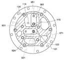
- FIG. 1 is a circuit diagram showing a schematic configuration of a refrigeration cycle to which a compressor according to a first embodiment is applied. It is a sectional view of a compressor of a 1st embodiment. It is the figure which drew the fixed scroll in the state which removed the discharge plate typically seeing from the downward side.
- FIG. 4 is a cross-sectional view taken along line IV-IV in FIG.
- FIG. 5 is a cross-sectional view taken along the line V-V in FIG. 4;
- FIG. 6 is a cross-sectional view taken along the line VI-VI in FIG. It is the figure which showed the state of the fixed tooth part and the movable substrate part to the turning angle of movable scroll.
- FIG. 4 It is a figure showing pressure X1, X2, X3, and X4 of each part to a turning angle of movable scroll. It is sectional drawing corresponding to FIG. 4 in the compressor of 2nd Embodiment. It is sectional drawing corresponding to FIG. 4 in the compressor of 3rd Embodiment. It is a figure for demonstrating the pressure difference of the high-stage side compression chamber of the one end side of a partition wall, and the low-stage side discharge port of the other end side of a partition wall. It is sectional drawing corresponding to FIG. 4 in the compressor of 4th Embodiment. It is a XIII-XIII sectional view in FIG. It is XIV-XIV sectional drawing in FIG. It is sectional drawing corresponding to FIG.
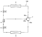
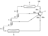
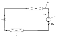
- the compressor 1 is applied to a heat pump cycle 100 that heats hot water with a heat pump type water heater. Therefore, the fluid compressed by the compressor 1 of the present embodiment is a refrigerant of the heat pump cycle.
- the heat pump cycle 100 is configured as a gas injection cycle in which the medium pressure gas phase refrigerant of the cycle is joined to the refrigerant in the middle of the compression process in the compression chamber 15 of the compressor 1.
- the heat pump cycle 100 of the present embodiment includes a compressor 1, a water-refrigerant heat exchanger 2, a first expansion valve 3, a gas-liquid separator 4, and a second expansion valve. 5 has an outdoor heat exchanger 6 and the like.
- the compressor 1 has a suction port 30a for sucking the refrigerant from the outdoor heat exchanger 6, an intermediate pressure suction port 30b for sucking the intermediate pressure from the gas-liquid separator 4, and a high pressure refrigerant discharge port 30c for discharging the compressed refrigerant. have.
- the compressor 1 compresses the refrigerant sucked from the suction port 30a and discharges it from the high pressure refrigerant discharge port 30c.
- the water-refrigerant heat exchanger 2 is a heating heat exchanger that heats the hot water supply by heat exchange between the refrigerant discharged from the high pressure refrigerant discharge port 30c of the compressor 1 and the hot water supply.
- the first expansion valve 3 is a high-stage pressure reducing section that reduces the pressure of the high pressure refrigerant flowing out of the water-refrigerant heat exchanger 2 to an intermediate pressure refrigerant, and is controlled by a control signal output from an electronic control unit (not shown) It is an electric expansion valve whose operation is controlled.
- the gas-liquid separator 4 is a gas-liquid separation unit that separates the gas-liquid of the intermediate pressure refrigerant decompressed by the first expansion valve 3.
- the second expansion valve 5 is a low-stage pressure reducing section for reducing the pressure of the intermediate pressure liquid phase refrigerant flowing out from the liquid phase refrigerant outlet of the gas liquid separator 4 to a low pressure refrigerant, and its basic configuration is the first The same as the expansion valve 3.
- the outdoor heat exchanger 6 is a heat absorbing heat exchanger that causes the low pressure refrigerant decompressed by the second expansion valve 5 to exchange heat with the outside air and evaporate it.
- the suction port 30a of the compressor 1 is connected to the refrigerant outlet side of the outdoor heat exchanger 6, and the intermediate pressure suction port 30b of the compressor 1 is connected to the gas phase refrigerant outlet of the gas-liquid separator 4. There is. Therefore, in the present embodiment, the intermediate pressure gas phase refrigerant separated by the gas liquid separator 4 is injected into the refrigerant in the middle of the compression process in the compression chamber 15 of the compressor 1.
- carbon dioxide is employed as the refrigerant, and the pressure of the high pressure side refrigerant of the cycle from the discharge port of the compressor 1 to the inlet side of the first expansion valve 3 becomes supercritical or more. It constitutes a refrigeration cycle. Furthermore, a lubricating oil (refrigerating machine oil) for lubricating each sliding portion inside the compressor 1 is mixed in the refrigerant, and a part of the lubricating oil circulates a cycle with the refrigerant.
- a lubricating oil refrigerating machine oil
- the heat pump type water heater is a hot water storage tank for storing hot water heated by the water-refrigerant heat exchanger 2, and hot water supply between the hot water storage tank and the water-refrigerant heat exchanger 2.
- a hot water circulation circuit for circulating water and a water pump (not shown) disposed in the hot water circulation circuit for pumping hot water are also provided.
- the compressor 1 is configured to include a scroll type two-stage compression mechanism in which a compression unit of one scroll compressor is divided into two stages.
- arrow DR1 of FIG. 2 has shown the up-down direction of the compressor 1. As shown in FIG.
- the compressor 1 of the present embodiment is disposed in the upper portion of the housing 30 and the scroll type two-stage compression mechanism portion 40 disposed in the lower portion of the housing 30, and the scroll type two-stage compression mechanism
- the electric motor 20 which is a drive source of the part 40 is provided.
- the electric motor is connected to a terminal provided on the housing 30 by a wire (not shown).
- the electric motor 20 has a rotor 22 and a stator 23, and a drive shaft 25 is integrally coupled to the rotor 22.
- the lower end of the drive shaft 25 is connected to the movable scroll 11 of the scroll type two-stage compression mechanism 40.
- the electric motor 20 drives the movable scroll 11 connected to the drive shaft 25.
- the scroll type two-stage compression mechanism unit 40 has a movable scroll 11 and a fixed scroll 12.
- the movable scroll 11 includes a disk-shaped movable substrate portion 111 and a spiral movable tooth portion 112 erected from one surface of the movable substrate portion 111 toward the fixed substrate portion 121.
- the fixed scroll 12 has a disk-shaped fixed substrate portion 121 and a spiral shaped fixed tooth portion 122 erected from the fixed substrate portion 121 toward the movable substrate portion 111 side.
- the fixed substrate portion 121 is fixed to the housing 30.
- the movable scroll 11 is disposed such that the movable tooth portion 112 meshes with the fixed tooth portion 122.
- the two substrate portions 111 and 121 are disposed to face each other in the vertical direction.
- the movable scroll 11 revolves around the center of rotation of the drive shaft 25 as a revolution center.
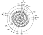
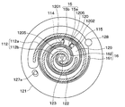
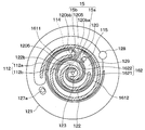
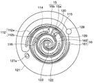
- a spiral groove 129 is formed on the surface of the fixed substrate portion 121 facing the movable substrate portion 111, and the side wall of the spiral groove 129 constitutes a spiral tooth portion 122. .
- a partition wall 120 is formed which divides the spiral groove 129 formed between the fixed tooth portions 122 at a predetermined location.
- the fixed scroll 12 is provided with a high pressure side compression chamber 15a communicating the spiral groove 129 with the high pressure side suction port 115 described later, and a low speed side communicating with the low pressure side discharge port 114 described later.
- a partition wall 120 is formed to divide into the compression chamber 15b. The partition wall 120 is erected from the fixed substrate portion 121 toward the movable substrate portion 111.
- the partition wall 120 connects the fixed tooth portion 122 located radially outside the fixed substrate portion 121 with respect to the partition wall 120, and the fixed tooth portion 122 located radially inward of the fixed substrate portion 121 with respect to the partition wall 120. doing.
- the side wall on the low stage side compression chamber 15b side is a curved surface
- the side wall on the high stage side compression chamber 15a side of the partition wall 120 is a curved surface.
- the high stage side compression chamber 15a is formed on the winding start side of the fixed tooth portion 122, and the low stage side compression chamber 15b is formed on the winding end side of the fixed tooth portion 122. That is, the high-stage compression chamber 15 a is formed on the center side of the compression chamber 15, and the low-stage compression chamber 15 b is formed radially outward from the compression chamber 15.
- the discharge plate 140 is a plate-like member attached to the lower surface of the fixed scroll 12 via a gasket 130.
- Each of the intermediate pressure chamber 981 and the high stage discharge chamber 924 described later is formed so as to straddle both the discharge plate 140 and the fixed scroll 12.
- the lower stage suction passage 901 is a passage for supplying the refrigerant to the lower stage compression chamber 15b.
- a pipe connected to the outdoor heat exchanger 6 is press-fit into the low stage suction flow passage 901, the illustration of the pipe is omitted in FIG.
- the pipe has a flange portion, and is connected to the cylindrical member 31 of the compressor housing housing by the flange portion, and the compressor is sealed.
- the pipe is identical to the suction port.
- the refrigerant supplied to the lower stage suction flow passage 901 flows into the lower stage compression chamber 15b through the refrigerant suction port 128 which is a through hole, and is then compressed in the lower stage compression chamber 15b.
- the intermediate pressure chamber 981 is formed as a flow path connecting the lower stage compression chamber 15b and the higher stage compression chamber 15a.
- the refrigerant compressed in the low pressure side compression chamber 15b flows into the intermediate pressure chamber 981 through the low pressure side discharge port 114 which is a through hole, and then passes through the high pressure side suction port 115 which is a through hole. It flows into the side compression chamber 15a. Thereafter, the refrigerant is compressed in the high pressure side compression chamber 15a.
- a check valve may be provided on at least one of the low-stage side discharge port 114 and the high-stage side discharge port 123, and the check valve is formed of a reed valve and a valve stopper There are many things. In the present embodiment, a check valve is not shown in order to clarify the discharge port.
- the intermediate pressure chamber 981 is in communication with the intermediate injection flow passage 951, a pipe is press-fit into the intermediate injection flow passage 951, the pipe has a flange portion, and the flange portion It is connected to the cylindrical member 31 and the compressor is sealed.
- the pipe is identical to the intermediate pressure suction.
- the high-stage discharge chamber 924 is a space formed to straddle both the discharge plate 140 and the fixed scroll 12 as a space into which the refrigerant discharged from the high-stage compression chamber 15 a flows.
- the refrigerant compressed in the high-stage compression chamber 15a flows into the high-stage discharge chamber 924 through the discharge hole 123 which is a through hole.
- the high stage discharge flow path 931 is directed to a discharge pipe (not shown) for introducing the refrigerant in the high stage discharge chamber 924, that is, the refrigerant after being compressed in the high stage side compression chamber 15a into the water-refrigerant heat exchanger 2. Flow path to discharge the
- the oil return flow path 971 is a flow path for receiving oil (lubricating oil) returned to the compressor 1 from the outside and supplying the oil between the fixed scroll 12 and the movable scroll 11.
- an oil suction pipe 972 for suctioning up the oil accumulated at the bottom of the housing 30 is provided below the housing 30.
- suction of the refrigerant from the lower stage suction flow passage 901 is performed, the oil accumulated at the bottom of the housing 30 is introduced into the lower stage suction flow passage 901 through the oil suction pipe 972 and the oil return hole 127a. Thereafter, this oil is used to lubricate each part.
- the lower stage discharge port 114 and the higher stage suction port 115 are formed in the movable substrate portion 111.
- the lower stage discharge port 114 is formed closer to the lower stage compression chamber 15 b than the partition wall 120, and the higher stage suction port 115 is formed closer to the higher stage compression chamber 15 a than the partition wall 120.
- a plurality of compression chambers 15 are formed in the high-stage compression chamber 15a and the low-stage compression chamber 15b, respectively, by meshing the tooth portions 112 and 122 of both scrolls 11 and 12 with each other and contacting them at a plurality of locations.
- one high-stage compression chamber 15 a in contact with the partition wall 120 and one low-stage compression chamber 15 b in contact with the partition wall 120 are denoted by reference numerals. The sign is omitted about.
- a discharge hole 123 is formed to which the refrigerant compressed in the compression chamber 15 is discharged.
- a high stage discharge chamber 924 communicating with the discharge hole 123 is formed on the lower side of the discharge hole 123 in the fixed substrate portion 121.
- the refrigerant in the high-stage discharge chamber 924 is discharged to the outside of the housing 30 through a pipe (not shown) connected to a discharge pipe press-fit into the refrigerant discharge passage 931.
- the said pipe has a flange part and is connected to the cylindrical member 31 of the housing 30 of the compressor 1 by the flange part, and a compressor is sealed.
- the pipe is identical to the discharge port.
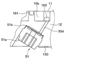
- a tip seal 161 for securing the airtightness of the compression chamber 15 is attached to the tip of the fixed tooth portion 122. Also, a tip seal 163 is attached to the tip of the movable tooth portion 112. The tip seal 161 extends along the spiral direction of the fixed tooth portion 122, and as shown in FIG. 5, its cross section is formed in a rectangular shape.
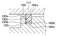
- the tip seal 161 is fitted in a recess 122 b (described in detail later) formed on the upper surface (the surface on the movable substrate portion 111 side) of the fixed tooth portion 122. Further, the tip seal 163 is fitted in a recess formed on the lower surface (the surface on the fixed substrate portion 121 side) of the movable tooth portion 112. Further, a tip seal 162 for securing the airtightness of the compression chamber 15 is attached to the tip end portion 120 a of the partition wall 120.
- the tip seal 162 corresponds to a first tip seal
- the tip seal 161 corresponds to a second tip seal.
- Both chip seals 161 and 162 are formed of a resin material such as polyether ether ketone resin (PEEK).
- PEEK polyether ether ketone resin
- a minute clearance is provided between the fixed tooth portion 122 formed on the fixed scroll 12 and the movable substrate portion 111 of the movable scroll 11.
- the tip seal 161 suppresses the leakage of the refrigerant through the clearance between the fixed tooth portion 122 formed on the fixed scroll 12 and the movable substrate portion 111 of the movable scroll 11.
- the tip seal 161 is disposed at the tip end 122 a of the fixed tooth 122. As shown in FIG. 5, the tip end portion 122 a of the fixed tooth portion 122 is formed with a concave portion 122 b for inserting the tip seal 161.
- the recess 122 b is a seal receiving groove.
- the tip seal 161 is fitted in a recess 122 b formed in the tip end 122 a of the fixed tooth 122.
- the tip seal 161 has a rectangular cross-sectional shape, and as shown in FIG. 5, the seal outer wall surface 161a facing the movable substrate portion 111 and the seal bottom outer wall surface 161b facing the accommodation groove bottom inner wall surface 122c. Have. The tip seal 161 protrudes from the tip end 122 a of the fixed tooth 122.
- the tip seal 162 passes the clearance between the partition wall 120 formed on the fixed base plate portion 121 of the fixed scroll 12 and the movable base plate portion 111 of the movable scroll 11 to lower the compression from the high stage compression chamber 15 a side. It is suppressed that the refrigerant leaks to the chamber 15b side.
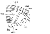
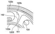
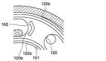
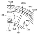
- the tip seal 162 is disposed at the tip end 120 a of the partition wall 120. As shown in FIG. 6, a recess 120 b for inserting the tip seal 162 is formed at the tip end 120 a of the partition wall 120. The tip seal 162 is fitted in a recess 120 b formed in the tip end 120 a of the partition wall 120.
- the tip seal 162 is disposed between the tip seal 161 located radially inward of the fixed substrate portion 121 from the partition wall 120 and the tip seal 161 located radially outward of the fixed substrate portion 121 from the partition wall 120 There is.
- the chip seal 162 is disposed with a gap provided between the chip seal 162 and the chip seal 161 located radially inward of the fixed substrate portion 121 with respect to the partition wall 120.
- a gap is provided between the tip seal 161 positioned radially outward and the tip seal 161.
- the tip seal 162 has a rectangular cross-sectional shape, and as shown in FIG. 6, a seal outer wall surface 162a facing the movable substrate portion 111 and a seal bottom outer wall surface 162b facing the accommodation groove bottom inner wall surface 120c. Have. The tip seal 162 projects beyond the tip end 120 a of the partition wall 120. Further, the width of the tip seal 162 is the same as the width of the tip seal 161.
- the partition part 1205 which separates between the recessed part 120b and the recessed part 122b is provided.
- the partition 1205 is formed between the recess 120 b and the recess 122 b located radially outward of the recess 120 b with respect to the fixed substrate 121, the recess 120 b, and radially inward of the fixed substrate 121 from the recess 120 b.
- This partition wall 1205 leaks the pressurized gas from the high stage side to the low stage side via the concave portion 122b and the concave portion 120b, and the refrigerant leaks from the high stage side compression chamber 15a side to the low stage side compression chamber 15b side. Be suppressed.
- the tip seals 161 and 162 do not protrude, and a space is provided between the tip seal bottom outer wall surfaces 161b and 162b and the receiving groove bottom inner wall surfaces 122c and 120c, and compression is performed from the end portions of the tip seals 161 and 162.
- the high-pressure refrigerant compressed in the chambers 15 b and 15 a may be introduced, and the chip seals 161 and 162 may be pressed to the movable substrate portion 111 by the refrigerant.
- the air is drawn into the compression chamber 15 from the suction port 30 a of the compressor 1.
- the crescent-shaped compression portion formed between the movable tooth portions 112 a and 112 b and the fixed tooth portion 122 moves from the outer peripheral side to the central side while reducing the volume.
- the refrigerant supplied to the compression chamber 15 is compressed as the volume of the compression chamber 15 decreases.
- the refrigerant compressed in the compression chamber 15 is discharged to the outside from the high pressure refrigerant discharge port 30 c of the compressor 1 through the discharge holes 123 of the fixed scroll 12 and the discharge chamber 124.
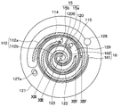
- FIG. 7 is a view showing the state of the fixed tooth portion 122 and the movable base portion 111 with respect to the turning angle of the movable scroll 11.
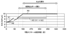
- FIG. 8 is a diagram showing the relationship between the rotation angle of the movable scroll shown in FIG. 7 and the pressure of each part in the compression chamber 15. As shown in FIG.
- the turning angle of the movable scroll 11 is 0 degree (360 degrees) ⁇ 45 degrees (405 degrees) ⁇ 75 degrees (435 degrees) ⁇ 90 degrees (450 degrees) ⁇ 180 degrees (540 degrees) ⁇
- the portions formed between the movable tooth portions 112 a and 112 b and the fixed tooth portion 122 according to the change of the turning angle of the movable scroll 11 Volume also changes.
- the pressures X1, X2, X3, and X4 of the respective portions formed between the movable tooth portions 112a and 112b and the fixed tooth portion 122 change as shown in FIG.
- the refrigerant suction port 128 is always open regardless of the turning angle of the movable scroll 11. Further, as shown in FIG. 8, the lower discharge port 114 is opened when the orbiting angle of the movable scroll 11 is in the range of about 130 to 450 degrees, and the refrigerant of a constant pressure X3 is discharged from the lower discharge port 114. Be done. Further, the discharge hole 123 is opened when the swing angle of the movable scroll 11 is about 180 degrees to 540 degrees, and the refrigerant with a constant pressure X4 is discharged from the discharge hole 123.
- a partition wall 120 is formed between the high-stage compression chamber 15 a and the low-stage compression chamber 15 b which are configured by the spiral groove 129 formed by the fixed teeth 122.
- a tip seal 162 for sealing a gap between the partition wall 120 and the movable substrate portion 111 is provided at the tip of the partition wall 120. Therefore, the tip seal 162 suppresses the leakage of fluid from the high-stage compression chamber 15a to the low-stage compression chamber 15b.
- the tip seal 162 and the tip seal 161 by integral molding.
- the chip seal 162 and the chip seal 161 are integrally formed by injection molding, the material is cooled at the connection portion between the chip seal 162 and the chip seal 161, and the chip seal 162 and the chip seal 161 may not be connected well. There is sex.
- the tip seal 162 and the tip seal 161 are separated, and a gap is provided between the tip seal 162 and the tip seal 161. Therefore, the tip seal 162 and the tip seal 161 can be formed well, and the formability is excellent.
- the fixed scroll 12 having the spiral fixed teeth 122 erected from the disk-shaped fixed substrate 121 and the one surface of the disk-shaped movable substrate 111 And a movable scroll 11 having a spiral movable tooth portion 112 which is erected and engaged with the fixed tooth portion 122, and by rotating the movable scroll 11 with respect to the fixed scroll 12, the fluid is compressed in multiple stages and discharged Do.
- a partition wall 120 is provided.
- a chip seal 162 is disposed in the recess 120 b formed in the tip end portion 120 a of the partition wall 120 and seals a gap between the partition wall 120 and the movable substrate portion 111.
- a tip seal is disposed in a recessed portion 122 b formed in the tip end portion 122 a of the fixed tooth portion 122 along the spiral fixed tooth portion 122, and seals the gap between the fixed tooth portion 122 and the movable substrate portion 111. It has 161. And between the recessed part 120b and the recessed part 122b, the partition part 1205 which separates between the recessed part 120b and the recessed part 122b is provided.
- the partition 1205 is provided between the recess 120b and the recess 122b to separate the recess 120b from the recess 122b, the high step side from the recess 122b to the recess 120b is provided. Since the leakage of fluid from the compression chamber to the lower stage compression chamber is suppressed, both the downsizing of the compressor and the improvement in efficiency can be achieved.
- a recessed portion 122b into which the tip seal 162 is inserted is formed at the tip end portion 120a of the partition wall 120, and the tip seal 162 is inserted into the recessed portion 122b. Therefore, the tip seal 162 can be easily attached to the recess 122 b.
- a tip seal 161 is provided at the tip end 122a of the fixed tooth 122 so as to follow the spiral fixed tooth 122, and seals a gap between the fixed tooth 122 and the movable substrate 111.
- the gap between the fixed tooth portion 122 and the movable substrate portion 111 is sealed by the tip seal 162, and the refrigerant leaking from the gap between the fixed tooth portion 122 and the movable substrate portion 111 can be suppressed.
- the width of the tip seal 162 is the same as the width of the tip seal 161. Therefore, the groove for accommodating the chip seal 162 and the groove for accommodating the chip seal 161 can be processed with the same cutting tool, and the work is different compared to the case where the widths of the chip seal 162 and the chip seal 161 are made different. It is possible to improve the quality and to reduce the manufacturing cost.
- the tip seal 162 protrudes from the tip end portion 120 a of the partition wall 120.
- the tip seal 162 can be disposed so as to protrude from the tip end 120 a of the partition wall 120.
- the tip seal 162 has the same width as the tip seal 161.
- the width of the tip seal 162 in the present embodiment is different from that of the tip seal 161.
- the partition wall 120 has a low-stage side surface 1201 in contact with the low-stage compression chamber and a high-stage side surface 1202 in contact with the high-stage compression chamber.
- the chip seal 162 is a chip seal 161 located radially inward of the fixed substrate 121 from the chip seal 162, and a chip seal 161 located lower in the radial direction of the fixed substrate 121 than the chip seal 162.
- a shape is formed along each of the high step side surfaces 1202.
- the tip seal 162 is configured separately from the tip seal 161.
- the tip seal 162 has a gap formed between the tip seal 162 and the tip seal 161 located radially outward of the fixed substrate portion 121 and is located radially inward of the fixed substrate portion 121 from the tip seal 162.
- a gap is formed between the tip seal 161 and the tip seal 161.
- the tip seal 161 is disposed in the recess 120b, and the tip seal 162 is disposed in the recess 122b.
- the partition part 1205 which separates between the recessed part 120b and the recessed part 122b is provided. Specifically, the partition 1205 is located between the recess 120 b and the recess 122 b located radially outward of the recess 120 b relative to the recess 120 b and between the recess 120 b and the recess 120 b in the radial direction of the fixed substrate 121. It is provided between the recessed part 122b located.
- the recess 120 b has a shape along the recess 122 b located inward of the recess 120 b in the radial direction of the fixed substrate 121 and the recess 122 b located outside of the recess 120 b in the radial direction of the fixed substrate 121.
- the recess 120 b has a shape along the side wall on the lower stage compression chamber side of the partition wall 120.
- the tip seal 162 and the tip seal 161 are configured separately, and a gap is provided between the tip seal 162 and the tip seal 161. Therefore, the tip seal 162 and the tip seal 161 can be formed well, and the formability is excellent.
- the tip seal 161 and the tip seal 162 are not branched, they can be stably molded. Therefore, the yield can be improved, and the chip seals 161 and 162 can be molded at low cost.
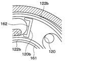
- a compressor 1 according to a third embodiment of the present disclosure will be described with reference to FIGS.
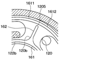
- the chip seal 162 of the present embodiment is connected to the chip seal 161 located radially outside the fixed substrate portion 121 with respect to the partition wall 120, and the chip seal located radially inward of the fixed substrate portion 121 with respect to the partition wall 120. A gap is formed between it and 161.
- the tip seal 162 is disposed in the recess 120 b formed in the tip end portion 120 a of the partition wall 120, and seals the gap between the partition wall 120 and the movable substrate portion 111.
- the tip seal 161 is disposed in a recess 122 b formed at the tip end 122 a of the fixed tooth 122 along the spiral fixed tooth 122, and seals the gap between the fixed tooth 122 and the movable substrate 111.
- the partition portion 1205 is provided between the recess 120 b and the recess 122 b.
- the partition portion 1205 is provided between the recess 120 b and the recess 122 b positioned on the inner side in the radial direction of the fixed substrate portion 121 than the recess 120 b.
- the recess 120 b is in communication with the recess 122 b located radially outward of the fixed substrate portion 121 with respect to the recess 120 b.
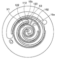
- FIG. 11 is an enlarged view of the lower stage compression chamber 15b partitioned by the partition wall 120 when the rotation angle of the movable scroll shown in FIG. 7 is 45 degrees (405 degrees).
- the pressure increases as the compression chamber 15 approaches the center of the fixed substrate portion 121. That is, in the lower stage compression chamber 15b, the pressure X1 outside the movable tooth portion 112b is lower than the pressure X3 inside the movable tooth portion 112b. That is, in the low-stage compression chamber 15b, the pressure difference between the pressure X1 outside the movable tooth portion 112b and the high-stage compression chamber 15a is the pressure X3 inside the movable tooth portion 112b and the high-stage side It becomes larger than the pressure difference with the compression chamber 15a.
- the direction in which the concave portion 120b and the concave portion 122b located radially outside the fixed substrate portion 121 from the concave portion 120b are connected is the concave portion 120b and the concave portion 122b positioned radially inward of the fixed substrate portion 121 from the concave portion 120b.
- the effect of suppressing the leakage of the refrigerant can be greater than when connecting the
- connection between the tip seal 162 and the tip seal 161 located radially outward of the fixed substrate portion 121 with respect to the tip seal 162 is the tip seal 162 and the fixed substrate portion 121 with the tip seal 162.
- the effect of suppressing the leakage of the refrigerant can be made greater than that of connecting the connection portion with the tip seal 161 located radially inward.
- the tip seal 162 of the present embodiment is connected to the tip seal 161 located radially outside the fixed substrate portion 121 with respect to the partition wall 120, the effect of suppressing refrigerant leakage can be improved.
- a gap is formed between the tip seal 162 and the tip seal 161 located radially inward of the fixed substrate portion 121 with respect to the partition wall 120. Therefore, when the chip seal 162 is connected to both the chip seal 161 located radially outside of the fixed substrate portion 121 from the partition wall 120 and the chip seal 161 located radially inward of the fixed substrate portion 121 from the partition wall 120 It is excellent in moldability compared with.
- the tip end portion 121a of the fixed tooth portion 122 is formed with a recess 122b into which the tip seal 161 is fitted, and the tip seal 161 is fitted into the recess 122b.
- the recess 122 b formed in the tip end portion 121 a of the fixed tooth portion 122 and the recess 122 b formed in the tip end portion 120 a of the partition wall 120 are continuous.
- gaps 161c and 162c are provided between the tip seal 161 and the recess 122b and between the tip seal 162 and the recess 122b, respectively.
- the chip seal 162 is connected to the chip seal 161 located radially inward of the fixed substrate portion 121 from the chip seal 162, and the chip seal 161 located radially outward of the fixed substrate portion 121 than the chip seal 162.
- a gap is formed between the
- the tip seal 162 is disposed in the recess 120 b formed in the tip end portion 120 a of the partition wall 120, and seals the gap between the partition wall 120 and the movable substrate portion 111.
- the tip seal 161 is disposed in a recess 122 b formed at the tip end 122 a of the fixed tooth 122 along the spiral fixed tooth 122, and seals the gap between the fixed tooth 122 and the movable substrate 111.
- the partition portion 1205 is provided between the recess 120 b and the recess 122 b.
- the partition 1205 is provided between the recess 120 b and the recess 122 b located radially outside the fixed substrate 121 with respect to the recess 120 b.
- the recess 120 b is in communication with the recess 122 b located radially outward of the fixed substrate portion 121 with respect to the recess 120 b.
- the refrigerant supplied to the compression chamber 15 is compressed as the volume of the compression chamber 15 decreases. At this time, the refrigerant enters the gap 161 c between the tip seal 161 and the recess 122 b from the end on the center side of the tip seal 161 where the refrigerant has a high pressure.
- the refrigerant that has entered the gap 161c between the tip seal 161 and the recess 122b flows toward the connection portion between the tip seal 161 and the tip seal 162, and then further connects the tip seal 161 and the tip seal 162. It flows into a gap 161c formed between the seal bottom outer wall surface 162b and the accommodation groove bottom inner wall surface 120c ahead of the portion and a gap 162c between the tip seal 162 and the recess 122b.
- the pressure of the refrigerant flowing through the gap 161 c between the tip seal 161 and the concave portion 122 b exerts a force to press the tip seal 161 against the movable substrate portion 111 side.
- the pressure of the refrigerant flowing through the gap 162c between the tip seal 162 and the concave portion 122b exerts a force to press the tip seal 162 against the movable substrate portion 111 side.
- the sealing performance can be further improved.
- a connecting portion is provided between the tip seal 162 and the tip seal 161 located radially outside the fixed substrate portion 121 with respect to the partition wall 120, and the tip seal 162 and the radial direction of the fixed substrate portion 121 with the partition wall 120.
- a gap can also be provided between the tip seal 161 located inside.
- connection portion between the chip seal 161 and the chip seal 162 is formed at a position relatively away from the center of the fixed substrate 121, the chip seal 162 is pressed to the movable substrate 111 side. And the sealing performance is reduced.
- a connection portion is provided between the chip seal 162 and the chip seal 161 located radially inward of the fixed substrate portion 121 with respect to the partition wall 120. It is possible to make the force pressed to the part 111 side stronger, and to secure higher sealing performance.
- a gap is formed between the tip seal 162 and the tip seal 161 located radially outside the fixed substrate portion 121 with respect to the partition wall 120. Therefore, when the chip seal 162 is connected to both the chip seal 161 located radially outside of the fixed substrate portion 121 from the partition wall 120 and the chip seal 161 located radially inward of the fixed substrate portion 121 from the partition wall 120 It is excellent in moldability compared with.
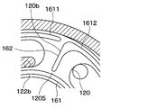
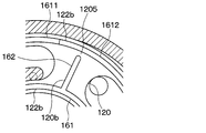
- the tip seal 161 is divided into two at the fixed tooth portion 122 positioned on the radially outer side of the fixed substrate portion 121 of the distal end portion 120 a of the partition wall 120.
- the tip seal 162 includes a first split tip seal 1621 connected to one split end of the tip seal 161, and a second split tip seal 1622 connected to the other split end of the tip seal. have.
- the tip seal 162 is divided into two by the fixed tooth portion 122 located on the radially outer side of the fixed base portion 121 of the tip end portion 120 a of the partition wall 120.
- the recess 120 b is connected to the first split recess 120 ba connected to one split end of the recess 122 b in which the chip seal 161 is disposed, and to the other split end of the recess 122 b in which the chip seal 161 is disposed. And the second divided recess 120bb.
- the partition wall portion 1205 is provided between the first divided concave portion 120ba and the concave portion 122b located radially inward of the fixed substrate portion 121 with respect to the first divided concave portion 120ba, the second divided concave portion 120bb, and the second divided concave portion 120bb. They are respectively provided between the fixed substrate portion 121 and the concave portion 122 b located on the inner side in the radial direction.
- the first split tip seal 1621 and the tip seal 1611 are disposed to surround the low-stage compression chamber 15b, and the second split tip seal 1622 and the tip seal 1612 are disposed to surround the high-stage compression chamber 15a. There is.
- the first split tip seal 1621 connected to one split end of the tip seal 161 and the second split tip seal 1622 connected to the other split end of the tip seal 161. It is possible to suppress the refrigerant leakage from the high-stage compression chamber 15a to the low-stage compression chamber 15b.
- first divided tip seal 1621 and the tip seal 1611 can be formed continuously, and furthermore, the second divided tip seal 1622 and the tip seal 1622 can be formed continuously and without a branch. Because it is excellent in formability.
- the tip seal 161 is divided into two at the fixed tooth portion 122 positioned on the radially outer side of the fixed substrate portion 121 of the distal end portion 120 a of the partition wall 120. Further, the tip seal 162 includes a first split tip seal 1621 connected to one split end of the tip seal 161, and a second split tip seal 1622 connected to the other split end of the tip seal. have.
- the tip seal 161 is divided into two at the fixed tooth portion 122 positioned on the radially outer side of the fixed substrate portion 121 of the distal end portion 120 a of the partition wall 120. Further, the tip seal 162 is connected to one divided end of the tip seal 161. Specifically, the tip seal 162 is connected to the tip seal 161 located radially outside the fixed substrate portion 121 with respect to the tip seal 162.
- the tip seal 162 is divided into two by the fixed tooth portion 122 located on the radially outer side of the fixed base portion 121 of the tip end portion 120 a of the partition wall 120.
- the recess 120 b is connected to one divided end of the recess in which the tip seal 162 is disposed.
- the partition portion 1205 is provided between the recess 120 b and the recess 122 b located on the inner side in the radial direction of the fixed substrate portion 121 than the recess 120 b.
- the width of the recess 120b is the same as that of the recess 122b in which the tip seal 162 is disposed.
- the tip seal 161 is divided into two by the fixed tooth portion 122 located on the radially outer side of the fixed substrate portion 121 of the tip end portion 120 a of the partition wall 120, and the tip seal 162 is one of the tip seals 161. It can also be configured to be connected to the split end.
- the tip seal 161 is divided into two at the fixed tooth portion 122 positioned on the radially outer side of the fixed substrate portion 121 of the distal end portion 120 a of the partition wall 120. Further, the tip seal 162 is connected to one divided end of the tip seal 161.
- the recess 120 b is connected to the recess 122 b in which one divided end of the tip seal 161 connected to the tip seal 162 is disposed.
- the partition portion 1205 is provided between the recess 120 b and the recess 122 b located more inward in the radial direction of the fixed substrate portion 121 than the recess 120 b.
- the width of the recess 120b is the same as that of the recess 122b in which the tip seal 162 is disposed.
- the recess 120 b has a shape along the side wall on the lower stage compression chamber side of the partition wall 120.
- the tip seal 161 is divided into two by the fixed tooth portion 122 located on the radially outer side of the fixed substrate portion 121 of the tip end portion 120 a of the partition wall 120, and the tip seal 162 is one of the tip seals 161.
- the width of the recess 120 b is half or more of the width of the recess 122 b. Also, the width of the recess 120 b gradually widens as it approaches the recess 122 b.
- the tip seal 162 is molded so as to conform to the shape of the recess 120 b formed in the distal end portion 120 a of the partition wall 120, and is disposed in the recess 120 b. Further, the tip seal 161 is disposed in the concave portion 122 b formed in the tip end portion 122 a of the fixed tooth portion 122 so as to be along the spiral fixed tooth portion 122.
- the tip seal 162 disposed in the recess 120 b is applied with a pressure of about 0.5 times or more that of the tip seal 161 disposed in the recess 122 b, the tip seal 162 needs to have a width of half or more of the tip seal 161. is there. Therefore, fluid leakage can be suppressed by setting the width of the recess 120 b to be equal to or more than half the width of the recess 122 b.
- the dead volume on the partition wall 120 can be reduced by widening the width of the tip seal 162, it is desirable that the width of the tip seal 162 be wider than the width of the tip seal 161.
- the partition 1205 is provided between the recess 120 b and the recess 122 b located radially outside the fixed substrate 121 with respect to the recess 120 b.
- the recess 120 b is in communication with the recess 122 b located on the inner side in the radial direction of the fixed substrate portion 121 than the recess 120 b.
- each tip seal 161, 162 fitted into the recess 120b and the recess 122b can be facilitated, so that low cost can be realized. .
- the partition wall portion 1205 is provided between the concave portion 120 b and the concave portion 122 b located radially outside the fixed substrate portion 121 with respect to the concave portion 120 b.
- the recess 120 b is in communication with the recess 122 b located on the inner side in the radial direction of the fixed substrate portion 121 than the recess 120 b.
- the partition wall 1205 is provided between the recess 120 b and the recess 122 b located radially inward of the fixed substrate 121 from the recess 120 b.
- the recess 120 b is in communication with the recess 122 b located radially outward of the fixed substrate portion 121 with respect to the recess 120 b.
- the width of the recess 120 b gradually widens as it approaches the recess 122 b.
- the chip seals 161 and 162 to be inserted can be easily molded, so that the cost for forming can be reduced. It is possible to reduce.
- FIG. 1 A compressor according to an eleventh embodiment of the present disclosure will be described using FIG.
- the recess 120b is connected to one split end of the recess in which the tip seal 162 is disposed.
- the partition 1205 is provided between the recess 120 b and the recess 122 b located on the inner side in the radial direction of the fixed substrate 121 with respect to the recess 120 b.
- FIG. 1 A compressor according to a twelfth embodiment of the present disclosure will be described using FIG.
- the compressor 1 of the present embodiment is different from the compressor of the eleventh embodiment in that the width of the recess 120 b is a half of the recess 122 b.
- the width of the recess 120 b has a portion which is a half of the recess 122 b, and the width of the recess 120 b gradually widens as it approaches the recess 122 b.
- the tip seal 162 is molded in accordance with the shape of the recess 120 b and disposed in the recess 120 b.
- the chip seals 161 and 162 to be inserted can be easily molded, so that the cost for forming can be reduced. It is possible to reduce.
- FIG. 1205 A compressor according to a thirteenth embodiment of the present disclosure will be described using FIG.
- a partition 1205 is provided between the recess 120 b and the recess 122 b located radially inward of the fixed substrate 121 from the recess 120 b as compared with the compressor of the second embodiment. It differs in that it is not.
- the partition 1205 is disposed between the recess 120b and the recess 122b located radially outside the fixed substrate 121 from the recess 120b, and the recess 120b and the inner side in the radial direction of the fixed substrate 121 from the recess 120b. It is also possible not to arrange the partition 1205 between it and the recess 122b located in the
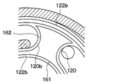
- a recessed portion 120 b is formed along a recessed portion 122 b located along the recessed portion 122 b located radially inward of the recessed portion 120 b and a radial direction of the fixed substrate portion 121 from the recessed portion 120 b. It has a portion 120bd formed along the concave portion 122b located outside, and a linear portion 120be connecting the portion 120bc and the portion 120bd.
- the tip seal 161 is molded in accordance with the shape of each of the portions 120 bc, 120 bd, and 120 be.
- the recess 120b can be formed, and the chip seal 161 molded in accordance with the shape of the recess 120b can be disposed in the recess 120b.
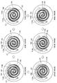
- the concave portion 120 b of the eighth embodiment has a curved shape along the side wall on the low pressure side compression chamber side of the partition wall 120.
- the recess 120b may be shaped along the side wall on the lower stage compression chamber side of the partition wall 120. Specifically, as shown in FIG. 25, the recess 120 b can be formed at a position separated by a predetermined length from the side wall on the low pressure side compression chamber side of the partition wall 120. Further, as shown in FIG.
- the concave portion 120b can be formed by combining two curves along the side wall on the low pressure side compression chamber side of the partition wall 120. Further, as shown in FIG. 27, the concave portion 120b can be formed by combining three curves along the side wall on the low pressure side compression chamber side of the partition wall 120.
- the tip seal 162 is disposed in each recess 120 b.
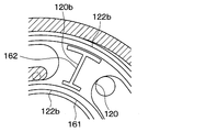
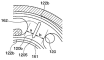
- FIG. 1 the distance a between the side wall on the low stage side compression chamber side of the recess 120 b and the side wall on the low stage side compression chamber side of the partition wall 120 and the high stage side compression chamber side of the recess 120 b
- the distance b between the side wall of and the side wall on the high stage side compression chamber side of the partition wall 120 is not defined.
- the shortest distance a between the side wall on the low-stage compression chamber side of the recess 120b and the side wall on the low-stage compression chamber side of the partition wall 120 is the side wall on the high-stage compression chamber side of the recess 120b. It is formed to be smaller than the shortest distance b between the and the side wall on the high stage side compression chamber side of the partition wall. Then, the tip seal 162 is disposed in the recess 120 b.
- the dead space between the tip portion 120 a of the partition wall 120 and the movable substrate portion 111 can be reduced, and the efficiency of the compressor 1 can be improved.
- the tip seal 161 is divided in the middle. Specifically, the tip seal 161 divided in the middle is disposed in the continuous concave portion 120b.
- the tip seal 161 is divided in the middle. Specifically, the chip seal 161 is disposed in each of the recessed portions 120 b divided in the middle.
- the chip seal 161 can also be disposed in each of the recessed portions 120 b divided in the middle.
- the compressor 1 of the present embodiment is the fixed base plate portion 121, and an intermediate pressure suction hole communicating with the low pressure side compression chamber 15b with the intermediate pressure suction port 30b of the compressor 1. 116 are formed.
- the intermediate pressure suction hole 116 communicating with the intermediate pressure suction port 30 b of the compressor 1 can be formed in the substrate portion 121.
- FIGS. A compressor according to a twentieth embodiment of the present disclosure will be described using FIGS.
- the heat pump cycle 100 to which the compressor 1 of the present embodiment is applied is further between the gas-liquid separator 4 and the second expansion valve 5 in comparison with the heat pump cycle 100 to which the compressor 1 of the first embodiment is applied.
- the second embodiment differs in that the third expansion valve 7 and the gas-liquid separator 8 are provided.
- the third expansion valve 7 is a low-stage pressure reducing section that reduces the pressure of the intermediate pressure liquid phase refrigerant flowing out from the liquid phase refrigerant outlet of the gas liquid separator 4 to a low pressure refrigerant. The same as the expansion valve 3.
- the gas-liquid separator 8 is a gas-liquid separation unit that separates the gas-liquid of the intermediate pressure refrigerant decompressed by the third expansion valve 7.
- the intermediate pressure gas phase refrigerant separated by the gas-liquid separator 8 is injected into the refrigerant in the middle of the compression process in the compression chamber 15 of the compressor 1 via the intermediate pressure suction port 30 d of the compressor 1.
- the second expansion valve 5 is a low-stage pressure reducing section for reducing the pressure of the intermediate pressure liquid phase refrigerant flowing out from the liquid phase refrigerant outlet of the gas liquid separator 8 to a low pressure refrigerant, and its basic configuration is the first The same as the expansion valve 3.
- the present compressor 1 can also be applied to such a heat pump cycle 100.
- a low stage injection channel 941 and a low stage injection chamber 942 are further formed in the fixed substrate portion 121 of the present embodiment. Further, the low-stage injection chamber 942 is provided with a check valve 51 for preventing the refrigerant flowing into the low-stage compression chamber 15b from flowing back to the intermediate pressure suction port 30d.
- the lower stage injection channel 941 is a channel through which the refrigerant injected into the lower stage compression chamber 15b passes.
- a pipe is press-fit into the low-stage injection flow path 941, the illustration of the pipe is omitted in FIG. 33 and the like.
- the said pipe has a flange part, and a compressor is sealed by connecting with the cylindrical member 31 of a housing.
- the refrigerant that has passed through the low stage injection flow channel 941 flows into the low stage injection chamber 942.
- the low stage injection chamber 942 is a space formed astride the discharge plate 140 and the fixed scroll 12 as a space into which the refrigerant having passed through the low stage injection flow passage 941 flows.
- the refrigerant flowing into the lower stage injection chamber 942 is injected into the lower stage compression chamber 15 b through the lower stage injection port 943 which is a through hole.
- the intermediate injection passage 951 is a passage through which the refrigerant injected into the intermediate pressure chamber 981 passes.
- a pipe is press-fit into the intermediate injection flow channel 951, the illustration of the pipe is omitted in FIG.
- the pipe has a flange and is connected to the cylindrical member 31 of the compressor housing 30 by the flange to seal the compressor.
- the refrigerant having passed through the intermediate injection passage 951 is injected into the intermediate pressure chamber 981.
- the check valve 51 has a valve seat 51a and a reed valve 51b.
- the reed valve 51b blocks the passage communicating with the intermediate pressure suction port 30d and the refrigerant flowing into the low pressure side compression chamber 15b It prevents the backflow to the intermediate pressure suction port 30d side.
- the present compressor 1 can also be applied to such a heat pump cycle 100.
- the low-stage discharge port 114 and the high-stage suction port 115 shown in FIG. 3 may be directly connected.
- the recessed portion 122b is formed in the tip end portion 122a of the fixed tooth portion 122, and the tip seal 161 is fitted in the recessed portion 122b, and the recessed portion 120b is formed in the tip end portion 120a of the partition wall 120
- the tip seal 162 is inserted into the recess 120b, the present invention is not limited to such an attachment method.
- the chip seal is inserted into the recess provided with the recess in the partition wall 120 of the fixed substrate portion 121, but it is the movable substrate portion 111 and contacts the partition wall 120 of the fixed substrate portion 121.
- the portion may be provided with a tip seal that fits into the recess and the recess.
- the tip seal is disposed at the tip of the movable tooth 112.
- the tip seal need not necessarily be disposed at the tip of the movable tooth 112.
- the low-stage compression chamber 15b is disposed outside the spiral groove 129 formed by the fixed teeth 122, and the high-stage compression chamber 15a is disposed inside the spiral groove 129.
- the low-stage compression chamber 15b is disposed inside the spiral groove 129 formed by the fixed teeth 122, and the high-stage compression chamber 15a is disposed outside the spiral groove 129. It is also good.
- tip seal 162 contains what was constituted so that the section shape of tip seal 162 might be a rectangle, it can also be considered as shapes other than a rectangle.
- the low stage compressor forming the low stage compression chamber 15b and the high stage compression forming the high stage compression chamber 15a may be separately configured.
- the number of turns of the fixed tooth portion 122 formed on the fixed scroll 12 is greater than 1.5 turns, but the number of turns of the fixed tooth portion 122 formed on the fixed scroll 12 is The number may be less than 1.5 turns.
- the gap between the seal tip seal 162 and the movable substrate portion 111 and the gap between the tip seal 161 and the movable substrate portion 111 Fluid can leak from the higher stage compression chamber through the lower stage compression chamber to the lower stage suction chamber.
- the recess 120b and the recess 122b are separated between the recess 120b and the recess 122b.
- the partition 1205 it is possible to suppress the fluid from leaking from the high-stage compression chamber 15a to the low-stage suction chamber through the low-stage compression chamber 15b.
- this indication is not limited to above-mentioned embodiment, and can be changed suitably. Moreover, said each embodiment is not mutually irrelevant and can be combined suitably, unless the combination is clearly impossible. Further, in each of the above-described embodiments, it is needless to say that the elements constituting the embodiment are not necessarily essential except when clearly indicated as being essential and when it is considered to be obviously essential in principle. Yes. Further, in the above embodiments, when numerical values such as the number, numerical value, amount, range, etc. of constituent elements of the embodiment are mentioned, it is clearly indicated that they are particularly essential and clearly limited to a specific number in principle. It is not limited to the specific number except when it is done. Further, in the above embodiments, when referring to materials, shapes, positional relationships, etc. of constituent elements etc., unless specifically stated otherwise or in principle when limited to a specific material, shape, positional relationship, etc., etc. It is not limited to the material, the shape, the positional relationship, etc.
- the compressor includes a fixed scroll having a spiral fixed toothed portion erected from a disk-shaped fixed base plate, and a circle And a movable scroll having a spiral movable tooth portion which is erected from one surface of the plate-like movable base plate portion and which meshes with the fixed tooth portion. Then, the movable scroll is turned with respect to the fixed scroll, thereby compressing the fluid in multiple stages and discharging it.
- a partition wall which is erected from the fixed substrate portion toward the movable substrate portion and which divides the appropriate position of the spiral groove formed by the fixed tooth portion into a high-stage compression chamber and a low-stage compression chamber 120). Further, it has a first seal member (162) which is disposed in the concave portion 120b (120b) formed at the front end portion of the partition wall and seals the gap between the partition wall and the movable substrate portion. In addition, it is disposed in the concave portion 122b (122b) formed in the tip end portion (122a) of the fixed tooth portion so as to follow the spiral fixed tooth portion, and seals the gap between the fixed tooth portion and the movable substrate portion 2 has a sealing member (161). A partition (1205) is provided between the recess 120b and the recess 122b to separate the recess 120b from the recess 122b.
- the partition wall portion is provided between the recess 120b and the recess 122b located radially inward of the recess 120b from the recess 120b, and the recess 120b is formed from the recess 120b. It is in communication with the recess 122b located radially outward of the
- the recess 120b communicates with the recess 122b located radially outward of the fixed substrate portion from the recess 120b, the recess 120b is located radially inward of the fixed substrate portion relative to the recess 120b. Since a large amount of high-pressure refrigerant introduced into the gap between the second seal member and the recess 122b can be introduced to the back surface of the first seal member as compared to the case where no communication occurs, the second seal member and the movable substrate portion Thus, the efficiency of the compressor can be improved.
- connection between the recess 120b and the recess 122b located radially outside the fixed substrate from the recess 120b is the connection between the recess 120b and the recess 122b located radially inside the fixed substrate from the recess 120b.
- the differential pressure applied to the first seal member is larger than that.
- the amount of high-pressure refrigerant introduced to the back surface of the first seal member can be reduced as compared with the case where the recess 120b communicates with the recess 122b located radially inward of the recess 120b from the recess 120b. For this reason, pressure sufficient to press the first and second seal members against the movable substrate portion can be generated on the back surfaces of the first and second seal members, and the compressor efficiency can be improved.
- the partition wall portion is provided between the recess 120b and the recess 122b located radially outward of the recess 120b relative to the fixed substrate portion, and the recess 120b is fixed to the fixed substrate portion from the recess 120b. It communicates with the recess 122b located radially inward of the
- the recess 120b communicates with the recess 122b located radially inward of the fixed substrate portion than the recess 120b, the recess 120b is located between the recess 120b and the recess 122b located radially inward of the fixed substrate. Since a large amount of high-pressure fluid introduced into the gap between the second seal member and the recess 122b can be introduced to the back surface of the first seal member as compared with the case where they do not communicate, the second seal member and the movable substrate portion Thus, the efficiency of the compressor can be improved.
- the recess 120b communicates with the recess 122b located radially inward of the fixed substrate than the recess 120b, the recess 120b communicates with the recess 122b located radially inward of the fixed substrate from the recess 120b. Since the high pressure fluid introduced to the back surface of the first seal member can be increased as compared with the case where it is not used, the sealability can be further improved.
- the concave portion 122 b is divided into two at the fixed tooth portion positioned on the radially outer side of the fixed substrate portion at the tip end portion of the partition wall.
- the recess 120b includes a first split recess (120ba) connected to one split end of the recess 122b and a second split recess (120bb) connected to the other split end of the recess 122b.
- the partition wall portion is formed between the first divided concave portion and the concave portion 122b located radially outward of the first divided concave portion with respect to the fixed substrate portion, the second divided concave portion, and the second divided concave portion in the radial direction of the fixed substrate portion. It is provided between the recessed part 122b located in the outer side.
- the recess 122 b and the recess 120 b can be processed by one-stroke writing, the recess 122 b and the recess 120 b can be stably processed, and cost reduction can be realized. Further, since the contact between the first seal member and the second seal member and the recess 120 b and the recess 122 b is also stable, fluid leakage can be reduced more effectively. Therefore, the compression efficiency of the compressor can be improved.
- the seal member fitted into the second seal member and the first divided recess can be continuously molded, and the seal member fitted into the second seal member and the second divided recess is continuously molded. Because it can be done, it is excellent in moldability.
- the recess 122b is divided into two by the fixed tooth portion positioned radially outside the fixed substrate portion at the tip end of the partition wall, and the recess 120b is one of the recess 122b.
- the dividing wall is provided between the first dividing recess and the other dividing end of the recess 122b.
- the concave portion 122b is divided into two by the fixed tooth portion positioned on the radially outer side of the fixed substrate portion at the tip end portion of the partition wall, and the concave portion 120b is connected to one divided end portion of the concave portion 122b.
- the partition wall portion may be configured to be provided between the first dividing recess and the other dividing end of the recess 122b.
- the width of the recess 120 b is half or more of the width of the recess 122 b.
- the first seal member disposed in the recess 120 b receives a pressure of 0.5 or more times the pressure applied to the second seal member disposed in the recess 122 b. Therefore, fluid leakage can be suppressed by setting the width of the recess 120 b to be equal to or more than half the width of the recess 122 b.
- the recess 120b is formed on at least one of the recess 122b located radially inward of the fixed substrate from the recess 120b and the recess 122b located radially outward of the fixed substrate from the recess 120b. It has a shape along with it.
- the length of the gap between the recess 120 b and the recess 122 b can be made longer compared to the case where the recess 120 b is configured not to be along the recess 122 b, the fluid leakage suppressing effect is improved. Can.
- the recess 120b has a shape along the side wall on the low stage side compression chamber side of the partition wall and the side wall on the high stage side compression chamber side of the partition wall.
- the dead space between the tip of the partition wall and the movable substrate portion can be reduced, and the efficiency of the compressor can be improved.
- the shortest distance (a) between the side wall on the lower stage compression chamber side of the recess 120b and the side wall on the lower stage compression chamber side of the partition wall is the height of the recess 120b. It is formed to be smaller than the shortest distance (b) between the side wall on the step side compression chamber side and the side wall on the high step side compression chamber side of the partition wall.
- the dead space between the tip of the partition wall and the movable substrate portion can be reduced, and the efficiency of the compressor can be improved.
- the first seal member disposed in the recess 120 b is connected to the second seal member disposed in the recess 122 b.
- the number of turns of the fixed tooth portion formed in the fixed scroll is less than 1.5 turns.
- the fluid flows through the gap between the first seal member and the movable substrate portion and the gap between the second seal member and the movable substrate portion Can leak from the higher stage compression chamber through the lower stage compression chamber to the lower stage suction chamber.
- the fluid contains carbon dioxide.
- the fluid pressure in the compressor is very high, which is particularly effective when compressing a fluid containing carbon dioxide.
Landscapes
- Engineering & Computer Science (AREA)
- Mechanical Engineering (AREA)
- General Engineering & Computer Science (AREA)
- Rotary Pumps (AREA)
- Applications Or Details Of Rotary Compressors (AREA)
Applications Claiming Priority (2)
| Application Number | Priority Date | Filing Date | Title |
|---|---|---|---|
| JP2017-214075 | 2017-11-06 | ||
| JP2017214075A JP6881245B2 (ja) | 2017-11-06 | 2017-11-06 | 圧縮機 |
Publications (1)
| Publication Number | Publication Date |
|---|---|
| WO2019088240A1 true WO2019088240A1 (ja) | 2019-05-09 |
Family
ID=66331890
Family Applications (1)
| Application Number | Title | Priority Date | Filing Date |
|---|---|---|---|
| PCT/JP2018/040771 Ceased WO2019088240A1 (ja) | 2017-11-06 | 2018-11-01 | 圧縮機 |
Country Status (2)
| Country | Link |
|---|---|
| JP (1) | JP6881245B2 (enExample) |
| WO (1) | WO2019088240A1 (enExample) |
Families Citing this family (1)
| Publication number | Priority date | Publication date | Assignee | Title |
|---|---|---|---|---|
| JP7329774B2 (ja) * | 2019-11-11 | 2023-08-21 | パナソニックIpマネジメント株式会社 | スクロール圧縮機 |
Citations (5)
| Publication number | Priority date | Publication date | Assignee | Title |
|---|---|---|---|---|
| JPH06288361A (ja) * | 1993-04-07 | 1994-10-11 | Hitachi Ltd | スクロール圧縮機 |
| JPH07139481A (ja) * | 1993-11-19 | 1995-05-30 | Tokico Ltd | スクロール式流体機械 |
| JP2003129970A (ja) * | 2001-10-22 | 2003-05-08 | Anest Iwata Corp | スクロール流体機械 |
| JP2009052462A (ja) * | 2007-08-27 | 2009-03-12 | Panasonic Corp | スクロール圧縮機 |
| JP2017053286A (ja) * | 2015-09-10 | 2017-03-16 | アネスト岩田株式会社 | スクロール流体機械 |
Family Cites Families (1)
| Publication number | Priority date | Publication date | Assignee | Title |
|---|---|---|---|---|
| JP2002130156A (ja) * | 2000-10-20 | 2002-05-09 | Anest Iwata Corp | 多段式流体圧縮部を備えたスクロール流体機械 |
-
2017
- 2017-11-06 JP JP2017214075A patent/JP6881245B2/ja active Active
-
2018
- 2018-11-01 WO PCT/JP2018/040771 patent/WO2019088240A1/ja not_active Ceased
Patent Citations (5)
| Publication number | Priority date | Publication date | Assignee | Title |
|---|---|---|---|---|
| JPH06288361A (ja) * | 1993-04-07 | 1994-10-11 | Hitachi Ltd | スクロール圧縮機 |
| JPH07139481A (ja) * | 1993-11-19 | 1995-05-30 | Tokico Ltd | スクロール式流体機械 |
| JP2003129970A (ja) * | 2001-10-22 | 2003-05-08 | Anest Iwata Corp | スクロール流体機械 |
| JP2009052462A (ja) * | 2007-08-27 | 2009-03-12 | Panasonic Corp | スクロール圧縮機 |
| JP2017053286A (ja) * | 2015-09-10 | 2017-03-16 | アネスト岩田株式会社 | スクロール流体機械 |
Also Published As
| Publication number | Publication date |
|---|---|
| JP2019085911A (ja) | 2019-06-06 |
| JP6881245B2 (ja) | 2021-06-02 |
Similar Documents
| Publication | Publication Date | Title |
|---|---|---|
| US9181945B2 (en) | Scroll compressor with channels intermittently communicating internal and external compression chambers with back pressure chamber | |
| JP5954453B1 (ja) | スクロール型圧縮機 | |
| US11022120B2 (en) | Scroll compressor with first and second compression chambers having first and second discharge start points | |
| CN102472272B (zh) | 涡盘包含具有不同高度的部分的涡旋压缩机 | |
| CN101166903A (zh) | 旋转式压缩机 | |
| EP2359006B1 (en) | Screw compressor | |
| US6659743B2 (en) | Scroll fluid machine having multistage compressing part | |
| JPWO2018131111A1 (ja) | 多段スクロール圧縮機 | |
| KR20180093693A (ko) | 스크롤 압축기 | |
| WO2019088240A1 (ja) | 圧縮機 | |
| KR20190000070A (ko) | 냉매 역류 방지 구조가 구비된 압축기 | |
| WO2005010372A1 (ja) | スクロール圧縮機 | |
| WO2016189801A1 (ja) | シリンダ回転型圧縮機 | |
| CN101778999B (zh) | 具有一体式轴承盖和排放增压室分隔件的螺杆压缩机 | |
| JP6130271B2 (ja) | スクロール圧縮機 | |
| JPWO2019043741A1 (ja) | 圧縮機 | |
| RU2448273C2 (ru) | Роторная винтовая машина | |
| KR101931627B1 (ko) | 실린더회전형 압축기 | |
| JP6285816B2 (ja) | 圧縮機 | |
| CN111868384B (zh) | 多级压缩机 | |
| JP7139718B2 (ja) | 圧縮機 | |
| JP6996267B2 (ja) | スクロール圧縮機 | |
| KR100882480B1 (ko) | 스크롤 압축기 | |
| JP2019085912A (ja) | 多段スクロール圧縮機 | |
| JP2021042750A (ja) | スクロール圧縮機 |
Legal Events
| Date | Code | Title | Description |
|---|---|---|---|
| 121 | Ep: the epo has been informed by wipo that ep was designated in this application |
Ref document number: 18873173 Country of ref document: EP Kind code of ref document: A1 |
|
| NENP | Non-entry into the national phase |
Ref country code: DE |
|
| 122 | Ep: pct application non-entry in european phase |
Ref document number: 18873173 Country of ref document: EP Kind code of ref document: A1 |