WO2019088233A1 - コネクタ、接続対象物及び電子機器 - Google Patents
コネクタ、接続対象物及び電子機器 Download PDFInfo
- Publication number
- WO2019088233A1 WO2019088233A1 PCT/JP2018/040748 JP2018040748W WO2019088233A1 WO 2019088233 A1 WO2019088233 A1 WO 2019088233A1 JP 2018040748 W JP2018040748 W JP 2018040748W WO 2019088233 A1 WO2019088233 A1 WO 2019088233A1
- Authority
- WO
- WIPO (PCT)
- Prior art keywords
- actuator
- connection object
- insulator
- connector
- open position
- Prior art date
- Legal status (The legal status is an assumption and is not a legal conclusion. Google has not performed a legal analysis and makes no representation as to the accuracy of the status listed.)
- Ceased
Links
Images

















Classifications
-
- H—ELECTRICITY
- H01—ELECTRIC ELEMENTS
- H01R—ELECTRICALLY-CONDUCTIVE CONNECTIONS; STRUCTURAL ASSOCIATIONS OF A PLURALITY OF MUTUALLY-INSULATED ELECTRICAL CONNECTING ELEMENTS; COUPLING DEVICES; CURRENT COLLECTORS
- H01R12/00—Structural associations of a plurality of mutually-insulated electrical connecting elements, specially adapted for printed circuits, e.g. printed circuit boards [PCB], flat or ribbon cables, or like generally planar structures, e.g. terminal strips, terminal blocks; Coupling devices specially adapted for printed circuits, flat or ribbon cables, or like generally planar structures; Terminals specially adapted for contact with, or insertion into, printed circuits, flat or ribbon cables, or like generally planar structures
- H01R12/70—Coupling devices
- H01R12/77—Coupling devices for flexible printed circuits, flat or ribbon cables or like structures
- H01R12/771—Details
- H01R12/774—Retainers
-
- H—ELECTRICITY
- H01—ELECTRIC ELEMENTS
- H01R—ELECTRICALLY-CONDUCTIVE CONNECTIONS; STRUCTURAL ASSOCIATIONS OF A PLURALITY OF MUTUALLY-INSULATED ELECTRICAL CONNECTING ELEMENTS; COUPLING DEVICES; CURRENT COLLECTORS
- H01R12/00—Structural associations of a plurality of mutually-insulated electrical connecting elements, specially adapted for printed circuits, e.g. printed circuit boards [PCB], flat or ribbon cables, or like generally planar structures, e.g. terminal strips, terminal blocks; Coupling devices specially adapted for printed circuits, flat or ribbon cables, or like generally planar structures; Terminals specially adapted for contact with, or insertion into, printed circuits, flat or ribbon cables, or like generally planar structures
- H01R12/70—Coupling devices
- H01R12/77—Coupling devices for flexible printed circuits, flat or ribbon cables or like structures
- H01R12/79—Coupling devices for flexible printed circuits, flat or ribbon cables or like structures connecting to rigid printed circuits or like structures
-
- H—ELECTRICITY
- H01—ELECTRIC ELEMENTS
- H01R—ELECTRICALLY-CONDUCTIVE CONNECTIONS; STRUCTURAL ASSOCIATIONS OF A PLURALITY OF MUTUALLY-INSULATED ELECTRICAL CONNECTING ELEMENTS; COUPLING DEVICES; CURRENT COLLECTORS
- H01R12/00—Structural associations of a plurality of mutually-insulated electrical connecting elements, specially adapted for printed circuits, e.g. printed circuit boards [PCB], flat or ribbon cables, or like generally planar structures, e.g. terminal strips, terminal blocks; Coupling devices specially adapted for printed circuits, flat or ribbon cables, or like generally planar structures; Terminals specially adapted for contact with, or insertion into, printed circuits, flat or ribbon cables, or like generally planar structures
- H01R12/70—Coupling devices
- H01R12/7005—Guiding, mounting, polarizing or locking means; Extractors
- H01R12/7011—Locking or fixing a connector to a PCB
-
- H—ELECTRICITY
- H01—ELECTRIC ELEMENTS
- H01R—ELECTRICALLY-CONDUCTIVE CONNECTIONS; STRUCTURAL ASSOCIATIONS OF A PLURALITY OF MUTUALLY-INSULATED ELECTRICAL CONNECTING ELEMENTS; COUPLING DEVICES; CURRENT COLLECTORS
- H01R12/00—Structural associations of a plurality of mutually-insulated electrical connecting elements, specially adapted for printed circuits, e.g. printed circuit boards [PCB], flat or ribbon cables, or like generally planar structures, e.g. terminal strips, terminal blocks; Coupling devices specially adapted for printed circuits, flat or ribbon cables, or like generally planar structures; Terminals specially adapted for contact with, or insertion into, printed circuits, flat or ribbon cables, or like generally planar structures
- H01R12/70—Coupling devices
- H01R12/82—Coupling devices connected with low or zero insertion force
- H01R12/85—Coupling devices connected with low or zero insertion force contact pressure producing means, contacts activated after insertion of printed circuits or like structures
- H01R12/88—Coupling devices connected with low or zero insertion force contact pressure producing means, contacts activated after insertion of printed circuits or like structures acting manually by rotating or pivoting connector housing parts
-
- H—ELECTRICITY
- H01—ELECTRIC ELEMENTS
- H01R—ELECTRICALLY-CONDUCTIVE CONNECTIONS; STRUCTURAL ASSOCIATIONS OF A PLURALITY OF MUTUALLY-INSULATED ELECTRICAL CONNECTING ELEMENTS; COUPLING DEVICES; CURRENT COLLECTORS
- H01R13/00—Details of coupling devices of the kinds covered by groups H01R12/70 or H01R24/00 - H01R33/00
- H01R13/62—Means for facilitating engagement or disengagement of coupling parts or for holding them in engagement
- H01R13/629—Additional means for facilitating engagement or disengagement of coupling parts, e.g. aligning or guiding means, levers, gas pressure electrical locking indicators, manufacturing tolerances
-
- H—ELECTRICITY
- H01—ELECTRIC ELEMENTS
- H01R—ELECTRICALLY-CONDUCTIVE CONNECTIONS; STRUCTURAL ASSOCIATIONS OF A PLURALITY OF MUTUALLY-INSULATED ELECTRICAL CONNECTING ELEMENTS; COUPLING DEVICES; CURRENT COLLECTORS
- H01R13/00—Details of coupling devices of the kinds covered by groups H01R12/70 or H01R24/00 - H01R33/00
- H01R13/62—Means for facilitating engagement or disengagement of coupling parts or for holding them in engagement
- H01R13/639—Additional means for holding or locking coupling parts together, after engagement, e.g. separate keylock, retainer strap
Definitions
- the present disclosure relates to a connector, an object to be connected, and an electronic device.
- a connector used for an electronic device or the like is required to have a structure capable of easily inserting and removing an object to be connected from the viewpoint of improvement in workability.
- a connector used for an electronic device or the like when all the steps are automatically performed by the machine without using the hand of the operator, or when manually inserting and removing the equipment at the time of maintenance of the equipment, The demand for
- the cable connector and the connection object are securely connected by a single operation of inserting the connection object.
- a connector according to an embodiment of the present disclosure is An insulator capable of inserting and removing a connection object; An actuator capable of pivoting between a closed position closing relative to the insulator and an open position opening relative to the insulator; Equipped with When the actuator moves from the closed position to the open position, the actuator rotates from the removal side to the insertion side of the connection object with respect to the insulator, and holds the open position by itself.
- FIG. 6 is a cross-sectional view taken along the line VI-VI in FIG. 5;
- FIG. 7 is a cross-sectional view taken along the line VII-VII in FIG. 5; It is sectional drawing which follows the VIII-VIII arrow line of FIG. FIG.
- FIG. 6 is a cross-sectional view taken along the line IX-IX in FIG. 5;
- FIG. 6 is a cross-sectional view taken along the line XX in FIG. 5;
- FIG. 6 is a cross-sectional view taken along the line XI-XI in FIG. 5; It is a front view of the connector of FIG. 1 when a connection target object is inserted.
- FIG. 13 is a cross-sectional view taken along line XIII-XIII of FIG. 12; It is sectional drawing which follows the XIV-XIV arrow line of FIG.
- FIG. 13 is a cross-sectional view taken along a line XV-XV in FIG. It is sectional drawing in alignment with the XVI-XVI arrow line of FIG. FIG.
- FIG. 13 is a cross-sectional view taken along line XVII-XVII in FIG. It is sectional drawing in alignment with the XVIII-XVIII arrow line of FIG. It is a front view of the connector of FIG. 1 when a connection subject is completely inserted.
- FIG. 20 is a cross-sectional view taken along the line XX-XX in FIG.
- FIG. 20 is a cross-sectional view taken along line XXI-XXI in FIG.
- FIG. 20 is a cross-sectional view taken along the line XXII-XXII in FIG.
- FIG. 20 is a cross-sectional view taken along line XXIII-XXIII of FIG.
- FIG. 20 is a cross-sectional view taken along the line XXIV-XXIV of FIG.
- FIG. 20 is a cross-sectional view taken along the line XXV-XXV in FIG. It is a front view of a connector of Drawing 1 when a connection subject is pulled out.
- FIG. 27 is a cross-sectional view taken along line XXVII-XXVII in FIG.
- FIG. 27 is a cross-sectional view taken along line XXVIII-XXVIII in FIG.
- FIG. 27 is a cross-sectional view taken along the line XXIX-XXIX in FIG.
- FIG. 27 is a cross-sectional view taken along the line XXX-XXX in FIG.
- FIG. 27 is a cross-sectional view taken along the line XXI-XXI in FIG.
- FIG. 27 is a cross-sectional view taken along line XXII in FIG.
- FIG. 27 is a cross-
- the workability at the time of removing the connection target is improved.
- connection object 60 connected to the connector 10 is described as an example of a flexible printed circuit (FPC), but is not limited thereto.
- the connection object 60 may be any object as long as it is electrically connected to the circuit board CB via the connector 10.
- the connection object 60 may be a flexible flat cable (FFC).
- connection object 60 will be described as being connected to the connector 10 in the vertical direction with respect to the circuit board CB on which the connector 10 is mounted.
- the connection object 60 is connected to the connector 10 along the vertical direction, as an example.
- the “insertion and removal direction” used below refers to the vertical direction as an example.
- the “extraction direction” refers to the upward direction as an example.
- the “insertion side” refers to the lower side.
- the “extraction side” refers to the upper side.
- the connection method is not limited to this.
- the connection object 60 may be connected to the connector 10 in a direction parallel to the circuit board CB.
- the circuit board CB may be a rigid board or any other circuit board.
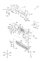
- FIG. 1 is a perspective view of the connector 10 and the connection object 60 according to one embodiment in a separated state in a front view.
- FIG. 2 is a perspective view of the connector 10 and the connection object 60 of FIG. 1 in a separated state in a rear view.
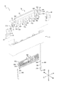
- FIG. 3 is an exploded perspective view showing the connector 10 of FIG. 1 in a front view.
- FIG. 4 is an exploded perspective view showing the connector 10 of FIG. 1 in a rear view.
- the connector 10 includes an insulator 20, a first contact 30A, a second contact 30B, a pressing member 40, and an actuator 50 as large components.
- the connector 10 is assembled by the following method as an example.
- the first contact 30A and the second contact 30B are press-fit into the inside of the insulator 20 from the lower side of the insulator 20.
- the actuator 50 is attached to the insulator 20 from above. At this time, the pressing member 40 engages with the actuator 50, and the upward removal of the actuator 50 is suppressed.
- the connector 10 is mounted on the circuit board CB.
- the connector 10 electrically connects the connection target 60 and the circuit board CB via the first contact 30A and the second contact 30B.
- the insulator 20 is a symmetrical box-shaped member formed by injection molding of an insulating and heat-resistant synthetic resin material.
- the insulator 20 has an insertion groove 21 extending in the insertion / removal direction and recessed in the left-right direction.
- the connection object 60 is inserted into and removed from the insertion groove 21.
- the upper portion of the front surface of the insertion groove 21 is open so that the actuator 50 is attached to the insulator 20.
- the upper edge portion of the rear surface of the insertion groove 21 is formed by an inclined surface which is inclined toward the inside of the insertion groove 21 from the removal side to the insertion side in order to improve the insertability of the connection object 60.
- a substantially central portion in the insertion / extraction direction of the insertion groove 21 is formed by an inclined surface which is further inclined inside the insertion groove 21 from the removal side to the insertion side.
- the longitudinal width of the insertion groove 21 is the largest at the entrance portion, and becomes smaller stepwise by the two inclined surfaces as it goes from the removal side to the insertion side.
- the insulator 20 has a plurality of first attachment grooves 22A extending in the vertical direction in the lower half of the rear surface of the insertion groove 21.
- the plurality of first contacts 30A are press-fit into the plurality of first attachment grooves 22A, respectively.
- the plurality of first attachment grooves 22A are arrayed in the left-right direction at predetermined intervals apart from each other.
- the first mounting groove 22A penetrates the lower surface of the insulator 20 and is recessed to a substantially central portion in the vertical direction of the insertion groove 21.
- the insulator 20 has second attachment grooves 22B extending in the vertical direction on the left and right sides of the rear surface of the insertion groove 21.
- the second contact 30B is press-fit into the second mounting groove 22B.
- the second mounting groove 22B is formed to be recessed to the upper end portion of the insertion groove 21 through the lower surface of the insulator 20.
- the insulator 20 has a third mounting groove 23 formed in a state where the left and right end portions of the front surface are cut wide.
- the pressing member 40 is press-fit into the third mounting groove 23.
- the insulator 20 has a rotation shaft receiving portion 24 at the upper front side which is open for mounting the actuator 50.
- the rotational shaft receiving portions 24 are formed in a total of four in the left half of the insulator 20, two in the right half, and two in the right half.
- the two rotary shaft receivers 24 formed in the left half and the two rotary shaft receivers 24 formed in the right half are substantially line symmetrical with respect to the center of the insulator 20 in the left-right direction. It is formed in position.
- the insulator 20 has a first closed position restricting portion 25A which is formed so as to face the front substantially at the center in the front-rear direction of the left and right end portions.
- the insulator 20 has a second closed position restricting portion 25B spaced apart inward in the left-right direction from the first closed position restricting portion 25A and positioned one step ahead of the first closed position restricting portion 25A.
- the second closed position restricting portion 25B is formed to face forward similarly to the first closed position restricting portion 25A.
- the insulator 20 has support portions 26 formed facing upward on the left and right sides of the third attachment groove 23.
- the insulator 20 is formed discontinuously in the left and right direction at the upper edge of the front surface, and has an open position restricting portion 27 facing upward.
- the first contact 30A has a shape shown in FIGS. 3 and 4 using, for example, a thin plate of a copper alloy or corson based copper alloy having spring elasticity including phosphor bronze, beryllium copper or titanium copper using stamping. Molded into After forming a base by nickel plating, surface layer plating with gold or tin is performed on the surface of the first contact 30A. A plurality of first contacts 30A are arranged in the left-right direction.
- the first contact 30A has a locking portion 31A that locks to the first attachment groove 22A of the insulator 20.
- the first contact 30A has a mounting portion 32A extending rearward in a substantially L shape from the lower end portion of the locking portion 31A.
- the first contact 30A is formed continuously with the upper end portion of the locking portion 31A, and has an elastically deformable elastic portion 33A that extends upward and then bends downward.
- the first contact 30A has a contact portion 34A located at the tip end thereof and formed continuously with the elastic portion 33A.
- the second contact 30B has a shape shown in FIG. 3 and FIG. 4 using, for example, a thin plate of a copper alloy or corson based copper alloy with spring elasticity including phosphor bronze, beryllium copper or titanium copper using stamping. Molded into After forming a base by nickel plating, surface layer plating with gold or tin is performed on the surface of the second contact 30B.
- the second contacts 30 ⁇ / b> B are disposed on the left and right sides of the insulator 20.
- the second contact 30B has a locking portion 31B that locks the second mounting groove 22B of the insulator 20.
- the second contact 30B has a mounting portion 32B extending rearward in a substantially L shape from the lower end portion of the locking portion 31B.
- the second contact 30B is formed continuously with the upper end portion of the locking portion 31B, and has an elastically deformable elastic portion 33B extending upward.
- the second contact 30B has a contact portion 34B located at the tip end thereof and continuously formed with the elastic portion 33B.
- the pressing member 40 is formed by processing a thin plate of any metal material into a shape shown in FIGS. 3 and 4 using a stamping die.
- the pressing member 40 has a locking portion 41 that locks the third mounting groove 23 of the insulator 20.
- the pressing member 40 has a mounting portion 42 extending forward from the lower end portion of the locking portion 41 in a substantially L shape.
- the mounting portion 42 is formed with a through hole.
- the pressing member 40 has an elastically deformable elastic portion 43 extending obliquely upward from a substantially central portion of the locking portion 41.
- the elastic portion 43 is formed so that its tip end extends in a substantially L shape, more specifically, obliquely upward, and then bends in a substantially right direction toward the rear.
- the actuator 50 is a laterally symmetrical plate-like member extending in the left-right direction as shown in FIGS. 3 and 4, which is formed by injection molding of an insulating and heat-resistant synthetic resin material.
- the actuator 50 has an operation portion 51 located at the center and extending in the left-right direction.
- the actuator 50 has a protrusion 52 protruding toward the insertion side. Seven protrusions 52 are formed along the left-right direction, and have protrusions 52A, 52B, 52C, 52D, 52E, 52F and 52G in order from left to right.
- the actuator 50 has four substantially cylindrical rotating shafts 53 which respectively protrude along the left-right direction from the left side surface of the protrusion 52C, the left and right side surfaces of the protrusion 52D, and the right side surface of the protrusion 52E.
- the four rotation shafts 53 are provided in the left-right direction so as to be coaxial with each other.
- the actuator 50 has a first closed position restricted portion 54A which is formed to face the rear in the projection 52A and the projection 52G.
- the actuator 50 has a second closed position restricted portion 54B spaced apart inward from the first closed position restricted portion 54A in the left-right direction and located one step forward of the first closed position restricted portion 54A.
- the second closed position restricted portion 54B is formed to face the rear in the protrusion 52B and the protrusion 52F.
- the actuator 50 has a first holding portion 55A constituted by an inclined surface which is inclined rearward from the tip on the insertion side of the protrusions 52C, 52D and 52E toward the removal side.
- the actuator 50 has a second holding portion 55B configured by the front corners of the protrusions 52A, 52B, 52F and 52G.
- the actuator 50 has a fulcrum 55C configured by the rear corners of the protrusions 52B and 52F.
- the actuator 50 has an open position restricted portion 56 constituted by the slopes of the tops of the protrusions 52C, 52D and 52E.
- the actuator 50 has a cam portion 57 formed so as to be sandwiched by the corresponding pair of projections.
- the cam portion 57 is formed between the lower portion of the protrusion 52A and the lower portion of the protrusion 52B.
- the cam portion 57 is formed between the lower portion of the protrusion 52F and the lower portion of the protrusion 52G.
- the upper edge portion of the cam portion 57 is formed by a curved surface curving in an arc shape.
- the front surface of the cam portion 57 is formed by an inclined surface which is continuous with the curved surface of the upper edge and which is inclined rearward from the removal side toward the insertion side.
- the actuator 50 has a claw-shaped lock portion 58 formed on the removal side relative to the cam portion 57.
- the lock portion 58 protrudes rearward from the upper end of the rear surface of the actuator 50.
- the lock portion 58 constitutes an outer surface on the removal side, and has a curved surface 58A that extends rearward and then curves obliquely downward.
- the outer surface on the removal side of the lock portion 58 is rounded.
- the lock portion 58 constitutes a distal end portion on the insertion side, and has a hook portion 58B projecting to the one-stage insertion side.
- the actuator 50 is formed between the lock portions 58 on both the left and right sides, and has a pressing portion 59 configured by the entire rear surface that inclines rearward from the removal side toward the insertion side.
- connector 10 is mounted on a circuit formation surface formed on the top surface of circuit board CB arranged substantially perpendicular to the insertion and removal direction.
- the mounting portion 32A of the first contact 30A is placed on the solder paste applied to the signal pattern on the circuit board CB.
- the mounting portion 32B of the second contact 30B and the mounting portion 42 of the pressing member 40 are mounted on the solder paste applied to the ground pattern on the circuit board CB.
- the mounting portion 32A is soldered to the signal pattern by heating and melting each solder paste in a reflow furnace or the like.
- the mounting portion 32B and the mounting portion 42 are soldered to the ground pattern.
- the solder is likely to be accumulated by the through holes formed in the mounting portion 42 of the pressing member 40, and the adhesion to the circuit board CB is improved.
- the through holes formed in the mounting portion 42 prevent the excess solder from creeping up. As a result, the spring elasticity of the elastic portion 43 is maintained.
- connection object 60 has a laminated structure in which a plurality of thin film materials are adhered to each other.
- the connection object 60 constitutes a distal end in the extension direction, that is, in the insertion / removal direction, and has a reinforcing portion 61 which is harder than the other portions.
- the connection object 60 has a plurality of signal lines 62 extending linearly along the insertion and removal direction and extending to the lower surface of the reinforcing portion 61.
- the signal line 62 is covered by the exterior of the rear side of the connection object 60 on the removal side, but is exposed to the rear in the vicinity of the tip in the insertion / removal direction.
- the connection object 60 has a contact portion 63 constituted by the side edge portion of the reinforcing portion 61 in the vicinity of the tip end in the insertion and removal direction.
- the connection object 60 is adjacent to the contact portion 63 on the removal side, and has a locked portion 64 formed by cutting out the side edge portion of the reinforcing portion 61.
- the connection object 60 is adjacent to the contact portion 63 on the insertion side, and has a guiding portion 65 formed by cutting out both left and right end portions of the reinforcing portion 61 so as to correspond to the shape of the lock portion 58 of the actuator 50. .
- the outer surface of the connection object 60 in the lead-in portion 65 has an R shape at the tip.
- connection object 60 constitutes a rear surface of the rear exterior and has a ground portion 66 formed in a layer.
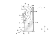
- FIG. 5 is a front view of the connector 10 of FIG. 6 is a cross-sectional view taken along the line VI-VI in FIG. 7 is a cross-sectional view taken along the line VII-VII in FIG.
- FIG. 8 is a cross-sectional view taken along line VIII-VIII in FIG.
- FIG. 9 is a cross-sectional view taken along the line IX-IX in FIG.
- FIG. 10 is a cross-sectional view taken along the line XX in FIG. 11 is a cross-sectional view taken along the line XI-XI in FIG.
- the functions of the components of the connector 10 will be described in detail with reference mainly to FIGS. 5 to 11.
- the first contact 30A when the first contact 30A is press-fit into the first attachment groove 22A of the insulator 20, the first contact 30A can be elastically deformed in the front-rear direction. In the free state where the first contact 30A is not elastically deformed, the contact portion 34A protrudes from the first attachment groove 22A and is positioned in the insertion groove 21.
- the second contact 30 ⁇ / b> B when the second contact 30 ⁇ / b> B is press-fitted into the second attachment groove 22 ⁇ / b> B of the insulator 20, the second contact 30 ⁇ / b> B can be elastically deformed along the front-rear direction. In the free state where the second contact 30B is not elastically deformed, the contact portion 34B protrudes from the second attachment groove 22B and is positioned in the insertion groove 21.
- the rotation shaft 53 of the actuator 50 is received by the rotation shaft receiving portion 24 of the insulator 20.
- the rotation shaft 53 is supported from the insertion side by the rotation shaft receiving portion 24 so that the actuator 50 can rotate between a closed position closed to the insulator 20 and an open position opened to the insulator 20.
- the actuator 50 rotates from the removal side toward the insertion side with respect to the insulator 20 when moving from the closed position to the open position.
- the actuator 50 rotates counterclockwise in FIGS. 6 to 11 when moving from the closed position to the open position.
- the elastic portion 43 of the pressing member 40 is forward due to the inclined surface forming the front surface of the cam portion 57 of the actuator 50.
- the cam portion 57 enters the insertion side more than the substantially L-shaped tip of the elastic portion 43, and the elastic portion 43 and the cam portion 57 are engaged.
- the tip end portion of the elastic portion 43 of the pressing member 40 which has been slightly elastically deformed contacts the cam portion 57 of the actuator 50 from the front.
- a biasing force acts on the actuator 50 via the cam portion 57, and the pressing member 40 rotationally biases the actuator 50 toward the closed position.
- the pressing member 40 allows the actuator 50 to rotate to the open position side by being elastically deformed.
- the first closed position restricting portion 25A of the insulator 20 contacts or approaches the first closed position restricted portion 54A of the actuator 50.
- the second closed position restricting portion 25B of the insulator 20 contacts or approaches the second closed position restricted portion 54B of the actuator 50.
- the first closed position restricting portion 25A and the second closed position restricting portion 25B of the insulator 20 apply, to the actuator 50, a reaction force that balances the biasing force of the pressing member 40 acting on the actuator 50.
- the first closed position restricting portion 25A and the second closed position restricting portion 25B serve to define the closed position of the actuator 50 and to restrict the actuator 50 from rotating excessively beyond the closed position.
- FIG. 12 is a front view of the connector 10 of FIG. 1 when the connection object 60 is inserted.
- FIG. 13 is a cross-sectional view taken along line XIII-XIII of FIG.
- FIG. 14 is a cross-sectional view taken along the line XIV-XIV in FIG.
- FIG. 15 is a cross-sectional view taken along the line XV-XV in FIG. 16 is a cross-sectional view taken along the line XVI-XVI in FIG.
- FIG. 17 is a cross-sectional view taken along line XVII-XVII in FIG.
- FIG. 18 is a cross-sectional view taken along line XVIII-XVIII in FIG.
- the functions of the respective components when the connection object 60 is inserted into the connector 10 will be described in detail with reference mainly to FIGS. 12 to 18.
- connection object 60 When the connection object 60 is inserted into the connector 10, the tip end of the reinforcing portion 61 of the connection object 60 intrudes into the insertion groove 21 along the inclined surface formed on the upper edge of the rear surface of the insertion groove 21. At this time, even if the insertion position of the connection object 60 is slightly shifted backward with respect to the insertion groove 21, the tip of the reinforcing portion 61 slides on the inclined surface of the insertion groove 21, so that the connection object is 60 are drawn into the inside of the insertion groove 21.
- connection at the guiding portion 65 The outer surface of the object 60 slides on the inner surface of the lock portion 58 of the actuator 50, and the connection object 60 is drawn into the insertion groove 21. More specifically, the connection object 60 is moved from the outside to the inside in the left-right direction with reference to the insertion groove 21 by the outer side surface of the inclined connection object 60 constituting the guiding portion 65.
- connection object 60 When the connection object 60 further moves toward the insertion side of the insertion groove 21, the contact portion 63 of the connection object 60 and the lock portion 58 of the actuator 50 contact.
- the outer surface of the lock portion 58 on the removal side is constituted by a curved surface 58A having an R shape, and the contact between the lock portion 58 and the connection object 60 generates a reaction force toward the open position of the actuator 50. Therefore, a moment of force is generated on the actuator 50 toward the open position.
- the actuator 50 moves forward with respect to the insulator 20, as shown in FIG. It rotates to the open position side by the moment of force toward the open position.
- the actuator 50 moves forward and rotates to the open position side, the pressing member 40 is elastically deformed, and an urging force toward the closed position acts on the actuator 50 via the cam portion 57. Therefore, the lock portion 58 of the actuator 50 rides on the front surface of the contact portion 63 of the connection object 60. As the connection object 60 moves toward the insertion side, the contact portion 63 slides relative to the tip of the lock portion 58.
- rotary shafts 53 protruding from the left and right side surfaces of the protrusion 52 ⁇ / b> D are supported by the rotary shaft receiving portion 24 of the insulator 20 from the insertion side.
- the actuator 50 is supported by the insulator 20 in the removal direction from the insertion side.
- the rear surface of the signal line 62 of the connection object 60 contacts the contact portion 34A of the first contact 30A to elastically deform the first contact 30A to the inside of the first attachment groove 22A.
- the ground portion 66 of the connection object 60 contacts the contact portion 34B of the second contact 30B to elastically deform the second contact 30B to the inside of the second mounting groove 22B.
- FIG. 19 is a front view of the connector 10 of FIG. 1 when the connection object 60 is completely inserted.
- FIG. 20 is a cross-sectional view taken along the line XX-XX in FIG.
- FIG. 21 is a cross-sectional view taken along the line XXI-XXI in FIG.
- FIG. 22 is a cross-sectional view taken along line XXII-XXII of FIG.
- the functions of the respective components when the connection object 60 is completely inserted into the connector 10 will be described in detail with reference mainly to FIGS. 19 to 25.
- connection object 60 when connection object 60 is completely inserted into insertion groove 21, contact portion 63 of connection object 60 passes lock portion 58 of actuator 50 and is completely accommodated inside insertion groove 21. Ru. At this time, the lock portion 58 and the contact portion 63 are not in contact with each other, and the biasing force from the pressing member 40 causes the actuator 50 to automatically shift to the lock position.
- the lock position refers to the position of the actuator 50 that holds the connection object 60 inserted into the insertion groove 21 in an interlocking manner. Comparing FIG. 6 to FIG. 11 with FIG. 20 to FIG. 25, in the locked position, the actuator 50 moves slightly ahead of the closed position, and the connection object 60 is moved so that the removal side approaches the connection object 60. Slightly towards.
- the lock portion 58 of the actuator 50 engages with the locked portion 64 of the connection object 60 in the lock position.
- the connection object 60 is retained in the insertion groove 21 by the engagement of the locking portion 58 and the locked portion 64.
- the contact portion 63 of the connection object 60 contacts the hook portion 58B of the lock portion 58 and is directed to the closed position with respect to the actuator 50.
- Generate a moment of force Therefore, the moment of force directed to the open position is suppressed with respect to the actuator 50 which is about to rotate to the open position as the connection object 60 is removed. As a result, the connection object 60 is more effectively retained.
- the connector 10 can hold the connection object 60 only by one operation of inserting the connection object 60 without requiring any operation of the actuator 50 by a worker or an assembling device or the like.
- the inclined surface forming the front surface of the cam portion 57 of the actuator 50 is disposed along the rear surface of the elastic portion 43 of the pressing member 40. Accordingly, the cam portion 57 receives the biasing force from the elastic portion 43 in any manner including point contact, line contact or surface contact. Referring to FIGS. 22 to 25, at this time, the actuator 50 presses the connection target 60 rearward via the pressing portion 59 by the biasing force toward the closed position received from the pressing member 40.
- the contact portion 34A and the signal line 62 of the connection object 60 contact in a state where the second contact 30B is elastically deformed.
- the circuit board CB on which the connector 10 is mounted and the connection target 60 are electrically connected to each other through the first contact 30A and the second contact 30B.
- the contact between the contact portion 34B and the ground portion 66 causes the connection object 60 to be grounded to the circuit board CB via the connector 10.
- FIG. 26 is a front view of the connector 10 of FIG. 1 when the connection object 60 is removed.
- FIG. 27 is a cross-sectional view taken along line XXVII-XXVII in FIG.
- FIG. 28 is a cross-sectional view taken along line XXVIII-XXVIII in FIG.
- FIG. 29 is a cross-sectional view taken along line XXIX-XXIX in FIG.
- FIG. 30 is a cross-sectional view taken along the line XXX-XXX in FIG. 31 is a cross-sectional view taken along the line XXI-XXI in FIG. 32 is a cross-sectional view taken along line XXII-XXXII of FIG.
- the functions of the respective components when the connection object 60 is removed from the connector 10 will be described in detail with reference mainly to FIGS.
- the actuator 50 In the connector 10, in a state where the connection object 60 is completely inserted into the insertion groove 21, when the operator or the assembling device operates the operation portion 51 of the actuator 50 to rotate the actuator 50 to the open position, the actuator 50 holds the open position independently. Referring to FIG. 28, when the actuator 50 is in the open position, the pressing member 40 is elastically deformed to a large extent, and an urging force toward the closed position acts on the actuator 50 through the cam portion 57. On the other hand, referring to FIG. 31, when the actuator 50 is in the open position, the first holding portion 55A of the actuator 50 contacts the front surface of the reinforcing portion 61 of the connection object 60 inserted into the insulator 20.
- the second holding portion 55B of the actuator 50 is located on the insertion side of the cam portion 57 and contacts the support portion 26 of the insulator 20.
- the actuator 50 is supported by the insulator 20 from the insertion side along the insertion and removal direction.
- the open position restricted portion 56 of the actuator 50 contacts or approaches the open position restricting portion 27 of the insulator 20.
- the open position restricting portion 27 serves to define the open position of the actuator 50 and to restrict the actuator 50 from excessively rotating beyond the open position. As a result, the open position restricting portion 27 can suppress damage to the respective members such as the insulator 20 and the actuator 50.
- connection object 60 When the connection object 60 is removed with the actuator 50 in the open position, the front surface of the reinforcing portion 61 of the connection object 60 slides against the first holding portion 55A of the actuator 50, and then the first holding portion 55A and The connection object 60 is in a non-contact state. At this time, the actuator 50 slightly moves rearward from the open position shown in FIGS. 27 to 32, and the fulcrum 55C shown in FIG. 29 contacts the second closed position restricting portion 25B of the insulator 20. The actuator 50 is automatically returned to the closed position by the biasing force from the pressing member 40 with the fulcrum 55C as a fulcrum.
- the connector 10 According to the connector 10 according to the embodiment as described above, the workability at the time of removing the connection object 60 is improved.
- the operator or the assembly apparatus rotates the actuator to the open position and takes it to the open position when removing the connection object. While performing the holding operation, it is necessary to perform the operation of removing the connection object from the connector in parallel. The worker needs to operate with both hands, for example. The assembling apparatus needs to operate using, for example, two working arms.
- the actuator 50 holds the open position in a self-supporting manner, whereby the operator or the assembling apparatus etc. performs an operation of holding the actuator 50 in the open position when removing the connection object 60.
- the operator can perform the operation of removing the connection object 60 from the connector 10 with the same hand.
- the assembling apparatus can perform an operation of removing the connection object 60 from the connector 10 using the same work arm after rotating the actuator 50 to the open position using only one work arm, for example.
- the working space for operating the actuator 50 on the circuit board CB can be reduced by rotating the actuator 50 from the removal side toward the insertion side when the actuator 50 moves from the closed position to the open position.
- the actuator rotates from the insertion side to the removal side.
- the opening of the insertion groove faces, for example, the outside of the circuit board.
- the operating portion of the actuator is disposed inside the circuit board. Therefore, the worker or the assembling device etc. needs to operate the actuator inside the circuit board. As a result, a working space is required in the area inside the connector on the circuit board.
- the operating portion 51 of the actuator 50 is disposed at the end of the circuit board CB and faces outward even if the connector 10 is disposed in the same manner as the conventional connector described above. Therefore, the worker or the assembling apparatus can operate the actuator 50 outside the circuit board CB. As a result, no work space on the circuit board CB is required. Thus, the connector 10 can contribute to space saving on the circuit board CB.
- the connector 10 connects the connection object 60 to the circuit board CB by rotating from the removal side toward the insertion side when the actuator 50 shifts from the closed position to the open position.
- both vertical and parallel directions can be accommodated.
- the actuator 50 rotates and automatically returns to the closed position, whereby the operator or the assembling device etc. performs an operation to return the actuator 50 to the closed position. There is no need to do it.
- the operator can return the actuator 50 to the closed position only by removing the connection object 60 from the connector 10.
- the assembling apparatus can return the actuator 50 to the closed position only by performing an operation of removing the connection object 60 from the connector 10 after rotating the actuator 50 to the open position using, for example, one work arm. it can.
- the moment of force generated at each of the cam portion 57 in contact with the pressing member 40 and the first holding portion 55A in contact with the connection object 60 at the open position is canceled, and the actuator 50 can stably hold the open position.
- the actuator 50 is stably supported in the removal direction from the insertion side at the open position by the second holding portion 55B in contact with the support portion 26 of the insulator 20.
- the actuator 50 can be stably rotated with the fulcrum 55C as a fulcrum by the fulcrum 55C in contact with the insulator 20 when rotating.
- the actuator 50 can stably rotate to the closed position by the biasing force from the pressing member 40 with the fulcrum 55C as a fulcrum.
- connection object 60 By the connection object 60 being held by the lock portion 58 only by one operation of inserting the connection object 60, the connector 10 can be operated not only when removing the connection object 60 but also when inserting it. Also improve.
- the operator and the assembling apparatus do not need to rotate the actuator 50 to the open position side and perform an operation to hold the state. Therefore, the operator can perform an operation of inserting the connection object 60 into the connector 10 with one hand, for example.
- the assembling apparatus can perform an operation of inserting the connection object 60 into the connector 10 using only one working arm, for example.
- connection object 60 having the induction portion 65 corresponding to the shape of the lock portion 58 of the actuator 50 improves the insertability of the connection object 60 into the connector 10.
- the shape, arrangement, number, and the like of each component described above are not limited to the contents described above and illustrated in the drawings.
- the shape, arrangement, number and the like of each component may be arbitrarily configured as long as the function can be realized.
- the method of assembling the connector 10 described above is not limited to the contents of the above description.
- the method of assembling the connector 10 may be any method as long as it can be assembled so that the respective functions can be exhibited.
- the first contact 30A, the second contact 30B, and the pressing member 40 may be integrally formed with the insulator 20 by insert molding instead of press fitting.
- the connector 10 or the connection object 60 as described above is mounted on an electronic device.
- the electronic device includes, for example, any information device such as a personal computer, a copier, a printer, a facsimile, or a multifunction device.
- Electronic devices include any audiovisual equipment such as liquid crystal televisions, recorders, cameras or headphones.
- the electronic device includes, for example, any on-vehicle device such as a camera, a radar, a drive recorder or an engine control unit.
- the electronic device includes, for example, any in-vehicle device used in an in-vehicle system such as a car navigation system, an advanced driving support system or a security system.
- the electronic device includes any industrial device.
- Such an electronic device improves the workability at the time of assembling the electronic device by the workability improvement by the connector 10 and the insertability of the connection object 60. The manufacture of the electronic device is facilitated.
Landscapes
- Coupling Device And Connection With Printed Circuit (AREA)
- Details Of Connecting Devices For Male And Female Coupling (AREA)
Abstract
本開示に係るコネクタ(10)は、接続対象物(60)を挿入及び抜去可能なインシュレータ(20)と、インシュレータ(20)に対して閉じる閉位置とインシュレータ(20)に対して開く開位置との間を回動可能なアクチュエータ(50)と、を備え、アクチュエータ(50)は、閉位置から開位置へと移行する際にインシュレータ(20)に対する接続対象物(60)の抜去側から挿入側に向けて回転し、開位置を自立して保持する。
Description
本出願は、2017年11月1日に日本国に特許出願された特願2017-211826の優先権を主張するものであり、この出願の開示全体をここに参照のために取り込む。
本開示は、コネクタ、接続対象物及び電子機器に関する。
従来、電子機器等に用いられるコネクタでは、作業性向上の観点から接続対象物を容易に挿抜できるような構造が要求される。電子機器等の製造において作業者の手を介さず機械によって自動的に全ての工程が行われるような場合、及び機器のメンテナンス時に手作業にて挿抜する場合など、作業性向上に関する上記のコネクタへの要求はさらに高まる。
例えば、特許文献1に記載のケーブル用コネクタでは、接続対象物を挿入するという1回の動作によってケーブル用コネクタと接続対象物とが確実に接続される。
本開示の一実施形態に係るコネクタは、
接続対象物を挿入及び抜去可能なインシュレータと、
前記インシュレータに対して閉じる閉位置と前記インシュレータに対して開く開位置との間を回動可能なアクチュエータと、
を備え、
前記アクチュエータは、前記閉位置から前記開位置へと移行する際に前記インシュレータに対する前記接続対象物の抜去側から挿入側に向けて回転し、前記開位置を自立して保持する。
接続対象物を挿入及び抜去可能なインシュレータと、
前記インシュレータに対して閉じる閉位置と前記インシュレータに対して開く開位置との間を回動可能なアクチュエータと、
を備え、
前記アクチュエータは、前記閉位置から前記開位置へと移行する際に前記インシュレータに対する前記接続対象物の抜去側から挿入側に向けて回転し、前記開位置を自立して保持する。
特許文献1に記載のケーブル用コネクタでは、接続対象物を挿入する際の作業性は向上するものの、接続対象物を抜去する際の作業性については考慮されていなかった。
本開示の一実施形態に係るコネクタによれば、接続対象物を抜去する際の作業性が向上する。
以下、添付図面を参照しながら本開示の一実施形態について詳細に説明する。以下の説明中の前後、左右及び上下の方向は、図中の矢印の方向を基準とする。各矢印の方向は、図1乃至図32において、異なる図面同士で互いに整合している。図面によっては、簡便な図示を目的として、回路基板CBの図示を省略する。
一実施形態に係るコネクタ10と接続される接続対象物60は、一例として、フレキシブルプリント回路基板(FPC)であるとして説明するがこれに限定されない。接続対象物60は、コネクタ10を介して回路基板CBと電気的に接続されるものであれば、任意の対象物であってよい。例えば、接続対象物60は、フレキシブルフラットケーブル(FFC)であってもよい。
以下、接続対象物60は、コネクタ10が実装されている回路基板CBに対して垂直方向にコネクタ10と接続されるとして説明する。接続対象物60は、一例として上下方向に沿ってコネクタ10と接続される。以下で使用する「挿抜方向」は、一例として上下方向を指すとする。「抜去方向」は、一例として上方向を指すとする。「挿入側」は、下側を指すとする。「抜去側」は、上側を指すとする。接続方法は、これに限定されない。接続対象物60は、回路基板CBに対して平行方向にコネクタ10と接続されてもよい。回路基板CBは、リジッド基板であってよいし、又はそれ以外の任意の回路基板であってもよい。
図1は、一実施形態に係るコネクタ10及び接続対象物60を正面視によって示した分離状態の斜視図である。図2は、図1のコネクタ10及び接続対象物60を背面視によって示した分離状態の斜視図である。図3は、図1のコネクタ10を正面視によって示した分解斜視図である。図4は、図1のコネクタ10を背面視によって示した分解斜視図である。図1乃至図4を参照しながら、一実施形態に係るコネクタ10及び接続対象物60の構成について詳細に説明する。
図3及び図4を参照すると、一実施形態に係るコネクタ10は、大きな構成要素としてインシュレータ20と、第1コンタクト30Aと、第2コンタクト30Bと、押圧部材40と、アクチュエータ50とを有する。コネクタ10は、一例として以下の方法で組み立てられる。インシュレータ20の下方から第1コンタクト30A及び第2コンタクト30Bをインシュレータ20の内部に圧入する。押圧部材40を上方からインシュレータ20に圧入したのち、アクチュエータ50を上方からインシュレータ20に取り付ける。このとき、押圧部材40がアクチュエータ50と係合し、アクチュエータ50の上方への抜けが抑制される。図1及び図2を参照すると、コネクタ10は、回路基板CB上に実装される。コネクタ10は、第1コンタクト30A及び第2コンタクト30Bを介して接続対象物60と回路基板CBとを電気的に接続する。
図3を参照すると、インシュレータ20は、絶縁性かつ耐熱性の合成樹脂材料を射出成形した左右対称の箱形の部材である。インシュレータ20は、挿抜方向に延在し、左右方向にわたって凹設されている挿入溝21を有する。挿入溝21に対して、接続対象物60が挿入及び抜去される。挿入溝21の前面の上部は、インシュレータ20にアクチュエータ50が取り付けられるよう開放されている。挿入溝21の後面の上縁部は、接続対象物60の挿入性を向上させるために、抜去側から挿入側に向けて挿入溝21の内側に傾斜する傾斜面によって形成されている。挿入溝21の挿抜方向における略中央部は、抜去側から挿入側に向けて挿入溝21の内側にさらに傾斜する傾斜面によって形成されている。挿入溝21の前後幅は、入り口部分において最も大きく、抜去側から挿入側に向かうにつれ2つの傾斜面によって段階的に小さくなる。
インシュレータ20は、挿入溝21の後面の下半部において上下方向に延在する複数の第1取付溝22Aを有する。複数の第1取付溝22Aには、複数の第1コンタクト30Aがそれぞれ圧入される。複数の第1取付溝22Aは、互いに所定の間隔で離間して左右方向に配列している。第1取付溝22Aは、インシュレータ20の下面を貫通して挿入溝21の上下方向における略中央部まで凹設されている。インシュレータ20は、挿入溝21の後面の左右両側において上下方向に延在する第2取付溝22Bを有する。第2取付溝22Bには、第2コンタクト30Bが圧入される。第2取付溝22Bは、インシュレータ20の下面を貫通して挿入溝21の上端部まで凹設されている。インシュレータ20は、前面の左右両端部を幅広に切り欠いた状態で形成されている第3取付溝23を有する。第3取付溝23には、押圧部材40が圧入される。
インシュレータ20は、アクチュエータ50が取り付けられるよう開放されている前側上部において、回転軸受容部24を有する。回転軸受容部24は、インシュレータ20の左半部に2つ、右半部に2つ、合計で4つ形成されている。左半部に形成されている2つの回転軸受容部24と右半部に形成されている2つの回転軸受容部24とは、インシュレータ20の左右方向の中心を基準として互いに略線対称となる位置に形成されている。インシュレータ20は、左右両端部の前後方向略中央において前方を向いて形成されている第1閉位置規制部25Aを有する。インシュレータ20は、第1閉位置規制部25Aから左右方向に沿って内側に離間し、かつ第1閉位置規制部25Aよりも一段前方に位置する第2閉位置規制部25Bを有する。第2閉位置規制部25Bは、第1閉位置規制部25Aと同様に前方を向いて形成されている。インシュレータ20は、第3取付溝23の左右両側で上方を向いて形成されている支持部26を有する。インシュレータ20は、前面の上縁部において左右方向に不連続に形成され、上方を向いている開位置規制部27を有する。
第1コンタクト30Aは、例えば、リン青銅、ベリリウム銅若しくはチタン銅を含むばね弾性を備えた銅合金又はコルソン系銅合金の薄板を順送金型(スタンピング)を用いて図3及び図4に示す形状に成形加工したものである。第1コンタクト30Aの表面には、ニッケルめっきで下地を形成した後に、金又は錫等による表層めっきが施されている。第1コンタクト30Aは、左右方向に沿って複数配列されている。
第1コンタクト30Aは、インシュレータ20の第1取付溝22Aに対して係止する係止部31Aを有する。第1コンタクト30Aは、係止部31Aの下端部から略L字状に後方に延出する実装部32Aを有する。第1コンタクト30Aは、係止部31Aの上端部と連続して形成され、上方に向けて延出した後に下方に向けて屈曲する弾性変形可能な弾性部33Aを有する。第1コンタクト30Aは、その先端部に位置し、弾性部33Aと連続して形成されている接触部34Aを有する。
第2コンタクト30Bは、例えば、リン青銅、ベリリウム銅若しくはチタン銅を含むばね弾性を備えた銅合金又はコルソン系銅合金の薄板を順送金型(スタンピング)を用いて図3及び図4に示す形状に成形加工したものである。第2コンタクト30Bの表面には、ニッケルめっきで下地を形成した後に、金又は錫等による表層めっきが施されている。第2コンタクト30Bは、インシュレータ20の左右両側に配置されている。
第2コンタクト30Bは、インシュレータ20の第2取付溝22Bに対して係止する係止部31Bを有する。第2コンタクト30Bは、係止部31Bの下端部から略L字状に後方に延出する実装部32Bを有する。第2コンタクト30Bは、係止部31Bの上端部と連続して形成され、上方に向けて延出する弾性変形可能な弾性部33Bを有する。第2コンタクト30Bは、その先端部に位置し、弾性部33Bと連続して形成されている接触部34Bを有する。
押圧部材40は、任意の金属材料の薄板を順送金型(スタンピング)を用いて図3及び図4に示す形状に成形加工したものである。押圧部材40は、インシュレータ20の第3取付溝23に対して係止する係止部41を有する。押圧部材40は、係止部41の下端部から略L字状に前方に延出する実装部42を有する。実装部42は貫通孔が形成されている。押圧部材40は、係止部41の略中央部から斜め上方に延出する、弾性変形可能な弾性部43を有する。弾性部43は、先端が略L字状、より具体的には斜め上方に向けて延伸した後、後方に向けて略直角に屈曲するように形成されている。
アクチュエータ50は、絶縁性かつ耐熱性の合成樹脂材料を射出成形した、図3及び図4に示すような左右方向に延びる左右対称の板状部材である。アクチュエータ50は、中央部に位置し、左右方向に延びる操作部51を有する。アクチュエータ50は、挿入側に突出した突部52を有する。突部52は、左右方向に沿って7つ形成されており、左から右へ順に突部52A、52B、52C、52D、52E、52F及び52Gを有する。
アクチュエータ50は、突部52Cの左側面、突部52Dの左右両側面及び突部52Eの右側面から左右方向に沿ってそれぞれ突出する略円柱形状の4つの回転軸53を有する。4つの回転軸53は、互いに同軸をなしながら左右方向に突設される。アクチュエータ50は、突部52A及び突部52Gにおいて後方を向いて形成されている第1閉位置被規制部54Aを有する。アクチュエータ50は、第1閉位置被規制部54Aから左右方向に沿って内側に離間し、かつ第1閉位置被規制部54Aよりも一段前方に位置する第2閉位置被規制部54Bを有する。第2閉位置被規制部54Bは、突部52B及び突部52Fにおいて後方を向いて形成されている。アクチュエータ50は、突部52C、52D及び52Eの挿入側の先端から抜去側に向けて後方に傾斜する傾斜面により構成される第1保持部55Aを有する。アクチュエータ50は、突部52A、52B、52F及び52Gの前側の角部によって構成される第2保持部55Bを有する。アクチュエータ50は、突部52B及び52Fの後側の角部によって構成される支点部55Cを有する。アクチュエータ50は、突部52C、52D及び52Eの最上部の斜面によって構成される開位置被規制部56を有する。
アクチュエータ50は、対応する一対の突部によって挟まれるように形成されているカム部57を有する。カム部57は、突部52Aの下部と突部52Bの下部との間に形成されている。カム部57は、突部52Fの下部と突部52Gの下部との間に形成されている。カム部57の上縁部は、円弧状に湾曲する曲面により形成されている。カム部57の前面は、上縁部の曲面と連続し、抜去側から挿入側に向けて後方に傾斜する傾斜面によって形成されている。アクチュエータ50は、カム部57よりも抜去側に形成されている爪状のロック部58を有する。ロック部58は、アクチュエータ50の後面の上端部から後方に向けて突出する。ロック部58は、抜去側の外面を構成し、後方に延出した後斜め下方に向けて湾曲する曲面58Aを有する。ロック部58の抜去側の外面はR形状となる。ロック部58は、挿入側の先端部を構成し、一段挿入側に突出する引っ掛かり部58Bを有する。アクチュエータ50は、左右両側のロック部58の間に形成され、抜去側から挿入側に向けて後方に傾斜する後面全体により構成される押圧部59を有する。
図1及び図2を参照すると、コネクタ10は、挿抜方向に対して略垂直に配置される回路基板CBの上面に形成された回路形成面に対して実装される。具体的には、第1コンタクト30Aの実装部32Aは、回路基板CB上の信号パターンに塗布したはんだペーストに載置される。第2コンタクト30Bの実装部32B及び押圧部材40の実装部42は、回路基板CB上の接地パターンに塗布したはんだペーストに載置される。リフロー炉等において各はんだペーストを加熱溶融することで、実装部32Aは、上記信号パターンにはんだ付けされる。実装部32B及び実装部42は、上記接地パターンにはんだ付けされる。結果、コネクタ10の回路基板CBへの実装が完了する。このとき、押圧部材40の実装部42に形成されている貫通孔によってはんだが溜まりやすくなり、回路基板CBに対する固着力が向上する。同時に、実装部42に形成されている貫通孔によって余剰はんだの這い上がりが抑制される。結果として、弾性部43のばね弾性が維持される。
接続対象物60は、複数の薄膜材を互いに接着して構成した積層構造を有する。接続対象物60は、延長方向、すなわち挿抜方向の先端部を構成しかつその他の部分に比べて硬い補強部61を有する。接続対象物60は、挿抜方向に沿って直線的に延びかつ補強部61の下面まで延びる複数の信号線62を有する。信号線62は、抜去側では接続対象物60の後側の外装によって覆われているが、挿抜方向の先端付近において後方に露出している。接続対象物60は、挿抜方向の先端付近において、補強部61の側縁部により構成される接触部63を有する。接続対象物60は、接触部63と抜去側で隣接し、補強部61の側縁部を切り欠いて形成されている被ロック部64を有する。接続対象物60は、接触部63と挿入側で隣接し、アクチュエータ50のロック部58の形状と対応するように補強部61の左右両先端部を切り欠いて形成されている誘い込み部65を有する。誘い込み部65における接続対象物60の外側面は、先端においてR形状となる。当該外側面は、先端から挿抜方向に沿って抜去側に延びた後、抜去側にさらに向かうにつれて外側に傾斜する。接続対象物60は、後側の外装の後面を構成し、層状に形成されている接地部66を有する。
図5は、図1のコネクタ10の正面図である。図6は、図5のVI-VI矢線に沿う断面図である。図7は、図5のVII-VII矢線に沿う断面図である。図8は、図5のVIII-VIII矢線に沿う断面図である。図9は、図5のIX-IX矢線に沿う断面図である。図10は、図5のX-X矢線に沿う断面図である。図11は、図5のXI-XI矢線に沿う断面図である。主に図5乃至図11を参照しながら、コネクタ10の各構成部の機能について詳細に説明する。
図9乃至図11を参照すると、第1コンタクト30Aがインシュレータ20の第1取付溝22Aに圧入された場合、第1コンタクト30Aは、前後方向に沿って弾性変形可能である。第1コンタクト30Aが弾性変形していない自由状態にあっては、接触部34Aは第1取付溝22Aから突出して挿入溝21内に位置する。図8を参照すると、第2コンタクト30Bがインシュレータ20の第2取付溝22Bに圧入された場合、第2コンタクト30Bは、前後方向に沿って弾性変形可能である。第2コンタクト30Bが弾性変形していない自由状態にあっては、接触部34Bは第2取付溝22Bから突出して挿入溝21内に位置する。
図11を参照すると、アクチュエータ50がインシュレータ20に取り付けられた場合、アクチュエータ50の回転軸53がインシュレータ20の回転軸受容部24に受け入れられる。回転軸53が回転軸受容部24によって挿入側から支持されることで、アクチュエータ50は、インシュレータ20に対して閉じる閉位置とインシュレータ20に対して開く開位置との間を回動可能となる。一実施形態に係るコネクタ10では、アクチュエータ50は、閉位置から開位置へと移行する際にインシュレータ20に対して抜去側から挿入側に向けて回転する。アクチュエータ50は、閉位置から開位置へと移行する際に、図6乃至図11において反時計回りに回転する。
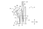
図7を参照すると、押圧部材40が圧入されたインシュレータ20に上方からアクチュエータ50を取り付ける際、アクチュエータ50のカム部57の前面を形成している傾斜面によって、押圧部材40の弾性部43が前方に弾性変形する。弾性部43が前方に弾性変位することで、カム部57が弾性部43の略L字状の先端よりも挿入側に入り込み、弾性部43とカム部57とが係合する。このとき、若干弾性変形した押圧部材40の弾性部43の先端部がアクチュエータ50のカム部57に対して前方から接触する。これにより、カム部57を介してアクチュエータ50に付勢力が働き、押圧部材40は、アクチュエータ50を閉位置に向けて回転付勢する。押圧部材40は、弾性変形することによりアクチュエータ50の開位置側への回転を許容する。
図6を参照すると、アクチュエータ50が閉位置にある場合、インシュレータ20の第1閉位置規制部25Aとアクチュエータ50の第1閉位置被規制部54Aとが接触又は近接する。同様に、図8を参照すると、アクチュエータ50が閉位置にある場合、インシュレータ20の第2閉位置規制部25Bとアクチュエータ50の第2閉位置被規制部54Bとが接触又は近接する。インシュレータ20の第1閉位置規制部25A及び第2閉位置規制部25Bは、押圧部材40からアクチュエータ50に作用する付勢力とつり合う抗力をアクチュエータ50に加える。第1閉位置規制部25A及び第2閉位置規制部25Bは、アクチュエータ50の閉位置を定めて、アクチュエータ50が当該閉位置を超えて過剰に回転することを規制する役割を果たす。
図12は、接続対象物60が挿入される際の図1のコネクタ10の正面図である。図13は、図12のXIII-XIII矢線に沿う断面図である。図14は、図12のXIV-XIV矢線に沿う断面図である。図15は、図12のXV-XV矢線に沿う断面図である。図16は、図12のXVI-XVI矢線に沿う断面図である。図17は、図12のXVII-XVII矢線に沿う断面図である。図18は、図12のXVIII-XVIII矢線に沿う断面図である。主に図12乃至図18を用いて、接続対象物60がコネクタ10に挿入される際の各構成部の機能について詳細に説明する。
接続対象物60がコネクタ10に挿入される際、接続対象物60の補強部61の先端が挿入溝21の後面の上縁部に形成された傾斜面に沿って挿入溝21内に侵入する。このとき、仮に接続対象物60の挿入位置が挿入溝21に対して後方に若干ずれていたとしても、補強部61の先端が挿入溝21の傾斜面上を摺動することで、接続対象物60が挿入溝21の内部に誘い込まれる。同様に、仮に接続対象物60の挿入位置が挿入溝21に対して左右方向に若干ずれていたり、接続対象物60が左右に向けて挿抜方向から若干傾いていたとしても、誘い込み部65における接続対象物60の外側面がアクチュエータ50のロック部58の内側面上を摺動して、接続対象物60が挿入溝21の内部に誘い込まれる。より具体的には、誘い込み部65を構成する傾斜した接続対象物60の外側面によって、挿入溝21を基準とした左右方向における外側から内側へと接続対象物60が移動する。
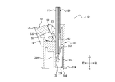
接続対象物60が挿入溝21の挿入側へとさらに移動すると、接続対象物60の接触部63とアクチュエータ50のロック部58とが接触する。ロック部58の抜去側の外面はR形状をなす曲面58Aにより構成されており、ロック部58と接続対象物60との接触によってアクチュエータ50の開位置に向けた抗力が発生する。したがって、アクチュエータ50に対して開位置に向けた力のモーメントが生じる。ロック部58と接触部63とが接触した状態で挿入溝21のさらに挿入側へと接続対象物60が移動すると、図14に示すとおり、アクチュエータ50がインシュレータ20に対して前方へ移動すると共に、開位置に向けた力のモーメントによって開位置側へ回転する。一方で、アクチュエータ50が前方へ移動し、かつ開位置側へ回転することで押圧部材40が弾性変形し、閉位置に向けた付勢力がカム部57を介してアクチュエータ50に働く。したがって、アクチュエータ50のロック部58は、接続対象物60の接触部63の前面に乗り上げる。接続対象物60の挿入側への移動に伴って、接触部63は、ロック部58の先端部分に対して摺動する。
図18を参照すると、突部52Dの左右両側面に突設された回転軸53がインシュレータ20の回転軸受容部24によって挿入側から支持される。アクチュエータ50は、インシュレータ20により挿入側から抜去方向に支持される。
図16乃至図18を参照すると、接続対象物60の信号線62の後面が第1コンタクト30Aの接触部34Aと接触して第1コンタクト30Aを第1取付溝22Aの内側へと弾性変形させる。同様に、図15を参照すると、接続対象物60の接地部66が第2コンタクト30Bの接触部34Bと接触して第2コンタクト30Bを第2取付溝22Bの内側へと弾性変形させる。
図19は、接続対象物60が完全に挿入された際の図1のコネクタ10の正面図である。図20は、図19のXX-XX矢線に沿う断面図である。図21は、図19のXXI-XXI矢線に沿う断面図である。図22は、図19のXXII-XXII矢線に沿う断面図である。図23は、図19のXXIII-XXIII矢線に沿う断面図である。図24は、図19のXXIV-XXIV矢線に沿う断面図である。図25は、図19のXXV-XXV矢線に沿う断面図である。主に図19乃至図25を用いて、接続対象物60がコネクタ10に完全に挿入された際の各構成部の機能について詳細に説明する。
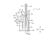
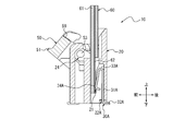
図21を参照すると、接続対象物60が挿入溝21に完全に挿入された場合、接続対象物60の接触部63がアクチュエータ50のロック部58を通り過ぎて挿入溝21の内部に完全に収容される。このとき、ロック部58と接触部63とが非接触状態となり、押圧部材40からの付勢力によってアクチュエータ50がロック位置へと自動的に移行する。ロック位置とは、挿入溝21に挿入された接続対象物60を抜止保持するアクチュエータ50の位置を意味する。図6乃至図11と図20乃至図25とをそれぞれ比較すると、ロック位置では、アクチュエータ50は、閉位置よりも若干前方に移動し、かつ抜去側が接続対象物60に近接するよう接続対象物60に向けて若干傾く。アクチュエータ50のロック部58は、ロック位置において接続対象物60の被ロック部64と係合する。接続対象物60は、ロック部58と被ロック部64との係合により挿入溝21内で抜止保持される。このような状態で、仮に接続対象物60を無理に抜去しようとしても、接続対象物60の接触部63がロック部58の引っ掛かり部58Bに接触して、アクチュエータ50に対して閉位置に向けた力のモーメントを発生させる。したがって、接続対象物60の抜去に伴って開位置へと回転しようとするアクチュエータ50に対して開位置に向けた力のモーメントが抑制される。結果、接続対象物60がより効果的に抜止保持される。
このように、コネクタ10は、作業者又は組立装置等によるアクチュエータ50の任意の操作を必要とすることなく、接続対象物60を挿入するという1つの動作のみによって接続対象物60を抜止保持する。アクチュエータ50がロック位置にあるとき、アクチュエータ50のカム部57の前面を形成している傾斜面は、押圧部材40の弾性部43の後面に沿って配置される。したがって、カム部57は、点接触、線接触又は面接触を含む任意の態様で弾性部43からの付勢力を受ける。図22乃至図25を参照すると、このとき、アクチュエータ50は、押圧部材40から受ける閉位置に向けた付勢力によって、押圧部59を介して接続対象物60を後方へと押圧する。
図23乃至図25を参照すると、第1コンタクト30Aが弾性変形した状態で、接触部34Aと接続対象物60の信号線62とが接触する。同様に、図22を参照すると、第2コンタクト30Bが弾性変形した状態で、接触部34Bと接続対象物60の接地部66とが接触する。以上により、コネクタ10が実装された回路基板CBと接続対象物60とが第1コンタクト30A及び第2コンタクト30Bを介して互いに電気的に接続される。接触部34Bと接地部66との接触により、接続対象物60がコネクタ10を介して回路基板CBに接地される。このように、接地部66を信号線62と異なる位置に形成して回路基板CBに接地させることで、高速伝送においてもノイズが低減する。
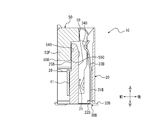
図26は、接続対象物60が抜去される際の図1のコネクタ10の正面図である。図27は、図26のXXVII-XXVII矢線に沿う断面図である。図28は、図26のXXVIII-XXVIII矢線に沿う断面図である。図29は、図26のXXIX-XXIX矢線に沿う断面図である。図30は、図26のXXX-XXX矢線に沿う断面図である。図31は、図26のXXXI-XXXI矢線に沿う断面図である。図32は、図26のXXXII-XXXII矢線に沿う断面図である。主に図26乃至図32を用いて、接続対象物60がコネクタ10から抜去される際の各構成部の機能について詳細に説明する。
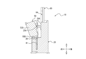
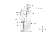
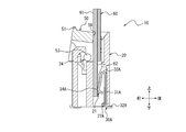
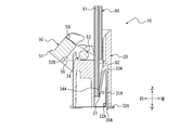
コネクタ10では、接続対象物60が挿入溝21に完全に挿入されている状態で、作業者又は組立装置等がアクチュエータ50の操作部51を操作してアクチュエータ50を開位置まで回転させると、アクチュエータ50は開位置を自立して保持する。図28を参照すると、アクチュエータ50が開位置にあることで押圧部材40が大きく弾性変形し、閉位置に向けた付勢力がカム部57を介してアクチュエータ50に働く。一方で、図31を参照すると、アクチュエータ50が開位置にある場合、アクチュエータ50の第1保持部55Aは、インシュレータ20に挿入された接続対象物60の補強部61の前面と接触する。このとき、押圧部材40の弾性部43からカム部57を介してアクチュエータ50に働く付勢力と接続対象物60の補強部61の前面から第1保持部55Aを介してアクチュエータ50に働く抗力とがつり合うことで力のモーメントが打ち消される。したがって、アクチュエータ50の回転が抑制され、アクチュエータ50は開位置を自立して保持する。このように力のモーメントを打ち消して効果的にアクチュエータ50の回転を抑制するために、アクチュエータ50の回転軸53、第1保持部55A及びカム部57と押圧部材40との接点は、アクチュエータ50が開位置にある場合、挿抜方向において互いに略同一の位置にある。
図27乃至図29を参照すると、アクチュエータ50が開位置にある場合、アクチュエータ50の第2保持部55Bは、カム部57よりも挿入側に位置し、インシュレータ20の支持部26と接触する。これにより、アクチュエータ50は、挿抜方向に沿って挿入側からインシュレータ20により支持される。
図31を参照すると、アクチュエータ50が開位置にある場合、アクチュエータ50の開位置被規制部56は、インシュレータ20の開位置規制部27と接触又は近接する。開位置規制部27は、アクチュエータ50の開位置を定めて、アクチュエータ50が当該開位置を超えて過剰に回転することを規制する役割を果たす。これにより、開位置規制部27は、インシュレータ20及びアクチュエータ50等の各部材の破損を抑制できる。
アクチュエータ50が開位置にある状態で接続対象物60を抜去すると、接続対象物60の補強部61の前面がアクチュエータ50の第1保持部55Aに対して摺動した後、第1保持部55Aと接続対象物60とが非接触状態となる。このとき、アクチュエータ50は、図27乃至図32に示す開位置から後方に若干移動し、図29に示す支点部55Cがインシュレータ20の第2閉位置規制部25Bと接触する。アクチュエータ50は、支点部55Cを支点として押圧部材40からの付勢力により閉位置へと自動的に復帰する。
以上のような一実施形態に係るコネクタ10によれば、接続対象物60を抜去する際の作業性が向上する。アクチュエータ50が開位置を自立して保持することができないような従来のコネクタの場合、作業者又は組立装置等は、接続対象物を抜去する際に、アクチュエータを開位置まで回転させて開位置に保持する操作を行いながら、接続対象物をコネクタから抜去する操作を並行して行う必要がある。作業者は、例えば両手で操作を行う必要がある。組立装置は、例えば2つの作業アームを用いて操作を行う必要がある。一実施形態に係るコネクタ10では、アクチュエータ50が開位置を自立して保持することで、作業者又は組立装置等は、接続対象物60を抜去する際にアクチュエータ50を開位置に保持する操作を行う必要がない。作業者は、例えばアクチュエータ50を開位置まで片手のみで回転させた後、接続対象物60をコネクタ10から抜去する操作を同一の手で行うことができる。組立装置は、例えば1つの作業アームのみを用いてアクチュエータ50を開位置まで回転させた後、同一の作業アームを用いて接続対象物60をコネクタ10から抜去する操作を行うことができる。
アクチュエータ50が閉位置から開位置へと移行する際に抜去側から挿入側に向けて回転することで、回路基板CB上でアクチュエータ50を操作するための作業空間を低減できる。ここで、アクチュエータが挿入側から抜去側に向けて回転するような従来のコネクタを考える。当該コネクタに対する接続対象物の挿抜方向が回路基板と平行となり、かつコネクタが回路基板の端部に実装される場合、挿入溝の開口部は、例えば回路基板の外方を向く。このような場合、アクチュエータの操作部は回路基板の内側に配置される。したがって、作業者又は組立装置等は、回路基板の内側でアクチュエータを操作する必要がある。結果、回路基板においてコネクタよりも内側の領域に作業空間が必要となる。回路基板上にはコネクタ以外の電子部品も多数配置されており、このような作業空間を確保することが困難な場合もある。一方で、一実施形態に係るコネクタ10では、上記の従来のコネクタと同様に配置されたとしても、アクチュエータ50の操作部51は、回路基板CBの端部に配置され、外方を向く。したがって、作業者又は組立装置等は、回路基板CBの外側でアクチュエータ50を操作できる。結果、回路基板CB上での作業空間は必要とされない。このように、コネクタ10は、回路基板CB上の省スペース化に寄与できる。
アクチュエータが挿入側から抜去側に向けて回転するような従来のコネクタの場合、回路基板に対して垂直方向にコネクタと接続対象物とが接続するようにコネクタを配置することは困難である。一方で、アクチュエータ50が閉位置から開位置へと移行する際に抜去側から挿入側に向けて回転することで、一実施形態に係るコネクタ10は、回路基板CBに対する接続対象物60との接続方向に関して、垂直方向及び平行方向のいずれの方向にも対応可能である。
インシュレータ20から接続対象物60が抜去されると、アクチュエータ50が回転して閉位置へと自動的に復帰することで、作業者又は組立装置等は、アクチュエータ50を閉位置へと復帰させる操作を行う必要がない。作業者は、例えばアクチュエータ50を開位置まで片手で回転させた後、接続対象物60をコネクタ10から抜去する操作を行うだけで、アクチュエータ50を閉位置へと復帰させることができる。組立装置は、例えば1つの作業アームを用いてアクチュエータ50を開位置まで回転させた後、接続対象物60をコネクタ10から抜去する操作を行うだけで、アクチュエータ50を閉位置へと復帰させることができる。
押圧部材40と接触するカム部57及び開位置において接続対象物60と接触する第1保持部55Aにより、それぞれにおいて発生する力のモーメントが打ち消され、アクチュエータ50は安定して開位置を保持できる。インシュレータ20の支持部26と接触する第2保持部55Bにより、アクチュエータ50は、開位置において挿入側から抜去方向に安定して支持される。回動する際にインシュレータ20と接触する支点部55Cにより、アクチュエータ50は、支点部55Cを支点にして安定して回動できる。例えば、アクチュエータ50は、接続対象物60を抜去する際に、支点部55Cを支点として押圧部材40からの付勢力により閉位置へと安定して回転できる。
接続対象物60を挿入するという1つの動作のみで接続対象物60がロック部58により抜止保持されることで、コネクタ10では、接続対象物60を抜去する際のみならず挿入する際の作業性も向上する。作業者及び組立装置等は、接続対象物60を挿入する際に、アクチュエータ50を開位置側に回転させてその状態を保持する操作を行う必要がない。したがって、作業者は、例えば接続対象物60をコネクタ10に挿入する操作を片手で行うことができる。組立装置は、例えば1つの作業アームのみを用いて接続対象物60をコネクタ10に挿入する操作を行うことができる。
アクチュエータ50のロック部58の形状と対応する誘い込み部65を接続対象物60が有することで、コネクタ10に対する接続対象物60の挿入性が向上する。
本開示は、その精神又はその本質的な特徴から離れることなく、上述した実施形態以外の他の所定の形態で実現できることは当業者にとって明白である。したがって、先の記述は例示的であり、これに限定されない。開示の範囲は、先の記述によってではなく、付加した請求項によって定義される。あらゆる変更のうちその均等の範囲内にあるいくつかの変更は、その中に包含されるとする。
例えば、上述した各構成部の形状、配置及び個数等は、上記の説明及び図面における図示の内容に限定されない。各構成部の形状、配置及び個数等は、その機能を実現できるのであれば、任意に構成されてもよい。上述したコネクタ10の組立方法は、上記の説明の内容に限定されない。コネクタ10の組立方法は、それぞれの機能が発揮されるように組み立てることができるのであれば、任意の方法であってもよい。例えば、第1コンタクト30A、第2コンタクト30B及び押圧部材40は、圧入ではなくインサート成形によってインシュレータ20と一体的に成形されてもよい。
以上のようなコネクタ10又は接続対象物60は、電子機器に搭載される。電子機器は、例えば、パーソナルコンピュータ、コピー機、プリンタ、ファクシミリ又は複合機等の任意の情報機器を含む。電子機器は、液晶テレビ、レコーダ、カメラ又はヘッドフォン等の任意の音響映像機器を含む。電子機器は、例えば、カメラ、レーダ、ドライブレコーダ又はエンジンコントロールユニット等の任意の車載機器を含む。電子機器は、例えば、カーナビゲーションシステム、先進運転支援システム又はセキュリティシステム等の車載システムにおいて使用される任意の車載機器を含む。その他、電子機器は、任意の産業機器を含む。
このような電子機器は、コネクタ10による作業性向上及び接続対象物60の挿入性向上により、電子機器の組み立ての際の作業性が向上する。電子機器の製造が容易になる。
10 コネクタ
20 インシュレータ
21 挿入溝
22A 第1取付溝
22B 第2取付溝
23 第3取付溝
24 回転軸受容部
25A 第1閉位置規制部
25B 第2閉位置規制部
26 支持部
27 開位置規制部
30A 第1コンタクト
30B 第2コンタクト
31A 係止部
31B 係止部
32A 実装部
32B 実装部
33A 弾性部
33B 弾性部
34A 接触部
34B 接触部
40 押圧部材
41 係止部
42 実装部
43 弾性部
50 アクチュエータ
51 操作部
52、52A、52B、52C、52D、52E、52F、52G 突部
53 回転軸
54A 第1閉位置被規制部
54B 第2閉位置被規制部
55A 第1保持部
55B 第2保持部
55C 支点部
56 開位置被規制部
57 カム部
58 ロック部
58A 曲面
58B 引っ掛かり部
59 押圧部
60 接続対象物
61 補強部
62 信号線
63 接触部
64 被ロック部
65 誘い込み部
66 接地部
CB 回路基板
20 インシュレータ
21 挿入溝
22A 第1取付溝
22B 第2取付溝
23 第3取付溝
24 回転軸受容部
25A 第1閉位置規制部
25B 第2閉位置規制部
26 支持部
27 開位置規制部
30A 第1コンタクト
30B 第2コンタクト
31A 係止部
31B 係止部
32A 実装部
32B 実装部
33A 弾性部
33B 弾性部
34A 接触部
34B 接触部
40 押圧部材
41 係止部
42 実装部
43 弾性部
50 アクチュエータ
51 操作部
52、52A、52B、52C、52D、52E、52F、52G 突部
53 回転軸
54A 第1閉位置被規制部
54B 第2閉位置被規制部
55A 第1保持部
55B 第2保持部
55C 支点部
56 開位置被規制部
57 カム部
58 ロック部
58A 曲面
58B 引っ掛かり部
59 押圧部
60 接続対象物
61 補強部
62 信号線
63 接触部
64 被ロック部
65 誘い込み部
66 接地部
CB 回路基板
Claims (8)
- 接続対象物を挿入及び抜去可能なインシュレータと、
前記インシュレータに対して閉じる閉位置と前記インシュレータに対して開く開位置との間を回動可能なアクチュエータと、
を備え、
前記アクチュエータは、前記閉位置から前記開位置へと移行する際に前記インシュレータに対する前記接続対象物の抜去側から挿入側に向けて回転し、前記開位置を自立して保持する、
コネクタ。 - 前記アクチュエータは、前記インシュレータから前記接続対象物が抜去されると、回転して前記閉位置へと復帰する、
請求項1に記載のコネクタ。 - 前記アクチュエータを前記閉位置に向けて付勢し、弾性変形することにより前記アクチュエータの前記開位置側への回転を許容する押圧部材を備え、
前記アクチュエータは、
前記押圧部材と接触するカム部と、
前記インシュレータに挿入された前記接続対象物と前記開位置において接触する第1保持部と、
を備える、
請求項1又は2に記載のコネクタ。 - 前記アクチュエータは、前記開位置において前記カム部よりも前記接続対象物の挿入側に位置し、前記インシュレータと接触する第2保持部を備える、
請求項3に記載のコネクタ。 - 前記アクチュエータは、回動する際に前記インシュレータと接触する支点部を備える、
請求項1乃至4のいずれか1項に記載のコネクタ。 - 前記アクチュエータは、前記接続対象物が前記インシュレータに挿入される際に該接続対象物と接触して前記アクチュエータを前記開位置側に回転させ、挿入された後に前記接続対象物の被ロック部と係合するロック部を備える、
請求項1乃至5のいずれか1項に記載のコネクタ。 - 請求項6に記載のコネクタと接続される接続対象物であって、
前記ロック部の形状と対応するように先端部を切り欠いて形成されている誘い込み部を備える、
接続対象物。 - 請求項1乃至6のいずれか1項に記載のコネクタ又は請求項7に記載の接続対象物を備える電子機器。
Priority Applications (3)
| Application Number | Priority Date | Filing Date | Title |
|---|---|---|---|
| KR1020197012295A KR102238658B1 (ko) | 2017-11-01 | 2018-11-01 | 커넥터, 접속 대상물 및 전자 기기 |
| US16/346,075 US11381018B2 (en) | 2017-11-01 | 2018-11-01 | Connector, connection object and electronic device |
| CN201880004195.3A CN109997281B (zh) | 2017-11-01 | 2018-11-01 | 连接器、连接对象和电子设备 |
Applications Claiming Priority (2)
| Application Number | Priority Date | Filing Date | Title |
|---|---|---|---|
| JP2017-211826 | 2017-11-01 | ||
| JP2017211826A JP6598835B2 (ja) | 2017-11-01 | 2017-11-01 | コネクタ及び電子機器 |
Publications (1)
| Publication Number | Publication Date |
|---|---|
| WO2019088233A1 true WO2019088233A1 (ja) | 2019-05-09 |
Family
ID=66331911
Family Applications (1)
| Application Number | Title | Priority Date | Filing Date |
|---|---|---|---|
| PCT/JP2018/040748 Ceased WO2019088233A1 (ja) | 2017-11-01 | 2018-11-01 | コネクタ、接続対象物及び電子機器 |
Country Status (5)
| Country | Link |
|---|---|
| US (1) | US11381018B2 (ja) |
| JP (1) | JP6598835B2 (ja) |
| KR (1) | KR102238658B1 (ja) |
| CN (1) | CN109997281B (ja) |
| WO (1) | WO2019088233A1 (ja) |
Families Citing this family (6)
| Publication number | Priority date | Publication date | Assignee | Title |
|---|---|---|---|---|
| US11462844B2 (en) * | 2019-11-22 | 2022-10-04 | Amphenol Fci Asia Pte. Ltd. | FFC connector with anti-overstress features |
| TWM605558U (zh) * | 2020-07-09 | 2020-12-21 | 禾昌興業股份有限公司 | 自鎖式連接器 |
| JP7123199B2 (ja) * | 2021-01-21 | 2022-08-22 | 京セラ株式会社 | コネクタ及び電子機器 |
| JP7123213B1 (ja) * | 2021-04-21 | 2022-08-22 | 三菱電機株式会社 | 基板実装コネクタ |
| JP7630453B2 (ja) * | 2022-01-06 | 2025-02-17 | 京セラ株式会社 | コネクタ及び電子機器 |
| JP2023170410A (ja) | 2022-05-19 | 2023-12-01 | ヒロセ電機株式会社 | 平型導体用電気コネクタ |
Citations (4)
| Publication number | Priority date | Publication date | Assignee | Title |
|---|---|---|---|---|
| JP2512531Y2 (ja) * | 1992-08-31 | 1996-10-02 | 大宏電機株式会社 | 多極平型電線 |
| JP2683709B2 (ja) * | 1988-05-05 | 1997-12-03 | アンプ インコーポレーテッド | 無挿入力電気コネクタ |
| JP2006338920A (ja) * | 2005-05-31 | 2006-12-14 | Omron Corp | コネクタ |
| JP2017097996A (ja) * | 2015-11-19 | 2017-06-01 | 京セラコネクタプロダクツ株式会社 | コネクタ |
Family Cites Families (8)
| Publication number | Priority date | Publication date | Assignee | Title |
|---|---|---|---|---|
| GB8810581D0 (en) * | 1988-05-05 | 1988-06-08 | Amp Holland | Zero insertion force connector for wire to board applications |
| JP4054013B2 (ja) * | 2004-11-02 | 2008-02-27 | エフシーアイ アジア テクノロジー ピーティーイー リミテッド | 平形柔軟ケーブル用電気コネクタ |
| JP4240495B2 (ja) * | 2005-09-20 | 2009-03-18 | 日本航空電子工業株式会社 | コネクタ |
| JP4792518B2 (ja) * | 2009-07-27 | 2011-10-12 | 日本航空電子工業株式会社 | コネクタ |
| TW201324975A (zh) * | 2011-12-13 | 2013-06-16 | Aces Electronic Co Ltd | 電連接器 |
| JP6282565B2 (ja) | 2014-09-22 | 2018-02-21 | 京セラ株式会社 | ケーブル用コネクタ |
| JP6588271B2 (ja) | 2015-08-24 | 2019-10-09 | モレックス エルエルシー | コネクタ |
| JP6486477B2 (ja) * | 2015-08-26 | 2019-03-20 | 京セラ株式会社 | コネクタ |
-
2017
- 2017-11-01 JP JP2017211826A patent/JP6598835B2/ja active Active
-
2018
- 2018-11-01 CN CN201880004195.3A patent/CN109997281B/zh active Active
- 2018-11-01 WO PCT/JP2018/040748 patent/WO2019088233A1/ja not_active Ceased
- 2018-11-01 KR KR1020197012295A patent/KR102238658B1/ko active Active
- 2018-11-01 US US16/346,075 patent/US11381018B2/en active Active
Patent Citations (4)
| Publication number | Priority date | Publication date | Assignee | Title |
|---|---|---|---|---|
| JP2683709B2 (ja) * | 1988-05-05 | 1997-12-03 | アンプ インコーポレーテッド | 無挿入力電気コネクタ |
| JP2512531Y2 (ja) * | 1992-08-31 | 1996-10-02 | 大宏電機株式会社 | 多極平型電線 |
| JP2006338920A (ja) * | 2005-05-31 | 2006-12-14 | Omron Corp | コネクタ |
| JP2017097996A (ja) * | 2015-11-19 | 2017-06-01 | 京セラコネクタプロダクツ株式会社 | コネクタ |
Also Published As
| Publication number | Publication date |
|---|---|
| KR20190057115A (ko) | 2019-05-27 |
| JP6598835B2 (ja) | 2019-10-30 |
| CN109997281A (zh) | 2019-07-09 |
| US20210359449A1 (en) | 2021-11-18 |
| JP2019087308A (ja) | 2019-06-06 |
| KR102238658B1 (ko) | 2021-04-12 |
| US11381018B2 (en) | 2022-07-05 |
| CN109997281B (zh) | 2021-09-07 |
Similar Documents
| Publication | Publication Date | Title |
|---|---|---|
| WO2019088233A1 (ja) | コネクタ、接続対象物及び電子機器 | |
| WO2019069869A1 (ja) | コネクタ及び電子機器 | |
| KR102565933B1 (ko) | 케이블용 커넥터 | |
| JP2014035795A (ja) | コネクタ | |
| US12199370B2 (en) | Connector and electronic device | |
| KR20230117409A (ko) | 커넥터 및 전자 기기 | |
| US11888249B2 (en) | Connector and electronic device | |
| WO2023132335A1 (ja) | コネクタ及び電子機器 | |
| US12080966B2 (en) | Connector and electronic device | |
| JP7291588B2 (ja) | コネクタ及び電子機器 | |
| WO2023199844A1 (ja) | コネクタ及び電子機器 | |
| WO2023074053A1 (ja) | 第1コネクタ及びコネクタモジュール | |
| WO2026023395A1 (ja) | Fpc、コネクタモジュール、及び電子機器 | |
| WO2025204543A1 (ja) | 第1コネクタ、コネクタモジュール、及び電子機器 | |
| WO2025047381A1 (ja) | コネクタモジュール及び電子機器 | |
| JP2023060900A (ja) | コネクタ及び電子機器 | |
| JP2022112479A (ja) | コネクタ及び電子機器 |
Legal Events
| Date | Code | Title | Description |
|---|---|---|---|
| ENP | Entry into the national phase |
Ref document number: 20197012295 Country of ref document: KR Kind code of ref document: A |
|
| 121 | Ep: the epo has been informed by wipo that ep was designated in this application |
Ref document number: 18872236 Country of ref document: EP Kind code of ref document: A1 |
|
| NENP | Non-entry into the national phase |
Ref country code: DE |
|
| 122 | Ep: pct application non-entry in european phase |
Ref document number: 18872236 Country of ref document: EP Kind code of ref document: A1 |