WO2019088047A1 - 電池 - Google Patents
電池 Download PDFInfo
- Publication number
- WO2019088047A1 WO2019088047A1 PCT/JP2018/040193 JP2018040193W WO2019088047A1 WO 2019088047 A1 WO2019088047 A1 WO 2019088047A1 JP 2018040193 W JP2018040193 W JP 2018040193W WO 2019088047 A1 WO2019088047 A1 WO 2019088047A1
- Authority
- WO
- WIPO (PCT)
- Prior art keywords
- portions
- negative electrode
- positive electrode
- current collector
- electrode body
- Prior art date
Links
Images


Classifications
-
- H—ELECTRICITY
- H01—ELECTRIC ELEMENTS
- H01M—PROCESSES OR MEANS, e.g. BATTERIES, FOR THE DIRECT CONVERSION OF CHEMICAL ENERGY INTO ELECTRICAL ENERGY
- H01M10/00—Secondary cells; Manufacture thereof
- H01M10/04—Construction or manufacture in general
- H01M10/0431—Cells with wound or folded electrodes
-
- H—ELECTRICITY
- H01—ELECTRIC ELEMENTS
- H01M—PROCESSES OR MEANS, e.g. BATTERIES, FOR THE DIRECT CONVERSION OF CHEMICAL ENERGY INTO ELECTRICAL ENERGY
- H01M4/00—Electrodes
- H01M4/02—Electrodes composed of, or comprising, active material
- H01M4/64—Carriers or collectors
- H01M4/66—Selection of materials
- H01M4/661—Metal or alloys, e.g. alloy coatings
-
- H—ELECTRICITY
- H01—ELECTRIC ELEMENTS
- H01M—PROCESSES OR MEANS, e.g. BATTERIES, FOR THE DIRECT CONVERSION OF CHEMICAL ENERGY INTO ELECTRICAL ENERGY
- H01M10/00—Secondary cells; Manufacture thereof
- H01M10/05—Accumulators with non-aqueous electrolyte
- H01M10/052—Li-accumulators
- H01M10/0525—Rocking-chair batteries, i.e. batteries with lithium insertion or intercalation in both electrodes; Lithium-ion batteries
-
- H—ELECTRICITY
- H01—ELECTRIC ELEMENTS
- H01M—PROCESSES OR MEANS, e.g. BATTERIES, FOR THE DIRECT CONVERSION OF CHEMICAL ENERGY INTO ELECTRICAL ENERGY
- H01M10/00—Secondary cells; Manufacture thereof
- H01M10/05—Accumulators with non-aqueous electrolyte
- H01M10/058—Construction or manufacture
- H01M10/0587—Construction or manufacture of accumulators having only wound construction elements, i.e. wound positive electrodes, wound negative electrodes and wound separators
-
- H—ELECTRICITY
- H01—ELECTRIC ELEMENTS
- H01M—PROCESSES OR MEANS, e.g. BATTERIES, FOR THE DIRECT CONVERSION OF CHEMICAL ENERGY INTO ELECTRICAL ENERGY
- H01M4/00—Electrodes
- H01M4/02—Electrodes composed of, or comprising, active material
- H01M4/64—Carriers or collectors
- H01M4/70—Carriers or collectors characterised by shape or form
-
- H—ELECTRICITY
- H01—ELECTRIC ELEMENTS
- H01M—PROCESSES OR MEANS, e.g. BATTERIES, FOR THE DIRECT CONVERSION OF CHEMICAL ENERGY INTO ELECTRICAL ENERGY
- H01M50/00—Constructional details or processes of manufacture of the non-active parts of electrochemical cells other than fuel cells, e.g. hybrid cells
- H01M50/40—Separators; Membranes; Diaphragms; Spacing elements inside cells
- H01M50/46—Separators, membranes or diaphragms characterised by their combination with electrodes
-
- H—ELECTRICITY
- H01—ELECTRIC ELEMENTS
- H01M—PROCESSES OR MEANS, e.g. BATTERIES, FOR THE DIRECT CONVERSION OF CHEMICAL ENERGY INTO ELECTRICAL ENERGY
- H01M50/00—Constructional details or processes of manufacture of the non-active parts of electrochemical cells other than fuel cells, e.g. hybrid cells
- H01M50/50—Current conducting connections for cells or batteries
- H01M50/531—Electrode connections inside a battery casing
- H01M50/533—Electrode connections inside a battery casing characterised by the shape of the leads or tabs
-
- H—ELECTRICITY
- H01—ELECTRIC ELEMENTS
- H01M—PROCESSES OR MEANS, e.g. BATTERIES, FOR THE DIRECT CONVERSION OF CHEMICAL ENERGY INTO ELECTRICAL ENERGY
- H01M50/00—Constructional details or processes of manufacture of the non-active parts of electrochemical cells other than fuel cells, e.g. hybrid cells
- H01M50/50—Current conducting connections for cells or batteries
- H01M50/531—Electrode connections inside a battery casing
- H01M50/538—Connection of several leads or tabs of wound or folded electrode stacks
-
- H—ELECTRICITY
- H01—ELECTRIC ELEMENTS
- H01M—PROCESSES OR MEANS, e.g. BATTERIES, FOR THE DIRECT CONVERSION OF CHEMICAL ENERGY INTO ELECTRICAL ENERGY
- H01M50/00—Constructional details or processes of manufacture of the non-active parts of electrochemical cells other than fuel cells, e.g. hybrid cells
- H01M50/10—Primary casings, jackets or wrappings of a single cell or a single battery
- H01M50/172—Arrangements of electric connectors penetrating the casing
- H01M50/174—Arrangements of electric connectors penetrating the casing adapted for the shape of the cells
- H01M50/176—Arrangements of electric connectors penetrating the casing adapted for the shape of the cells for prismatic or rectangular cells
-
- H—ELECTRICITY
- H01—ELECTRIC ELEMENTS
- H01M—PROCESSES OR MEANS, e.g. BATTERIES, FOR THE DIRECT CONVERSION OF CHEMICAL ENERGY INTO ELECTRICAL ENERGY
- H01M50/00—Constructional details or processes of manufacture of the non-active parts of electrochemical cells other than fuel cells, e.g. hybrid cells
- H01M50/50—Current conducting connections for cells or batteries
- H01M50/531—Electrode connections inside a battery casing
- H01M50/534—Electrode connections inside a battery casing characterised by the material of the leads or tabs
-
- H—ELECTRICITY
- H01—ELECTRIC ELEMENTS
- H01M—PROCESSES OR MEANS, e.g. BATTERIES, FOR THE DIRECT CONVERSION OF CHEMICAL ENERGY INTO ELECTRICAL ENERGY
- H01M50/00—Constructional details or processes of manufacture of the non-active parts of electrochemical cells other than fuel cells, e.g. hybrid cells
- H01M50/50—Current conducting connections for cells or batteries
- H01M50/531—Electrode connections inside a battery casing
- H01M50/536—Electrode connections inside a battery casing characterised by the method of fixing the leads to the electrodes, e.g. by welding
-
- H—ELECTRICITY
- H01—ELECTRIC ELEMENTS
- H01M—PROCESSES OR MEANS, e.g. BATTERIES, FOR THE DIRECT CONVERSION OF CHEMICAL ENERGY INTO ELECTRICAL ENERGY
- H01M50/00—Constructional details or processes of manufacture of the non-active parts of electrochemical cells other than fuel cells, e.g. hybrid cells
- H01M50/50—Current conducting connections for cells or batteries
- H01M50/543—Terminals
- H01M50/547—Terminals characterised by the disposition of the terminals on the cells
- H01M50/55—Terminals characterised by the disposition of the terminals on the cells on the same side of the cell
-
- H—ELECTRICITY
- H01—ELECTRIC ELEMENTS
- H01M—PROCESSES OR MEANS, e.g. BATTERIES, FOR THE DIRECT CONVERSION OF CHEMICAL ENERGY INTO ELECTRICAL ENERGY
- H01M50/00—Constructional details or processes of manufacture of the non-active parts of electrochemical cells other than fuel cells, e.g. hybrid cells
- H01M50/50—Current conducting connections for cells or batteries
- H01M50/543—Terminals
- H01M50/552—Terminals characterised by their shape
- H01M50/553—Terminals adapted for prismatic, pouch or rectangular cells
-
- Y—GENERAL TAGGING OF NEW TECHNOLOGICAL DEVELOPMENTS; GENERAL TAGGING OF CROSS-SECTIONAL TECHNOLOGIES SPANNING OVER SEVERAL SECTIONS OF THE IPC; TECHNICAL SUBJECTS COVERED BY FORMER USPC CROSS-REFERENCE ART COLLECTIONS [XRACs] AND DIGESTS
- Y02—TECHNOLOGIES OR APPLICATIONS FOR MITIGATION OR ADAPTATION AGAINST CLIMATE CHANGE
- Y02E—REDUCTION OF GREENHOUSE GAS [GHG] EMISSIONS, RELATED TO ENERGY GENERATION, TRANSMISSION OR DISTRIBUTION
- Y02E60/00—Enabling technologies; Technologies with a potential or indirect contribution to GHG emissions mitigation
- Y02E60/10—Energy storage using batteries
-
- Y—GENERAL TAGGING OF NEW TECHNOLOGICAL DEVELOPMENTS; GENERAL TAGGING OF CROSS-SECTIONAL TECHNOLOGIES SPANNING OVER SEVERAL SECTIONS OF THE IPC; TECHNICAL SUBJECTS COVERED BY FORMER USPC CROSS-REFERENCE ART COLLECTIONS [XRACs] AND DIGESTS
- Y02—TECHNOLOGIES OR APPLICATIONS FOR MITIGATION OR ADAPTATION AGAINST CLIMATE CHANGE
- Y02P—CLIMATE CHANGE MITIGATION TECHNOLOGIES IN THE PRODUCTION OR PROCESSING OF GOODS
- Y02P70/00—Climate change mitigation technologies in the production process for final industrial or consumer products
- Y02P70/50—Manufacturing or production processes characterised by the final manufactured product
Definitions
- Embodiments of the present invention relate to batteries.
- an electrode assembly in which a pair of sheet-like electrodes and a separator positioned between the pair of electrodes are wound in a state of being stacked on each other, and an electrode assembly, and a plurality of electrode collecting portions A battery provided with a and is known.
- the battery of the embodiment includes a housing, a terminal, an electrode body, a current collector, and a junction.
- the terminal is supported by the housing.
- the electrode body is wound around a central axis in a state in which a pair of sheet-like electrodes having different polarities and a separator positioned between the pair of electrodes are stacked and accommodated in the housing.
- the current collecting portion is provided at an axial end of the central axis of the electrode body, and a plurality of current collecting portions which are a part of the electrode and are overlapped with each other without the other electrode and the separator. It has a tab and is electrically connected to the terminal. The joint joins the edges of the plurality of current collecting tabs stacked on one another.
- FIG. 1 is a schematic and exemplary perspective view of the battery of the first embodiment.
- FIG. 2 is a schematic and exemplary exploded perspective view of the battery of the first embodiment.
- FIG. 3 is a schematic and exemplary exploded perspective view of the electrode body of the battery of the first embodiment, showing a state in which a part of the electrode body is developed.
- FIG. 4 is a schematic and exemplary view of the current collection unit of the electrode body of the first embodiment, as viewed from the axial direction of the central axis.
- FIG. 5 is a schematic and exemplary cross-sectional view of a portion of the electrode body of the first embodiment.
- FIG. 6 is a schematic and exemplary cross-sectional view of a part of the current collection unit of the first embodiment.
- FIG. 1 is a schematic and exemplary perspective view of the battery of the first embodiment.
- FIG. 2 is a schematic and exemplary exploded perspective view of the battery of the first embodiment.
- FIG. 3 is a schematic and exemplary exploded perspective view of
- FIG. 7 is a schematic and exemplary cross-sectional view of a part of the current collection unit of the first embodiment.
- FIG. 8 is a schematic and exemplary perspective view of the electrode assembly in the process of the first embodiment.
- FIG. 9 is a schematic and exemplary front view of the electrode assembly in the process of the first embodiment.
- FIG. 10 is a schematic and exemplary plan view of the electrode assembly in the process of the first embodiment.
- FIG. 11 is a schematic and exemplary side view of the electrode assembly in the process of the first embodiment.
- FIG. 12 is a schematic and exemplary plan view of the electrode body of the battery of the second embodiment.
- FIG. 13 is a schematic and exemplary plan view of the electrode body of the battery of the third embodiment.
- FIG. 14 is a schematic and exemplary front view of the electrode body of the battery of the fourth embodiment.
- FIG. 15 is a schematic and exemplary side view of the electrode body of the battery of the fourth embodiment.
- FIG. 16 is a schematic and exemplary front view of the electrode body of the battery of the fifth embodiment.
- FIG. 17 is a schematic and exemplary side view of the electrode body of the battery of the fifth embodiment.
- FIG. 18 is a schematic and exemplary front view of an electrode body of a battery of a sixth embodiment.
- FIG. 19 is a schematic and exemplary side view of an electrode body of a battery of a sixth embodiment.
- FIG. 20 is a schematic and exemplary front view of an electrode body of a battery of a seventh embodiment.
- FIG. 20 is a schematic and exemplary front view of an electrode body of a battery of a seventh embodiment.
- FIG. 21 is a schematic and exemplary side view of an electrode body of a battery of a seventh embodiment.
- FIG. 22 is a schematic and exemplary front view of the electrode body of the battery of the eighth embodiment.
- FIG. 23 is a schematic and exemplary side view of the electrode body of the battery of the eighth embodiment.
- FIG. 24 is a schematic and exemplary front view of an electrode body of a battery of a ninth embodiment.
- FIG. 25 is a schematic and exemplary side view of the electrode body of the battery of the ninth embodiment.
- FIG. 26 is a schematic and exemplary perspective view of an electrode body of a battery of a ninth embodiment.
- FIG. 27 is a schematic and exemplary front view of an electrode body of a battery of a tenth embodiment.
- FIG. 28 is a schematic and exemplary side view of an electrode body of a battery of a tenth embodiment.
- FIG. 29 is a schematic and exemplary front view of an electrode body of a battery of an eleventh embodiment.
- FIG. 30 is a schematic and exemplary side view of an electrode body of a battery of an eleventh embodiment.
- FIG. 31 is a schematic and exemplary front view of an electrode body of a battery of a twelfth embodiment.
- FIG. 32 is a schematic and exemplary front view of the electrode body of the battery of the thirteenth embodiment.
- FIG. 33 is a schematic and exemplary side view of an electrode assembly of a battery according to a thirteenth embodiment.
- FIG. 34 schematically shows a cross section taken along the line XXXIV-XXXIV of FIG.
- FIG. 34 schematically shows a cross section taken along the line XXXIV-XXXIV of FIG.
- FIG. 34 schematically shows a cross section taken along the line XXXIV-X
- FIG. 35 is a schematic and exemplary front view of an electrode body of a battery of a fourteenth embodiment.
- FIG. 36 is a schematic and exemplary side view of an electrode body of a battery of a fourteenth embodiment.
- FIG. 37 schematically shows a cross section taken along line XXXVII-XXXVII of FIG.
- FIG. 38 is a schematic and exemplary front view of an electrode body of a battery of a fifteenth embodiment.
- FIG. 39 is a schematic and exemplary side view of an electrode assembly of a battery according to a fifteenth embodiment.
- FIG. 40 schematically shows a cross section taken along the line XL-XL in FIG.
- FIG. 41 is a schematic and exemplary front view of an electrode body of a battery of a sixteenth embodiment.
- FIG. 42 is a schematic and exemplary side view of an electrode body of a battery of a sixteenth embodiment.
- the X direction is along the short direction (thickness direction) of the case 20 of the battery 10
- the Y direction is along the longitudinal direction (width direction of the case 20)
- the Z direction is the vertical direction of the case 20 Along the height direction).
- the X direction, the Y direction, and the Z direction are orthogonal to one another.
- the axial direction of the central axis Ax is simply referred to as the axial direction.
- ordinal numbers are given for the sake of convenience in order to distinguish members (parts), parts, and the like, and do not indicate priority or order.
- configurations (technical features) of the embodiments shown below, and actions and effects provided by the configurations are merely examples.
- the present invention can be realized by other than the configurations disclosed in the following embodiments, and at least one of various effects obtained by the basic configuration can be obtained.
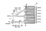
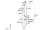
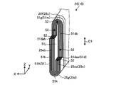
- FIG. 1 is a schematic and exemplary perspective view of a battery 10 of the present embodiment.
- FIG. 2 is a schematic and exemplary exploded perspective view of the battery 10 of the present embodiment.
- the battery 10 includes a housing 20, a positive electrode terminal 23, a negative electrode terminal 24, an electrode assembly 25, a positive electrode lead 26, and a negative electrode lead 27.
- the battery 10 is, for example, a lithium ion secondary battery.
- the positive electrode terminal 23 and the negative electrode terminal 24 are exposed to the outside of the housing 20 in a state of being supported by the housing 20.
- the electrode body 25, the positive electrode lead 26, and the negative electrode lead 27 are accommodated in the housing 20.
- the positive electrode terminal 23 and the negative electrode terminal 24 are examples of terminals.
- the positive electrode terminal 23 and the negative electrode terminal 24 are also referred to as electrode terminals.
- the housing 20 is configured in a flat rectangular shape that is thin in the X direction.
- the housing 20 has a plurality of wall portions 20a to 20f.
- Each of the wall portion 20a and the wall portion 20c extends along a direction intersecting with the thickness direction (X direction) of the housing 20 (in the present embodiment, for example, a direction orthogonal to the YZ plane).
- the wall 20 a and the wall 20 c are provided in parallel with each other at an interval in the thickness direction (X direction) of the housing 20.
- the wall portion 20b and the wall portion 20d both extend along a direction (for example, a direction orthogonal to the XZ plane in the present embodiment) intersecting with the width direction (Y direction) of the housing 20.
- the wall 20 b and the wall 20 d are provided in parallel with each other at an interval in the width direction (Y direction) of the housing 20.
- the walls 20a to 20d are also referred to as side walls or the like.
- the wall portions 20a and 20c are examples of the long side portion of the side wall portion, and the wall portions 20b and 20d are examples of the short side portion of the side wall portion.
- the wall 20 e and the wall 20 f both extend along a direction (for example, a direction orthogonal to the present embodiment, an XY plane) intersecting with the vertical direction (Z direction) of the housing 20.
- the wall 20 e and the wall 20 f are provided in parallel with each other at an interval in the vertical direction (Z direction) of the housing 20.
- the wall 20 e is also referred to as a lower wall, a bottom wall, or the like.
- the wall portion 20 f is also referred to as an upper wall portion, a ceiling wall portion, or the like.
- the housing 20 is also referred to as an outer can or a case.
- the housing 20 can be comprised combining a some components (divided body).
- the housing 20 includes the housing member 21 including at least the wall portions 20a to 20e, and the lid member 22 including at least the wall portion 20f.
- the accommodation member 21 is configured in a rectangular parallelepiped box shape whose one end side (upper end side) is open.
- the lid member 22 is formed in a rectangular (rectangular) plate shape, and is coupled (integrated) with the housing member 21 in a state where the opening of the housing member 21 is closed.
- the housing member 21 and the lid member 22 can be airtightly and fluidically coupled, for example, by welding or the like.
- the housing member 21 and the lid member 22 are made of, for example, a metal material (for example, aluminum, aluminum alloy, stainless steel, etc.).
- An insulating member may be provided on the inner surface of the wall portions 20a to 20e to insulate the housing member 21 from the container such as the positive electrode lead 26 and the negative electrode lead 27.
- the insulating member may be made of, for example, an insulating sheet or a molded product.
- the housing member 21 and the lid member 22 are also referred to as a housing member.
- the positive electrode terminal 23, the negative electrode terminal 24, the electrode assembly 25, the positive electrode lead 26, and the negative electrode lead 27 are attached to the lid member 22.
- the lid member 22 constitutes the lid assembly 11 together with the positive electrode terminal 23, the negative electrode terminal 24, the electrode body 25, the positive electrode lead 26, and the negative electrode lead 27.
- the positive electrode terminal 23 and the negative electrode terminal 24 are provided on the lid member 22 (wall 20f). Specifically, the positive electrode terminal 23 is provided at one end of the lid member 22 in the longitudinal direction (Y direction, width direction of the housing 20), and the negative electrode terminal 24 is disposed in the longitudinal direction (Y direction, housing of the lid member 22). It is provided at the other end of the body 20 in the width direction).
- the positive electrode terminal 23 is supported by the wall 20 f (the housing 20) in a state of penetrating the wall 20 f and is coupled to the positive electrode lead 26 inside the housing 20. That is, the positive electrode terminal 23 is electrically connected to the positive electrode lead 26.
- the negative electrode terminal 24 is supported by the wall 20 f (the housing 20) in a state of penetrating the wall 20 f and is coupled to the negative electrode lead 27 inside the wall 20 f (the housing 20). That is, the negative electrode terminal 24 is electrically connected to the negative electrode lead 27.
- seal members 28 are provided between the positive electrode terminal 23 and the wall portion 20 f and between the negative electrode terminal 24 and the wall portion 20 f, respectively.
- the seal member 28 is made of an insulator such as a synthetic resin material or glass.
- the seal member 28 seals (seals) air tight and liquid tight and electrically insulates between the positive electrode terminal 23 and the negative electrode terminal 24 and the wall portion 20 f.
- a liquid injection port (not shown) is provided in the wall portion 20 f between the positive electrode terminal 23 and the negative electrode terminal 24. An electrolyte is injected into the housing 20 from the injection port. The filling port is closed after filling.
- FIG. 3 is a schematic and exemplary exploded perspective view of the electrode body 25 of the battery 10 of the present embodiment, showing a state in which a part of the electrode body 25 is developed.
- the electrode body 25 has a sheet-like positive electrode 31, a sheet-like negative electrode 32, and a plurality of sheet-like separators 33.
- the electrode body 25 functions as a power generation element.
- the separators 33 are hatched for understanding.
- the positive electrode 31 and the negative electrode 32 are examples of a pair of electrodes having different polarities.
- the electrode body 25 is also referred to as an electrode group or a wound body.
- the electrode body 25 has a flat outer appearance in which the positive electrode 31 and the negative electrode 32 and the separator 33 interposed between the positive electrode 31 and the negative electrode 32 are stacked and wound on each other. That is, the positive electrode 31 and the negative electrode 32 are overlapped via the separator 33.
- the number of windings of the positive electrode 31, the negative electrode 32, and the separator 33 is 38, for example.
- the number of windings of the positive electrode 31, the negative electrode 32, and the separator 33 may be other than 38 times.
- the positive electrode 31 and the negative electrode 32 are separated by the separator 33.
- the positive electrode 31 is located between the two separators 33.
- the positive electrode 31, the negative electrode 32, and the separator 33 are spirally wound around the central axis Ax in a state of being stacked on one another, and pressed flatly, whereby the electrode body 25 is manufactured.
- the electrode body 25 is accommodated in the housing 20 in a posture in which the central axis Ax is along the width direction (Y direction) of the housing 20.
- the central axis Ax is also referred to as a center line or a winding center line.
- the electrode assembly 25 has both axial end portions 25a and 25b, and both end portions 25c and 25d of the first direction D1 intersecting (orthogonal to) the axial direction.
- the first direction D1 is along the vertical direction (Z direction) of the housing 20.
- the end 25 c is an end on one side (upper side) of the first direction D 1 of the electrode body 25, and the end 25 d is an end on the other side (lower side) of the first direction D 1 of the electrode body 25.
- the electrode body 25 has a base portion 25e and a pair of folded portions 25f and 25g.
- the base portion 25 e and the pair of folded portions 25 f and 25 g respectively include a positive electrode 31, a negative electrode 32, and a separator 33.
- the base 25e has a pair of extending portions 25ea and 25eb in which the positive electrode 31, the negative electrode 32, and the separator 33 extend in the first direction D1.
- the extension portions 25ea and 25eb are provided between both end portions 25c and 25d of the electrode body 25 in the first direction D1. Further, a central axis Ax is located between the extensions 25ea and 25eb.
- the positive electrode 31, the negative electrode 32, and the separator 33 extend in the first direction D1, and the positive electrode 31, the negative electrode 32, and the separator 33 are not folded back.
- the base portion 25e is also referred to as a straight portion or an intermediate portion, and the folded portions 25f and 25g are also referred to as an R portion.
- the pair of folded portions 25f, 25g are provided at both end portions 25c, 25d of the electrode body 25 in the first direction D1.
- the positive electrode 31, the negative electrode 32, and the separator 33 are folded back from one of the pair of extended portions 25ea and 25eb to the other. That is, the pair of folded back portions 25f, 25g is connected to both ends of the base portion 25e in the first direction D1.
- the pair of folded back portions 25f, 25g are connected by the base portion 25e. That is, the base portion 25e is interposed between the pair of folded portions 25f and 25g.
- the positive electrode 31 has a positive electrode current collector 41 and a positive electrode active material containing layer 42.
- the positive electrode active material-containing layer 42 is hatched for the sake of understanding.
- the positive electrode current collector 41 is an example of a current collector, and the positive electrode active material containing layer 42 is an example of an active material containing layer.
- the positive electrode current collector 41 is also referred to as a substrate, a sheet, or a conductor.
- the positive electrode current collector 41 is made of a metal foil such as an aluminum foil or an aluminum alloy. That is, the positive electrode current collector 41 contains aluminum.
- the positive electrode current collector 41 is formed in a substantially rectangular (square) sheet shape (stripe).
- the positive electrode current collector 41 may be made of another material, or may be formed in another shape.
- the positive electrode active material-containing layer 42 is provided on both sides (front and back) of the positive electrode current collector 41.
- the positive electrode active material-containing layer 42 may be provided only on one side of the positive electrode current collector 41.
- the positive electrode active material containing layer 42 partially covers both surfaces of the positive electrode current collector 41. That is, the positive electrode active material containing layer 42 is laminated on part of the positive electrode current collector 41.
- the length in the longitudinal direction of the positive electrode active material-containing layer 42 is substantially equal to the length in the longitudinal direction of the positive electrode current collector 41.
- the length (width) of the positive electrode active material-containing layer 42 in the lateral direction is shorter than the length (width) of the positive electrode current collector 41 in the lateral direction.
- the positive electrode current collector 41 has a positive electrode non-laminated portion 48A.
- the positive electrode non-laminated portion 48 ⁇ / b> A is configured by a portion of the positive electrode current collector 41 where the positive electrode active material-containing layer 42 is not stacked.
- the positive electrode non-laminated portion 48A is provided at one end of the strip-shaped positive electrode current collector 41 in the width direction. The other end of the positive electrode current collector 41 in the width direction is covered with the positive electrode active material-containing layer 42.
- the positive electrode non-laminated portion 48A extends in parallel with the positive electrode current collector 41 and the positive electrode active material containing layer 42.
- the positive electrode non-laminated portion 48A is an example of the non-laminated portion.
- the positive electrode non-laminated portion 48A is also referred to as an uncoated portion.
- the positive electrode active material containing layer 42 contains a positive electrode active material, a conductive agent, and a binder (binder).
- the positive electrode active material-containing layer 42 is obtained, for example, by suspending the positive electrode active material, the conductive agent, and the binder in a solvent, and applying the suspension (slurry) to the positive electrode current collector 41, drying, and pressing. It is formed.
- the positive electrode active material is, for example, various oxides or sulfides.
- the positive electrode active material is, for example, manganese dioxide (MnO 2 ), iron oxide, copper oxide, nickel oxide, lithium manganese composite oxide (for example, Li x Mn 2 O 4 or Li x MnO 2 ), lithium nickel composite oxide ( For example, Li x NiO 2), lithium cobalt composite oxide (Li x CoO 2), lithium nickel cobalt composite oxide (e.g., Li x Ni 1-y- z Co y M z O 2 .M is, Al, Cr And at least one element selected from the group consisting of Fe, 0 ⁇ y ⁇ 0.5, 0 ⁇ z ⁇ 0.1), lithium manganese cobalt composite oxide (eg, Li x Mn 1 -y-z) Co y M z O 2 .M is, Al, Cr, and at least one element .0 ⁇ y ⁇ 0.5,0 ⁇ z ⁇ 0.1), lithium
- the positive electrode active material may be a conductive polymer material such as polyaniline or polypyrrole, a disulfide-based polymer material, sulfur (S), and an organic material or an inorganic material such as carbon fluoride.
- a conductive polymer material such as polyaniline or polypyrrole
- S sulfur
- an organic material or an inorganic material such as carbon fluoride.
- it is preferable that it is a range of 0 or more and 1 or less x, y, and z which do not have description of a preferable range above.
- More preferable positive electrode active materials are, for example, lithium manganese composite oxide, lithium nickel composite oxide, lithium cobalt composite oxide, lithium nickel cobalt composite oxide, lithium manganese nickel composite compound, spinel lithium manganese nickel composite oxide, lithium It is a manganese cobalt composite oxide or lithium iron phosphate.
- the battery 10 having these positive electrode active materials can obtain a high voltage.
- the conductive agent is, for example, one or more of acetylene black, carbon black, graphite, coke, carbon fiber, graphene and the like.
- the binder for example, polytetrafluoroethylene (PTFE), polyvinylidene fluoride (PVDF), fluorine-based rubber, styrene butadiene rubber, ethylene-butadiene rubber (SBR), polypropylene (PP), polyethylene (PE), carboxymethyl cellulose ( CMC), polyimide (PI), polyacrylimide (PAI), modified PVDF in which at least one of hydrogen and fluorine of PVDF is substituted with another substituent, copolymer of vinylidene fluoride and 6-fluoro fluoride, polyfluorophenyl Mention may be made of vinylidene fluoride-tetrafluoroethylene-6 propylene propylene terpolymer and acrylic resins.
- the type of binder can be one type or two or more types.
- the negative electrode 32 has a negative electrode current collector 45 and a negative electrode active material containing layer 46.
- the negative electrode active material containing layer 46 is hatched for the sake of understanding.
- the negative electrode current collector 45 is an example of a current collector, and the negative electrode active material containing layer 46 is an example of an active material containing layer.
- the negative electrode current collector 45 is also referred to as a substrate, a sheet, or a conductor.
- the negative electrode current collector 45 is made of, for example, a metal foil such as copper foil, aluminum foil, or aluminum alloy foil. That is, when the negative electrode current collector 45 is made of aluminum foil or aluminum alloy foil, it contains aluminum.
- the negative electrode current collector 45 is formed in a substantially rectangular (square) sheet shape (stripe).
- the negative electrode current collector 45 may be made of another material, or may be formed in another shape.
- the negative electrode active material containing layer 46 is provided on both sides of the negative electrode current collector 45. That is, the negative electrode active material containing layer 46 is laminated on part of the negative electrode current collector 45.
- the negative electrode active material containing layer 46 may be provided only on one side of the negative electrode current collector 45. However, the negative electrode active material containing layer 46 is provided on the surface facing the positive electrode active material containing layer 42.
- the negative electrode active material containing layer 46 partially covers the surface of the negative electrode current collector 45. That is, the negative electrode active material containing layer 46 is laminated on part of the negative electrode current collector 45.
- the length in the longitudinal direction of the negative electrode active material-containing layer 46 is substantially equal to the length in the longitudinal direction of the negative electrode current collector 45.
- the length (width) in the short direction of the negative electrode active material-containing layer 46 is shorter than the length (width) in the short direction of the negative electrode current collector 45.
- the negative electrode current collector 45 has a negative electrode non-laminated portion 48B.
- the negative electrode non-laminated portion 48 B is configured by a portion of the negative electrode current collector 45 where the negative electrode active material containing layer 46 is not stacked.
- the negative electrode non-laminated portion 48 B is provided at one end in the width direction of the strip-shaped negative electrode current collector 45. The other end of the negative electrode current collector 45 in the width direction is covered with the negative electrode active material containing layer 46.
- the negative electrode non-laminated portion 48 B extends in parallel to the negative electrode current collector 45 and the negative electrode active material containing layer 46.
- the negative electrode non-laminated portion 48B is an example of the non-laminated portion.
- the negative electrode non-laminated portion 48B is also referred to as an uncoated portion.
- the negative electrode active material containing layer 46 contains a negative electrode active material, a conductive agent, and a binder (binder).
- the negative electrode active material-containing layer 46 is made by suspending a powdery negative electrode active material, a conductive agent, and a binder in a solvent, and applying the suspension (slurry) to the negative electrode current collector 45, drying, and pressing It is formed by doing. A press is performed to increase the electrical contact between the negative electrode active material and the negative electrode current collector 45.
- the negative electrode active material is not particularly limited.
- the negative electrode active material is, for example, lithium titanium composite oxide (lithium titanate).
- the lithium titanium composite oxide is, for example, a spinel type lithium titanate represented by Li 4 + x Ti 5 O 12 (x changes in a range of ⁇ 1 ⁇ x ⁇ 3 by charge and discharge reaction), a ramsteride type Li 2 + x Ti.
- this metal complex oxide has a low crystallinity and a microstructure in which a crystalline phase and an amorphous phase coexist or exist alone in the amorphous phase.
- a microstructure metal complex oxide can significantly improve the cycle performance.
- These metal complex oxides are converted to lithium titanium complex oxides by the insertion of lithium upon charging.
- spinel-type lithium titanate is preferable because it has excellent cycle characteristics.
- the lithium-titanium composite oxide eg, spinel type lithium titanate
- the negative electrode active material containing layer 46 may contain, for example, a graphitic material, a carbonaceous material or a metal compound as another negative electrode active material.
- the graphite material is, for example, graphite (natural graphite, artificial graphite).
- the carbonaceous material is, for example, coke, carbon fiber (vapor-grown carbon fiber, mesophase pitch-based carbon fiber), spherical carbon, pyrolytic gas-phase carbonaceous material, or resin-fired carbon. More preferred carbonaceous materials are vapor grown carbon fibers, mesophase pitch based carbon fibers, and spherical carbon.
- the metal compound is, for example, metal sulfide or metal nitride.
- the metal sulfide is, for example, titanium sulfide such as TiS 2 , molybdenum sulfide such as MoS 2 , or iron sulfide such as FeS, FeS 2 and Li x FeS 2 .
- Metal nitrides are, for example, lithium cobalt nitride (e.g. Li s Co t N, 0 ⁇ s ⁇ 4,0 ⁇ t ⁇ 0.5).
- the negative electrode active material may be a chalcogen compound (eg, titanium disulfide, molybdenum disulfide, niobium selenide, etc.) or a light metal (eg, aluminum, aluminum alloy, magnesium alloy, lithium, lithium alloy, etc.) .
- chalcogen compound eg, titanium disulfide, molybdenum disulfide, niobium selenide, etc.
- a light metal eg, aluminum, aluminum alloy, magnesium alloy, lithium, lithium alloy, etc.
- the conductive agent is, for example, one or more of acetylene black, carbon black, graphite, coke, carbon fiber, graphene and the like.
- the binder for example, polytetrafluoroethylene (PTFE), polyvinylidene fluoride (PVDF), fluorine-based rubber, styrene butadiene rubber, ethylene-butadiene rubber (SBR), polypropylene (PP), polyethylene (PE), carboxymethyl cellulose ( CMC), polyimide (PI), polyacrylimide (PAI), modified PVDF in which at least one of hydrogen and fluorine of PVDF is substituted with another substituent, copolymer of vinylidene fluoride and 6-fluoro fluoride, polyfluorophenyl Mention may be made of vinylidene fluoride-tetrafluoroethylene-6 propylene propylene terpolymer and acrylic resins.
- the type of binder can be one type or two or more types.
- the positive electrode non-stacked portion 48A and the negative electrode non-stacked portion 48B protrude in the opposite direction to each other. That is, the positive electrode non-laminated portion 48A protrudes from one end of the positive electrode 31, the negative electrode 32, and the separator 33 which are stacked and wound on one another in the axial direction (Y direction), and the negative electrode non-laminate from the other end.
- the stacked portion 48B protrudes on the other side in the axial direction (opposite to the Y direction). That is, the positive electrode 31 and the negative electrode 32 are mutually offset and overlapped.
- the non-laminated portion 48 may be used as a generic term for the positive electrode non-laminated portion 48A and the negative electrode non-laminated portion 48B.
- a flat power generation unit 50 is configured by the overlapping portions of the positive electrode 31, the negative electrode 32, and the separator 33 in a wound state.
- the positive electrode non-laminated portion 48A in a wound state constitutes a positive electrode current collector 51A extending from one end of the power generation unit 50. That is, the positive electrode current collecting portion 51A includes a portion (positive electrode non-laminated portion 48A) in which the positive electrode active material-containing layer 42 is not stacked in the positive electrode current collector 41.
- the positive electrode current collector 51A is configured by the positive electrode 31.
- the axial end 25a of the electrode body 25 is also an end of the positive electrode current collector 41 and the positive electrode non-laminated portion 48A.
- the positive electrode current collector 51A is electrically connected to the positive electrode terminal 23.
- the positive electrode current collector 51A is an example of a current collector.
- the negative electrode non-laminated portion 48B in a wound state forms a negative electrode current collector 51B extending from the other end of the power generation unit 50. That is, the negative electrode current collecting portion 51B includes a portion (negative electrode non-laminated portion 48B) in which the negative electrode active material containing layer 46 is not stacked in the negative electrode current collector 45. As understood from the above, the negative electrode current collector 51B is configured by the negative electrode 32. The axial end 25 b of the electrode body 25 is also an end of the negative electrode current collector 45 and the negative electrode non-laminated portion 48 B. The negative electrode current collector 51B is electrically connected to the negative electrode terminal 24.
- the current collection unit 51 may be used as a generic name of the positive electrode current collection unit 51A and the negative electrode current collection unit 51B.
- the negative electrode current collector 51B is an example of a current collector.
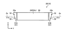
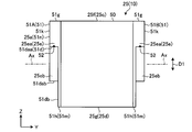
- FIG. 4 is a schematic and exemplary view of the current collection unit 51 of the electrode body 25 according to the present embodiment, as viewed from the axial direction.
- the positive electrode current collection unit 51 ⁇ / b> A includes a plurality of current collection tabs 51 ⁇ / b> Aa stacked one on another.
- the plurality of current collection tabs 51Aa are a part of the positive electrode non-stacked portion 48A, that is, a part of the positive electrode 31, and are stacked on each other without the negative electrode 32 and the separator 33 being other electrodes.
- the boundaries between the current collection tabs 51Aa may be provided, for example, at both ends of the positive electrode current collection unit 51A in the first direction D1.
- FIG. 1 In FIG.
- the boundary between the current collection tabs 51Aa is indicated by a solid line L1.
- the position of the boundary portion is not limited to this, and may be any position.
- the positive electrode current collection unit 51A and the negative electrode current collection unit 51B are illustrated without being distinguished for describing the same configuration included in the positive electrode current collection unit 51A and the negative electrode current collection unit 51B.
- the negative electrode current collection unit 51B includes a plurality of current collection tabs 51Ba stacked on one another.
- the current collection tab 51Ba is a part of the negative electrode non-laminated portion 48B, that is, a part of the negative electrode 32, and is stacked on each other without the positive electrode 31 and the separator 33 which are other electrodes.
- boundary portions between the current collection tabs 51Ba may be provided, for example, at both ends of the negative electrode current collection unit 51B in the first direction D1.
- the boundary between the current collection tabs 51 ⁇ / b> Ba is indicated by a solid line L ⁇ b> 2.
- the position of the boundary portion is not limited to this, and may be any position.
- the current collection tab 51a may be used as a generic term for the current collection tab 51Aa of the positive electrode current collection unit 51A and the current collection tab 51Ba of the negative electrode current collection unit 51B.
- the edge 51 b of the current collection tab 51 a is provided at the end 25 a or 25 b opposite to the power generation unit 50 of the current collection unit 51 and exposed. ing.
- the plurality of current collection tabs 51 a stacked on each other in each current collection unit 51 have their respective edge portions 51 b aligned.
- the positions of the edge portions 51b of the plurality of current collection tabs 51a overlapped with each other are aligned in the axial direction. That is, the edge portions 51b of the plurality of current collection tabs 51a overlapped with each other are located at the same position in the axial direction.
- the edges 51 b of the plurality of current collection tabs 51 a stacked on one another are located on a predetermined plane that intersects (orthogonal) with the axial direction.
- Each current collection unit 51 is provided with a cutting unit 51 d.
- the cutting portion 51 d is provided at both end portions 51 g and 51 h of the current collecting portion 51 in the first direction D1 at the end portions 25 a and 25 b opposite to the power generation portion 50 of the current collecting portion 51.
- the cutting unit 51 d includes an edge 51 b of the current collection tab 51 a. That is, the cutting unit 51d constitutes the end 25a, 25b of the current collecting unit 51 opposite to the power generation unit 50 and the edge 51b of the current collecting tab 51a.
- the cutting portion 51 d is formed by melting and cutting off the removing portion 60 c (FIG. 8) from the current collecting portion 51 in the base 60 (FIG. 8) of the electrode body 25 at the time of manufacturing the electrode body 25. is there.
- the cutting portion 51 d is also referred to as a cutting portion or a cutting surface.
- FIG. 5 is a schematic and exemplary cross-sectional view of a portion of the electrode body 25 of the present embodiment.
- each current collection unit 51 is provided with a junction 52.
- the gap S between two adjacent current collection tabs 51a is exaggerated for the sake of understanding.
- the joint portion 52 joins the edge portions 51 b of the plurality of current collection tabs 51 a stacked on each other in the current collection unit 51.
- the bonding portion 52 is formed by solidification of the edge portion 51b after melting when the removal portion 60c (FIG. 8) is fused to the current collecting portion 51 in the base material 60 (FIG. 8). .
- the joint portion 52 is provided in the cutting portion 51d, and constitutes the edge portion 51b.
- the bonding portion 52 partially bonds the edges 51 b of the plurality of current collecting tabs 51 a stacked on one another.
- the plurality of bonding portions 52 are provided separately from one another. That is, in each current collection unit 51, a plurality of junctions 52 are provided in a distributed manner.
- the number and positions of the joint portions 52 shown in FIGS. 2, 4 and 5 are merely examples, and the present invention is not limited thereto. Further, the joint 52 may be one.
- FIG. 6 is a schematic and exemplary cross-sectional view of part of the current collection unit 51 of the present embodiment.
- FIG. 7 is a schematic and exemplary cross-sectional view of part of the current collection unit 51 of the present embodiment.
- each non-stacked portion 48 has a first portion 48a and a second portion 48b.
- the 1st part 48a and the 2nd part 48b of positive electrode non-laminated part 48A are shown.
- the first portion 48 a extends from the positive electrode active material containing layer 42 or the negative electrode active material containing layer 46.
- the first portion 48a constitutes a part of the current collection tab 51a.
- the second portion 48 b is connected to the first portion 48 a and constitutes the other portion of the current collection tab 51 a.
- the second portion 48b includes an edge 51b, a thickness change portion 48c, and a thick portion 48d.
- the thickness change portion 48c becomes thicker as it goes away from the first portion 48a.
- the thick portion 48 d is the portion with the largest thickness in the non-laminated portion 48 and is also the portion with the largest thickness in the current collection tab 51 a.
- the thickness of the thick portion 48d is, for example, 1.2 or more times the thickness (maximum thickness) of the first portion 48a. 5 and 6, the thickness of the thick portion 48d is indicated by the thickness T1, and the thickness (maximum thickness) of the first portion 48a is indicated by the thickness T2. In the example of FIG. 6, for example, the thickness T1 of the thick portion 48d is 67 ⁇ m, and the thickness T2 of the first portion 48a is 20 ⁇ m.
- FIG. 7 shows a current collection tab 51a different from the current collection tab 51a provided in the non-stacked portion 48 shown in FIG. In the example of FIG. 7, for example, the thickness T1 of the thick portion 48d is 20 ⁇ m, and the thickness T2 of the first portion 48a is 13 ⁇ m.
- the thickness T1 of the thick portion 48d and the thickness T2 of the first portion 48a are not limited to the above examples.
- the first portion 48a is also referred to as a thin portion.
- the positive electrode current collecting portion 51A as an example, portions of the positive electrode non-laminated portions 48A overlapping each other in the X direction are overlapped with the leg portion 26a of the positive electrode lead 26 in the X direction. The parts are joined together by ultrasonic bonding or the like. Then, the width in the X direction of at least the tip of the positive electrode current collector 51A is narrower than the width in the X direction of the electrode assembly 25 (FIG. 2).
- the portions of the negative electrode non-laminated portions 48B overlapping each other in the X direction and portions overlapping the leg 27a of the negative electrode lead 27 in the X direction Are joined by
- the width in the X direction of at least the tip of the negative electrode current collector 51B is narrower than the width in the X direction of the electrode assembly 25 (FIG. 2).
- FIG. 3 portions of the positive electrode non-laminated portions 48A overlapping in the X direction and portions of the negative electrode non-laminated portion 48B overlapping in the X direction are shown before being joined to each other. It is done.
- the separator 33 shown in FIG. 3 and the like has an insulating property and is formed in a substantially rectangular (square) sheet shape (strip).
- the length (width) of the separator 33 in the short direction is shorter than the length (width) of the positive electrode current collector 41 and the negative electrode current collector 45 in the short direction.
- the dimensions of the separator 33 are not limited to this.
- the separator 33 is, for example, a porous film made of a polyolefin such as polyethylene or polypropylene, cellulose, polyethylene terephthalate, polyester, polyvinyl alcohol, polyimide, polyamide, polyamide imide, polytetrafluoroethylene, vinylon or the like, or non-woven fabric It is. Examples of preferred separators in terms of thinness and mechanical strength include nonwoven fabrics containing cellulose fibers.
- the separator 33 may be made of one type of material, or may be made of two or more types of combined materials.
- a non-aqueous electrolyte can be used as the electrolytic solution.
- the non-aqueous electrolyte may be, for example, a liquid non-aqueous electrolyte prepared by dissolving the electrolyte in an organic solvent, or a gel non-aqueous electrolyte in which a liquid electrolyte and a polymer material are complexed.
- the liquid non-aqueous electrolyte is preferably one in which the electrolyte is dissolved in an organic solvent at a concentration of 0.5 mol / L to 2.5 mol / L.
- Examples of the electrolyte to be dissolved in an organic solvent include lithium perchlorate (LiClO 4 ), lithium hexafluorophosphate (LiPF 6 ), lithium tetrafluoroborate (LiBF 4 ), lithium hexafluoride arsenic (LiAsF 6) And lithium salts such as lithium trifluoromethanesulfonate (LiCF 3 SO 3 ), and bistrifluoromethylsulfonylimide lithium (LiN (CF 3 SO 2 ) 2 ), and mixtures thereof. It is preferable that the electrolyte be resistant to oxidation even at high potential, and LiPF 6 is most preferable.
- organic solvents examples include cyclic carbonates such as propylene carbonate (PC), ethylene carbonate (EC) and vinylene carbonate and diethyl carbonate (DEC), dimethyl carbonate (DMC) and ethyl methyl carbonate (EMC).
- PC propylene carbonate
- EC ethylene carbonate
- DEC vinylene carbonate and diethyl carbonate
- DMC dimethyl carbonate
- EMC ethyl methyl carbonate
- Cyclic carbonates and cyclic ethers such as tetrahydrofuran (THF), 2-methyltetrahydrofuran (2-MeTHF), and dioxolane (DOX), and linear chains such as dimethoxyethane (DME) and diethoxyethane (DEE) Ethers, propionate esters such as methyl propionate (MP) and ethyl propionate (EP), ⁇ -butyrolactone (GBL), acetonitrile (AN) and sulfolane (SL) are included. These organic solvents can be used alone or as a mixed solvent.
- the positive electrode lead 26 is interposed between the positive electrode current collector portion 51A of the electrode body 25 and the positive electrode terminal 23, and the positive electrode current collector portion 51A and the positive electrode terminal 23 are electrically connected. There is.
- the positive electrode lead 26 has a pair of legs 26 a and a connection wall (not shown).
- the pair of leg portions 26 a extends in the vertical direction (Z direction) of the housing 20 and is provided at an interval from each other in the thickness direction (X direction) of the housing 20.
- the pair of leg portions 26a is joined to the positive electrode current collector 51A with the positive electrode current collector 51A interposed therebetween.
- the some laminated current collection tab 51a is mutually joined.
- the joining of the pair of leg portions 26a and the positive electrode current collecting portion 51A and the joining of the stacked plurality of current collecting tabs 51a are performed by, for example, ultrasonic bonding or the like.
- the ends on the lid member 22 (wall 20f) side of the pair of legs 26a are connected to each other by a connection wall.
- the connection wall portion is provided along the inner surface of the lid member 22 and is coupled to the positive electrode terminal 23.
- the positive electrode lead 26 is made of a conductive material such as a metal material.
- the negative electrode lead 27 is interposed between the negative electrode current collector 51B of the electrode body 25 and the negative electrode terminal 24, and electrically connects the negative electrode current collector 51B to the negative electrode terminal 24.
- the negative electrode lead 27 has a pair of legs 27 a and a connection wall (not shown).
- the pair of legs 27 a extends in the vertical direction (Z direction) of the housing 20 and is provided at an interval in the thickness direction (X direction) of the housing 20.
- the pair of leg portions 27a is joined to the negative electrode current collector 51B with the negative electrode current collector 51B interposed therebetween.
- the joining of the pair of leg portions 27a and the negative electrode current collecting portion 51B and the joining of the stacked plurality of current collecting tabs 51a are performed by, for example, ultrasonic bonding or the like.
- the ends on the lid member 22 (wall 20f) side of the pair of legs 27a are connected to each other by a connection wall.
- the connection wall portion is provided along the inner surface of the lid member 22 and is coupled to the negative electrode terminal 24.
- the negative electrode lead 27 is made of a conductive material such as a metal material.
- FIG. 8 is a schematic and exemplary perspective view of the electrode assembly 25 in the process of the present embodiment.
- FIG. 9 is a schematic and exemplary front view of the electrode assembly 25 in the process of the present embodiment.
- FIG. 10 is a schematic and exemplary plan view of the electrode assembly 25 in the process of the present embodiment.
- FIG. 11 is a schematic and exemplary side view of the electrode assembly 25 in the process of the present embodiment.
- the positive electrode 31 and the negative electrode 32, and the separator 33 interposed between the positive electrode 31 and the negative electrode 32 are stacked on one another and wound around the central axis Ax, thereby including the electrode assembly 25.
- the base material 60 is produced.
- the removal part 60c which is a predetermined part of the axial direction both ends 60a and 60b of the base material 60 is cut
- the cutting part 51d is formed by this cutting.
- the boundary line L3 between the electrode body 25 and the removing portion 60c is indicated by an alternate long and short dash line.
- the cutting of the substrate 60 is performed by cutting (melting) the heat collection portion 51 (positive electrode non-laminated portion 48A, negative electrode non-laminated portion 48B) by heat.
- the laser light from the laser irradiation device as the cutting device is applied to the current collector 51 (positive electrode non-laminated portion 48A and negative electrode non-laminated portion 48B) along the boundary L3.
- the current collector 51 (the positive electrode non-laminated portion 48A and the negative electrode non-laminated portion 48B) is heated and fused.
- the bonding portion 52 (FIGS. 2, 4 and 5) is formed in the cutting portion 51 d of the current collecting portion 51. That is, in the present embodiment, the bonding portion 52 is formed by solidifying the plurality of current collecting tabs 51 a stacked on each other in the current collecting portion 51 by laser light.
- the above laser beam may be, for example, a single mode fiber laser or a multimode fiber laser.
- the single mode fiber laser is characterized in that the diameter of the laser beam is relatively small and the energy density is high, so that the plurality of current collecting tabs 51a stacked one on another can be efficiently cut at any position.
- the diameter of the laser light that is, the cutting width becomes relatively thin, and the size of each junction 52 becomes relatively small.
- the diameter of the laser light, that is, the cutting width becomes relatively large, and the size of each bonding portion 52 becomes relatively large.
- the irradiation of the laser light may be divided and performed a plurality of times. In this case, the output of the laser irradiation apparatus per one time can be reduced. For this reason, energy loss can be made small, and the influence of the heat added to the cutting part 51d can be made small.
- the cutting of the substrate 60 is not limited to the cutting by laser light.
- the cutting of the substrate 60 may be performed by ultrasonic cutting or the like.
- the cutting device may have a pressing device capable of pressing the end portions 60 a and 60 b of the base material 60 including the current collecting portion 51 of the electrode body 25.
- the distance between the current collection tabs 51a is reduced and the gap between the current collection tabs 51a is reduced, so that the laser light is easily focused.
- the current collecting tabs 51a are easily melted.
- the tact time of cutting is likely to be shortened.
- the positive electrode current collecting portion 51A and the negative electrode current collecting portion 51B and the positive electrode lead 26 and the negative electrode lead 27 coupled to the lid member 22 are joined by ultrasonic bonding.
- the positive electrode current collection part 51A and the negative electrode current collection part 51B are pinched by the horn and the anvil of an ultrasonic bonding machine with the positive electrode lead 26 and the negative electrode lead 27, and thickness becomes thin partially.
- the positive electrode lead 26, the negative electrode lead 27, and the electrode body 25 in a state of being integrated with the lid member 22 are inserted into the housing member 21.
- the lid member 22 is coupled to the housing member 21 in a state in which the opening (upper end opening) of the housing member 21 is closed.
- an electrolytic solution is injected into the housing 20 by a predetermined amount through the liquid inlet of the lid member 22.
- the predetermined amount is, for example, an amount by which the electrode body 25 in the housing 20 is sufficiently immersed in the electrolytic solution.
- the liquid injection port is sealed.
- a polishing process is performed to polish the surface (outer surface) of the non-laminated portion 48 including the edge 51 b (cut portion 51 d).
- the processed layer on the surface is removed by a chemical polishing method such as ion milling.
- the surface of the non-laminated portion 48 is mechanically polished, the surface may be subjected to a chemical treatment with an aqueous solution of sodium hydroxide or the like.
- a scanning electron microscope is used, and imaging of the non-laminated portion 48 is performed at an observation magnification of 500 times or the like. And the thickness of each part of the non-laminated part 48 is measured from an imaging result.
- the observation magnification is not limited to the above.
- the edge portions 51 b of the plurality of current collection tabs 51 a stacked on each other in the current collection unit 51 of the electrode body 25 are joined by the joining unit 52.
- the plurality of current collection tabs 51 a stacked on each other in the current collection unit 51 are unlikely to be shifted. Therefore, deformation of the current collector 51 and hence the electrode body 25 is easily suppressed. Therefore, the strength and rigidity of the current collector 51 and the electrode body 25 can be increased compared to a configuration in which the edge 51 b of the current collector tab 51 a of the current collector 51 is not joined. Vibration resistance of the electrode body 25 is improved.
- the bonding portion 52 partially bonds the edges 51 b of the plurality of current collection tabs 51 a stacked on each other in the current collection unit 51.
- the gas generated between the positive electrode active material containing layer 42 and the negative electrode active material containing layer 46 in the electrode body 25 is joined to each other at the plurality of current collecting tabs 51Aa stacked one on another. It can discharge
- a thick portion 48 d which is the thickest portion of the non-laminated portion 48 is provided at the edge 51 b of the current collection tab 51 a of the current collection portion 51. According to such a configuration, since the thick portion 48d has a relatively high strength, the strength of the edge 51b can be increased. Thus, the vibration resistance of the current collector 51 and the electrode body 25 is improved.
- the battery 10 of the second to sixteenth embodiments has the same configuration as the battery 10 of the first embodiment. Therefore, the second to sixteenth embodiments can also achieve the same effects based on the same configuration as the first embodiment.
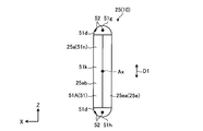
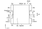
- FIG. 12 is a schematic and exemplary plan view of the electrode body 25 of the battery 10 of the present embodiment. As shown in FIG. 12, the present embodiment mainly differs from the first embodiment in the shape of the current collector 51.
- the cut portions 51 d of the end portions 25 a and 25 b of the current collection portion 51 are formed in a concave shape recessed toward the axial center of the electrode body 25.
- the cutting portion 51 d is configured in, for example, a substantially V shape when viewed from the Z direction.
- a recess 51j facing the cutting portion 51d is formed by the cutting portion 51d.
- the recess 51 j is recessed toward the axial center of the electrode body 25 (current collecting portion 51) and is formed in a groove shape extending across the both ends 25 c and 25 d of the electrode body 25.
- the recess 51 j is also referred to as a notch, a recess, a groove, or a missing portion.
- a bonding portion 52 is provided as in the first embodiment.
- the joint portion 52 faces the recess 51 j.
- the recessed portion 51 j is provided in the current collection unit 51, and the bonding portion 52 is provided in the cutting portion 51 d and faces the recessed portion 51 j. According to such a configuration, since the strength of the cut portion 51d is improved by the joint portion 52, deformation of the cut portion 51d is suppressed even when stress concentration occurs in the cut portion 51d by the recess 51j.
- FIG. 13 is a schematic and exemplary plan view of the electrode body 25 of the battery 10 of the present embodiment. As shown in FIG. 13, in the present embodiment, the shape of the current collector 51 is mainly different from that of the first embodiment.
- the cutting portion 51d of the end portions 25a and 25b of the current collecting portion 51 is inclined with respect to the central axis Ax.
- the cutting part 51d is separated from the axial center of the electrode assembly 25 as it goes from the wall 20a (FIG. 2) to the wall 20c (FIG. 2) of the housing 20, that is, as it goes to the X direction.
- a bonding portion 52 is provided as in the first embodiment.
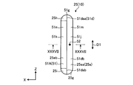
- FIG. 14 is a schematic and exemplary front view of the electrode body 25 of the battery 10 of the present embodiment.
- FIG. 15 is a schematic and exemplary side view of the electrode body 25 of the battery 10 of the present embodiment.
- the shape of the current collector 51 is mainly different from that of the first embodiment.
- one cutting part 51d is provided over the end 25a in the axial direction of the positive electrode current collector 51A and the one end 51g of the positive electrode current collector 51A in the first direction D1. Further, one cutting portion 51d is provided across the end 25a of the positive electrode current collector 51A and the other end 51h of the positive electrode current collector 51A in the first direction D1. Further, one cutting portion 51d is provided across the end 25b in the axial direction of the negative electrode current collector 51B and the one end 51g of the negative electrode current collector 51B in the first direction D1.
- one cutting portion 51d is provided along the axial end portion 25b of the negative electrode current collector 51B and the other end 51h of the negative electrode current collector 51B in the first direction D1.
- the cutting portion 51 d is provided at least one (both as an example) of both end portions 51 g and 51 h of the current collecting portion 51 in the first direction D1.
- the cutting portion 51d is inclined with respect to the central axis Ax.
- the cutting portion 51d is a central axis Ax so as to be separated from the central axis Ax as it goes from the straight portion 51k extending in the first direction D1 at the end portions 25a, 25b toward the central portion in the axial direction of the electrode body 25. It is inclined against. Further, in the cutting portion 51d, a bonding portion 52 is provided as in the first embodiment.
- the current collection part 51 has the base part 51m and the connection part 51n.
- the base portion 51m is a portion of the current collecting portion 51 axially extending from the power generation portion 50 by a predetermined length, and a portion of the base portion 25e and a portion of the pair of folded portions 25f and 25g It contains.
- the connection portion 51 n protrudes in the axial direction from the base portion 51 m.
- the connection portion 51 n includes a part of the base portion 25 e and the straight portion 51 k.
- Cutting portions 51 d are provided on both sides of the connection portion 51 n in the first direction D1.
- connection portion 51n having such a configuration includes a part of the pair of extending parts 25ea and 25eb, specifically, a part of each of the pair of extending parts 25ea and 25eb, and a part of the pair of folded parts 25f and 25g, Specifically, it includes a part of each of the pair of folded portions 25f, 25g.
- the connection portion 51 n of the positive electrode current collection unit 51 A is joined to the positive electrode lead 26 and electrically connected to the positive electrode terminal 23 via the positive electrode lead 26.
- the connection portion 51 n of the negative electrode current collecting portion 51 B is joined to the negative electrode lead 27 and electrically connected to the negative electrode terminal 24 via the negative electrode lead 27.
- an example of the boundary between the base portion 51 m and the connection portion 51 n is indicated by an alternate long and short dash line.
- the connection portion 51 n is also referred to as a protrusion or a protrusion.
- FIG. 16 is a schematic and exemplary front view of the electrode body 25 of the battery 10 of the present embodiment.
- FIG. 17 is a schematic and exemplary side view of the electrode body 25 of the battery 10 of the present embodiment.
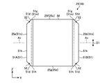
- four cutting portions 51 d are provided at each of the four corners of the electrode body 25.
- the cutting portion 51d includes a first extending portion 51da extending in the axial direction and a second extending portion 51db extending in the first direction D1.
- the connecting portion 51dc between the first extending portion 51da and the second extending portion 51db is formed in a curved shape.
- the connection portion 51dc is also referred to as a corner.
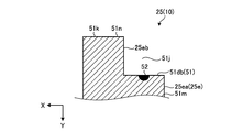
- the recessed portion 51 j facing the cutting portion 51 d is recessed toward the central portion in the axial direction of the electrode body 25 with respect to the straight portion 51 k. It can be said that the recess 51 j is recessed toward the axial center of the central axis Ax of the electrode body 25 and the center of the first direction D1. Further, a joint portion 52 is provided in the cutting portion 51 d. The joint portion 52 is provided in any one or more of the first extension portion 51da, the second extension portion 51db, and the connection portion 51dc. The joint portion 52 faces the recess 51 j.
- the current collection part 51 has the base part 51m and the connection part 51n.
- the base portion 51m is a portion of the current collecting portion 51 axially extended from the power generation portion 50 by a predetermined length, and a portion of the base portion 25e and a portion of the pair of folded portions 25f and 25g are cut.
- a second extending portion 51db of the portion 51d is configured by the exposed portion of the end portion where the connection portion 51n of the base portion 51m is provided.
- the connection portion 51 n protrudes in the axial direction from the base portion 51 m.
- the connection portion 51n includes a part of the base portion 25e, a straight portion 51k, and a first extension portion 51da of the cutting portion 51d.
- the end of the connecting portion 51 n in the first direction D1 constitutes a first extending portion 51 da.
- Cutting portions 51 d are provided on both sides of the connection portion 51 n in the first direction D1.
- the connecting portion 51n having such a configuration includes a part of the pair of extending parts 25ea and 25eb, specifically, a part of each of the pair of extending parts 25ea and 25eb, and at least the pair of folded parts 25f and 25g On the other hand, it does not specifically include both. That is, in the connection portion 51n, the positive electrode 31, the negative electrode 32, and the separator 33 are not folded back.
- an example of the boundary between the base portion 51 m and the connection portion 51 n is indicated by an alternate long and short dash line.
- FIG. 18 is a schematic and exemplary front view of the electrode body 25 of the battery 10 of the sixth embodiment.
- FIG. 19 is a schematic and exemplary side view of the electrode body 25 of the battery 10 of the sixth embodiment.
- each cutting portion 51 d is a first extension. It has a portion 51da and a second extending portion 51db.
- the connection portion 51dc between the first extending portion 51da and the second extending portion 51db is formed substantially at right angles.
- FIG. 20 is a schematic and exemplary front view of the electrode body 25 of the battery 10 of the present embodiment.
- FIG. 21 is a schematic and exemplary side view of the electrode body 25 of the battery 10 of the present embodiment.
- the shape of the current collector 51 is mainly different from that of the first embodiment.
- two cut portions 51 d are provided at two of four corners of the electrode body 25.
- one cutting part 51d is provided over the end 25a in the axial direction of the positive electrode current collector 51A and the one end 51g of the positive electrode current collector 51A in the first direction D1.
- one cutting portion 51d is provided across the end 25b in the axial direction of the negative electrode current collector 51B and the one end 51g of the negative electrode current collector 51B in the first direction D1.
- the cutting portion 51 d is provided on at least one (one as an example) of the both end portions 51 g and 51 h of the current collecting portion 51 in the first direction D1.
- the shape of each cutting portion 51d is, for example, the same as that of the sixth embodiment shown in FIG.
- the shape of each cutting portion 51d may be the shape of the fourth embodiment shown in FIG. 14 or the fifth embodiment shown in FIG.
- connection portion 51n of the current collection unit 51 of the present embodiment includes a part of each of the pair of extended portions 25ea and 25eb and a part of the folded portion 25g, and does not include the folded portion 25f.
- FIG. 22 is a schematic and exemplary front view of the electrode body 25 of the battery 10 of the present embodiment.
- FIG. 23 is a schematic and exemplary side view of the electrode body 25 of the battery 10 of the present embodiment.
- the shape of the current collector 51 is mainly different from that of the first embodiment.
- two cut portions 51 d are provided at two of four corners of the electrode body 25.
- one cutting portion 51d is provided across the end 25a of the positive electrode current collector 51A and the other end 51h of the positive electrode current collector 51A in the first direction D1.
- one cutting portion 51d is provided along the axial end portion 25b of the negative electrode current collector 51B and the other end 51h of the negative electrode current collector 51B in the first direction D1.
- the cutting portion 51 d is provided on at least one (one as an example) of the both end portions 51 g and 51 h of the current collecting portion 51 in the first direction D1.
- the shape of each cutting portion 51d is, for example, the same as that of the sixth embodiment shown in FIG.
- the shape of each cutting portion 51d may be the shape of the fourth embodiment shown in FIG. 14 or the fifth embodiment shown in FIG.
- connection portion 51n of the current collection unit 51 of the present embodiment includes a part of each of the pair of extended portions 25ea and 25eb and a part of the folded portion 25f, and does not include the folded portion 25g.
- FIG. 24 is a schematic and exemplary front view of the electrode body 25 of the battery 10 of the present embodiment.
- FIG. 25 is a schematic and exemplary side view of the electrode body 25 of the battery 10 of the present embodiment.
- FIG. 26 is a schematic and exemplary perspective view of the electrode body 25 of the battery 10 of the present embodiment.
- the shape of the current collector 51 is mainly different from that of the first embodiment.
- the current collector 51 includes a base 51 m and a connection 51 n as in the fifth embodiment.
- the connection portion 51 n of the present embodiment includes a portion of the folded portion 25 g in addition to a portion of the base portion 25 e and the straight portion 51 k.
- the lengths in the first direction D1 of the pair of extending portions 25ea, 25eb of the base portion 25e included in the connection portion 51n are different from each other.
- the length in the first direction D1 of the extending portion 25ea included in the connecting portion 51n is shorter than the length in the first direction D1 of the extending portion 25eb included in the connecting portion 51n.
- the length in the first direction D1 of the extending portion 25ea included in the connecting portion 51n may be longer than the length in the first direction D1 of the extending portion 25eb included in the connecting portion 51n.
- one cutting unit 51 d is provided for each current collecting unit 51.
- the cutting unit 51 d is provided at one end 51 g of the current collecting unit 51 in the first direction D1.
- the cutting portion 51 d includes two first extending portions 51 daa and 51 dab and one second extending portion 51 db.
- the first extending portion 51daa is configured by an end portion in one (upper) direction of the first direction D1 of one (the extending portion 25ea) of the pair of extending portions 25ea and 25eb included in the connecting portion 51n, and extends in the axial direction ing.
- the first extending portion 51dab is configured by an end portion in one side (upper side) of the first direction D1 of the other (the extending portion 25eb) of the pair of extending portions 25ea and 25eb included in the connection portion 51n.
- the second extending portion 51db is configured by an exposed portion of the end portion of the base portion 51m provided with the connecting portion 51n, and extends in the first direction D1.
- the second extending portion 51db connects the two first extending portions 51daa and 51dab.
- the recess 51 j facing the cutting portion 51 d is recessed toward the central portion in the axial direction of the electrode body 25 with respect to the straight portion 51 k. Further, a joint portion 52 is provided in the cutting portion 51 d. The joint portion 52 faces the recess 51 j.
- connection portion 51n of the current collection unit 51 of the present embodiment includes a part of each of the pair of extended portions 25ea and 25eb and a part of the folded portion 25g, and does not include the folded portion 25f.
- a shielding plate (not shown) capable of shielding laser light is located at a predetermined position of the base 60 in cutting the base 60 (FIG. 8) by the laser irradiation device. It is done in the inserted state.
- the number of cut sheets by laser light can be adjusted by such a shielding plate.
- the shielding plate can be made of, for example, a metal material.
- the metal material may be, for example, tungsten. Tungsten is a material with the highest melting point among metal materials, so that high output of laser light can be achieved.
- a shielding board can be used also by embodiment other than this embodiment.
- FIG. 27 is a schematic and exemplary front view of the electrode body 25 of the battery 10 of the present embodiment.
- FIG. 28 is a schematic and exemplary side view of the electrode body 25 of the battery 10 of the present embodiment.
- the current collection unit 51 has a base unit 51m and a connection unit 51n, and the cutting unit 51d is a collector.
- the power unit 51 is provided one by one.
- the current collection unit 51 of the present embodiment is formed in plane symmetry with respect to the XY plane passing through the center of the first direction D1 of the current collection unit 51 of the ninth embodiment and the electrode body 25 (current collection unit 51) There is.
- the connection portion 51n of the present embodiment includes a portion of the folded portion 25f in addition to a portion of the base portion 25e and the straight portion 51k.
- the length in the first direction D1 of the extending portion 25ea included in the connecting portion 51n is shorter than the length in the first direction D1 of the extending portion 25eb included in the connecting portion 51n.
- the length in the first direction D1 of the extending portion 25eb included in the connecting portion 51n may be longer than the length in the first direction D1 of the extending portion 25ea included in the connecting portion 51n.
- the cutting unit 51 d is provided at the other end 51 h of the current collecting unit 51 in the first direction D 1.
- the cutting portion 51 d includes two first extending portions 51 daa and 51 dab and one second extending portion 51 db.
- the first extending portion 51daa is configured by the other (lower) end of the first direction D1 of one of the extending portions 25ea and 25eb included in the connecting portion 51n (the extending portion 25ea), and extends in the axial direction ing.
- the first extending portion 51dab is configured by the other (lower) end portion of the first direction D1 of the other (the extending portion 25eb) of the pair of extending portions 25ea and 25eb included in the connecting portion 51n, and the axial direction It extends to
- the second extending portion 51db is configured by an exposed portion of the end portion of the base portion 51m provided with the connecting portion 51n, and extends in the first direction D1.
- the second extending portion 51db connects the two first extending portions 51daa and 51dab.
- the recess 51 j facing the cutting portion 51 d is recessed toward the central portion in the axial direction of the electrode body 25 with respect to the straight portion 51 k. Further, a joint portion 52 is provided in the cutting portion 51 d. The joint portion 52 faces the recess 51 j.
- connection portion 51n of the current collection unit 51 of the present embodiment includes a part of each of the pair of extended portions 25ea and 25eb and a part of the folded portion 25f, and does not include the folded portion 25g.
- FIG. 29 is a schematic and exemplary front view of the electrode body 25 of the battery 10 of the present embodiment.
- FIG. 30 is a schematic and exemplary side view of the electrode body 25 of the battery 10 of the present embodiment.
- the shape of the current collector 51 is mainly different from that of the first embodiment.
- one cutting portion 51 d is provided at an intermediate portion in each of the current collecting portions 51 in the first direction D1 and extends from the straight portion 51 k to the axial center of the electrode body 25. It is configured to be concave.
- the cutting portion 51 d includes two first extending portions 51 daa and 51 dab and one second extending portion 51 db.
- the two first extending portions 51daa, 51dab are spaced from each other in the first direction D1, and extend in the axial direction from the straight portion 51k toward the axial center of the electrode assembly 25.
- the two first extending portions 51daa, 51dab are provided across the two extending portions 25ea, 25eb of the base portion 25e, respectively.
- the second extending portion 51db extends in the first direction D1 and connects the ends of the two first extending portions 51daa and 51dab opposite to the straight portions 51k.
- the recessed portion 51j facing the cutting portion 51d is recessed toward the central portion side in the axial direction of the electrode body 25 with respect to the straight portion 51k, and the current collecting portion in the thickness direction (X direction) of the electrode body 25. It penetrates 51. Further, a joint portion 52 is provided in the cutting portion 51 d. The joint portion 52 faces the recess 51 j.
- FIG. 31 is a schematic and exemplary front view of the electrode body 25 of the battery 10 of the present embodiment.
- one cutting portion 51d is provided in the middle portion of each current collecting portion 51 in the first direction D1, and the straight portion 51k is provided. From the center to the center of the electrode body 25 in the axial direction.
- the cutting part 51d has two first extending parts 51daa, 51dab and one second extending part 51db.
- the axial length of the two first extending portions 51daa is longer than that in the eleventh embodiment. That is, the depth of the recess 51j is deep.
- FIG. 32 is a schematic and exemplary front view of the electrode body 25 of the battery 10 of the present embodiment.
- FIG. 33 is a schematic and exemplary side view of the electrode body 25 of the battery 10 of the present embodiment.
- FIG. 34 schematically shows a cross section taken along the line XXXIV-XXXIV of FIG. As shown in FIGS. 32 to 34, the present embodiment mainly differs in the shape of the current collector 51 from the first embodiment.
- one cutting portion 51 d is provided at an intermediate portion in each of the current collecting portions 51 in the first direction D1 and extends from the straight portion 51 k to the axial center of the electrode body 25. It is configured to be concave.
- the cutting portion 51 d includes two first extending portions 51 daa and 51 dab and one second extending portion 51 db.
- the two first extending portions 51daa, 51dab are spaced from each other in the first direction D1, and extend in the axial direction from the straight portion 51k toward the axial center of the electrode assembly 25.
- the two first extending portions 51daa, 51dab are provided only in one of the two extending portions 25ea, 25eb of the base portion 25e (the extending portion 25ea).
- the second extending portion 51db extends in the first direction D1 and connects the ends of the two first extending portions 51daa and 51dab opposite to the straight portions 51k.
- the recessed portion 51j facing the cutting portion 51d is recessed toward the central portion in the axial direction of the electrode body 25 with respect to the straight portion 51k, and the extending portion 25ea in the thickness direction (X direction) of the electrode body 25. Through.
- the recess 51 j faces the extension 25 eb in the axial direction.
- a joint portion 52 is provided in the cutting portion 51 d. The joint portion 52 faces the recess 51 j.
- FIG. 35 is a schematic and exemplary front view of the electrode body 25 of the battery 10 of the present embodiment.
- FIG. 36 is a schematic and exemplary side view of the electrode body 25 of the battery 10 of the present embodiment.
- FIG. 37 schematically shows a cross section taken along line XXXVII-XXXVII of FIG. As shown in FIGS. 35 to 37, the present embodiment mainly differs in the shape of the current collector 51 from the first embodiment.
- the current collector 51 includes a base 51 m and a connection 51 n as in the fifth embodiment.
- the connection portion 51 n of the present embodiment is provided in a half region (the left half region in FIG. 36) of the current collecting portion 51 in the first direction D1.
- the connecting portion 51n includes a part of one (the extending portion 25eb) of the pair of the extending portions 25ea and 25eb of the base portion 25e and the pair of curved portions 25h and 25i, and does not include the folded portions 25f and 25g.
- the curved portions 25h and 25i have a configuration in which the positive electrode 31 and the negative electrode 32 are curved along the folded portions 25f and 25g within a range of about 90 degrees from the end of the extending portion 25ea in the first direction D1. That is, in the curved portions 25h and 25i, the positive electrode 31 and the negative electrode 32 are not folded back.
- the curved portions 25h, 25i extend in the axial direction from the folded portions 25f, 25g.
- the boundary between the curved portions 25h and 25i and the extending portion 25ea is indicated by an alternate long and short dash line.
- the cutting portion 51 d includes two first extending portions 51 daa and 51 dab and one second extending portion 51 db.
- the first extending portions 51daa, 51dab are configured by the end portions of the pair of curved portions 25h, 25i included in the connecting portion 51n facing the first direction D1 (the opposite direction to the X direction), and extend in the axial direction .
- the second extending portion 51db is configured by an exposed portion of the end portion of the base portion 51m provided with the connection portion 51n, and extends in the first direction D1. That is, the second extending portion 51db includes the extending portion 25ea of the base portion 25e and the folded portions 25f and 25g.
- the second extending portion 51db connects the two first extending portions 51daa and 51dab.
- the recess 51 j facing the cutting portion 51 d is recessed toward the central portion in the axial direction of the electrode body 25 with respect to the straight portion 51 k. Further, a joint portion 52 is provided in the cutting portion 51 d. The joint portion 52 faces the recess 51 j.
- connection portion 51n of the current collection portion 51 of the present embodiment includes a portion of the pair of the extending portions 25ea, 25eb, specifically, a portion of the extending portion 25eb, and the extending portion 25ea and the pair of folded portions 25f, Does not contain 25g.
- FIG. 38 is a schematic and exemplary front view of the electrode body 25 of the battery 10 of the present embodiment.
- FIG. 39 is a schematic and exemplary side view of the electrode body 25 of the battery 10 of the present embodiment.
- FIG. 40 schematically shows a cross section taken along the line XL-XL in FIG. As shown in FIGS. 38 to 40, the present embodiment mainly differs in the shape of the current collector 51 from the first embodiment.
- the current collector 51 includes a base 51 m and a connection 51 n as in the fifth embodiment.
- the connecting portion 51 n of the present embodiment is provided at an intermediate portion in the first direction D1 in one (the extending portion 25 ea) of the pair of the extending portions 25 ea and 25 eb included in the current collecting portion 51.
- the cutting portion 51 d includes two first extending portions 51 daa and 51 dab and one second extending portion 51 db.
- the first extending portions 51daa and 51dab are configured by end portions facing one side (Z direction) or the other (the opposite direction of the Z direction) of the connecting portion 51n in the first direction D1 and extend in the axial direction.
- the second extending portion 51db is configured by an exposed portion of the end portion of the base portion 51m provided with the connection portion 51n, and extends in the first direction D1.
- the second extending portion 51db includes a portion of the extending portions 25ea and 25eb of the base portion 25e and a portion of the folded portions 25f and 25g.
- the second extending portion 51db connects the two first extending portions 51daa and 51dab.
- the recess 51 j facing the cutting portion 51 d is recessed toward the central portion in the axial direction of the electrode body 25 with respect to the straight portion 51 k. Further, a joint portion 52 is provided in the cutting portion 51 d. The joint portion 52 faces the recess 51 j.
- connection portion 51n of the current collection portion 51 of the present embodiment includes a part of the pair of extended portions 25ea and 25eb, specifically, a part of the extended portion 25ea, and the extended portion 25eb and the pair of folded portions 25f, Does not contain 25g.
- FIG. 41 is a schematic and exemplary front view of the electrode body 25 of the battery 10 of the present embodiment.
- FIG. 42 is a schematic and exemplary side view of the electrode body 25 of the battery 10 of the present embodiment.
- the present embodiment mainly differs in the shape of the current collector 51 from the first embodiment.
- each current collection unit 51 is provided with a plurality of (two as an example) cut portions 51 dA and 51 dB having different shapes.
- the cutting portion 51dA is the same as the cutting portion 51d of the fifth embodiment shown in FIG. 16, and the cutting portion 51 dB is the same as the cutting portion 51d of the eleventh embodiment shown in FIG.
- the sizes of the cutting portion 51dA and the cutting portion 51dB may be the same as or different from the cutting portion 51d shown in FIG. 16 and the cutting portion 51d shown in FIG.
- the junction part 52 is provided in each cutting part 51 dA and 51 dB.
Priority Applications (4)
| Application Number | Priority Date | Filing Date | Title |
|---|---|---|---|
| EP18872120.3A EP3706203A4 (de) | 2017-10-30 | 2018-10-29 | Batterie |
| JP2019550383A JP6957634B2 (ja) | 2017-10-30 | 2018-10-29 | 電池 |
| US16/646,435 US20200274114A1 (en) | 2017-10-30 | 2018-10-29 | Battery |
| CN201880048390.6A CN110959206B (zh) | 2017-10-30 | 2018-10-29 | 电池 |
Applications Claiming Priority (2)
| Application Number | Priority Date | Filing Date | Title |
|---|---|---|---|
| JP2017209618 | 2017-10-30 | ||
| JP2017-209618 | 2017-10-30 |
Publications (1)
| Publication Number | Publication Date |
|---|---|
| WO2019088047A1 true WO2019088047A1 (ja) | 2019-05-09 |
Family
ID=66332573
Family Applications (1)
| Application Number | Title | Priority Date | Filing Date |
|---|---|---|---|
| PCT/JP2018/040193 WO2019088047A1 (ja) | 2017-10-30 | 2018-10-29 | 電池 |
Country Status (5)
| Country | Link |
|---|---|
| US (1) | US20200274114A1 (de) |
| EP (1) | EP3706203A4 (de) |
| JP (1) | JP6957634B2 (de) |
| CN (1) | CN110959206B (de) |
| WO (1) | WO2019088047A1 (de) |
Families Citing this family (2)
| Publication number | Priority date | Publication date | Assignee | Title |
|---|---|---|---|---|
| KR20220035741A (ko) * | 2020-09-14 | 2022-03-22 | 주식회사 엘지에너지솔루션 | 초음파 절삭기를 포함하는 전극조립체 제조장치 및 이를 이용한 전극조립체 제조방법 |
| CN115000527B (zh) * | 2022-08-03 | 2022-10-04 | 楚能新能源股份有限公司 | 方形锂离子电芯及制作工艺和应用 |
Citations (5)
| Publication number | Priority date | Publication date | Assignee | Title |
|---|---|---|---|---|
| JP2000100414A (ja) * | 1998-09-24 | 2000-04-07 | Toyota Motor Corp | 電極の集電構造 |
| JP2006228551A (ja) * | 2005-02-17 | 2006-08-31 | Toyota Motor Corp | 集電端子及び該端子を備えた蓄電装置 |
| JP2008084755A (ja) * | 2006-09-28 | 2008-04-10 | Sanyo Electric Co Ltd | 密閉電池の製造方法 |
| JP4515373B2 (ja) | 2004-10-28 | 2010-07-28 | 三星エスディアイ株式会社 | 二次電池 |
| JP2012174490A (ja) * | 2011-02-22 | 2012-09-10 | Toshiba Corp | 二次電池 |
Family Cites Families (5)
| Publication number | Priority date | Publication date | Assignee | Title |
|---|---|---|---|---|
| JP4918997B2 (ja) * | 2006-04-27 | 2012-04-18 | 株式会社デンソー | 非水電解質二次電池 |
| US8574753B2 (en) * | 2009-08-27 | 2013-11-05 | Kabushiki Kaisha Toshiba | Battery comprising a conductive nipping member |
| KR20150007741A (ko) * | 2013-07-12 | 2015-01-21 | 삼성에스디아이 주식회사 | 이차전지 |
| JP6264663B2 (ja) * | 2015-04-03 | 2018-01-24 | トヨタ自動車株式会社 | 電池 |
| JP6627596B2 (ja) * | 2016-03-18 | 2020-01-08 | トヨタ自動車株式会社 | 二次電池およびその製造方法 |
-
2018
- 2018-10-29 CN CN201880048390.6A patent/CN110959206B/zh active Active
- 2018-10-29 WO PCT/JP2018/040193 patent/WO2019088047A1/ja unknown
- 2018-10-29 EP EP18872120.3A patent/EP3706203A4/de not_active Withdrawn
- 2018-10-29 US US16/646,435 patent/US20200274114A1/en not_active Abandoned
- 2018-10-29 JP JP2019550383A patent/JP6957634B2/ja active Active
Patent Citations (5)
| Publication number | Priority date | Publication date | Assignee | Title |
|---|---|---|---|---|
| JP2000100414A (ja) * | 1998-09-24 | 2000-04-07 | Toyota Motor Corp | 電極の集電構造 |
| JP4515373B2 (ja) | 2004-10-28 | 2010-07-28 | 三星エスディアイ株式会社 | 二次電池 |
| JP2006228551A (ja) * | 2005-02-17 | 2006-08-31 | Toyota Motor Corp | 集電端子及び該端子を備えた蓄電装置 |
| JP2008084755A (ja) * | 2006-09-28 | 2008-04-10 | Sanyo Electric Co Ltd | 密閉電池の製造方法 |
| JP2012174490A (ja) * | 2011-02-22 | 2012-09-10 | Toshiba Corp | 二次電池 |
Non-Patent Citations (1)
| Title |
|---|
| See also references of EP3706203A4 |
Also Published As
| Publication number | Publication date |
|---|---|
| EP3706203A1 (de) | 2020-09-09 |
| JP6957634B2 (ja) | 2021-11-02 |
| CN110959206B (zh) | 2022-12-30 |
| CN110959206A (zh) | 2020-04-03 |
| US20200274114A1 (en) | 2020-08-27 |
| EP3706203A4 (de) | 2021-07-21 |
| JPWO2019088047A1 (ja) | 2020-04-16 |
Similar Documents
| Publication | Publication Date | Title |
|---|---|---|
| CN110945684B (zh) | 电池及电池的制造方法 | |
| JP4659861B2 (ja) | 扁平型二次電池およびその製造方法 | |
| CN105917512B (zh) | 二次电池和二次电池的制造方法 | |
| JP6606144B2 (ja) | 非水電解質電池用電極群 | |
| JP6289899B2 (ja) | 非水電解質電池、組電池及び蓄電池装置 | |
| US10170744B2 (en) | Electrochemical current collector screen designs utilizing ultrasonic welding | |
| US10305146B2 (en) | Non-aqueous electrolyte battery and battery pack | |
| US8986869B2 (en) | Secondary battery and method of preparing the same | |
| US9017861B2 (en) | Nonaqueous electrolyte secondary battery | |
| JP6250998B2 (ja) | 非水電解質電池及び電池パック | |
| JP2007265846A (ja) | 円筒形電池およびその製造方法 | |
| US10461314B2 (en) | Nonaqueous electrolyte battery and battery pack | |
| JP6173729B2 (ja) | 電池の製造方法 | |
| JP5173095B2 (ja) | 密閉型電池 | |
| JP5127386B2 (ja) | 角形非水電解質電池 | |
| JP2008243672A (ja) | 二次電池用捲回電極、リチウムイオン二次電池および二次電池パック | |
| US10431846B2 (en) | Energy storage device | |
| CN110383535A (zh) | 电池模块及其制造方法 | |
| WO2012093588A1 (ja) | 非水系二次電池 | |
| WO2019088047A1 (ja) | 電池 | |
| JPH10208725A (ja) | リチウム二次電池 | |
| WO2018163636A1 (ja) | リチウムイオン電池 | |
| JP2016085884A (ja) | 電池 | |
| JP5954339B2 (ja) | 角形二次電池及びその製造方法 |
Legal Events
| Date | Code | Title | Description |
|---|---|---|---|
| 121 | Ep: the epo has been informed by wipo that ep was designated in this application |
Ref document number: 18872120 Country of ref document: EP Kind code of ref document: A1 |
|
| ENP | Entry into the national phase |
Ref document number: 2019550383 Country of ref document: JP Kind code of ref document: A |
|
| NENP | Non-entry into the national phase |
Ref country code: DE |
|
| ENP | Entry into the national phase |
Ref document number: 2018872120 Country of ref document: EP Effective date: 20200602 |