WO2019087675A1 - 超音波センサ - Google Patents
超音波センサ Download PDFInfo
- Publication number
- WO2019087675A1 WO2019087675A1 PCT/JP2018/037265 JP2018037265W WO2019087675A1 WO 2019087675 A1 WO2019087675 A1 WO 2019087675A1 JP 2018037265 W JP2018037265 W JP 2018037265W WO 2019087675 A1 WO2019087675 A1 WO 2019087675A1
- Authority
- WO
- WIPO (PCT)
- Prior art keywords
- axial direction
- holding member
- elastic holding
- cylindrical portion
- case
- Prior art date
Links
Images


Classifications
-
- G—PHYSICS
- G01—MEASURING; TESTING
- G01S—RADIO DIRECTION-FINDING; RADIO NAVIGATION; DETERMINING DISTANCE OR VELOCITY BY USE OF RADIO WAVES; LOCATING OR PRESENCE-DETECTING BY USE OF THE REFLECTION OR RERADIATION OF RADIO WAVES; ANALOGOUS ARRANGEMENTS USING OTHER WAVES
- G01S15/00—Systems using the reflection or reradiation of acoustic waves, e.g. sonar systems
- G01S15/02—Systems using the reflection or reradiation of acoustic waves, e.g. sonar systems using reflection of acoustic waves
-
- G—PHYSICS
- G01—MEASURING; TESTING
- G01S—RADIO DIRECTION-FINDING; RADIO NAVIGATION; DETERMINING DISTANCE OR VELOCITY BY USE OF RADIO WAVES; LOCATING OR PRESENCE-DETECTING BY USE OF THE REFLECTION OR RERADIATION OF RADIO WAVES; ANALOGOUS ARRANGEMENTS USING OTHER WAVES
- G01S15/00—Systems using the reflection or reradiation of acoustic waves, e.g. sonar systems
- G01S15/88—Sonar systems specially adapted for specific applications
- G01S15/93—Sonar systems specially adapted for specific applications for anti-collision purposes
- G01S15/931—Sonar systems specially adapted for specific applications for anti-collision purposes of land vehicles
-
- G—PHYSICS
- G01—MEASURING; TESTING
- G01S—RADIO DIRECTION-FINDING; RADIO NAVIGATION; DETERMINING DISTANCE OR VELOCITY BY USE OF RADIO WAVES; LOCATING OR PRESENCE-DETECTING BY USE OF THE REFLECTION OR RERADIATION OF RADIO WAVES; ANALOGOUS ARRANGEMENTS USING OTHER WAVES
- G01S7/00—Details of systems according to groups G01S13/00, G01S15/00, G01S17/00
- G01S7/52—Details of systems according to groups G01S13/00, G01S15/00, G01S17/00 of systems according to group G01S15/00
- G01S7/521—Constructional features
-
- G—PHYSICS
- G01—MEASURING; TESTING
- G01S—RADIO DIRECTION-FINDING; RADIO NAVIGATION; DETERMINING DISTANCE OR VELOCITY BY USE OF RADIO WAVES; LOCATING OR PRESENCE-DETECTING BY USE OF THE REFLECTION OR RERADIATION OF RADIO WAVES; ANALOGOUS ARRANGEMENTS USING OTHER WAVES
- G01S15/00—Systems using the reflection or reradiation of acoustic waves, e.g. sonar systems
- G01S15/88—Sonar systems specially adapted for specific applications
- G01S15/93—Sonar systems specially adapted for specific applications for anti-collision purposes
- G01S15/931—Sonar systems specially adapted for specific applications for anti-collision purposes of land vehicles
- G01S2015/937—Sonar systems specially adapted for specific applications for anti-collision purposes of land vehicles sensor installation details
- G01S2015/938—Sonar systems specially adapted for specific applications for anti-collision purposes of land vehicles sensor installation details in the bumper area
Definitions
- the present disclosure relates to an ultrasonic sensor.
- the ultrasonic sensor described in JP-A-2015-200579 includes a cylindrical ultrasonic transducer capable of transmitting and receiving ultrasonic waves, a cylindrical elastic body which elastically holds the ultrasonic transducer and covers the ultrasonic transducer, and And a case made of synthetic resin for accommodating and supporting an acoustic transducer and an elastic body.
- a groove is formed on the outer peripheral surface of the elastic body. The groove engages with a weir formed on the inner circumferential surface of the case.
- the ultrasonic sensor there is a step of inserting an elastic body which elastically holds the ultrasonic transducer into a case.
- an insertion step it is necessary to appropriately set the elastic body and the case in a predetermined positional relationship in the axial direction.
- the "axial direction" is a direction parallel to the central axis of the ultrasonic transducer. That is, the worker inserts the elastic body in a state in which the ultrasonic transducer is assembled into the case along the axial direction.
- the operator can accurately determine that the elastic body and the case have been set in the predetermined positional relationship in the axial direction during the execution of the insertion step. It was difficult.
- the operator could end the insertion process before the elastic body and the case are set in the predetermined positional relationship in the axial direction.
- the operator could continue to apply the load in the insertion direction even if the elastic body and the case are set in the predetermined positional relationship in the axial direction.
- the present disclosure has been made in view of the circumstances and the like exemplified above. That is, the present disclosure aims to improve the workability at the time of manufacturing an ultrasonic sensor as compared with the conventional one.
- an ultrasonic sensor has the following configuration. That is, this ultrasonic sensor An ultrasonic transducer formed in a columnar shape having an axial direction parallel to the central axis; The synthetic resin elastic member elastically supporting the ultrasonic transducer, wherein the projecting portion on the tip side of the ultrasonic transducer in the axial direction protrudes while the ultrasonic transducer in the axial direction; An elastic holding member formed in a tubular shape so as to accommodate the supported portion on the proximal end side of A sensor comprising: a case cylindrical portion formed in a cylindrical shape having an inner peripheral surface in close contact with an outer peripheral surface along the axial direction in the elastic holding member; and a sensor configured to store and hold the elastic holding member With the case, Equipped with The case cylindrical portion is an engagement convex that protrudes inward in the radial direction orthogonal to the axial direction on the proximal end side in the axial direction with respect to the distal end opening that opens on the distal end side
- the elastic holding member is A support cylindrical portion formed in a cylindrical shape having an open distal end side in the axial direction so as to abut on a side surface of the ultrasonic transducer which is an outer peripheral surface along the axial direction of the ultrasonic transducer;
- the proximal end portion of the support cylindrical portion in the axial direction protrudes inward in the radial direction so as to abut on the bottom surface of the ultrasonic transducer in the axial direction, which is the end face on the proximal end side of the ultrasonic transducer.
- the support bottom An engagement recess which is recessed inward in the radial direction so as to accommodate the engagement convex portion on the proximal end side in the axial direction with respect to the support cylindrical portion; A leading projection protruding from the support bottom to the base end side in the axial direction at a position corresponding to the engagement recess in a circumferential direction surrounding the central axis; Have.
- the support bottom portion is formed as a thick portion whose thickness in the radial direction is larger than the support cylindrical portion and the leading projection portion.
- the engagement recess is provided in the support bottom.
- the supported portion on the base end side in the axial direction of the ultrasonic transducer is inserted into the support cylindrical portion of the elastic holding member. Ru. Then, the bottom surface of the transducer, which is the end face on the proximal side in the axial direction of the ultrasonic transducer, is supported radially inward at the proximal end of the support cylinder. Abuts the bottom. Thereby, the ultrasonic transducer is elastically supported by the elastic holding member.
- the elastic holding member elastically supporting the ultrasonic transducer is arranged along the central axis from the side of the leading projection on the proximal end side in the axial direction to the case cylindrical portion in the sensor case Be inserted. Then, the engagement convex portion protruding inward in the radial direction in the case cylindrical portion is accommodated in the engagement concave portion recessed inward in the radial direction by the elastic holding member. Thus, the sensor case holds and holds the elastic holding member.
- the leading projection When the elastic holding member is inserted into the case cylindrical portion, the leading projection abuts on the engagement convex portion before the engagement convex portion is accommodated in the engagement concave portion. When the leading projection abuts on the engaging convex portion, the leading projection elastically deforms in a manner to fall toward the central axis.
- the leading projection is provided at a position corresponding to the engagement recess in the circumferential direction surrounding the central axis. For this reason, the opening width along the said axial direction of the said engaging recessed part increases by the elastic deformation of the said leading protrusion part of the above aspects. Thereby, the accommodation of the engagement convex portion in the engagement concave portion, that is, the engagement between the engagement convex portion and the engagement concave portion can be promoted well.
- the elastic holding member elastically supporting the ultrasonic transducer and the case cylindrical portion in the sensor case are at predetermined positions in the axial direction. Set to relationship.
- the elastic deformation of the leading projection portion is restored. The worker can properly determine that the elastic holding member and the case cylindrical portion are set in the predetermined positional relationship in the axial direction by the impact at the time of the restoration.
- parenthesized reference numerals attached to each means indicate an example of the correspondence between the same means and the specific means described in the embodiments to be described later. Thus, the present disclosure is not limited at all by the description of the above-mentioned reference numerals.
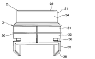
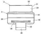
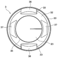
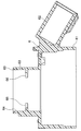
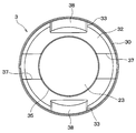
- FIG. 1 It is a side sectional view of an ultrasonic sensor concerning an embodiment. It is a side view of the ultrasonic transducer and elastic holding member which were shown by FIG. It is a front view of the ultrasonic transducer and elastic holding member which were shown by FIG. It is a bottom view of the ultrasonic transducer and elastic holding member which were shown by FIG. It is a sectional side view of the sensor case shown by FIG. It is a bottom view which shows one modification of the elastic holding member shown by FIG. It is a bottom view which shows another modification of the elastic holding member shown by FIG. It is a bottom view which shows another modification of the elastic holding member shown by FIG.
- FIG. 1 shows a schematic configuration in the case where the mounting target of the ultrasonic sensor 1 according to the present embodiment is a vehicle.
- the ultrasonic sensor 1 is configured to detect an object around the vehicle by transmitting and receiving ultrasonic waves in an on-vehicle state mounted on the vehicle. That is, the ultrasonic sensor 1 which concerns on this embodiment is comprised so that it may mount
- Bumper B has bumper outer surface B1 which comprises the outer surface of a vehicle, and bumper inner surface B2 which is the back. Further, the bumper B has a mounting hole B3 which is a through hole for mounting the ultrasonic sensor 1. That is, the mounting hole B3 is formed to penetrate the bumper B in the thickness direction of the bumper B.
- the ultrasonic sensor 1 includes an ultrasonic transducer 2, an elastic holding member 3, an elastic covering member 4, a damper member 5, a sensor case 6, and a filler 7.
- the ultrasonic transducer 2 is configured to be able to transmit and receive ultrasonic waves. That is, the ultrasonic transducer 2 is configured to transmit the search wave in the direction along the pointing axis and to receive the reflected wave by the object present around the vehicle.
- the ultrasonic transducer 2 has a columnar outer shape having a central axis line CL parallel to the pointing axis. Specifically, in the present embodiment, the ultrasonic transducer 2 is formed in a cylindrical shape extending in the axial direction parallel to the central axis line CL.
- the axial direction is defined as the upward direction in FIG. 1, that is, the arrow D direction.
- the axial direction is a direction substantially coinciding with the transmission direction of the ultrasonic waves in the ultrasonic transducer 2.
- the axial direction may also be referred to as a direction in which the ultrasonic transducer 2 protrudes in the ultrasonic sensor 1.
- the “tip side in the axial direction” corresponds to the upper side in FIG.
- the “proximal side in the axial direction” corresponds to the lower side in FIG.
- the ultrasonic transducer 2 has a transducer side surface 21, a transducer top surface 22, and a transducer bottom surface 23.
- the transducer side surface 21 is a cylindrical outer peripheral surface of the ultrasonic transducer 2 and is formed along the axial direction. That is, the transducer side surface 21 has a generatrix parallel to the central axis CL.
- the transducer top surface 22 is an ultrasonic wave transmitting / receiving surface provided on the end face on the tip side in the axial direction of the ultrasonic transducer 2, and has a substantially circular planar shape with the central axis CL as a normal direction. It is formed.
- the transducer bottom surface 23 is an end face on the proximal end side of the ultrasonic transducer 2 in the axial direction, and is formed in a substantially circular planar shape having the central axis CL as a normal direction.
- the ultrasonic transducer 2 has a projecting portion 24 and a supported portion 25.
- the projecting portion 24 is a portion on the tip side in the axial direction of the ultrasonic transducer 2 and is provided to protrude from the elastic holding member 3 to the tip side in the axial direction.
- the supported portion 25 is a portion on the proximal end side in the axial direction of the ultrasonic transducer 2 and is accommodated in the elastic holding member 3.
- the supported portion 25 is provided with a support groove 26 which is a groove for engaging with the elastic holding member 3.
- the elastic holding member 3 is a synthetic resin-based elastic member that elastically supports the ultrasonic transducer 2 and is a cylinder so as to accommodate the supported portion 25 while projecting the projecting portion 24 of the ultrasonic transducer 2. It is formed in the shape of a circle. In the present embodiment, the elastic holding member 3 has a substantially cylindrical shape having a cylindrical outer peripheral surface 30.
- the elastic holding member 3 is formed of an insulating and elastic synthetic resin elastic material.
- the synthetic resin-based elastic material is also referred to as a visco-elastic material or an elastomer.
- the elastic holding member 3 has a support cylindrical portion 31, a support bottom portion 32 and a leading projection 33.
- the elastic holding member 3 is integrally formed of silicone rubber or the like seamlessly.
- the support cylindrical portion 31 is formed in a cylindrical shape that is open at the tip end side in the axial direction so as to abut on the transmitter / receiver side 21 while accommodating the supported portion 25. Specifically, the support cylindrical portion 31 is provided so as to project from the support bottom portion 32 to the tip end side in the axial direction.
- a support protrusion 34 is provided on the inner wall surface of the support cylindrical portion 31 in a protruding manner. The support convex portion 34 is formed to engage with a support groove 26 provided in the supported portion 25 of the ultrasonic transducer 2.
- the support bottom portion 32 has a substantially ring shape in which a penetrating portion 35 which is a through hole penetrating in the axial direction is provided with respect to a thick plate-like portion having a predetermined thickness in the axial direction.
- the penetrating portion 35 is formed so that the inner diameter is smaller than the inner diameter of the support cylinder portion 31. That is, the support bottom portion 32 protrudes radially inward at the proximal end portion of the support cylindrical portion 31 in the axial direction so as to abut on the transducer bottom surface 23. Further, the support bottom portion 32 is formed as a thick portion whose thickness in the radial direction is larger than that of the support cylindrical portion 31 and the leading projection portion 33.
- the leading projection 33 protrudes from the bottom surface of the support bottom 32 toward the proximal end in the axial direction.
- two leading protrusions 33 are provided symmetrically about the central axis CL.
- the leading projection 33 has a tangential direction of a circle which is an intersection line of the outer peripheral surface 30 and the virtual plane in a bottom view. It is formed in the shape of a tongue having a substantially parallel width direction. Specifically, the leading projection 33 has a widthwise dimension equal to or less than half of the outer diameter of the support bottom 32. In addition, the leading projection 33 is formed such that the thickness in the radial direction is smaller than the thickness in the radial direction of the support bottom 32.
- An engagement recess 36 is provided on the outer peripheral surface 30 of the elastic holding member 3.
- the engagement recess 36 is recessed inward in the radial direction on the proximal end side in the axial direction with respect to the support cylindrical portion 31.
- the radial direction is a direction radially extending from the central axis line CL.
- the engagement recess 36 is a groove extending in the circumferential direction, and is provided in the support bottom 32.
- the circumferential direction is a direction surrounding the central axis line CL. That is, the circumferential direction is the circumferential direction of the virtual circle on the virtual plane centered on the intersection of the virtual plane and the central axis line CL.
- two engagement recesses 36 are provided symmetrically about the central axis CL.
- the engagement recess 36 is provided at a position corresponding to the leading projection 33 in the circumferential direction.
- the engagement recess 36 is provided at a proximal end in the axial direction of the support bottom 32 and in a position adjacent to the leading projection 33 in the axial direction.
- the leading projection 33 is formed to increase the opening width along the axial direction of the engagement recess 36 when elastically deformed in such a manner as to fall toward the central axis line CL.
- the elastic holding member 3 is further provided with an auxiliary recess 37 and a tapered surface 38 as a configuration for inducing or promoting elastic deformation in a manner in which the leading projection 33 falls toward the central axis line CL.
- the auxiliary recess 37 is a recess provided on the bottom surface of the support bottom 32, and is formed to open on the proximal side in the axial direction.
- two auxiliary recesses 37 are provided symmetrically about the central axis CL. Specifically, the leading projections 33 and the auxiliary recesses 37 are alternately arranged in the circumferential direction.
- the auxiliary recess 37 is formed in a substantially trapezoidal shape in bottom view.
- the auxiliary recess 37 is provided between the outer peripheral surface 30 of the elastic holding member 3 and the inner peripheral surface of the penetrating portion 35. That is, each of the two auxiliary recesses 37 is formed as an independent hole which does not communicate with the space outside the outer peripheral surface 30 in the radial direction or the space inside the penetrating portion 35.
- the tapered surface 38 is provided continuously with the outer peripheral surface 30 of the elastic holding member 3 at the end portion in the axial direction of the leading projection 33. That is, the tapered surface 38 is formed as an outward inclined slope provided at the projecting end of the leading projection 33 projecting from the support bottom 32, in other words, at the distal end.
- the elastic covering member 4 is configured to cover the projecting portion 24 of the ultrasonic transducer 2 in a close contact state.
- the elastic covering member 4 has a cylindrical portion 41 and a flange portion 42.
- the elastic covering member 4 is integrally and seamlessly formed of a synthetic resin-based elastic material such as silicone rubber having an insulating property and elasticity.
- the cylindrical portion 41 is a cylindrical portion provided along the central axis CL, and has an inner peripheral surface in the shape of a cylindrical inner surface. The inner peripheral surface is formed in close contact with a portion corresponding to the projecting portion 24 of the transmitter / receiver side 21.
- the cylindrical portion 41 is inserted between the transducer side surface 21 and the mounting hole B3 when the projecting portion 24 of the ultrasonic transducer 2 is inserted into the mounting hole B3 and the ultrasonic sensor 1 is mounted on the bumper B. It is supposed to be held.
- the cylindrical portion 41 is formed such that the tip end surface in the axial direction is substantially flush with the bumper outer surface B1.
- the flange portion 42 is formed in a ring shape projecting outward in the radial direction from the proximal end portion in the axial direction of the cylindrical portion 41.
- the flange portion 42 is in contact with the tip end portion in the axial direction of the support cylindrical portion 31 in a state where the elastic covering member 4 is attached to the ultrasonic transducer 2. Further, when the ultrasonic sensor 1 is mounted on the bumper B, the flange portion 42 is held between the sensor case 6 and the bumper inner surface B2.
- the damper member 5 is a disk-shaped member having an outer diameter corresponding to the inner diameter of the through portion 35, and is fitted into a cylindrical space inside the through portion 35.
- the damper member 5 is formed of a foamed elastic material such as foamed silicone having insulation and elasticity so as to suppress the vibration transmission from the ultrasonic transducer 2 to the sensor case 6.
- a sensor case 6 constituting a housing of the ultrasonic sensor 1 is integrally formed of a hard synthetic resin such as polypropylene.
- the sensor case 6 is configured to hold and retain the elastic holding member 3. That is, the sensor case 6 elastically supports the ultrasonic transducer 2 via the elastic holding member 3.
- the sensor case 6 includes a case body 61, a connector 62, and a case cylinder 63.
- a case body 61 the configuration of the sensor case 6 will be described in detail with reference to FIGS. 1 and 5.
- the case main body portion 61 is a box-shaped portion formed in a substantially rectangular parallelepiped shape, and is formed in a bottomed cylindrical shape in which a base end side in the axial direction is opened. Inside the case main body portion 61, a circuit board, a wiring portion, and the like (not shown) are accommodated.
- the connector portion 62 is extended outward from the side wall portion of the case main body portion 61 in order to electrically connect the ultrasonic sensor 1 to another device such as an electronic control unit.
- the case cylindrical portion 63 is provided so as to protrude from the case main body portion 61 at the tip end side in the axial direction.
- the case cylindrical portion 63 is formed in a cylindrical shape having an inner circumferential surface 64 in close contact with the outer circumferential surface 30 of the elastic holding member 3. That is, the inner diameter of the case cylindrical portion 63 is set to correspond to the outer diameter of the outer peripheral surface 30 of the elastic holding member 3.
- a tip end opening portion 65 opened at the tip end side in the axial direction is provided at the tip end portion of the case cylindrical portion 63 in the axial direction.
- a cylindrical space inside the case cylindrical portion 63 is provided to communicate with a space inside the case main body portion 61.
- the space inside the case cylinder 63 and the space inside the case body 61 will be collectively referred to as the space inside the sensor case 6.
- the space inside the sensor case 6 is filled with a filler 7 such as silicone rubber having an insulating property and elasticity.
- the filler 7 is also filled in the auxiliary recess 37.
- an engagement convex portion 66 is provided in the case cylindrical portion 63.
- the engagement convex portion 66 is provided so as to protrude radially inward on the proximal end side in the axial direction with respect to the distal end opening 65.
- the engagement convex portion 66 is formed to be fitted to the engagement recess 36 by being accommodated in the engagement recess 36 provided in the elastic holding member 3.
- the leading projection 33 abuts on the engagement convex portion 66, whereby the leading projection 33 is on the central axis CL side. It is configured to be elastically deformed in a manner of falling down.
- the tapered surface 38 provided at the end of the leading projection 33 in the axial direction abuts on the engagement projection 66 when the elastic holding member 3 is inserted into the case cylindrical portion 63 as described above.
- the elastic deformation of the leading projection 33 of the embodiment is induced.
- the auxiliary recess 37 is provided so as to reduce the rigidity of the wall portion by thinning the wall portion of the support bottom portion 32 extended along the elastic deformation direction of the leading projection 33.
- the supported portion 25 on the base end side in the axial direction of the ultrasonic transducer 2 is inserted into the support cylindrical portion 31 in the elastic holding member 3 Be done.
- the transmitter bottom surface 23 which is the end face on the proximal end side in the axial direction of the ultrasonic transducer 2 is in contact with the support bottom portion 32 protruding inward in the radial direction at the proximal end of the support cylindrical portion 31.
- the support convex portion 34 in the elastic holding member 3 engages with the support groove 26 provided in the supported portion 25 in the ultrasonic transducer 2.
- the ultrasonic transducer 2 is elastically supported by the elastic holding member 3.
- the elastic holding member 3 elastically supporting the ultrasonic transducer 2 is inserted into the case cylindrical portion 63 in the sensor case 6 along the central axis line CL from the side of the leading projection 33 in the base end side in the axial direction. Be done.
- the engagement convex portion 66 provided so as to protrude inward in the radial direction in the case cylindrical portion 63 is accommodated in the engagement concave portion 36 provided inward in the radial direction by the elastic holding member 3. That is, the engagement projection 66 engages with the engagement recess 36.
- the sensor case 6 holds and holds the elastic holding member 3.
- the leading projection 33 abuts on the engagement convex portion 66 before the engagement convex portion 66 engages with the engagement concave portion 36.
- the leading projection 33 elastically deforms in a manner of being inclined toward the central axis line CL.
- the leading projection 33 is provided at a position corresponding to the engagement recess 36 in the circumferential direction surrounding the central axis CL. For this reason, by the elastic deformation of the leading projection 33 in the above-described manner, the opening width along the axial direction of the opening of the outer edge in the radial direction of the engagement recess 36 is increased. Thereby, the engagement between the engagement convex portion 66 and the engagement concave portion 36 can be promoted well.
- the elastic holding member 3 that elastically supports the ultrasonic transducer 2 and the case cylindrical portion 63 in the sensor case 6 have a predetermined positional relationship in the axial direction. It is set.
- the elastic deformation of the leading projection 33 is restored. The impact at the time of this restoration produces a feeling of notch. For this reason, the operator in the manufacturing process of the ultrasonic sensor 1 accurately determines that the elastic holding member 3 and the case cylindrical portion 63 have been set in the predetermined positional relationship in the axial direction based on the feeling of notch. can do.
- the support bottom portion 32 provided with the engagement recess 36 is formed as a thick portion. That is, the support bottom portion 32 is formed so that the thickness in the radial direction is larger than that of the support cylindrical portion 31 and the leading projection portion 33. Also, the support bottom portion 32 is provided as a thick plate-like portion having a predetermined thickness in the axial direction, specifically, a thickness greater than the thickness in the radial direction of the support cylindrical portion 31 and the leading projection 33. It is done. According to this configuration, the engagement state between the elastic holding member 3 and the sensor case 6 after the assembly of the elastic holding member 3 to the sensor case 6 is completed can be favorably held. That is, after the assembly of the elastic holding member 3 to the sensor case 6 is completed, the elastic holding member 3 can be favorably suppressed from falling off the sensor case 6.
- the engagement recess 36 is provided at a proximal end in the axial direction of the support bottom 32 and in a position adjacent to the leading projection 33 in the axial direction.
- the leading projection 33 is elastically deformed in such a manner that the leading projection 33 falls toward the central axis line CL due to the contact between the leading projection 33 and the engagement projection 66, whereby the opening width of the engagement recess 36 is good. Increase. Therefore, according to such a configuration, the engagement between the engagement convex portion 66 and the engagement concave portion 36 can be promoted well.
- the elastic holding member 3 has a tapered surface 38 provided at the end of the leading projection 33 in the axial direction so as to be continuous with the outer circumferential surface 30.
- the tapered surface 38 elastically deforms the leading projection 33 in such a manner that the tapered surface 38 falls toward the central axis line CL by coming into contact with the engagement convex portion 66 when the elastic holding member 3 is inserted into the case cylindrical portion 63. There is. Therefore, according to such a configuration, elastic deformation of the leading projection 33 can be induced well.
- the support bottom portion 32 has an auxiliary recess 37 opening on the proximal side in the axial direction.
- the auxiliary recess 37 reduces the rigidity of the wall portion of the support bottom portion 32 extended along the elastic deformation direction of the leading projection 33 by thinning the wall portion. Therefore, the auxiliary recess 37 promotes the elastic deformation of the leading projection 33 due to the contact with the engagement convex 66 when the elastic holding member 3 is inserted into the case cylinder 63. Therefore, according to such a configuration, the assembly of the elastic holding member 3 to the sensor case 6 can be performed well.
- the space inside the sensor case 6 is filled with the filler 7.
- the filler 7 is also filled in the auxiliary recess 37.
- the workability at the time of manufacturing the ultrasonic sensor 1 can be improved as compared with the conventional case.
- the present disclosure is not limited to the mode of mounting the ultrasonic sensor 1 on the bumper B. That is, the ultrasonic sensor 1 can also be attached to the front grille or the vehicle body panel in the case of a vehicle.
- the ultrasonic sensor 1 is not limited to being used in vehicles. That is, for example, the ultrasonic sensor 1 can also be attached to a transport machine provided in a factory or the like, agricultural equipment (for example, a cultivator), a small aircraft, or the like.
- the ultrasonic sensor 1 is not limited to the configuration that can transmit and receive ultrasonic waves. That is, for example, the ultrasonic sensor 1 may have a configuration that can only transmit ultrasonic waves. Alternatively, the ultrasonic sensor 1 may have only a function of receiving a reflected wave of an object present in the surroundings of a probe wave which is an ultrasonic wave transmitted from another ultrasonic transmitter.
- each part is also not limited to the above specific example.
- the number of the leading projections 33, the engagement recesses 36, the auxiliary recesses 37, and the number of the engagement projections 66 are not particularly limited. Therefore, for example, the leading protrusion 33, the engagement recess 36, and the engagement protrusion 66 may be provided one by one. Alternatively, for example, three guiding protrusions 33, three engaging recesses 36, and three engaging protrusions 66 may be provided.
- the shape of the auxiliary recess 37 is not limited to the above specific example. That is, for example, the plurality of auxiliary recesses 37 may be configured by a plurality of circular holes, elliptical holes, or square holes arranged in the radial direction.
- the auxiliary recess 37 may be provided so as to open outward in the radial direction. That is, the auxiliary recess 37 may be formed to communicate with the space outside the outer circumferential surface 30.
- the auxiliary recess 37 may be provided to open inward in the radial direction. That is, the auxiliary recess 37 may be provided in communication with the space inside the through portion 35 in the radial direction.
- the auxiliary recess 37 may be provided to communicate the space inside the through portion 35 with the space outside the outer circumferential surface 30. That is, the auxiliary recess 37 may be formed in the shape of a slit provided along the diameter of the support bottom 32 in a bottom view.
- the elastic covering member 4 is configured separately from the elastic holding member 3.
- the present disclosure is not limited to such an aspect. That is, the elastic covering member 4 may be integrally formed with the elastic holding member 3 without joint.
- the plurality of components which are integrally formed integrally without each other may be formed by bonding separate members to each other.
- a plurality of components formed by pasting separate members to one another may be formed seamlessly and integrally.
- the plurality of components formed of the same material may be formed of different materials.
- a plurality of components that have been formed of different materials may be formed of the same material.
- the modified example is also not limited to the above example. Also, multiple variants may be combined with one another. Furthermore, all or part of the above embodiment and all or part of the modification may be combined with each other.
Priority Applications (3)
| Application Number | Priority Date | Filing Date | Title |
|---|---|---|---|
| DE112018005211.7T DE112018005211T5 (de) | 2017-11-02 | 2018-10-04 | Ultraschallsensor |
| CN201880071254.9A CN111295889B (zh) | 2017-11-02 | 2018-10-04 | 超声波传感器 |
| US16/865,020 US11307305B2 (en) | 2017-11-02 | 2020-05-01 | Ultrasonic sensor |
Applications Claiming Priority (2)
| Application Number | Priority Date | Filing Date | Title |
|---|---|---|---|
| JP2017-212694 | 2017-11-02 | ||
| JP2017212694A JP6897502B2 (ja) | 2017-11-02 | 2017-11-02 | 超音波センサ |
Related Child Applications (1)
| Application Number | Title | Priority Date | Filing Date |
|---|---|---|---|
| US16/865,020 Continuation US11307305B2 (en) | 2017-11-02 | 2020-05-01 | Ultrasonic sensor |
Publications (1)
| Publication Number | Publication Date |
|---|---|
| WO2019087675A1 true WO2019087675A1 (ja) | 2019-05-09 |
Family
ID=66331688
Family Applications (1)
| Application Number | Title | Priority Date | Filing Date |
|---|---|---|---|
| PCT/JP2018/037265 WO2019087675A1 (ja) | 2017-11-02 | 2018-10-04 | 超音波センサ |
Country Status (5)
| Country | Link |
|---|---|
| US (1) | US11307305B2 (de) |
| JP (1) | JP6897502B2 (de) |
| CN (1) | CN111295889B (de) |
| DE (1) | DE112018005211T5 (de) |
| WO (1) | WO2019087675A1 (de) |
Families Citing this family (2)
| Publication number | Priority date | Publication date | Assignee | Title |
|---|---|---|---|---|
| JP7024662B2 (ja) * | 2018-08-24 | 2022-02-24 | 株式会社デンソー | リテーナ部材 |
| US11899143B2 (en) | 2021-07-12 | 2024-02-13 | Robert Bosch Gmbh | Ultrasound sensor array for parking assist systems |
Citations (4)
| Publication number | Priority date | Publication date | Assignee | Title |
|---|---|---|---|---|
| JP2003032794A (ja) * | 2002-05-14 | 2003-01-31 | Denso Corp | 超音波振動子およびその超音波振動子を有する超音波センサ |
| JP2003261971A (ja) * | 2002-03-07 | 2003-09-19 | Maruichi Kk | 排水口の被覆部材 |
| JP2015200579A (ja) * | 2014-04-08 | 2015-11-12 | 株式会社デンソー | 車両用超音波センサ及びそれを備えた車両用距離検出器 |
| JP2017175291A (ja) * | 2016-03-22 | 2017-09-28 | 株式会社デンソー | 超音波センサ |
Family Cites Families (8)
| Publication number | Priority date | Publication date | Assignee | Title |
|---|---|---|---|---|
| EP1343004A3 (de) * | 2002-03-06 | 2005-05-11 | NGK Spark Plug Co., Ltd. | Gassensor und Vorrichtung zur Erfassung der Gaskonzentration |
| JP3746728B2 (ja) * | 2002-04-10 | 2006-02-15 | 日本特殊陶業株式会社 | センサおよびその製造方法 |
| JP4306561B2 (ja) * | 2004-08-11 | 2009-08-05 | 株式会社デンソー | 超音波センサ |
| JP5451563B2 (ja) | 2010-09-14 | 2014-03-26 | 日立オートモティブシステムズ株式会社 | モータ制御装置 |
| KR101890616B1 (ko) * | 2012-02-20 | 2018-08-22 | 현대모비스 주식회사 | 차량용 센서 장착 구조체 |
| JP6577270B2 (ja) | 2015-07-07 | 2019-09-18 | 株式会社東海理化電機製作所 | 故障診断回路、および故障診断方法 |
| JP6559006B2 (ja) * | 2015-08-06 | 2019-08-14 | ブランソン・ウルトラソニックス・コーポレーション | 超音波振動伝達機構部の保持構造 |
| JP2017212694A (ja) | 2016-05-27 | 2017-11-30 | キヤノン株式会社 | 情報処理装置、情報処理方法及びプログラム |
-
2017
- 2017-11-02 JP JP2017212694A patent/JP6897502B2/ja active Active
-
2018
- 2018-10-04 WO PCT/JP2018/037265 patent/WO2019087675A1/ja active Application Filing
- 2018-10-04 DE DE112018005211.7T patent/DE112018005211T5/de active Pending
- 2018-10-04 CN CN201880071254.9A patent/CN111295889B/zh active Active
-
2020
- 2020-05-01 US US16/865,020 patent/US11307305B2/en active Active
Patent Citations (4)
| Publication number | Priority date | Publication date | Assignee | Title |
|---|---|---|---|---|
| JP2003261971A (ja) * | 2002-03-07 | 2003-09-19 | Maruichi Kk | 排水口の被覆部材 |
| JP2003032794A (ja) * | 2002-05-14 | 2003-01-31 | Denso Corp | 超音波振動子およびその超音波振動子を有する超音波センサ |
| JP2015200579A (ja) * | 2014-04-08 | 2015-11-12 | 株式会社デンソー | 車両用超音波センサ及びそれを備えた車両用距離検出器 |
| JP2017175291A (ja) * | 2016-03-22 | 2017-09-28 | 株式会社デンソー | 超音波センサ |
Also Published As
| Publication number | Publication date |
|---|---|
| DE112018005211T5 (de) | 2020-06-18 |
| JP6897502B2 (ja) | 2021-06-30 |
| US11307305B2 (en) | 2022-04-19 |
| CN111295889B (zh) | 2022-04-05 |
| CN111295889A (zh) | 2020-06-16 |
| US20200256984A1 (en) | 2020-08-13 |
| JP2019087803A (ja) | 2019-06-06 |
Similar Documents
| Publication | Publication Date | Title |
|---|---|---|
| JP4306561B2 (ja) | 超音波センサ | |
| EP2808694B2 (de) | Ultraschallwellenvorrichtung | |
| US10288730B2 (en) | Ultrasonic sensor | |
| JP6443322B2 (ja) | 超音波センサ | |
| JP2007284035A (ja) | 超音波センサ | |
| WO2019087675A1 (ja) | 超音波センサ | |
| CN110431445B (zh) | 超声波传感器 | |
| CN107367732B (zh) | 超声波传感器 | |
| CN106133549A (zh) | 车辆用超声波传感器及具备该传感器的车辆用距离检测器 | |
| WO2013161221A1 (ja) | 車両用超音波センサ装置及び車両用超音波センサ装置の組み付け方法 | |
| US20140096609A1 (en) | Ultrasonic sensor device and method for assembling the same | |
| WO2019102755A1 (ja) | 超音波センサおよびリテーナ | |
| JP2019097153A (ja) | 超音波センサおよびリテーナ | |
| JP5984082B2 (ja) | 超音波センサ | |
| WO2020039854A1 (ja) | リテーナ部材 | |
| JP2020082986A (ja) | ベゼル式ソナー | |
| JP6148598B2 (ja) | コネクタ | |
| JP7294223B2 (ja) | 超音波センサおよび振動吸収体 | |
| US11049483B2 (en) | Acoustic sensor having a housing and a diaphragm element situated on this housing | |
| JP7334667B2 (ja) | 超音波センサおよびセンサ取付具 | |
| JP7243674B2 (ja) | 車載構造 | |
| JP6148599B2 (ja) | コネクタ |
Legal Events
| Date | Code | Title | Description |
|---|---|---|---|
| 121 | Ep: the epo has been informed by wipo that ep was designated in this application |
Ref document number: 18871968 Country of ref document: EP Kind code of ref document: A1 |
|
| 122 | Ep: pct application non-entry in european phase |
Ref document number: 18871968 Country of ref document: EP Kind code of ref document: A1 |