WO2019087385A1 - 遠心圧縮機及びこの遠心圧縮機を備えたターボチャージャ - Google Patents
遠心圧縮機及びこの遠心圧縮機を備えたターボチャージャ Download PDFInfo
- Publication number
- WO2019087385A1 WO2019087385A1 PCT/JP2017/039909 JP2017039909W WO2019087385A1 WO 2019087385 A1 WO2019087385 A1 WO 2019087385A1 JP 2017039909 W JP2017039909 W JP 2017039909W WO 2019087385 A1 WO2019087385 A1 WO 2019087385A1
- Authority
- WO
- WIPO (PCT)
- Prior art keywords
- scroll
- flow path
- wall
- flow
- wall surface
- Prior art date
Links
Images


Classifications
-
- F—MECHANICAL ENGINEERING; LIGHTING; HEATING; WEAPONS; BLASTING
- F04—POSITIVE - DISPLACEMENT MACHINES FOR LIQUIDS; PUMPS FOR LIQUIDS OR ELASTIC FLUIDS
- F04D—NON-POSITIVE-DISPLACEMENT PUMPS
- F04D17/00—Radial-flow pumps, e.g. centrifugal pumps; Helico-centrifugal pumps
- F04D17/08—Centrifugal pumps
- F04D17/10—Centrifugal pumps for compressing or evacuating
-
- F—MECHANICAL ENGINEERING; LIGHTING; HEATING; WEAPONS; BLASTING
- F04—POSITIVE - DISPLACEMENT MACHINES FOR LIQUIDS; PUMPS FOR LIQUIDS OR ELASTIC FLUIDS
- F04D—NON-POSITIVE-DISPLACEMENT PUMPS
- F04D29/00—Details, component parts, or accessories
- F04D29/40—Casings; Connections of working fluid
- F04D29/42—Casings; Connections of working fluid for radial or helico-centrifugal pumps
- F04D29/44—Fluid-guiding means, e.g. diffusers
- F04D29/441—Fluid-guiding means, e.g. diffusers especially adapted for elastic fluid pumps
-
- F—MECHANICAL ENGINEERING; LIGHTING; HEATING; WEAPONS; BLASTING
- F02—COMBUSTION ENGINES; HOT-GAS OR COMBUSTION-PRODUCT ENGINE PLANTS
- F02B—INTERNAL-COMBUSTION PISTON ENGINES; COMBUSTION ENGINES IN GENERAL
- F02B39/00—Component parts, details, or accessories relating to, driven charging or scavenging pumps, not provided for in groups F02B33/00 - F02B37/00
-
- F—MECHANICAL ENGINEERING; LIGHTING; HEATING; WEAPONS; BLASTING
- F04—POSITIVE - DISPLACEMENT MACHINES FOR LIQUIDS; PUMPS FOR LIQUIDS OR ELASTIC FLUIDS
- F04D—NON-POSITIVE-DISPLACEMENT PUMPS
- F04D29/00—Details, component parts, or accessories
- F04D29/40—Casings; Connections of working fluid
- F04D29/42—Casings; Connections of working fluid for radial or helico-centrifugal pumps
- F04D29/4206—Casings; Connections of working fluid for radial or helico-centrifugal pumps especially adapted for elastic fluid pumps
- F04D29/4226—Fan casings
- F04D29/4233—Fan casings with volutes extending mainly in axial or radially inward direction
-
- F—MECHANICAL ENGINEERING; LIGHTING; HEATING; WEAPONS; BLASTING
- F05—INDEXING SCHEMES RELATING TO ENGINES OR PUMPS IN VARIOUS SUBCLASSES OF CLASSES F01-F04
- F05D—INDEXING SCHEME FOR ASPECTS RELATING TO NON-POSITIVE-DISPLACEMENT MACHINES OR ENGINES, GAS-TURBINES OR JET-PROPULSION PLANTS
- F05D2220/00—Application
- F05D2220/40—Application in turbochargers
-
- F—MECHANICAL ENGINEERING; LIGHTING; HEATING; WEAPONS; BLASTING
- F05—INDEXING SCHEMES RELATING TO ENGINES OR PUMPS IN VARIOUS SUBCLASSES OF CLASSES F01-F04
- F05D—INDEXING SCHEME FOR ASPECTS RELATING TO NON-POSITIVE-DISPLACEMENT MACHINES OR ENGINES, GAS-TURBINES OR JET-PROPULSION PLANTS
- F05D2240/00—Components
- F05D2240/10—Stators
- F05D2240/12—Fluid guiding means, e.g. vanes
-
- F—MECHANICAL ENGINEERING; LIGHTING; HEATING; WEAPONS; BLASTING
- F05—INDEXING SCHEMES RELATING TO ENGINES OR PUMPS IN VARIOUS SUBCLASSES OF CLASSES F01-F04
- F05D—INDEXING SCHEME FOR ASPECTS RELATING TO NON-POSITIVE-DISPLACEMENT MACHINES OR ENGINES, GAS-TURBINES OR JET-PROPULSION PLANTS
- F05D2240/00—Components
- F05D2240/10—Stators
- F05D2240/14—Casings or housings protecting or supporting assemblies within
-
- F—MECHANICAL ENGINEERING; LIGHTING; HEATING; WEAPONS; BLASTING
- F05—INDEXING SCHEMES RELATING TO ENGINES OR PUMPS IN VARIOUS SUBCLASSES OF CLASSES F01-F04
- F05D—INDEXING SCHEME FOR ASPECTS RELATING TO NON-POSITIVE-DISPLACEMENT MACHINES OR ENGINES, GAS-TURBINES OR JET-PROPULSION PLANTS
- F05D2250/00—Geometry
- F05D2250/50—Inlet or outlet
- F05D2250/52—Outlet
Definitions
- the present disclosure relates to a centrifugal compressor and a turbocharger provided with the centrifugal compressor.
- At least one embodiment of the present disclosure is directed to providing a centrifugal compressor with improved efficiency at a low flow operating point and a turbocharger including the centrifugal compressor.
- a centrifugal compressor comprising an impeller and a housing, wherein
- the housing is A scroll portion in which a scroll flow passage having a spiral shape is formed on the outer peripheral side of the impeller;
- a diffuser flow that includes a pair of flow passage walls provided at intervals in a direction in which the rotational axis of the impeller extends, and communicates with the scroll flow passage along a circumferential direction of the scroll flow passage radially inside the impeller And a diffuser portion forming a passage between the pair of flow passage walls,
- the pair of flow path walls are A first flow path wall, And a second flow path wall positioned on the scroll center side of the scroll flow path with respect to the first flow path wall in a direction in which the rotation axis extends.
- the second flow path wall includes a portion of the inner wall surface positioned on the radially inner side of the inner wall surface of the scroll flow path, and the inner wall surface including the second flow path wall includes the rotation axis.
- At least one concave arc portion having a radius of curvature in the scroll channel in a cross section of the housing by a plane;
- the inclination angle between the tangential direction of the radially outer end edge of the impeller of the outermost concave arc portion in the radial direction of the impeller of the at least one concave arc portion and the direction perpendicular to the rotation axis is Has a distribution along the circumferential direction of the scroll channel,
- the distribution of the inclination angle is Have a minimum value or a minimum value within the range of the central angle from 30 ° to 210 °.
- the direction of the swirling flow is such that the swirling flow circulating while swirling in the scroll flow passage along the inner wall surface of the scroll flow passage makes just one round along the inner wall surface of the scroll flow passage Since the angle between the flow direction of the compressed fluid discharged from the diffuser channel and the flow direction of the compressed fluid decreases, the interference between the swirling flow and the flow of the compressed fluid discharged from the diffuser channel is suppressed, and the flow in the scroll channel is suppressed. The occurrence of peeling is reduced. As a result, the efficiency of the centrifugal compressor at the low flow rate operating point can be improved.
- the distribution of the tilt angles has local minima or minima within the range of the central angle from 30 ° to 120 °.
- the flow passage area of the scroll flow passage decreases from the outlet side toward the tongue. Due to such a shape of the scroll channel, the inclination angle of the concave arc portion tends to be larger as it is closer to the tongue. According to the configuration of the above (2), if the scroll flow path is formed without being aware of the magnitude of the tilt angle, the tilt angle tends to increase, and this tilt angle is in the range of 30 ° to 120 ° central angle
- this inclination angle can be reduced in the range of the central angle from 30 ° to 210 °, so that the swirl flow and the diffuser flow passage are discharged. Interference with the flow of compressed fluid is further suppressed, and the occurrence of separation in the scroll channel is further reduced. As a result, the efficiency of the centrifugal compressor at the low flow rate operating point can be improved.
- the second flow path wall is A flat inner wall which defines the diffuser flow path and which is flat and perpendicular to the rotation axis; A convex inner wall surface which defines the scroll channel and is convexly curved with respect to the scroll channel; At least one concave inner wall that defines the at least one concave arc portion in a cross section of the housing according to a plane that defines the scroll flow path and includes a plane of rotation, the at least one concave inner wall of the at least one concave inner wall; At least one concave inner wall surface in which the outermost concave inner wall surface in the radial direction of the impeller is connected to the convex arc portion; It includes an end face connecting the flat inner wall surface and the convex inner wall surface at the outermost side of the flat inner wall surface in the radial direction of the impeller.
- the interference between the swirling flow and the flow of the compressed fluid discharged from the diffuser flow path can be suppressed to reduce the occurrence of separation in the scroll flow path and to define the diffuser flow path
- the fact that the inner wall is flat and perpendicular to the axis of rotation can also facilitate the processing of the diffuser channel.
- the outer diameter of the diffuser flow passage around the rotation axis has a distribution in the circumferential direction of the diffuser flow passage, and the distribution of the outer diameter of the diffuser flow passage is the central angle from 30 ° to 210 °
- the maximum value or the maximum value is within the range of
- the inclination angle of the concave arc portion can be minimized or minimized in the range of the central angle from 30 ° to 210 °, the swirl flow and the compression discharged from the diffuser flow path Interference with the flow of fluid is suppressed to reduce the occurrence of separation in the scroll channel. As a result, the efficiency of the centrifugal compressor at the low flow rate operating point can be improved.
- the distance from the rotation axis to the scroll center of the scroll flow channel has a distribution in the circumferential direction of the scroll flow channel, and the distribution of the distance is minimized within the range of the central angle from 30 ° to 210 ° It has a value or a minimum value.
- the inclination angle of the concave arc portion can be minimized or minimized in the range of the central angle from 30 ° to 210 °, the swirl flow and the compression discharged from the diffuser flow path Interference with the flow of fluid is suppressed to reduce the occurrence of separation in the scroll channel. As a result, the efficiency of the centrifugal compressor at the low flow rate operating point can be improved.
- a turbocharger according to at least one embodiment of the present disclosure is: The centrifugal compressor according to any one of the above (1) to (5) is provided.
- a swirl flow circulating while swirling in the scroll flow path along the inner wall surface of the scroll flow path is around the circumference just along the inner wall surface of the scroll flow path. Since the angle between the flow direction and the flow direction of the compressed fluid discharged from the diffuser flow path is small, the interference between the swirl flow and the flow of the compressed fluid discharged from the diffuser flow path is suppressed, and the scroll flow is reduced. The occurrence of delamination in the channel is reduced. As a result, the efficiency of the centrifugal compressor at the low flow rate operating point can be improved.
- FIG. 1 is a partial cross-sectional view of a centrifugal compressor housing according to a plane including a rotational axis of the centrifugal compressor according to an embodiment of the present disclosure.
- FIG. 7 is a streamline diagram showing how compressed air discharged from a diffuser flow passage swirls along an inner wall surface of a scroll flow passage in a centrifugal compressor according to an embodiment of the present disclosure. It is a schematic diagram for demonstrating the principle which a rotational flow and the flow of the compressed air discharged
- FIG. 5 is an enlarged partial cross-sectional view of a second flow passage wall of a centrifugal compressor according to an embodiment of the present disclosure.
- centrifugal compressor according to an embodiment of the present disclosure will be described by taking a centrifugal compressor of a turbocharger as an example.
- the centrifugal compressor in the present disclosure is not limited to a centrifugal compressor of a turbocharger, and may be any centrifugal compressor operating alone.
- the fluid compressed by this compressor is air, but can be replaced by any fluid.
- the centrifugal compressor 1 includes a housing 2 and an impeller 3 rotatably provided around the rotational axis L in the housing 2.
- the housing 2 has a pair of scrolls 4 in which a scroll flow passage 5 having a spiral shape is formed on the outer peripheral side of the impeller 3 and a pair of clearances provided in the extending direction of the rotation axis L.
- It has the flow path wall 7, ie, the diffuser portion 6 including the first flow path wall 7a and the second flow path wall 7b, and the cylindrical air inlet portion 9.
- the second channel wall 7b is located on the scroll center O S side of the scroll passage 5 to the first channel wall 7a in the direction of extension of the rotation axis L.
- a diffuser flow path 8 communicating with the scroll flow path 5 is formed along the circumferential direction of the scroll flow path 5 inside the impeller 3 in the radial direction .
- the air flowing into the centrifugal compressor 1 via the air inlet 9 is compressed by the impeller 3 to be compressed air.
- the compressed air flows through the diffuser flow path 8 into the scroll flow path 5, and then flows through the scroll flow path 5 and is discharged from the centrifugal compressor 1.
- the centrifugal compressor 1 If the amount of air flowing into the centrifugal compressor 1 is small, such as when the turbocharger operates at a low speed, the centrifugal compressor 1 operates in a stall state, and the efficiency decreases. In such an operation area, occurrence of a large scale peeling is confirmed in the scroll channel 5. As a result of intensive studies, the present inventors have found one of the factors causing such exfoliation. The principle of occurrence of peeling due to the factor will be described below.
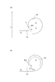
- the circumferential position in the scroll channel 5 from the tongue 4a of the scroll 4 (see FIG. 2) toward the outlet of the scroll channel 5 is taken as the rotational axis L with reference to the tongue 4a.
- a central angle ⁇ as a center. Therefore, the central angle ⁇ representing the circumferential position of the tongue 4a is 0 °.
- the flow f 1 of the compressed air discharged from the diffuser channel 8 near the tongue 4 a circulates the scroll channel 5 while turning along the inner wall surface of the scroll channel 5.
- FIG. 4A in a cross section of the housing 2 (see FIG. 2) including the rotation axis L, a tangent of a portion 5a1 of the inner wall surface 5a of the scroll flow passage 5 connected to the second flow passage wall 7b.
- a tangent of a portion 5a1 of the inner wall surface 5a of the scroll flow passage 5 connected to the second flow passage wall 7b As the inclination angle ⁇ between the direction A and the direction B perpendicular to the rotation axis L is larger, ie, closer to 90 °, as shown in FIG. 4B, along the inner wall surface 5a of the scroll passage 5 a turning flow f 2 of the compressed air flowing through Te, the angle ⁇ between the flow f 3 of the compressed air discharged from the diffuser flow path 8 is increased. Then, to avoid interference to the flow f 3 of the compressed air tends to flow from the diffuser flow path 8 to the scroll flow path 5 is turning flow f 2 closes, so that peeling at the portion where the interference occurs occurs.
- the second flow path wall 7b delimits the diffuser flow path 8 and is connected to the flat inner wall 21 which is flat and perpendicular to the rotation axis L and the most radially outer side of the flat inner wall 21 vertically to the flat inner wall 21
- a concave inner wall 24 which is curved.
- the inner wall surface 5a of the scroll passage 5 the virtual line L' parallel virtual line L the scroll center O S as the rotation axis L radially inner portion 5a2 and radially outward with respect to It distinguishes with the part 5a3 of.
- the end surface 22, the convex inner wall surface 23 and the concave inner wall surface 24 are a part of the portion 5 a 2 of the inner wall surface 5 a.
- the center of curvature of the convex arc portion 23a formed by the convex inner wall surface 23 Curving in a concave shape with respect to the scroll flow path 5 means positioning outside the flow path 5 means that the curvature of the concave arc portion 24 a formed by the concave inner wall surface 24 in the cross section of the housing 2 including the rotation axis L It means that the center is located inside the scroll channel 5.
- the present inventors obtained the result that peeling tends to occur in the range of central angle ⁇ from 30 ° to 210 ° by performing CFD analysis. This is because when the stable swirling flow is formed in the scroll flow passage 5, the swirling flow in the scroll flow passage 5 and the flow of the compressed air discharged from the diffuser flow passage 8 will not gradually interfere with each other. Such interference is likely to occur toward the upstream side of the scroll channel 5. Therefore, the occurrence of peeling can be effectively reduced by setting the cross-sectional shape of the scroll channel 5 to a shape such that the inclination angle ⁇ becomes smaller on the upstream side.
- the cross-sectional shape of the scroll passage 5 shown in FIG. 5 is a shape in one cross section of the housing 2 (see FIG. 2).
- the cross-sectional shape of the scroll channel 5 actually changes in the circumferential direction. Therefore, the inclination angle ⁇ changes in the circumferential direction. That is, the inclination angle ⁇ has a distribution along the circumferential direction of the scroll channel 5. Therefore, as shown in FIG. 6, according to the above knowledge obtained by the present inventor, in the range of the circumferential direction position of the scroll channel 5 in which the central angle ⁇ is in the range of 30 ° to 210 °, With the distribution having the minimum value, the occurrence of peeling can be effectively reduced.
- the distribution of the inclination angle ⁇ does not have the minimum value in the above range, but is a distribution having the minimum value in the range of the central angle ⁇ of 30 ° to 210 °, that is, the minimum value. Good. In other words, the distribution of the inclination angle ⁇ may have a value smaller than the minimum value within the range of the central angle ⁇ of 210 ° or later.
- the outer diameter of the diffuser flow passage 8 (see FIG. 1) is locally increased in the circumferential direction. That is, the distribution in the circumferential direction of the outer diameter of the diffuser flow passage 8 is made to have a maximum value or a maximum value within the range of the central angle ⁇ of 30 ° to 210 °.
- the position of the end face 22 of the second flow passage wall 7 b is positioned more radially outward than the other portions. ing. Then, since the radial width of the concave inner wall surface 24 can be increased, the inclination of the tangential direction A of the portion 5a1 becomes closer to the horizontal direction, and the inclination angle ⁇ becomes smaller.
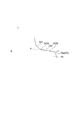
- FIG. 7 shows a graph representing the distribution of the outer diameter of the diffuser flow passage 8 in the circumferential direction and a graph representing the distribution of the inclination angle ⁇ in that case.
- the distribution in the circumferential direction of the distance R is made to have a minimum value or a minimum value within the range of the central angle ⁇ of 30 ° to 210 °.
- the cross section of the scroll passage 5 is positioned radially inward compared with the other portions although the position of the outlet of the diffuser passage 8 is the same. It is supposed to Then, since the inclination of the tangential direction A of the portion 5a1 becomes closer to the horizontal direction, the inclination angle ⁇ becomes smaller.
- FIG. 8 shows a graph representing the distribution of the distance R in the circumferential direction and a graph representing the distribution of the inclination angle ⁇ in that case.
- the distance from the axis of rotation L to scroll center O S of the scroll passage 5 R ( Combining FIG. 2) with locally reducing in the circumferential direction. If each of them is performed alone, the outer diameter of the diffuser flow passage 8 becomes locally large or the distance R becomes locally small, which makes manufacturing difficult and adversely affects the flow of compressed air. There is a possibility of giving. However, by combining the two, it is possible to moderate local changes in the outer diameter of the diffuser flow passage 8 and the distance R.
- the second flow path wall 7 b is connected to the flat end face 22 vertically connected to the flat inner wall surface 21 and the end face 22 and has a convex shape curved in a convex shape with respect to the scroll flow path 5.
- the inner wall surface 23 and the concave inner wall surface 24 which is connected to the convex inner wall surface 23 and is concavely curved with respect to the scroll passage 5 are provided, but the present invention is not limited to this configuration.
- the end face 22 may not be perpendicular to the flat inner wall 21 or may be curved rather than flat. Further, the concave inner wall surface 24 and the end surface 22 may be connected without the convex inner wall surface 23.
- FIG. 9 exemplarily shows the case where the concave inner wall 24 includes two concave inner walls.
- the two concave inner wall surfaces constitute a first concave circular arc portion 241 and a second concave circular arc portion 242, respectively.
- the second concave arc portion 242 has a radially inner end 242a and a radially outer end 242b, the end 242a is connected to the first concave arc portion 241, and the end 242b is a convex arc portion 23a. It is connected to the.
- the inclination angle ⁇ is perpendicular to the tangential direction A of the radially outer end 242 b of the concave arc portion located outermost in the radial direction, ie, the second concave arc portion 242, and the rotation axis L It is the angle that makes with the direction B.
- the distribution of the inclination angle ⁇ has the minimum value or the minimum value in the range of the central angle ⁇ from 30 ° to 210 °, but the range of the central angle ⁇ from 30 ° to 120 ° It may have a local minimum or a minimum (see FIG. 6).
- the flow passage area of the scroll flow passage 5 decreases from the outlet side toward the tongue 4 a. Due to such a shape of the scroll channel 5, the inclination angle ⁇ (see FIG. 5) of the concave arc portion 24a (see FIG. 5) tends to be larger as it is closer to the tongue 4a.
- the inclination angle ⁇ has a minimum value or a minimum value in the range of a central angle from 30 ° to 120 ° where the inclination angle ⁇ tends to increase.
- the inclination angle ⁇ can be reduced in the range of the central angle from 30 ° to 210 °, so that the swirl flow f 2 and the diffuser channel 8 are discharged. is further suppressed interference with the flow f 3 of the compressed fluid, the occurrence of peeling in the scroll passage 8 is further reduced. As a result, the efficiency of the centrifugal compressor 1 at the small flow rate operating point can be improved.
- the diffuser flow passage 8 is usually formed by cutting
- the diffuser inner flow passage 21 is defined by the flat inner wall surface 21 defining the diffuser flow passage 8 being perpendicular to the rotation axis L and flat. Can be easily processed.
Abstract
少なくとも1つの凹状円弧部分のうちインペラの半径方向において最も外側の凹状円弧部分のインペラの半径方向外側の端縁の接線方向と、回転軸線と垂直な方向とのなす傾斜角度は、スクロール流路の周方向に沿って分布を有し、スクロール部の舌部からスクロール流路の出口に向かうスクロール流路内の周方向位置を舌部を基準として回転軸線を中心とする中心角で表すと、傾斜角度の分布は、30°から210°までの中心角の範囲内に極小値又は最小値を有する。
Description
本開示は、遠心圧縮機及びこの遠心圧縮機を備えたターボチャージャに関する。
近年、遠心圧縮機の作動領域の拡大が求められている。例えば、自動車エンジンでは、低速度領域における燃費改善・加速度性能向上が求められており、これに伴い、ターボチャージャにも低速・小流量作動点の効率向上が求められている。このような作動領域は、ターボチャージャの遠心圧縮機が失速状態で作動する領域であり、この領域では、スクロール流路内における大規模な剥離の発生が確認される。特許文献1には、スクロール流路において巻き終わりから巻き始めへの再循環流を要因とする剥離の発生が記載されている。
しかしながら、本発明者らの鋭意検討の結果、特許文献1に記載された再循環流とは別の要因による剥離の発生が明らかになった。すなわち、スクロール流路が形成されたスクロール部の舌部付近でディフューザ流路から排出される圧縮空気は、スクロール流路の内壁面に沿って旋回しながらスクロール流路を流通し、このような旋回流れがスクロール流路の内壁面に沿ってちょうど一周したあたりで、ディフューザ流路から排出される圧縮空気と干渉する。これがスクロール流路内の剥離の要因の1つとなる。
上述の事情に鑑みて、本開示の少なくとも1つの実施形態は、小流量作動点における効率を向上した遠心圧縮機及びこの遠心圧縮機を備えたターボチャージャを提供することを目的とする。
(1)本開示の少なくとも1つの実施形態に係る遠心圧縮機は、
インペラ及びハウジングを備える遠心圧縮機であって、
前記ハウジングは、
前記インペラの外周側に渦巻き状のスクロール流路が形成されたスクロール部と、
前記インペラの回転軸線の延びる方向に間隔をあけて設けられた一対の流路壁を含み、前記インペラの半径方向内側で前記スクロール流路の周方向に沿って前記スクロール流路と連通するディフューザ流路を前記一対の流路壁間に形成するディフューザ部と
を含み、
前記一対の流路壁は、
第1流路壁と、
前記回転軸線の延びる方向において前記第1流路壁に対して前記スクロール流路のスクロール中心側に位置する第2流路壁と
を有し、
前記第2流路壁は、前記スクロール流路の内壁面のうち前記半径方向内側に位置する内壁面の一部を含み、前記第2流路壁が含む前記内壁面は、前記回転軸線を含む平面による前記ハウジングの断面において、前記スクロール流路内に曲率半径を有する少なくとも1つの凹状円弧部分を構成し、
前記少なくとも1つの凹状円弧部分のうち前記インペラの半径方向において最も外側の凹状円弧部分の前記インペラの半径方向外側の端縁の接線方向と、前記回転軸線と垂直な方向とのなす傾斜角度は、前記スクロール流路の周方向に沿って分布を有し、
前記スクロール部の舌部から前記スクロール流路の出口に向かう前記スクロール流路内の周方向位置を前記舌部を基準として前記回転軸線を中心とする中心角で表すと、前記傾斜角度の前記分布は、30°から210°までの前記中心角の範囲内に極小値又は最小値を有する。
上記(1)の構成によると、スクロール流路内をスクロール流路の内壁面に沿って旋回しながら流通する旋回流れがスクロール流路の内壁面に沿ってちょうど一周したあたりで、旋回流れの方向と、ディフューザ流路から排出される圧縮流体の流れ方向とのなす角度が小さくなるので、旋回流れとディフューザ流路から排出される圧縮流体の流れとの干渉が抑制されて、スクロール流路内における剥離の発生が低減される。その結果、小流量作動点における遠心圧縮機の効率を向上することができる。
(2)いくつかの実施形態では、上記(1)の構成において、
前記傾斜角度の前記分布は、30°から120°までの前記中心角の範囲内に極小値又は最小値を有する。
前記傾斜角度の前記分布は、30°から120°までの前記中心角の範囲内に極小値又は最小値を有する。
スクロール流路の流路面積は、出口側から舌部に向かって小さくなる。このようなスクロール流路の形状のために、舌部に近いほど凹状円弧部分の傾斜角度が大きくなる傾向がある。上記(2)の構成によると、この傾斜角度の大きさを意識せずにスクロール流路を形成するとこの傾斜角度が大きくなる傾向のある30°から120°までの中心角の範囲でこの傾斜角度が極小値又は最小値を有するようにスクロール流路を形成することで、30°から210°までの中心角の範囲でこの傾斜角度を小さくすることができるので、旋回流れとディフューザ流路から排出される圧縮流体の流れとの干渉がより抑制されて、スクロール流路内における剥離の発生がより低減される。その結果、小流量作動点における遠心圧縮機の効率を向上することができる。
(3)いくつかの実施形態では、上記(1)または(2)の構成において、
前記第2流路壁は、
前記ディフューザ流路を画定するとともに前記回転軸線と垂直かつ平坦な平坦内壁面と、
前記スクロール流路を画定するとともに前記スクロール流路に対して凸状に湾曲した凸状内壁面と、
前記スクロール流路を画定するとともに前記回転軸線を含む平面による前記ハウジングの断面において前記少なくとも1つの凹状円弧部分を構成する少なくとも1つの凹状内壁面であって、該少なくとも1つの凹状内壁面のうち前記インペラの半径方向において最も外側の凹状内壁面が前記凸状円弧部分に接続される少なくとも1つの凹状内壁面と、
前記インペラの半径方向において前記平坦内壁面の最も外側で前記平坦内壁面と前記凸状内壁面とを接続する端面と
を含む。
上記(3)の構成によると、旋回流れとディフューザ流路から排出される圧縮流体の流れとの干渉を抑制して、スクロール流路内における剥離の発生を低減できるとともに、ディフューザ流路を画定する内壁が回転軸線と垂直かつ平坦であることにより、ディフューザ流路の加工を容易にすることもできる。
(4)いくつかの実施形態では、上記(1)~(3)のいずれかの構成において、
前記回転軸線を中心とする前記ディフューザ流路の外径は前記ディフューザ流路の周方向に分布を有し、前記ディフューザ流路の外径の前記分布は、30°から210°までの前記中心角の範囲内に極大値又は最大値を有する。
前記回転軸線を中心とする前記ディフューザ流路の外径は前記ディフューザ流路の周方向に分布を有し、前記ディフューザ流路の外径の前記分布は、30°から210°までの前記中心角の範囲内に極大値又は最大値を有する。
上記(4)の構成によると、30°から210°までの中心角の範囲で、凹状円弧部分の傾斜角度を極小又は最小にすることができるので、旋回流れとディフューザ流路から排出される圧縮流体の流れとの干渉が抑制されて、スクロール流路内における剥離の発生が低減される。その結果、小流量作動点における遠心圧縮機の効率を向上することができる。
(5)いくつかの実施形態では、上記(1)~(4)のいずれかの構成において、
前記回転軸線から前記スクロール流路のスクロール中心までの距離は前記スクロール流路の周方向に分布を有し、前記距離の前記分布は、30°から210°までの前記中心角の範囲内に極小値又は最小値を有する。
前記回転軸線から前記スクロール流路のスクロール中心までの距離は前記スクロール流路の周方向に分布を有し、前記距離の前記分布は、30°から210°までの前記中心角の範囲内に極小値又は最小値を有する。
上記(5)の構成によると、30°から210°までの中心角の範囲で、凹状円弧部分の傾斜角度を極小又は最小にすることができるので、旋回流れとディフューザ流路から排出される圧縮流体の流れとの干渉が抑制されて、スクロール流路内における剥離の発生が低減される。その結果、小流量作動点における遠心圧縮機の効率を向上することができる。
(6)本開示の少なくとも1つの実施形態に係るターボチャージャは、
上記(1)~(5)のいずれかの遠心圧縮機を備える。
上記(1)~(5)のいずれかの遠心圧縮機を備える。
上記(6)の構成によると、スクロール流路内における剥離の発生が低減されるので、低速・小流量作動点におけるターボチャージャの効率を向上することができる。
本開示の少なくとも1つの実施形態によれば、スクロール流路内をスクロール流路の内壁面に沿って旋回しながら流通する旋回流れがスクロール流路の内壁面に沿ってちょうど一周したあたりで、旋回流れの方向と、ディフューザ流路から排出される圧縮流体の流れ方向とのなす角度が小さくなるので、旋回流れとディフューザ流路から排出される圧縮流体の流れとの干渉が抑制されて、スクロール流路内における剥離の発生が低減される。その結果、小流量作動点における遠心圧縮機の効率を向上することができる。
以下、添付図面を参照して本発明のいくつかの実施形態について説明する。ただし、本発明の範囲は以下の実施形態に限定されるものではない。以下の実施形態に記載されている構成部品の寸法、材質、形状、その相対配置などは、本発明の範囲をそれにのみ限定する趣旨ではなく、単なる説明例に過ぎない。
本開示の一実施形態に係る遠心圧縮機を、ターボチャージャの遠心圧縮機を例にして説明する。ただし、本開示における遠心圧縮機は、ターボチャージャの遠心圧縮機に限定するものではなく、単独で動作する任意の遠心圧縮機であってもよい。以下の説明において、この圧縮機によって圧縮される流体は空気であるが、任意の流体に置き換えることが可能である。
図1に示されるように、遠心圧縮機1は、ハウジング2と、ハウジング2内で回転軸線Lを中心に回転可能に設けられたインペラ3とを備えている。図2に示されるように、ハウジング2は、インペラ3の外周側に渦巻き状のスクロール流路5が形成されたスクロール部4と、回転軸線Lの延びる方向に間隔をあけて設けられた一対の流路壁7、すなわち第1流路壁7a及び第2流路壁7bを含むディフューザ部6と、円筒形状の空気入口部9とを有している。第2流路壁7bは、回転軸線Lの延びる方向において第1流路壁7aに対してスクロール流路5のスクロール中心OS側に位置している。第1流路壁7a及び第2流路壁7b間には、インペラ3の半径方向内側でスクロール流路5の周方向に沿ってスクロール流路5と連通するディフューザ流路8が形成されている。
空気入口部9を介して遠心圧縮機1内に流入した空気は、インペラ3によって圧縮されて圧縮空気となる。圧縮空気は、ディフューザ流路8を流通してスクロール流路5内に流入し、次いで、スクロール流路5を流通して遠心圧縮機1から排出される。
ターボチャージャが低速で作動するときのように、遠心圧縮機1に流入する空気量が小さい場合、遠心圧縮機1は失速状態で作動することになり効率が低下する。このような作動領域では、スクロール流路5内において大規模な剥離の発生が確認される。本発明者らは鋭意検討の結果、このような剥離が発生する要因の1つを見出した。その要因による剥離の発生原理を以下に説明する。
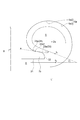
図1に示されるように、スクロール部4(図2参照)の舌部4aからスクロール流路5の出口に向かうスクロール流路5内の周方向位置を、舌部4aを基準として回転軸線Lを中心とする中心角θで表す。したがって、舌部4aの周方向位置を表す中心角θは0°となる。
図3に示されるように、舌部4a付近でディフューザ流路8から排出された圧縮空気の流れf1は、スクロール流路5の内壁面に沿って旋回しながらスクロール流路5を流通する。このような圧縮空気の旋回流れf2がスクロール流路5の内壁面に沿ってちょうど一周したあたり(図3では中心角θ=30°付近)で、ディフューザ流路8から排出される圧縮空気f3と干渉する。この干渉がスクロール流路5内の剥離の要因の1つとなる。
図4(a)に示されるように、回転軸線Lを含むハウジング2(図2参照)の断面において、スクロール流路5の内壁面5aのうち第2流路壁7bと接続する部分5a1の接線方向Aと、回転軸線Lと垂直な方向Bとのなす傾斜角度αが大きいほど、すなわち90°に近いほど、図4(b)に示されるように、スクロール流路5の内壁面5aに沿って流通する圧縮空気の旋回流れf2と、ディフューザ流路8から排出される圧縮空気の流れf3とのなす角度βが大きくなる。そうすると、ディフューザ流路8からスクロール流路5内に流入しようとする圧縮空気の流れf3を旋回流れf2が塞ぐように干渉するので、この干渉が発生する部分で剥離が生じるようになる。
そこで、このような干渉の発生を抑制するためには、傾斜角度αが小さくなるようなスクロール流路5の断面形状が必要になる。傾斜角度αを小さくしたスクロール流路5の断面形状の例を図5に示す。第2流路壁7bは、ディフューザ流路8を画定するとともに回転軸線Lと垂直かつ平坦な平坦内壁面21と、平坦内壁面21の最も半径方向外側で平坦内壁面21と垂直に接続される平坦な端面22と、端面22に接続されるとともにスクロール流路5に対して凸状に湾曲した凸状内壁面23と、凸状内壁面23に接続されるとともにスクロール流路5に対して凹状に湾曲した凹状内壁面24とを有している。ここで、スクロール中心OSを通り回転軸線Lに平行な仮想線L’を想定し、スクロール流路5の内壁面5aを、仮想線L’に対して半径方向内側の部分5a2と半径方向外側の部分5a3とに区別する。端面22と凸状内壁面23と凹状内壁面24とは、内壁面5aの部分5a2の一部である。
尚、スクロール流路5に対して凸状に湾曲することは、回転軸線Lを含むハウジング2(図2参照)の断面において凸状内壁面23が構成する凸状円弧部分23aの曲率中心がスクロール流路5の外部に位置することを意味し、スクロール流路5に対して凹状に湾曲することは、回転軸線Lを含むハウジング2の断面において凹状内壁面24が構成する凹状円弧部分24aの曲率中心がスクロール流路5の内部に位置することを意味する。
回転軸線Lを含むハウジング2の断面において、凹状円弧部分24aの半径方向外側の端縁24a1の接線方向Aと、回転軸線Lと垂直な方向Bとのなす傾斜角度αが小さくなると、旋回流れf2と、ディフューザ流路8からスクロール流路5内に流入しようとする圧縮空気の流れf3とのなす角度βが小さくなる。そうすると、旋回流れf2と圧縮空気の流れf3との干渉が抑制されるので、剥離の発生が低減される。したがって、スクロール流路5の断面形状を、このような干渉が発生する部分において傾斜角度αが小さくなるような形状にすることによって、剥離の発生を低減することができる。
また、本発明者らは、CFD解析を行うことによって、30°から210°までの中心角θの範囲内で剥離が発生しやすいという結果を得た。これは、スクロール流路5内で安定した旋回流れが形成されると、スクロール流路5内の旋回流れと、ディフューザ流路8から排出される圧縮空気の流れとは徐々に干渉しなくなることから、このような干渉はスクロール流路5において上流側ほど発生しやすいためである。したがって、スクロール流路5の断面形状を、上流側において傾斜角度αが小さくなるような形状とすることにより、剥離の発生を有効に低減することができる。
図5に示されるスクロール流路5の断面形状は、ハウジング2(図2参照)の一断面における形状である。スクロール流路5の断面形状は、実際は周方向に従って変化する。したがって、周方向に従って傾斜角度αは変化する。すなわち、傾斜角度αは、スクロール流路5の周方向に沿って分布を有する。そこで、本発明者が得た上記知見から、図6に示されるように、中心角θが30°から210°までの範囲となるスクロール流路5の周方向位置の範囲において、傾斜角度αの分布が最小値を有することにより、剥離の発生を有効に低減することができる。尚、傾斜角度αの分布が上記範囲内で最小値を有するのではなく、30°から210°までの中心角θの範囲内での最小値、すなわち極小値を有するような分布であってもよい。言い換えると、210°以降の中心角θの範囲内で、傾斜角度αの分布は、極小値よりも小さい値を有してもよい。
次に、傾斜角度αの分布が、30°から210°までの中心角θの範囲内で極小値又は最小値をとるようにするための、ハウジング2(図2参照)の構成のいくつかの実施形態を説明する。
一実施形態では、ディフューザ流路8(図1参照)の外径を周方向に局所的に大きくする。すなわち、ディフューザ流路8の外径の周方向の分布を、30°から210°までの中心角θの範囲内で極大値又は最大値をとるようにする。図5を参照すると、ディフューザ流路8の外径が局所的に大きい部分では、第2流路壁7bの端面22の位置が他の部分に比べて、より半径方向外側に位置するようになっている。そうすると、凹状内壁面24の半径方向の幅を大きくすることができるので、部分5a1の接線方向Aの傾きがより水平方向に近くなり、傾斜角度αが小さくなる。
図7に、ディフューザ流路8の外径の周方向の分布を表すグラフと、その場合の傾斜角度αの分布を表すグラフとを示す。30°から210°までの中心角θの範囲内でディフューザ流路8の外径が最大になるような構成にすると、30°から210°までの中心角θの範囲内で傾斜角度αが最小値をとるようになる。この範囲内で傾斜角度αが最小値ではなく極小値をとる場合には、30°から210°までの中心角θの範囲内でディフューザ流路8の外径が極大になるような構成にすればよい。
また、他の実施形態では、回転軸線Lからスクロール流路5のスクロール中心OSまでの距離R(図2参照)を周方向に局所的に小さくする。すなわち、距離Rの周方向の分布を、30°から210°までの中心角θの範囲内で極小値又は最小値をとるようにする。図5を参照すると、距離Rが局所的に小さい部分では、他の部分に比べて、ディフューザ流路8の出口の位置が同じあるにも関わらずスクロール流路5の断面が半径方向内側に位置するようになっている。そうすると、部分5a1の接線方向Aの傾きがより水平方向に近くなるので、傾斜角度αが小さくなる。
図8に、距離Rの周方向の分布を表すグラフと、その場合の傾斜角度αの分布を表すグラフとを示す。30°から210°までの中心角θの範囲内で距離Rが最小になるような構成にすると、30°から210°までの中心角θの範囲内で傾斜角度αが最小値をとるようになる。この範囲内で傾斜角度αが最小値ではなく極小値をとる場合には、30°から210°までの中心角θの範囲内で距離Rが極小になるような構成にすればよい。
さらに、他の実施形態では、ディフューザ流路8(図1参照)の外径を周方向に局所的に大きくすることと、回転軸線Lからスクロール流路5のスクロール中心OSまでの距離R(図2参照)を周方向に局所的に小さくすることとを組み合わせる。それぞれを単独で行うと、ディフューザ流路8の外径が局所的に大きくなりすぎたり、距離Rが局所的に小さくなりすぎたりすることにより、製造が難しくなったり、圧縮空気の流れに悪影響を与える可能性がある。しかし、両者を組み合わせることにより、ディフューザ流路8の外径及び距離Rの局所的な変化を緩やかにすることができる。
このように、スクロール流路5内をスクロール流路5の内壁面5aに沿って旋回しながら流通する旋回流れf2がスクロール流路5の内壁面5aに沿ってちょうど一周したあたりで、旋回流れf2の方向と、ディフューザ流路8から排出される圧縮流体の流れf3の方向とのなす角度βが小さくなるので、旋回流れf2とディフューザ流路から排出される圧縮流体の流れf3との干渉が抑制されて、スクロール流路5内における剥離の発生が低減される。その結果、小流量作動点における遠心圧縮機1の効率を向上することができる。
上記実施形態では、第2流路壁7bは、平坦内壁面21と垂直に接続される平坦な端面22と、端面22に接続されるとともにスクロール流路5に対して凸状に湾曲した凸状内壁面23と、凸状内壁面23に接続されるとともにスクロール流路5に対して凹状に湾曲した凹状内壁面24とを有しているが、この形態に限定するものではない。端面22が平坦内壁面21と垂直ではなかったり、平坦ではなく湾曲していたりしてもよい。また、凸状内壁面23がなく、凹状内壁面24と端面22とが接続されていてもよい。
また、凹状内壁面24が2つ以上あってもよい。図9に、凹状内壁面24が、2つの凹状内壁面を含む場合を例示的に示す。回転軸線Lを含むハウジング2(図2参照)の断面において、2つの凹状内壁面がそれぞれ、第1凹状円弧部分241と第2凹状円弧部分242とを構成している。第2凹状円弧部分242は、半径方向内側の端縁242a及び半径方向外側の端縁242bを有し、端縁242aは第1凹状円弧部分241に接続され、端縁242bは凸状円弧部分23aに接続されている。このような形態の場合、傾斜角度αは、最も半径方向外側に位置する凹状円弧部分、すなわち第2凹状円弧部分242の半径方向外側の端縁242bの接線方向Aと、回転軸線Lと垂直な方向Bとのなす角度となる。
上記実施形態では、傾斜角度αの分布は、30°から210°までの中心角θの範囲内に極小値又は最小値を有していたが、30°から120°までの中心角θの範囲内に極小値又は最小値を有していてもよい(図6参照)。図1に示されるように、スクロール流路5の流路面積は、出口側から舌部4aに向かって小さくなる。このようなスクロール流路5の形状のために、舌部4aに近いほど凹状円弧部分24a(図5参照)の傾斜角度α(図5参照)が大きくなる傾向がある。この傾斜角度αの大きさを意識せずにスクロール流路5を形成するとこの傾斜角度αが大きくなる傾向のある30°から120°までの中心角の範囲でこの傾斜角度αが極小値又は最小値を有するようにスクロール流路5を形成することで、30°から210°までの中心角の範囲でこの傾斜角度αを小さくすることができるので、旋回流れf2とディフューザ流路8から排出される圧縮流体の流れf3との干渉がより抑制されて、スクロール流路8内における剥離の発生がより低減される。その結果、小流量作動点における遠心圧縮機1の効率を向上することができる。
また、ディフューザ流路8は通常、切削加工により形成されるが、上記実施形態では、ディフューザ流路8を画定する平坦内壁面21が回転軸線Lと垂直かつ平坦であることより、ディフューザ流路8を容易に加工することができるようになる。
1 遠心圧縮機
2 ハウジング
3 インペラ
4 スクロール部
4a 舌部
5 スクロール流路
5a (スクロール流路の)内壁面
5a1 (内壁面の)部分
5a2 (内壁面の)半径方向内側の部分
5a3 (内壁面の)半径方向外側の部分
6 ディフューザ部
7 流路壁
7a 第1流路壁
7b 第2流路壁
8 ディフューザ流路
9 空気入口部
21 平坦内壁面
22 端面
23 凸状内壁面
23a 凸状円弧部分
24 凹状内壁面
24a 凹状円弧部分
24a1 (凹状円弧部分の)端縁
241 第1凹状円弧部分
242 第2凹状円弧部分
242a (第2凹状円弧部分の)端縁
242b (第2凹状円弧部分の)端縁
A 接線方向
B 回転軸線と垂直な方向
L (インペラの)回転軸線
L’ 仮想線
Os スクロール中心
α 傾斜角度
β 角度
θ 中心角
f1 舌部付近でディフューザ流路から排出される圧縮空気の流れ
f2 旋回流れ
f3 ディフューザ流路から排出される圧縮空気の流れ
Claims (6)
- インペラ及びハウジングを備える遠心圧縮機であって、
前記ハウジングは、
前記インペラの外周側に渦巻き状のスクロール流路が形成されたスクロール部と、
前記インペラの回転軸線の延びる方向に間隔をあけて設けられた一対の流路壁を含み、前記インペラの半径方向内側で前記スクロール流路の周方向に沿って前記スクロール流路と連通するディフューザ流路を前記一対の流路壁間に形成するディフューザ部と
を含み、
前記一対の流路壁は、
第1流路壁と、
前記回転軸線の延びる方向において前記第1流路壁に対して前記スクロール流路のスクロール中心側に位置する第2流路壁と
を有し、
前記第2流路壁は、前記スクロール流路の内壁面のうち前記半径方向内側に位置する内壁面の一部を含み、前記第2流路壁が含む前記内壁面は、前記回転軸線を含む平面による前記ハウジングの断面において、前記スクロール流路内に曲率半径を有する少なくとも1つの凹状円弧部分を構成し、
前記少なくとも1つの凹状円弧部分のうち前記インペラの半径方向において最も外側の凹状円弧部分の前記インペラの半径方向外側の端縁の接線方向と、前記回転軸線と垂直な方向とのなす傾斜角度は、前記スクロール流路の周方向に沿って分布を有し、
前記スクロール部の舌部から前記スクロール流路の出口に向かう前記スクロール流路内の周方向位置を前記舌部を基準として前記回転軸線を中心とする中心角で表すと、前記傾斜角度の前記分布は、30°から210°までの前記中心角の範囲内に極小値又は最小値を有する遠心圧縮機。 - 前記傾斜角度の前記分布は、30°から120°までの前記中心角の範囲内に極小値又は最小値を有する、請求項1に記載の遠心圧縮機。
- 前記第2流路壁は、
前記ディフューザ流路を画定するとともに前記回転軸線と垂直かつ平坦な平坦内壁面と、
前記スクロール流路を画定するとともに前記スクロール流路に対して凸状に湾曲した凸状内壁面と、
前記スクロール流路を画定するとともに前記回転軸線を含む平面による前記ハウジングの断面において前記少なくとも1つの凹状円弧部分を構成する少なくとも1つの凹状内壁面であって、該少なくとも1つの凹状内壁面のうち前記インペラの半径方向において最も外側の凹状内壁面が前記凸状円弧部分に接続される少なくとも1つの凹状内壁面と、
前記インペラの半径方向において前記平坦内壁面の最も外側で前記平坦内壁面と前記凸状内壁面とを接続する端面と
を含む、請求項1または2に記載の遠心圧縮機。 - 前記回転軸線を中心とする前記ディフューザ流路の外径は前記ディフューザ流路の周方向に分布を有し、前記ディフューザ流路の外径の前記分布は、30°から210°までの前記中心角の範囲内に極大値又は最大値を有する、請求項1~3のいずれか一項に記載の遠心圧縮機。
- 前記回転軸線から前記スクロール流路のスクロール中心までの距離は前記スクロール流路の周方向に分布を有し、前記距離の前記分布は、30°から210°までの前記中心角の範囲内に極小値又は最小値を有する、請求項1~4のいずれか一項に記載の遠心圧縮機。
- 請求項1~5のいずれか一項に記載の遠心圧縮機を備えたターボチャージャ。
Priority Applications (5)
| Application Number | Priority Date | Filing Date | Title |
|---|---|---|---|
| US16/605,454 US11073164B2 (en) | 2017-11-06 | 2017-11-06 | Centrifugal compressor and turbocharger including the same |
| PCT/JP2017/039909 WO2019087385A1 (ja) | 2017-11-06 | 2017-11-06 | 遠心圧縮機及びこの遠心圧縮機を備えたターボチャージャ |
| JP2019550120A JP6842564B2 (ja) | 2017-11-06 | 2017-11-06 | 遠心圧縮機及びこの遠心圧縮機を備えたターボチャージャ |
| CN201780090061.3A CN110573748B (zh) | 2017-11-06 | 2017-11-06 | 离心压缩机以及具备该离心压缩机的涡轮增压器 |
| EP17930425.8A EP3708848A4 (en) | 2017-11-06 | 2017-11-06 | CENTRIFUGAL COMPRESSOR AND TURBOCHARGER INCLUDING LEDIT CENTRIFUGAL COMPRESSOR |
Applications Claiming Priority (1)
| Application Number | Priority Date | Filing Date | Title |
|---|---|---|---|
| PCT/JP2017/039909 WO2019087385A1 (ja) | 2017-11-06 | 2017-11-06 | 遠心圧縮機及びこの遠心圧縮機を備えたターボチャージャ |
Publications (1)
| Publication Number | Publication Date |
|---|---|
| WO2019087385A1 true WO2019087385A1 (ja) | 2019-05-09 |
Family
ID=66331524
Family Applications (1)
| Application Number | Title | Priority Date | Filing Date |
|---|---|---|---|
| PCT/JP2017/039909 WO2019087385A1 (ja) | 2017-11-06 | 2017-11-06 | 遠心圧縮機及びこの遠心圧縮機を備えたターボチャージャ |
Country Status (5)
| Country | Link |
|---|---|
| US (1) | US11073164B2 (ja) |
| EP (1) | EP3708848A4 (ja) |
| JP (1) | JP6842564B2 (ja) |
| CN (1) | CN110573748B (ja) |
| WO (1) | WO2019087385A1 (ja) |
Cited By (1)
| Publication number | Priority date | Publication date | Assignee | Title |
|---|---|---|---|---|
| JPWO2020240775A1 (ja) * | 2019-05-30 | 2020-12-03 |
Families Citing this family (3)
| Publication number | Priority date | Publication date | Assignee | Title |
|---|---|---|---|---|
| US20230049412A1 (en) * | 2020-04-17 | 2023-02-16 | Mitsubishi Heavy Industries Engine & Turbocharger, Ltd. | Scroll casing and centrifugal compressor |
| DE112021003609T5 (de) * | 2020-12-09 | 2023-04-27 | Ihi Corporation | Radialverdichter und Turbolader |
| CN114857088A (zh) * | 2022-05-30 | 2022-08-05 | 杭州老板电器股份有限公司 | 一种吸油烟机 |
Citations (5)
| Publication number | Priority date | Publication date | Assignee | Title |
|---|---|---|---|---|
| JP2010216378A (ja) * | 2009-03-17 | 2010-09-30 | Kobe Steel Ltd | ターボ圧縮機 |
| WO2012090853A1 (ja) * | 2010-12-27 | 2012-07-05 | 三菱重工業株式会社 | 遠心圧縮機のスクロール構造 |
| JP2012193716A (ja) * | 2011-03-17 | 2012-10-11 | Mitsubishi Heavy Ind Ltd | 遠心圧縮機のスクロール構造 |
| JP2016017419A (ja) * | 2014-07-07 | 2016-02-01 | トヨタ自動車株式会社 | 過給機 |
| WO2017109949A1 (ja) | 2015-12-25 | 2017-06-29 | 三菱重工業株式会社 | 遠心圧縮機及びターボチャージャ |
Family Cites Families (5)
| Publication number | Priority date | Publication date | Assignee | Title |
|---|---|---|---|---|
| JP2005188337A (ja) * | 2003-12-25 | 2005-07-14 | Toyota Motor Corp | 作動流体還流路を有する過給用コンプレッサ |
| DE102007034236A1 (de) | 2007-07-23 | 2009-02-05 | Continental Automotive Gmbh | Radialverdichter mit einem Diffusor für den Einsatz bei einem Turbolader |
| JP5479316B2 (ja) * | 2010-12-28 | 2014-04-23 | 三菱重工業株式会社 | 遠心圧縮機のスクロール構造 |
| JP5439423B2 (ja) * | 2011-03-25 | 2014-03-12 | 三菱重工業株式会社 | 遠心圧縮機のスクロール形状 |
| WO2017098911A1 (ja) * | 2015-12-10 | 2017-06-15 | 株式会社Ihi | 遠心圧縮機の吐出部構造 |
-
2017
- 2017-11-06 CN CN201780090061.3A patent/CN110573748B/zh active Active
- 2017-11-06 WO PCT/JP2017/039909 patent/WO2019087385A1/ja unknown
- 2017-11-06 JP JP2019550120A patent/JP6842564B2/ja active Active
- 2017-11-06 EP EP17930425.8A patent/EP3708848A4/en active Pending
- 2017-11-06 US US16/605,454 patent/US11073164B2/en active Active
Patent Citations (5)
| Publication number | Priority date | Publication date | Assignee | Title |
|---|---|---|---|---|
| JP2010216378A (ja) * | 2009-03-17 | 2010-09-30 | Kobe Steel Ltd | ターボ圧縮機 |
| WO2012090853A1 (ja) * | 2010-12-27 | 2012-07-05 | 三菱重工業株式会社 | 遠心圧縮機のスクロール構造 |
| JP2012193716A (ja) * | 2011-03-17 | 2012-10-11 | Mitsubishi Heavy Ind Ltd | 遠心圧縮機のスクロール構造 |
| JP2016017419A (ja) * | 2014-07-07 | 2016-02-01 | トヨタ自動車株式会社 | 過給機 |
| WO2017109949A1 (ja) | 2015-12-25 | 2017-06-29 | 三菱重工業株式会社 | 遠心圧縮機及びターボチャージャ |
Non-Patent Citations (1)
| Title |
|---|
| See also references of EP3708848A4 * |
Cited By (4)
| Publication number | Priority date | Publication date | Assignee | Title |
|---|---|---|---|---|
| JPWO2020240775A1 (ja) * | 2019-05-30 | 2020-12-03 | ||
| WO2020240775A1 (ja) * | 2019-05-30 | 2020-12-03 | 三菱重工エンジン&ターボチャージャ株式会社 | 遠心圧縮機及びターボチャージャ |
| JP7138242B2 (ja) | 2019-05-30 | 2022-09-15 | 三菱重工エンジン&ターボチャージャ株式会社 | 遠心圧縮機及びターボチャージャ |
| US11795969B2 (en) | 2019-05-30 | 2023-10-24 | Mitsubishi Heavy Industries Engine & Turbocharger, Ltd. | Centrifugal compressor and turbocharger |
Also Published As
| Publication number | Publication date |
|---|---|
| US20210123456A1 (en) | 2021-04-29 |
| JPWO2019087385A1 (ja) | 2020-04-23 |
| EP3708848A4 (en) | 2021-07-07 |
| CN110573748A (zh) | 2019-12-13 |
| JP6842564B2 (ja) | 2021-03-17 |
| EP3708848A1 (en) | 2020-09-16 |
| US11073164B2 (en) | 2021-07-27 |
| CN110573748B (zh) | 2021-06-01 |
Similar Documents
| Publication | Publication Date | Title |
|---|---|---|
| WO2019087385A1 (ja) | 遠心圧縮機及びこの遠心圧縮機を備えたターボチャージャ | |
| JP7082948B2 (ja) | 遠心圧縮機、ターボチャージャ | |
| WO2011013258A1 (ja) | 遠心圧縮機のインペラ | |
| CN108368856B (zh) | 离心压缩机的排出部构造 | |
| CN108700089B (zh) | 离心压缩机以及涡轮增压器 | |
| JP2008075536A (ja) | 遠心圧縮機 | |
| JP2008128064A (ja) | 斜流タービンまたはラジアルタービン | |
| JP2012193716A (ja) | 遠心圧縮機のスクロール構造 | |
| US11209015B2 (en) | Centrifugal compressor | |
| CN108700090B (zh) | 压缩机涡旋及离心压缩机 | |
| US11187242B2 (en) | Multi-stage centrifugal compressor | |
| US11905969B2 (en) | Scroll structure of centrifugal compressor and centrifugal compressor | |
| JP2014231844A (ja) | 渦巻ポンプ | |
| WO2021215471A1 (ja) | インペラ、及び遠心圧縮機 | |
| JPWO2019097611A1 (ja) | コンプレッサインペラ、コンプレッサ及びターボチャージャ | |
| JP7187542B2 (ja) | 遠心圧縮機及びこの遠心圧縮機を備えたターボチャージャ | |
| JP6876146B2 (ja) | 遠心圧縮機及びこの遠心圧縮機を備えたターボチャージャ | |
| JP7232332B2 (ja) | 遠心圧縮機のスクロール構造及び遠心圧縮機 | |
| JP2011111956A (ja) | 渦巻ポンプ | |
| JP7452708B2 (ja) | 遠心圧縮機および過給機 | |
| US11441428B2 (en) | Turbine blade and steam turbine including the same | |
| JP2012057489A (ja) | 遠心圧縮機のディフューザおよびこれを備えた遠心圧縮機 |
Legal Events
| Date | Code | Title | Description |
|---|---|---|---|
| 121 | Ep: the epo has been informed by wipo that ep was designated in this application |
Ref document number: 17930425 Country of ref document: EP Kind code of ref document: A1 |
|
| ENP | Entry into the national phase |
Ref document number: 2019550120 Country of ref document: JP Kind code of ref document: A |
|
| NENP | Non-entry into the national phase |
Ref country code: DE |
|
| ENP | Entry into the national phase |
Ref document number: 2017930425 Country of ref document: EP Effective date: 20200608 |