WO2019082723A1 - ズームレンズ系、及び撮像装置 - Google Patents
ズームレンズ系、及び撮像装置Info
- Publication number
- WO2019082723A1 WO2019082723A1 PCT/JP2018/038404 JP2018038404W WO2019082723A1 WO 2019082723 A1 WO2019082723 A1 WO 2019082723A1 JP 2018038404 W JP2018038404 W JP 2018038404W WO 2019082723 A1 WO2019082723 A1 WO 2019082723A1
- Authority
- WO
- WIPO (PCT)
- Prior art keywords
- lens
- lens group
- group
- image
- object side
- Prior art date
Links
Images


Classifications
-
- G—PHYSICS
- G02—OPTICS
- G02B—OPTICAL ELEMENTS, SYSTEMS OR APPARATUS
- G02B9/00—Optical objectives characterised both by the number of the components and their arrangements according to their sign, i.e. + or -
- G02B9/64—Optical objectives characterised both by the number of the components and their arrangements according to their sign, i.e. + or - having more than six components
-
- G—PHYSICS
- G02—OPTICS
- G02B—OPTICAL ELEMENTS, SYSTEMS OR APPARATUS
- G02B9/00—Optical objectives characterised both by the number of the components and their arrangements according to their sign, i.e. + or -
- G02B9/62—Optical objectives characterised both by the number of the components and their arrangements according to their sign, i.e. + or - having six components only
-
- G—PHYSICS
- G02—OPTICS
- G02B—OPTICAL ELEMENTS, SYSTEMS OR APPARATUS
- G02B13/00—Optical objectives specially designed for the purposes specified below
- G02B13/02—Telephoto objectives, i.e. systems of the type + - in which the distance from the front vertex to the image plane is less than the equivalent focal length
-
- G—PHYSICS
- G02—OPTICS
- G02B—OPTICAL ELEMENTS, SYSTEMS OR APPARATUS
- G02B13/00—Optical objectives specially designed for the purposes specified below
- G02B13/18—Optical objectives specially designed for the purposes specified below with lenses having one or more non-spherical faces, e.g. for reducing geometrical aberration
-
- G—PHYSICS
- G02—OPTICS
- G02B—OPTICAL ELEMENTS, SYSTEMS OR APPARATUS
- G02B15/00—Optical objectives with means for varying the magnification
- G02B15/14—Optical objectives with means for varying the magnification by axial movement of one or more lenses or groups of lenses relative to the image plane for continuously varying the equivalent focal length of the objective
- G02B15/146—Optical objectives with means for varying the magnification by axial movement of one or more lenses or groups of lenses relative to the image plane for continuously varying the equivalent focal length of the objective having more than five groups
- G02B15/1461—Optical objectives with means for varying the magnification by axial movement of one or more lenses or groups of lenses relative to the image plane for continuously varying the equivalent focal length of the objective having more than five groups the first group being positive
-
- G—PHYSICS
- G02—OPTICS
- G02B—OPTICAL ELEMENTS, SYSTEMS OR APPARATUS
- G02B15/00—Optical objectives with means for varying the magnification
- G02B15/14—Optical objectives with means for varying the magnification by axial movement of one or more lenses or groups of lenses relative to the image plane for continuously varying the equivalent focal length of the objective
- G02B15/16—Optical objectives with means for varying the magnification by axial movement of one or more lenses or groups of lenses relative to the image plane for continuously varying the equivalent focal length of the objective with interdependent non-linearly related movements between one lens or lens group, and another lens or lens group
- G02B15/20—Optical objectives with means for varying the magnification by axial movement of one or more lenses or groups of lenses relative to the image plane for continuously varying the equivalent focal length of the objective with interdependent non-linearly related movements between one lens or lens group, and another lens or lens group having an additional movable lens or lens group for varying the objective focal length
-
- G—PHYSICS
- G02—OPTICS
- G02B—OPTICAL ELEMENTS, SYSTEMS OR APPARATUS
- G02B27/00—Optical systems or apparatus not provided for by any of the groups G02B1/00 - G02B26/00, G02B30/00
- G02B27/0025—Optical systems or apparatus not provided for by any of the groups G02B1/00 - G02B26/00, G02B30/00 for optical correction, e.g. distorsion, aberration
-
- G—PHYSICS
- G02—OPTICS
- G02B—OPTICAL ELEMENTS, SYSTEMS OR APPARATUS
- G02B27/00—Optical systems or apparatus not provided for by any of the groups G02B1/00 - G02B26/00, G02B30/00
- G02B27/64—Imaging systems using optical elements for stabilisation of the lateral and angular position of the image
-
- G—PHYSICS
- G03—PHOTOGRAPHY; CINEMATOGRAPHY; ANALOGOUS TECHNIQUES USING WAVES OTHER THAN OPTICAL WAVES; ELECTROGRAPHY; HOLOGRAPHY
- G03B—APPARATUS OR ARRANGEMENTS FOR TAKING PHOTOGRAPHS OR FOR PROJECTING OR VIEWING THEM; APPARATUS OR ARRANGEMENTS EMPLOYING ANALOGOUS TECHNIQUES USING WAVES OTHER THAN OPTICAL WAVES; ACCESSORIES THEREFOR
- G03B5/00—Adjustment of optical system relative to image or object surface other than for focusing
-
- G—PHYSICS
- G02—OPTICS
- G02B—OPTICAL ELEMENTS, SYSTEMS OR APPARATUS
- G02B13/00—Optical objectives specially designed for the purposes specified below
- G02B13/001—Miniaturised objectives for electronic devices, e.g. portable telephones, webcams, PDAs, small digital cameras
- G02B13/009—Miniaturised objectives for electronic devices, e.g. portable telephones, webcams, PDAs, small digital cameras having zoom function
-
- G—PHYSICS
- G02—OPTICS
- G02B—OPTICAL ELEMENTS, SYSTEMS OR APPARATUS
- G02B15/00—Optical objectives with means for varying the magnification
- G02B15/14—Optical objectives with means for varying the magnification by axial movement of one or more lenses or groups of lenses relative to the image plane for continuously varying the equivalent focal length of the objective
- G02B15/16—Optical objectives with means for varying the magnification by axial movement of one or more lenses or groups of lenses relative to the image plane for continuously varying the equivalent focal length of the objective with interdependent non-linearly related movements between one lens or lens group, and another lens or lens group
-
- G—PHYSICS
- G02—OPTICS
- G02B—OPTICAL ELEMENTS, SYSTEMS OR APPARATUS
- G02B5/00—Optical elements other than lenses
- G02B5/005—Diaphragms
Definitions
- the present disclosure relates to a zoom lens system that is compact and can obtain good optical performance over the entire zoom range, and an imaging device using the zoom lens system.
- Patent Document 1 and Patent Document 2 disclose a zoom lens system which performs zooming by changing the distance between the groups, which is a six-group configuration capable of obtaining a high zoom ratio.
- the present disclosure is directed to a zoom lens that is compact and can provide good optical performance over the entire zoom range, and an imaging device using the zoom lens.
- the zoom lens system includes, in order from the object side to the image side, a first lens group having a positive power, a second lens group having a negative power, and a third lens group having a positive power; A fourth lens group having a negative power, a fifth lens group having a positive power, and a sixth lens group having a power.
- each group interval changes, and the fifth lens unit is configured of two or less lens elements.
- At least one convex meniscus lens element having a concave surface facing the object side and satisfying the following condition (4): 10.2 ⁇ fT / fW (4) where fT: telephoto end Focal length at fW: focal length at the wide angle end.
- a zoom lens that is compact and can provide good optical performance over the entire zoom range, and an imaging device using the zoom lens.
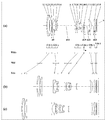
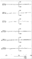
- Lens arrangement diagram showing an infinity in-focus condition of an imaging optical system according to Embodiment 1 (Numerical Example 1) Longitudinal aberration of the imaging optical system at infinity according to numerical example 1 Transverse aberration diagram in the basic state where image blur correction is not performed and in the state of image blur correction at the telephoto end of the imaging optical system according to Numerical Example 1.
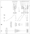
- Lens arrangement diagram showing an infinity in-focus condition of an imaging optical system according to Embodiment 2 (Numerical Example 2) Longitudinal aberration of the imaging optical system at infinity focusing state according to numerical example 2 Transverse aberration diagram in the basic state where image blur correction is not performed and in the state of image blur correction at the telephoto end of the imaging optical system according to Numerical Example 2.
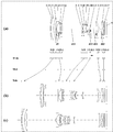
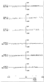
- Lens arrangement diagram showing an infinity in-focus condition of the imaging optical system according to Embodiment 3 (Numerical Example 3) Longitudinal aberration of infinity focusing state of imaging optical system according to Numerical Example 3 Transverse aberration diagram in the basic state in which image blur correction is not performed and in the image blur correction state at the telephoto end of the imaging optical system according to Numerical Example 3
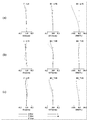
- Lens arrangement diagram showing an infinity in-focus condition of an imaging optical system according to Fourth Embodiment (Numerical Example 4) Longitudinal aberration diagram of in-focus condition of the imaging optical system according to Numerical Example 4 Transverse aberration diagram in the basic state in which image blur correction is not performed and in the image blur correction state at the telephoto end of the imaging optical system according to Numerical Example 4
- Lens arrangement diagram showing an infinity in-focus condition of an imaging optical system according to Embodiment 5 (Numerical Example 5) Longitudinal aberration of the imaging optical system at infinity according to numerical example 5 Transverse aberration diagram in the
- Embodiments 1 to 5 are lens arrangement diagrams of imaging optical systems according to Embodiments 1 to 5, respectively, each representing the imaging optical system in focus at infinity. There is.
- the part shown in (a) in the figure is the lens configuration at the wide angle end (shortest focal length state: focal length fW);
- the lens configuration at the position (intermediate focal length state: focal length fM ⁇ (fW * fT)) and the portion shown in (c) respectively represent the lens configuration at the telephoto end (longest focal length state: focal length fT).
- the aspect ratio is the same.
- the curved arrows provided between the part shown in (a) and the part shown in (b) in the drawing are wide-angle in order from the top It is a line obtained by connecting the positions of the lens units in each state of the end (Wide), the middle position (Mid), and the telephoto end (Tele). Between the wide angle end and the intermediate position, and between the intermediate position and the telephoto end, they are simply connected by a curve, which is different from the actual movement of each lens group.
- FIG. 1, FIG. 4, FIG. 7, FIG. 10, and FIG. 13 the arrows attached to the lens groups indicate focusing from an infinity in-focus condition to a close-point in-focus condition.
- FIGS. 1, 4, 7, 10, and 13 the reference numerals of the respective lens units are described below the positions of the respective lens units in the portion illustrated in (a) of the drawings, and thus for convenience.
- an arrow representing focusing is attached to the lower part of the reference numeral of each lens group, the direction in which each lens group moves in focusing in each zooming state will be specifically described later for each embodiment. .
- FIG. 1 FIG. 4, FIG. 7, FIG. 10, and FIG. 13, an asterisk (*) attached to a specific surface indicates that the surface is aspheric. Further, in FIG. 1, FIG. 4, FIG. 7, FIG. 10, and FIG. 13, the symbol (+) and the symbol (-) attached to the symbols of each lens group correspond to the symbols of the power of each lens group. In FIGS. 1, 4, 7, 10, and 13, the straight line described on the right side represents the position of the image plane S (the surface on the object side of the imaging device).
- FIG. 1 shows an imaging optical system according to the first embodiment.
- the zoom lens system includes, in order from the object side to the image side, a first lens group G1 having positive power, a second lens group G2 having negative power, and a third lens group G3 having positive power.
- the fourth lens group G4 having a negative power
- the fifth lens group G5 having a positive power
- the sixth lens group G6 having a negative power
- the parallel plate P the parallel plate P.
- the zoom lens system forms an image at the position of the image plane S.
- the first lens unit G1 includes, in order from the object side to the image side, a first lens element L1 having negative power, a second lens element L2 having positive power, and a third lens element L3 having positive power. Be done.
- the first lens element L1 and the second lens element L2 are cemented lenses bonded with an adhesive or the like.
- the second lens unit G2 includes, in order from the object side to the image side, a fourth lens element L4 having a negative power, a fifth lens element L5 having a negative power, and a sixth lens element L6 having a positive power. Be done.
- the third lens unit G3 includes, in order from the object side to the image side, an aperture A, a seventh lens element L7 having a positive power, an eighth lens element L8 having a positive power, and a ninth lens having a negative power.
- An element L9 is configured of a tenth lens element L10 having positive power.
- the eighth lens element L8 and the ninth lens element L9 are cemented lenses bonded with an adhesive or the like.
- the fourth lens unit G4 is a single lens and is composed of an eleventh lens element L11 having a negative power.
- the fifth lens unit G5 is a single lens and is composed of a twelfth lens element L12 having a positive power.
- the sixth lens unit G6 is a single lens and is composed of a thirteenth lens element L13 having a negative power.
- the lens elements in the first lens unit G1 will be described.
- the first lens element L1 is a concave meniscus lens having a convex surface on the object side.
- the second lens element L2 is a convex meniscus lens having a convex surface on the object side.
- the third lens element L3 is a convex meniscus lens having a convex surface on the object side.
- the lens elements in the second lens unit G2 will be described.
- the fourth lens element L4 is a concave meniscus lens having a convex surface on the object side, and has an aspheric shape on the object side and the image side.
- the fifth lens element L5 is a biconcave lens.
- the sixth lens element L6 is a biconvex lens.
- the lens elements in the third lens unit G3 will be described.
- the seventh lens element L7 is a convex meniscus lens having a convex surface on the object side, and has an aspheric shape on the object side and the image side.
- the eighth lens element L8 is a biconvex lens.
- the ninth lens element L9 is a biconcave lens.
- the tenth lens element L10 is a biconvex lens, and has an aspheric shape on the image side.
- the eleventh lens element L11 is a concave meniscus lens having a convex surface on the object side, and has an aspheric shape on the object side and the image side.
- the lens elements in the fifth lens unit G5 will be described.
- the twelfth lens element L12 is a convex meniscus lens having a concave surface on the object side, and has an aspheric shape on the object side and the image side.
- the lens element in the sixth lens unit G6 will be described.
- the thirteenth lens element L13 is a concave meniscus lens having a concave surface on the object side, and has an aspheric shape on the object side and the image side.
- the first lens group G1, the third lens group G3, and the fourth lens group G4 move to the object side during zooming from the wide-angle end to the telephoto end during imaging.
- the second lens group G2 moves so as to draw a convex locus on the image side
- the fifth lens group G5 moves to the image side.
- the sixth lens group G6 is fixed at the time of zooming from the wide-angle end to the telephoto end at the time of imaging.
- the distance between the first lens group G1 and the second lens group G2 increases, and the distance between the second lens group G2 and the third lens group G3 decreases, and the third lens group G3 and the fourth lens
- Each lens group is arranged such that the distance between the fourth lens group G4 and the fifth lens group G5 is increased and the distance between the fifth lens group G5 and the sixth lens group G6 is decreased. Moves along the optical axis.
- the fourth lens group G4 moves to the image side along the optical axis.
- the zoom lens system can correct the image point movement due to the vibration of the entire system by the image blur correcting lens element. That is, the zoom lens system can optically correct blurring of an image due to camera shake, vibration or the like.
- FIG. 4 shows the imaging optical system according to the first embodiment.
- the zoom lens system includes, in order from the object side to the image side, a first lens group G1 having positive power, a second lens group G2 having negative power, and a third lens group G3 having positive power.
- the fourth lens group G4 having a negative power
- the fifth lens group G5 having a positive power
- the sixth lens group G6 having a negative power
- the parallel plate P the parallel plate P.
- the zoom lens system forms an image at the position of the image plane S.
- the first lens unit G1 includes, in order from the object side to the image side, a first lens element L1 having negative power, a second lens element L2 having positive power, and a third lens element L3 having positive power. Be done.
- the first lens element L1 and the second lens element L2 are cemented lenses bonded with an adhesive or the like.
- the second lens unit G2 includes, in order from the object side to the image side, a fourth lens element L4 having a negative power, a fifth lens element L5 having a negative power, and a sixth lens element L6 having a positive power. Be done.
- the third lens unit G3 includes, in order from the object side to the image side, an aperture A, a seventh lens element L7 having a positive power, an eighth lens element L8 having a positive power, and a ninth lens having a negative power.
- An element L9 is configured of a tenth lens element L10 having positive power.
- the eighth lens element L8 and the ninth lens element L9 are cemented lenses bonded with an adhesive or the like.
- the fourth lens unit G4 is a single lens and is composed of an eleventh lens element L11 having a negative power.
- the fifth lens unit G5 is a single lens and is composed of a twelfth lens element L12 having a positive power.
- the sixth lens unit G6 is a single lens and is composed of a thirteenth lens element L13 having a negative power.
- the lens elements in the first lens unit G1 will be described.
- the first lens element L1 is a concave meniscus lens having a convex surface on the object side.
- the second lens element L2 is a biconvex lens.
- the third lens element L3 is a convex meniscus lens having a convex surface on the object side.
- the lens elements in the second lens unit G2 will be described.
- the fourth lens element L4 is a concave meniscus lens having a convex surface on the object side, and has an aspheric shape on the object side and the image side.
- the fifth lens element L5 is a biconcave lens, and has an aspheric shape on the object side and the image side.
- the sixth lens element L6 is a biconvex lens.
- the lens elements in the third lens unit G3 will be described.
- the seventh lens element L7 is a convex meniscus lens having a convex surface on the object side, and has an aspheric shape on the object side and the image side.
- the eighth lens element L8 is a biconvex lens.
- the ninth lens element L9 is a biconcave lens.
- the tenth lens element L10 is a biconvex lens, and has an aspheric shape on the image side.
- the eleventh lens element L11 is a concave meniscus lens having a convex surface on the object side, and has an aspheric shape on the object side and the image side.
- the lens elements in the fifth lens unit G5 will be described.
- the twelfth lens element L12 is a convex meniscus lens having a concave surface on the object side, and has an aspheric shape on the object side and the image side.
- the lens element in the sixth lens unit G6 will be described.
- the thirteenth lens element L13 is a concave meniscus lens having a concave surface on the object side, and has an aspheric shape on the object side and the image side.
- the first lens group G1, the third lens group G3, and the fourth lens group G4 move to the object side during zooming from the wide-angle end to the telephoto end during imaging.
- the second lens group G2 moves so as to draw a convex locus on the image side
- the fifth lens group G5 moves to the image side.
- the sixth lens group G6 is fixed at the time of zooming from the wide-angle end to the telephoto end at the time of imaging.
- the distance between the first lens group G1 and the second lens group G2 increases, and the distance between the second lens group G2 and the third lens group G3 decreases, and the third lens group G3 and the fourth lens
- Each lens group is arranged such that the distance between the fourth lens group G4 and the fifth lens group G5 is increased and the distance between the fifth lens group G5 and the sixth lens group G6 is decreased. Moves along the optical axis.
- the fourth lens group G4 moves to the image side along the optical axis.
- the zoom lens system can correct the image point movement due to the vibration of the entire system by the image blur correcting lens element. That is, the zoom lens system can optically correct blurring of an image due to camera shake, vibration or the like.
- FIG. 7 shows an imaging optical system according to the third embodiment.
- the zoom lens system includes, in order from the object side to the image side, a first lens group G1 having positive power, a second lens group G2 having negative power, and a third lens group G3 having positive power.
- the fourth lens group G4 having a negative power
- the fifth lens group G5 having a positive power
- the sixth lens group G6 having a negative power
- the parallel plate P the parallel plate P.
- the zoom lens system forms an image at the position of the image plane S.
- the first lens unit G1 includes, in order from the object side to the image side, a first lens element L1 having negative power, a second lens element L2 having positive power, and a third lens element L3 having positive power. Be done.
- the first lens element L1 and the second lens element L2 are cemented lenses bonded with an adhesive or the like.
- the second lens unit G2 includes, in order from the object side to the image side, a fourth lens element L4 having a negative power, a fifth lens element L5 having a negative power, and a sixth lens element L6 having a positive power. Be done.
- the third lens unit G3 includes, in order from the object side to the image side, an aperture A, a seventh lens element L7 having a positive power, an eighth lens element L8 having a positive power, and a ninth lens having a negative power.
- An element L9 is configured of a tenth lens element L10 having positive power.
- the eighth lens element L8 and the ninth lens element L9 are cemented lenses bonded with an adhesive or the like.
- the fourth lens unit G4 is a single lens and is composed of an eleventh lens element L11 having a negative power.
- the fifth lens unit G5 is a single lens and is composed of a twelfth lens element L12 having a positive power.
- the sixth lens unit G6 is a single lens and is composed of a thirteenth lens element L13 having a negative power.
- the lens elements in the first lens unit G1 will be described.
- the first lens element L1 is a concave meniscus lens having a convex surface on the object side.
- the second lens element L2 is a biconvex lens.
- the third lens element L3 is a convex meniscus lens having a convex surface on the object side.
- the lens elements in the second lens unit G2 will be described.
- the fourth lens element L4 is a concave meniscus lens having a convex surface on the object side, and has an aspheric shape on the object side and the image side.
- the fifth lens element L5 is a biconcave lens.
- the sixth lens element L6 is a biconvex lens.
- the lens elements in the third lens unit G3 will be described.
- the seventh lens element L7 is a convex meniscus lens having a convex surface on the object side, and has an aspheric shape on the object side and the image side.
- the eighth lens element L8 is a biconvex lens.
- the ninth lens element L9 is a biconcave lens.
- the tenth lens element L10 is a biconvex lens, and has an aspheric shape on the object side and the image side.
- the eleventh lens element L11 is a concave meniscus lens having a convex surface on the object side, and has an aspheric shape on the object side and the image side.
- the lens elements in the fifth lens unit G5 will be described.
- the twelfth lens element L12 is a convex meniscus lens having a concave surface on the object side, and has an aspheric shape on the object side and the image side.
- the lens element in the sixth lens unit G6 will be described.
- the thirteenth lens element L13 is a concave meniscus lens having a concave surface on the object side, and has an aspheric shape on the object side and the image side.
- the first lens group G1, the third lens group G3, and the fourth lens group G4 move to the object side during zooming from the wide-angle end to the telephoto end during imaging.
- the second lens group G2 moves so as to draw a convex locus on the image side
- the fifth lens group G5 moves to the image side.
- the sixth lens group G6 is fixed at the time of zooming from the wide-angle end to the telephoto end at the time of imaging.
- the distance between the first lens group G1 and the second lens group G2 increases, and the distance between the second lens group G2 and the third lens group G3 decreases, and the third lens group G3 and the fourth lens
- Each lens group is arranged such that the distance between the fourth lens group G4 and the fifth lens group G5 is increased and the distance between the fifth lens group G5 and the sixth lens group G6 is decreased. Moves along the optical axis.
- the fourth lens group G4 moves to the image side along the optical axis.
- the zoom lens system can correct the image point movement due to the vibration of the entire system by the image blur correcting lens element. That is, the zoom lens system can optically correct blurring of an image due to camera shake, vibration or the like.
- FIG. 10 shows an imaging optical system according to the fourth embodiment.
- the zoom lens system includes, in order from the object side to the image side, a first lens group G1 having positive power, a second lens group G2 having negative power, and a third lens group G3 having positive power.
- the fourth lens group G4 having a negative power
- the fifth lens group G5 having a positive power
- the sixth lens group G6 having a negative power
- the parallel plate P the parallel plate P.
- the zoom lens system forms an image at the position of the image plane S.
- the first lens unit G1 includes, in order from the object side to the image side, a first lens element L1 having negative power, a second lens element L2 having positive power, and a third lens element L3 having positive power. Be done.
- the first lens element L1 and the second lens element L2 are cemented lenses bonded with an adhesive or the like.
- the second lens unit G2 includes, in order from the object side to the image side, a fourth lens element L4 having a negative power, a fifth lens element L5 having a negative power, and a sixth lens element L6 having a positive power. Be done.
- the third lens unit G3 includes, in order from the object side to the image side, an aperture A, a seventh lens element L7 having a positive power, an eighth lens element L8 having a positive power, and a ninth lens having a negative power.
- An element L9 is configured of a tenth lens element L10 having positive power.
- the eighth lens element L8 and the ninth lens element L9 are cemented lenses bonded with an adhesive or the like.
- the fourth lens unit G4 is a single lens and is composed of an eleventh lens element L11 having a negative power.
- the fifth lens unit G5 is a single lens and is composed of a twelfth lens element L12 having a positive power.
- the sixth lens unit G6 is a single lens and is composed of a thirteenth lens element L13 having a negative power.
- the lens elements in the first lens unit G1 will be described.
- the first lens element L1 is a concave meniscus lens having a convex surface on the object side.
- the second lens element L2 is a concave meniscus lens having a convex surface on the object side.
- the third lens element L3 is a convex meniscus lens having a convex surface on the object side.
- the lens elements in the second lens unit G2 will be described.
- the fourth lens element L4 is a biconcave lens, and has an aspheric shape on the object side and the image side.
- the fifth lens element L5 is a biconcave lens.
- the sixth lens element L6 is a biconvex lens.
- the lens elements in the third lens unit G3 will be described.
- the seventh lens element L7 is a convex meniscus lens having a convex surface on the object side, and has an aspheric shape on the object side and the image side.
- the eighth lens element L8 is a biconvex lens.
- the ninth lens element L9 is a concave meniscus lens having a concave surface on the object side.
- the tenth lens element L10 is a convex meniscus lens having a concave surface on the object side, and has an aspheric shape on the object side and the image side.
- the eleventh lens element L11 is a concave meniscus lens having a convex surface on the object side, and has an aspheric shape on the object side and the image side.
- the lens elements in the fifth lens unit G5 will be described.
- the twelfth lens element L12 is a convex meniscus lens having a concave surface on the object side, and has an aspheric shape on the object side and the image side.
- the lens element in the sixth lens unit G6 will be described.
- the thirteenth lens element L13 is a concave meniscus lens having a concave surface on the object side, and has an aspheric shape on the object side and the image side.
- the first lens group G1, the third lens group G3, and the fourth lens group G4 move to the object side during zooming from the wide-angle end to the telephoto end during imaging.
- the second lens group G2 moves so as to draw a convex locus on the image side
- the fifth lens group G5 moves to the image side.
- the sixth lens group G6 is fixed at the time of zooming from the wide-angle end to the telephoto end at the time of imaging.
- the distance between the first lens group G1 and the second lens group G2 increases, and the distance between the second lens group G2 and the third lens group G3 decreases, and the third lens group G3 and the fourth lens
- Each lens group is arranged such that the distance between the fourth lens group G4 and the fifth lens group G5 is increased and the distance between the fifth lens group G5 and the sixth lens group G6 is decreased. Moves along the optical axis.
- the fourth lens group G4 moves to the image side along the optical axis.
- the zoom lens system can correct the image point movement due to the vibration of the entire system by the image blur correcting lens element. That is, the zoom lens system can optically correct blurring of an image due to camera shake, vibration or the like.
- FIG. 14 shows an imaging optical system according to the fifth embodiment.
- the zoom lens system includes, in order from the object side to the image side, a first lens group G1 having positive power, a second lens group G2 having negative power, and a third lens group G3 having positive power.
- the fourth lens group G4 having a negative power
- the fifth lens group G5 having a positive power
- the sixth lens group G6 having a negative power
- the parallel plate P the parallel plate P.
- the zoom lens system forms an image at the position of the image plane S.
- the first lens unit G1 includes, in order from the object side to the image side, a first lens element L1 having negative power, a second lens element L2 having positive power, and a third lens element L3 having positive power. Be done.
- the first lens element L1 and the second lens element L2 are cemented lenses bonded with an adhesive or the like.
- the second lens unit G2 includes, in order from the object side to the image side, a fourth lens element L4 having a negative power, a fifth lens element L5 having a negative power, and a sixth lens element L6 having a positive power. Be done.
- the third lens unit G3 includes, in order from the object side to the image side, an aperture A, a seventh lens element L7 having a positive power, an eighth lens element L8 having a positive power, and a ninth lens having a negative power.
- An element L9 is configured of a tenth lens element L10 having positive power.
- the eighth lens element L8 and the ninth lens element L9 are cemented lenses bonded with an adhesive or the like.
- the fourth lens unit G4 is a single lens and is composed of an eleventh lens element L11 having a negative power.
- the fifth lens unit G5 is composed of, in order from the object side to the image side, a twelfth lens element L12 having a positive power, and a thirteenth lens element L13 having a positive power.
- the sixth lens unit G6 is a single lens and is composed of a fourteenth lens element L14 having a negative power.
- the lens elements in the first lens unit G1 will be described.
- the first lens element L1 is a concave meniscus lens having a convex surface on the object side.
- the second lens element L2 is a biconvex lens.
- the third lens element L3 is a convex meniscus lens having a convex surface on the object side.
- the lens elements in the second lens unit G2 will be described.
- the fourth lens element L4 is a biconcave lens, and has an aspheric shape on the object side and the image side.
- the fifth lens element L5 is a biconcave lens, and has an aspheric shape on the object side and the image side.
- the sixth lens element L6 is a biconvex lens.
- the lens elements in the third lens unit G3 will be described.
- the seventh lens element L7 is a convex meniscus lens having a convex surface on the object side, and has an aspheric shape on the object side and the image side.
- the eighth lens element L8 is a biconvex lens.
- the ninth lens element L9 is a biconcave lens.
- the tenth lens element L10 is a biconvex lens, and has an aspheric shape on the object side and the image side.
- the eleventh lens element L11 is a concave meniscus lens having a convex surface on the object side, and has an aspheric shape on the object side and the image side.
- the lens elements in the fifth lens unit G5 will be described.
- the twelfth lens element L12 is a convex meniscus lens having a concave surface on the object side, and has an aspheric shape on the object side and the image side.
- the thirteenth lens element L13 is a convex meniscus lens having a concave surface on the object side, and has an aspheric shape on the object side and the image side.
- the fourteenth lens element L14 is a concave meniscus lens having a concave surface on the object side, and has an aspheric shape on the object side and the image side.
- the first lens group G1, the third lens group G3, and the fourth lens group G4 move to the object side during zooming from the wide-angle end to the telephoto end during imaging.
- the second lens group G2 moves so as to draw a convex locus on the image side
- the fifth lens group G5 moves to the image side.
- the sixth lens group G6 is fixed at the time of zooming from the wide-angle end to the telephoto end at the time of imaging.
- the distance between the first lens group G1 and the second lens group G2 increases, and the distance between the second lens group G2 and the third lens group G3 decreases, and the third lens group G3 and the fourth lens
- Each lens group is arranged such that the distance between the fourth lens group G4 and the fifth lens group G5 is increased and the distance between the fifth lens group G5 and the sixth lens group G6 is decreased. Moves along the optical axis.
- the fourth lens group G4 moves to the image side along the optical axis.
- the zoom lens system can correct the image point movement due to the vibration of the entire system by the image blur correcting lens element. That is, the zoom lens system can optically correct blurring of an image due to camera shake, vibration or the like.
- Embodiments 1 to 5 have been described as examples of the technology disclosed in the present application. However, the technology in the present disclosure is not limited to this, and is also applicable to embodiments in which changes, replacements, additions, omissions, and the like are appropriately made.
- the number of lens groups and the number of lens elements in the lens group are substantial numbers, and lenses having substantially no power may be added.
- lens elements of the third lens unit G3 are used as the front image blur correction lens element, part of lens elements of the third lens unit G3 may be used.
- image blur correction is performed by moving the image blur correction lens element in the direction perpendicular to the optical axis, if the movement method is moved so as to have a component in the vertical direction, it is possible to correct the image blur. is there.
- the image blur correction may be performed by rotating the image blur correction lens element so that the rotation center is on the optical axis.
- the stop may be provided on the most image side of the third lens group.
- the stop may be provided between any two lens elements of the third lens unit.
- the stop may be located at a position where it moves together with the third lens unit during zooming.
- the zoom lens system according to Embodiments 1 to 5 includes, in order from the object side to the image side, a first lens group G1 having positive power, a second lens group G2 having negative power, and a positive power. And a fourth lens group G4 having a negative power, a fifth lens group G5 having a positive power, and a sixth lens group having a power. Each group interval changes during zooming from the wide-angle end to the telephoto end.
- the fifth lens unit G5 includes two or less lens elements, and includes at least one convex meniscus lens element having a concave surface facing the object side.
- ⁇ 2T lateral magnification of the second lens group G2 at the telephoto end
- ⁇ 2W lateral magnification of the second lens group G2 at the wide angle end It is.
- the condition (1) is a condition for defining the ratio of the lateral magnification of the second lens group G2 at the telephoto end to the lateral magnification of the second lens group G2 at the wide angle end.
- the value goes below the lower limit of the condition (1), the amount of movement of the second lens group G2 becomes too large during zooming from the wide-angle end to the telephoto end, which makes it difficult to provide a compact lens barrel and imaging device .
- the value exceeds the upper limit of the condition (1) the lateral magnification of the second lens group G2 at the telephoto end becomes too large, which makes it difficult to correct various aberrations, in particular, curvature of field.
- the above-mentioned effect can be achieved more successfully by satisfying one or both of the following conditions (1c) and (1d).
- ⁇ 4T lateral magnification of the fourth lens group G4 at the telephoto end
- ⁇ 4W lateral magnification of the fourth lens group G4 at the wide angle end
- the condition (2) is a condition for defining the ratio of the lateral magnification of the fourth lens group G4 at the telephoto end to the lateral magnification of the fourth lens group G4 at the wide angle end.
- the value goes below the lower limit of the condition (2), the amount of movement of the fourth lens unit G4 becomes too large during zooming from the wide-angle end to the telephoto end, which makes it difficult to provide a compact lens barrel and imaging device .
- the value exceeds the upper limit of the condition (2) the lateral magnification of the fourth lens group G4 at the telephoto end becomes too large, which makes it difficult to correct various aberrations, in particular, curvature of field.
- the above effect can be achieved more successfully by satisfying one or both of the following conditions (2c) and (2d).
- LT total optical length at telephoto end
- fT focal length at telephoto end
- the condition (3) is a condition for defining the ratio of the optical total length at the telephoto end to the focal length.
- fT focal length at telephoto end
- fW focal length at the wide-angle end
- the condition (4) is a condition for defining the ratio of the focal length at the telephoto end to the focal length at the wide angle end.
- the fourth lens unit G4 be configured of one lens element.
- the whole or a part of the third lens group G3 is moved so as to have a component in the direction perpendicular to the optical axis at the time of image blur correction.
- the lens diameter can be reduced, and the size and weight of the image blur correcting lens unit can be reduced. Therefore, the image blur correcting lens group can be driven by a simple drive mechanism.
- the drive mechanism of the image blur correcting lens unit can be further simplified.
- the stop A be provided in the third lens group G3.
- the lens barrel configuration can be simplified, and the lens barrel can be miniaturized.
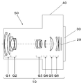
- FIG. 16 is a schematic configuration diagram of a digital camera 50 to which the zoom lens system according to the first embodiment is applied. It is also possible to apply the zoom lens according to the second to fifth embodiments.
- the digital camera 50 includes a housing 40, a zoom lens system 10 including an imaging device 20, and a monitor 30.
- the imaging element 20 is disposed at the position of the image plane S of the zoom lens system 10.
- an actuator or a lens is moved so that all the lens units from the first lens unit G1 to the sixth lens unit G6 move along the optical axis during zooming.
- the frame is configured.
- Z distance from a point on the aspheric surface at a height of h from the optical axis to the tangent plane of the aspheric vertex
- h height from the optical axis
- r vertex radius of curvature
- ⁇ conic constant
- An n-th order aspheric coefficient.
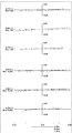
- FIGS. 2, 5, 8, 11, and 14 are longitudinal aberration diagrams of an imaging optical system at infinity focusing according to the first to fifth embodiments, respectively.
- each longitudinal aberration diagram shows the wide-angle end, (b) shows the intermediate position, and (c) shows the aberration at the telephoto end.
- Each longitudinal aberration figure shows spherical aberration (SA (mm)), astigmatism (AST (mm)), and distortion (DIS (%)) sequentially from the left side.
- the vertical axis represents the f-number (indicated by F in the figure)
- the solid line represents d-line
- the short broken line represents f-line
- the long broken line represents c-line (C- line) characteristics.
- the vertical axis represents the image height (indicated by H in the figure)
- the solid line represents the sagittal plane (indicated by s in the figure)
- the broken line represents the characteristics of the meridional plane (indicated by m in the figure). is there.
- the vertical axis represents the image height (indicated by H in the figure).
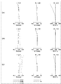
- FIGS. 3, 6, 9, 12 and 15 are lateral aberration diagrams of the imaging optical system at the telephoto end according to Embodiments 1 to 5, respectively.
- each lateral aberration diagram the upper three aberration diagrams show the basic state without image blur correction at the telephoto end, and the lower three aberration diagrams show the image blur correction lens unit moved a predetermined amount in the direction perpendicular to the optical axis.
- the upper row shows the lateral aberration at the image point of 70% of the maximum image height
- the middle row shows the lateral aberration at the axial image point
- the lower row shows the horizontal aberration at the image point of -70% of the maximum image height Correspond to each.
- the upper stage shows the lateral aberration at the image point of 70% of the maximum image height
- the middle stage shows the lateral aberration at the axial image point
- the lower stage shows the image point at -70% of the maximum image height
- the horizontal axis represents the distance from the chief ray on the pupil plane
- the solid line represents d-line
- the short broken line represents F-line
- the long broken line represents C-line C-line) characteristics.
- the meridional plane is a plane including the optical axis of the third lens group G3 (Embodiments 1 to 5) of the first lens group G1.
- the amount of movement of the image blur compensating lens unit in the direction perpendicular to the optical axis in the image blur compensation state at the telephoto end is as follows.
- the image eccentricity amount when the imaging optical system is inclined by 0.4 degrees at the telephoto end when the imaging distance is ⁇ is the image when the image blur correcting lens unit moves in parallel in the direction perpendicular to the optical axis by the above values. Equal to the amount of eccentricity.
- the symmetry of the lateral aberration at the on-axis image point is good.
- the degree of curvature is small and the inclination of the aberration curve is almost equal. It can be seen that the aberration is small. This means that sufficient imaging performance is obtained even in the image blur correction state.
- the image blur correction angle of the imaging optical system is the same, as the focal length of the entire imaging optical system becomes shorter, the amount of translation required for the image blurring correction decreases. Therefore, at any zoom position, it is possible to perform sufficient image blur correction for the image blur correction angle of about 0.4 ° without degrading the imaging characteristics.
- the imaging optical system of the numerical value example 1 corresponds to the first embodiment shown in FIG.
- Table 1 shows surface data of the image pickup optical system of Numerical Example 1.
- Table 2 shows aspheric surface data.
- Table 3A to Table 3D show various data in the infinity focusing state.
- the imaging optical system of the numerical value example 2 corresponds to the second embodiment shown in FIG.
- Table 4 shows the surface data of the imaging optical system of Numerical Example 2;
- Table 5 shows the aspheric surface data;
- Table 6A to Table 6D show various data in the infinity focusing state.
- the imaging optical system of the numerical value example 3 corresponds to the third embodiment shown in FIG.
- Table 7 shows the surface data of the imaging optical system of Numerical Example 3
- Table 8 shows the aspheric surface data
- Table 9A to Table 9D show various data in the infinity focusing state.
- the imaging optical system of the numerical value example 4 corresponds to the fourth embodiment shown in FIG.
- Table 10 shows the surface data of the imaging optical system of Numerical Example 4 and Table 11 shows the aspheric surface data, and Table 12A to Table 12D show various data in the infinity focusing state.
- the imaging optical system of the numerical value example 5 corresponds to the fifth embodiment shown in FIG.
- Table 13 shows the surface data of the image pickup optical system of Numerical Embodiment 5
- Table 14 shows the aspheric surface data
- Table 15A to Table 15D show various data in the infinity focusing state.
- the imaging optical system includes a digital still camera, an interchangeable lens digital camera, a digital video camera, a camera of a mobile phone device, a camera of a PDA (Personal Digital Assistance), a surveillance camera in a surveillance system, a web camera, an in-vehicle camera, etc.
- the present invention is suitable for photographing optical systems that require high image quality such as digital still camera systems and digital video camera systems.
Landscapes
- Physics & Mathematics (AREA)
- General Physics & Mathematics (AREA)
- Optics & Photonics (AREA)
- Nonlinear Science (AREA)
- Lenses (AREA)
- Adjustment Of Camera Lenses (AREA)
Priority Applications (4)
| Application Number | Priority Date | Filing Date | Title |
|---|---|---|---|
| CN201880004894.8A CN110050217B (zh) | 2017-10-27 | 2018-10-16 | 变焦透镜系统以及摄像装置 |
| JP2019519433A JP6664068B2 (ja) | 2017-10-27 | 2018-10-16 | ズームレンズ系、及び撮像装置 |
| EP18871395.2A EP3702823A4 (en) | 2017-10-27 | 2018-10-16 | ZOOM LENS SYSTEM AND IMAGING DEVICE |
| US16/440,071 US11150442B2 (en) | 2017-10-27 | 2019-06-13 | Zoom lens system and imaging device |
Applications Claiming Priority (2)
| Application Number | Priority Date | Filing Date | Title |
|---|---|---|---|
| JP2017208352 | 2017-10-27 | ||
| JP2017-208352 | 2017-10-27 |
Related Child Applications (1)
| Application Number | Title | Priority Date | Filing Date |
|---|---|---|---|
| US16/440,071 Continuation US11150442B2 (en) | 2017-10-27 | 2019-06-13 | Zoom lens system and imaging device |
Publications (1)
| Publication Number | Publication Date |
|---|---|
| WO2019082723A1 true WO2019082723A1 (ja) | 2019-05-02 |
Family
ID=66247319
Family Applications (1)
| Application Number | Title | Priority Date | Filing Date |
|---|---|---|---|
| PCT/JP2018/038404 WO2019082723A1 (ja) | 2017-10-27 | 2018-10-16 | ズームレンズ系、及び撮像装置 |
Country Status (5)
| Country | Link |
|---|---|
| US (1) | US11150442B2 (zh) |
| EP (1) | EP3702823A4 (zh) |
| JP (1) | JP6664068B2 (zh) |
| CN (1) | CN110050217B (zh) |
| WO (1) | WO2019082723A1 (zh) |
Families Citing this family (1)
| Publication number | Priority date | Publication date | Assignee | Title |
|---|---|---|---|---|
| CN114647070B (zh) * | 2022-03-25 | 2023-10-10 | 杭州海康威视数字技术股份有限公司 | 光学系统 |
Citations (6)
| Publication number | Priority date | Publication date | Assignee | Title |
|---|---|---|---|---|
| JP2012155087A (ja) | 2011-01-25 | 2012-08-16 | Nikon Corp | 変倍光学系、光学装置、変倍光学系の製造方法 |
| JP2015135392A (ja) * | 2014-01-17 | 2015-07-27 | セイコーエプソン株式会社 | 投射光学系及び投射型画像表示装置 |
| JP2016065912A (ja) * | 2014-09-24 | 2016-04-28 | 株式会社ニコン | ズームレンズ、光学機器及びズームレンズの製造方法 |
| JP2016161887A (ja) * | 2015-03-05 | 2016-09-05 | キヤノン株式会社 | ズームレンズ及びそれを有する撮像装置 |
| JP2016173438A (ja) | 2015-03-17 | 2016-09-29 | キヤノン株式会社 | ズームレンズ |
| JP2017142349A (ja) * | 2016-02-10 | 2017-08-17 | リコーイメージング株式会社 | ズームレンズ系 |
Family Cites Families (25)
| Publication number | Priority date | Publication date | Assignee | Title |
|---|---|---|---|---|
| JP3054185B2 (ja) | 1990-10-23 | 2000-06-19 | オリンパス光学工業株式会社 | ズームレンズ |
| US5691851A (en) | 1993-07-14 | 1997-11-25 | Canon Kabushiki Kaisha | Zoom lens |
| JP3155884B2 (ja) | 1993-07-14 | 2001-04-16 | キヤノン株式会社 | ズームレンズ |
| US7796344B2 (en) * | 2008-04-02 | 2010-09-14 | Panasonic Corporation | Zoom lens system, interchangeable lens apparatus and camera system |
| US8068281B2 (en) | 2008-04-02 | 2011-11-29 | Panasonic Corporation | Zoom lens system, interchangeable lens apparatus and camera system |
| JP4560745B2 (ja) | 2008-08-06 | 2010-10-13 | ソニー株式会社 | 可変焦点距離レンズ系 |
| JP5440760B2 (ja) | 2009-05-19 | 2014-03-12 | 株式会社ニコン | 変倍光学系、この変倍光学系を有する光学機器 |
| CN105388602B (zh) | 2011-01-25 | 2018-06-08 | 株式会社尼康 | 变焦镜头系统和光学设备 |
| JPWO2014006653A1 (ja) | 2012-07-04 | 2016-06-02 | パナソニックIpマネジメント株式会社 | ズームレンズ系、撮像装置及びカメラ |
| US8976271B2 (en) | 2012-07-19 | 2015-03-10 | Canon Kabushiki Kaisha | Optical system and image pickup apparatus |
| JP5649622B2 (ja) | 2012-07-19 | 2015-01-07 | キヤノン株式会社 | 光学系および撮像装置 |
| JP6230267B2 (ja) | 2013-05-23 | 2017-11-15 | キヤノン株式会社 | ズームレンズ及びそれを有する撮像装置 |
| JP6064217B2 (ja) | 2013-09-27 | 2017-01-25 | パナソニックIpマネジメント株式会社 | ズームレンズ系、交換レンズ装置及びカメラシステム |
| JP6253363B2 (ja) * | 2013-11-21 | 2017-12-27 | キヤノン株式会社 | ズームレンズ及びそれを有する撮像装置 |
| JP6350096B2 (ja) * | 2014-08-08 | 2018-07-04 | 株式会社シグマ | ズームレンズ系及びそれを有する撮像装置 |
| WO2016047129A1 (ja) * | 2014-09-24 | 2016-03-31 | 株式会社ニコン | ズームレンズ、光学機器及びズームレンズの製造方法 |
| JP6577191B2 (ja) | 2015-01-08 | 2019-09-18 | 株式会社タムロン | ズームレンズ及び撮像装置 |
| JP2016156942A (ja) * | 2015-02-24 | 2016-09-01 | 株式会社ニコン | ズームレンズ、光学機器及びズームレンズの製造方法 |
| JP2016166972A (ja) | 2015-03-10 | 2016-09-15 | キヤノン株式会社 | ズームレンズ及びそれを有する撮像装置 |
| JP6598599B2 (ja) * | 2015-09-02 | 2019-10-30 | キヤノン株式会社 | ズームレンズ及びそれを有する撮像装置 |
| JP6880544B2 (ja) * | 2015-09-30 | 2021-06-02 | 株式会社ニコン | ズームレンズおよび光学機器 |
| JP2017068155A (ja) * | 2015-10-01 | 2017-04-06 | キヤノン株式会社 | ズームレンズ及びそれを有する撮像装置 |
| CN107272172A (zh) * | 2016-04-06 | 2017-10-20 | 奥林巴斯株式会社 | 变倍光学系统和具有该变倍光学系统的摄像装置 |
| JP6789719B2 (ja) * | 2016-08-09 | 2020-11-25 | キヤノン株式会社 | ズームレンズ及びそれを有する撮像装置 |
| JP6779710B2 (ja) | 2016-08-30 | 2020-11-04 | キヤノン株式会社 | ズームレンズ及びそれを有する撮像装置 |
-
2018
- 2018-10-16 JP JP2019519433A patent/JP6664068B2/ja active Active
- 2018-10-16 EP EP18871395.2A patent/EP3702823A4/en active Pending
- 2018-10-16 CN CN201880004894.8A patent/CN110050217B/zh active Active
- 2018-10-16 WO PCT/JP2018/038404 patent/WO2019082723A1/ja unknown
-
2019
- 2019-06-13 US US16/440,071 patent/US11150442B2/en active Active
Patent Citations (6)
| Publication number | Priority date | Publication date | Assignee | Title |
|---|---|---|---|---|
| JP2012155087A (ja) | 2011-01-25 | 2012-08-16 | Nikon Corp | 変倍光学系、光学装置、変倍光学系の製造方法 |
| JP2015135392A (ja) * | 2014-01-17 | 2015-07-27 | セイコーエプソン株式会社 | 投射光学系及び投射型画像表示装置 |
| JP2016065912A (ja) * | 2014-09-24 | 2016-04-28 | 株式会社ニコン | ズームレンズ、光学機器及びズームレンズの製造方法 |
| JP2016161887A (ja) * | 2015-03-05 | 2016-09-05 | キヤノン株式会社 | ズームレンズ及びそれを有する撮像装置 |
| JP2016173438A (ja) | 2015-03-17 | 2016-09-29 | キヤノン株式会社 | ズームレンズ |
| JP2017142349A (ja) * | 2016-02-10 | 2017-08-17 | リコーイメージング株式会社 | ズームレンズ系 |
Non-Patent Citations (1)
| Title |
|---|
| See also references of EP3702823A4 |
Also Published As
| Publication number | Publication date |
|---|---|
| JPWO2019082723A1 (ja) | 2019-11-14 |
| US11150442B2 (en) | 2021-10-19 |
| CN110050217B (zh) | 2021-11-02 |
| CN110050217A (zh) | 2019-07-23 |
| EP3702823A4 (en) | 2020-12-23 |
| EP3702823A1 (en) | 2020-09-02 |
| JP6664068B2 (ja) | 2020-03-13 |
| US20190293906A1 (en) | 2019-09-26 |
Similar Documents
| Publication | Publication Date | Title |
|---|---|---|
| JP4869288B2 (ja) | ズームレンズ及びそれを有する撮像装置 | |
| JP5658811B2 (ja) | ズームレンズ系、交換レンズ装置及びカメラシステム | |
| CN108535850B (zh) | 变焦透镜和包括变焦透镜的图像拾取装置 | |
| JP5241281B2 (ja) | ズームレンズ及びそれを有する撮像装置 | |
| US8107171B2 (en) | Zoom lens system and image pickup apparatus including the same | |
| JP2009282398A5 (zh) | ||
| JP5436518B2 (ja) | ズームレンズ及びそれを有する撮像装置 | |
| JP5858829B2 (ja) | ズームレンズおよびこれを用いた撮像装置 | |
| JP5959938B2 (ja) | ズームレンズ及びそれを有する撮像装置 | |
| JP5919519B2 (ja) | ズームレンズ系、撮像装置及びカメラ | |
| JP2013195749A (ja) | ズームレンズ及びそれを有する撮像装置 | |
| JP2009223008A5 (zh) | ||
| WO2014129187A1 (ja) | ズームレンズ系、交換レンズ装置及びカメラシステム | |
| JP2016173556A (ja) | ズームレンズ系およびカメラシステム | |
| JP5921220B2 (ja) | ズームレンズ及びそれを有する撮像装置 | |
| JP2020134892A (ja) | ズームレンズ及びそれを有する撮像装置 | |
| JP2012198505A (ja) | ズームレンズ系、撮像装置及びカメラ | |
| WO2014006653A1 (ja) | ズームレンズ系、撮像装置及びカメラ | |
| JP5919518B2 (ja) | ズームレンズ系、撮像装置及びカメラ | |
| JP2012198506A (ja) | ズームレンズ系、撮像装置及びカメラ | |
| JP6579828B2 (ja) | ズームレンズ及びそれを有する撮像装置 | |
| JP5208256B2 (ja) | ズームレンズ及びそれを有する撮像装置 | |
| JP2017037163A (ja) | ズームレンズ及びそれを有する撮像装置 | |
| JP6635256B2 (ja) | ズームレンズ及びそれを有する撮像装置 | |
| JP7178554B2 (ja) | ズームレンズ系とそれを備える撮像装置およびカメラシステム |
Legal Events
| Date | Code | Title | Description |
|---|---|---|---|
| ENP | Entry into the national phase |
Ref document number: 2019519433 Country of ref document: JP Kind code of ref document: A |
|
| 121 | Ep: the epo has been informed by wipo that ep was designated in this application |
Ref document number: 18871395 Country of ref document: EP Kind code of ref document: A1 |
|
| NENP | Non-entry into the national phase |
Ref country code: DE |
|
| ENP | Entry into the national phase |
Ref document number: 2018871395 Country of ref document: EP Effective date: 20200527 |