WO2019073759A1 - 車両用空調装置 - Google Patents
車両用空調装置 Download PDFInfo
- Publication number
- WO2019073759A1 WO2019073759A1 PCT/JP2018/034457 JP2018034457W WO2019073759A1 WO 2019073759 A1 WO2019073759 A1 WO 2019073759A1 JP 2018034457 W JP2018034457 W JP 2018034457W WO 2019073759 A1 WO2019073759 A1 WO 2019073759A1
- Authority
- WO
- WIPO (PCT)
- Prior art keywords
- air
- dust sensor
- dust
- control
- vehicle
- Prior art date
- Legal status (The legal status is an assumption and is not a legal conclusion. Google has not performed a legal analysis and makes no representation as to the accuracy of the status listed.)
- Ceased
Links
Images


Classifications
-
- B—PERFORMING OPERATIONS; TRANSPORTING
- B60—VEHICLES IN GENERAL
- B60H—ARRANGEMENTS OF HEATING, COOLING, VENTILATING OR OTHER AIR-TREATING DEVICES SPECIALLY ADAPTED FOR PASSENGER OR GOODS SPACES OF VEHICLES
- B60H1/00—Heating, cooling or ventilating [HVAC] devices
- B60H1/00642—Control systems or circuits; Control members or indication devices for heating, cooling or ventilating devices
- B60H1/00735—Control systems or circuits characterised by their input, i.e. by the detection, measurement or calculation of particular conditions, e.g. signal treatment, dynamic models
- B60H1/008—Control systems or circuits characterised by their input, i.e. by the detection, measurement or calculation of particular conditions, e.g. signal treatment, dynamic models the input being air quality
-
- B—PERFORMING OPERATIONS; TRANSPORTING
- B60—VEHICLES IN GENERAL
- B60H—ARRANGEMENTS OF HEATING, COOLING, VENTILATING OR OTHER AIR-TREATING DEVICES SPECIALLY ADAPTED FOR PASSENGER OR GOODS SPACES OF VEHICLES
- B60H1/00—Heating, cooling or ventilating [HVAC] devices
-
- B—PERFORMING OPERATIONS; TRANSPORTING
- B60—VEHICLES IN GENERAL
- B60H—ARRANGEMENTS OF HEATING, COOLING, VENTILATING OR OTHER AIR-TREATING DEVICES SPECIALLY ADAPTED FOR PASSENGER OR GOODS SPACES OF VEHICLES
- B60H1/00—Heating, cooling or ventilating [HVAC] devices
- B60H1/00642—Control systems or circuits; Control members or indication devices for heating, cooling or ventilating devices
- B60H1/0073—Control systems or circuits characterised by particular algorithms or computational models, e.g. fuzzy logic or dynamic models
-
- B—PERFORMING OPERATIONS; TRANSPORTING
- B60—VEHICLES IN GENERAL
- B60H—ARRANGEMENTS OF HEATING, COOLING, VENTILATING OR OTHER AIR-TREATING DEVICES SPECIALLY ADAPTED FOR PASSENGER OR GOODS SPACES OF VEHICLES
- B60H1/00—Heating, cooling or ventilating [HVAC] devices
- B60H1/24—Devices purely for ventilating or where the heating or cooling is irrelevant
-
- B—PERFORMING OPERATIONS; TRANSPORTING
- B60—VEHICLES IN GENERAL
- B60H—ARRANGEMENTS OF HEATING, COOLING, VENTILATING OR OTHER AIR-TREATING DEVICES SPECIALLY ADAPTED FOR PASSENGER OR GOODS SPACES OF VEHICLES
- B60H3/00—Other air-treating devices
- B60H3/06—Filtering
-
- F—MECHANICAL ENGINEERING; LIGHTING; HEATING; WEAPONS; BLASTING
- F24—HEATING; RANGES; VENTILATING
- F24F—AIR-CONDITIONING; AIR-HUMIDIFICATION; VENTILATION; USE OF AIR CURRENTS FOR SCREENING
- F24F11/00—Control or safety arrangements
- F24F11/30—Control or safety arrangements for purposes related to the operation of the system, e.g. for safety or monitoring
- F24F11/32—Responding to malfunctions or emergencies
- F24F11/38—Failure diagnosis
-
- F—MECHANICAL ENGINEERING; LIGHTING; HEATING; WEAPONS; BLASTING
- F24—HEATING; RANGES; VENTILATING
- F24F—AIR-CONDITIONING; AIR-HUMIDIFICATION; VENTILATION; USE OF AIR CURRENTS FOR SCREENING
- F24F11/00—Control or safety arrangements
- F24F11/62—Control or safety arrangements characterised by the type of control or by internal processing, e.g. using fuzzy logic, adaptive control or estimation of values
- F24F11/63—Electronic processing
- F24F11/65—Electronic processing for selecting an operating mode
Definitions
- the present disclosure relates to a vehicle air conditioner provided with a dust sensor.
- Patent Document 1 Conventionally, there is a vehicle air conditioner described in Patent Document 1 below.
- the vehicle air conditioner described in Patent Document 1 adjusts the temperature of the air taken in from the vehicle interior or the vehicle exterior, and blows the conditioned air, which is the temperature-adjusted air, into the vehicle interior.
- the temperature of air is adjusted by the heater core and the evaporator provided in the air conditioning unit.
- the inventors of the present invention have been examining providing a vehicle air conditioner with a function of measuring the concentration of dust such as particulate matter (for example, PM 2.5) floating in the air.
- a dust sensor for optically measuring the concentration of dust is provided in a vehicle air conditioner, and a portion of the air sucked from the vehicle compartment into the air conditioning unit is made to flow to the dust sensor, It is possible to measure the concentration of dust in the air.
- problems such as erroneous detection of the dust concentration or failure to detect the dust itself may occur.
- An object of the present disclosure is to provide a vehicle air conditioner capable of determining the presence or absence of a dust sensor failure.
- a vehicle air conditioner includes an air conditioning unit, a dust sensor, and a failure determination unit.
- the air conditioning unit air-conditions the passenger compartment.
- the dust sensor detects the concentration of dust contained in the air flowing through the air conditioning unit, and outputs a detection value corresponding to the detected dust concentration.
- the failure determination unit executes predetermined control for changing the detection value of the dust sensor, and determines the presence or absence of the failure of the dust sensor based on the detection value of the dust sensor after execution of the predetermined control.
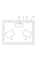
- FIG. 1 is a block diagram showing a schematic configuration of the vehicle air conditioner of the first embodiment.
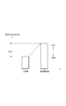
- FIG. 2 is a cross-sectional view showing a schematic configuration of the dust sensor of the first embodiment.
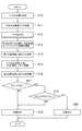
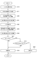
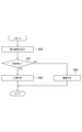
- FIG. 3 is a flowchart showing the procedure of processing executed by the ECU of the first embodiment.
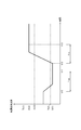
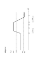
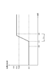
- FIG. 4 is a timing chart showing an operation example of the dust sensor of the first embodiment.
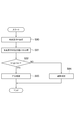
- FIG. 5 is a flowchart showing the procedure of processing executed by the ECU of the modification of the first embodiment.
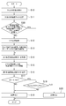
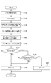
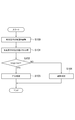
- FIG. 6 is a flowchart showing the procedure of processing executed by the ECU of the second embodiment.
- FIG. 7 is a timing chart showing an operation example of the dust sensor of the second embodiment.
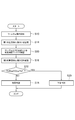
- FIG. 8 is a flowchart showing the procedure of processing executed by the ECU of the third embodiment.
- FIG. 9 is a timing chart showing an operation example of the dust sensor of the third embodiment.
- FIG. 10 is a flowchart showing the procedure of processing executed by the ECU of the first modified example of the third embodiment.
- FIG. 11 is a flowchart showing the procedure of processing executed by the ECU of the second modified example of the third embodiment.
- FIG. 12 is a timing chart showing an operation example of the dust sensor of the second modified example of the third embodiment.
- FIG. 13 is a flowchart showing the procedure of processing executed by the ECU of the fourth embodiment.
- FIG. 14 is a flowchart showing the procedure of processing executed by the ECU of the fifth embodiment.
- FIG. 15 is a timing chart showing an operation example of the dust sensor of the fifth embodiment.
- FIG. 16 is a flowchart showing the procedure of processing executed by the ECU of the sixth embodiment.
- FIG. 17 is a timing chart showing an operation example of the dust sensor of the sixth embodiment.
- the vehicle air conditioner 10 of the present embodiment shown in FIG. 1 is mounted on a vehicle and is an apparatus for performing air conditioning in a vehicle interior.
- the vehicle air conditioner 10 includes an air conditioning unit 20, a dust sensor 30, an operation device 40, a display device 50, and an electronic control unit (ECU) 60.
- ECU electronice control unit
- the air conditioning unit 20 is a main part of the vehicle air conditioner 10, and performs air conditioning of the air taken in from the vehicle interior or the vehicle exterior, and supplies the conditioned air, which is the air conditioned air, to the vehicle interior.
- the air conditioning unit 20 includes a blower storage unit 21, a blower device 22, a connection unit 23, and an air conditioning unit 24.
- the air in the passenger compartment is also referred to as “inner air”
- the air outside the passenger compartment is also referred to as "outside air”.
- the blower storage portion 21 is a portion for taking in air.
- a blower device 22 is accommodated inside the blower accommodating portion 21.
- An inside air intake port 210 and an outside air intake port 211 are formed in the blower housing portion 21.
- the inside air suction port 210 is an opening formed as an inlet of air introduced from the vehicle compartment.
- the space in the passenger compartment and the inside air suction port 210 are connected by a duct (not shown).
- the fresh air suction port 211 is an opening formed as an inlet for air introduced from the outside of the vehicle.
- the space outside the passenger compartment and the outside air intake port 211 are also connected by a duct (not shown).
- An inside / outside air switching door 212 is provided between the inside air inlet 210 and the outside air inlet 211 in the blower housing 21.
- the inside / outside air switching door 212 adjusts the opening degree of each of the inside air inlet 210 and the outside air inlet 211. Specifically, when the inside / outside air switching door 212 is located at the outside air introducing position shown by a solid line in the drawing, the inside air intake port 210 is closed and the outside air intake port 211 is opened. In this case, the air conditioning unit 20 enters an outside air introduction mode in which the outside air is sucked from the outside air inlet 211. In the outside air introduction mode, the atmosphere outside the vehicle is blown out into the vehicle interior.
- the air conditioning unit 20 is in the inside air circulation mode in which the inside air is taken in from the inside air inlet 210.
- the air in the passenger compartment circulates through the air conditioning unit 20 and is blown out into the passenger compartment.
- the opening degree of each of the inside air inlet 210 and the outside air inlet 211 by the inside / outside air switching door 212 the flow rate of air sucked into the air conditioning unit 20 from the inside air inlet 210 and the outside air inlet 211
- the ratio to the flow rate of air drawn into the air conditioning unit 20 can also be adjusted.
- a filter 25 is disposed on the air flow upstream side of the blower device 22 in the blower housing portion 21.
- the filter 25 removes dust, dirt and the like contained in the air flowing in from the inside air inlet 210 and the outside air inlet 211. That is, when the air introduced from the inside air intake port 210 or the outside air intake port 211 passes through the filter 25, clean air from which dust, dust and the like are removed is blown out into the vehicle interior.
- the filter 25 is replaceable.
- the blower device 22 is a device that generates an air flow blown into the vehicle compartment.
- air is drawn into the blower housing 21 from the inside air inlet 210 and the outside air inlet 211.
- the air is blown out into the vehicle compartment through the connection 23 and the air conditioner 24.
- the power supplied to the blower device 22 it is possible to adjust the flow rate of air drawn into the blower housing 21, in other words, the air volume of the conditioned air blown out into the vehicle compartment.
- connection portion 23 is a portion provided as a flow path connecting the blower housing portion 21 and the air conditioning portion 24.
- the connection portion 23 is integrally formed with the blower housing portion 21.
- the air conditioning unit 24 is a part that performs temperature control of air. Inside the air conditioning unit 24, an evaporator for dehumidifying and cooling the air, a heater core for heating the air, an air mix door for adjusting the flow rate of air flowing through the evaporator and the heater core, and the like are arranged.
- a defroster blowout unit 240, a face blowout unit 241, and a foot blowout unit 242 are provided on the air flow direction downstream side of the air conditioning unit 24, respectively.
- the defroster blowout portion 240 is a portion that blows the conditioned air toward the windshield of the vehicle.
- the face blowing portion 241 is a portion that blows the conditioned air toward the face of the vehicle occupant.
- the foot blowing portion 242 is a portion that blows the conditioned air toward the foot of the vehicle occupant.
- a door (not shown) is provided in each of the defroster blowout portion 240, the face blowout portion 241, and the foot blowout portion 242, and the flow rate of air blown out from each blowout portion is adjusted according to the opening degree of the door.
- An air introduction chamber 213 is formed in a portion near the end of the filter 25 in the blower housing 21.
- the air introduction chamber 213 is formed as a space through which the air flowing into the air conditioning unit 20 from the outside of the air conditioning unit 20, more specifically, the air introduced into the blower housing 21 from the outside of the air conditioning unit 20 flows. .
- An opening 214 serving as an air inlet of the air introduction chamber 213 is located above the filter 25 and the dust sensor 30.
- the opening 214 communicates the space around the air conditioning unit 20 with the air introduction chamber 213.
- An opening 215 which is an outlet of air in the air introduction chamber 213 is formed at a position slightly below the filter 25.
- the opening 215 communicates the air introduction chamber 213 with the space on the lower side of the filter 25 in the blower housing 21.
- the positions of the opening 214 and the opening 215 as described above are merely examples.
- the opening 214 and the opening 215 may be formed at positions different from the above.
- the air in the air introduction chamber 213 is discharged to the blower device 22 through the opening 215 by the suction force of the blower device 22.
- external air flows into the air introduction chamber 213 through the opening 214.
- air flows from the opening 214 toward the opening 215.
- the blower storage portion 21 is disposed inside the instrument panel of the vehicle.
- the space inside the instrument panel that is, the space outside the air introduction chamber 213 is connected to the vehicle interior. Therefore, the air flowing into the air introduction chamber 213 from the opening 214 is the air in the vehicle compartment.
- the part in which the air introduction chamber 213 in the air conditioning unit 20 is formed is a part to which the dust sensor 30 is attached.
- the dust sensor 30 is attached to the blower housing 21 from the outside so as to divide the side portion of the air introduction chamber 213.
- the dust sensor 30 measures the concentration of dust containing particles such as PM 2.5 in the intake air.
- the dust sensor 30 has a case 31, a light emitting element 32 and a light receiving element 33.
- An opening 310 is formed in the outer wall of the case 31 facing the air introduction chamber 213.
- a space in the case 31 is an air passage 311 through which the air introduced from the opening 310 passes.
- the light emitting element 32 and the light receiving element 33 are disposed in the air passage 311 in the case 31.
- the light emitting element 32 emits light into the air passage 311. Some of the light emitted from the light emitting element 32 is scattered by dust in the air introduced into the air passage 311.
- the light receiving element 33 receives the scattered light scattered by the dust and outputs an electrical signal according to the amount of light received. That is, the electrical signal output from the light receiving element 33 changes with the concentration of dust contained in the air flowing in the air passage 311.
- the dust sensor 30 outputs an electrical signal output from the light receiving element 33 as a dust concentration detection value.
- the electric signal output from the light receiving element 33 is also referred to as an "output value".
- the operating device 40 illustrated in FIG. 1 is a portion operated by the driver when adjusting the air volume, temperature, and the like of the conditioned air.
- the operating device 40 is disposed, for example, on an instrument panel of a vehicle. In the operation device 40, for example, any one of the outside air introduction mode and the inside air circulation mode can be selected. Further, in the operation device 40, the air volume of the air conditioning air, the temperature of the air conditioning air, the outlet of the air conditioning air, and the like can be set.
- the operating device 40 outputs the operation information to the ECU 60.
- the display device 50 is a portion that displays various information of the vehicle air conditioner 10.
- a touch panel or the like used for a car navigation device of a vehicle can be diverted.
- the display device 50 may be a device provided exclusively for the vehicle air conditioner 10.
- the ECU 60 is mainly configured of a microcomputer having a CPU 61, a memory 62, and the like.
- the ECU 60 acquires operation information from the operation device 40, and drives the air conditioning unit 20 based on the acquired operation information.
- the air conditioning unit 20 generates the conditioned air according to the operation information of the operating device 40, and the conditioned air is blown out into the vehicle interior to perform the air conditioning of the vehicle interior.
- the detection signal of the dust sensor 30 is taken into the ECU 60.
- the ECU 60 acquires dust concentration information based on the detection signal of the dust sensor 30, and displays the acquired dust concentration information on the display device 50.
- the ECU 60 can also open and close windows respectively provided on a plurality of doors of the vehicle. Specifically, the ECU 60 can automatically open and close the windows of the plurality of doors of the vehicle by transmitting the command signal to the window opening and closing device 70 of the vehicle, regardless of the operation of the vehicle occupant. .
- the ECU 60 can communicate with a diagnostic device 80 connected from the outside of the vehicle.
- the diagnostic device 80 can be connected to an external input / output terminal provided in a vehicle or can be detached from the external input / output terminal.
- the diagnosis device 80 is operated by a dealer or the like, and detects the abnormality of the vehicle by software or repairs the detected abnormality by software by connecting and operating the external input / output terminal of the vehicle. Can be Further, the diagnosis device 80 has a screen on which various information can be displayed.
- the diagnosis device 80 is communicably connected to the server device 82 via the network line 81.
- the diagnosis device 80 can acquire various types of information from the server device 82 through the network line 81, and can transmit the acquired information to the ECU 60.
- the information that can be acquired from the server device 82 includes information on the current dust concentration of the atmosphere, and the like.
- the ECU 60 executes a failure determination process of determining whether the dust sensor 30 has a failure. That is, in the present embodiment, the ECU 60 functions as a failure determination unit. Next, with reference to FIG. 3, a specific procedure of the failure determination process executed by the ECU 60 will be described. The ECU 60 starts the process shown in FIG. 3 when the diagnostic device 80 is connected to the vehicle.
- the ECU 60 performs notification to prompt replacement of the filter 25 as the process of step S10. Specifically, the ECU 60 requests the diagnostic device 80 to issue a notification prompting replacement of the filter 25. As a result, an image for prompting replacement of the filter 25 is displayed on the screen of the diagnostic device 80, so that a worker who operates the diagnostic device 80 can perform replacement work of the filter. As described above, in the present embodiment, the ECU 60 also functions as a notification unit that performs notification notifying replacement of the filter 25.
- step S10 it may be determined whether notification is to be performed according to the use period of the filter 25 or the like. Further, after detecting that the replacement work of the filter 25 is completed through the operation of the diagnosis device 80, the ECU 60 executes the processing of step S11 and subsequent steps.
- the ECU 60 acquires information on the dust concentration Th1 of the air from the diagnosis device 80 and stores the information in the memory 62 as the process of step S11. Thereafter, the ECU 60 closes the windows of all the doors of the vehicle as the process of step S12, and then sets the air conditioning unit 20 in the inside air circulation mode for a predetermined time T10 as the process of step S13. And the blower device 22 is driven.
- the processes shown in steps S12 and S13 correspond to the interior purification control.
- the ECU 60 acquires the first dust concentration detection value DC1 based on the detection signal output from the dust sensor 30, and stores the first dust concentration detection value DC1 in the memory 62 as the process of step S14. That is, the first dust concentration detection value DC1 corresponds to the dust concentration detected by the dust sensor 30 when the air in the vehicle compartment is clean.
- the ECU 60 opens the window of at least one of the plurality of doors of the vehicle as a process of step S15 following the process of step S14, and then waits for a predetermined time T11.
- the air outside the passenger compartment is introduced into the passenger compartment, so the dust concentration in the passenger compartment, in other words, the dust concentration detected by the dust sensor 30, becomes a value corresponding to the dust concentration in the air.
- the process of step S15 corresponds to air introduction control.
- the ECU 60 acquires the second dust concentration detection value DC2 based on the detection signal output from the dust sensor 30, and stores the second dust concentration detection value DC2 in the memory 62 as the process of step S16. That is, the second dust concentration detection value DC2 is a dust concentration detected by the dust sensor 30 when the dust concentration in the vehicle compartment corresponds to the dust concentration of the air.
- the ECU 60 determines whether the first dust concentration detection value DC1 is equal to or less than the threshold value Th2 as the process of step S17 following the process of step S16.
- the threshold Th2 is set by experiment or the like so that it can be determined whether or not the first dust concentration detection value DC1 indicates the concentration of dust when the air in the vehicle compartment is clean. It is stored in advance in the memory 62.
- step S17 If the ECU 60 makes a negative determination in step S17, that is, if the first dust concentration detection value DC1 exceeds the threshold value Th2, the ECU 60 determines that the detection value DC1 is an abnormal value, and sets dust as the process of step S18. It is determined that the sensor 30 is in a failure state. In the process of step S18, for example, by displaying the failure of the dust sensor 30 on the screen of the diagnosis device 80, the operator of the diagnosis device 80 is made to recognize the failure of the dust sensor 30.
- the ECU 60 determines that the first dust concentration detection value DC1 indicates a normal value. In this case, the ECU 60 determines whether the second dust concentration detection value DC2 satisfies the relationship of “Th10 ⁇ DC2 ⁇ Th11” with respect to the threshold values Th10 and Th11 as the process of step S19.
- the threshold Th10 is set to a value smaller than the dust concentration Th1 of the air by a predetermined value.
- the threshold Th11 is set to a value larger than the dust concentration Th1 of the air by a predetermined value.
- the thresholds Th10 and Th11 are used to determine whether the second dust concentration detection value DC2 is a value near the dust concentration Th1 of the air.
- the ECU 60 makes a negative determination in the process of step S19, that is, if the second dust concentration detection value DC2 is less than the threshold Th10 or exceeds the threshold Th11, the second dust concentration detection value DC2 is an abnormal value. It is determined that In this case, the ECU 60 determines that the dust sensor 30 is in a failure state as the process of step S18.
- the ECU 60 makes an affirmative determination in the process of step S19, that is, if the second dust concentration detection value DC2 satisfies the relationship of “Th10 ⁇ DC2 ⁇ Th11”, the second dust concentration detection value DC2 is a normal value. Determine that there is. In this case, the ECU 60 determines that the dust sensor 30 is in the normal state as the process of step S20. In the process of step S20, for example, by displaying that the dust sensor 30 is normal on the screen of the diagnosis device 80, the operator who operates the diagnosis device 80 is made to recognize that the dust sensor 30 has no abnormality.
- the ECU 60 starts the process shown in FIG. 3 at time t10, for example, the ECU 60 first sets the windows of all the doors of the vehicle to the closed state and sets the inside air circulation mode In the state in which the air conditioning unit 20 is set, the in-room purification control for driving the blower device 22 is executed. Since the air in the passenger compartment is purified by the execution of the interior purification control, the detection value of the dust sensor 30 gradually decreases after time t10.
- the detection value of the dust sensor 30 is a value when air in the vehicle compartment is clean. Converge. Then, at time t11, the ECU 60 acquires the detection value of the dust sensor 30 as the first dust concentration detection value DC1.
- the ECU 60 determines that the first dust concentration detection value DC1 is a normal value. Therefore, at time t12 thereafter, the ECU 60 executes air introduction control for opening at least one of the plurality of doors of the vehicle. Since the air is introduced into the vehicle compartment by the execution of the air introduction control, the detected value of the dust sensor 30 gradually increases after time t12. Further, since the air introduction control is continued from time t12 to time t13 when the predetermined time T11 elapses, the detection value of the dust sensor 30 converges to a value corresponding to the dust concentration of the air. Then, at time t13, the ECU 60 acquires the detection value of the dust sensor 30 as the second dust concentration detection value DC2.
- the second dust concentration detection value DC2 is normal because the second dust concentration detection value DC2 satisfies the relationship “Th10 ⁇ DC2 ⁇ Th11” with respect to the threshold values Th10 and Th11. It is determined that it is a value. From the above, the ECU 60 determines that the dust sensor 30 is in the normal state.
- the ECU 60 determines the presence or absence of a failure of the dust sensor 30 based on the detection value of the dust sensor 30 after execution of the interior purification control and the detection value of the dust sensor after execution of the air introduction control. Specifically, the ECU 60 determines the presence or absence of a failure of the dust sensor 30 by executing the interior purification control, and then determines the presence or absence of a failure of the dust sensor 30 by executing air introduction control. Thereby, the presence or absence of a failure of the dust sensor 30 can be determined.
- the ECU 60 performs notification to urge replacement of the filter 25 provided in the air conditioning unit 20 before executing the interior purification control.
- the interior purification control is performed after the filter 25 is replaced, the interior of the vehicle is more easily cleaned. Therefore, it is possible to accurately detect the first dust concentration detection value DC1, which is the concentration of dust in a state where the interior of the vehicle has been cleaned, and as a result, it is possible to improve the determination accuracy of the failure of the dust sensor 30. it can.
- step S11 the ECU 60 of the present modification example closes the windows of all the doors of the vehicle in the period from the present to a predetermined time before as the process of step S30. Then, it is determined whether the air conditioning unit 20 is set to the internal air circulation mode and the blower device 22 continues to be driven.
- the ECU 60 makes an affirmative determination in the process of step S30, the ECU 60 executes the processes of step S14 and subsequent steps without executing the processes of steps S12 and S13.
- the ECU 60 makes a negative determination in the process of step S30, it executes the process of step S12 and subsequent steps.
- the in-room purification control of steps S12 and S13 by the ECU 60 It is determined whether the dust sensor 30 has a failure or not without being executed. Therefore, the failure determination result of the dust sensor 30 can be obtained earlier.
- the ECU 60 of the first embodiment executes the air introduction control after executing the interior purification control.
- the ECU 60 of the present embodiment differs from the ECU 60 of the first embodiment in that the interior purification control is performed after the atmosphere introduction control is performed.
- the ECU 60 of the present embodiment executes the process shown in FIG. 6 instead of the process shown in FIG.
- the ECU 60 opens the window of at least one door of the plurality of doors of the vehicle as the process of step S40, and then predetermined time T11 Just wait. Thereafter, the ECU 60 acquires the second dust concentration detection value DC2 based on the detection signal output from the dust sensor 30, and stores the second dust concentration detection value DC2 in the memory 62 as the process of step S41.
- the ECU 60 After closing the windows of all the doors of the vehicle as the process of step S42 following the process of step S41, the ECU 60 sets the inside air temperature of the air conditioning unit 20 for a predetermined time T10 as the process of step S43. The circulation mode is set and the blower device 22 is driven. Then, after completing the process of step S43, the ECU 60 acquires the first dust concentration detection value DC1 based on the detection signal output from the dust sensor 30 as the process of step S44, and stores this in the memory 62. . Thereafter, the ECU 60 executes the processing of step S17 and subsequent steps.
- the ECU 60 starts the process shown in FIG. 3 at time t20, for example, the ECU 60 first opens the window of at least one of the plurality of doors of the vehicle. Perform air introduction control. Since the air is introduced into the vehicle compartment by the execution of the air introduction control, the detected value of the dust sensor 30 gradually increases after time t20. Further, since the air introduction control is continued for a period from time t20 to time t21 when the predetermined time T11 elapses, the detection value of the dust sensor 30 converges to a value corresponding to the dust concentration of the air. Then, at time t22, the ECU 60 acquires the detection value of the dust sensor 30 as the second dust concentration detection value DC2.
- the second dust concentration detection value DC2 is normal because the second dust concentration detection value DC2 satisfies the relationship “Th10 ⁇ DC2 ⁇ Th11” with respect to the threshold values Th10 and Th11. It is determined that it is a value. Thereafter, at time t23, the ECU 60 controls the interior of the room to drive the blower device 22 with the windows of all the doors of the vehicle closed and the air conditioning unit 20 set to the internal air circulation mode. Run. Since the air in the passenger compartment is purified by the execution of the interior purification control, the detection value of the dust sensor 30 gradually decreases after time t23.
- the detection value of the dust sensor 30 is a value when the air in the vehicle compartment is clean. Converge. Then, at time t24, the ECU 60 acquires the detection value of the dust sensor 30 as the first dust concentration detection value DC1.
- the ECU 60 determines that the first dust concentration detection value DC1 is a normal value. From the above, the ECU 60 determines that the dust sensor 30 is in the normal state. According to the vehicle air conditioner 10 of the present embodiment described above, it is possible to obtain the same or similar operation and effect as the vehicle air conditioner 10 of the first embodiment.
- the vehicle air conditioner 10 of the present embodiment determines the presence or absence of a failure of the dust sensor 30 by using sample air instead of the air.
- the sample air indicates air in which the concentration of contained dust is known.
- the ECU 60 executes the process shown in FIG. 8 instead of the process shown in FIG.
- a sample air supply device for supplying sample air to the dust sensor 30 is installed near the opening 214 of the air introduction chamber 213 by an operator or the like before the process shown in FIG. 8 is performed.
- the ECU 60 supplies sample air to the dust sensor 30 as the process of step S50, and then waits for a predetermined time T11. Specifically, the ECU 60 supplies sample air to the dust sensor 30 by displaying an instruction for driving the sample air supply device on the screen of the diagnosis device 80 or directly operating the sample air supply device. .
- the process of step S50 corresponds to sample air supply control. Thereafter, the ECU 60 executes the processing of step S16 and subsequent steps.
- the threshold values Th10 and Th11 used in the process of step S19 are input by, for example, the diagnosis device 80 or the like so that it can be determined whether or not the second dust concentration detection value DC2 indicates the dust concentration of the sample air.
- the value to be used is used.
- the threshold Th10 is set to a value smaller than the input value of the diagnosis device 80 by a predetermined value.
- the threshold Th11 is set to a value larger than the input value of the diagnosis device 80 by a predetermined value.
- the ECU 60 executes sample air supply control at time t32. Since the sample air is supplied to the dust sensor 30 by execution of the sample air supply control, the detection value of the dust sensor 30 gradually increases after time t32. Further, since the sample air supply control is continued from time t32 to time t33 when the predetermined time T11 elapses, the detection value of the dust sensor 30 converges to a value corresponding to the dust concentration of the sample air. Then, at time t33, the ECU 60 acquires the detection value of the dust sensor 30 as the second dust concentration detection value DC2.
- the second dust concentration detection value DC2 is normal because the second dust concentration detection value DC2 satisfies the relationship “Th10 ⁇ DC2 ⁇ Th11” with respect to the threshold values Th10 and Th11. It is determined that it is a value. From the above, the ECU 60 determines that the dust sensor 30 is in the normal state.
- the actions and effects shown in the following (3) and (4) can be obtained.
- the ECU 60 After executing the interior purification control, the ECU 60 determines the presence or absence of a failure of the dust sensor 30 by executing the sample air supply control. As a result, only the sample air can be easily supplied to the dust sensor 30, and as a result, the determination accuracy of the failure of the dust sensor 30 can be improved.
- step S10 After executing the process of step S10, the ECU 60 of the present modification example closes the windows of all the doors of the vehicle in the period from the present to a predetermined time before as the process of step S60. Then, it is determined whether the air conditioning unit 20 is set to the internal air circulation mode and the blower device 22 continues to be driven.
- the ECU 60 makes an affirmative determination in the process of step S60, the ECU 60 executes the processes of step S14 and subsequent steps without executing the processes of steps S12 and S13.
- the ECU 60 makes a negative determination in the process of step S30, it executes the process of step S12 and subsequent steps.
- the in-room purification control of steps S12 and S13 by the ECU 60 It is determined whether the dust sensor 30 has a failure or not without being executed. Therefore, it is possible to obtain the determination result earlier.
- the ECU 60 of the present modification executes the process shown in FIG. 11 instead of the process shown in FIG. As shown in FIG. 11, the ECU 60 sequentially executes the processes of steps S10, S14, S50, and S16.
- the first dust concentration detection value DC1 acquired by the ECU 60 in the process of step S14 is the concentration of dust in the vehicle interior in a state in which the interior purification control is not performed, that is, the concentration of dust in the real environment.
- the first dust concentration detection value DC1 corresponds to the detection value of the dust concentration in the actual environment.
- the ECU 60 determines whether the second dust concentration detection value DC2 satisfies the relationship of “Th30 ⁇ DC2 ⁇ Th31” with respect to the threshold values Th30 and Th31 as the process of step S70. Do.
- the threshold value obtained by adding the first dust concentration detection value DC1 to the dust concentration of the sample air is used as the reference concentration value, whether the second dust concentration detection value DC2 is a value near the reference concentration value Is set so that it can be determined.
- the threshold value Th30 is set to a value smaller than the reference density value by a predetermined value.
- the threshold Th11 is set to a value larger than the reference density value by a predetermined value.
- step S70 determines that the dust sensor 30 is in a failure state as the process of step S18.
- the ECU 60 makes an affirmative determination in the process of step S70, it determines that the dust sensor 30 is in the normal state as the process of step S20.
- the operation example of the vehicle air conditioner 10 of this modification is demonstrated.
- the ECU 60 executes sample air supply control at time t41. Since the sample air is supplied to the dust sensor 30 by the execution of the sample air supply control, the detection value of the dust sensor 30 gradually increases after time t41. Further, since the sample air supply control is continued from time t41 to time t42 when the predetermined time T11 elapses, the detection value of the dust sensor 30 is the dust concentration of the sample air in the first dust concentration detection value DC1. It converges to the added value. Then, at time t42, the ECU 60 acquires the detection value of the dust sensor 30 as the second dust concentration detection value DC2.
- the second dust concentration detection value DC2 is normal because the second dust concentration detection value DC2 satisfies the relationship “Th30 ⁇ DC2 ⁇ Th31” with respect to the threshold values Th30 and Th31. It is determined that it is a value. From the above, the ECU 60 determines that the dust sensor 30 is in the normal state.
- the presence of failure of the dust sensor 30 is determined based on the signal output from the light receiving element 33 of the dust sensor 30 when the dust sensor 30 is irradiated with light.
- the ECU 60 executes the process shown in FIG. Before the process shown in FIG. 13 is performed, a light emitting device 90 is installed by an operator or the like in the vicinity of the opening 214 of the air introduction chamber 213, as shown by a broken line in FIG.
- the ECU 60 first turns on the light emitting device 90 as the process of step S80. Specifically, the ECU 60 turns on the light emitting device 90 by displaying an instruction to turn on the light emitting device 90 on the screen of the diagnostic device 80 or directly operating the light emitting device 90.
- the light emitting device 90 is turned on, the light is received by the light receiving element 33 through the opening 214 of the air introduction chamber 213 and the opening 310 of the case 31 of the dust sensor 30. That is, since the amount of light received by the light receiving element 33 increases, the output value of the light receiving element 33 increases.
- the process of step S80 corresponds to light amount adjustment control for changing the light amount received by the light receiving element 33.
- the ECU 60 determines whether the light emitted from the light emitting device 90 is detected by the light receiving element 33 as the process of step S81 following the process of step S80. Specifically, the ECU 60 determines whether or not the light receiving element 33 has detected light based on whether or not the output value of the light receiving element 33 is equal to or greater than a predetermined threshold value. When the ECU 60 makes an affirmative determination in the process of step S81, it determines that the dust sensor 30 is in a normal state as the process of step S82. On the other hand, when the ECU 60 makes a negative determination in the process of step S81, it determines that the dust sensor 30 is in a failure state as the process of step S83.
- the ECU 60 determines the presence or absence of a failure of the dust sensor 30 based on the output value of the light receiving element after execution of the light amount adjustment control. Thereby, the presence or absence of a failure of the dust sensor 30 can be determined.
- the presence or absence of a failure of the dust sensor 30 is determined based on a signal output from the light receiving element 33 when the light emitting element 32 of the dust sensor 30 is turned on.
- the ECU 60 executes the process shown in FIG. As shown in FIG. 14, the ECU 60 first turns on the light emitting element 32 as the process of step S90, and then acquires the output value V1 of the light receiving element 33 as the process of step S91.
- the process of step S90 corresponds to light emission control.
- the ECU 60 determines whether the output value V1 of the light receiving element 33 is equal to or greater than a predetermined threshold value Vth1.
- the threshold value Vth1 is set by experiments or the like so as to be a value that can guarantee the operation of the dust sensor 30, and is stored in advance in the memory 62.
- the threshold value Vth1 is set to a value smaller by a predetermined value than the initial value, for example, when the output value of the light receiving element 33 at the time of factory shipment is set as the initial value.
- step S92 determines that the dust sensor 30 is in a normal state as the process of step S93.
- step S92 determines that the dust sensor 30 is in a failure state as the process of step S94.
- the vehicle air conditioner 10 of the present embodiment will be described.
- the output value of the light receiving element 33 at the time of shipment from the factory is set to the initial value VI
- the output value of the light receiving element 33 gradually decreases with the passage of time. This is due to the aged deterioration of the light emitting element 32 and the light receiving element 33, and the accumulation of dust, dust and the like on them.
- the ECU 60 determines that the dust sensor 30 is in a failure state when the current output value V1 of the light receiving element 33 is less than the threshold value Vth1.
- the ECU 60 acquires the output value V1 of the light receiving element 33 and, based on whether the acquired output value V1 of the light receiving element 33 is equal to or less than the threshold value Vth1, Determine if there is a failure. Thereby, the presence or absence of a failure of the dust sensor 30 can be determined.
- the presence or absence of a failure of the dust sensor 30 is determined based on the signal output from the light receiving element 33 when the luminance of the light emitting element 32 of the dust sensor 30 is adjusted.
- the ECU 60 executes the process shown in FIG. As shown in FIG. 16, the ECU 60 first adjusts the brightness of the light emitting element 32 as the process of step S100, specifically, after increasing the brightness of the light emitting element 32 more than the brightness in normal use, the step As a process of S101, the output value V2 of the light receiving element 33 is acquired.
- the process of step S100 corresponds to brightness adjustment control.
- the ECU 60 determines whether the output value V2 of the light receiving element 33 is equal to or greater than a predetermined threshold value Vth2.
- the threshold value Vth2 is set by experiment or the like so that it can be determined whether or not the output value of the light receiving element 33 is fixed, and is stored in advance in the memory 62.
- the threshold value Vth2 is set to a value larger by a predetermined value than the initial value, for example, when the output value of the light receiving element 33 at the time of factory shipment is set as the initial value.
- step S102 determines that the dust sensor 30 is in a normal state as the process of step S103.
- the ECU 60 makes a negative determination in the process of step S102, it determines that the dust sensor 30 is in a failure state as the process of step S104.
- the vehicle air conditioner 10 of the present embodiment when the output value of the light receiving element 33 at the time of shipment from the factory is set to the initial value VI, if the light receiving element 33 is normal, the luminance of the light emitting element 32 is increased more than the luminance in normal use. The output value of the light receiving element 33 is increased from the normal value. Therefore, when the brightness adjustment control is executed, the ECU 60 determines that the dust sensor 30 is in the normal state when the current output value V2 of the light receiving element 33 is equal to or more than the threshold value Vth2.
- the ECU 60 acquires the output value V2 of the light receiving element 33 when executing the brightness adjustment control, and the dust sensor 30 based on whether the acquired output value V2 of the light receiving element 33 is abnormal at the threshold value Vth2. To determine the presence or absence of Thereby, the presence or absence of a failure of the dust sensor 30 can be determined.
- each embodiment can also be implemented in the following modes.
- the position of the dust sensor 30 in the air conditioning unit 20 can be changed as appropriate.
- the means and / or functions provided by the ECU 60 can be provided by software stored in a substantial memory and a computer that executes the software, only software, only hardware, or a combination thereof.
- the ECU 60 when the ECU 60 is provided by an electronic circuit that is hardware, it can be provided by a digital circuit or an analog circuit that includes a number of logic circuits.
- the process of closing the windows of all the doors of the vehicle is illustrated as one process of the purification control inside the vehicle, but for example, the process of closing the door itself of the vehicle is executed. It is also good.
- the purification processing in the passenger compartment may be control for driving the blower device 22 in a state where the space inside the passenger compartment is closed and the air conditioning unit 20 is set to the inside air circulation mode.
- atmosphere introduction control the door itself of a vehicle is made into an open state, for example A process, a process of setting the air conditioning unit 20 to the outside air introduction mode, or the like may be executed.
- the atmosphere introduction control may be any control that introduces the atmosphere into the vehicle interior by opening the space in the vehicle interior.
- the present disclosure is not limited to the above specific example. Those skilled in the art may appropriately modify the above-described specific example as long as the features of the present disclosure are included.
- the elements included in the specific examples described above, and the arrangement, conditions, shape, and the like of the elements are not limited to those illustrated, and can be changed as appropriate.
- the elements included in the above-described specific examples can be appropriately changed in combination as long as no technical contradiction arises.
Landscapes
- Engineering & Computer Science (AREA)
- Mechanical Engineering (AREA)
- Physics & Mathematics (AREA)
- Thermal Sciences (AREA)
- Combustion & Propulsion (AREA)
- Chemical & Material Sciences (AREA)
- Mathematical Physics (AREA)
- Fuzzy Systems (AREA)
- General Engineering & Computer Science (AREA)
- Signal Processing (AREA)
- Health & Medical Sciences (AREA)
- Biomedical Technology (AREA)
- Software Systems (AREA)
- Theoretical Computer Science (AREA)
- Air-Conditioning For Vehicles (AREA)
Priority Applications (1)
| Application Number | Priority Date | Filing Date | Title |
|---|---|---|---|
| CN201880066208.XA CN111225811B (zh) | 2017-10-13 | 2018-09-18 | 车辆用空调装置 |
Applications Claiming Priority (2)
| Application Number | Priority Date | Filing Date | Title |
|---|---|---|---|
| JP2017-199649 | 2017-10-13 | ||
| JP2017199649A JP7017058B2 (ja) | 2017-10-13 | 2017-10-13 | 車両用空調装置 |
Publications (1)
| Publication Number | Publication Date |
|---|---|
| WO2019073759A1 true WO2019073759A1 (ja) | 2019-04-18 |
Family
ID=66101522
Family Applications (1)
| Application Number | Title | Priority Date | Filing Date |
|---|---|---|---|
| PCT/JP2018/034457 Ceased WO2019073759A1 (ja) | 2017-10-13 | 2018-09-18 | 車両用空調装置 |
Country Status (3)
| Country | Link |
|---|---|
| JP (1) | JP7017058B2 (enExample) |
| CN (1) | CN111225811B (enExample) |
| WO (1) | WO2019073759A1 (enExample) |
Cited By (1)
| Publication number | Priority date | Publication date | Assignee | Title |
|---|---|---|---|---|
| CN112918223A (zh) * | 2019-12-06 | 2021-06-08 | 丰田自动车株式会社 | 车辆、信息处理装置以及信息处理方法 |
Families Citing this family (1)
| Publication number | Priority date | Publication date | Assignee | Title |
|---|---|---|---|---|
| CN112178869B (zh) * | 2020-09-29 | 2021-12-21 | 重庆海尔空调器有限公司 | 用于空调器的故障检测的方法及装置、空调器 |
Citations (7)
| Publication number | Priority date | Publication date | Assignee | Title |
|---|---|---|---|---|
| JPH062602A (ja) * | 1992-06-17 | 1994-01-11 | Zexel Corp | センサの故障診断装置 |
| JPH0740224U (ja) * | 1993-12-27 | 1995-07-18 | 株式会社日本クライメイトシステムズ | 自動車用空調装置 |
| JPH07285320A (ja) * | 1994-04-21 | 1995-10-31 | Nippondenso Co Ltd | 湿度センサの故障判定装置および車両用空調装置 |
| JP2000130826A (ja) * | 1998-10-26 | 2000-05-12 | Matsushita Electric Ind Co Ltd | 空気清浄機の制御装置 |
| JP2007086064A (ja) * | 2005-08-26 | 2007-04-05 | Zojirushi Corp | 粒子検出装置及び粒子検出方法 |
| JP2016183856A (ja) * | 2010-11-01 | 2016-10-20 | コーニンクレッカ フィリップス エヌ ヴェKoninklijke Philips N.V. | エアセンサを較正する方法及びエア処理デバイス |
| JP2017521646A (ja) * | 2014-06-10 | 2017-08-03 | コーニンクレッカ フィリップス エヌ ヴェKoninklijke Philips N.V. | エアロゾルセンサ及びセンサ方法 |
Family Cites Families (3)
| Publication number | Priority date | Publication date | Assignee | Title |
|---|---|---|---|---|
| KR100783025B1 (ko) * | 2006-03-30 | 2007-12-07 | 주식회사 메타켐 | 차량용 공조시스템의 가스 안전장치 및 그 제어방법 |
| CN103328968B (zh) * | 2010-11-01 | 2017-06-09 | 皇家飞利浦电子股份有限公司 | 校准空气传感器的方法 |
| KR102379628B1 (ko) * | 2015-06-08 | 2022-03-29 | 삼성전자주식회사 | 공기조화기 및 이를 이용한 먼지농도 표시방법 |
-
2017
- 2017-10-13 JP JP2017199649A patent/JP7017058B2/ja not_active Expired - Fee Related
-
2018
- 2018-09-18 CN CN201880066208.XA patent/CN111225811B/zh active Active
- 2018-09-18 WO PCT/JP2018/034457 patent/WO2019073759A1/ja not_active Ceased
Patent Citations (7)
| Publication number | Priority date | Publication date | Assignee | Title |
|---|---|---|---|---|
| JPH062602A (ja) * | 1992-06-17 | 1994-01-11 | Zexel Corp | センサの故障診断装置 |
| JPH0740224U (ja) * | 1993-12-27 | 1995-07-18 | 株式会社日本クライメイトシステムズ | 自動車用空調装置 |
| JPH07285320A (ja) * | 1994-04-21 | 1995-10-31 | Nippondenso Co Ltd | 湿度センサの故障判定装置および車両用空調装置 |
| JP2000130826A (ja) * | 1998-10-26 | 2000-05-12 | Matsushita Electric Ind Co Ltd | 空気清浄機の制御装置 |
| JP2007086064A (ja) * | 2005-08-26 | 2007-04-05 | Zojirushi Corp | 粒子検出装置及び粒子検出方法 |
| JP2016183856A (ja) * | 2010-11-01 | 2016-10-20 | コーニンクレッカ フィリップス エヌ ヴェKoninklijke Philips N.V. | エアセンサを較正する方法及びエア処理デバイス |
| JP2017521646A (ja) * | 2014-06-10 | 2017-08-03 | コーニンクレッカ フィリップス エヌ ヴェKoninklijke Philips N.V. | エアロゾルセンサ及びセンサ方法 |
Cited By (1)
| Publication number | Priority date | Publication date | Assignee | Title |
|---|---|---|---|---|
| CN112918223A (zh) * | 2019-12-06 | 2021-06-08 | 丰田自动车株式会社 | 车辆、信息处理装置以及信息处理方法 |
Also Published As
| Publication number | Publication date |
|---|---|
| JP2019073120A (ja) | 2019-05-16 |
| JP7017058B2 (ja) | 2022-02-08 |
| CN111225811B (zh) | 2023-04-07 |
| CN111225811A (zh) | 2020-06-02 |
Similar Documents
| Publication | Publication Date | Title |
|---|---|---|
| US11034212B2 (en) | Systems and methods for cabin air quality control | |
| JP5119872B2 (ja) | 車両用換気装置 | |
| US20150073604A1 (en) | Air conditioner panel semiconductor device and vehicle air conditioner system having the same | |
| CN105307881A (zh) | 用于控制车辆的通风/空调设备的方法和具有这种通风/空调设备的车辆 | |
| WO2016100685A1 (en) | Autonomous air conditiioning system with clean air optimization and pollution detector | |
| US11577695B2 (en) | Movable body | |
| WO2019073759A1 (ja) | 車両用空調装置 | |
| CN108430814A (zh) | 车辆用空调装置 | |
| CN111347999A (zh) | 移动体 | |
| CN110049888B (zh) | 车辆用空调装置 | |
| WO2018012098A1 (ja) | 車両用粉塵計測システム及び車両用空調装置 | |
| JP5018465B2 (ja) | 二酸化炭素濃度検出装置 | |
| JP6608302B2 (ja) | 空調装置の動作制御装置 | |
| CN110997372B (zh) | 车辆用通知装置 | |
| JP2008265504A (ja) | 車両用空調装置 | |
| CN111032388B (zh) | 空调控制装置 | |
| JP2012116276A (ja) | 車両用空調装置 | |
| US9994086B2 (en) | Main semiconductor device for controlling air conditioner, and air conditioner of vehicle system having the same | |
| US11851079B2 (en) | Device for cleaning a sensor of a vehicle and an operation method thereof | |
| CN110248826A (zh) | 车辆用测定装置 | |
| JP2000135917A (ja) | インテークドア制御装置 | |
| JPH10138742A (ja) | 自動車用空気調和装置 | |
| JP4370562B2 (ja) | 車両用空気調和装置 | |
| KR101668479B1 (ko) | 액티브 인카센서의 필터링 방법 | |
| JP2009132277A (ja) | 空調システムの検査装置 |
Legal Events
| Date | Code | Title | Description |
|---|---|---|---|
| 121 | Ep: the epo has been informed by wipo that ep was designated in this application |
Ref document number: 18865735 Country of ref document: EP Kind code of ref document: A1 |
|
| NENP | Non-entry into the national phase |
Ref country code: DE |
|
| 122 | Ep: pct application non-entry in european phase |
Ref document number: 18865735 Country of ref document: EP Kind code of ref document: A1 |