WO2019073759A1 - Vehicular air conditioning device - Google Patents
Vehicular air conditioning device Download PDFInfo
- Publication number
- WO2019073759A1 WO2019073759A1 PCT/JP2018/034457 JP2018034457W WO2019073759A1 WO 2019073759 A1 WO2019073759 A1 WO 2019073759A1 JP 2018034457 W JP2018034457 W JP 2018034457W WO 2019073759 A1 WO2019073759 A1 WO 2019073759A1
- Authority
- WO
- WIPO (PCT)
- Prior art keywords
- air
- dust sensor
- dust
- control
- vehicle
- Prior art date
Links
Images


Classifications
-
- B—PERFORMING OPERATIONS; TRANSPORTING
- B60—VEHICLES IN GENERAL
- B60H—ARRANGEMENTS OF HEATING, COOLING, VENTILATING OR OTHER AIR-TREATING DEVICES SPECIALLY ADAPTED FOR PASSENGER OR GOODS SPACES OF VEHICLES
- B60H1/00—Heating, cooling or ventilating [HVAC] devices
- B60H1/00642—Control systems or circuits; Control members or indication devices for heating, cooling or ventilating devices
- B60H1/00735—Control systems or circuits characterised by their input, i.e. by the detection, measurement or calculation of particular conditions, e.g. signal treatment, dynamic models
- B60H1/008—Control systems or circuits characterised by their input, i.e. by the detection, measurement or calculation of particular conditions, e.g. signal treatment, dynamic models the input being air quality
-
- B—PERFORMING OPERATIONS; TRANSPORTING
- B60—VEHICLES IN GENERAL
- B60H—ARRANGEMENTS OF HEATING, COOLING, VENTILATING OR OTHER AIR-TREATING DEVICES SPECIALLY ADAPTED FOR PASSENGER OR GOODS SPACES OF VEHICLES
- B60H1/00—Heating, cooling or ventilating [HVAC] devices
-
- B—PERFORMING OPERATIONS; TRANSPORTING
- B60—VEHICLES IN GENERAL
- B60H—ARRANGEMENTS OF HEATING, COOLING, VENTILATING OR OTHER AIR-TREATING DEVICES SPECIALLY ADAPTED FOR PASSENGER OR GOODS SPACES OF VEHICLES
- B60H1/00—Heating, cooling or ventilating [HVAC] devices
- B60H1/00642—Control systems or circuits; Control members or indication devices for heating, cooling or ventilating devices
- B60H1/0073—Control systems or circuits characterised by particular algorithms or computational models, e.g. fuzzy logic or dynamic models
-
- B—PERFORMING OPERATIONS; TRANSPORTING
- B60—VEHICLES IN GENERAL
- B60H—ARRANGEMENTS OF HEATING, COOLING, VENTILATING OR OTHER AIR-TREATING DEVICES SPECIALLY ADAPTED FOR PASSENGER OR GOODS SPACES OF VEHICLES
- B60H1/00—Heating, cooling or ventilating [HVAC] devices
- B60H1/24—Devices purely for ventilating or where the heating or cooling is irrelevant
-
- B—PERFORMING OPERATIONS; TRANSPORTING
- B60—VEHICLES IN GENERAL
- B60H—ARRANGEMENTS OF HEATING, COOLING, VENTILATING OR OTHER AIR-TREATING DEVICES SPECIALLY ADAPTED FOR PASSENGER OR GOODS SPACES OF VEHICLES
- B60H3/00—Other air-treating devices
- B60H3/06—Filtering
-
- F—MECHANICAL ENGINEERING; LIGHTING; HEATING; WEAPONS; BLASTING
- F24—HEATING; RANGES; VENTILATING
- F24F—AIR-CONDITIONING; AIR-HUMIDIFICATION; VENTILATION; USE OF AIR CURRENTS FOR SCREENING
- F24F11/00—Control or safety arrangements
- F24F11/30—Control or safety arrangements for purposes related to the operation of the system, e.g. for safety or monitoring
- F24F11/32—Responding to malfunctions or emergencies
- F24F11/38—Failure diagnosis
-
- F—MECHANICAL ENGINEERING; LIGHTING; HEATING; WEAPONS; BLASTING
- F24—HEATING; RANGES; VENTILATING
- F24F—AIR-CONDITIONING; AIR-HUMIDIFICATION; VENTILATION; USE OF AIR CURRENTS FOR SCREENING
- F24F11/00—Control or safety arrangements
- F24F11/62—Control or safety arrangements characterised by the type of control or by internal processing, e.g. using fuzzy logic, adaptive control or estimation of values
- F24F11/63—Electronic processing
- F24F11/65—Electronic processing for selecting an operating mode
Definitions
- the present disclosure relates to a vehicle air conditioner provided with a dust sensor.
- Patent Document 1 Conventionally, there is a vehicle air conditioner described in Patent Document 1 below.
- the vehicle air conditioner described in Patent Document 1 adjusts the temperature of the air taken in from the vehicle interior or the vehicle exterior, and blows the conditioned air, which is the temperature-adjusted air, into the vehicle interior.
- the temperature of air is adjusted by the heater core and the evaporator provided in the air conditioning unit.
- the inventors of the present invention have been examining providing a vehicle air conditioner with a function of measuring the concentration of dust such as particulate matter (for example, PM 2.5) floating in the air.
- a dust sensor for optically measuring the concentration of dust is provided in a vehicle air conditioner, and a portion of the air sucked from the vehicle compartment into the air conditioning unit is made to flow to the dust sensor, It is possible to measure the concentration of dust in the air.
- problems such as erroneous detection of the dust concentration or failure to detect the dust itself may occur.
- An object of the present disclosure is to provide a vehicle air conditioner capable of determining the presence or absence of a dust sensor failure.
- a vehicle air conditioner includes an air conditioning unit, a dust sensor, and a failure determination unit.
- the air conditioning unit air-conditions the passenger compartment.
- the dust sensor detects the concentration of dust contained in the air flowing through the air conditioning unit, and outputs a detection value corresponding to the detected dust concentration.
- the failure determination unit executes predetermined control for changing the detection value of the dust sensor, and determines the presence or absence of the failure of the dust sensor based on the detection value of the dust sensor after execution of the predetermined control.
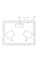
- FIG. 1 is a block diagram showing a schematic configuration of the vehicle air conditioner of the first embodiment.
- FIG. 2 is a cross-sectional view showing a schematic configuration of the dust sensor of the first embodiment.
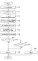
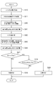
- FIG. 3 is a flowchart showing the procedure of processing executed by the ECU of the first embodiment.
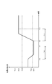
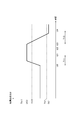
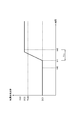
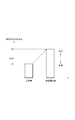
- FIG. 4 is a timing chart showing an operation example of the dust sensor of the first embodiment.
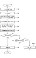
- FIG. 5 is a flowchart showing the procedure of processing executed by the ECU of the modification of the first embodiment.
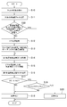
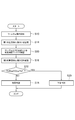
- FIG. 6 is a flowchart showing the procedure of processing executed by the ECU of the second embodiment.
- FIG. 7 is a timing chart showing an operation example of the dust sensor of the second embodiment.
- FIG. 8 is a flowchart showing the procedure of processing executed by the ECU of the third embodiment.
- FIG. 9 is a timing chart showing an operation example of the dust sensor of the third embodiment.
- FIG. 10 is a flowchart showing the procedure of processing executed by the ECU of the first modified example of the third embodiment.
- FIG. 11 is a flowchart showing the procedure of processing executed by the ECU of the second modified example of the third embodiment.
- FIG. 12 is a timing chart showing an operation example of the dust sensor of the second modified example of the third embodiment.
- FIG. 13 is a flowchart showing the procedure of processing executed by the ECU of the fourth embodiment.
- FIG. 14 is a flowchart showing the procedure of processing executed by the ECU of the fifth embodiment.
- FIG. 15 is a timing chart showing an operation example of the dust sensor of the fifth embodiment.
- FIG. 16 is a flowchart showing the procedure of processing executed by the ECU of the sixth embodiment.
- FIG. 17 is a timing chart showing an operation example of the dust sensor of the sixth embodiment.
- the vehicle air conditioner 10 of the present embodiment shown in FIG. 1 is mounted on a vehicle and is an apparatus for performing air conditioning in a vehicle interior.
- the vehicle air conditioner 10 includes an air conditioning unit 20, a dust sensor 30, an operation device 40, a display device 50, and an electronic control unit (ECU) 60.
- ECU electronice control unit
- the air conditioning unit 20 is a main part of the vehicle air conditioner 10, and performs air conditioning of the air taken in from the vehicle interior or the vehicle exterior, and supplies the conditioned air, which is the air conditioned air, to the vehicle interior.
- the air conditioning unit 20 includes a blower storage unit 21, a blower device 22, a connection unit 23, and an air conditioning unit 24.
- the air in the passenger compartment is also referred to as “inner air”
- the air outside the passenger compartment is also referred to as "outside air”.
- the blower storage portion 21 is a portion for taking in air.
- a blower device 22 is accommodated inside the blower accommodating portion 21.
- An inside air intake port 210 and an outside air intake port 211 are formed in the blower housing portion 21.
- the inside air suction port 210 is an opening formed as an inlet of air introduced from the vehicle compartment.
- the space in the passenger compartment and the inside air suction port 210 are connected by a duct (not shown).
- the fresh air suction port 211 is an opening formed as an inlet for air introduced from the outside of the vehicle.
- the space outside the passenger compartment and the outside air intake port 211 are also connected by a duct (not shown).
- An inside / outside air switching door 212 is provided between the inside air inlet 210 and the outside air inlet 211 in the blower housing 21.
- the inside / outside air switching door 212 adjusts the opening degree of each of the inside air inlet 210 and the outside air inlet 211. Specifically, when the inside / outside air switching door 212 is located at the outside air introducing position shown by a solid line in the drawing, the inside air intake port 210 is closed and the outside air intake port 211 is opened. In this case, the air conditioning unit 20 enters an outside air introduction mode in which the outside air is sucked from the outside air inlet 211. In the outside air introduction mode, the atmosphere outside the vehicle is blown out into the vehicle interior.
- the air conditioning unit 20 is in the inside air circulation mode in which the inside air is taken in from the inside air inlet 210.
- the air in the passenger compartment circulates through the air conditioning unit 20 and is blown out into the passenger compartment.
- the opening degree of each of the inside air inlet 210 and the outside air inlet 211 by the inside / outside air switching door 212 the flow rate of air sucked into the air conditioning unit 20 from the inside air inlet 210 and the outside air inlet 211
- the ratio to the flow rate of air drawn into the air conditioning unit 20 can also be adjusted.
- a filter 25 is disposed on the air flow upstream side of the blower device 22 in the blower housing portion 21.
- the filter 25 removes dust, dirt and the like contained in the air flowing in from the inside air inlet 210 and the outside air inlet 211. That is, when the air introduced from the inside air intake port 210 or the outside air intake port 211 passes through the filter 25, clean air from which dust, dust and the like are removed is blown out into the vehicle interior.
- the filter 25 is replaceable.
- the blower device 22 is a device that generates an air flow blown into the vehicle compartment.
- air is drawn into the blower housing 21 from the inside air inlet 210 and the outside air inlet 211.
- the air is blown out into the vehicle compartment through the connection 23 and the air conditioner 24.
- the power supplied to the blower device 22 it is possible to adjust the flow rate of air drawn into the blower housing 21, in other words, the air volume of the conditioned air blown out into the vehicle compartment.
- connection portion 23 is a portion provided as a flow path connecting the blower housing portion 21 and the air conditioning portion 24.
- the connection portion 23 is integrally formed with the blower housing portion 21.
- the air conditioning unit 24 is a part that performs temperature control of air. Inside the air conditioning unit 24, an evaporator for dehumidifying and cooling the air, a heater core for heating the air, an air mix door for adjusting the flow rate of air flowing through the evaporator and the heater core, and the like are arranged.
- a defroster blowout unit 240, a face blowout unit 241, and a foot blowout unit 242 are provided on the air flow direction downstream side of the air conditioning unit 24, respectively.
- the defroster blowout portion 240 is a portion that blows the conditioned air toward the windshield of the vehicle.
- the face blowing portion 241 is a portion that blows the conditioned air toward the face of the vehicle occupant.
- the foot blowing portion 242 is a portion that blows the conditioned air toward the foot of the vehicle occupant.
- a door (not shown) is provided in each of the defroster blowout portion 240, the face blowout portion 241, and the foot blowout portion 242, and the flow rate of air blown out from each blowout portion is adjusted according to the opening degree of the door.
- An air introduction chamber 213 is formed in a portion near the end of the filter 25 in the blower housing 21.
- the air introduction chamber 213 is formed as a space through which the air flowing into the air conditioning unit 20 from the outside of the air conditioning unit 20, more specifically, the air introduced into the blower housing 21 from the outside of the air conditioning unit 20 flows. .
- An opening 214 serving as an air inlet of the air introduction chamber 213 is located above the filter 25 and the dust sensor 30.
- the opening 214 communicates the space around the air conditioning unit 20 with the air introduction chamber 213.
- An opening 215 which is an outlet of air in the air introduction chamber 213 is formed at a position slightly below the filter 25.
- the opening 215 communicates the air introduction chamber 213 with the space on the lower side of the filter 25 in the blower housing 21.
- the positions of the opening 214 and the opening 215 as described above are merely examples.
- the opening 214 and the opening 215 may be formed at positions different from the above.
- the air in the air introduction chamber 213 is discharged to the blower device 22 through the opening 215 by the suction force of the blower device 22.
- external air flows into the air introduction chamber 213 through the opening 214.
- air flows from the opening 214 toward the opening 215.
- the blower storage portion 21 is disposed inside the instrument panel of the vehicle.
- the space inside the instrument panel that is, the space outside the air introduction chamber 213 is connected to the vehicle interior. Therefore, the air flowing into the air introduction chamber 213 from the opening 214 is the air in the vehicle compartment.
- the part in which the air introduction chamber 213 in the air conditioning unit 20 is formed is a part to which the dust sensor 30 is attached.
- the dust sensor 30 is attached to the blower housing 21 from the outside so as to divide the side portion of the air introduction chamber 213.
- the dust sensor 30 measures the concentration of dust containing particles such as PM 2.5 in the intake air.
- the dust sensor 30 has a case 31, a light emitting element 32 and a light receiving element 33.
- An opening 310 is formed in the outer wall of the case 31 facing the air introduction chamber 213.
- a space in the case 31 is an air passage 311 through which the air introduced from the opening 310 passes.
- the light emitting element 32 and the light receiving element 33 are disposed in the air passage 311 in the case 31.
- the light emitting element 32 emits light into the air passage 311. Some of the light emitted from the light emitting element 32 is scattered by dust in the air introduced into the air passage 311.
- the light receiving element 33 receives the scattered light scattered by the dust and outputs an electrical signal according to the amount of light received. That is, the electrical signal output from the light receiving element 33 changes with the concentration of dust contained in the air flowing in the air passage 311.
- the dust sensor 30 outputs an electrical signal output from the light receiving element 33 as a dust concentration detection value.
- the electric signal output from the light receiving element 33 is also referred to as an "output value".
- the operating device 40 illustrated in FIG. 1 is a portion operated by the driver when adjusting the air volume, temperature, and the like of the conditioned air.
- the operating device 40 is disposed, for example, on an instrument panel of a vehicle. In the operation device 40, for example, any one of the outside air introduction mode and the inside air circulation mode can be selected. Further, in the operation device 40, the air volume of the air conditioning air, the temperature of the air conditioning air, the outlet of the air conditioning air, and the like can be set.
- the operating device 40 outputs the operation information to the ECU 60.
- the display device 50 is a portion that displays various information of the vehicle air conditioner 10.
- a touch panel or the like used for a car navigation device of a vehicle can be diverted.
- the display device 50 may be a device provided exclusively for the vehicle air conditioner 10.
- the ECU 60 is mainly configured of a microcomputer having a CPU 61, a memory 62, and the like.
- the ECU 60 acquires operation information from the operation device 40, and drives the air conditioning unit 20 based on the acquired operation information.
- the air conditioning unit 20 generates the conditioned air according to the operation information of the operating device 40, and the conditioned air is blown out into the vehicle interior to perform the air conditioning of the vehicle interior.
- the detection signal of the dust sensor 30 is taken into the ECU 60.
- the ECU 60 acquires dust concentration information based on the detection signal of the dust sensor 30, and displays the acquired dust concentration information on the display device 50.
- the ECU 60 can also open and close windows respectively provided on a plurality of doors of the vehicle. Specifically, the ECU 60 can automatically open and close the windows of the plurality of doors of the vehicle by transmitting the command signal to the window opening and closing device 70 of the vehicle, regardless of the operation of the vehicle occupant. .
- the ECU 60 can communicate with a diagnostic device 80 connected from the outside of the vehicle.
- the diagnostic device 80 can be connected to an external input / output terminal provided in a vehicle or can be detached from the external input / output terminal.
- the diagnosis device 80 is operated by a dealer or the like, and detects the abnormality of the vehicle by software or repairs the detected abnormality by software by connecting and operating the external input / output terminal of the vehicle. Can be Further, the diagnosis device 80 has a screen on which various information can be displayed.
- the diagnosis device 80 is communicably connected to the server device 82 via the network line 81.
- the diagnosis device 80 can acquire various types of information from the server device 82 through the network line 81, and can transmit the acquired information to the ECU 60.
- the information that can be acquired from the server device 82 includes information on the current dust concentration of the atmosphere, and the like.
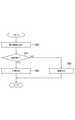
- the ECU 60 executes a failure determination process of determining whether the dust sensor 30 has a failure. That is, in the present embodiment, the ECU 60 functions as a failure determination unit. Next, with reference to FIG. 3, a specific procedure of the failure determination process executed by the ECU 60 will be described. The ECU 60 starts the process shown in FIG. 3 when the diagnostic device 80 is connected to the vehicle.
- the ECU 60 performs notification to prompt replacement of the filter 25 as the process of step S10. Specifically, the ECU 60 requests the diagnostic device 80 to issue a notification prompting replacement of the filter 25. As a result, an image for prompting replacement of the filter 25 is displayed on the screen of the diagnostic device 80, so that a worker who operates the diagnostic device 80 can perform replacement work of the filter. As described above, in the present embodiment, the ECU 60 also functions as a notification unit that performs notification notifying replacement of the filter 25.
- step S10 it may be determined whether notification is to be performed according to the use period of the filter 25 or the like. Further, after detecting that the replacement work of the filter 25 is completed through the operation of the diagnosis device 80, the ECU 60 executes the processing of step S11 and subsequent steps.
- the ECU 60 acquires information on the dust concentration Th1 of the air from the diagnosis device 80 and stores the information in the memory 62 as the process of step S11. Thereafter, the ECU 60 closes the windows of all the doors of the vehicle as the process of step S12, and then sets the air conditioning unit 20 in the inside air circulation mode for a predetermined time T10 as the process of step S13. And the blower device 22 is driven.
- the processes shown in steps S12 and S13 correspond to the interior purification control.
- the ECU 60 acquires the first dust concentration detection value DC1 based on the detection signal output from the dust sensor 30, and stores the first dust concentration detection value DC1 in the memory 62 as the process of step S14. That is, the first dust concentration detection value DC1 corresponds to the dust concentration detected by the dust sensor 30 when the air in the vehicle compartment is clean.
- the ECU 60 opens the window of at least one of the plurality of doors of the vehicle as a process of step S15 following the process of step S14, and then waits for a predetermined time T11.
- the air outside the passenger compartment is introduced into the passenger compartment, so the dust concentration in the passenger compartment, in other words, the dust concentration detected by the dust sensor 30, becomes a value corresponding to the dust concentration in the air.
- the process of step S15 corresponds to air introduction control.
- the ECU 60 acquires the second dust concentration detection value DC2 based on the detection signal output from the dust sensor 30, and stores the second dust concentration detection value DC2 in the memory 62 as the process of step S16. That is, the second dust concentration detection value DC2 is a dust concentration detected by the dust sensor 30 when the dust concentration in the vehicle compartment corresponds to the dust concentration of the air.
- the ECU 60 determines whether the first dust concentration detection value DC1 is equal to or less than the threshold value Th2 as the process of step S17 following the process of step S16.
- the threshold Th2 is set by experiment or the like so that it can be determined whether or not the first dust concentration detection value DC1 indicates the concentration of dust when the air in the vehicle compartment is clean. It is stored in advance in the memory 62.
- step S17 If the ECU 60 makes a negative determination in step S17, that is, if the first dust concentration detection value DC1 exceeds the threshold value Th2, the ECU 60 determines that the detection value DC1 is an abnormal value, and sets dust as the process of step S18. It is determined that the sensor 30 is in a failure state. In the process of step S18, for example, by displaying the failure of the dust sensor 30 on the screen of the diagnosis device 80, the operator of the diagnosis device 80 is made to recognize the failure of the dust sensor 30.
- the ECU 60 determines that the first dust concentration detection value DC1 indicates a normal value. In this case, the ECU 60 determines whether the second dust concentration detection value DC2 satisfies the relationship of “Th10 ⁇ DC2 ⁇ Th11” with respect to the threshold values Th10 and Th11 as the process of step S19.
- the threshold Th10 is set to a value smaller than the dust concentration Th1 of the air by a predetermined value.
- the threshold Th11 is set to a value larger than the dust concentration Th1 of the air by a predetermined value.
- the thresholds Th10 and Th11 are used to determine whether the second dust concentration detection value DC2 is a value near the dust concentration Th1 of the air.
- the ECU 60 makes a negative determination in the process of step S19, that is, if the second dust concentration detection value DC2 is less than the threshold Th10 or exceeds the threshold Th11, the second dust concentration detection value DC2 is an abnormal value. It is determined that In this case, the ECU 60 determines that the dust sensor 30 is in a failure state as the process of step S18.
- the ECU 60 makes an affirmative determination in the process of step S19, that is, if the second dust concentration detection value DC2 satisfies the relationship of “Th10 ⁇ DC2 ⁇ Th11”, the second dust concentration detection value DC2 is a normal value. Determine that there is. In this case, the ECU 60 determines that the dust sensor 30 is in the normal state as the process of step S20. In the process of step S20, for example, by displaying that the dust sensor 30 is normal on the screen of the diagnosis device 80, the operator who operates the diagnosis device 80 is made to recognize that the dust sensor 30 has no abnormality.
- the ECU 60 starts the process shown in FIG. 3 at time t10, for example, the ECU 60 first sets the windows of all the doors of the vehicle to the closed state and sets the inside air circulation mode In the state in which the air conditioning unit 20 is set, the in-room purification control for driving the blower device 22 is executed. Since the air in the passenger compartment is purified by the execution of the interior purification control, the detection value of the dust sensor 30 gradually decreases after time t10.
- the detection value of the dust sensor 30 is a value when air in the vehicle compartment is clean. Converge. Then, at time t11, the ECU 60 acquires the detection value of the dust sensor 30 as the first dust concentration detection value DC1.
- the ECU 60 determines that the first dust concentration detection value DC1 is a normal value. Therefore, at time t12 thereafter, the ECU 60 executes air introduction control for opening at least one of the plurality of doors of the vehicle. Since the air is introduced into the vehicle compartment by the execution of the air introduction control, the detected value of the dust sensor 30 gradually increases after time t12. Further, since the air introduction control is continued from time t12 to time t13 when the predetermined time T11 elapses, the detection value of the dust sensor 30 converges to a value corresponding to the dust concentration of the air. Then, at time t13, the ECU 60 acquires the detection value of the dust sensor 30 as the second dust concentration detection value DC2.
- the second dust concentration detection value DC2 is normal because the second dust concentration detection value DC2 satisfies the relationship “Th10 ⁇ DC2 ⁇ Th11” with respect to the threshold values Th10 and Th11. It is determined that it is a value. From the above, the ECU 60 determines that the dust sensor 30 is in the normal state.
- the ECU 60 determines the presence or absence of a failure of the dust sensor 30 based on the detection value of the dust sensor 30 after execution of the interior purification control and the detection value of the dust sensor after execution of the air introduction control. Specifically, the ECU 60 determines the presence or absence of a failure of the dust sensor 30 by executing the interior purification control, and then determines the presence or absence of a failure of the dust sensor 30 by executing air introduction control. Thereby, the presence or absence of a failure of the dust sensor 30 can be determined.
- the ECU 60 performs notification to urge replacement of the filter 25 provided in the air conditioning unit 20 before executing the interior purification control.
- the interior purification control is performed after the filter 25 is replaced, the interior of the vehicle is more easily cleaned. Therefore, it is possible to accurately detect the first dust concentration detection value DC1, which is the concentration of dust in a state where the interior of the vehicle has been cleaned, and as a result, it is possible to improve the determination accuracy of the failure of the dust sensor 30. it can.
- step S11 the ECU 60 of the present modification example closes the windows of all the doors of the vehicle in the period from the present to a predetermined time before as the process of step S30. Then, it is determined whether the air conditioning unit 20 is set to the internal air circulation mode and the blower device 22 continues to be driven.
- the ECU 60 makes an affirmative determination in the process of step S30, the ECU 60 executes the processes of step S14 and subsequent steps without executing the processes of steps S12 and S13.
- the ECU 60 makes a negative determination in the process of step S30, it executes the process of step S12 and subsequent steps.
- the in-room purification control of steps S12 and S13 by the ECU 60 It is determined whether the dust sensor 30 has a failure or not without being executed. Therefore, the failure determination result of the dust sensor 30 can be obtained earlier.
- the ECU 60 of the first embodiment executes the air introduction control after executing the interior purification control.
- the ECU 60 of the present embodiment differs from the ECU 60 of the first embodiment in that the interior purification control is performed after the atmosphere introduction control is performed.
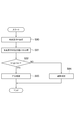
- the ECU 60 of the present embodiment executes the process shown in FIG. 6 instead of the process shown in FIG.
- the ECU 60 opens the window of at least one door of the plurality of doors of the vehicle as the process of step S40, and then predetermined time T11 Just wait. Thereafter, the ECU 60 acquires the second dust concentration detection value DC2 based on the detection signal output from the dust sensor 30, and stores the second dust concentration detection value DC2 in the memory 62 as the process of step S41.
- the ECU 60 After closing the windows of all the doors of the vehicle as the process of step S42 following the process of step S41, the ECU 60 sets the inside air temperature of the air conditioning unit 20 for a predetermined time T10 as the process of step S43. The circulation mode is set and the blower device 22 is driven. Then, after completing the process of step S43, the ECU 60 acquires the first dust concentration detection value DC1 based on the detection signal output from the dust sensor 30 as the process of step S44, and stores this in the memory 62. . Thereafter, the ECU 60 executes the processing of step S17 and subsequent steps.
- the ECU 60 starts the process shown in FIG. 3 at time t20, for example, the ECU 60 first opens the window of at least one of the plurality of doors of the vehicle. Perform air introduction control. Since the air is introduced into the vehicle compartment by the execution of the air introduction control, the detected value of the dust sensor 30 gradually increases after time t20. Further, since the air introduction control is continued for a period from time t20 to time t21 when the predetermined time T11 elapses, the detection value of the dust sensor 30 converges to a value corresponding to the dust concentration of the air. Then, at time t22, the ECU 60 acquires the detection value of the dust sensor 30 as the second dust concentration detection value DC2.
- the second dust concentration detection value DC2 is normal because the second dust concentration detection value DC2 satisfies the relationship “Th10 ⁇ DC2 ⁇ Th11” with respect to the threshold values Th10 and Th11. It is determined that it is a value. Thereafter, at time t23, the ECU 60 controls the interior of the room to drive the blower device 22 with the windows of all the doors of the vehicle closed and the air conditioning unit 20 set to the internal air circulation mode. Run. Since the air in the passenger compartment is purified by the execution of the interior purification control, the detection value of the dust sensor 30 gradually decreases after time t23.
- the detection value of the dust sensor 30 is a value when the air in the vehicle compartment is clean. Converge. Then, at time t24, the ECU 60 acquires the detection value of the dust sensor 30 as the first dust concentration detection value DC1.
- the ECU 60 determines that the first dust concentration detection value DC1 is a normal value. From the above, the ECU 60 determines that the dust sensor 30 is in the normal state. According to the vehicle air conditioner 10 of the present embodiment described above, it is possible to obtain the same or similar operation and effect as the vehicle air conditioner 10 of the first embodiment.
- the vehicle air conditioner 10 of the present embodiment determines the presence or absence of a failure of the dust sensor 30 by using sample air instead of the air.
- the sample air indicates air in which the concentration of contained dust is known.
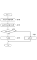
- the ECU 60 executes the process shown in FIG. 8 instead of the process shown in FIG.
- a sample air supply device for supplying sample air to the dust sensor 30 is installed near the opening 214 of the air introduction chamber 213 by an operator or the like before the process shown in FIG. 8 is performed.
- the ECU 60 supplies sample air to the dust sensor 30 as the process of step S50, and then waits for a predetermined time T11. Specifically, the ECU 60 supplies sample air to the dust sensor 30 by displaying an instruction for driving the sample air supply device on the screen of the diagnosis device 80 or directly operating the sample air supply device. .
- the process of step S50 corresponds to sample air supply control. Thereafter, the ECU 60 executes the processing of step S16 and subsequent steps.
- the threshold values Th10 and Th11 used in the process of step S19 are input by, for example, the diagnosis device 80 or the like so that it can be determined whether or not the second dust concentration detection value DC2 indicates the dust concentration of the sample air.
- the value to be used is used.
- the threshold Th10 is set to a value smaller than the input value of the diagnosis device 80 by a predetermined value.
- the threshold Th11 is set to a value larger than the input value of the diagnosis device 80 by a predetermined value.
- the ECU 60 executes sample air supply control at time t32. Since the sample air is supplied to the dust sensor 30 by execution of the sample air supply control, the detection value of the dust sensor 30 gradually increases after time t32. Further, since the sample air supply control is continued from time t32 to time t33 when the predetermined time T11 elapses, the detection value of the dust sensor 30 converges to a value corresponding to the dust concentration of the sample air. Then, at time t33, the ECU 60 acquires the detection value of the dust sensor 30 as the second dust concentration detection value DC2.
- the second dust concentration detection value DC2 is normal because the second dust concentration detection value DC2 satisfies the relationship “Th10 ⁇ DC2 ⁇ Th11” with respect to the threshold values Th10 and Th11. It is determined that it is a value. From the above, the ECU 60 determines that the dust sensor 30 is in the normal state.
- the actions and effects shown in the following (3) and (4) can be obtained.
- the ECU 60 After executing the interior purification control, the ECU 60 determines the presence or absence of a failure of the dust sensor 30 by executing the sample air supply control. As a result, only the sample air can be easily supplied to the dust sensor 30, and as a result, the determination accuracy of the failure of the dust sensor 30 can be improved.
- step S10 After executing the process of step S10, the ECU 60 of the present modification example closes the windows of all the doors of the vehicle in the period from the present to a predetermined time before as the process of step S60. Then, it is determined whether the air conditioning unit 20 is set to the internal air circulation mode and the blower device 22 continues to be driven.
- the ECU 60 makes an affirmative determination in the process of step S60, the ECU 60 executes the processes of step S14 and subsequent steps without executing the processes of steps S12 and S13.
- the ECU 60 makes a negative determination in the process of step S30, it executes the process of step S12 and subsequent steps.
- the in-room purification control of steps S12 and S13 by the ECU 60 It is determined whether the dust sensor 30 has a failure or not without being executed. Therefore, it is possible to obtain the determination result earlier.
- the ECU 60 of the present modification executes the process shown in FIG. 11 instead of the process shown in FIG. As shown in FIG. 11, the ECU 60 sequentially executes the processes of steps S10, S14, S50, and S16.
- the first dust concentration detection value DC1 acquired by the ECU 60 in the process of step S14 is the concentration of dust in the vehicle interior in a state in which the interior purification control is not performed, that is, the concentration of dust in the real environment.
- the first dust concentration detection value DC1 corresponds to the detection value of the dust concentration in the actual environment.
- the ECU 60 determines whether the second dust concentration detection value DC2 satisfies the relationship of “Th30 ⁇ DC2 ⁇ Th31” with respect to the threshold values Th30 and Th31 as the process of step S70. Do.
- the threshold value obtained by adding the first dust concentration detection value DC1 to the dust concentration of the sample air is used as the reference concentration value, whether the second dust concentration detection value DC2 is a value near the reference concentration value Is set so that it can be determined.
- the threshold value Th30 is set to a value smaller than the reference density value by a predetermined value.
- the threshold Th11 is set to a value larger than the reference density value by a predetermined value.
- step S70 determines that the dust sensor 30 is in a failure state as the process of step S18.
- the ECU 60 makes an affirmative determination in the process of step S70, it determines that the dust sensor 30 is in the normal state as the process of step S20.
- the operation example of the vehicle air conditioner 10 of this modification is demonstrated.
- the ECU 60 executes sample air supply control at time t41. Since the sample air is supplied to the dust sensor 30 by the execution of the sample air supply control, the detection value of the dust sensor 30 gradually increases after time t41. Further, since the sample air supply control is continued from time t41 to time t42 when the predetermined time T11 elapses, the detection value of the dust sensor 30 is the dust concentration of the sample air in the first dust concentration detection value DC1. It converges to the added value. Then, at time t42, the ECU 60 acquires the detection value of the dust sensor 30 as the second dust concentration detection value DC2.
- the second dust concentration detection value DC2 is normal because the second dust concentration detection value DC2 satisfies the relationship “Th30 ⁇ DC2 ⁇ Th31” with respect to the threshold values Th30 and Th31. It is determined that it is a value. From the above, the ECU 60 determines that the dust sensor 30 is in the normal state.
- the presence of failure of the dust sensor 30 is determined based on the signal output from the light receiving element 33 of the dust sensor 30 when the dust sensor 30 is irradiated with light.
- the ECU 60 executes the process shown in FIG. Before the process shown in FIG. 13 is performed, a light emitting device 90 is installed by an operator or the like in the vicinity of the opening 214 of the air introduction chamber 213, as shown by a broken line in FIG.
- the ECU 60 first turns on the light emitting device 90 as the process of step S80. Specifically, the ECU 60 turns on the light emitting device 90 by displaying an instruction to turn on the light emitting device 90 on the screen of the diagnostic device 80 or directly operating the light emitting device 90.
- the light emitting device 90 is turned on, the light is received by the light receiving element 33 through the opening 214 of the air introduction chamber 213 and the opening 310 of the case 31 of the dust sensor 30. That is, since the amount of light received by the light receiving element 33 increases, the output value of the light receiving element 33 increases.
- the process of step S80 corresponds to light amount adjustment control for changing the light amount received by the light receiving element 33.
- the ECU 60 determines whether the light emitted from the light emitting device 90 is detected by the light receiving element 33 as the process of step S81 following the process of step S80. Specifically, the ECU 60 determines whether or not the light receiving element 33 has detected light based on whether or not the output value of the light receiving element 33 is equal to or greater than a predetermined threshold value. When the ECU 60 makes an affirmative determination in the process of step S81, it determines that the dust sensor 30 is in a normal state as the process of step S82. On the other hand, when the ECU 60 makes a negative determination in the process of step S81, it determines that the dust sensor 30 is in a failure state as the process of step S83.
- the ECU 60 determines the presence or absence of a failure of the dust sensor 30 based on the output value of the light receiving element after execution of the light amount adjustment control. Thereby, the presence or absence of a failure of the dust sensor 30 can be determined.
- the presence or absence of a failure of the dust sensor 30 is determined based on a signal output from the light receiving element 33 when the light emitting element 32 of the dust sensor 30 is turned on.
- the ECU 60 executes the process shown in FIG. As shown in FIG. 14, the ECU 60 first turns on the light emitting element 32 as the process of step S90, and then acquires the output value V1 of the light receiving element 33 as the process of step S91.
- the process of step S90 corresponds to light emission control.
- the ECU 60 determines whether the output value V1 of the light receiving element 33 is equal to or greater than a predetermined threshold value Vth1.
- the threshold value Vth1 is set by experiments or the like so as to be a value that can guarantee the operation of the dust sensor 30, and is stored in advance in the memory 62.
- the threshold value Vth1 is set to a value smaller by a predetermined value than the initial value, for example, when the output value of the light receiving element 33 at the time of factory shipment is set as the initial value.
- step S92 determines that the dust sensor 30 is in a normal state as the process of step S93.
- step S92 determines that the dust sensor 30 is in a failure state as the process of step S94.
- the vehicle air conditioner 10 of the present embodiment will be described.
- the output value of the light receiving element 33 at the time of shipment from the factory is set to the initial value VI
- the output value of the light receiving element 33 gradually decreases with the passage of time. This is due to the aged deterioration of the light emitting element 32 and the light receiving element 33, and the accumulation of dust, dust and the like on them.
- the ECU 60 determines that the dust sensor 30 is in a failure state when the current output value V1 of the light receiving element 33 is less than the threshold value Vth1.
- the ECU 60 acquires the output value V1 of the light receiving element 33 and, based on whether the acquired output value V1 of the light receiving element 33 is equal to or less than the threshold value Vth1, Determine if there is a failure. Thereby, the presence or absence of a failure of the dust sensor 30 can be determined.
- the presence or absence of a failure of the dust sensor 30 is determined based on the signal output from the light receiving element 33 when the luminance of the light emitting element 32 of the dust sensor 30 is adjusted.
- the ECU 60 executes the process shown in FIG. As shown in FIG. 16, the ECU 60 first adjusts the brightness of the light emitting element 32 as the process of step S100, specifically, after increasing the brightness of the light emitting element 32 more than the brightness in normal use, the step As a process of S101, the output value V2 of the light receiving element 33 is acquired.
- the process of step S100 corresponds to brightness adjustment control.
- the ECU 60 determines whether the output value V2 of the light receiving element 33 is equal to or greater than a predetermined threshold value Vth2.
- the threshold value Vth2 is set by experiment or the like so that it can be determined whether or not the output value of the light receiving element 33 is fixed, and is stored in advance in the memory 62.
- the threshold value Vth2 is set to a value larger by a predetermined value than the initial value, for example, when the output value of the light receiving element 33 at the time of factory shipment is set as the initial value.
- step S102 determines that the dust sensor 30 is in a normal state as the process of step S103.
- the ECU 60 makes a negative determination in the process of step S102, it determines that the dust sensor 30 is in a failure state as the process of step S104.
- the vehicle air conditioner 10 of the present embodiment when the output value of the light receiving element 33 at the time of shipment from the factory is set to the initial value VI, if the light receiving element 33 is normal, the luminance of the light emitting element 32 is increased more than the luminance in normal use. The output value of the light receiving element 33 is increased from the normal value. Therefore, when the brightness adjustment control is executed, the ECU 60 determines that the dust sensor 30 is in the normal state when the current output value V2 of the light receiving element 33 is equal to or more than the threshold value Vth2.
- the ECU 60 acquires the output value V2 of the light receiving element 33 when executing the brightness adjustment control, and the dust sensor 30 based on whether the acquired output value V2 of the light receiving element 33 is abnormal at the threshold value Vth2. To determine the presence or absence of Thereby, the presence or absence of a failure of the dust sensor 30 can be determined.
- each embodiment can also be implemented in the following modes.
- the position of the dust sensor 30 in the air conditioning unit 20 can be changed as appropriate.
- the means and / or functions provided by the ECU 60 can be provided by software stored in a substantial memory and a computer that executes the software, only software, only hardware, or a combination thereof.
- the ECU 60 when the ECU 60 is provided by an electronic circuit that is hardware, it can be provided by a digital circuit or an analog circuit that includes a number of logic circuits.
- the process of closing the windows of all the doors of the vehicle is illustrated as one process of the purification control inside the vehicle, but for example, the process of closing the door itself of the vehicle is executed. It is also good.
- the purification processing in the passenger compartment may be control for driving the blower device 22 in a state where the space inside the passenger compartment is closed and the air conditioning unit 20 is set to the inside air circulation mode.
- atmosphere introduction control the door itself of a vehicle is made into an open state, for example A process, a process of setting the air conditioning unit 20 to the outside air introduction mode, or the like may be executed.
- the atmosphere introduction control may be any control that introduces the atmosphere into the vehicle interior by opening the space in the vehicle interior.
- the present disclosure is not limited to the above specific example. Those skilled in the art may appropriately modify the above-described specific example as long as the features of the present disclosure are included.
- the elements included in the specific examples described above, and the arrangement, conditions, shape, and the like of the elements are not limited to those illustrated, and can be changed as appropriate.
- the elements included in the above-described specific examples can be appropriately changed in combination as long as no technical contradiction arises.
Abstract
A vehicular air conditioning device (10) that comprises an air conditioning unit (20), a dust sensor (30), and a failure determination part (60). The air conditioning unit air conditions the interior of a vehicle. The dust sensor: detects the concentration of dust included in air that flows through the air conditioning unit; and outputs a detection value that corresponds to the detected dust concentration. The failure determination part: executes prescribed control that alters the detection value from the dust sensor; and determines, on the basis of the detection value from the dust sensor after execution of the prescribed control, whether the dust sensor has failed.
Description
本出願は、2017年10月13日に出願された日本国特許出願2017-199649号に基づくものであって、その優先権の利益を主張するものであり、その特許出願の全ての内容が、参照により本明細書に組み込まれる。
This application is based on Japanese Patent Application No. 2017-199649 filed on October 13, 2017, and claims the benefit of its priority, and the entire contents of that patent application are: Incorporated herein by reference.
本開示は、埃センサを備える車両用空調装置に関する。
The present disclosure relates to a vehicle air conditioner provided with a dust sensor.
従来、下記の特許文献1に記載の車両用空調装置がある。特許文献1に記載の車両用空調装置は、車室内又は車室外から取り込んだ空気の温度を調整するとともに、温度の調整された空気である空調風を車室内に向けて吹き出している。特許文献1に記載の車両用空調装置では、空調ユニット内に設けられたヒータコアやエバポレータにより空気の温度が調整されている。
Conventionally, there is a vehicle air conditioner described in Patent Document 1 below. The vehicle air conditioner described in Patent Document 1 adjusts the temperature of the air taken in from the vehicle interior or the vehicle exterior, and blows the conditioned air, which is the temperature-adjusted air, into the vehicle interior. In the vehicle air conditioner described in Patent Document 1, the temperature of air is adjusted by the heater core and the evaporator provided in the air conditioning unit.
本発明者らは、空気中を漂う粒子状物質(例えばPM2.5)等の埃の濃度を測定する機能を車両用空調装置に付与することについて検討を進めている。例えば埃の濃度を光学的に測定する埃センサを車両用空調装置に設けた上で、車室内から空調ユニットに吸い込まれる空気の一部を埃センサに流れるような構造にすれば、車室内の空気中の埃の濃度を測定することが可能となる。しかしながら、このような埃センサが故障すると、埃の濃度を誤検出したり、埃自体を検出できなかったりする等の不都合が生じる可能性がある。
The inventors of the present invention have been examining providing a vehicle air conditioner with a function of measuring the concentration of dust such as particulate matter (for example, PM 2.5) floating in the air. For example, if a dust sensor for optically measuring the concentration of dust is provided in a vehicle air conditioner, and a portion of the air sucked from the vehicle compartment into the air conditioning unit is made to flow to the dust sensor, It is possible to measure the concentration of dust in the air. However, if such a dust sensor fails, problems such as erroneous detection of the dust concentration or failure to detect the dust itself may occur.
本開示の目的は、埃センサの故障の有無を判定することの可能な車両用空調装置を提供することにある。
An object of the present disclosure is to provide a vehicle air conditioner capable of determining the presence or absence of a dust sensor failure.
本開示の一態様による車両用空調装置は、空調ユニットと、埃センサと、故障判定部とを備える。空調ユニットは、車室内の空調を行う。埃センサは、空調ユニットを流れる空気に含まれる埃の濃度を検出するとともに、検出された埃の濃度に応じた検出値を出力する。故障判定部は、埃センサの検出値を変化させる所定の制御を実行するとともに、所定の制御の実行後の埃センサの検出値に基づいて埃センサの故障の有無を判定する。
A vehicle air conditioner according to an aspect of the present disclosure includes an air conditioning unit, a dust sensor, and a failure determination unit. The air conditioning unit air-conditions the passenger compartment. The dust sensor detects the concentration of dust contained in the air flowing through the air conditioning unit, and outputs a detection value corresponding to the detected dust concentration. The failure determination unit executes predetermined control for changing the detection value of the dust sensor, and determines the presence or absence of the failure of the dust sensor based on the detection value of the dust sensor after execution of the predetermined control.
この構成によれば、埃センサの故障の有無を判定することができる。
According to this configuration, it is possible to determine the presence or absence of a failure of the dust sensor.
以下、車両用空調装置の実施形態について図面を参照しながら説明する。説明の理解を容易にするため、各図面において同一の構成要素に対しては可能な限り同一の符号を付して、重複する説明は省略する。
<第1実施形態>
はじめに、図1~図4を参照して、第1実施形態の車両用空調装置について説明する。 Hereinafter, embodiments of a vehicle air conditioner will be described with reference to the drawings. In order to facilitate understanding of the description, the same constituent elements in the drawings are denoted by the same reference numerals as much as possible, and redundant description will be omitted.
First Embodiment
First, the vehicle air conditioner according to the first embodiment will be described with reference to FIGS. 1 to 4.
図1に示される本実施形態の車両用空調装置10は、車両に搭載されており、車室内の空調を行うための装置である。図1に示されるように、車両用空調装置10は、空調ユニット20と、埃センサ30と、操作装置40と、表示装置50と、ECU(Electronic Control Unit)60とを備えている。
The vehicle air conditioner 10 of the present embodiment shown in FIG. 1 is mounted on a vehicle and is an apparatus for performing air conditioning in a vehicle interior. As shown in FIG. 1, the vehicle air conditioner 10 includes an air conditioning unit 20, a dust sensor 30, an operation device 40, a display device 50, and an electronic control unit (ECU) 60.
空調ユニット20は、車両用空調装置10の主要部分であって、車室内又は車室外から取り込んだ空気の空調を行うとともに、空調された空気である空調風を車室内に供給するものである。空調ユニット20は、ブロワ収納部21と、ブロワ装置22と、接続部23と、空調部24とを備えている。なお、以下では、便宜上、車室内の空気を「内気」とも称するとともに、車室外の空気を「外気」とも称する。
The air conditioning unit 20 is a main part of the vehicle air conditioner 10, and performs air conditioning of the air taken in from the vehicle interior or the vehicle exterior, and supplies the conditioned air, which is the air conditioned air, to the vehicle interior. The air conditioning unit 20 includes a blower storage unit 21, a blower device 22, a connection unit 23, and an air conditioning unit 24. In the following, for convenience, the air in the passenger compartment is also referred to as "inner air", and the air outside the passenger compartment is also referred to as "outside air".
ブロワ収納部21は、空気を取り込む部分である。ブロワ収納部21の内部には、ブロワ装置22が収容されている。ブロワ収納部21には、内気吸入口210と外気吸入口211とが形成されている。内気吸入口210は、車室内から導入される空気の入口として形成された開口である。車室内の空間と内気吸入口210との間は、不図示のダクトにより接続されている。外気吸入口211は、車両の外から導入される空気の入口として形成された開口である。車室外の空間と外気吸入口211との間も、不図示のダクトによって接続されている。
The blower storage portion 21 is a portion for taking in air. A blower device 22 is accommodated inside the blower accommodating portion 21. An inside air intake port 210 and an outside air intake port 211 are formed in the blower housing portion 21. The inside air suction port 210 is an opening formed as an inlet of air introduced from the vehicle compartment. The space in the passenger compartment and the inside air suction port 210 are connected by a duct (not shown). The fresh air suction port 211 is an opening formed as an inlet for air introduced from the outside of the vehicle. The space outside the passenger compartment and the outside air intake port 211 are also connected by a duct (not shown).
ブロワ収納部21のうち、内気吸入口210と外気吸入口211との間には、内外気切換ドア212が設けられている。内外気切換ドア212は、内気吸入口210及び外気吸入口211のそれぞれの開度を調整する。具体的には、内外気切換ドア212が図中に実線で示される外気導入位置に位置している場合、内気吸入口210が閉塞されるとともに、外気吸入口211が開口される。この場合、空調ユニット20は、外気吸入口211から外気を吸い込む外気導入モードとなる。外気導入モードでは、車室外の大気が車室内に吹き出されることになる。一方、内外気切換ドア212が図中の破線で示される内気導入位置に位置している場合、外気吸入口211が閉塞されるとともに、内気吸入口210が開口される。この場合、空調ユニット20は、内気吸入口210から内気を取り込む内気循環モードとなる。内気循環モードでは、車室内の空気が空調ユニット20を循環して車室内に吹き出されることになる。また、内外気切換ドア212により内気吸入口210及び外気吸入口211のそれぞれの開度が調整されることにより、内気吸入口210から空調ユニット20に吸い込まれる空気の流量と、外気吸入口211から空調ユニット20に吸い込まれる空気の流量との比率も調整することが可能である。
An inside / outside air switching door 212 is provided between the inside air inlet 210 and the outside air inlet 211 in the blower housing 21. The inside / outside air switching door 212 adjusts the opening degree of each of the inside air inlet 210 and the outside air inlet 211. Specifically, when the inside / outside air switching door 212 is located at the outside air introducing position shown by a solid line in the drawing, the inside air intake port 210 is closed and the outside air intake port 211 is opened. In this case, the air conditioning unit 20 enters an outside air introduction mode in which the outside air is sucked from the outside air inlet 211. In the outside air introduction mode, the atmosphere outside the vehicle is blown out into the vehicle interior. On the other hand, when the inside / outside air switching door 212 is located at the inside air introducing position shown by the broken line in the figure, the outside air inlet 211 is closed and the inside air inlet 210 is opened. In this case, the air conditioning unit 20 is in the inside air circulation mode in which the inside air is taken in from the inside air inlet 210. In the inside air circulation mode, the air in the passenger compartment circulates through the air conditioning unit 20 and is blown out into the passenger compartment. Further, by adjusting the opening degree of each of the inside air inlet 210 and the outside air inlet 211 by the inside / outside air switching door 212, the flow rate of air sucked into the air conditioning unit 20 from the inside air inlet 210 and the outside air inlet 211 The ratio to the flow rate of air drawn into the air conditioning unit 20 can also be adjusted.
ブロワ収納部21においてブロワ装置22よりも空気流れ上流側には、フィルタ25が配置されている。フィルタ25は、内気吸入口210や外気吸入口211から流入した空気に含まれる埃や塵等を除去する。すなわち、内気吸入口210や外気吸入口211から導入された空気がフィルタ25を通過することにより、埃や塵等が除去された清浄な空気が車室内に吹き出されるようになっている。なお、フィルタ25は、交換可能である。
A filter 25 is disposed on the air flow upstream side of the blower device 22 in the blower housing portion 21. The filter 25 removes dust, dirt and the like contained in the air flowing in from the inside air inlet 210 and the outside air inlet 211. That is, when the air introduced from the inside air intake port 210 or the outside air intake port 211 passes through the filter 25, clean air from which dust, dust and the like are removed is blown out into the vehicle interior. The filter 25 is replaceable.
ブロワ装置22は、車室内に送風される空気流を生成する装置である。電力の供給に基づきブロワ装置22が駆動されると、内気吸入口210や外気吸入口211からブロワ収納部21の内部に空気が引き込まれる。当該空気は、接続部23及び空調部24を通じて車室内に吹き出される。ブロワ装置22に供給される電力の調整により、ブロワ収納部21に引き込まれる空気の流量、換言すれば車室内に吹き出される空調風の風量を調整することが可能となっている。
The blower device 22 is a device that generates an air flow blown into the vehicle compartment. When the blower device 22 is driven based on the supply of power, air is drawn into the blower housing 21 from the inside air inlet 210 and the outside air inlet 211. The air is blown out into the vehicle compartment through the connection 23 and the air conditioner 24. By adjusting the power supplied to the blower device 22, it is possible to adjust the flow rate of air drawn into the blower housing 21, in other words, the air volume of the conditioned air blown out into the vehicle compartment.
接続部23は、ブロワ収納部21と空調部24との間を繋ぐ流路として設けられた部分である。接続部23は、ブロワ収納部21と一体的に形成されている。
空調部24は、空気の温度調節を行う部分である。空調部24の内部には、空気の除湿及び冷却を行うエバポレータ、空気の加熱を行うヒータコア、エバポレータ及びヒータコアのそれぞれを流れる空気の流量を調整するエアミックスドア等が配置されている。 Theconnection portion 23 is a portion provided as a flow path connecting the blower housing portion 21 and the air conditioning portion 24. The connection portion 23 is integrally formed with the blower housing portion 21.
Theair conditioning unit 24 is a part that performs temperature control of air. Inside the air conditioning unit 24, an evaporator for dehumidifying and cooling the air, a heater core for heating the air, an air mix door for adjusting the flow rate of air flowing through the evaporator and the heater core, and the like are arranged.
空調部24は、空気の温度調節を行う部分である。空調部24の内部には、空気の除湿及び冷却を行うエバポレータ、空気の加熱を行うヒータコア、エバポレータ及びヒータコアのそれぞれを流れる空気の流量を調整するエアミックスドア等が配置されている。 The
The
空調部24における空気の流れ方向下流側には、デフロスタ吹き出し部240、フェイス吹き出し部241、及びフット吹き出し部242がそれぞれ設けられている。デフロスタ吹き出し部240は、車両のフロントガラスに向けて空調風を吹き出す部分である。フェイス吹き出し部241は、車両の乗員の顔に向けて空調風を吹き出す部分である。フット吹き出し部242は、車両の乗員の足元に向けて空調風を吹き出す部分である。デフロスタ吹き出し部240、フェイス吹き出し部241、及びフット吹き出し部242のそれぞれには不図示のドアが設けられており、ドアの開度によってそれぞれの吹き出し部から吹き出される空気の流量が調整される。尚、空調部24の構造としては公知のものを採用し得るので、その具体的な図示や説明については省略する。
A defroster blowout unit 240, a face blowout unit 241, and a foot blowout unit 242 are provided on the air flow direction downstream side of the air conditioning unit 24, respectively. The defroster blowout portion 240 is a portion that blows the conditioned air toward the windshield of the vehicle. The face blowing portion 241 is a portion that blows the conditioned air toward the face of the vehicle occupant. The foot blowing portion 242 is a portion that blows the conditioned air toward the foot of the vehicle occupant. A door (not shown) is provided in each of the defroster blowout portion 240, the face blowout portion 241, and the foot blowout portion 242, and the flow rate of air blown out from each blowout portion is adjusted according to the opening degree of the door. In addition, since a well-known thing can be employ | adopted as a structure of the air conditioning part 24, it abbreviate | omits about the specific illustration and description.
ブロワ収納部21におけるフィルタ25の端部近傍となる部分には、空気導入室213が形成されている。空気導入室213は、空調ユニット20の外側から空調ユニット20の内部に流れる空気、より詳細には空調ユニット20の外側からブロワ収納部21の内部に導入される空気が流れる空間として形成されている。
An air introduction chamber 213 is formed in a portion near the end of the filter 25 in the blower housing 21. The air introduction chamber 213 is formed as a space through which the air flowing into the air conditioning unit 20 from the outside of the air conditioning unit 20, more specifically, the air introduced into the blower housing 21 from the outside of the air conditioning unit 20 flows. .
空気導入室213において空気の流入口となる開口部214は、フィルタ25や埃センサ30よりも上方側に位置している。開口部214は、空調ユニット20の周囲の空間と、空気導入室213との間を連通させている。空気導入室213において空気の流出口となる開口部215は、フィルタ25よりも僅かに下方側となる位置に形成されている。開口部215は、空気導入室213と、ブロワ収納部21におけるフィルタ25よりも下方側の空間との間を連通させている。尚、上記のような開口部214や開口部215の位置はあくまで一例である。開口部214や開口部215は、それぞれ上記とは異なる位置に形成されていてもよい。
An opening 214 serving as an air inlet of the air introduction chamber 213 is located above the filter 25 and the dust sensor 30. The opening 214 communicates the space around the air conditioning unit 20 with the air introduction chamber 213. An opening 215 which is an outlet of air in the air introduction chamber 213 is formed at a position slightly below the filter 25. The opening 215 communicates the air introduction chamber 213 with the space on the lower side of the filter 25 in the blower housing 21. The positions of the opening 214 and the opening 215 as described above are merely examples. The opening 214 and the opening 215 may be formed at positions different from the above.
ブロワ装置22が駆動されているときには、ブロワ装置22の吸引力により、空気導入室213の空気は開口部215を通ってブロワ装置22側に排出される。これを補うように、外部の空気は開口部214を通って空気導入室213に流入する。このため、空気導入室213の内部では、開口部214から開口部215に向かって空気が流れることとなる。
When the blower device 22 is driven, the air in the air introduction chamber 213 is discharged to the blower device 22 through the opening 215 by the suction force of the blower device 22. To compensate for this, external air flows into the air introduction chamber 213 through the opening 214. For this reason, inside the air introduction chamber 213, air flows from the opening 214 toward the opening 215.
ブロワ収納部21は、車両のインストルメントパネルの内側に配置されている。インストルメントパネルの内側の空間、すなわち、空気導入室213の外側の空間は、車室内と繋がっている。このため、開口部214から空気導入室213に流入する空気は、車室内の空気となっている。
The blower storage portion 21 is disposed inside the instrument panel of the vehicle. The space inside the instrument panel, that is, the space outside the air introduction chamber 213 is connected to the vehicle interior. Therefore, the air flowing into the air introduction chamber 213 from the opening 214 is the air in the vehicle compartment.
空調ユニット20における空気導入室213が形成されている部分は、埃センサ30が取り付けられる部分となっている。埃センサ30は、空気導入室213の側方の部分を区画するように、ブロワ収納部21に対して外側から取り付けられている。
埃センサ30は、吸気中のPM2.5等の粒子を含む埃の濃度を測定する。具体的には、図2に示されるように、埃センサ30は、ケース31と、発光素子32と、受光素子33とを有している。ケース31における空気導入室213に面する外壁には、開口部310が形成されている。ケース31内の空間は、この開口部310から導入される空気が通過する空気通路311となっている。発光素子32及び受光素子33は、ケース31内の空気通路311に配置されている。発光素子32は、空気通路311内に光を発する。発光素子32から発せられた光の一部は、空気通路311内に導入された空気中の埃により散乱される。受光素子33は、埃により散乱された散乱光を受光するとともに、受光した光量に応じた電気信号を出力する。すなわち、受光素子33から出力される電気信号は、空気通路311内を流れる空気に含まれる埃の濃度により変化する。埃センサ30は、受光素子33から出力される電気信号を、埃濃度検出値として出力する。なお、以下では、受光素子33から出力される電気信号を「出力値」とも称する。 The part in which theair introduction chamber 213 in the air conditioning unit 20 is formed is a part to which the dust sensor 30 is attached. The dust sensor 30 is attached to the blower housing 21 from the outside so as to divide the side portion of the air introduction chamber 213.
Thedust sensor 30 measures the concentration of dust containing particles such as PM 2.5 in the intake air. Specifically, as shown in FIG. 2, the dust sensor 30 has a case 31, a light emitting element 32 and a light receiving element 33. An opening 310 is formed in the outer wall of the case 31 facing the air introduction chamber 213. A space in the case 31 is an air passage 311 through which the air introduced from the opening 310 passes. The light emitting element 32 and the light receiving element 33 are disposed in the air passage 311 in the case 31. The light emitting element 32 emits light into the air passage 311. Some of the light emitted from the light emitting element 32 is scattered by dust in the air introduced into the air passage 311. The light receiving element 33 receives the scattered light scattered by the dust and outputs an electrical signal according to the amount of light received. That is, the electrical signal output from the light receiving element 33 changes with the concentration of dust contained in the air flowing in the air passage 311. The dust sensor 30 outputs an electrical signal output from the light receiving element 33 as a dust concentration detection value. Hereinafter, the electric signal output from the light receiving element 33 is also referred to as an "output value".
埃センサ30は、吸気中のPM2.5等の粒子を含む埃の濃度を測定する。具体的には、図2に示されるように、埃センサ30は、ケース31と、発光素子32と、受光素子33とを有している。ケース31における空気導入室213に面する外壁には、開口部310が形成されている。ケース31内の空間は、この開口部310から導入される空気が通過する空気通路311となっている。発光素子32及び受光素子33は、ケース31内の空気通路311に配置されている。発光素子32は、空気通路311内に光を発する。発光素子32から発せられた光の一部は、空気通路311内に導入された空気中の埃により散乱される。受光素子33は、埃により散乱された散乱光を受光するとともに、受光した光量に応じた電気信号を出力する。すなわち、受光素子33から出力される電気信号は、空気通路311内を流れる空気に含まれる埃の濃度により変化する。埃センサ30は、受光素子33から出力される電気信号を、埃濃度検出値として出力する。なお、以下では、受光素子33から出力される電気信号を「出力値」とも称する。 The part in which the
The
図1に示される操作装置40は、空調風の風量や温度等を調整する際に運転者により操作される部分である。操作装置40は、例えば車両のインストルメントパネルに配置されている。操作装置40では、例えば外気導入モード及び内気循環モードのいずれか一方を選択することができる。また、操作装置40では、空調風の風量、空調風の温度、及び空調風の吹出口等を設定することができる。操作装置40は、これらの操作情報をECU60に出力する。
The operating device 40 illustrated in FIG. 1 is a portion operated by the driver when adjusting the air volume, temperature, and the like of the conditioned air. The operating device 40 is disposed, for example, on an instrument panel of a vehicle. In the operation device 40, for example, any one of the outside air introduction mode and the inside air circulation mode can be selected. Further, in the operation device 40, the air volume of the air conditioning air, the temperature of the air conditioning air, the outlet of the air conditioning air, and the like can be set. The operating device 40 outputs the operation information to the ECU 60.
表示装置50は、車両用空調装置10の各種情報を表示する部分である。表示装置50としては、例えば車両のカーナビゲーション装置に用いられるタッチパネル等を流用することができる。なお、表示装置50は、車両用空調装置10に対して専用に設けられたものを用いてもよい。
The display device 50 is a portion that displays various information of the vehicle air conditioner 10. As the display device 50, for example, a touch panel or the like used for a car navigation device of a vehicle can be diverted. The display device 50 may be a device provided exclusively for the vehicle air conditioner 10.
ECU60は、CPU61やメモリ62等を有するマイクロコンピュータを中心に構成されている。ECU60は、操作装置40から操作情報を取得するとともに、取得した操作情報に基づいて空調ユニット20を駆動させる。これにより、操作装置40の操作情報に応じた空調風が空調ユニット20により生成されるとともに、この空調風が車室内に吹き出されて車室内の空調が行われる。
The ECU 60 is mainly configured of a microcomputer having a CPU 61, a memory 62, and the like. The ECU 60 acquires operation information from the operation device 40, and drives the air conditioning unit 20 based on the acquired operation information. As a result, the air conditioning unit 20 generates the conditioned air according to the operation information of the operating device 40, and the conditioned air is blown out into the vehicle interior to perform the air conditioning of the vehicle interior.
ECU60には、埃センサ30の検出信号が取り込まれている。ECU60は、埃センサ30の検出信号に基づいて埃濃度の情報を取得するとともに、取得した埃濃度の情報を表示装置50に表示する。
なお、ECU60は、車両の複数のドアにそれぞれ設けられる窓を開閉させることもできる。具体的には、ECU60は、車両の窓開閉装置70に指令信号を送信することにより、車両の乗員の操作によらずに自動的に車両の複数のドアのそれぞれの窓を開閉させることができる。 The detection signal of thedust sensor 30 is taken into the ECU 60. The ECU 60 acquires dust concentration information based on the detection signal of the dust sensor 30, and displays the acquired dust concentration information on the display device 50.
TheECU 60 can also open and close windows respectively provided on a plurality of doors of the vehicle. Specifically, the ECU 60 can automatically open and close the windows of the plurality of doors of the vehicle by transmitting the command signal to the window opening and closing device 70 of the vehicle, regardless of the operation of the vehicle occupant. .
なお、ECU60は、車両の複数のドアにそれぞれ設けられる窓を開閉させることもできる。具体的には、ECU60は、車両の窓開閉装置70に指令信号を送信することにより、車両の乗員の操作によらずに自動的に車両の複数のドアのそれぞれの窓を開閉させることができる。 The detection signal of the
The
ECU60は、車両外部から接続されるダイアグ装置80と通信可能となっている。ダイアグ装置80は、車両に設けられた外部入出力端子に接続したり、外部入出力端子から取り外したりすることが可能となっている。ダイアグ装置80は、ディーラ等により操作されるものであり、車両の外部入出力端子に接続して操作することにより、車両の異常をソフト的に検出したり、検出した異常をソフト的に修復したりすることができる。また、ダイアグ装置80は、各種情報を表示することの可能な画面を有している。さらに、ダイアグ装置80は、ネットワーク回線81を介してサーバ装置82と通信可能に接続されている。ダイアグ装置80は、サーバ装置82から各種情報をネットワーク回線81を通じて取得するとともに、取得した情報をECU60に送信することができる。サーバ装置82から取得可能な情報には、現在の大気の埃濃度の情報等が含まれている。
The ECU 60 can communicate with a diagnostic device 80 connected from the outside of the vehicle. The diagnostic device 80 can be connected to an external input / output terminal provided in a vehicle or can be detached from the external input / output terminal. The diagnosis device 80 is operated by a dealer or the like, and detects the abnormality of the vehicle by software or repairs the detected abnormality by software by connecting and operating the external input / output terminal of the vehicle. Can be Further, the diagnosis device 80 has a screen on which various information can be displayed. Furthermore, the diagnosis device 80 is communicably connected to the server device 82 via the network line 81. The diagnosis device 80 can acquire various types of information from the server device 82 through the network line 81, and can transmit the acquired information to the ECU 60. The information that can be acquired from the server device 82 includes information on the current dust concentration of the atmosphere, and the like.
また、ECU60は、埃センサ30の故障の有無を判定する故障判定処理を実行する。すなわち、本実施形態では、ECU60が故障判定部として機能する。
次に、図3を参照して、このECU60により実行される故障判定処理の具体的な手順について説明する。なお、ECU60は、車両にダイアグ装置80が接続された際に図3に示される処理を開始する。 Further, theECU 60 executes a failure determination process of determining whether the dust sensor 30 has a failure. That is, in the present embodiment, the ECU 60 functions as a failure determination unit.
Next, with reference to FIG. 3, a specific procedure of the failure determination process executed by theECU 60 will be described. The ECU 60 starts the process shown in FIG. 3 when the diagnostic device 80 is connected to the vehicle.
次に、図3を参照して、このECU60により実行される故障判定処理の具体的な手順について説明する。なお、ECU60は、車両にダイアグ装置80が接続された際に図3に示される処理を開始する。 Further, the
Next, with reference to FIG. 3, a specific procedure of the failure determination process executed by the
図3に示されるように、ECU60は、まず、ステップS10の処理として、フィルタ25の交換を促す報知を行う。具体的には、ECU60は、フィルタ25の交換を促す報知を行うようにダイアグ装置80に要求する。これにより、フィルタ25の交換を促す画像がダイアグ装置80の画面に表示されるため、ダイアグ装置80を操作する作業者にフィルタの交換作業を行わせることができる。このように、本実施形態では、ECU60が、フィルタ25の交換を促す報知を行う報知部としても機能する。
As shown in FIG. 3, first, the ECU 60 performs notification to prompt replacement of the filter 25 as the process of step S10. Specifically, the ECU 60 requests the diagnostic device 80 to issue a notification prompting replacement of the filter 25. As a result, an image for prompting replacement of the filter 25 is displayed on the screen of the diagnostic device 80, so that a worker who operates the diagnostic device 80 can perform replacement work of the filter. As described above, in the present embodiment, the ECU 60 also functions as a notification unit that performs notification notifying replacement of the filter 25.
なお、ステップS10の処理では、フィルタ25の使用期間等に応じて報知を行うか否かを決定してもよい。また、ECU60は、ダイアグ装置80の操作等を通じてフィルタ25の交換作業が完了したことを検知した後、ステップS11以降の処理を実行する。
ECU60は、ステップS11の処理として、ダイアグ装置80から大気の埃濃度Th1の情報を取得してメモリ62に記憶させる。その後、ECU60は、ステップS12の処理として、車両の全てのドアの窓を閉状態にした後、ステップS13の処理として、予め定められた時間T10だけの期間、空調ユニット20を内気循環モードに設定し、且つブロワ装置22を駆動させる。これにより、車室内の空気がフィルタ25を通過するため、車室内の空気が徐々に浄化される。本実施形態では、このステップS12及びS13に示される処理が車室内浄化制御に相当する。ECU60は、ステップS13の処理を完了した後、ステップS14の処理として、埃センサ30から出力される検出信号に基づいて第1埃濃度検出値DC1を取得し、これをメモリ62に記憶させる。すなわち、第1埃濃度検出値DC1は、車室内の空気が清浄な状態であるときに埃センサ30により検出される埃の濃度に相当する。 Note that, in the process of step S10, it may be determined whether notification is to be performed according to the use period of thefilter 25 or the like. Further, after detecting that the replacement work of the filter 25 is completed through the operation of the diagnosis device 80, the ECU 60 executes the processing of step S11 and subsequent steps.
TheECU 60 acquires information on the dust concentration Th1 of the air from the diagnosis device 80 and stores the information in the memory 62 as the process of step S11. Thereafter, the ECU 60 closes the windows of all the doors of the vehicle as the process of step S12, and then sets the air conditioning unit 20 in the inside air circulation mode for a predetermined time T10 as the process of step S13. And the blower device 22 is driven. As a result, the air in the vehicle compartment passes through the filter 25, so the air in the vehicle compartment is gradually purified. In the present embodiment, the processes shown in steps S12 and S13 correspond to the interior purification control. After completing the process of step S13, the ECU 60 acquires the first dust concentration detection value DC1 based on the detection signal output from the dust sensor 30, and stores the first dust concentration detection value DC1 in the memory 62 as the process of step S14. That is, the first dust concentration detection value DC1 corresponds to the dust concentration detected by the dust sensor 30 when the air in the vehicle compartment is clean.
ECU60は、ステップS11の処理として、ダイアグ装置80から大気の埃濃度Th1の情報を取得してメモリ62に記憶させる。その後、ECU60は、ステップS12の処理として、車両の全てのドアの窓を閉状態にした後、ステップS13の処理として、予め定められた時間T10だけの期間、空調ユニット20を内気循環モードに設定し、且つブロワ装置22を駆動させる。これにより、車室内の空気がフィルタ25を通過するため、車室内の空気が徐々に浄化される。本実施形態では、このステップS12及びS13に示される処理が車室内浄化制御に相当する。ECU60は、ステップS13の処理を完了した後、ステップS14の処理として、埃センサ30から出力される検出信号に基づいて第1埃濃度検出値DC1を取得し、これをメモリ62に記憶させる。すなわち、第1埃濃度検出値DC1は、車室内の空気が清浄な状態であるときに埃センサ30により検出される埃の濃度に相当する。 Note that, in the process of step S10, it may be determined whether notification is to be performed according to the use period of the
The
ECU60は、ステップS14の処理に続くステップS15の処理として、車両の複数のドアのうちの少なくとも一つのドアの窓を開状態にした後、所定時間T11だけ待機する。これにより、車室外の大気が車室内に導入されるため、車室内の埃の濃度、換言すれば埃センサ30により検出される埃の濃度は、大気の埃の濃度に相当する値となる。本実施形態では、ステップS15の処理が大気導入制御に相当する。
The ECU 60 opens the window of at least one of the plurality of doors of the vehicle as a process of step S15 following the process of step S14, and then waits for a predetermined time T11. Thus, the air outside the passenger compartment is introduced into the passenger compartment, so the dust concentration in the passenger compartment, in other words, the dust concentration detected by the dust sensor 30, becomes a value corresponding to the dust concentration in the air. In the present embodiment, the process of step S15 corresponds to air introduction control.
その後、ECU60は、ステップS16の処理として、埃センサ30から出力される検出信号に基づいて第2埃濃度検出値DC2を取得し、これをメモリ62に記憶させる。すなわち、第2埃濃度検出値DC2は、車室内の埃の濃度が大気の埃の濃度に相当する状態であるときに埃センサ30により検出される埃の濃度である。
Thereafter, the ECU 60 acquires the second dust concentration detection value DC2 based on the detection signal output from the dust sensor 30, and stores the second dust concentration detection value DC2 in the memory 62 as the process of step S16. That is, the second dust concentration detection value DC2 is a dust concentration detected by the dust sensor 30 when the dust concentration in the vehicle compartment corresponds to the dust concentration of the air.
ECU60は、ステップS16の処理に続くステップS17の処理として、第1埃濃度検出値DC1が閾値Th2以下であるか否かを判断する。閾値Th2は、第1埃濃度検出値DC1が、車室内の空気が清浄な状態であるときの埃の濃度を示しているか否かを判定することができるように実験等により設定されており、メモリ62に予め記憶されている。
The ECU 60 determines whether the first dust concentration detection value DC1 is equal to or less than the threshold value Th2 as the process of step S17 following the process of step S16. The threshold Th2 is set by experiment or the like so that it can be determined whether or not the first dust concentration detection value DC1 indicates the concentration of dust when the air in the vehicle compartment is clean. It is stored in advance in the memory 62.
ECU60は、ステップS17で否定判断した場合、すなわち第1埃濃度検出値DC1が閾値Th2を超えている場合には、その検出値DC1は異常値であると判断し、ステップS18の処理として、埃センサ30が故障状態であると判定する。このステップS18の処理では、例えばダイアグ装置80の画面に埃センサ30の故障を表示することにより、ダイアグ装置80を操作する作業者に埃センサ30の故障を認知させる。
If the ECU 60 makes a negative determination in step S17, that is, if the first dust concentration detection value DC1 exceeds the threshold value Th2, the ECU 60 determines that the detection value DC1 is an abnormal value, and sets dust as the process of step S18. It is determined that the sensor 30 is in a failure state. In the process of step S18, for example, by displaying the failure of the dust sensor 30 on the screen of the diagnosis device 80, the operator of the diagnosis device 80 is made to recognize the failure of the dust sensor 30.
ECU60は、ステップS17の処理で肯定判断した場合、すなわち第1埃濃度検出値DC1が閾値Th2以下である場合には、第1埃濃度検出値DC1が正常値を示していると判定する。この場合、ECU60は、ステップS19の処理として、第2埃濃度検出値DC2が閾値Th10,Th11に対して「Th10≦DC2≦Th11」なる関係を満たしているか否かを判断する。閾値Th10は、大気の埃濃度Th1よりも所定値だけ小さい値に設定されている。閾値Th11は、大気の埃濃度Th1よりも所定値だけ大きい値に設定されている。閾値Th10,Th11は、第2埃濃度検出値DC2が大気の埃濃度Th1の近傍の値であるか否かを判定するために用いられる。
If the ECU 60 makes an affirmative determination in the process of step S17, that is, if the first dust concentration detection value DC1 is equal to or less than the threshold value Th2, the ECU 60 determines that the first dust concentration detection value DC1 indicates a normal value. In this case, the ECU 60 determines whether the second dust concentration detection value DC2 satisfies the relationship of “Th10 ≦ DC2 ≦ Th11” with respect to the threshold values Th10 and Th11 as the process of step S19. The threshold Th10 is set to a value smaller than the dust concentration Th1 of the air by a predetermined value. The threshold Th11 is set to a value larger than the dust concentration Th1 of the air by a predetermined value. The thresholds Th10 and Th11 are used to determine whether the second dust concentration detection value DC2 is a value near the dust concentration Th1 of the air.
ECU60は,ステップS19の処理で否定判断した場合、すなわち第2埃濃度検出値DC2が閾値Th10未満であるか、あるいは閾値Th11を超えている場合には、第2埃濃度検出値DC2が異常値であると判定する。この場合、ECU60は、ステップS18の処理として、埃センサ30が故障状態であると判定する。
If the ECU 60 makes a negative determination in the process of step S19, that is, if the second dust concentration detection value DC2 is less than the threshold Th10 or exceeds the threshold Th11, the second dust concentration detection value DC2 is an abnormal value. It is determined that In this case, the ECU 60 determines that the dust sensor 30 is in a failure state as the process of step S18.
ECU60は、ステップS19の処理で肯定判断した場合、すなわち第2埃濃度検出値DC2が「Th10≦DC2≦Th11」なる関係を満たしている場合には、第2埃濃度検出値DC2が正常値であると判定する。この場合、ECU60は、ステップS20の処理として、埃センサ30が正常状態であると判定する。このステップS20の処理では、例えばダイアグ装置80の画面に埃センサ30が正常であることを表示することにより、ダイアグ装置80を操作する作業者に埃センサ30に異常がないことを認知させる。
If the ECU 60 makes an affirmative determination in the process of step S19, that is, if the second dust concentration detection value DC2 satisfies the relationship of “Th10 ≦ DC2 ≦ Th11”, the second dust concentration detection value DC2 is a normal value. Determine that there is. In this case, the ECU 60 determines that the dust sensor 30 is in the normal state as the process of step S20. In the process of step S20, for example, by displaying that the dust sensor 30 is normal on the screen of the diagnosis device 80, the operator who operates the diagnosis device 80 is made to recognize that the dust sensor 30 has no abnormality.
次に、図4を参照して、本実施形態の車両用空調装置10の動作例について説明する。
図4に示されるように、例えば時刻t10でECU60が図3に示される処理を開始したとすると、ECU60は、まず、車両の全てのドアの窓が閉状態であって、且つ内気循環モードに空調ユニット20が設定されている状態でブロワ装置22を駆動させる車室内浄化制御を実行する。この車室内浄化制御の実行により車室内の空気が浄化されるため、時刻t10以降、埃センサ30の検出値が徐々に低下する。また、車室内浄化制御は、時刻t10から所定時間T10が経過する時刻t11までの期間、継続されるため、埃センサ30の検出値は、車室内の空気が清浄な状態であるときの値に収束する。そして、時刻t11の時点でECU60が埃センサ30の検出値を第1埃濃度検出値DC1として取得する。 Next, with reference to FIG. 4, an operation example of thevehicle air conditioner 10 of the present embodiment will be described.
As shown in FIG. 4, assuming that theECU 60 starts the process shown in FIG. 3 at time t10, for example, the ECU 60 first sets the windows of all the doors of the vehicle to the closed state and sets the inside air circulation mode In the state in which the air conditioning unit 20 is set, the in-room purification control for driving the blower device 22 is executed. Since the air in the passenger compartment is purified by the execution of the interior purification control, the detection value of the dust sensor 30 gradually decreases after time t10. Further, since the in-room purification control is continued from time t10 to time t11 when predetermined time T10 elapses, the detection value of the dust sensor 30 is a value when air in the vehicle compartment is clean. Converge. Then, at time t11, the ECU 60 acquires the detection value of the dust sensor 30 as the first dust concentration detection value DC1.
図4に示されるように、例えば時刻t10でECU60が図3に示される処理を開始したとすると、ECU60は、まず、車両の全てのドアの窓が閉状態であって、且つ内気循環モードに空調ユニット20が設定されている状態でブロワ装置22を駆動させる車室内浄化制御を実行する。この車室内浄化制御の実行により車室内の空気が浄化されるため、時刻t10以降、埃センサ30の検出値が徐々に低下する。また、車室内浄化制御は、時刻t10から所定時間T10が経過する時刻t11までの期間、継続されるため、埃センサ30の検出値は、車室内の空気が清浄な状態であるときの値に収束する。そして、時刻t11の時点でECU60が埃センサ30の検出値を第1埃濃度検出値DC1として取得する。 Next, with reference to FIG. 4, an operation example of the
As shown in FIG. 4, assuming that the
図4に示される例示では、第1埃濃度検出値DC1が閾値Th2以下であるため、ECU60は、第1埃濃度検出値DC1が正常値であると判定する。そのため、ECU60は、その後の時刻t12の時点で、車両の複数のドアのうちの少なくとも一つのドアを開状態にする大気導入制御を実行する。この大気導入制御の実行により、車室内に大気が導入されるため、時刻t12以降、埃センサ30の検出値が徐々に増加する。また、大気導入制御は、時刻t12から所定時間T11が経過する時刻t13までの期間、継続されるため、埃センサ30の検出値は、大気の埃濃度に相当する値に収束する。そして、時刻t13の時点でECU60が埃センサ30の検出値を第2埃濃度検出値DC2として取得する。
In the example shown in FIG. 4, since the first dust concentration detection value DC1 is equal to or less than the threshold value Th2, the ECU 60 determines that the first dust concentration detection value DC1 is a normal value. Therefore, at time t12 thereafter, the ECU 60 executes air introduction control for opening at least one of the plurality of doors of the vehicle. Since the air is introduced into the vehicle compartment by the execution of the air introduction control, the detected value of the dust sensor 30 gradually increases after time t12. Further, since the air introduction control is continued from time t12 to time t13 when the predetermined time T11 elapses, the detection value of the dust sensor 30 converges to a value corresponding to the dust concentration of the air. Then, at time t13, the ECU 60 acquires the detection value of the dust sensor 30 as the second dust concentration detection value DC2.
図4に示される例示では、第2埃濃度検出値DC2が閾値Th10,Th11に対して「Th10≦DC2≦Th11」なる関係を満たしているため、ECU60は、第2埃濃度検出値DC2が正常値であると判定する。以上により、ECU60は、埃センサ30が正常状態であると判定する。
In the example shown in FIG. 4, the second dust concentration detection value DC2 is normal because the second dust concentration detection value DC2 satisfies the relationship “Th10 ≦ DC2 ≦ Th11” with respect to the threshold values Th10 and Th11. It is determined that it is a value. From the above, the ECU 60 determines that the dust sensor 30 is in the normal state.
以上説明した本実施形態の車両用空調装置10によれば、以下の(1)及び(2)に示される作用及び効果を得ることができる。
(1)ECU60は、車室内浄化制御の実行後の埃センサ30の検出値、及び大気導入制御の実行後の埃センサの検出値に基づいて埃センサ30の故障の有無を判定する。具体的には、ECU60は、車室内浄化制御の実行により埃センサ30の故障の有無を判定した後、大気導入制御の実行により埃センサ30の故障の有無を判定する。これにより、埃センサ30の故障の有無を判定することができる。 According to thevehicle air conditioner 10 of the present embodiment described above, the operations and effects shown in the following (1) and (2) can be obtained.
(1) TheECU 60 determines the presence or absence of a failure of the dust sensor 30 based on the detection value of the dust sensor 30 after execution of the interior purification control and the detection value of the dust sensor after execution of the air introduction control. Specifically, the ECU 60 determines the presence or absence of a failure of the dust sensor 30 by executing the interior purification control, and then determines the presence or absence of a failure of the dust sensor 30 by executing air introduction control. Thereby, the presence or absence of a failure of the dust sensor 30 can be determined.
(1)ECU60は、車室内浄化制御の実行後の埃センサ30の検出値、及び大気導入制御の実行後の埃センサの検出値に基づいて埃センサ30の故障の有無を判定する。具体的には、ECU60は、車室内浄化制御の実行により埃センサ30の故障の有無を判定した後、大気導入制御の実行により埃センサ30の故障の有無を判定する。これにより、埃センサ30の故障の有無を判定することができる。 According to the
(1) The
(2)ECU60は、車室内浄化制御を実行する前に、空調ユニット20内に設けられるフィルタ25の交換を促す報知を行う。これにより、フィルタ25の交換が行われた後に車室内浄化制御が行われることになるため、車室内がより浄化され易くなる。そのため、車室内が浄化された状態における埃の濃度である第1埃濃度検出値DC1を精度良く検出することが可能となるため、結果的に埃センサ30の故障の判定精度を向上させることができる。
(2) The ECU 60 performs notification to urge replacement of the filter 25 provided in the air conditioning unit 20 before executing the interior purification control. As a result, since the interior purification control is performed after the filter 25 is replaced, the interior of the vehicle is more easily cleaned. Therefore, it is possible to accurately detect the first dust concentration detection value DC1, which is the concentration of dust in a state where the interior of the vehicle has been cleaned, and as a result, it is possible to improve the determination accuracy of the failure of the dust sensor 30. it can.
(変形例)
次に、図5を参照して、第1実施形態の車両用空調装置10の変形例について説明する。
図5に示されるように、本変形例のECU60は、ステップS11の処理を実行した後、ステップS30の処理として、現在から所定時間前までの期間に車両の全てのドアの窓が閉状態であって、且つ空調ユニット20が内気循環モードに設定されている状態であって、且つブロワ装置22が駆動している状態が継続しているか否かを判断する。ECU60は、ステップS30の処理で肯定判断した場合には、ステップS12及びS13の処理を実行することなく、ステップS14以降の処理を実行する。一方、ECU60は、ステップS30の処理で否定判断した場合には、ステップS12以降の処理を実行する。 (Modification)
Next, with reference to FIG. 5, a modification of thevehicle air conditioner 10 of the first embodiment will be described.
As shown in FIG. 5, after executing the process of step S11, theECU 60 of the present modification example closes the windows of all the doors of the vehicle in the period from the present to a predetermined time before as the process of step S30. Then, it is determined whether the air conditioning unit 20 is set to the internal air circulation mode and the blower device 22 continues to be driven. When the ECU 60 makes an affirmative determination in the process of step S30, the ECU 60 executes the processes of step S14 and subsequent steps without executing the processes of steps S12 and S13. On the other hand, when the ECU 60 makes a negative determination in the process of step S30, it executes the process of step S12 and subsequent steps.
次に、図5を参照して、第1実施形態の車両用空調装置10の変形例について説明する。
図5に示されるように、本変形例のECU60は、ステップS11の処理を実行した後、ステップS30の処理として、現在から所定時間前までの期間に車両の全てのドアの窓が閉状態であって、且つ空調ユニット20が内気循環モードに設定されている状態であって、且つブロワ装置22が駆動している状態が継続しているか否かを判断する。ECU60は、ステップS30の処理で肯定判断した場合には、ステップS12及びS13の処理を実行することなく、ステップS14以降の処理を実行する。一方、ECU60は、ステップS30の処理で否定判断した場合には、ステップS12以降の処理を実行する。 (Modification)
Next, with reference to FIG. 5, a modification of the
As shown in FIG. 5, after executing the process of step S11, the
このような構成によれば、ECU60がステップS30の処理で肯定判断することができる状況、すなわち車室内浄化制御が実質的に実行されている状況では、ECU60によりステップS12及びS13の車室内浄化制御が実行されることなく埃センサ30の故障の有無が判定される。そのため、より早期に埃センサ30の故障判定結果を得ることが可能となる。
According to such a configuration, in a situation where the ECU 60 can make an affirmative determination in the process of step S30, that is, a situation where the in-room purification control is substantially executed, the in-room purification control of steps S12 and S13 by the ECU 60 It is determined whether the dust sensor 30 has a failure or not without being executed. Therefore, the failure determination result of the dust sensor 30 can be obtained earlier.
<第2実施形態>
次に、図6及び図7を参照して、車両用空調装置10の第2実施形態について説明する。以下、第1実施形態の車両用空調装置10との相違点を中心に説明する。 Second Embodiment
Next, a second embodiment of thevehicle air conditioner 10 will be described with reference to FIGS. 6 and 7. Hereinafter, differences from the vehicle air conditioner 10 of the first embodiment will be mainly described.
次に、図6及び図7を参照して、車両用空調装置10の第2実施形態について説明する。以下、第1実施形態の車両用空調装置10との相違点を中心に説明する。 Second Embodiment
Next, a second embodiment of the
第1実施形態のECU60は、車室内浄化制御を実行した後に大気導入制御を実行している。これに対し、本実施形態のECU60は、大気導入制御を実行した後に車室内浄化制御を実行する点で第1実施形態のECU60と異なる。
具体的には、本実施形態のECU60は、図3に示される処理に代えて、図6に示される処理を実行する。図6に示されるように、ECU60は、ステップS11の処理を実行した後、ステップS40の処理として、車両の複数のドアのうちの少なくとも一つのドアの窓を開状態にした後、所定時間T11だけ待機する。その後、ECU60は、ステップS41の処理として、埃センサ30から出力される検出信号に基づいて第2埃濃度検出値DC2を取得し、これをメモリ62に記憶させる。 TheECU 60 of the first embodiment executes the air introduction control after executing the interior purification control. On the other hand, the ECU 60 of the present embodiment differs from the ECU 60 of the first embodiment in that the interior purification control is performed after the atmosphere introduction control is performed.
Specifically, theECU 60 of the present embodiment executes the process shown in FIG. 6 instead of the process shown in FIG. As shown in FIG. 6, after executing the process of step S11, the ECU 60 opens the window of at least one door of the plurality of doors of the vehicle as the process of step S40, and then predetermined time T11 Just wait. Thereafter, the ECU 60 acquires the second dust concentration detection value DC2 based on the detection signal output from the dust sensor 30, and stores the second dust concentration detection value DC2 in the memory 62 as the process of step S41.
具体的には、本実施形態のECU60は、図3に示される処理に代えて、図6に示される処理を実行する。図6に示されるように、ECU60は、ステップS11の処理を実行した後、ステップS40の処理として、車両の複数のドアのうちの少なくとも一つのドアの窓を開状態にした後、所定時間T11だけ待機する。その後、ECU60は、ステップS41の処理として、埃センサ30から出力される検出信号に基づいて第2埃濃度検出値DC2を取得し、これをメモリ62に記憶させる。 The
Specifically, the
ECU60は、ステップS41の処理に続くステップS42の処理として、車両の全てのドアの窓を閉状態にした後、ステップS43の処理として、予め定められた時間T10だけの期間、空調ユニット20を内気循環モードに設定し、且つブロワ装置22を駆動させる。そして、ECU60は、ステップS43の処理を完了した後、ステップS44の処理として、埃センサ30から出力される検出信号に基づいて第1埃濃度検出値DC1を取得し、これをメモリ62に記憶させる。その後、ECU60は、ステップS17以降の処理を実行する。
After closing the windows of all the doors of the vehicle as the process of step S42 following the process of step S41, the ECU 60 sets the inside air temperature of the air conditioning unit 20 for a predetermined time T10 as the process of step S43. The circulation mode is set and the blower device 22 is driven. Then, after completing the process of step S43, the ECU 60 acquires the first dust concentration detection value DC1 based on the detection signal output from the dust sensor 30 as the process of step S44, and stores this in the memory 62. . Thereafter, the ECU 60 executes the processing of step S17 and subsequent steps.
次に、図7を参照して、本実施形態の車両用空調装置10の動作例について説明する。
図7に示されるように、例えば時刻t20でECU60が図3に示される処理を開始したとすると、ECU60は、まず、車両の複数のドアのうちの少なくとも一つのドアの窓を開状態にする大気導入制御を実行する。この大気導入制御の実行により、車室内に大気が導入されるため、時刻t20以降、埃センサ30の検出値が徐々に増加する。また、大気導入制御は、時刻t20から所定時間T11が経過する時刻t21までの期間、継続されるため、埃センサ30の検出値は、大気の埃濃度に相当する値に収束する。そして、時刻t22の時点でECU60が埃センサ30の検出値を第2埃濃度検出値DC2として取得する。 Next, with reference to FIG. 7, an operation example of thevehicle air conditioner 10 of the present embodiment will be described.
As shown in FIG. 7, assuming that theECU 60 starts the process shown in FIG. 3 at time t20, for example, the ECU 60 first opens the window of at least one of the plurality of doors of the vehicle. Perform air introduction control. Since the air is introduced into the vehicle compartment by the execution of the air introduction control, the detected value of the dust sensor 30 gradually increases after time t20. Further, since the air introduction control is continued for a period from time t20 to time t21 when the predetermined time T11 elapses, the detection value of the dust sensor 30 converges to a value corresponding to the dust concentration of the air. Then, at time t22, the ECU 60 acquires the detection value of the dust sensor 30 as the second dust concentration detection value DC2.
図7に示されるように、例えば時刻t20でECU60が図3に示される処理を開始したとすると、ECU60は、まず、車両の複数のドアのうちの少なくとも一つのドアの窓を開状態にする大気導入制御を実行する。この大気導入制御の実行により、車室内に大気が導入されるため、時刻t20以降、埃センサ30の検出値が徐々に増加する。また、大気導入制御は、時刻t20から所定時間T11が経過する時刻t21までの期間、継続されるため、埃センサ30の検出値は、大気の埃濃度に相当する値に収束する。そして、時刻t22の時点でECU60が埃センサ30の検出値を第2埃濃度検出値DC2として取得する。 Next, with reference to FIG. 7, an operation example of the
As shown in FIG. 7, assuming that the
図7に示される例示では、第2埃濃度検出値DC2が閾値Th10,Th11に対して「Th10≦DC2≦Th11」なる関係を満たしているため、ECU60は、第2埃濃度検出値DC2が正常値であると判定する。
その後、ECU60は、時刻t23の時点で、車両の全てのドアの窓が閉状態であって、且つ内気循環モードに空調ユニット20が設定されている状態でブロワ装置22を駆動させる車室内浄化制御を実行する。この車室内浄化制御の実行により車室内の空気が浄化されるため、時刻t23以降、埃センサ30の検出値が徐々に低下する。また、車室内浄化制御は、時刻t23から所定時間T10が経過する時刻t24までの期間、継続されるため、埃センサ30の検出値は、車室内の空気が清浄な状態であるときの値に収束する。そして、時刻t24の時点でECU60が埃センサ30の検出値を第1埃濃度検出値DC1として取得する。 In the example shown in FIG. 7, the second dust concentration detection value DC2 is normal because the second dust concentration detection value DC2 satisfies the relationship “Th10 ≦ DC2 ≦ Th11” with respect to the threshold values Th10 and Th11. It is determined that it is a value.
Thereafter, at time t23, theECU 60 controls the interior of the room to drive the blower device 22 with the windows of all the doors of the vehicle closed and the air conditioning unit 20 set to the internal air circulation mode. Run. Since the air in the passenger compartment is purified by the execution of the interior purification control, the detection value of the dust sensor 30 gradually decreases after time t23. Further, since the in-room purification control is continued from time t23 to time t24 when predetermined time T10 elapses, the detection value of the dust sensor 30 is a value when the air in the vehicle compartment is clean. Converge. Then, at time t24, the ECU 60 acquires the detection value of the dust sensor 30 as the first dust concentration detection value DC1.
その後、ECU60は、時刻t23の時点で、車両の全てのドアの窓が閉状態であって、且つ内気循環モードに空調ユニット20が設定されている状態でブロワ装置22を駆動させる車室内浄化制御を実行する。この車室内浄化制御の実行により車室内の空気が浄化されるため、時刻t23以降、埃センサ30の検出値が徐々に低下する。また、車室内浄化制御は、時刻t23から所定時間T10が経過する時刻t24までの期間、継続されるため、埃センサ30の検出値は、車室内の空気が清浄な状態であるときの値に収束する。そして、時刻t24の時点でECU60が埃センサ30の検出値を第1埃濃度検出値DC1として取得する。 In the example shown in FIG. 7, the second dust concentration detection value DC2 is normal because the second dust concentration detection value DC2 satisfies the relationship “Th10 ≦ DC2 ≦ Th11” with respect to the threshold values Th10 and Th11. It is determined that it is a value.
Thereafter, at time t23, the
図7に示される例示では、第1埃濃度検出値DC1が閾値Th2以下であるため、ECU60は、第1埃濃度検出値DC1が正常値であると判定する。以上により、ECU60は、埃センサ30が正常状態であると判定する。
以上説明した本実施形態の車両用空調装置10によれば、第1実施形態の車両用空調装置10と同一又は類似の作用及び効果を得ることができる。 In the example shown in FIG. 7, since the first dust concentration detection value DC1 is equal to or less than the threshold value Th2, theECU 60 determines that the first dust concentration detection value DC1 is a normal value. From the above, the ECU 60 determines that the dust sensor 30 is in the normal state.
According to thevehicle air conditioner 10 of the present embodiment described above, it is possible to obtain the same or similar operation and effect as the vehicle air conditioner 10 of the first embodiment.
以上説明した本実施形態の車両用空調装置10によれば、第1実施形態の車両用空調装置10と同一又は類似の作用及び効果を得ることができる。 In the example shown in FIG. 7, since the first dust concentration detection value DC1 is equal to or less than the threshold value Th2, the
According to the
<第3実施形態>
次に、図8及び図9を参照して、車両用空調装置10の第3実施形態について説明する。以下、第1実施形態の車両用空調装置10との相違点を中心に説明する。 Third Embodiment
Next, a third embodiment of the vehicular air-conditioning system 10 will be described with reference to FIGS. 8 and 9. Hereinafter, differences from the vehicle air conditioner 10 of the first embodiment will be mainly described.
次に、図8及び図9を参照して、車両用空調装置10の第3実施形態について説明する。以下、第1実施形態の車両用空調装置10との相違点を中心に説明する。 Third Embodiment
Next, a third embodiment of the vehicular air-
本実施形態の車両用空調装置10は、大気に代えて、サンプルエアを用いることにより埃センサ30の故障の有無を判定する。サンプルエアとは、含まれる埃の濃度が既知の空気を示す。
具体的には、ECU60は、図3に示される処理に代えて、図8に示される処理を実行する。なお、図8に示される処理が実行される前に、サンプルエアを埃センサ30に供給するためのサンプルエア供給装置が作業者等により空気導入室213の開口部214の近傍に設置される。 Thevehicle air conditioner 10 of the present embodiment determines the presence or absence of a failure of the dust sensor 30 by using sample air instead of the air. The sample air indicates air in which the concentration of contained dust is known.
Specifically, theECU 60 executes the process shown in FIG. 8 instead of the process shown in FIG. A sample air supply device for supplying sample air to the dust sensor 30 is installed near the opening 214 of the air introduction chamber 213 by an operator or the like before the process shown in FIG. 8 is performed.
具体的には、ECU60は、図3に示される処理に代えて、図8に示される処理を実行する。なお、図8に示される処理が実行される前に、サンプルエアを埃センサ30に供給するためのサンプルエア供給装置が作業者等により空気導入室213の開口部214の近傍に設置される。 The
Specifically, the
図8に示されるように、ECU60は、ステップS10、S12~S14の処理を順に実行した後、ステップS50の処理として、サンプルエアを埃センサ30に供給した後、所定時間T11だけ待機する。具体的には、ECU60は、サンプルエア供給装置の駆動を促す指示をダイアグ装置80の画面に表示することにより、あるいはサンプルエア供給装置を直接操作することにより、サンプルエアを埃センサ30に供給する。本実施形態は、このステップS50の処理がサンプルエア供給制御に相当する。その後、ECU60は、ステップS16以降の処理を実行する。
As shown in FIG. 8, after sequentially executing the processes of steps S10 and S12 to S14, the ECU 60 supplies sample air to the dust sensor 30 as the process of step S50, and then waits for a predetermined time T11. Specifically, the ECU 60 supplies sample air to the dust sensor 30 by displaying an instruction for driving the sample air supply device on the screen of the diagnosis device 80 or directly operating the sample air supply device. . In the present embodiment, the process of step S50 corresponds to sample air supply control. Thereafter, the ECU 60 executes the processing of step S16 and subsequent steps.
なお、ステップS19の処理で用いられる閾値Th10,Th11は、第2埃濃度検出値DC2がサンプルエアの埃濃度を示しているか否かを判定することができるように、例えばダイアグ装置80等で入力される値が用いられる。ダイアグ装置80に入力される値がサンプルエアの埃濃度である場合、閾値Th10は、ダイアグ装置80の入力値よりも所定値だけ小さい値に設定される。また、閾値Th11は、ダイアグ装置80の入力値よりも所定値だけ大きい値に設定される。
Note that the threshold values Th10 and Th11 used in the process of step S19 are input by, for example, the diagnosis device 80 or the like so that it can be determined whether or not the second dust concentration detection value DC2 indicates the dust concentration of the sample air. The value to be used is used. When the value input to the diagnosis device 80 is the dust concentration of the sample air, the threshold Th10 is set to a value smaller than the input value of the diagnosis device 80 by a predetermined value. Further, the threshold Th11 is set to a value larger than the input value of the diagnosis device 80 by a predetermined value.
次に、図9を参照して、本実施形態の車両用空調装置10の動作例について説明する。なお、図9に示される時刻t30から時刻t31までの車両用空調装置10の動作は、図4に示される時刻t10から時刻t11までの動作と同一であるため、その説明は省略する。
Next, with reference to FIG. 9, an operation example of the vehicle air conditioner 10 of the present embodiment will be described. The operation of the vehicular air-conditioning system 10 from time t30 to time t31 shown in FIG. 9 is the same as the operation from time t10 to time t11 shown in FIG.
図9に示されるように、ECU60は、時刻t31の時点で第1埃濃度検出値DC1を取得した後、時刻t32の時点で、サンプルエア供給制御を実行する。このサンプルエア供給制御の実行により、埃センサ30にサンプルエアが供給されるため、時刻t32以降、埃センサ30の検出値が徐々に増加する。また、サンプルエア供給制御は、時刻t32から所定時間T11が経過する時刻t33までの期間、継続されるため、埃センサ30の検出値は、サンプルエアの埃濃度に相当する値に収束する。そして、時刻t33の時点でECU60が埃センサ30の検出値を第2埃濃度検出値DC2として取得する。
As shown in FIG. 9, after acquiring the first dust concentration detection value DC1 at time t31, the ECU 60 executes sample air supply control at time t32. Since the sample air is supplied to the dust sensor 30 by execution of the sample air supply control, the detection value of the dust sensor 30 gradually increases after time t32. Further, since the sample air supply control is continued from time t32 to time t33 when the predetermined time T11 elapses, the detection value of the dust sensor 30 converges to a value corresponding to the dust concentration of the sample air. Then, at time t33, the ECU 60 acquires the detection value of the dust sensor 30 as the second dust concentration detection value DC2.
図4に示される例示では、第2埃濃度検出値DC2が閾値Th10,Th11に対して「Th10≦DC2≦Th11」なる関係を満たしているため、ECU60は、第2埃濃度検出値DC2が正常値であると判定する。以上により、ECU60は、埃センサ30が正常状態であると判定する。
In the example shown in FIG. 4, the second dust concentration detection value DC2 is normal because the second dust concentration detection value DC2 satisfies the relationship “Th10 ≦ DC2 ≦ Th11” with respect to the threshold values Th10 and Th11. It is determined that it is a value. From the above, the ECU 60 determines that the dust sensor 30 is in the normal state.
以上説明した本実施形態の車両用空調装置10によれば、以下の(3)及び(4)に示される作用及び効果を得ることができる。
(3)埃の濃度が既知のサンプルエアを用いて埃センサ30の故障の有無を判定することができるため、大気の埃の濃度を用いる場合と比較すると、埃センサ30の故障の判定精度を向上させることができる。 According to thevehicle air conditioner 10 of the present embodiment described above, the actions and effects shown in the following (3) and (4) can be obtained.
(3) Since the presence or absence of failure of thedust sensor 30 can be determined using sample air with a known concentration of dust, the accuracy in determining the failure of the dust sensor 30 is higher than in the case of using the concentration of dust in the air. It can be improved.
(3)埃の濃度が既知のサンプルエアを用いて埃センサ30の故障の有無を判定することができるため、大気の埃の濃度を用いる場合と比較すると、埃センサ30の故障の判定精度を向上させることができる。 According to the
(3) Since the presence or absence of failure of the
(4)ECU60は、車室内浄化制御を実行した後にサンプルエア供給制御の実行により埃センサ30の故障の有無を判定する。これにより、埃センサ30にサンプルエアだけを供給し易くなるため、結果的に埃センサ30の故障の判定精度を向上させることができる。
(4) After executing the interior purification control, the ECU 60 determines the presence or absence of a failure of the dust sensor 30 by executing the sample air supply control. As a result, only the sample air can be easily supplied to the dust sensor 30, and as a result, the determination accuracy of the failure of the dust sensor 30 can be improved.
(第1変形例)
次に、図10を参照して、第3実施形態の車両用空調装置10の第1変形例について説明する。
図10に示されるように、本変形例のECU60は、ステップS10の処理を実行した後、ステップS60の処理として、現在から所定時間前までの期間に車両の全てのドアの窓が閉状態であって、且つ空調ユニット20が内気循環モードに設定されている状態であって、且つブロワ装置22が駆動している状態が継続しているか否かを判断する。ECU60は、ステップS60の処理で肯定判断した場合には、ステップS12及びS13の処理を実行することなく、ステップS14以降の処理を実行する。一方、ECU60は、ステップS30の処理で否定判断した場合には、ステップS12以降の処理を実行する。 (First modification)
Next, with reference to FIG. 10, a first modified example of thevehicle air conditioner 10 of the third embodiment will be described.
As shown in FIG. 10, after executing the process of step S10, theECU 60 of the present modification example closes the windows of all the doors of the vehicle in the period from the present to a predetermined time before as the process of step S60. Then, it is determined whether the air conditioning unit 20 is set to the internal air circulation mode and the blower device 22 continues to be driven. When the ECU 60 makes an affirmative determination in the process of step S60, the ECU 60 executes the processes of step S14 and subsequent steps without executing the processes of steps S12 and S13. On the other hand, when the ECU 60 makes a negative determination in the process of step S30, it executes the process of step S12 and subsequent steps.
次に、図10を参照して、第3実施形態の車両用空調装置10の第1変形例について説明する。
図10に示されるように、本変形例のECU60は、ステップS10の処理を実行した後、ステップS60の処理として、現在から所定時間前までの期間に車両の全てのドアの窓が閉状態であって、且つ空調ユニット20が内気循環モードに設定されている状態であって、且つブロワ装置22が駆動している状態が継続しているか否かを判断する。ECU60は、ステップS60の処理で肯定判断した場合には、ステップS12及びS13の処理を実行することなく、ステップS14以降の処理を実行する。一方、ECU60は、ステップS30の処理で否定判断した場合には、ステップS12以降の処理を実行する。 (First modification)
Next, with reference to FIG. 10, a first modified example of the
As shown in FIG. 10, after executing the process of step S10, the
このような構成によれば、ECU60がステップS60の処理で肯定判断することができる状況、すなわち車室内浄化制御が実質的に実行されている状況では、ECU60によりステップS12及びS13の車室内浄化制御が実行されることなく埃センサ30の故障の有無が判定される。そのため、より早期に判定結果を得ることが可能となる。
According to such a configuration, in a situation where the ECU 60 can make an affirmative determination in the process of step S60, that is, a situation where the in-room purification control is substantially executed, the in-room purification control of steps S12 and S13 by the ECU 60 It is determined whether the dust sensor 30 has a failure or not without being executed. Therefore, it is possible to obtain the determination result earlier.
(第2変形例)
次に、図11及び図12を参照して、第3実施形態の車両用空調装置10の第2変形例について説明する。
本変形例のECU60は、図8に示される処理に代えて、図11に示される処理を実行する。図11に示されるように、ECU60は、ステップS10,S14,S50,S16の処理を順に実行する。なお、ステップS14の処理によりECU60が取得する第1埃濃度検出値DC1は、車室内浄化制御を実行していない状態での車室内の埃の濃度、すなわち実環境の埃の濃度である。本実施形態では、第1埃濃度検出値DC1が実環境の埃濃度の検出値に相当する。 (2nd modification)
Next, a second modification of thevehicle air conditioner 10 of the third embodiment will be described with reference to FIGS. 11 and 12.
TheECU 60 of the present modification executes the process shown in FIG. 11 instead of the process shown in FIG. As shown in FIG. 11, the ECU 60 sequentially executes the processes of steps S10, S14, S50, and S16. The first dust concentration detection value DC1 acquired by the ECU 60 in the process of step S14 is the concentration of dust in the vehicle interior in a state in which the interior purification control is not performed, that is, the concentration of dust in the real environment. In the present embodiment, the first dust concentration detection value DC1 corresponds to the detection value of the dust concentration in the actual environment.
次に、図11及び図12を参照して、第3実施形態の車両用空調装置10の第2変形例について説明する。
本変形例のECU60は、図8に示される処理に代えて、図11に示される処理を実行する。図11に示されるように、ECU60は、ステップS10,S14,S50,S16の処理を順に実行する。なお、ステップS14の処理によりECU60が取得する第1埃濃度検出値DC1は、車室内浄化制御を実行していない状態での車室内の埃の濃度、すなわち実環境の埃の濃度である。本実施形態では、第1埃濃度検出値DC1が実環境の埃濃度の検出値に相当する。 (2nd modification)
Next, a second modification of the
The
ECU60は、ステップS16の処理を実行した後、ステップS70の処理として、第2埃濃度検出値DC2が閾値Th30,Th31に対して「Th30≦DC2≦Th31」なる関係を満たしているか否かを判断する。閾値Th30,Th31は、サンプルエアの埃濃度に第1埃濃度検出値DC1を加算した値を基準濃度値とするとき、第2埃濃度検出値DC2が基準濃度値の近傍の値であるか否かを判定することができるように設定される。具体的には、閾値Th30は、基準濃度値よりも所定値だけ小さい値に設定されている。閾値Th11は、基準濃度値よりも所定値だけ大きい値に設定されている。
After executing the process of step S16, the ECU 60 determines whether the second dust concentration detection value DC2 satisfies the relationship of “Th30 ≦ DC2 ≦ Th31” with respect to the threshold values Th30 and Th31 as the process of step S70. Do. When the threshold value obtained by adding the first dust concentration detection value DC1 to the dust concentration of the sample air is used as the reference concentration value, whether the second dust concentration detection value DC2 is a value near the reference concentration value Is set so that it can be determined. Specifically, the threshold value Th30 is set to a value smaller than the reference density value by a predetermined value. The threshold Th11 is set to a value larger than the reference density value by a predetermined value.
ECU60は、ステップS70の処理で否定判断した場合には、ステップS18の処理として、埃センサ30が故障状態であると判定する。一方、ECU60は、ステップS70の処理で肯定判断した場合には、ステップS20の処理として、埃センサ30が正常状態であると判定する。
When the ECU 60 makes a negative determination in the process of step S70, it determines that the dust sensor 30 is in a failure state as the process of step S18. On the other hand, when the ECU 60 makes an affirmative determination in the process of step S70, it determines that the dust sensor 30 is in the normal state as the process of step S20.
次に、図12を参照して、本変形例の車両用空調装置10の動作例について説明する。
図12に示されるように、ECU60は、時刻t40の時点で第1埃濃度検出値DC1を取得した後、時刻t41の時点でサンプルエア供給制御を実行する。このサンプルエア供給制御の実行により、埃センサ30にサンプルエアが供給されるため、時刻t41以降、埃センサ30の検出値が徐々に増加する。また、サンプルエア供給制御は、時刻t41から所定時間T11が経過する時刻t42までの期間、継続されるため、埃センサ30の検出値は、第1埃濃度検出値DC1にサンプルエアの埃濃度を加算した値に収束する。そして、時刻t42の時点でECU60が埃センサ30の検出値を第2埃濃度検出値DC2として取得する。 Next, with reference to FIG. 12, the operation example of thevehicle air conditioner 10 of this modification is demonstrated.
As shown in FIG. 12, after acquiring the first dust concentration detection value DC1 at time t40, theECU 60 executes sample air supply control at time t41. Since the sample air is supplied to the dust sensor 30 by the execution of the sample air supply control, the detection value of the dust sensor 30 gradually increases after time t41. Further, since the sample air supply control is continued from time t41 to time t42 when the predetermined time T11 elapses, the detection value of the dust sensor 30 is the dust concentration of the sample air in the first dust concentration detection value DC1. It converges to the added value. Then, at time t42, the ECU 60 acquires the detection value of the dust sensor 30 as the second dust concentration detection value DC2.
図12に示されるように、ECU60は、時刻t40の時点で第1埃濃度検出値DC1を取得した後、時刻t41の時点でサンプルエア供給制御を実行する。このサンプルエア供給制御の実行により、埃センサ30にサンプルエアが供給されるため、時刻t41以降、埃センサ30の検出値が徐々に増加する。また、サンプルエア供給制御は、時刻t41から所定時間T11が経過する時刻t42までの期間、継続されるため、埃センサ30の検出値は、第1埃濃度検出値DC1にサンプルエアの埃濃度を加算した値に収束する。そして、時刻t42の時点でECU60が埃センサ30の検出値を第2埃濃度検出値DC2として取得する。 Next, with reference to FIG. 12, the operation example of the
As shown in FIG. 12, after acquiring the first dust concentration detection value DC1 at time t40, the
図12に示される例示では、第2埃濃度検出値DC2が閾値Th30,Th31に対して「Th30≦DC2≦Th31」なる関係を満たしているため、ECU60は、第2埃濃度検出値DC2が正常値であると判定する。以上により、ECU60は、埃センサ30が正常状態であると判定する。
In the example shown in FIG. 12, the second dust concentration detection value DC2 is normal because the second dust concentration detection value DC2 satisfies the relationship “Th30 ≦ DC2 ≦ Th31” with respect to the threshold values Th30 and Th31. It is determined that it is a value. From the above, the ECU 60 determines that the dust sensor 30 is in the normal state.
このような構成によれば、車室内浄化制御を実行することなく埃センサ30の故障の有無を判定することができるため、より早期に判定結果を得ることができる。
<第4実施形態>
次に、図13を参照して、車両用空調装置10の第4実施形態について説明する。以下、第1実施形態の車両用空調装置10との相違点を中心に説明する。 According to such a configuration, the presence or absence of a failure of thedust sensor 30 can be determined without executing the interior purification control, so that the determination result can be obtained earlier.
Fourth Embodiment
Next, with reference to FIG. 13, a fourth embodiment of thevehicle air conditioner 10 will be described. Hereinafter, differences from the vehicle air conditioner 10 of the first embodiment will be mainly described.
<第4実施形態>
次に、図13を参照して、車両用空調装置10の第4実施形態について説明する。以下、第1実施形態の車両用空調装置10との相違点を中心に説明する。 According to such a configuration, the presence or absence of a failure of the
Fourth Embodiment
Next, with reference to FIG. 13, a fourth embodiment of the
本実施形態の車両用空調装置10では、埃センサ30に光を照射した際に埃センサ30の受光素子33から出力される信号に基づいて埃センサ30の故障の有無を判定する。具体的には、ECU60が、図13に示される処理を実行する。なお、図13に示される処理が実行される前に、図1に破線で示されるように、空気導入室213の開口部214の近傍に発光装置90が作業者等により設置される。
In the vehicle air conditioner 10 of the present embodiment, the presence of failure of the dust sensor 30 is determined based on the signal output from the light receiving element 33 of the dust sensor 30 when the dust sensor 30 is irradiated with light. Specifically, the ECU 60 executes the process shown in FIG. Before the process shown in FIG. 13 is performed, a light emitting device 90 is installed by an operator or the like in the vicinity of the opening 214 of the air introduction chamber 213, as shown by a broken line in FIG.
図13に示されるように、ECU60は、まず、ステップS80の処理として、発光装置90を点灯させる。具体的には、ECU60は、発光装置90の点灯を促す指示をダイアグ装置80の画面に表示することにより、あるいは発光装置90を直接操作することにより、発光装置90を点灯させる。発光装置90が点灯すると、その光が空気導入室213の開口部214、及び埃センサ30のケース31の開口部310を通じて受光素子33により受光される。すなわち、受光素子33により受光される光量が増加するため、受光素子33の出力値が増加する。このように、本実施形態では、このステップS80の処理が、受光素子33により受光される光量を変化させる光量調整制御に相当する。
As shown in FIG. 13, the ECU 60 first turns on the light emitting device 90 as the process of step S80. Specifically, the ECU 60 turns on the light emitting device 90 by displaying an instruction to turn on the light emitting device 90 on the screen of the diagnostic device 80 or directly operating the light emitting device 90. When the light emitting device 90 is turned on, the light is received by the light receiving element 33 through the opening 214 of the air introduction chamber 213 and the opening 310 of the case 31 of the dust sensor 30. That is, since the amount of light received by the light receiving element 33 increases, the output value of the light receiving element 33 increases. Thus, in the present embodiment, the process of step S80 corresponds to light amount adjustment control for changing the light amount received by the light receiving element 33.
ECU60は、ステップS80の処理に続くステップS81の処理として、発光装置90から発せられる光が受光素子33に検知されたか否かを判定する。具体的には、ECU60は、受光素子33の出力値が予め定められた閾値以上であるか否かに基づいて、受光素子33が光を検知したか否かを判断する。ECU60は、ステップS81の処理で肯定判断した場合には、ステップS82の処理として、埃センサ30が正常状態であると判定する。一方、ECU60は、ステップS81の処理で否定判断した場合には、ステップS83の処理として、埃センサ30が故障状態であると判定する。
The ECU 60 determines whether the light emitted from the light emitting device 90 is detected by the light receiving element 33 as the process of step S81 following the process of step S80. Specifically, the ECU 60 determines whether or not the light receiving element 33 has detected light based on whether or not the output value of the light receiving element 33 is equal to or greater than a predetermined threshold value. When the ECU 60 makes an affirmative determination in the process of step S81, it determines that the dust sensor 30 is in a normal state as the process of step S82. On the other hand, when the ECU 60 makes a negative determination in the process of step S81, it determines that the dust sensor 30 is in a failure state as the process of step S83.
以上説明した本実施形態の車両用空調装置10によれば、以下の(5)に示される作用及び効果を得ることができる。
(5)ECU60は、光量調整制御を実行した後の受光素子の出力値に基づいて埃センサ30の故障の有無を判定する。これにより、埃センサ30の故障の有無を判定することができる。 According to thevehicle air conditioner 10 of the present embodiment described above, the operation and effects shown in the following (5) can be obtained.
(5) TheECU 60 determines the presence or absence of a failure of the dust sensor 30 based on the output value of the light receiving element after execution of the light amount adjustment control. Thereby, the presence or absence of a failure of the dust sensor 30 can be determined.
(5)ECU60は、光量調整制御を実行した後の受光素子の出力値に基づいて埃センサ30の故障の有無を判定する。これにより、埃センサ30の故障の有無を判定することができる。 According to the
(5) The
<第5実施形態>
次に、図14及び図15を参照して、車両用空調装置10の第5実施形態について説明する。以下、第1実施形態の車両用空調装置10との相違点を中心に説明する。 Fifth Embodiment
Next, a fifth embodiment of a vehicular air-conditioning system 10 will be described with reference to FIGS. 14 and 15. Hereinafter, differences from the vehicle air conditioner 10 of the first embodiment will be mainly described.
次に、図14及び図15を参照して、車両用空調装置10の第5実施形態について説明する。以下、第1実施形態の車両用空調装置10との相違点を中心に説明する。 Fifth Embodiment
Next, a fifth embodiment of a vehicular air-
本実施形態の車両用空調装置10では、埃センサ30の発光素子32を点灯させた際に受光素子33から出力される信号に基づいて埃センサ30の故障の有無を判定する。具体的には、ECU60が、図14に示される処理を実行する。
図14に示されるように、ECU60は、まず、ステップS90の処理として、発光素子32を点灯させた後、ステップS91の処理として、受光素子33の出力値V1を取得する。本実施形態では、ステップS90の処理が発光制御に相当する。その後、ECU60は、ステップS92の処理として、受光素子33の出力値V1が所定の閾値Vth1以上であるか否かを判断する。閾値Vth1は、埃センサ30の動作を保証することの可能な値となるように実験等により設定されており、メモリ62に予め記憶されている。閾値Vth1は、例えば工場出荷時における受光素子33の出力値を初期値としたとき、この初期値よりも所定値だけ小さい値に設定される。 In thevehicle air conditioner 10 of the present embodiment, the presence or absence of a failure of the dust sensor 30 is determined based on a signal output from the light receiving element 33 when the light emitting element 32 of the dust sensor 30 is turned on. Specifically, the ECU 60 executes the process shown in FIG.
As shown in FIG. 14, theECU 60 first turns on the light emitting element 32 as the process of step S90, and then acquires the output value V1 of the light receiving element 33 as the process of step S91. In the present embodiment, the process of step S90 corresponds to light emission control. Thereafter, as the process of step S92, the ECU 60 determines whether the output value V1 of the light receiving element 33 is equal to or greater than a predetermined threshold value Vth1. The threshold value Vth1 is set by experiments or the like so as to be a value that can guarantee the operation of the dust sensor 30, and is stored in advance in the memory 62. The threshold value Vth1 is set to a value smaller by a predetermined value than the initial value, for example, when the output value of the light receiving element 33 at the time of factory shipment is set as the initial value.
図14に示されるように、ECU60は、まず、ステップS90の処理として、発光素子32を点灯させた後、ステップS91の処理として、受光素子33の出力値V1を取得する。本実施形態では、ステップS90の処理が発光制御に相当する。その後、ECU60は、ステップS92の処理として、受光素子33の出力値V1が所定の閾値Vth1以上であるか否かを判断する。閾値Vth1は、埃センサ30の動作を保証することの可能な値となるように実験等により設定されており、メモリ62に予め記憶されている。閾値Vth1は、例えば工場出荷時における受光素子33の出力値を初期値としたとき、この初期値よりも所定値だけ小さい値に設定される。 In the
As shown in FIG. 14, the
ECU60は、ステップS92の処理で肯定判断した場合には、ステップS93の処理として、埃センサ30が正常状態であると判定する。一方、ECU60は、ステップS92の処理で否定判断した場合には、ステップS94の処理として、埃センサ30が故障状態であると判定する。
When the ECU 60 makes an affirmative determination in the process of step S92, it determines that the dust sensor 30 is in a normal state as the process of step S93. On the other hand, when the ECU 60 makes a negative determination in the process of step S92, it determines that the dust sensor 30 is in a failure state as the process of step S94.
次に、図15を参照して、本実施形態の車両用空調装置10の動作例について説明する。
図15に示されるように、工場出荷時の受光素子33の出力値を初期値VIとしたとき、受光素子33の出力値は、時間の経過に伴って徐々に低下していく。これは、発光素子32や受光素子33の経年劣化や、それらへの埃や塵等の堆積によるものである。ECU60は、図14に示される処理を実行した際に、受光素子33の現在の出力値V1が閾値Vth1未満である場合には、埃センサ30が故障状態であると判定する。 Next, with reference to FIG. 15, an operation example of thevehicle air conditioner 10 of the present embodiment will be described.
As shown in FIG. 15, when the output value of thelight receiving element 33 at the time of shipment from the factory is set to the initial value VI, the output value of the light receiving element 33 gradually decreases with the passage of time. This is due to the aged deterioration of the light emitting element 32 and the light receiving element 33, and the accumulation of dust, dust and the like on them. When executing the process shown in FIG. 14, the ECU 60 determines that the dust sensor 30 is in a failure state when the current output value V1 of the light receiving element 33 is less than the threshold value Vth1.
図15に示されるように、工場出荷時の受光素子33の出力値を初期値VIとしたとき、受光素子33の出力値は、時間の経過に伴って徐々に低下していく。これは、発光素子32や受光素子33の経年劣化や、それらへの埃や塵等の堆積によるものである。ECU60は、図14に示される処理を実行した際に、受光素子33の現在の出力値V1が閾値Vth1未満である場合には、埃センサ30が故障状態であると判定する。 Next, with reference to FIG. 15, an operation example of the
As shown in FIG. 15, when the output value of the
以上説明した本実施形態の車両用空調装置10によれば、以下の(6)に示される作用及び効果を得ることができる。
(6)ECU60は、発光制御を実行した際に受光素子33の出力値V1を取得するとともに、取得した受光素子33の出力値V1が閾値Vth1以下であるか否かに基づいて埃センサ30の故障の有無を判定する。これにより、埃センサ30の故障の有無を判定することができる。 According to thevehicle air conditioner 10 of the present embodiment described above, it is possible to obtain the operation and effects shown in the following (6).
(6) When the light emission control is executed, theECU 60 acquires the output value V1 of the light receiving element 33 and, based on whether the acquired output value V1 of the light receiving element 33 is equal to or less than the threshold value Vth1, Determine if there is a failure. Thereby, the presence or absence of a failure of the dust sensor 30 can be determined.
(6)ECU60は、発光制御を実行した際に受光素子33の出力値V1を取得するとともに、取得した受光素子33の出力値V1が閾値Vth1以下であるか否かに基づいて埃センサ30の故障の有無を判定する。これにより、埃センサ30の故障の有無を判定することができる。 According to the
(6) When the light emission control is executed, the
<第6実施形態>
次に、図16及び図17を参照して、車両用空調装置10の第6実施形態について説明する。以下、第1実施形態の車両用空調装置10との相違点を中心に説明する。 Sixth Embodiment
Next, a sixth embodiment of thevehicle air conditioner 10 will be described with reference to FIG. 16 and FIG. Hereinafter, differences from the vehicle air conditioner 10 of the first embodiment will be mainly described.
次に、図16及び図17を参照して、車両用空調装置10の第6実施形態について説明する。以下、第1実施形態の車両用空調装置10との相違点を中心に説明する。 Sixth Embodiment
Next, a sixth embodiment of the
本実施形態の車両用空調装置10では、埃センサ30の発光素子32の輝度を調整した際に受光素子33から出力される信号に基づいて埃センサ30の故障の有無を判定する。具体的には、ECU60が、図16に示される処理を実行する。
図16に示されるように、ECU60は、まず、ステップS100の処理として、発光素子32の輝度を調整、具体的には発光素子32の輝度を通常使用時の輝度よりも増加させた後、ステップS101の処理として、受光素子33の出力値V2を取得する。本実施形態では、ステップS100の処理が輝度調整制御に相当する。その後、ECU60は、ステップS102の処理として、受光素子33の出力値V2が所定の閾値Vth2以上であるか否かを判断する。閾値Vth2は、受光素子33の出力値が固着しているか否かを判定することができるように実験等により設定されており、メモリ62に予め記憶されている。閾値Vth2は、例えば工場出荷時における受光素子33の出力値を初期値としたとき、この初期値よりも所定値だけ大きい値に設定される。 In thevehicle air conditioner 10 of the present embodiment, the presence or absence of a failure of the dust sensor 30 is determined based on the signal output from the light receiving element 33 when the luminance of the light emitting element 32 of the dust sensor 30 is adjusted. Specifically, the ECU 60 executes the process shown in FIG.
As shown in FIG. 16, theECU 60 first adjusts the brightness of the light emitting element 32 as the process of step S100, specifically, after increasing the brightness of the light emitting element 32 more than the brightness in normal use, the step As a process of S101, the output value V2 of the light receiving element 33 is acquired. In the present embodiment, the process of step S100 corresponds to brightness adjustment control. Thereafter, as the process of step S102, the ECU 60 determines whether the output value V2 of the light receiving element 33 is equal to or greater than a predetermined threshold value Vth2. The threshold value Vth2 is set by experiment or the like so that it can be determined whether or not the output value of the light receiving element 33 is fixed, and is stored in advance in the memory 62. The threshold value Vth2 is set to a value larger by a predetermined value than the initial value, for example, when the output value of the light receiving element 33 at the time of factory shipment is set as the initial value.
図16に示されるように、ECU60は、まず、ステップS100の処理として、発光素子32の輝度を調整、具体的には発光素子32の輝度を通常使用時の輝度よりも増加させた後、ステップS101の処理として、受光素子33の出力値V2を取得する。本実施形態では、ステップS100の処理が輝度調整制御に相当する。その後、ECU60は、ステップS102の処理として、受光素子33の出力値V2が所定の閾値Vth2以上であるか否かを判断する。閾値Vth2は、受光素子33の出力値が固着しているか否かを判定することができるように実験等により設定されており、メモリ62に予め記憶されている。閾値Vth2は、例えば工場出荷時における受光素子33の出力値を初期値としたとき、この初期値よりも所定値だけ大きい値に設定される。 In the
As shown in FIG. 16, the
ECU60は、ステップS102の処理で肯定判断した場合には、ステップS103の処理として、埃センサ30が正常状態であると判定する。一方、ECU60は、ステップS102の処理で否定判断した場合には、ステップS104の処理として、埃センサ30が故障状態であると判定する。
When the ECU 60 makes an affirmative determination in the process of step S102, it determines that the dust sensor 30 is in a normal state as the process of step S103. On the other hand, when the ECU 60 makes a negative determination in the process of step S102, it determines that the dust sensor 30 is in a failure state as the process of step S104.
次に、図17を参照して、本実施形態の車両用空調装置10の動作例について説明する。
図17に示されるように、工場出荷時の受光素子33の出力値を初期値VIとしたとき、受光素子33が正常であれば、発光素子32の輝度を通常使用時の輝度よりも増加させると、受光素子33の出力値が通常値よりも増加する。そのため、ECU60は、輝度調整制御を実行した際に、受光素子33の現在の出力値V2が閾値Vth2以上である場合には、埃センサ30が正常状態であると判定する。 Next, with reference to FIG. 17, an operation example of thevehicle air conditioner 10 of the present embodiment will be described.
As shown in FIG. 17, when the output value of thelight receiving element 33 at the time of shipment from the factory is set to the initial value VI, if the light receiving element 33 is normal, the luminance of the light emitting element 32 is increased more than the luminance in normal use. The output value of the light receiving element 33 is increased from the normal value. Therefore, when the brightness adjustment control is executed, the ECU 60 determines that the dust sensor 30 is in the normal state when the current output value V2 of the light receiving element 33 is equal to or more than the threshold value Vth2.
図17に示されるように、工場出荷時の受光素子33の出力値を初期値VIとしたとき、受光素子33が正常であれば、発光素子32の輝度を通常使用時の輝度よりも増加させると、受光素子33の出力値が通常値よりも増加する。そのため、ECU60は、輝度調整制御を実行した際に、受光素子33の現在の出力値V2が閾値Vth2以上である場合には、埃センサ30が正常状態であると判定する。 Next, with reference to FIG. 17, an operation example of the
As shown in FIG. 17, when the output value of the
以上説明した本実施形態の車両用空調装置10によれば、以下の(7)に示される作用及び効果を得ることができる。
(7)ECU60は、輝度調整制御を実行した際に受光素子33の出力値V2を取得するとともに、取得した受光素子33の出力値V2が閾値Vth2異常であるか否かに基づいて埃センサ30の故障の有無を判定する。これにより、埃センサ30の故障の有無を判定することができる。 According to thevehicle air conditioner 10 of the present embodiment described above, it is possible to obtain the operation and effects shown in the following (7).
(7) TheECU 60 acquires the output value V2 of the light receiving element 33 when executing the brightness adjustment control, and the dust sensor 30 based on whether the acquired output value V2 of the light receiving element 33 is abnormal at the threshold value Vth2. To determine the presence or absence of Thereby, the presence or absence of a failure of the dust sensor 30 can be determined.
(7)ECU60は、輝度調整制御を実行した際に受光素子33の出力値V2を取得するとともに、取得した受光素子33の出力値V2が閾値Vth2異常であるか否かに基づいて埃センサ30の故障の有無を判定する。これにより、埃センサ30の故障の有無を判定することができる。 According to the
(7) The
<他の実施形態>
なお、各実施形態は、以下の形態にて実施することもできる。
・空調ユニット20における埃センサ30の位置は適宜変更可能である。 Other Embodiments
In addition, each embodiment can also be implemented in the following modes.
The position of thedust sensor 30 in the air conditioning unit 20 can be changed as appropriate.
なお、各実施形態は、以下の形態にて実施することもできる。
・空調ユニット20における埃センサ30の位置は適宜変更可能である。 Other Embodiments
In addition, each embodiment can also be implemented in the following modes.
The position of the
・各実施形態のECU60は、ステップS10のフィルタ交換処理の実行を割愛してもよい。
・ECU60が提供する手段及び/又は機能は、実体的なメモリに記憶されたソフトウェア及びそれを実行するコンピュータ、ソフトウェアのみ、ハードウェアのみ、あるいはそれらの組み合わせにより提供することができる。例えばECU60がハードウェアである電子回路により提供される場合、それは多数の論理回路を含むデジタル回路、又はアナログ回路により提供することができる。 -ECU60 of each embodiment may omit execution of filter exchange processing of Step S10.
The means and / or functions provided by theECU 60 can be provided by software stored in a substantial memory and a computer that executes the software, only software, only hardware, or a combination thereof. For example, when the ECU 60 is provided by an electronic circuit that is hardware, it can be provided by a digital circuit or an analog circuit that includes a number of logic circuits.
・ECU60が提供する手段及び/又は機能は、実体的なメモリに記憶されたソフトウェア及びそれを実行するコンピュータ、ソフトウェアのみ、ハードウェアのみ、あるいはそれらの組み合わせにより提供することができる。例えばECU60がハードウェアである電子回路により提供される場合、それは多数の論理回路を含むデジタル回路、又はアナログ回路により提供することができる。 -ECU60 of each embodiment may omit execution of filter exchange processing of Step S10.
The means and / or functions provided by the
・上記各実施形態では、車室内浄化制御の一処理として、車両のすべてのドアの窓を閉状態にする処理を例示したが、例えば車両のドア自体を閉状態にする処理等を実行してもよい。要は、車室内浄化制御は、車室内の空間が閉状態であって、且つ空調ユニット20が内気循環モードに設定されている状態でブロワ装置22を駆動させる制御であればよい。
In each of the above embodiments, the process of closing the windows of all the doors of the vehicle is illustrated as one process of the purification control inside the vehicle, but for example, the process of closing the door itself of the vehicle is executed. It is also good. The point is that the purification processing in the passenger compartment may be control for driving the blower device 22 in a state where the space inside the passenger compartment is closed and the air conditioning unit 20 is set to the inside air circulation mode.
・上記各実施形態では、大気導入制御の一処理として、車両の複数のドアのうちの少なくとも一つのドアの窓を開状態にする処理を例示したが、例えば車両のドア自体を開状態にする処理や、空調ユニット20を外気導入モードに設定する処理等を実行してもよい。要は、大気導入制御は、車室内の空間を開状態にすることにより大気を車室内に導入する制御であればよい。
-In each said embodiment, although the process which makes the window of at least one door of several doors of a vehicle into an open state was illustrated as one process of air | atmosphere introduction control, the door itself of a vehicle is made into an open state, for example A process, a process of setting the air conditioning unit 20 to the outside air introduction mode, or the like may be executed. The point is that the atmosphere introduction control may be any control that introduces the atmosphere into the vehicle interior by opening the space in the vehicle interior.
・本開示は上記の具体例に限定されるものではない。上記の具体例に、当業者が適宜設計変更を加えたものも、本開示の特徴を備えている限り、本開示の範囲に包含される。前述した各具体例が備える各要素、及びその配置、条件、形状等は、例示したものに限定されるわけではなく適宜変更することができる。前述した各具体例が備える各要素は、技術的な矛盾が生じない限り、適宜組み合わせを変えることができる。
The present disclosure is not limited to the above specific example. Those skilled in the art may appropriately modify the above-described specific example as long as the features of the present disclosure are included. The elements included in the specific examples described above, and the arrangement, conditions, shape, and the like of the elements are not limited to those illustrated, and can be changed as appropriate. The elements included in the above-described specific examples can be appropriately changed in combination as long as no technical contradiction arises.
Claims (15)
- 車室内の空調を行う空調ユニット(20)と、
前記空調ユニットを流れる空気に含まれる埃の濃度を検出するとともに、検出された埃の濃度に応じた検出値を出力する埃センサ(30)と、
前記埃センサに故障が生じているか否かを判定する故障判定部(60)と、を備え、
前記故障判定部は、
前記埃センサの検出値を変化させる所定の制御を実行するとともに、前記所定の制御の実行後の前記埃センサの検出値に基づいて前記埃センサの故障の有無を判定する
車両用空調装置。 An air conditioning unit (20) for air conditioning the vehicle interior;
A dust sensor (30) that detects the density of dust contained in the air flowing through the air conditioning unit and outputs a detection value corresponding to the detected dust density;
A failure determination unit (60) that determines whether or not the dust sensor has a failure;
The failure determination unit
A vehicle air conditioner, which executes predetermined control for changing a detection value of the dust sensor and determines presence / absence of a failure of the dust sensor based on a detection value of the dust sensor after execution of the predetermined control. - 前記故障判定部は、
前記所定の制御として、車室内の空間が閉状態であって、且つ車室内の空気を循環させる内気循環モードに前記空調ユニットが設定されている状態で、車室内に送風される空気流を生成する前記空調ユニットのブロワ装置(22)を駆動させる車室内浄化制御を実行し、
前記車室内浄化制御の実行後の前記埃センサの検出値に基づいて前記埃センサの故障の有無を判定する
請求項1に記載の車両用空調装置。 The failure determination unit
As the predetermined control, an air flow blown into the vehicle compartment is generated while the space inside the vehicle compartment is closed and the air conditioning unit is set to the inside air circulation mode for circulating air in the vehicle compartment. Execute the in-room purification control for driving the blower device (22) of the air conditioning unit,
The vehicle air conditioner according to claim 1, wherein the presence or absence of a failure of the dust sensor is determined based on a detection value of the dust sensor after execution of the interior purification control. - 前記故障判定部は、
現在から所定時間前までの期間に、車室内の空間が閉状態であって、且つ前記空調ユニットが前記内気循環モードに設定されている状態であって、且つ前記ブロワ装置が駆動している状態が継続されている場合には、前記車室内浄化制御を実行せずに前記埃センサにより埃の濃度を検出し、当該埃センサの検出値に基づいて前記埃センサの故障の有無を判定する
請求項2に記載の車両用空調装置。 The failure determination unit
In a period from the present to a predetermined time ago, the space in the vehicle compartment is closed, and the air conditioning unit is set to the inside air circulation mode, and the blower device is in operation. When the control is continued, the concentration of dust is detected by the dust sensor without executing the interior purification control, and the presence or absence of a failure of the dust sensor is determined based on the detection value of the dust sensor. The air conditioner for vehicles of claim 2. - 前記車室内浄化制御を実行する前に、前記空調ユニット内に設けられるフィルタ(25)の交換を促す報知を行う報知部(60)を更に備える
請求項2又は3に記載の車両用空調装置。 The vehicle air conditioner according to claim 2 or 3, further comprising a notification unit (60) for performing notification to prompt replacement of the filter (25) provided in the air conditioning unit before executing the in-room purification control. - 前記故障判定部は、
前記所定の制御として、車室内の空間を開状態にすることにより大気を車室内に導入する大気導入制御を実行し、
前記大気導入制御の実行後の前記埃センサの検出値に基づいて前記埃センサの故障の有無を判定する
請求項1に記載の車両用空調装置。 The failure determination unit
As the predetermined control, air introduction control is performed to introduce air into the vehicle compartment by opening the space in the vehicle compartment,
The air conditioner for vehicles according to claim 1 which judges existence of a failure of said dust sensor based on a detection value of said dust sensor after execution of said atmosphere introduction control. - 前記故障判定部は、
前記所定の制御として、車室内の空間を開状態にすることにより大気を車室内に導入する大気導入制御を更に実行し、
前記大気導入制御の実行後の前記埃センサの検出値に基づいて前記埃センサの故障の有無を更に判定する
請求項2~4のいずれか一項に記載の車両用空調装置。 The failure determination unit
As the predetermined control, air introduction control for introducing air into the vehicle compartment is further executed by opening the space in the vehicle compartment,
The vehicle air conditioner according to any one of claims 2 to 4, wherein the presence or absence of a failure of the dust sensor is further determined based on a detection value of the dust sensor after execution of the air introduction control. - 前記故障判定部は、
前記車室内浄化制御の実行により前記埃センサの故障の有無を判定した後、前記大気導入制御の実行により前記埃センサの故障の有無を判定する
請求項6に記載の車両用空調装置。 The failure determination unit
The vehicle air conditioner according to claim 6, wherein after the execution of the interior purification control determines the presence or absence of a failure of the dust sensor, the execution of the air introduction control determines the presence or absence of the failure of the dust sensor. - 前記故障判定部は、
前記大気導入制御の実行により前記埃センサの故障の有無を判定した後、前記車室内浄化制御の実行により前記埃センサの故障の有無を判定する
請求項6に記載の車両用空調装置。 The failure determination unit
The vehicle air conditioner according to claim 6, wherein after the execution of the air introduction control determines the presence or absence of a failure of the dust sensor, the execution of the interior purification control of the vehicle determines the presence or absence of the failure of the dust sensor. - 前記故障判定部は、
前記所定の制御として、埃の濃度が既知のサンプルエアを前記埃センサに供給するサンプルエア供給制御を実行し、
前記サンプルエア供給制御の実行後の前記埃センサの検出値に基づいて前記埃センサの故障の有無を判定する
請求項1に記載の車両用空調装置。 The failure determination unit
As the predetermined control, a sample air supply control is performed to supply sample air having a known concentration of dust to the dust sensor,
The air conditioner for vehicles according to claim 1 which judges existence of failure of said dust sensor based on a detection value of said dust sensor after execution of said sample air supply control. - 前記故障判定部は、
前記所定の制御として、車室内の空間が閉状態であって、且つ車室内の空気を循環させる内気循環モードに前記空調ユニットが設定されている状態で、車室内に送風される空気流を生成する前記空調ユニットのブロワ装置を駆動させる車室内浄化制御を更に実行し、
前記車室内浄化制御を実行した後に前記サンプルエア供給制御の実行により前記埃センサの故障の有無を判定する
請求項9に記載の車両用空調装置。 The failure determination unit
As the predetermined control, an air flow blown into the vehicle compartment is generated while the space inside the vehicle compartment is closed and the air conditioning unit is set to the inside air circulation mode for circulating air in the vehicle compartment. Further execute in-room purification control for driving a blower device of the air conditioning unit;
The vehicle air conditioner according to claim 9, wherein after the execution of the interior purification control, execution of the sample air supply control is performed to determine the presence or absence of a failure of the dust sensor. - 前記故障判定部は、
現在から所定時間前までの期間に、車室内の空間が閉状態であって、且つ前記空調ユニットが前記内気循環モードに設定されている状態であって、且つ前記ブロワ装置が駆動している状態が継続されている場合には、前記車室内浄化制御を実行せずに前記サンプルエア供給制御を実行した後に前記埃センサにより埃の濃度を検出し、当該埃センサの検出値に基づいて前記埃センサの故障の有無を判定する
請求項10に記載の車両用空調装置。 The failure determination unit
In a period from the present to a predetermined time ago, the space in the vehicle compartment is closed, and the air conditioning unit is set to the inside air circulation mode, and the blower device is in operation. If the sample air supply control is performed without executing the interior purification control, the dust sensor detects the dust concentration, and the dust is detected based on the detection value of the dust sensor. The air conditioner for vehicles according to claim 10 which judges existence of failure of a sensor. - 前記故障判定部は、
前記サンプルエア供給制御を実行する前に前記埃センサにより実環境の埃の濃度を検出し、当該実環境の埃の濃度の検出値と、前記サンプルエア供給制御の実行後の前記埃センサの検出値とに基づいて前記埃センサの故障の有無を判定する
請求項9に記載の車両用空調装置。 The failure determination unit
Before executing the sample air supply control, the dust sensor detects the concentration of dust in the real environment, and the detected value of the dust concentration in the real environment and the dust sensor after the execution of the sample air supply control The air conditioner for vehicles according to claim 9 which judges existence of fault of said dust sensor based on a value. - 前記埃センサは、
前記空調ユニット内の空気が通過する空気通路(311)と、
前記空気通路内に光を発する発光素子(32)と、
前記発光素子から発せられた光が前記空気通路内の埃により散乱された散乱光を受光するとともに、受光した光量に応じた電気信号を前記埃センサの検出値として出力する受光素子(33)と、を有し、
前記故障判定部は、
前記所定の制御として、前記受光素子により受光される光量を変化させる光量調整制御を実行し、
前記光量調整制御を実行した後の前記受光素子の出力値に基づいて前記埃センサの故障の有無を判定する
請求項1に記載の車両用空調装置。 The dust sensor is
An air passage (311) through which air in the air conditioning unit passes;
A light emitting element (32) for emitting light into the air passage;
The light emitted from the light emitting element receives scattered light scattered by dust in the air passage, and a light receiving element (33) which outputs an electric signal according to the received light amount as a detection value of the dust sensor And have
The failure determination unit
As the predetermined control, light amount adjustment control is performed to change the amount of light received by the light receiving element,
The air conditioner for vehicles according to claim 1 which judges existence of a fault of said dust sensor based on an output value of said light receiving element after performing said light volume adjustment control. - 前記故障判定部は、
前記光量調整制御として、前記発光素子から光を発する発光制御を実行し、
前記発光制御を実行した際に前記受光素子の出力値を取得するとともに、取得した前記受光素子の出力値が所定の閾値以下であるか否かに基づいて前記埃センサの故障の有無を判定する
請求項13に記載の車両用空調装置。 The failure determination unit
As the light amount adjustment control, light emission control for emitting light from the light emitting element is executed,
When the light emission control is executed, the output value of the light receiving element is acquired, and the presence or absence of the failure of the dust sensor is determined based on whether the acquired output value of the light receiving element is equal to or less than a predetermined threshold. The vehicle air conditioner according to claim 13. - 前記故障判定部は、
前記光量調整制御として、前記発光素子から発せられる光の輝度を増加させる輝度調整制御を実行し、
前記輝度調整制御を実行した際に前記受光素子の出力値を取得するとともに、取得した前記発光素子の出力値が所定の閾値以上であるか否かに基づいて前記埃センサの故障の有無を判定する
請求項13に記載の車両用空調装置。 The failure determination unit
As the light amount adjustment control, luminance adjustment control is performed to increase the luminance of light emitted from the light emitting element,
When the brightness adjustment control is executed, the output value of the light receiving element is acquired, and the presence or absence of the failure of the dust sensor is determined based on whether the acquired output value of the light emitting element is equal to or greater than a predetermined threshold. The vehicle air conditioner according to claim 13.
Priority Applications (1)
| Application Number | Priority Date | Filing Date | Title |
|---|---|---|---|
| CN201880066208.XA CN111225811B (en) | 2017-10-13 | 2018-09-18 | Air conditioner for vehicle |
Applications Claiming Priority (2)
| Application Number | Priority Date | Filing Date | Title |
|---|---|---|---|
| JP2017-199649 | 2017-10-13 | ||
| JP2017199649A JP7017058B2 (en) | 2017-10-13 | 2017-10-13 | Vehicle air conditioner |
Publications (1)
| Publication Number | Publication Date |
|---|---|
| WO2019073759A1 true WO2019073759A1 (en) | 2019-04-18 |
Family
ID=66101522
Family Applications (1)
| Application Number | Title | Priority Date | Filing Date |
|---|---|---|---|
| PCT/JP2018/034457 WO2019073759A1 (en) | 2017-10-13 | 2018-09-18 | Vehicular air conditioning device |
Country Status (3)
| Country | Link |
|---|---|
| JP (1) | JP7017058B2 (en) |
| CN (1) | CN111225811B (en) |
| WO (1) | WO2019073759A1 (en) |
Families Citing this family (2)
| Publication number | Priority date | Publication date | Assignee | Title |
|---|---|---|---|---|
| JP7367499B2 (en) * | 2019-12-06 | 2023-10-24 | トヨタ自動車株式会社 | Vehicle, information processing device, and information processing method |
| CN112178869B (en) * | 2020-09-29 | 2021-12-21 | 重庆海尔空调器有限公司 | Method and device for detecting fault of air conditioner and air conditioner |
Citations (7)
| Publication number | Priority date | Publication date | Assignee | Title |
|---|---|---|---|---|
| JPH062602A (en) * | 1992-06-17 | 1994-01-11 | Zexel Corp | Diagnostic device for sensor failure |
| JPH0740224U (en) * | 1993-12-27 | 1995-07-18 | 株式会社日本クライメイトシステムズ | Automotive air conditioner |
| JPH07285320A (en) * | 1994-04-21 | 1995-10-31 | Nippondenso Co Ltd | Failure judging device for humidity sensor and air conditioner for vehicle |
| JP2000130826A (en) * | 1998-10-26 | 2000-05-12 | Matsushita Electric Ind Co Ltd | Controller for air cleaner |
| JP2007086064A (en) * | 2005-08-26 | 2007-04-05 | Zojirushi Corp | Particle detector and particle detecting method |
| JP2016183856A (en) * | 2010-11-01 | 2016-10-20 | コーニンクレッカ フィリップス エヌ ヴェKoninklijke Philips N.V. | Method of calibrating air sensor and air treatment device |
| JP2017521646A (en) * | 2014-06-10 | 2017-08-03 | コーニンクレッカ フィリップス エヌ ヴェKoninklijke Philips N.V. | Aerosol sensor and sensor method |
Family Cites Families (3)
| Publication number | Priority date | Publication date | Assignee | Title |
|---|---|---|---|---|
| KR100783025B1 (en) * | 2006-03-30 | 2007-12-07 | 주식회사 메타켐 | A gas safety device and the control method of heating ventilating and air Conditioning system |
| CN103328968B (en) * | 2010-11-01 | 2017-06-09 | 皇家飞利浦电子股份有限公司 | The method for calibrating air borne sensor |
| KR102379628B1 (en) * | 2015-06-08 | 2022-03-29 | 삼성전자주식회사 | Air conditioer and displaying method for dust concentration using the same |
-
2017
- 2017-10-13 JP JP2017199649A patent/JP7017058B2/en active Active
-
2018
- 2018-09-18 CN CN201880066208.XA patent/CN111225811B/en active Active
- 2018-09-18 WO PCT/JP2018/034457 patent/WO2019073759A1/en active Application Filing
Patent Citations (7)
| Publication number | Priority date | Publication date | Assignee | Title |
|---|---|---|---|---|
| JPH062602A (en) * | 1992-06-17 | 1994-01-11 | Zexel Corp | Diagnostic device for sensor failure |
| JPH0740224U (en) * | 1993-12-27 | 1995-07-18 | 株式会社日本クライメイトシステムズ | Automotive air conditioner |
| JPH07285320A (en) * | 1994-04-21 | 1995-10-31 | Nippondenso Co Ltd | Failure judging device for humidity sensor and air conditioner for vehicle |
| JP2000130826A (en) * | 1998-10-26 | 2000-05-12 | Matsushita Electric Ind Co Ltd | Controller for air cleaner |
| JP2007086064A (en) * | 2005-08-26 | 2007-04-05 | Zojirushi Corp | Particle detector and particle detecting method |
| JP2016183856A (en) * | 2010-11-01 | 2016-10-20 | コーニンクレッカ フィリップス エヌ ヴェKoninklijke Philips N.V. | Method of calibrating air sensor and air treatment device |
| JP2017521646A (en) * | 2014-06-10 | 2017-08-03 | コーニンクレッカ フィリップス エヌ ヴェKoninklijke Philips N.V. | Aerosol sensor and sensor method |
Also Published As
| Publication number | Publication date |
|---|---|
| JP7017058B2 (en) | 2022-02-08 |
| JP2019073120A (en) | 2019-05-16 |
| CN111225811B (en) | 2023-04-07 |
| CN111225811A (en) | 2020-06-02 |
Similar Documents
| Publication | Publication Date | Title |
|---|---|---|
| CN109070683B (en) | System and method for passenger cabin air quality control | |
| US20160052363A1 (en) | Method for Controlling a Ventilation/Air-Conditioning System of a Vehicle, and Vehicle Having Such a Ventilation/Air-Conditioning System | |
| US20150073604A1 (en) | Air conditioner panel semiconductor device and vehicle air conditioner system having the same | |
| JP2009119928A (en) | Vehicular ventilator | |
| WO2019073759A1 (en) | Vehicular air conditioning device | |
| US20220031880A1 (en) | Ultraviolet sterilization apparatus for vehicle | |
| US20210053466A1 (en) | Device and method for detecting passenger in vehicle | |
| CN109606099B (en) | Vehicle control device | |
| CN111347834A (en) | Moving body | |
| WO2018012098A1 (en) | Dust measuring system for vehicles and air-conditioning apparatus for vehicles | |
| JP6608302B2 (en) | Air conditioner operation control device | |
| WO2018116683A1 (en) | Air-conditioning device for vehicle | |
| JP4967779B2 (en) | Air conditioner for vehicles | |
| US9994086B2 (en) | Main semiconductor device for controlling air conditioner, and air conditioner of vehicle system having the same | |
| KR100187733B1 (en) | Automotive air conditioning system with self-diagnosable function | |
| CN111032388B (en) | Air conditioner control device | |
| CN110997372B (en) | Vehicle notification device | |
| JP5018465B2 (en) | Carbon dioxide concentration detector | |
| US11851079B2 (en) | Device for cleaning a sensor of a vehicle and an operation method thereof | |
| JPH10138742A (en) | Air-conditioning device for automobile | |
| JP4370562B2 (en) | Air conditioner for vehicles | |
| JP2000135917A (en) | Intake door control device | |
| KR101923669B1 (en) | Air conditioning system for automotive vehicles | |
| JPH0732172Y2 (en) | Blower motor controller for automobile air conditioner | |
| JP2009132277A (en) | Inspection device of air conditioning system |
Legal Events
| Date | Code | Title | Description |
|---|---|---|---|
| 121 | Ep: the epo has been informed by wipo that ep was designated in this application |
Ref document number: 18865735 Country of ref document: EP Kind code of ref document: A1 |
|
| NENP | Non-entry into the national phase |
Ref country code: DE |
|
| 122 | Ep: pct application non-entry in european phase |
Ref document number: 18865735 Country of ref document: EP Kind code of ref document: A1 |