WO2019073565A1 - Système de commande distribué - Google Patents
Système de commande distribué Download PDFInfo
- Publication number
- WO2019073565A1 WO2019073565A1 PCT/JP2017/036946 JP2017036946W WO2019073565A1 WO 2019073565 A1 WO2019073565 A1 WO 2019073565A1 JP 2017036946 W JP2017036946 W JP 2017036946W WO 2019073565 A1 WO2019073565 A1 WO 2019073565A1
- Authority
- WO
- WIPO (PCT)
- Prior art keywords
- output
- data
- control device
- input
- control system
- Prior art date
Links
Images


Classifications
-
- G—PHYSICS
- G05—CONTROLLING; REGULATING
- G05B—CONTROL OR REGULATING SYSTEMS IN GENERAL; FUNCTIONAL ELEMENTS OF SUCH SYSTEMS; MONITORING OR TESTING ARRANGEMENTS FOR SUCH SYSTEMS OR ELEMENTS
- G05B19/00—Programme-control systems
- G05B19/02—Programme-control systems electric
- G05B19/04—Programme control other than numerical control, i.e. in sequence controllers or logic controllers
- G05B19/05—Programmable logic controllers, e.g. simulating logic interconnections of signals according to ladder diagrams or function charts
- G05B19/054—Input/output
-
- G—PHYSICS
- G05—CONTROLLING; REGULATING
- G05B—CONTROL OR REGULATING SYSTEMS IN GENERAL; FUNCTIONAL ELEMENTS OF SUCH SYSTEMS; MONITORING OR TESTING ARRANGEMENTS FOR SUCH SYSTEMS OR ELEMENTS
- G05B19/00—Programme-control systems
- G05B19/02—Programme-control systems electric
- G05B19/04—Programme control other than numerical control, i.e. in sequence controllers or logic controllers
- G05B19/05—Programmable logic controllers, e.g. simulating logic interconnections of signals according to ladder diagrams or function charts
- G05B19/056—Programming the PLC
-
- G—PHYSICS
- G05—CONTROLLING; REGULATING
- G05B—CONTROL OR REGULATING SYSTEMS IN GENERAL; FUNCTIONAL ELEMENTS OF SUCH SYSTEMS; MONITORING OR TESTING ARRANGEMENTS FOR SUCH SYSTEMS OR ELEMENTS
- G05B19/00—Programme-control systems
- G05B19/02—Programme-control systems electric
- G05B19/04—Programme control other than numerical control, i.e. in sequence controllers or logic controllers
- G05B19/05—Programmable logic controllers, e.g. simulating logic interconnections of signals according to ladder diagrams or function charts
- G05B19/058—Safety, monitoring
-
- G—PHYSICS
- G05—CONTROLLING; REGULATING
- G05B—CONTROL OR REGULATING SYSTEMS IN GENERAL; FUNCTIONAL ELEMENTS OF SUCH SYSTEMS; MONITORING OR TESTING ARRANGEMENTS FOR SUCH SYSTEMS OR ELEMENTS
- G05B2219/00—Program-control systems
- G05B2219/10—Plc systems
- G05B2219/15—Plc structure of the system
- G05B2219/15008—Identify connected I-O and store in address table
-
- G—PHYSICS
- G05—CONTROLLING; REGULATING
- G05B—CONTROL OR REGULATING SYSTEMS IN GENERAL; FUNCTIONAL ELEMENTS OF SUCH SYSTEMS; MONITORING OR TESTING ARRANGEMENTS FOR SUCH SYSTEMS OR ELEMENTS
- G05B2219/00—Program-control systems
- G05B2219/20—Pc systems
- G05B2219/25—Pc structure of the system
- G05B2219/25232—DCS, distributed control system, decentralised control unit
-
- Y—GENERAL TAGGING OF NEW TECHNOLOGICAL DEVELOPMENTS; GENERAL TAGGING OF CROSS-SECTIONAL TECHNOLOGIES SPANNING OVER SEVERAL SECTIONS OF THE IPC; TECHNICAL SUBJECTS COVERED BY FORMER USPC CROSS-REFERENCE ART COLLECTIONS [XRACs] AND DIGESTS
- Y02—TECHNOLOGIES OR APPLICATIONS FOR MITIGATION OR ADAPTATION AGAINST CLIMATE CHANGE
- Y02P—CLIMATE CHANGE MITIGATION TECHNOLOGIES IN THE PRODUCTION OR PROCESSING OF GOODS
- Y02P90/00—Enabling technologies with a potential contribution to greenhouse gas [GHG] emissions mitigation
- Y02P90/02—Total factory control, e.g. smart factories, flexible manufacturing systems [FMS] or integrated manufacturing systems [IMS]
Definitions
- the present invention relates to a distributed control system provided with a plurality of control devices and a process IO master device.
- a controller which is configured of a plurality of CPUs, an arbitration memory, a program memory, and an input / output device, and a plurality of CPUs divide and process one program (for example, Patent Document 1).
- a plurality of CPUs have a function of reading and executing a sequence program in units of one circuit, the bus is managed by the bus contention management circuit, and the execution of the program is managed by the execution management table.
- a controller for parallel processing is disclosed (e.g., Patent Document 2).
- JP 6-259114 A paragraphs [0010]-[0012] and FIGS. 1 and 2)
- the present invention has been made to solve the above problems, and it is an object of the present invention to provide a distributed control system that can flexibly cope with the case of sharing input data between control devices or changing an actuator to be output. I assume.
- a distributed control system is a process IO master apparatus including a plurality of control devices, an output data memory having an area for storing data output from each control device and shared among the control devices, and an output authority table. And a plurality of process IO modules connected to the process IO master device and connected to the sensor and the actuator, and the output authority table adopts output data of which control device for each address corresponding to the area and the actuator It gives the authority to decide
- a distributed control system includes a process IO master device including an output data memory having an area for storing data output from each control device, shared among control devices, and an output authority table, a sensor, and an actuator.
- a process IO master device including an output data memory having an area for storing data output from each control device, shared among control devices, and an output authority table, a sensor, and an actuator.
- a plurality of connected process IO modules are provided, and the output authority table gives the authority to determine which control apparatus output data is to be adopted for each address corresponding to the actuator. For this reason, input signals can be shared between the control devices, and it is possible to flexibly cope with the change of the output actuator without changing the hardware on the outside line.
- the first embodiment is a process IO master device including a plurality of control devices, an output data memory having an area shared by the control devices and storing data output from each control device, and an output authority table, a sensor, and
- the output authority table relates to a distributed control system that includes a plurality of process IO modules connected to the actuator, and the authority to determine which controller output data is to be adopted for each address corresponding to the actuator. .
- FIG. 1 showing the configuration of the distributed control system
- FIG. 2 showing the internal configuration of the process IO master device
- FIG. Description will be made based on certain FIGS. 3 to 7.
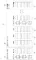
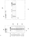
- the distributed control system 1 includes, as main components, a controller, a process IO master device, a process IO module, and a sensor / actuator.
- the distributed control system 1 includes a first A control device 11, a first B control device 12, a second control device 20, a process IO master device 31, process IO modules 100 to 110, and a sensor / actuator 200.
- the first A control device is described as 1 ACU (CONTROL UNIT)
- the 1 B control device is described as 1 BCU
- the second control device is described as 2 CU. The same applies to FIG. 2 and thereafter.
- process IO modules 100 to 110 are appropriately described as the process IO module 100.
- the sensors / actuators 200 to 210 are also described as the sensor / actuator 200 as appropriate, when it is not necessary to distinguish them individually.
- the first A control device 11, the first B control device 12, and the second control device 20 and the process IO master device 31 are connected by a system bus or a network.
- the process IO master device 31 and the process IO modules 100 to 110 are connected by a field bus.
- the process IO modules 100 to 110 and the sensors / actuators 200 to 210 are respectively connected by process signal lines.
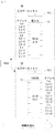
- the process IO master device 31 has an input data memory 40 for storing input data input from each sensor of the process IO modules 100 to 110.
- the process IO master device 31 has an output data memory 50 for storing output data to be output to each actuator of the process IO modules 100 to 110.
- the process IO master device 31 has an output authority table 60 for setting an output authority that determines which control device actually outputs the output data to the actuator.
- the first A control device 11 and the first B control device 12 have a dual redundant configuration in which one is a control system and the other is a standby system.
- the second control device 20 operates in a single-layer configuration, that is, operates alone. This is an example of a system, and the number and combination of control devices are not limited to this.
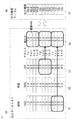
- the input data memory 40 includes real input areas 41, and each area is divided into addresses X ⁇ to X ⁇ + n, addresses X ⁇ to X ⁇ + n, and addresses X ⁇ to X ⁇ + n.
- n 3 in FIG.
- the real input area is described as a real input.
- the sensors of the process IO module 100 address X ⁇ to X ⁇ + 3
- the sensors of the process IO module 101 address X ⁇ to X ⁇ + 3
- the sensors of the process IO module 102 It can be made to correspond to X ⁇ to X ⁇ + 3.
- the output data memory 50 includes a first A controller area 51, a first B controller area 52, a second controller area 53, and an actual output area 54.
- the first A control device area is described as 1 ACU
- the first B control device area is described as 1 BCU
- the second control device area is described as 2 CU
- the actual output area is described as an actual output.
- the first A control device area 51 to the real output area 54 are divided into addresses Y ⁇ to Y ⁇ + n, addresses Y ⁇ to Y ⁇ + n, and addresses Y ⁇ to Y ⁇ + n.
- the output authority table 60 includes an output authority area 61.
- the output authority area 61 is divided into addresses Y ⁇ to Y ⁇ + n, addresses Y ⁇ to Y ⁇ + n, and addresses Y ⁇ to Y ⁇ + n.
- the output authority area is described as an output authority.
- the output authority set in the output authority area 61 corresponds to which control unit (here, the control system side of the first A control unit 11 and the first B control unit 12 or the second control unit 20 for each address of the actual output area 54. Is adopted to determine whether to make the actual output data or hold (HOLD).
- the output authority table 60 authorizes output data determination for each address corresponding to the actuator
- the output authority area 61 is divided into three groups (addresses to facilitate understanding). Y ⁇ to Y ⁇ + n, addresses Y ⁇ to Y ⁇ + n, and addresses Y ⁇ to Y ⁇ + n).
- the real input area 41 of the input data memory 40, and the first A control apparatus area 51 to the real output area 54 of the output data memory 50, and each control apparatus (the first A control apparatus 11, the first B control apparatus 12, the second The relationship between the control device 20) and the process IO modules 100 to 110 will be described.
- the input data input from the sensors of the process IO modules 100 to 110 are stored in the actual input area 41 in the input data memory 40. This input data can be read by each control device (the first A control device 11, the first B control device 12, the second control device 20).
- Actual output data output to the actuators of the process IO modules 100 to 110 are stored in the actual output area 54 in the output data memory 50.
- the actuators of the process IO modules 100 to 110 for example, the actuators of the process IO module 100 are addressed Y ⁇ to Y ⁇ + 3, the actuators of the process IO module 101 are addressed Y ⁇ to Y ⁇ + 3, and the actuators of the process IO module 102 are addressed It can correspond to Y ⁇ to Y ⁇ + 3.
- the function of the output authority table 60 will be described based on FIGS. 3 to 7 in a specific setting example.
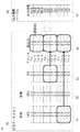
- the normal operation state will be described with reference to FIG.
- the first A control device 11 is a control system
- the first B control device 12 is a standby system. Further, it is assumed that the information that the first A control device 11 is a control system is notified to the process IO master device.
- the authority of addresses Y ⁇ to Y ⁇ + 3 of output authority area 61 is set to the first control device
- the authority of addresses Y ⁇ to Y ⁇ + 3 is set to the second control device
- the authority of addresses Y ⁇ to Y ⁇ + 3 is the first control device. It is set to.
- the setting of the output authority is the first control device
- information on which of the first A control device 11 and the first B control device 12 is the device on the control system side is separately received, and the control system side is Adopt the output data of Therefore, the same operation as the conventional standby redundant configuration is possible.
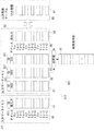
- the output data from the first A controller 11 and the first B controller 12 is 1.0 at the addresses Y ⁇ to Y ⁇ + 3, 2.0 at the addresses Y ⁇ to Y ⁇ + 3, and 5.0 at the addresses Y ⁇ to Y ⁇ + 3.
- the output data from the second control device 20 is 0.0 at the addresses Y ⁇ to Y ⁇ + 3, 3.0 at the addresses Y ⁇ to Y ⁇ + 3, and 4.0 at the addresses Y ⁇ to Y ⁇ + 3.
- data are set as follows in each address of the real output area 54. That is, 1.0 which is the output of the first A control device 11 is adopted for the addresses Y ⁇ to Y ⁇ + 3, 3.0 which is the output of the second control device 20 is adopted for the addresses Y ⁇ to Y ⁇ + 3 and the addresses Y ⁇ to Y ⁇ + 3. , Which is the output of the first A control device 11, is adopted.
- FIG. 4 an example will be described in which data output from the first A control device 11 or the first B control device 12 is used as actual output data, and output data from the second control device 20 is switched to actual output data.
- the authority of the output authority area addresses Y ⁇ to Y ⁇ + 3 of the output authority table 60 is changed to hold (step 1).
- the actual output data corresponding to the addresses Y ⁇ to Y ⁇ + 3 of the actual output area 54 is not updated (* A1).
- step 2 the control logic of the second control device 20 is rewritten and changed to output data (step 2).
- the output authority of the output authority area addresses Y ⁇ to Y ⁇ + 3 of the output authority table 60 is kept on hold, the actual output data corresponding to the addresses Y ⁇ to Y ⁇ + 3 of the real output area 54 is not updated (* A1) It is as it is.
- the output data from the second control device 20 changes from 0.0 to 0.7 at the addresses Y ⁇ to Y ⁇ + 3.
- step 3 the control logics of the first A control device 11 and the first B control device 12 are rewritten (step 3).
- the output authority of the output authority area addresses Y ⁇ to Y ⁇ + 3 of the output authority table 60 is kept hold, the actual output data corresponding to the addresses Y ⁇ to Y ⁇ + 3 of the real output area 54 is not updated (* A1) It is as it is.
- the output authority area addresses Y ⁇ to Y ⁇ + 3 of the output authority table 60 are changed from the hold to the output adoption of the second control unit 20 (step 4).
- the actual output data corresponding to the addresses Y ⁇ to Y ⁇ + 3 of the actual output area 54 2 Output data from the control device 20 is adopted and updated (* A2) to 1.1.
- the distributed control system 1 separates the control device having the control logic and performing the control operation from the process IO master performing the output control, so that output to the actuator is performed without unnecessarily stopping the control operation.
- the controller can be easily changed. Therefore, in this distributed control system 1, the process IO modules are shared between the control devices of the duplex or single configuration, but in the case of each control device, the conventional configuration, that is, the process IO for each distributed control device.
- the same system design as a system equipped with a master device can be performed, and the user's usability does not deteriorate.
- the distributed control system includes a plurality of control devices, an output data memory having an area for storing data shared by the control devices and output from each control device, and an output authority table And a plurality of process IO modules connected to the sensor and the actuator, and the output authority table is an authority to determine which control device output data is adopted for each address corresponding to the actuator
- the present invention relates to a distributed control system that gives Therefore, it is possible to share input signals between the control devices and flexibly cope with the change of the output actuator without changing the hardware on the outside line.
- the output authority table is configured to set the output authority for each address, but in the distributed control system of the second embodiment, the output authority table is configured to set the output authority in block units.
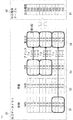
- FIG. 8 is an explanatory diagram of the output authority table.
- the same or corresponding parts as in FIGS. 1 and 2 of the first embodiment are given the same reference numerals.
- the distributed control system 201 is used to distinguish it from the first embodiment.
- FIG. 8A is an explanatory diagram of the output authority table 60 described in FIG. 7 of the first embodiment.
- Output authority is set for each address.
- the output authority of the addresses Y ⁇ to Y ⁇ + 3 of the output authority area 61 is set to the second control device
- the output authority of the addresses Y ⁇ to Y ⁇ + 3 is set to the second control device
- the output authority of the addresses Y ⁇ to Y ⁇ + 3 is It is set to the first control device.
- the output authority of the addresses Y ⁇ to Y ⁇ + 3 can be regarded as one process IO module as a whole (mass) set in the second control device. This is represented by a symbol * B1 in the diagram of FIG. 8 (a).
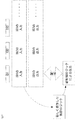
- FIG. 8B is an explanatory diagram of the output authority table 60 according to the second embodiment.
- the authority area 62 has an address part, a size part, and an output authority part.
- FIG. 8A an example corresponding to the output authority table 60 (that is, FIG. 8A) described in FIG. 7 of the first embodiment is described.
- the size of the address Y ⁇ is 4 and the output authority is set to the second control device.
- the size of the address Y ⁇ is 4, and the output right is set to the second control device.
- the size of the address Y ⁇ is 4, and the output right is set to the first control device.
- the output authority table 60 is a block unit in which a plurality of addresses (for example, Y ⁇ to Y ⁇ + 3) are put together.
- the distributed control system according to the second embodiment is configured to set the output authority in block units of the output authority table. Therefore, in the distributed control system according to the second embodiment, as in the first embodiment, the control devices share input signals and can flexibly cope with the change of the output actuator without changing the hardware at the outside line. . Furthermore, the size of the output authority table can be reduced, and hardware resources can be reduced.
- the distributed control system of the third embodiment is configured such that the distributed control system of the first embodiment is provided with an input data changing mechanism for changing input data input from a sensor and acquired by a control device.
- FIGS. 9 and 10 are explanatory diagrams of an input data change mechanism.
- FIGS. 9 and 10 the same or corresponding parts as in FIGS. 1 and 2 of the first embodiment are given the same reference numerals. Note that the distributed control system 301 is used to distinguish it from the first embodiment.
- the input data change mechanism 310 includes an input data memory 40, an input processing table 70, and an input data changer 75.
- the input data memory 40 includes an actual input area 41.
- the actual input area 41 is divided into addresses X ⁇ to X ⁇ + 3, addresses X ⁇ to X ⁇ + 3, and addresses X ⁇ to X ⁇ + 3.
- Data from the sensors of the process IO module 100 are input to the addresses X ⁇ to X ⁇ + 3.
- Data from the sensor of the process IO module 101 is input to the addresses X ⁇ to X ⁇ + 3, and data from the sensor of the process IO module 102 is input to the addresses X ⁇ to X ⁇ + 3.
- the actual input area is described as an actual input.
- the process IO module 100 is described as IO 100, the process IO module 101 as IO 101, and the process IO module 102 as IO 102.
- the data from the sensors of the sensors / actuators 201 to 210 input to the actual input area 41 are read into the first A control device 11, the first B control device 12 and the second control device 20, respectively.
- the input processing table 70 has an address part, a size part, and an input processing part as the input processing area 72.
- a block unit corresponding to the configuration of the real input area 41 of the input data memory 40 is used.
- the size of the address X ⁇ is 4 and the input process is set to be effective.
- the size of the address X ⁇ is 4, the input processing is all valid, the size of the address X ⁇ is 4, and the input processing is set valid.
- FIG. 9 shows a normal state, and the input processing of the input processing table 70 is set to be effective. Since the input processing area 72 of the input processing table 70 is valid, input data from the sensors of the process IO modules 100 to 102 are expanded in the real input area 41 of the input data memory 40.
- the input data changer 75 changes corresponding data in the real input area 41 of the input data memory 40 to an arbitrary value when the input processing of the input processing table 70 is invalid, as described later.
- the input process of the address X ⁇ of the input process table 70 is changed to be invalid (step 1).
- * C1 corresponds to step 1.
- the data of the addresses X ⁇ to X ⁇ + 3 of the real input area 41 of the input data memory 40 becomes invalid (step 2).
- * C2 corresponds to step 2.
- the input data changer 75 changes the input data from the sensor of the process IO module 100 to an arbitrary value (step 3).
- * C3 corresponds to step 3.
- the data of the address X ⁇ is 1.5
- the data of the address X ⁇ + 1 is 2.5
- the data of the address X ⁇ + 2 is 3.0
- the data of the address X ⁇ + 3 is 5.0.
- the values changed by the input data changer 75 are acquired as data input from the sensor of the process IO module 100 to the first A control device 11, the first B control device 12, and the second control device 20. .
- the effectiveness of the input data changing mechanism 310 described in the distributed control system 301 of the third embodiment will be described. It is assumed that input data from the sensors of the process IO module 100 are used in the first A control device 11, the first B control device 12, and the second control device 20. When it is desired to change the input value in a test and confirm the operation, if the control device simulates the input value, the operations do not match between the respective control devices. However, by providing the input data changing mechanism 310 of the distributed control system 301, the same data can be acquired by all the control devices (the first A control device 11, the first B control device 12, and the second control device 20). Therefore, the test using the input data shared between the control devices can be performed more easily and accurately, and the test efficiency can be improved.
- the input data change mechanism 310 is added to the distributed control system 1 of the first embodiment, but even if the input data change mechanism is added to the distributed control system 201 of the second embodiment, the control devices share The efficiency of the test using the input data can be improved.
- the distributed control system according to the first embodiment is provided with an input data changing mechanism for changing input data input from the sensor, and acquired by the control device It is Therefore, in the distributed control system according to the third embodiment, as in the first embodiment, the control devices share input signals and can flexibly cope with the change of the output actuator without changing the hardware at the outside line. . Furthermore, the efficiency of the test using the input data shared between the control devices can be improved.
- the distributed control system of the fourth embodiment is provided with a time-series data management mechanism that assigns identification data of time series to input data and output data and manages the distributed control system of the first embodiment.
- FIG. 11 is an explanatory diagram of a time-series data management mechanism
- FIG. 12 is an explanatory diagram of time-series data
- FIG. 13 and an explanatory diagram of an application example of time-series data.
- the difference from the first embodiment will be mainly described based on FIG. 11 to FIG. 14, the same or corresponding parts as in FIG. 1 and FIG. 2 of the first embodiment are assigned the same reference numerals.
- the distributed control system 401 is used to distinguish it from the first embodiment.
- the time-series data management mechanism 410 includes an input data memory 40, an output data memory 50, an output authority table 60, and a time-series data storage unit 80.
- the input data memory 40 comprises an actual input area 41 and further input time-series data 41I.
- the output data memory 50 includes a first A controller area 51, a first B controller area 52, a second controller area 53, and a real output area 54, and further, from the first A controller area 51 to the second controller area 53.
- the output time-series data 51I to the output time-series data 53I are provided.
- the output authority table 60 includes an output authority area 61.
- the output authority area 61 is divided into addresses Y ⁇ to Y ⁇ + n, addresses Y ⁇ to Y ⁇ + n, and addresses Y ⁇ to Y ⁇ + n.
- the time series data storage unit 80 stores actual input data to which time series data is given, output data of the first A control device 11, output data of the first B control device 12, and output data of the second control device 20.
- the time-series identification data is incremented in the process IO master device 31 for each input process. In the figure, time-series identification data is described as ID.
- FIG. 12 shows data relating to the first A control device 11 to which time-series identification data (1 in this case) is added, and actual input data at a certain point in time and output data of the first A control device 11 are saved as a set.
- FIG. 13 shows data relating to the first A control device 11 to which time-series identification data (2 in this case) is given after a certain time has passed from FIG. 12, and actual input data at this point and the first A control device 11 Output data of is stored as a set.
- the time-series data storage unit 80 includes, for example, actual input data for time-series identification data ID1, ID2, ID3,... And output data of the first A control device 11 as data regarding the first A control device 11.
- the newly produced control logic confirms whether it has the function as designed. Specifically, the actual input data for the time-series identification data ID1 is input to the newly manufactured control logic, and the output of the new control logic is compared with the output data of the first A control device 11.
- the function of the new control logic that is, the control operation can be verified using actual input data for each time-series identification data ID2, ID3... And output data of the first A control device 11.
- the time-series data storage unit 80 does not have to store all the data to which the time-series identification data has been added, and may be used for the necessary control device according to the target requiring verification of the control operation. Data can be stored regularly or randomly.
- the time-series data storage unit 80 is provided in the process IO master device 31. However, in each control device (the first A control device 11, the first B control device 12, and the second control device 20) Alternatively, it can be provided outside the distributed control system 401.
- time-series data management mechanism is added to the distributed control system 1 according to the first embodiment.
- time-series data management is performed for the distributed control system 201 according to the second embodiment or the distributed control system 301 according to the third embodiment.
- a mechanism may be added.
- the distributed control system of the first embodiment is provided with a time-series data management mechanism for adding and managing time-series identification data to input data and output data. It is Therefore, in the distributed control system according to the fourth embodiment, as in the first embodiment, the control devices share input signals and can flexibly cope with the change of the output actuator without changing the hardware on the outside line. . Furthermore, verification of control operation can be enabled.
- Embodiment 5 According to the distributed control system of the fifth embodiment, the distributed control system of the first embodiment detects the difference between the output data output from the control device to the process IO master device and the actual output data output to the actuator. A data difference detection mechanism is provided.
- FIG. 15 is an explanatory diagram of an output data difference detection mechanism.
- the same or corresponding parts as in FIGS. 1 and 2 of the first embodiment are given the same reference numerals.
- it is set as the distributed control system 501.
- the output data difference detection mechanism 510 includes an input data memory 40, an output data memory 50, an output authority table 60, a comparator 90, and a result storage unit 91.
- the input data memory 40 comprises an actual input area 41 and further input time-series data 41I.
- the output data memory 50 includes a first A controller area 51, a first B controller area 52, a second controller area 53, and a real output area 54, and further, from the first A controller area 51 to the second controller area 53.
- the output time-series data 51I to the output time-series data 53I are provided.
- the output authority table 60 includes an output authority area 61.
- the output authority area 61 is divided into addresses Y ⁇ to Y ⁇ + 3, addresses Y ⁇ to Y ⁇ + 3, and addresses Y ⁇ to Y ⁇ + 3.
- the comparator 90 compares the actual output data of the actual output area 54 with the output data of the control device (for example, the first B control device) to be compared.
- the result storage unit 91 stores the results compared by the comparator 90.
- One of the first A control device 11 and the first B control device 12 has a dual redundant configuration in which one is a control system and the other is a standby system.
- the first A control device 11 is a control system
- the first B control device 12 is a standby system. Since the output data of the first B control device 12 which is a standby system is not adopted as actual input data, it is not output to the actuator.
- the output data difference detection mechanism 510 by constantly comparing the actual output data of the actual output area 54 with the output data of the first B control apparatus, an abnormality in the first B control apparatus 12 is detected in advance. can do.
- the control logics of the first A control device 11 and the first B control device 12 are different from the control logic of the control device 2, the difference is shown, so only the address area in which the output authority is in the first control device is compared.
- the control logics of the first A control device 11 and the first B control device 12 and the control device 2 may be the same or partially the same.
- the abnormality of the second control device 20 can be made in advance. Can be detected. Therefore, it is possible to constantly monitor the abnormality of the control device which does not have the output authority (so-called control device in the standby state). Furthermore, the control device in the standby state can be constantly monitored, and when there is an abnormality, the host system can be notified that an abnormality has been detected, and the inspection and replacement can be promoted.
- the result storage unit 91 is provided in the process IO master device 31.
- the result storage unit 91 may be provided outside the distributed control system 501.
- the output data difference detection mechanism is added to the distributed control system 1 of the first embodiment, but the output data difference detection mechanism may be added to the distributed control system of the second embodiment to the fourth embodiment. .
- the distributed control system according to the first embodiment includes the output data output from the control device to the process IO master device and the actual output data output to the actuator.
- An output data difference detection mechanism for detecting the difference between Therefore, in the distributed control system according to the fifth embodiment, as in the first embodiment, the control devices share input signals and can flexibly cope with the change of the output actuator without changing the hardware on the outside line. . Further, it is possible to constantly monitor the abnormality of the control device in the standby state.
- each embodiment can be freely combined, or the embodiment can be appropriately modified or omitted.
- the present invention can be widely applied to a distributed control system because it can flexibly cope with input signal sharing between control devices and change of an actuator to be output without hardware change on the outside line.
Landscapes
- Physics & Mathematics (AREA)
- General Physics & Mathematics (AREA)
- Engineering & Computer Science (AREA)
- Automation & Control Theory (AREA)
- Programmable Controllers (AREA)
Abstract
L'invention porte sur un système de commande distribué (1) qui comprend : une pluralité de dispositifs de commande (11, 12, 20) ; un appareil maître d'entrée/sortie (E/S) de processus (31) pourvu d'une table d'autorisation de sortie (60) et d'une mémoire de données de sortie (50) comportant une zone dans laquelle sont stockées des données partagées entre les dispositifs de commande (11, 12, 20) et délivrées par chacun des dispositifs de commande (11, 12, 20) ; et une pluralité de modules E/S de processus (100 à 110) connectés à l'appareil maître E/S de processus (31) et connectés à des capteurs/actionneurs (200 à 210). La table d'autorisation de sortie (60) fournit une autorisation pour décider de quel dispositif de commande (11, 12, 20) les données de sortie doivent être adoptées pour chaque adresse parmi des adresses correspondant aux actionneurs.
Priority Applications (5)
| Application Number | Priority Date | Filing Date | Title |
|---|---|---|---|
| US16/629,200 US11531315B2 (en) | 2017-10-12 | 2017-10-12 | Distributed control system |
| JP2019547853A JP6921219B2 (ja) | 2017-10-12 | 2017-10-12 | 分散制御システム |
| EP17928636.4A EP3696627B1 (fr) | 2017-10-12 | 2017-10-12 | Système de commande distribué |
| CN201780095489.7A CN111164523B (zh) | 2017-10-12 | 2017-10-12 | 分散控制系统 |
| PCT/JP2017/036946 WO2019073565A1 (fr) | 2017-10-12 | 2017-10-12 | Système de commande distribué |
Applications Claiming Priority (1)
| Application Number | Priority Date | Filing Date | Title |
|---|---|---|---|
| PCT/JP2017/036946 WO2019073565A1 (fr) | 2017-10-12 | 2017-10-12 | Système de commande distribué |
Publications (1)
| Publication Number | Publication Date |
|---|---|
| WO2019073565A1 true WO2019073565A1 (fr) | 2019-04-18 |
Family
ID=66100537
Family Applications (1)
| Application Number | Title | Priority Date | Filing Date |
|---|---|---|---|
| PCT/JP2017/036946 WO2019073565A1 (fr) | 2017-10-12 | 2017-10-12 | Système de commande distribué |
Country Status (5)
| Country | Link |
|---|---|
| US (1) | US11531315B2 (fr) |
| EP (1) | EP3696627B1 (fr) |
| JP (1) | JP6921219B2 (fr) |
| CN (1) | CN111164523B (fr) |
| WO (1) | WO2019073565A1 (fr) |
Cited By (1)
| Publication number | Priority date | Publication date | Assignee | Title |
|---|---|---|---|---|
| CN111176227A (zh) * | 2019-12-06 | 2020-05-19 | 南京国电南自维美德自动化有限公司 | 一种控制任务与输入输出数据同步触发的实现系统及方法 |
Citations (5)
| Publication number | Priority date | Publication date | Assignee | Title |
|---|---|---|---|---|
| JPH05173985A (ja) * | 1991-12-24 | 1993-07-13 | Matsushita Electric Works Ltd | プログラマブルコントローラ |
| JPH06259114A (ja) | 1993-03-02 | 1994-09-16 | Hitachi Ltd | プログラマブルコントローラ |
| JPH06301409A (ja) | 1993-04-19 | 1994-10-28 | Sharp Corp | 多重化プログラムコントローラ |
| JP2003085119A (ja) * | 2001-09-10 | 2003-03-20 | Digital Electronics Corp | 入出力アドレス設定装置、入出力アドレス設定プログラムおよびそれを記録した記録媒体 |
| JP2010250435A (ja) * | 2009-04-13 | 2010-11-04 | Mitsubishi Electric Corp | プラント監視制御システム |
Family Cites Families (13)
| Publication number | Priority date | Publication date | Assignee | Title |
|---|---|---|---|---|
| US6618628B1 (en) * | 2000-10-05 | 2003-09-09 | Karl A. Davlin | Distributed input/output control systems and methods |
| US7079117B2 (en) * | 2003-05-15 | 2006-07-18 | Analog Devices, Inc. | Analog to digital converter controller |
| US20090076628A1 (en) * | 2007-09-18 | 2009-03-19 | David Mark Smith | Methods and apparatus to upgrade and provide control redundancy in process plants |
| KR20110024435A (ko) * | 2009-09-02 | 2011-03-09 | 삼성전자주식회사 | 제어 디바이스, 피제어 디바이스, 제어 시스템, 그리고 제어권한 제공방법 |
| US8615683B2 (en) * | 2011-06-24 | 2013-12-24 | Rockwell Automation Technologies, Inc. | Capturing data during operation of an industrial controller for the debugging of control programs |
| FR2982960B1 (fr) * | 2011-11-22 | 2014-06-27 | Schneider Electric Usa Inc | Adaptation dynamique a des changements dans une topologie de systeme de commande |
| WO2014037970A1 (fr) * | 2012-09-04 | 2014-03-13 | 三菱電機株式会社 | Système de commande d'e/s distribuée, procédé de commande d'e/s distribuée, et station maître et station esclave du système de commande d'e/s distribuée |
| US9384857B2 (en) * | 2014-04-30 | 2016-07-05 | International Business Machines Corporation | Error control using threshold based comparison of error signatures |
| EP3180662B1 (fr) | 2014-09-25 | 2019-11-20 | Siemens Aktiengesellschaft | Appareil de commande de système d'automatisation |
| JP6560489B2 (ja) * | 2014-11-25 | 2019-08-14 | 株式会社日立製作所 | 制御コントローラおよびその制御方法 |
| JP6602684B2 (ja) * | 2016-02-15 | 2019-11-06 | 株式会社東芝 | 制御装置および制御方法 |
| JP6772531B2 (ja) * | 2016-04-28 | 2020-10-21 | オムロン株式会社 | 制御システム、制御方法、制御プログラム、および記録媒体 |
| JP6874438B2 (ja) * | 2017-03-14 | 2021-05-19 | オムロン株式会社 | スレーブ装置、スレーブ装置の制御方法、情報処理プログラム、および記録媒体 |
-
2017
- 2017-10-12 US US16/629,200 patent/US11531315B2/en active Active
- 2017-10-12 CN CN201780095489.7A patent/CN111164523B/zh active Active
- 2017-10-12 JP JP2019547853A patent/JP6921219B2/ja active Active
- 2017-10-12 EP EP17928636.4A patent/EP3696627B1/fr active Active
- 2017-10-12 WO PCT/JP2017/036946 patent/WO2019073565A1/fr unknown
Patent Citations (5)
| Publication number | Priority date | Publication date | Assignee | Title |
|---|---|---|---|---|
| JPH05173985A (ja) * | 1991-12-24 | 1993-07-13 | Matsushita Electric Works Ltd | プログラマブルコントローラ |
| JPH06259114A (ja) | 1993-03-02 | 1994-09-16 | Hitachi Ltd | プログラマブルコントローラ |
| JPH06301409A (ja) | 1993-04-19 | 1994-10-28 | Sharp Corp | 多重化プログラムコントローラ |
| JP2003085119A (ja) * | 2001-09-10 | 2003-03-20 | Digital Electronics Corp | 入出力アドレス設定装置、入出力アドレス設定プログラムおよびそれを記録した記録媒体 |
| JP2010250435A (ja) * | 2009-04-13 | 2010-11-04 | Mitsubishi Electric Corp | プラント監視制御システム |
Cited By (1)
| Publication number | Priority date | Publication date | Assignee | Title |
|---|---|---|---|---|
| CN111176227A (zh) * | 2019-12-06 | 2020-05-19 | 南京国电南自维美德自动化有限公司 | 一种控制任务与输入输出数据同步触发的实现系统及方法 |
Also Published As
| Publication number | Publication date |
|---|---|
| EP3696627A4 (fr) | 2020-09-16 |
| JPWO2019073565A1 (ja) | 2020-04-02 |
| JP6921219B2 (ja) | 2021-08-18 |
| US20210356929A1 (en) | 2021-11-18 |
| CN111164523A (zh) | 2020-05-15 |
| US11531315B2 (en) | 2022-12-20 |
| EP3696627A1 (fr) | 2020-08-19 |
| EP3696627B1 (fr) | 2023-07-12 |
| CN111164523B (zh) | 2023-08-29 |
Similar Documents
| Publication | Publication Date | Title |
|---|---|---|
| US20090193158A1 (en) | Storage system, device controller, and improper cable connection determination method | |
| US20100131801A1 (en) | Electronic system for detecting a fault | |
| CN103975314B (zh) | 横跨多个存储器区的强有序、装置及互斥事务的自动排序 | |
| JP2010262432A (ja) | 安全制御装置 | |
| RU2411570C2 (ru) | Способ и устройство для сравнения данных в вычислительной системе, включающей в себя по меньшей мере два исполнительных блока | |
| US10114356B2 (en) | Method and apparatus for controlling a physical unit in an automation system | |
| JP2010003081A (ja) | 演算処理装置多重化制御システム | |
| JPWO2014125606A1 (ja) | 制御装置 | |
| JP6149161B2 (ja) | チップセレクトを低減させるデバイス、システム、及び方法 | |
| CN104809074A (zh) | 存储器控制设备、信息处理装置和存储器控制方法 | |
| JP6921219B2 (ja) | 分散制御システム | |
| US20170154480A1 (en) | Information processing apparatus and large scale integrated circuit | |
| JP6277971B2 (ja) | 情報処理装置 | |
| US8316168B2 (en) | Method and communications system for the configuration of a communications module containing a logic component | |
| US9317024B2 (en) | Automation system | |
| JP2015045905A (ja) | 情報処理システム、情報処理システムの障害処理方法 | |
| US20140354078A1 (en) | Multi-switching device and multi-switching method thereof | |
| US20090024908A1 (en) | Method for error registration and corresponding register | |
| JP2006236371A (ja) | 制御システム | |
| Ždánsky et al. | Influence of redundancy on safety integrity of SRCS with safety PLC | |
| JP2008234117A (ja) | マルチプロセッサシステムおよびマルチプロセッサシステムにおける復旧方法 | |
| JP2012160149A (ja) | 二重化回路、半導体装置およびテスト方法 | |
| US9858221B2 (en) | Producer/consumer remote synchronization | |
| JP4117685B2 (ja) | フォルトトレラント・コンピュータとそのバス選択制御方法 | |
| US20180032461A1 (en) | Control circuit board, micro-server, control system and control method thereof |
Legal Events
| Date | Code | Title | Description |
|---|---|---|---|
| 121 | Ep: the epo has been informed by wipo that ep was designated in this application |
Ref document number: 17928636 Country of ref document: EP Kind code of ref document: A1 |
|
| ENP | Entry into the national phase |
Ref document number: 2019547853 Country of ref document: JP Kind code of ref document: A |
|
| NENP | Non-entry into the national phase |
Ref country code: DE |
|
| ENP | Entry into the national phase |
Ref document number: 2017928636 Country of ref document: EP Effective date: 20200512 |