WO2019073565A1 - Distributed control system - Google Patents
Distributed control system Download PDFInfo
- Publication number
- WO2019073565A1 WO2019073565A1 PCT/JP2017/036946 JP2017036946W WO2019073565A1 WO 2019073565 A1 WO2019073565 A1 WO 2019073565A1 JP 2017036946 W JP2017036946 W JP 2017036946W WO 2019073565 A1 WO2019073565 A1 WO 2019073565A1
- Authority
- WO
- WIPO (PCT)
- Prior art keywords
- output
- data
- control device
- input
- control system
- Prior art date
Links
Images


Classifications
-
- G—PHYSICS
- G05—CONTROLLING; REGULATING
- G05B—CONTROL OR REGULATING SYSTEMS IN GENERAL; FUNCTIONAL ELEMENTS OF SUCH SYSTEMS; MONITORING OR TESTING ARRANGEMENTS FOR SUCH SYSTEMS OR ELEMENTS
- G05B19/00—Programme-control systems
- G05B19/02—Programme-control systems electric
- G05B19/04—Programme control other than numerical control, i.e. in sequence controllers or logic controllers
- G05B19/05—Programmable logic controllers, e.g. simulating logic interconnections of signals according to ladder diagrams or function charts
- G05B19/054—Input/output
-
- G—PHYSICS
- G05—CONTROLLING; REGULATING
- G05B—CONTROL OR REGULATING SYSTEMS IN GENERAL; FUNCTIONAL ELEMENTS OF SUCH SYSTEMS; MONITORING OR TESTING ARRANGEMENTS FOR SUCH SYSTEMS OR ELEMENTS
- G05B19/00—Programme-control systems
- G05B19/02—Programme-control systems electric
- G05B19/04—Programme control other than numerical control, i.e. in sequence controllers or logic controllers
- G05B19/05—Programmable logic controllers, e.g. simulating logic interconnections of signals according to ladder diagrams or function charts
- G05B19/056—Programming the PLC
-
- G—PHYSICS
- G05—CONTROLLING; REGULATING
- G05B—CONTROL OR REGULATING SYSTEMS IN GENERAL; FUNCTIONAL ELEMENTS OF SUCH SYSTEMS; MONITORING OR TESTING ARRANGEMENTS FOR SUCH SYSTEMS OR ELEMENTS
- G05B19/00—Programme-control systems
- G05B19/02—Programme-control systems electric
- G05B19/04—Programme control other than numerical control, i.e. in sequence controllers or logic controllers
- G05B19/05—Programmable logic controllers, e.g. simulating logic interconnections of signals according to ladder diagrams or function charts
- G05B19/058—Safety, monitoring
-
- G—PHYSICS
- G05—CONTROLLING; REGULATING
- G05B—CONTROL OR REGULATING SYSTEMS IN GENERAL; FUNCTIONAL ELEMENTS OF SUCH SYSTEMS; MONITORING OR TESTING ARRANGEMENTS FOR SUCH SYSTEMS OR ELEMENTS
- G05B2219/00—Program-control systems
- G05B2219/10—Plc systems
- G05B2219/15—Plc structure of the system
- G05B2219/15008—Identify connected I-O and store in address table
-
- G—PHYSICS
- G05—CONTROLLING; REGULATING
- G05B—CONTROL OR REGULATING SYSTEMS IN GENERAL; FUNCTIONAL ELEMENTS OF SUCH SYSTEMS; MONITORING OR TESTING ARRANGEMENTS FOR SUCH SYSTEMS OR ELEMENTS
- G05B2219/00—Program-control systems
- G05B2219/20—Pc systems
- G05B2219/25—Pc structure of the system
- G05B2219/25232—DCS, distributed control system, decentralised control unit
-
- Y—GENERAL TAGGING OF NEW TECHNOLOGICAL DEVELOPMENTS; GENERAL TAGGING OF CROSS-SECTIONAL TECHNOLOGIES SPANNING OVER SEVERAL SECTIONS OF THE IPC; TECHNICAL SUBJECTS COVERED BY FORMER USPC CROSS-REFERENCE ART COLLECTIONS [XRACs] AND DIGESTS
- Y02—TECHNOLOGIES OR APPLICATIONS FOR MITIGATION OR ADAPTATION AGAINST CLIMATE CHANGE
- Y02P—CLIMATE CHANGE MITIGATION TECHNOLOGIES IN THE PRODUCTION OR PROCESSING OF GOODS
- Y02P90/00—Enabling technologies with a potential contribution to greenhouse gas [GHG] emissions mitigation
- Y02P90/02—Total factory control, e.g. smart factories, flexible manufacturing systems [FMS] or integrated manufacturing systems [IMS]
Definitions
- the present invention relates to a distributed control system provided with a plurality of control devices and a process IO master device.
- a controller which is configured of a plurality of CPUs, an arbitration memory, a program memory, and an input / output device, and a plurality of CPUs divide and process one program (for example, Patent Document 1).
- a plurality of CPUs have a function of reading and executing a sequence program in units of one circuit, the bus is managed by the bus contention management circuit, and the execution of the program is managed by the execution management table.
- a controller for parallel processing is disclosed (e.g., Patent Document 2).
- JP 6-259114 A paragraphs [0010]-[0012] and FIGS. 1 and 2)
- the present invention has been made to solve the above problems, and it is an object of the present invention to provide a distributed control system that can flexibly cope with the case of sharing input data between control devices or changing an actuator to be output. I assume.
- a distributed control system is a process IO master apparatus including a plurality of control devices, an output data memory having an area for storing data output from each control device and shared among the control devices, and an output authority table. And a plurality of process IO modules connected to the process IO master device and connected to the sensor and the actuator, and the output authority table adopts output data of which control device for each address corresponding to the area and the actuator It gives the authority to decide
- a distributed control system includes a process IO master device including an output data memory having an area for storing data output from each control device, shared among control devices, and an output authority table, a sensor, and an actuator.
- a process IO master device including an output data memory having an area for storing data output from each control device, shared among control devices, and an output authority table, a sensor, and an actuator.
- a plurality of connected process IO modules are provided, and the output authority table gives the authority to determine which control apparatus output data is to be adopted for each address corresponding to the actuator. For this reason, input signals can be shared between the control devices, and it is possible to flexibly cope with the change of the output actuator without changing the hardware on the outside line.
- the first embodiment is a process IO master device including a plurality of control devices, an output data memory having an area shared by the control devices and storing data output from each control device, and an output authority table, a sensor, and
- the output authority table relates to a distributed control system that includes a plurality of process IO modules connected to the actuator, and the authority to determine which controller output data is to be adopted for each address corresponding to the actuator. .
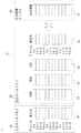
- FIG. 1 showing the configuration of the distributed control system
- FIG. 2 showing the internal configuration of the process IO master device
- FIG. Description will be made based on certain FIGS. 3 to 7.
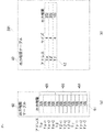
- the distributed control system 1 includes, as main components, a controller, a process IO master device, a process IO module, and a sensor / actuator.
- the distributed control system 1 includes a first A control device 11, a first B control device 12, a second control device 20, a process IO master device 31, process IO modules 100 to 110, and a sensor / actuator 200.
- the first A control device is described as 1 ACU (CONTROL UNIT)
- the 1 B control device is described as 1 BCU
- the second control device is described as 2 CU. The same applies to FIG. 2 and thereafter.
- process IO modules 100 to 110 are appropriately described as the process IO module 100.
- the sensors / actuators 200 to 210 are also described as the sensor / actuator 200 as appropriate, when it is not necessary to distinguish them individually.
- the first A control device 11, the first B control device 12, and the second control device 20 and the process IO master device 31 are connected by a system bus or a network.
- the process IO master device 31 and the process IO modules 100 to 110 are connected by a field bus.
- the process IO modules 100 to 110 and the sensors / actuators 200 to 210 are respectively connected by process signal lines.
- the process IO master device 31 has an input data memory 40 for storing input data input from each sensor of the process IO modules 100 to 110.
- the process IO master device 31 has an output data memory 50 for storing output data to be output to each actuator of the process IO modules 100 to 110.
- the process IO master device 31 has an output authority table 60 for setting an output authority that determines which control device actually outputs the output data to the actuator.
- the first A control device 11 and the first B control device 12 have a dual redundant configuration in which one is a control system and the other is a standby system.
- the second control device 20 operates in a single-layer configuration, that is, operates alone. This is an example of a system, and the number and combination of control devices are not limited to this.
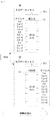
- the input data memory 40 includes real input areas 41, and each area is divided into addresses X ⁇ to X ⁇ + n, addresses X ⁇ to X ⁇ + n, and addresses X ⁇ to X ⁇ + n.
- n 3 in FIG.
- the real input area is described as a real input.
- the sensors of the process IO module 100 address X ⁇ to X ⁇ + 3
- the sensors of the process IO module 101 address X ⁇ to X ⁇ + 3
- the sensors of the process IO module 102 It can be made to correspond to X ⁇ to X ⁇ + 3.
- the output data memory 50 includes a first A controller area 51, a first B controller area 52, a second controller area 53, and an actual output area 54.
- the first A control device area is described as 1 ACU
- the first B control device area is described as 1 BCU
- the second control device area is described as 2 CU
- the actual output area is described as an actual output.
- the first A control device area 51 to the real output area 54 are divided into addresses Y ⁇ to Y ⁇ + n, addresses Y ⁇ to Y ⁇ + n, and addresses Y ⁇ to Y ⁇ + n.
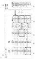
- the output authority table 60 includes an output authority area 61.
- the output authority area 61 is divided into addresses Y ⁇ to Y ⁇ + n, addresses Y ⁇ to Y ⁇ + n, and addresses Y ⁇ to Y ⁇ + n.
- the output authority area is described as an output authority.
- the output authority set in the output authority area 61 corresponds to which control unit (here, the control system side of the first A control unit 11 and the first B control unit 12 or the second control unit 20 for each address of the actual output area 54. Is adopted to determine whether to make the actual output data or hold (HOLD).
- the output authority table 60 authorizes output data determination for each address corresponding to the actuator
- the output authority area 61 is divided into three groups (addresses to facilitate understanding). Y ⁇ to Y ⁇ + n, addresses Y ⁇ to Y ⁇ + n, and addresses Y ⁇ to Y ⁇ + n).
- the real input area 41 of the input data memory 40, and the first A control apparatus area 51 to the real output area 54 of the output data memory 50, and each control apparatus (the first A control apparatus 11, the first B control apparatus 12, the second The relationship between the control device 20) and the process IO modules 100 to 110 will be described.
- the input data input from the sensors of the process IO modules 100 to 110 are stored in the actual input area 41 in the input data memory 40. This input data can be read by each control device (the first A control device 11, the first B control device 12, the second control device 20).
- Actual output data output to the actuators of the process IO modules 100 to 110 are stored in the actual output area 54 in the output data memory 50.
- the actuators of the process IO modules 100 to 110 for example, the actuators of the process IO module 100 are addressed Y ⁇ to Y ⁇ + 3, the actuators of the process IO module 101 are addressed Y ⁇ to Y ⁇ + 3, and the actuators of the process IO module 102 are addressed It can correspond to Y ⁇ to Y ⁇ + 3.
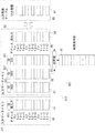
- the function of the output authority table 60 will be described based on FIGS. 3 to 7 in a specific setting example.
- the normal operation state will be described with reference to FIG.
- the first A control device 11 is a control system
- the first B control device 12 is a standby system. Further, it is assumed that the information that the first A control device 11 is a control system is notified to the process IO master device.
- the authority of addresses Y ⁇ to Y ⁇ + 3 of output authority area 61 is set to the first control device
- the authority of addresses Y ⁇ to Y ⁇ + 3 is set to the second control device
- the authority of addresses Y ⁇ to Y ⁇ + 3 is the first control device. It is set to.
- the setting of the output authority is the first control device
- information on which of the first A control device 11 and the first B control device 12 is the device on the control system side is separately received, and the control system side is Adopt the output data of Therefore, the same operation as the conventional standby redundant configuration is possible.
- the output data from the first A controller 11 and the first B controller 12 is 1.0 at the addresses Y ⁇ to Y ⁇ + 3, 2.0 at the addresses Y ⁇ to Y ⁇ + 3, and 5.0 at the addresses Y ⁇ to Y ⁇ + 3.
- the output data from the second control device 20 is 0.0 at the addresses Y ⁇ to Y ⁇ + 3, 3.0 at the addresses Y ⁇ to Y ⁇ + 3, and 4.0 at the addresses Y ⁇ to Y ⁇ + 3.
- data are set as follows in each address of the real output area 54. That is, 1.0 which is the output of the first A control device 11 is adopted for the addresses Y ⁇ to Y ⁇ + 3, 3.0 which is the output of the second control device 20 is adopted for the addresses Y ⁇ to Y ⁇ + 3 and the addresses Y ⁇ to Y ⁇ + 3. , Which is the output of the first A control device 11, is adopted.
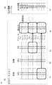
- FIG. 4 an example will be described in which data output from the first A control device 11 or the first B control device 12 is used as actual output data, and output data from the second control device 20 is switched to actual output data.
- the authority of the output authority area addresses Y ⁇ to Y ⁇ + 3 of the output authority table 60 is changed to hold (step 1).
- the actual output data corresponding to the addresses Y ⁇ to Y ⁇ + 3 of the actual output area 54 is not updated (* A1).
- step 2 the control logic of the second control device 20 is rewritten and changed to output data (step 2).
- the output authority of the output authority area addresses Y ⁇ to Y ⁇ + 3 of the output authority table 60 is kept on hold, the actual output data corresponding to the addresses Y ⁇ to Y ⁇ + 3 of the real output area 54 is not updated (* A1) It is as it is.
- the output data from the second control device 20 changes from 0.0 to 0.7 at the addresses Y ⁇ to Y ⁇ + 3.
- step 3 the control logics of the first A control device 11 and the first B control device 12 are rewritten (step 3).
- the output authority of the output authority area addresses Y ⁇ to Y ⁇ + 3 of the output authority table 60 is kept hold, the actual output data corresponding to the addresses Y ⁇ to Y ⁇ + 3 of the real output area 54 is not updated (* A1) It is as it is.
- the output authority area addresses Y ⁇ to Y ⁇ + 3 of the output authority table 60 are changed from the hold to the output adoption of the second control unit 20 (step 4).
- the actual output data corresponding to the addresses Y ⁇ to Y ⁇ + 3 of the actual output area 54 2 Output data from the control device 20 is adopted and updated (* A2) to 1.1.
- the distributed control system 1 separates the control device having the control logic and performing the control operation from the process IO master performing the output control, so that output to the actuator is performed without unnecessarily stopping the control operation.
- the controller can be easily changed. Therefore, in this distributed control system 1, the process IO modules are shared between the control devices of the duplex or single configuration, but in the case of each control device, the conventional configuration, that is, the process IO for each distributed control device.
- the same system design as a system equipped with a master device can be performed, and the user's usability does not deteriorate.
- the distributed control system includes a plurality of control devices, an output data memory having an area for storing data shared by the control devices and output from each control device, and an output authority table And a plurality of process IO modules connected to the sensor and the actuator, and the output authority table is an authority to determine which control device output data is adopted for each address corresponding to the actuator
- the present invention relates to a distributed control system that gives Therefore, it is possible to share input signals between the control devices and flexibly cope with the change of the output actuator without changing the hardware on the outside line.
- the output authority table is configured to set the output authority for each address, but in the distributed control system of the second embodiment, the output authority table is configured to set the output authority in block units.
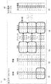
- FIG. 8 is an explanatory diagram of the output authority table.
- the same or corresponding parts as in FIGS. 1 and 2 of the first embodiment are given the same reference numerals.
- the distributed control system 201 is used to distinguish it from the first embodiment.
- FIG. 8A is an explanatory diagram of the output authority table 60 described in FIG. 7 of the first embodiment.
- Output authority is set for each address.
- the output authority of the addresses Y ⁇ to Y ⁇ + 3 of the output authority area 61 is set to the second control device
- the output authority of the addresses Y ⁇ to Y ⁇ + 3 is set to the second control device
- the output authority of the addresses Y ⁇ to Y ⁇ + 3 is It is set to the first control device.
- the output authority of the addresses Y ⁇ to Y ⁇ + 3 can be regarded as one process IO module as a whole (mass) set in the second control device. This is represented by a symbol * B1 in the diagram of FIG. 8 (a).
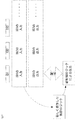
- FIG. 8B is an explanatory diagram of the output authority table 60 according to the second embodiment.
- the authority area 62 has an address part, a size part, and an output authority part.
- FIG. 8A an example corresponding to the output authority table 60 (that is, FIG. 8A) described in FIG. 7 of the first embodiment is described.
- the size of the address Y ⁇ is 4 and the output authority is set to the second control device.
- the size of the address Y ⁇ is 4, and the output right is set to the second control device.
- the size of the address Y ⁇ is 4, and the output right is set to the first control device.
- the output authority table 60 is a block unit in which a plurality of addresses (for example, Y ⁇ to Y ⁇ + 3) are put together.
- the distributed control system according to the second embodiment is configured to set the output authority in block units of the output authority table. Therefore, in the distributed control system according to the second embodiment, as in the first embodiment, the control devices share input signals and can flexibly cope with the change of the output actuator without changing the hardware at the outside line. . Furthermore, the size of the output authority table can be reduced, and hardware resources can be reduced.
- the distributed control system of the third embodiment is configured such that the distributed control system of the first embodiment is provided with an input data changing mechanism for changing input data input from a sensor and acquired by a control device.
- FIGS. 9 and 10 are explanatory diagrams of an input data change mechanism.
- FIGS. 9 and 10 the same or corresponding parts as in FIGS. 1 and 2 of the first embodiment are given the same reference numerals. Note that the distributed control system 301 is used to distinguish it from the first embodiment.
- the input data change mechanism 310 includes an input data memory 40, an input processing table 70, and an input data changer 75.
- the input data memory 40 includes an actual input area 41.
- the actual input area 41 is divided into addresses X ⁇ to X ⁇ + 3, addresses X ⁇ to X ⁇ + 3, and addresses X ⁇ to X ⁇ + 3.
- Data from the sensors of the process IO module 100 are input to the addresses X ⁇ to X ⁇ + 3.
- Data from the sensor of the process IO module 101 is input to the addresses X ⁇ to X ⁇ + 3, and data from the sensor of the process IO module 102 is input to the addresses X ⁇ to X ⁇ + 3.
- the actual input area is described as an actual input.
- the process IO module 100 is described as IO 100, the process IO module 101 as IO 101, and the process IO module 102 as IO 102.
- the data from the sensors of the sensors / actuators 201 to 210 input to the actual input area 41 are read into the first A control device 11, the first B control device 12 and the second control device 20, respectively.
- the input processing table 70 has an address part, a size part, and an input processing part as the input processing area 72.
- a block unit corresponding to the configuration of the real input area 41 of the input data memory 40 is used.
- the size of the address X ⁇ is 4 and the input process is set to be effective.
- the size of the address X ⁇ is 4, the input processing is all valid, the size of the address X ⁇ is 4, and the input processing is set valid.
- FIG. 9 shows a normal state, and the input processing of the input processing table 70 is set to be effective. Since the input processing area 72 of the input processing table 70 is valid, input data from the sensors of the process IO modules 100 to 102 are expanded in the real input area 41 of the input data memory 40.
- the input data changer 75 changes corresponding data in the real input area 41 of the input data memory 40 to an arbitrary value when the input processing of the input processing table 70 is invalid, as described later.
- the input process of the address X ⁇ of the input process table 70 is changed to be invalid (step 1).
- * C1 corresponds to step 1.
- the data of the addresses X ⁇ to X ⁇ + 3 of the real input area 41 of the input data memory 40 becomes invalid (step 2).
- * C2 corresponds to step 2.
- the input data changer 75 changes the input data from the sensor of the process IO module 100 to an arbitrary value (step 3).
- * C3 corresponds to step 3.
- the data of the address X ⁇ is 1.5
- the data of the address X ⁇ + 1 is 2.5
- the data of the address X ⁇ + 2 is 3.0
- the data of the address X ⁇ + 3 is 5.0.
- the values changed by the input data changer 75 are acquired as data input from the sensor of the process IO module 100 to the first A control device 11, the first B control device 12, and the second control device 20. .
- the effectiveness of the input data changing mechanism 310 described in the distributed control system 301 of the third embodiment will be described. It is assumed that input data from the sensors of the process IO module 100 are used in the first A control device 11, the first B control device 12, and the second control device 20. When it is desired to change the input value in a test and confirm the operation, if the control device simulates the input value, the operations do not match between the respective control devices. However, by providing the input data changing mechanism 310 of the distributed control system 301, the same data can be acquired by all the control devices (the first A control device 11, the first B control device 12, and the second control device 20). Therefore, the test using the input data shared between the control devices can be performed more easily and accurately, and the test efficiency can be improved.
- the input data change mechanism 310 is added to the distributed control system 1 of the first embodiment, but even if the input data change mechanism is added to the distributed control system 201 of the second embodiment, the control devices share The efficiency of the test using the input data can be improved.
- the distributed control system according to the first embodiment is provided with an input data changing mechanism for changing input data input from the sensor, and acquired by the control device It is Therefore, in the distributed control system according to the third embodiment, as in the first embodiment, the control devices share input signals and can flexibly cope with the change of the output actuator without changing the hardware at the outside line. . Furthermore, the efficiency of the test using the input data shared between the control devices can be improved.
- the distributed control system of the fourth embodiment is provided with a time-series data management mechanism that assigns identification data of time series to input data and output data and manages the distributed control system of the first embodiment.
- FIG. 11 is an explanatory diagram of a time-series data management mechanism
- FIG. 12 is an explanatory diagram of time-series data
- FIG. 13 and an explanatory diagram of an application example of time-series data.
- the difference from the first embodiment will be mainly described based on FIG. 11 to FIG. 14, the same or corresponding parts as in FIG. 1 and FIG. 2 of the first embodiment are assigned the same reference numerals.
- the distributed control system 401 is used to distinguish it from the first embodiment.
- the time-series data management mechanism 410 includes an input data memory 40, an output data memory 50, an output authority table 60, and a time-series data storage unit 80.
- the input data memory 40 comprises an actual input area 41 and further input time-series data 41I.
- the output data memory 50 includes a first A controller area 51, a first B controller area 52, a second controller area 53, and a real output area 54, and further, from the first A controller area 51 to the second controller area 53.
- the output time-series data 51I to the output time-series data 53I are provided.
- the output authority table 60 includes an output authority area 61.
- the output authority area 61 is divided into addresses Y ⁇ to Y ⁇ + n, addresses Y ⁇ to Y ⁇ + n, and addresses Y ⁇ to Y ⁇ + n.
- the time series data storage unit 80 stores actual input data to which time series data is given, output data of the first A control device 11, output data of the first B control device 12, and output data of the second control device 20.
- the time-series identification data is incremented in the process IO master device 31 for each input process. In the figure, time-series identification data is described as ID.
- FIG. 12 shows data relating to the first A control device 11 to which time-series identification data (1 in this case) is added, and actual input data at a certain point in time and output data of the first A control device 11 are saved as a set.
- FIG. 13 shows data relating to the first A control device 11 to which time-series identification data (2 in this case) is given after a certain time has passed from FIG. 12, and actual input data at this point and the first A control device 11 Output data of is stored as a set.
- the time-series data storage unit 80 includes, for example, actual input data for time-series identification data ID1, ID2, ID3,... And output data of the first A control device 11 as data regarding the first A control device 11.
- the newly produced control logic confirms whether it has the function as designed. Specifically, the actual input data for the time-series identification data ID1 is input to the newly manufactured control logic, and the output of the new control logic is compared with the output data of the first A control device 11.
- the function of the new control logic that is, the control operation can be verified using actual input data for each time-series identification data ID2, ID3... And output data of the first A control device 11.
- the time-series data storage unit 80 does not have to store all the data to which the time-series identification data has been added, and may be used for the necessary control device according to the target requiring verification of the control operation. Data can be stored regularly or randomly.
- the time-series data storage unit 80 is provided in the process IO master device 31. However, in each control device (the first A control device 11, the first B control device 12, and the second control device 20) Alternatively, it can be provided outside the distributed control system 401.
- time-series data management mechanism is added to the distributed control system 1 according to the first embodiment.
- time-series data management is performed for the distributed control system 201 according to the second embodiment or the distributed control system 301 according to the third embodiment.
- a mechanism may be added.
- the distributed control system of the first embodiment is provided with a time-series data management mechanism for adding and managing time-series identification data to input data and output data. It is Therefore, in the distributed control system according to the fourth embodiment, as in the first embodiment, the control devices share input signals and can flexibly cope with the change of the output actuator without changing the hardware on the outside line. . Furthermore, verification of control operation can be enabled.
- Embodiment 5 According to the distributed control system of the fifth embodiment, the distributed control system of the first embodiment detects the difference between the output data output from the control device to the process IO master device and the actual output data output to the actuator. A data difference detection mechanism is provided.
- FIG. 15 is an explanatory diagram of an output data difference detection mechanism.
- the same or corresponding parts as in FIGS. 1 and 2 of the first embodiment are given the same reference numerals.
- it is set as the distributed control system 501.
- the output data difference detection mechanism 510 includes an input data memory 40, an output data memory 50, an output authority table 60, a comparator 90, and a result storage unit 91.
- the input data memory 40 comprises an actual input area 41 and further input time-series data 41I.
- the output data memory 50 includes a first A controller area 51, a first B controller area 52, a second controller area 53, and a real output area 54, and further, from the first A controller area 51 to the second controller area 53.
- the output time-series data 51I to the output time-series data 53I are provided.
- the output authority table 60 includes an output authority area 61.
- the output authority area 61 is divided into addresses Y ⁇ to Y ⁇ + 3, addresses Y ⁇ to Y ⁇ + 3, and addresses Y ⁇ to Y ⁇ + 3.
- the comparator 90 compares the actual output data of the actual output area 54 with the output data of the control device (for example, the first B control device) to be compared.
- the result storage unit 91 stores the results compared by the comparator 90.
- One of the first A control device 11 and the first B control device 12 has a dual redundant configuration in which one is a control system and the other is a standby system.
- the first A control device 11 is a control system
- the first B control device 12 is a standby system. Since the output data of the first B control device 12 which is a standby system is not adopted as actual input data, it is not output to the actuator.
- the output data difference detection mechanism 510 by constantly comparing the actual output data of the actual output area 54 with the output data of the first B control apparatus, an abnormality in the first B control apparatus 12 is detected in advance. can do.
- the control logics of the first A control device 11 and the first B control device 12 are different from the control logic of the control device 2, the difference is shown, so only the address area in which the output authority is in the first control device is compared.
- the control logics of the first A control device 11 and the first B control device 12 and the control device 2 may be the same or partially the same.
- the abnormality of the second control device 20 can be made in advance. Can be detected. Therefore, it is possible to constantly monitor the abnormality of the control device which does not have the output authority (so-called control device in the standby state). Furthermore, the control device in the standby state can be constantly monitored, and when there is an abnormality, the host system can be notified that an abnormality has been detected, and the inspection and replacement can be promoted.
- the result storage unit 91 is provided in the process IO master device 31.
- the result storage unit 91 may be provided outside the distributed control system 501.
- the output data difference detection mechanism is added to the distributed control system 1 of the first embodiment, but the output data difference detection mechanism may be added to the distributed control system of the second embodiment to the fourth embodiment. .
- the distributed control system according to the first embodiment includes the output data output from the control device to the process IO master device and the actual output data output to the actuator.
- An output data difference detection mechanism for detecting the difference between Therefore, in the distributed control system according to the fifth embodiment, as in the first embodiment, the control devices share input signals and can flexibly cope with the change of the output actuator without changing the hardware on the outside line. . Further, it is possible to constantly monitor the abnormality of the control device in the standby state.
- each embodiment can be freely combined, or the embodiment can be appropriately modified or omitted.
- the present invention can be widely applied to a distributed control system because it can flexibly cope with input signal sharing between control devices and change of an actuator to be output without hardware change on the outside line.
Abstract
A distributed control system (1) is provided with: a plurality of control devices (11, 12, 20); a process IO master apparatus (31) provided with an output authorization table (60) and an output data memory (50) having an area in which data shared among the control devices (11, 12, 20) and output from each of the control devices (11, 12, 20) is stored; and a plurality of process IO modules (100 to 110) connected with the process IO master apparatus (31) and connected with sensors/actuators (200 to 210). The output authorization table (60) provides an authorization to decide output data of which control device (11, 12, 20) is to be adopted for each of addresses corresponding to the actuators.
Description
この発明は、複数の制御装置、およびプロセスIOマスタ機器を備えた分散制御システムに関するものである。
The present invention relates to a distributed control system provided with a plurality of control devices and a process IO master device.
プラント制御を行う分散制御システムにおいて、処理速度の高速化、信頼性の向上、およびシステム構成の柔軟性向上が要求されている。
In a distributed control system that performs plant control, it is required to increase processing speed, improve reliability, and improve system configuration flexibility.
これに対応するために、複数のCPUと、調停メモリと、プログラムメモリと、入出力装置とで構成され、1つのプログラムを複数のCPUが分割して処理するコントローラが開示されている(例えば、特許文献1)。
また、複数のCPUにシーケンスプログラムを1回路単位に読み出し実行する機能を持たせ、バスをバス競合管理回路で管理し、プログラムの実行を実行管理テーブルで管理することで、複数のCPUでシーケンスプログラムを並列処理するコントローラが開示されている(例えば、特許文献2)。 In order to cope with this, there is disclosed a controller which is configured of a plurality of CPUs, an arbitration memory, a program memory, and an input / output device, and a plurality of CPUs divide and process one program (for example, Patent Document 1).
In addition, a plurality of CPUs have a function of reading and executing a sequence program in units of one circuit, the bus is managed by the bus contention management circuit, and the execution of the program is managed by the execution management table. A controller for parallel processing is disclosed (e.g., Patent Document 2).
しかし、特許文献1、2開示発明では、コントローラとそれに接続されるプロセスIOマスタ機器と入出力対象機器(センサ/アクチュエータ)の組合せを柔軟に変更する方法は開示されていない。このため、制御装置間で入力データを共有する場合や出力するアクチュエータを変更する場合、外線でのハードウエア変更が必要となり、柔軟に対応できないという問題があった。
However, in the patent documents 1 and 2 disclosed inventions, the method of flexibly changing the combination of the controller, the process IO master device and the input / output target device (sensor / actuator) connected thereto is not disclosed. For this reason, when sharing input data between control devices or changing an output actuator, it is necessary to change the hardware on the outside line, and there is a problem that it is not possible to cope flexibly.
この発明は、上記の問題を解決するためになされたものであり、制御装置間で入力データを共有する場合や出力するアクチュエータを変更する場合に柔軟に対応できる分散制御システムを提供することを目的とする。
The present invention has been made to solve the above problems, and it is an object of the present invention to provide a distributed control system that can flexibly cope with the case of sharing input data between control devices or changing an actuator to be output. I assume.
この発明に係る分散制御システムは、複数の制御装置と、制御装置間で共有され、各制御装置から出力されるデータを保存する領域を有する出力データメモリと出力権限テーブルとを備えるプロセスIOマスタ機器と、プロセスIOマスタ機器に接続され、かつセンサおよびアクチュエータに接続された複数のプロセスIOモジュールとを備え、出力権限テーブルは、領域およびアクチュエータに対応するアドレス毎にどの制御装置の出力データを採用するかを決定する権限を付与するものである。
A distributed control system according to the present invention is a process IO master apparatus including a plurality of control devices, an output data memory having an area for storing data output from each control device and shared among the control devices, and an output authority table. And a plurality of process IO modules connected to the process IO master device and connected to the sensor and the actuator, and the output authority table adopts output data of which control device for each address corresponding to the area and the actuator It gives the authority to decide
この発明に係る分散制御システムは、制御装置間で共有され、各制御装置から出力されるデータを保存する領域を有する出力データメモリと出力権限テーブルとを備えるプロセスIOマスタ機器と、センサおよびアクチュエータに接続された複数のプロセスIOモジュールとを備え、出力権限テーブルは、アクチュエータに対応するアドレス毎にどの制御装置の出力データを採用するかを決定する権限を付与するものである。このため、制御装置間で入力信号を共有し、出力するアクチュエータの変更に対して外線でのハードウエア変更なしで柔軟に対応できる。
A distributed control system according to the present invention includes a process IO master device including an output data memory having an area for storing data output from each control device, shared among control devices, and an output authority table, a sensor, and an actuator. A plurality of connected process IO modules are provided, and the output authority table gives the authority to determine which control apparatus output data is to be adopted for each address corresponding to the actuator. For this reason, input signals can be shared between the control devices, and it is possible to flexibly cope with the change of the output actuator without changing the hardware on the outside line.
実施の形態1.
実施の形態1は、複数の制御装置と、制御装置間で共有され各制御装置から出力されるデータを保存する領域を有する出力データメモリと出力権限テーブルとを備えるプロセスIOマスタ機器と、センサおよびアクチュエータに接続された複数のプロセスIOモジュールとを備え、出力権限テーブルは、アクチュエータに対応するアドレス毎にどの制御装置の出力データを採用するかを決定する権限を付与する分散制御システムに関するものである。Embodiment 1
The first embodiment is a process IO master device including a plurality of control devices, an output data memory having an area shared by the control devices and storing data output from each control device, and an output authority table, a sensor, and The output authority table relates to a distributed control system that includes a plurality of process IO modules connected to the actuator, and the authority to determine which controller output data is to be adopted for each address corresponding to the actuator. .
実施の形態1は、複数の制御装置と、制御装置間で共有され各制御装置から出力されるデータを保存する領域を有する出力データメモリと出力権限テーブルとを備えるプロセスIOマスタ機器と、センサおよびアクチュエータに接続された複数のプロセスIOモジュールとを備え、出力権限テーブルは、アクチュエータに対応するアドレス毎にどの制御装置の出力データを採用するかを決定する権限を付与する分散制御システムに関するものである。
The first embodiment is a process IO master device including a plurality of control devices, an output data memory having an area shared by the control devices and storing data output from each control device, and an output authority table, a sensor, and The output authority table relates to a distributed control system that includes a plurality of process IO modules connected to the actuator, and the authority to determine which controller output data is to be adopted for each address corresponding to the actuator. .
以下、実施の形態1に係る分散制御システムの構成および動作について、分散制御システムの構成図である図1、プロセスIOマスタ機器の内部構成図である図2、および出力権限テーブルの機能説明図である図3-図7に基づいて説明する。
Hereinafter, the configuration and operation of the distributed control system according to the first embodiment will be described with FIG. 1 showing the configuration of the distributed control system, FIG. 2 showing the internal configuration of the process IO master device, and FIG. Description will be made based on certain FIGS. 3 to 7.
まず、実施の形態1の分散制御システムの全体構成を図1に基づいて説明する。
分散制御システム1は、主要構成要素として、制御装置、プロセスIOマスタ機器、プロセスIOモジュール、およびセンサ/アクチュエータを備える。
具体的には、図1において、分散制御システム1は、第1A制御装置11、第1B制御装置12、第2制御装置20、プロセスIOマスタ機器31、プロセスIOモジュール100~110およびセンサ/アクチュエータ200~210から構成される。
なお、図1において、第1A制御装置は1ACU(CONTROL UNIT)、第1B制御装置は1BCU、第2制御装置は2CUと記載している。図2以降も、同様である。
また、プロセスIOモジュール100~110を個別に区別する必要がない場合は、適宜プロセスIOモジュール100と記載する。センサ/アクチュエータ200~210についても、個別に区別する必要がない場合は、適宜センサ/アクチュエータ200と記載する。 First, the overall configuration of the distributed control system according to the first embodiment will be described based on FIG.
Thedistributed control system 1 includes, as main components, a controller, a process IO master device, a process IO module, and a sensor / actuator.
Specifically, in FIG. 1, thedistributed control system 1 includes a first A control device 11, a first B control device 12, a second control device 20, a process IO master device 31, process IO modules 100 to 110, and a sensor / actuator 200. To 210.
In FIG. 1, the first A control device is described as 1 ACU (CONTROL UNIT), the 1 B control device is described as 1 BCU, and the second control device is described as 2 CU. The same applies to FIG. 2 and thereafter.
Further, when it is not necessary to distinguish theprocess IO modules 100 to 110 individually, the process IO modules 100 to 110 are appropriately described as the process IO module 100. The sensors / actuators 200 to 210 are also described as the sensor / actuator 200 as appropriate, when it is not necessary to distinguish them individually.
分散制御システム1は、主要構成要素として、制御装置、プロセスIOマスタ機器、プロセスIOモジュール、およびセンサ/アクチュエータを備える。
具体的には、図1において、分散制御システム1は、第1A制御装置11、第1B制御装置12、第2制御装置20、プロセスIOマスタ機器31、プロセスIOモジュール100~110およびセンサ/アクチュエータ200~210から構成される。
なお、図1において、第1A制御装置は1ACU(CONTROL UNIT)、第1B制御装置は1BCU、第2制御装置は2CUと記載している。図2以降も、同様である。
また、プロセスIOモジュール100~110を個別に区別する必要がない場合は、適宜プロセスIOモジュール100と記載する。センサ/アクチュエータ200~210についても、個別に区別する必要がない場合は、適宜センサ/アクチュエータ200と記載する。 First, the overall configuration of the distributed control system according to the first embodiment will be described based on FIG.
The
Specifically, in FIG. 1, the
In FIG. 1, the first A control device is described as 1 ACU (CONTROL UNIT), the 1 B control device is described as 1 BCU, and the second control device is described as 2 CU. The same applies to FIG. 2 and thereafter.
Further, when it is not necessary to distinguish the
第1A制御装置11、第1B制御装置12、および第2制御装置20とプロセスIOマスタ機器31とは、システムバスもしくはネットワークで接続されている。
プロセスIOマスタ機器31とプロセスIOモジュール100~110とは、フィールドバスで接続されている。プロセスIOモジュール100~110とセンサ/アクチュエータ200~210とは、それぞれプロセス信号線で接続されている。 The first Acontrol device 11, the first B control device 12, and the second control device 20 and the process IO master device 31 are connected by a system bus or a network.
The processIO master device 31 and the process IO modules 100 to 110 are connected by a field bus. The process IO modules 100 to 110 and the sensors / actuators 200 to 210 are respectively connected by process signal lines.
プロセスIOマスタ機器31とプロセスIOモジュール100~110とは、フィールドバスで接続されている。プロセスIOモジュール100~110とセンサ/アクチュエータ200~210とは、それぞれプロセス信号線で接続されている。 The first A
The process
プロセスIOマスタ機器31は、プロセスIOモジュール100~110の各センサから入力される入力データを格納する入力データメモリ40を有する。
プロセスIOマスタ機器31は、プロセスIOモジュール100~110の各アクチュエータへ出力する出力データを格納する出力データメモリ50を有する。
さらに、プロセスIOマスタ機器31は、どの制御装置からの出力データを実際アクチュエータに出力するかを決定する出力権限を設定する出力権限テーブル60を有する。 The processIO master device 31 has an input data memory 40 for storing input data input from each sensor of the process IO modules 100 to 110.
The processIO master device 31 has an output data memory 50 for storing output data to be output to each actuator of the process IO modules 100 to 110.
Furthermore, the processIO master device 31 has an output authority table 60 for setting an output authority that determines which control device actually outputs the output data to the actuator.
プロセスIOマスタ機器31は、プロセスIOモジュール100~110の各アクチュエータへ出力する出力データを格納する出力データメモリ50を有する。
さらに、プロセスIOマスタ機器31は、どの制御装置からの出力データを実際アクチュエータに出力するかを決定する出力権限を設定する出力権限テーブル60を有する。 The process
The process
Furthermore, the process
図1において、第1A制御装置11、第1B制御装置12は、いずれか一方が制御系、もう一方は待機系という二重化冗長構成をとっている。一方、第2制御装置20は一重化構成、すなわち単体動作している。
これは、システム例であり、制御装置の台数、組合せはこれに限るものではない。 In FIG. 1, the firstA control device 11 and the first B control device 12 have a dual redundant configuration in which one is a control system and the other is a standby system. On the other hand, the second control device 20 operates in a single-layer configuration, that is, operates alone.
This is an example of a system, and the number and combination of control devices are not limited to this.
これは、システム例であり、制御装置の台数、組合せはこれに限るものではない。 In FIG. 1, the first
This is an example of a system, and the number and combination of control devices are not limited to this.
次に図2に基づいて、プロセスIOマスタ機器31の内部構成、具体的には入力データメモリ40、出力データメモリ50、および出力権限テーブル60の構成について説明する。
図2において、入力データメモリ40は、実入力領域41を備え、各領域はアドレスXα~Xα+n、アドレスXβ~Xβ+n、およびアドレスXγ~Xγ+nに区分されている。
なお、nはシステムによって異なり任意であるが、図2ではn=3としている。
また、図2では、実入力領域を実入力と記載している。
プロセスIOモジュール100~110のセンサとの対応としては、例えば、プロセスIOモジュール100のセンサをアドレスXα~Xα+3、プロセスIOモジュール101のセンサをアドレスXβ~Xβ+3、また、プロセスIOモジュール102のセンサをアドレスXγ~Xγ+3に対応させることができる。 Next, the internal configuration of the processIO master device 31, specifically, the configuration of the input data memory 40, the output data memory 50, and the output authority table 60 will be described based on FIG.
In FIG. 2, theinput data memory 40 includes real input areas 41, and each area is divided into addresses Xα to Xα + n, addresses Xβ to Xβ + n, and addresses Xγ to Xγ + n.
In addition, although n changes with systems and is arbitrary, it is referred to as n = 3 in FIG.
Further, in FIG. 2, the real input area is described as a real input.
As correspondence with the sensors of theprocess IO modules 100 to 110, for example, the sensors of the process IO module 100 address Xα to Xα + 3, the sensors of the process IO module 101 address Xβ to Xβ + 3, and the sensors of the process IO module 102 It can be made to correspond to Xγ to Xγ + 3.
図2において、入力データメモリ40は、実入力領域41を備え、各領域はアドレスXα~Xα+n、アドレスXβ~Xβ+n、およびアドレスXγ~Xγ+nに区分されている。
なお、nはシステムによって異なり任意であるが、図2ではn=3としている。
また、図2では、実入力領域を実入力と記載している。
プロセスIOモジュール100~110のセンサとの対応としては、例えば、プロセスIOモジュール100のセンサをアドレスXα~Xα+3、プロセスIOモジュール101のセンサをアドレスXβ~Xβ+3、また、プロセスIOモジュール102のセンサをアドレスXγ~Xγ+3に対応させることができる。 Next, the internal configuration of the process
In FIG. 2, the
In addition, although n changes with systems and is arbitrary, it is referred to as n = 3 in FIG.
Further, in FIG. 2, the real input area is described as a real input.
As correspondence with the sensors of the
図2において、出力データメモリ50は、第1A制御装置領域51、第1B制御装置領域52、第2制御装置領域53、および実出力領域54を備える。
図2では、第1A制御装置領域を1ACUと、第1B制御装置領域を1BCUと、第2制御装置領域を2CUと、および実出力領域を実出力と記載している。
第1A制御装置領域51~実出力領域54は、アドレスYα~Yα+n、アドレスYβ~Yβ+n、およびアドレスYγ~Yγ+nに区分されている。
nはシステムによって異なり任意であるが、図2ではn=3としている。 In FIG. 2, theoutput data memory 50 includes a first A controller area 51, a first B controller area 52, a second controller area 53, and an actual output area 54.
In FIG. 2, the first A control device area is described as 1 ACU, the first B control device area is described as 1 BCU, the second control device area is described as 2 CU, and the actual output area is described as an actual output.
The first Acontrol device area 51 to the real output area 54 are divided into addresses Yα to Yα + n, addresses Yβ to Yβ + n, and addresses Yγ to Yγ + n.
Although n differs depending on the system and is arbitrary, n = 3 in FIG.
図2では、第1A制御装置領域を1ACUと、第1B制御装置領域を1BCUと、第2制御装置領域を2CUと、および実出力領域を実出力と記載している。
第1A制御装置領域51~実出力領域54は、アドレスYα~Yα+n、アドレスYβ~Yβ+n、およびアドレスYγ~Yγ+nに区分されている。
nはシステムによって異なり任意であるが、図2ではn=3としている。 In FIG. 2, the
In FIG. 2, the first A control device area is described as 1 ACU, the first B control device area is described as 1 BCU, the second control device area is described as 2 CU, and the actual output area is described as an actual output.
The first A
Although n differs depending on the system and is arbitrary, n = 3 in FIG.
出力権限テーブル60は、出力権限領域61を備え、この出力権限領域61は、アドレスYα~Yα+n、アドレスYβ~Yβ+n、およびアドレスYγ~Yγ+nに区分されている。
図2では、出力権限領域を出力権限と記載している。
この出力権限領域61に設定された出力権限は、実出力領域54のアドレス毎にどの制御装置(ここでは、第1A制御装置11および第1B制御装置12の制御系側、あるいは第2制御装置20)の出力データを採用して、実出力データとするか、もしくはホールド(HOLD)するかを決めるものである。
出力権限テーブル60は、アクチュエータに対応するアドレス毎の出力データ決定の権限を付与するものであるが、本実施の形態1では、理解を容易にするため、出力権限領域61を3つのグループ(アドレスYα~Yα+n、アドレスYβ~Yβ+n、およびアドレスYγ~Yγ+n)にまとめている。
この実出力データを決める仕組みを備えることで、実際にプロセスIOモジュール100のアクチュエータに出力する制御装置を容易に切り替えることが可能になる。 The output authority table 60 includes anoutput authority area 61. The output authority area 61 is divided into addresses Yα to Yα + n, addresses Yβ to Yβ + n, and addresses Yγ to Yγ + n.
In FIG. 2, the output authority area is described as an output authority.
The output authority set in theoutput authority area 61 corresponds to which control unit (here, the control system side of the first A control unit 11 and the first B control unit 12 or the second control unit 20 for each address of the actual output area 54. Is adopted to determine whether to make the actual output data or hold (HOLD).
Although the output authority table 60 authorizes output data determination for each address corresponding to the actuator, in the first embodiment, theoutput authority area 61 is divided into three groups (addresses to facilitate understanding). Yα to Yα + n, addresses Yβ to Yβ + n, and addresses Yγ to Yγ + n).
By providing the mechanism for determining the actual output data, it is possible to easily switch the control device that is actually output to the actuator of theprocess IO module 100.
図2では、出力権限領域を出力権限と記載している。
この出力権限領域61に設定された出力権限は、実出力領域54のアドレス毎にどの制御装置(ここでは、第1A制御装置11および第1B制御装置12の制御系側、あるいは第2制御装置20)の出力データを採用して、実出力データとするか、もしくはホールド(HOLD)するかを決めるものである。
出力権限テーブル60は、アクチュエータに対応するアドレス毎の出力データ決定の権限を付与するものであるが、本実施の形態1では、理解を容易にするため、出力権限領域61を3つのグループ(アドレスYα~Yα+n、アドレスYβ~Yβ+n、およびアドレスYγ~Yγ+n)にまとめている。
この実出力データを決める仕組みを備えることで、実際にプロセスIOモジュール100のアクチュエータに出力する制御装置を容易に切り替えることが可能になる。 The output authority table 60 includes an
In FIG. 2, the output authority area is described as an output authority.
The output authority set in the
Although the output authority table 60 authorizes output data determination for each address corresponding to the actuator, in the first embodiment, the
By providing the mechanism for determining the actual output data, it is possible to easily switch the control device that is actually output to the actuator of the
次に、入力データメモリ40の実入力領域41、および出力データメモリ50の第1A制御装置領域51~実出力領域54と、各制御装置(第1A制御装置11、第1B制御装置12、第2制御装置20)およびプロセスIOモジュール100~110との関係を説明する。
プロセスIOモジュール100~110のセンサから入力された入力データは、入力データメモリ40内の実入力領域41に格納される。
この入力データは各制御装置(第1A制御装置11、第1B制御装置12、第2制御装置20)で読み出し可能である。 Next, thereal input area 41 of the input data memory 40, and the first A control apparatus area 51 to the real output area 54 of the output data memory 50, and each control apparatus (the first A control apparatus 11, the first B control apparatus 12, the second The relationship between the control device 20) and the process IO modules 100 to 110 will be described.
The input data input from the sensors of theprocess IO modules 100 to 110 are stored in the actual input area 41 in the input data memory 40.
This input data can be read by each control device (the firstA control device 11, the first B control device 12, the second control device 20).
プロセスIOモジュール100~110のセンサから入力された入力データは、入力データメモリ40内の実入力領域41に格納される。
この入力データは各制御装置(第1A制御装置11、第1B制御装置12、第2制御装置20)で読み出し可能である。 Next, the
The input data input from the sensors of the
This input data can be read by each control device (the first
プロセスIOモジュール100~110のアクチュエータへ出力される実出力データは、出力データメモリ50内の実出力領域54に格納される。
プロセスIOモジュール100~110のアクチュエータとの対応としては、例えば、プロセスIOモジュール100のアクチュエータをアドレスYα~Yα+3、プロセスIOモジュール101のアクチュエータをアドレスYβ~Yβ+3、また、プロセスIOモジュール102のアクチュエータをアドレスYγ~Yγ+3に対応させることができる。 Actual output data output to the actuators of theprocess IO modules 100 to 110 are stored in the actual output area 54 in the output data memory 50.
As correspondence with the actuators of theprocess IO modules 100 to 110, for example, the actuators of the process IO module 100 are addressed Yα to Yα + 3, the actuators of the process IO module 101 are addressed Yβ to Yβ + 3, and the actuators of the process IO module 102 are addressed It can correspond to Yγ to Yγ + 3.
プロセスIOモジュール100~110のアクチュエータとの対応としては、例えば、プロセスIOモジュール100のアクチュエータをアドレスYα~Yα+3、プロセスIOモジュール101のアクチュエータをアドレスYβ~Yβ+3、また、プロセスIOモジュール102のアクチュエータをアドレスYγ~Yγ+3に対応させることができる。 Actual output data output to the actuators of the
As correspondence with the actuators of the
次に、出力権限テーブル60の機能を、具体的設定例で図3~図7に基づいて説明する。
まず、通常動作状態を図3で説明する。なお、第1A制御装置11、第1B制御装置12の内、第1A制御装置11を制御系とし、第1B制御装置12を待機系としている。また、第1A制御装置11が制御系であるとの情報は、プロセスIOマスタ機器に通知されているものとする。 Next, the function of the output authority table 60 will be described based on FIGS. 3 to 7 in a specific setting example.
First, the normal operation state will be described with reference to FIG. Of the firstA control device 11 and the first B control device 12, the first A control device 11 is a control system, and the first B control device 12 is a standby system. Further, it is assumed that the information that the first A control device 11 is a control system is notified to the process IO master device.
まず、通常動作状態を図3で説明する。なお、第1A制御装置11、第1B制御装置12の内、第1A制御装置11を制御系とし、第1B制御装置12を待機系としている。また、第1A制御装置11が制御系であるとの情報は、プロセスIOマスタ機器に通知されているものとする。 Next, the function of the output authority table 60 will be described based on FIGS. 3 to 7 in a specific setting example.
First, the normal operation state will be described with reference to FIG. Of the first
図3において、出力権限領域61のアドレスYα~Yα+3の権限は第1制御装置に設定され、アドレスYβ~Yβ+3の権限は第2制御装置に設定され、アドレスYγ~Yγ+3の権限は第1制御装置に設定されている。
先に説明したように、出力権限の設定が第1制御装置の場合は、第1A制御装置11および第1B制御装置12の内、どちらが制御系側の装置かの情報を別に受け取り、制御系側の出力データを採用する。このため、従来の待機冗長構成と変わらない動作が可能である。 In FIG. 3, the authority of addresses Yα to Yα + 3 ofoutput authority area 61 is set to the first control device, the authority of addresses Yβ to Yβ + 3 is set to the second control device, and the authority of addresses Yγ to Yγ + 3 is the first control device. It is set to.
As described above, when the setting of the output authority is the first control device, information on which of the firstA control device 11 and the first B control device 12 is the device on the control system side is separately received, and the control system side is Adopt the output data of Therefore, the same operation as the conventional standby redundant configuration is possible.
先に説明したように、出力権限の設定が第1制御装置の場合は、第1A制御装置11および第1B制御装置12の内、どちらが制御系側の装置かの情報を別に受け取り、制御系側の出力データを採用する。このため、従来の待機冗長構成と変わらない動作が可能である。 In FIG. 3, the authority of addresses Yα to Yα + 3 of
As described above, when the setting of the output authority is the first control device, information on which of the first
図3において、第1A制御装置11および第1B制御装置12からの出力データは、アドレスYα~Yα+3において1.0、アドレスYβ~Yβ+3において2.0、アドレスYγ~Yγ+3において5.0となっている。
また、第2制御装置20からの出力データは、アドレスYα~Yα+3において0.0、アドレスYβ~Yβ+3において3.0、アドレスYγ~Yγ+3において4.0となっている。 In FIG. 3, the output data from thefirst A controller 11 and the first B controller 12 is 1.0 at the addresses Yα to Yα + 3, 2.0 at the addresses Yβ to Yβ + 3, and 5.0 at the addresses Yγ to Yγ + 3. There is.
The output data from thesecond control device 20 is 0.0 at the addresses Yα to Yα + 3, 3.0 at the addresses Yβ to Yβ + 3, and 4.0 at the addresses Yγ to Yγ + 3.
また、第2制御装置20からの出力データは、アドレスYα~Yα+3において0.0、アドレスYβ~Yβ+3において3.0、アドレスYγ~Yγ+3において4.0となっている。 In FIG. 3, the output data from the
The output data from the
出力権限領域61の各アドレスの出力権限の設定に従って、実出力領域54の各アドレスには、以下のようにデータが設定されている。
すなわち、アドレスYα~Yα+3には第1A制御装置11の出力である1.0が採用され、アドレスYβ~Yβ+3には第2制御装置20の出力である3.0が採用され、アドレスYγ~Yγ+3には、第1A制御装置11の出力である5.0が採用されている。 According to the setting of the output authority of each address of theoutput authority area 61, data are set as follows in each address of the real output area 54.
That is, 1.0 which is the output of the firstA control device 11 is adopted for the addresses Yα to Yα + 3, 3.0 which is the output of the second control device 20 is adopted for the addresses Yβ to Yβ + 3 and the addresses Yγ to Yγ + 3. , Which is the output of the first A control device 11, is adopted.
すなわち、アドレスYα~Yα+3には第1A制御装置11の出力である1.0が採用され、アドレスYβ~Yβ+3には第2制御装置20の出力である3.0が採用され、アドレスYγ~Yγ+3には、第1A制御装置11の出力である5.0が採用されている。 According to the setting of the output authority of each address of the
That is, 1.0 which is the output of the first
次に、出力権限テーブル60の機能、すなわち、実出力データとして採用する出力元の制御装置を切替える方法を図4~図7に基づいて説明する。ここでは、第1A制御装置11、あるいは第1B制御装置12からの出力データを実出力データとしていたものを、第2制御装置20からの出力データを実出力データに切り替える例を説明する。
図4に示すように、出力権限テーブル60の出力権限領域アドレスYα~Yα+3の権限をホールドに変更する(ステップ1)。これに従い、実出力領域54のアドレスYα~Yα+3に対応する実出力データは未更新(*A1)となる。 Next, the function of the output authority table 60, that is, the method of switching the control device of the output source adopted as actual output data will be described based on FIGS. 4 to 7. FIG. Here, an example will be described in which data output from the firstA control device 11 or the first B control device 12 is used as actual output data, and output data from the second control device 20 is switched to actual output data.
As shown in FIG. 4, the authority of the output authority area addresses Yα to Yα + 3 of the output authority table 60 is changed to hold (step 1). Following this, the actual output data corresponding to the addresses Yα to Yα + 3 of theactual output area 54 is not updated (* A1).
図4に示すように、出力権限テーブル60の出力権限領域アドレスYα~Yα+3の権限をホールドに変更する(ステップ1)。これに従い、実出力領域54のアドレスYα~Yα+3に対応する実出力データは未更新(*A1)となる。 Next, the function of the output authority table 60, that is, the method of switching the control device of the output source adopted as actual output data will be described based on FIGS. 4 to 7. FIG. Here, an example will be described in which data output from the first
As shown in FIG. 4, the authority of the output authority area addresses Yα to Yα + 3 of the output authority table 60 is changed to hold (step 1). Following this, the actual output data corresponding to the addresses Yα to Yα + 3 of the
次に、第2制御装置20の制御ロジックを書き換え、データを出力するように変更する(ステップ2)。
図5に示すように、出力権限テーブル60の出力権限領域アドレスYα~Yα+3の出力権限はホールドのままで、実出力領域54のアドレスYα~Yα+3に対応する実出力データは未更新(*A1)のままである。しかし、第2制御装置20からの出力データは、アドレスYα~Yα+3において0.0から0.7に変化している。 Next, the control logic of thesecond control device 20 is rewritten and changed to output data (step 2).
As shown in FIG. 5, while the output authority of the output authority area addresses Yα to Yα + 3 of the output authority table 60 is kept on hold, the actual output data corresponding to the addresses Yα to Yα + 3 of thereal output area 54 is not updated (* A1) It is as it is. However, the output data from the second control device 20 changes from 0.0 to 0.7 at the addresses Yα to Yα + 3.
図5に示すように、出力権限テーブル60の出力権限領域アドレスYα~Yα+3の出力権限はホールドのままで、実出力領域54のアドレスYα~Yα+3に対応する実出力データは未更新(*A1)のままである。しかし、第2制御装置20からの出力データは、アドレスYα~Yα+3において0.0から0.7に変化している。 Next, the control logic of the
As shown in FIG. 5, while the output authority of the output authority area addresses Yα to Yα + 3 of the output authority table 60 is kept on hold, the actual output data corresponding to the addresses Yα to Yα + 3 of the
次に、第1A制御装置11および第1B制御装置12の制御ロジックを書き換える(ステップ3)。
図6に示すように、出力権限テーブル60の出力権限領域アドレスYα~Yα+3の出力権限はホールドのままで、実出力領域54のアドレスYα~Yα+3に対応する実出力データは未更新(*A1)のままである。 Next, the control logics of the firstA control device 11 and the first B control device 12 are rewritten (step 3).
As shown in FIG. 6, while the output authority of the output authority area addresses Yα to Yα + 3 of the output authority table 60 is kept hold, the actual output data corresponding to the addresses Yα to Yα + 3 of thereal output area 54 is not updated (* A1) It is as it is.
図6に示すように、出力権限テーブル60の出力権限領域アドレスYα~Yα+3の出力権限はホールドのままで、実出力領域54のアドレスYα~Yα+3に対応する実出力データは未更新(*A1)のままである。 Next, the control logics of the first
As shown in FIG. 6, while the output authority of the output authority area addresses Yα to Yα + 3 of the output authority table 60 is kept hold, the actual output data corresponding to the addresses Yα to Yα + 3 of the
次に、出力権限テーブル60の出力権限領域アドレスYα~Yα+3をホールドから第2制御装置20の出力採用に変更する(ステップ4)。
図7に示すように、出力権限テーブル60の出力権限領域アドレスYα~Yα+3の出力権限が第2制御装置20に変更されたため、実出力領域54のアドレスYα~Yα+3に対応する実出力データは第2制御装置20からの出力データが採用され、1.1に更新(*A2)されている。 Next, the output authority area addresses Yα to Yα + 3 of the output authority table 60 are changed from the hold to the output adoption of the second control unit 20 (step 4).
As shown in FIG. 7, since the output authority of the output authority area addresses Yα to Yα + 3 of the output authority table 60 is changed to thesecond control unit 20, the actual output data corresponding to the addresses Yα to Yα + 3 of the actual output area 54 2) Output data from the control device 20 is adopted and updated (* A2) to 1.1.
図7に示すように、出力権限テーブル60の出力権限領域アドレスYα~Yα+3の出力権限が第2制御装置20に変更されたため、実出力領域54のアドレスYα~Yα+3に対応する実出力データは第2制御装置20からの出力データが採用され、1.1に更新(*A2)されている。 Next, the output authority area addresses Yα to Yα + 3 of the output authority table 60 are changed from the hold to the output adoption of the second control unit 20 (step 4).
As shown in FIG. 7, since the output authority of the output authority area addresses Yα to Yα + 3 of the output authority table 60 is changed to the
実施の形態1の分散制御システム1は、制御ロジックを備え制御演算を行う制御装置と出力制御を行うプロセスIOマスタを分離しているため、制御演算を不必要に停止することなく、アクチュエータに出力する制御装置の変更を容易に行うことができる。
したがって、この分散制御システム1では、二重化あるいは一重化構成の各制御装置間でプロセスIOモジュールを共有する構成としているが、各制御装置で見ると、従来の構成、すなわち分散制御装置毎にプロセスIOマスタ機器を備えたシステムと同様のシステム設計ができ、ユーザの使い勝手は悪くならない。 The distributedcontrol system 1 according to the first embodiment separates the control device having the control logic and performing the control operation from the process IO master performing the output control, so that output to the actuator is performed without unnecessarily stopping the control operation. The controller can be easily changed.
Therefore, in this distributedcontrol system 1, the process IO modules are shared between the control devices of the duplex or single configuration, but in the case of each control device, the conventional configuration, that is, the process IO for each distributed control device The same system design as a system equipped with a master device can be performed, and the user's usability does not deteriorate.
したがって、この分散制御システム1では、二重化あるいは一重化構成の各制御装置間でプロセスIOモジュールを共有する構成としているが、各制御装置で見ると、従来の構成、すなわち分散制御装置毎にプロセスIOマスタ機器を備えたシステムと同様のシステム設計ができ、ユーザの使い勝手は悪くならない。 The distributed
Therefore, in this distributed
以上説明したように、実施の形態1の分散制御システムは、複数の制御装置と、制御装置間で共有され各制御装置から出力されるデータを保存する領域を有する出力データメモリと出力権限テーブルとを備えるプロセスIOマスタ機器と、センサおよびアクチュエータに接続された複数のプロセスIOモジュールとを備え、出力権限テーブルは、アクチュエータに対応するアドレス毎にどの制御装置の出力データを採用するかを決定する権限を付与する分散制御システムに関するものである。したがって、制御装置間で入力信号を共有し、出力するアクチュエータの変更に対して外線でのハードウエア変更なしで柔軟に対応できる。
As described above, the distributed control system according to the first embodiment includes a plurality of control devices, an output data memory having an area for storing data shared by the control devices and output from each control device, and an output authority table And a plurality of process IO modules connected to the sensor and the actuator, and the output authority table is an authority to determine which control device output data is adopted for each address corresponding to the actuator The present invention relates to a distributed control system that gives Therefore, it is possible to share input signals between the control devices and flexibly cope with the change of the output actuator without changing the hardware on the outside line.
実施の形態2.
実施の形態1の分散制御システムでは、出力権限テーブルはアドレス毎に出力権限を設定する構成としていたが、実施の形態2の分散制御システムでは、出力権限テーブルをブロック単位で出力権限を設定する構成としたものである。 Second Embodiment
In the distributed control system of the first embodiment, the output authority table is configured to set the output authority for each address, but in the distributed control system of the second embodiment, the output authority table is configured to set the output authority in block units. The
実施の形態2の分散制御システムの全体構成は、実施の形態1と基本的に同じ構成(図1)である。出力権限テーブルの説明図である図8に基づいて、実施の形態1との差異を中心に説明する。
図8において、実施の形態1の図1、図2と同一あるいは相当部分は、同一の符号を付している。
なお、実施の形態1と区別するため、分散制御システム201としている。 The overall configuration of the distributed control system of the second embodiment is basically the same as that of the first embodiment (FIG. 1). The difference from the first embodiment will be mainly described based on FIG. 8 which is an explanatory diagram of the output authority table.
In FIG. 8, the same or corresponding parts as in FIGS. 1 and 2 of the first embodiment are given the same reference numerals.
Note that the distributedcontrol system 201 is used to distinguish it from the first embodiment.
図8において、実施の形態1の図1、図2と同一あるいは相当部分は、同一の符号を付している。
なお、実施の形態1と区別するため、分散制御システム201としている。 The overall configuration of the distributed control system of the second embodiment is basically the same as that of the first embodiment (FIG. 1). The difference from the first embodiment will be mainly described based on FIG. 8 which is an explanatory diagram of the output authority table.
In FIG. 8, the same or corresponding parts as in FIGS. 1 and 2 of the first embodiment are given the same reference numerals.
Note that the distributed
図8(a)は、実施の形態1の図7で説明した出力権限テーブル60の説明図である。アドレス毎に出力権限が設定されている。具体的には、出力権限領域61のアドレスYα~Yα+3の出力権限は第2制御装置に設定され、アドレスYβ~Yβ+3の出力権限は第2制御装置に設定され、アドレスYγ~Yγ+3の出力権限は第1制御装置に設定されている。
ここで、例えば、アドレスYα~Yα+3の出力権限は第2制御装置に設定されている全体(固まり)をプロセスIOモジュールひとつと捉えることができる。これを図8(a)の図中の記号*B1で表している。 FIG. 8A is an explanatory diagram of the output authority table 60 described in FIG. 7 of the first embodiment. Output authority is set for each address. Specifically, the output authority of the addresses Yα to Yα + 3 of theoutput authority area 61 is set to the second control device, the output authority of the addresses Yβ to Yβ + 3 is set to the second control device, and the output authority of the addresses Yγ to Yγ + 3 is It is set to the first control device.
Here, for example, the output authority of the addresses Yα to Yα + 3 can be regarded as one process IO module as a whole (mass) set in the second control device. This is represented by a symbol * B1 in the diagram of FIG. 8 (a).
ここで、例えば、アドレスYα~Yα+3の出力権限は第2制御装置に設定されている全体(固まり)をプロセスIOモジュールひとつと捉えることができる。これを図8(a)の図中の記号*B1で表している。 FIG. 8A is an explanatory diagram of the output authority table 60 described in FIG. 7 of the first embodiment. Output authority is set for each address. Specifically, the output authority of the addresses Yα to Yα + 3 of the
Here, for example, the output authority of the addresses Yα to Yα + 3 can be regarded as one process IO module as a whole (mass) set in the second control device. This is represented by a symbol * B1 in the diagram of FIG. 8 (a).
図8(b)は、実施の形態2の出力権限テーブル60の説明図である。権限領域62は、アドレス部、サイズ部、および出力権限部を有する。
ここでは、理解しやすいように、実施の形態1の図7で説明した出力権限テーブル60(すなわち、図8(a))に対応させた例を記載している。
具体的には、アドレスYαのサイズは4であり、出力権限は第2制御装置に設定されている。アドレスYβのサイズは4であり、出力権限は第2制御装置に設定されている。アドレスYγのサイズは4であり、出力権限は第1制御装置に設定されている。
すなわち、出力権限テーブル60を複数のアドレス(例えば、Yα~Yα+3)をまとめたブロック単位としている。 FIG. 8B is an explanatory diagram of the output authority table 60 according to the second embodiment. Theauthority area 62 has an address part, a size part, and an output authority part.
Here, for the sake of easy understanding, an example corresponding to the output authority table 60 (that is, FIG. 8A) described in FIG. 7 of the first embodiment is described.
Specifically, the size of the address Yα is 4 and the output authority is set to the second control device. The size of the address Yβ is 4, and the output right is set to the second control device. The size of the address Yγ is 4, and the output right is set to the first control device.
That is, the output authority table 60 is a block unit in which a plurality of addresses (for example, Yα to Yα + 3) are put together.
ここでは、理解しやすいように、実施の形態1の図7で説明した出力権限テーブル60(すなわち、図8(a))に対応させた例を記載している。
具体的には、アドレスYαのサイズは4であり、出力権限は第2制御装置に設定されている。アドレスYβのサイズは4であり、出力権限は第2制御装置に設定されている。アドレスYγのサイズは4であり、出力権限は第1制御装置に設定されている。
すなわち、出力権限テーブル60を複数のアドレス(例えば、Yα~Yα+3)をまとめたブロック単位としている。 FIG. 8B is an explanatory diagram of the output authority table 60 according to the second embodiment. The
Here, for the sake of easy understanding, an example corresponding to the output authority table 60 (that is, FIG. 8A) described in FIG. 7 of the first embodiment is described.
Specifically, the size of the address Yα is 4 and the output authority is set to the second control device. The size of the address Yβ is 4, and the output right is set to the second control device. The size of the address Yγ is 4, and the output right is set to the first control device.
That is, the output authority table 60 is a block unit in which a plurality of addresses (for example, Yα to Yα + 3) are put together.
以上説明したように、実施の形態2の分散制御システムは、出力権限テーブルをブロック単位で出力権限を設定する構成としたものである。したがって、実施の形態2の分散制御システムは、実施の形態1と同様に、制御装置間で入力信号を共有し、出力するアクチュエータの変更に対して外線でのハードウエア変更なしで柔軟に対応できる。さらに、出力権限テーブルの大きさを削減でき、ハードウェアリソースを小さくすることができる。
As described above, the distributed control system according to the second embodiment is configured to set the output authority in block units of the output authority table. Therefore, in the distributed control system according to the second embodiment, as in the first embodiment, the control devices share input signals and can flexibly cope with the change of the output actuator without changing the hardware at the outside line. . Furthermore, the size of the output authority table can be reduced, and hardware resources can be reduced.
実施の形態3.
実施の形態3の分散制御システムは、実施の形態1の分散制御システムに、センサから入力された入力データを変更する入力データ変更機構を設け、制御装置で取得する構成としたものである。 Third Embodiment
The distributed control system of the third embodiment is configured such that the distributed control system of the first embodiment is provided with an input data changing mechanism for changing input data input from a sensor and acquired by a control device.
以下、実施の形態3の分散制御システムについて、入力データ変更機構の説明図である図9、図10に基づいて、実施の形態1との差異を中心に説明する。
図9、図10において、実施の形態1の図1、図2と同一あるいは相当部分は、同一の符号を付している。
なお、実施の形態1と区別するため、分散制御システム301としている。 Hereinafter, the distributed control system according to the third embodiment will be described focusing on differences from the first embodiment, with reference to FIGS. 9 and 10, which are explanatory diagrams of an input data change mechanism.
In FIGS. 9 and 10, the same or corresponding parts as in FIGS. 1 and 2 of the first embodiment are given the same reference numerals.
Note that the distributedcontrol system 301 is used to distinguish it from the first embodiment.
図9、図10において、実施の形態1の図1、図2と同一あるいは相当部分は、同一の符号を付している。
なお、実施の形態1と区別するため、分散制御システム301としている。 Hereinafter, the distributed control system according to the third embodiment will be described focusing on differences from the first embodiment, with reference to FIGS. 9 and 10, which are explanatory diagrams of an input data change mechanism.
In FIGS. 9 and 10, the same or corresponding parts as in FIGS. 1 and 2 of the first embodiment are given the same reference numerals.
Note that the distributed
まず、分散制御システム301の入力データ変更機構310の構成を図9に基づいて説明する。
入力データ変更機構310は、入力データメモリ40、入力処理テーブル70、および入力データ変更器75を備える。 First, the configuration of the inputdata changing mechanism 310 of the distributed control system 301 will be described based on FIG.
The inputdata change mechanism 310 includes an input data memory 40, an input processing table 70, and an input data changer 75.
入力データ変更機構310は、入力データメモリ40、入力処理テーブル70、および入力データ変更器75を備える。 First, the configuration of the input
The input
入力データメモリ40は、実入力領域41を備え、実入力領域41はアドレスXα~Xα+3、アドレスXβ~Xβ+3、およびアドレスXγ~Xγ+3に区分されている。アドレスXα~Xα+3には、プロセスIOモジュール100のセンサからのデータが入力される。アドレスXβ~Xβ+3には、プロセスIOモジュール101のセンサからのデータが入力され、アドレスXγ~Xγ+3にはプロセスIOモジュール102のセンサからのデータが入力される。
なお、図では、実入力領域を実入力と記載している。また図では、プロセスIOモジュール100をIO100と、プロセスIOモジュール101をIO101と、プロセスIOモジュール102をIO102と記載している。
そして、実入力領域41に入力されたセンサ/アクチュエータ201~210のセンサからのデータは、第1A制御装置11、第1B制御装置12、および第2制御装置20にそれぞれ読み込まれる。 Theinput data memory 40 includes an actual input area 41. The actual input area 41 is divided into addresses Xα to Xα + 3, addresses Xβ to Xβ + 3, and addresses Xγ to Xγ + 3. Data from the sensors of the process IO module 100 are input to the addresses Xα to Xα + 3. Data from the sensor of the process IO module 101 is input to the addresses Xβ to Xβ + 3, and data from the sensor of the process IO module 102 is input to the addresses Xγ to Xγ + 3.
In the figure, the actual input area is described as an actual input. Further, in the drawing, theprocess IO module 100 is described as IO 100, the process IO module 101 as IO 101, and the process IO module 102 as IO 102.
Then, the data from the sensors of the sensors /actuators 201 to 210 input to the actual input area 41 are read into the first A control device 11, the first B control device 12 and the second control device 20, respectively.
なお、図では、実入力領域を実入力と記載している。また図では、プロセスIOモジュール100をIO100と、プロセスIOモジュール101をIO101と、プロセスIOモジュール102をIO102と記載している。
そして、実入力領域41に入力されたセンサ/アクチュエータ201~210のセンサからのデータは、第1A制御装置11、第1B制御装置12、および第2制御装置20にそれぞれ読み込まれる。 The
In the figure, the actual input area is described as an actual input. Further, in the drawing, the
Then, the data from the sensors of the sensors /
入力処理テーブル70は、入力処理領域72としてアドレス部、サイズ部、および入力処理部を有する。入力データメモリ40の実入力領域41の構成に対応したブロック単位としている。具体的には、アドレスXαのサイズは4であり、入力処理は有効に設定されている。アドレスXβのサイズは4であり、入力処理はすべて有効、アドレスXγのサイズは4であり、入力処理は有効に設定されている。
図9は通常状態を表し、入力処理テーブル70の入力処理は有効に設定されている。この入力処理テーブル70の入力処理領域72が有効であるため、プロセスIOモジュール100~102のセンサからの入力データが、入力データメモリ40の実入力領域41に展開されている。 The input processing table 70 has an address part, a size part, and an input processing part as theinput processing area 72. A block unit corresponding to the configuration of the real input area 41 of the input data memory 40 is used. Specifically, the size of the address Xα is 4 and the input process is set to be effective. The size of the address Xβ is 4, the input processing is all valid, the size of the address Xγ is 4, and the input processing is set valid.
FIG. 9 shows a normal state, and the input processing of the input processing table 70 is set to be effective. Since theinput processing area 72 of the input processing table 70 is valid, input data from the sensors of the process IO modules 100 to 102 are expanded in the real input area 41 of the input data memory 40.
図9は通常状態を表し、入力処理テーブル70の入力処理は有効に設定されている。この入力処理テーブル70の入力処理領域72が有効であるため、プロセスIOモジュール100~102のセンサからの入力データが、入力データメモリ40の実入力領域41に展開されている。 The input processing table 70 has an address part, a size part, and an input processing part as the
FIG. 9 shows a normal state, and the input processing of the input processing table 70 is set to be effective. Since the
入力データ変更器75は、後で説明するように、入力処理テーブル70の入力処理が無効の場合に、入力データメモリ40の実入力領域41の対応するデータを任意の値に変更する。
The input data changer 75 changes corresponding data in the real input area 41 of the input data memory 40 to an arbitrary value when the input processing of the input processing table 70 is invalid, as described later.
次にセンサから入力された入力データを変更する要領について、図10に基づいて説明する。
まず、入力処理テーブル70のアドレスXαの入力処理を無効に変更する(ステップ1)。図中において、*C1がステップ1に対応する。
これに対応して、入力データメモリ40の実入力領域41のアドレスXα~Xα+3のデータ(プロセスIOモジュール100のセンサから入力されたデータ)が無効となる(ステップ2)。図中において、*C2がステップ2に対応する。
次に、入力データ変更器75により、プロセスIOモジュール100のセンサからの入力データを任意の値に変更する(ステップ3)。図中において、*C3がステップ3に対応する。
図10においては、例として、アドレスXαのデータが1.5、アドレスXα+1のデータが2.5、アドレスXα+2のデータが3.0、アドレスXα+3のデータが5.0に変更されている。
これにより、第1A制御装置11、第1B制御装置12、および第2制御装置20には、プロセスIOモジュール100のセンサから入力されたデータとして、入力データ変更器75で変更した値が取得される。 Next, how to change the input data input from the sensor will be described based on FIG.
First, the input process of the address Xα of the input process table 70 is changed to be invalid (step 1). In the figure, * C1 corresponds to step 1.
Corresponding to this, the data of the addresses Xα to Xα + 3 of thereal input area 41 of the input data memory 40 (data inputted from the sensor of the process IO module 100) becomes invalid (step 2). In the figure, * C2 corresponds to step 2.
Next, theinput data changer 75 changes the input data from the sensor of the process IO module 100 to an arbitrary value (step 3). In the figure, * C3 corresponds to step 3.
In FIG. 10, as an example, the data of the address Xα is 1.5, the data of the address Xα + 1 is 2.5, the data of the address Xα + 2 is 3.0, and the data of the address Xα + 3 is 5.0.
As a result, the values changed by theinput data changer 75 are acquired as data input from the sensor of the process IO module 100 to the first A control device 11, the first B control device 12, and the second control device 20. .
まず、入力処理テーブル70のアドレスXαの入力処理を無効に変更する(ステップ1)。図中において、*C1がステップ1に対応する。
これに対応して、入力データメモリ40の実入力領域41のアドレスXα~Xα+3のデータ(プロセスIOモジュール100のセンサから入力されたデータ)が無効となる(ステップ2)。図中において、*C2がステップ2に対応する。
次に、入力データ変更器75により、プロセスIOモジュール100のセンサからの入力データを任意の値に変更する(ステップ3)。図中において、*C3がステップ3に対応する。
図10においては、例として、アドレスXαのデータが1.5、アドレスXα+1のデータが2.5、アドレスXα+2のデータが3.0、アドレスXα+3のデータが5.0に変更されている。
これにより、第1A制御装置11、第1B制御装置12、および第2制御装置20には、プロセスIOモジュール100のセンサから入力されたデータとして、入力データ変更器75で変更した値が取得される。 Next, how to change the input data input from the sensor will be described based on FIG.
First, the input process of the address Xα of the input process table 70 is changed to be invalid (step 1). In the figure, * C1 corresponds to step 1.
Corresponding to this, the data of the addresses Xα to Xα + 3 of the
Next, the
In FIG. 10, as an example, the data of the address Xα is 1.5, the data of the address Xα + 1 is 2.5, the data of the address Xα + 2 is 3.0, and the data of the address Xα + 3 is 5.0.
As a result, the values changed by the
次に、実施の形態3の分散制御システム301で説明した入力データ変更機構310の有効性について説明する。
プロセスIOモジュール100のセンサから入力データを第1A制御装置11、第1B制御装置12、および第2制御装置20で使用していた場合を想定する。
試験的に入力値を変更して動作を確認したい場合、制御装置側で入力値を模擬すると、それぞれの制御装置間で動作が一致しない。
しかし、分散制御システム301の入力データ変更機構310を設けることで、すべての制御装置(第1A制御装置11、第1B制御装置12、および第2制御装置20)で同じデータを取得できる。したがって、制御装置間で共有する入力データを用いた試験をより簡単かつ正確に実施でき、試験の効率を向上させることができる。 Next, the effectiveness of the inputdata changing mechanism 310 described in the distributed control system 301 of the third embodiment will be described.
It is assumed that input data from the sensors of theprocess IO module 100 are used in the first A control device 11, the first B control device 12, and the second control device 20.
When it is desired to change the input value in a test and confirm the operation, if the control device simulates the input value, the operations do not match between the respective control devices.
However, by providing the inputdata changing mechanism 310 of the distributed control system 301, the same data can be acquired by all the control devices (the first A control device 11, the first B control device 12, and the second control device 20). Therefore, the test using the input data shared between the control devices can be performed more easily and accurately, and the test efficiency can be improved.
プロセスIOモジュール100のセンサから入力データを第1A制御装置11、第1B制御装置12、および第2制御装置20で使用していた場合を想定する。
試験的に入力値を変更して動作を確認したい場合、制御装置側で入力値を模擬すると、それぞれの制御装置間で動作が一致しない。
しかし、分散制御システム301の入力データ変更機構310を設けることで、すべての制御装置(第1A制御装置11、第1B制御装置12、および第2制御装置20)で同じデータを取得できる。したがって、制御装置間で共有する入力データを用いた試験をより簡単かつ正確に実施でき、試験の効率を向上させることができる。 Next, the effectiveness of the input
It is assumed that input data from the sensors of the
When it is desired to change the input value in a test and confirm the operation, if the control device simulates the input value, the operations do not match between the respective control devices.
However, by providing the input
以上の説明では、実施の形態1の分散制御システム1に入力データ変更機構310を追加したが、実施の形態2の分散制御システム201に入力データ変更機構を追加しても、制御装置間で共有する入力データを用いた試験の効率を向上させることができる。
In the above description, the input data change mechanism 310 is added to the distributed control system 1 of the first embodiment, but even if the input data change mechanism is added to the distributed control system 201 of the second embodiment, the control devices share The efficiency of the test using the input data can be improved.
以上説明したように、実施の形態3の分散制御システムは、実施の形態1の分散制御システムに、センサから入力された入力データを変更する入力データ変更機構を設け、制御装置で取得する構成としたものである。したがって、実施の形態3の分散制御システムは、実施の形態1と同様に、制御装置間で入力信号を共有し、出力するアクチュエータの変更に対して外線でのハードウエア変更なしで柔軟に対応できる。さらに、制御装置間で共有する入力データを用いた試験の効率を向上させることができる。
As described above, in the distributed control system according to the third embodiment, the distributed control system according to the first embodiment is provided with an input data changing mechanism for changing input data input from the sensor, and acquired by the control device It is Therefore, in the distributed control system according to the third embodiment, as in the first embodiment, the control devices share input signals and can flexibly cope with the change of the output actuator without changing the hardware at the outside line. . Furthermore, the efficiency of the test using the input data shared between the control devices can be improved.
実施の形態4.
実施の形態4の分散制御システムは、実施の形態1の分散制御システムに入力データおよび出力データに時系列の識別データを付与して管理する時系列データ管理機構を設けたものである。 Fourth Embodiment
The distributed control system of the fourth embodiment is provided with a time-series data management mechanism that assigns identification data of time series to input data and output data and manages the distributed control system of the first embodiment.
以下、実施の形態4の分散制御システムについて、時系列データ管理機構の説明図である図11、時系列データの説明図である図12、図13、および時系列データの応用例の説明図である図14に基づいて、実施の形態1との差異を中心に説明する。図11~図14において、実施の形態1の図1、図2と同一あるいは相当部分は、同一の符号を付している。
なお、実施の形態1と区別するため、分散制御システム401としている。 Hereinafter, in the distributed control system of the fourth embodiment, FIG. 11 is an explanatory diagram of a time-series data management mechanism, FIG. 12 is an explanatory diagram of time-series data, FIG. 13 and an explanatory diagram of an application example of time-series data. The difference from the first embodiment will be mainly described based on FIG. 11 to FIG. 14, the same or corresponding parts as in FIG. 1 and FIG. 2 of the first embodiment are assigned the same reference numerals.
Note that the distributedcontrol system 401 is used to distinguish it from the first embodiment.
なお、実施の形態1と区別するため、分散制御システム401としている。 Hereinafter, in the distributed control system of the fourth embodiment, FIG. 11 is an explanatory diagram of a time-series data management mechanism, FIG. 12 is an explanatory diagram of time-series data, FIG. 13 and an explanatory diagram of an application example of time-series data. The difference from the first embodiment will be mainly described based on FIG. 11 to FIG. 14, the same or corresponding parts as in FIG. 1 and FIG. 2 of the first embodiment are assigned the same reference numerals.
Note that the distributed
まず、分散制御システム401の時系列データ管理機構410の構成を図11に基づいて説明する。
時系列データ管理機構410は、入力データメモリ40、出力データメモリ50、出力権限テーブル60および時系列データ保存部80を備える。 First, the configuration of the time-seriesdata management mechanism 410 of the distributed control system 401 will be described based on FIG.
The time-seriesdata management mechanism 410 includes an input data memory 40, an output data memory 50, an output authority table 60, and a time-series data storage unit 80.
時系列データ管理機構410は、入力データメモリ40、出力データメモリ50、出力権限テーブル60および時系列データ保存部80を備える。 First, the configuration of the time-series
The time-series
入力データメモリ40は、実入力領域41と、さらに入力用時系列データ41Iを備える。
出力データメモリ50は、第1A制御装置領域51、第1B制御装置領域52、第2制御装置領域53、および実出力領域54を備え、さらに第1A制御装置領域51から第2制御装置領域53に対して出力用時系列データ51I~出力用時系列データ53Iを備える。
出力権限テーブル60は、出力権限領域61を備え、この出力権限領域61は、アドレスYα~Yα+n、アドレスYβ~Yβ+n、およびアドレスYγ~Yγ+nに区分されている。
時系列データ保存部80は、時系列データが付与された実入力データ、第1A制御装置11の出力データ、第1B制御装置12の出力データ、および第2制御装置20の出力データを保存する。
時系列の識別データは、プロセスIOマスタ機器31において、入力処理毎にインクリメントされている。なお、図では、時系列の識別データをIDと記載している。 Theinput data memory 40 comprises an actual input area 41 and further input time-series data 41I.
Theoutput data memory 50 includes a first A controller area 51, a first B controller area 52, a second controller area 53, and a real output area 54, and further, from the first A controller area 51 to the second controller area 53. The output time-series data 51I to the output time-series data 53I are provided.
The output authority table 60 includes anoutput authority area 61. The output authority area 61 is divided into addresses Yα to Yα + n, addresses Yβ to Yβ + n, and addresses Yγ to Yγ + n.
The time seriesdata storage unit 80 stores actual input data to which time series data is given, output data of the first A control device 11, output data of the first B control device 12, and output data of the second control device 20.
The time-series identification data is incremented in the processIO master device 31 for each input process. In the figure, time-series identification data is described as ID.
出力データメモリ50は、第1A制御装置領域51、第1B制御装置領域52、第2制御装置領域53、および実出力領域54を備え、さらに第1A制御装置領域51から第2制御装置領域53に対して出力用時系列データ51I~出力用時系列データ53Iを備える。
出力権限テーブル60は、出力権限領域61を備え、この出力権限領域61は、アドレスYα~Yα+n、アドレスYβ~Yβ+n、およびアドレスYγ~Yγ+nに区分されている。
時系列データ保存部80は、時系列データが付与された実入力データ、第1A制御装置11の出力データ、第1B制御装置12の出力データ、および第2制御装置20の出力データを保存する。
時系列の識別データは、プロセスIOマスタ機器31において、入力処理毎にインクリメントされている。なお、図では、時系列の識別データをIDと記載している。 The
The
The output authority table 60 includes an
The time series
The time-series identification data is incremented in the process
次に、時系列データ保存部80で保存する時系列データが付与された入力データおよび出力データの具体例を図12、図13で説明する。
図12は、時系列の識別データ(ここでは1)が付与された第1A制御装置11に関するデータであり、ある時点の実入力データおよび第1A制御装置11の出力データがセットで保存される。
図13は、図12からある時間が経過した後の時系列の識別データ(ここでは2)が付与された第1A制御装置11に関するデータであり、この時点の実入力データおよび第1A制御装置11の出力データがセットで保存される。 Next, specific examples of input data and output data to which time series data to be stored by the time seriesdata storage unit 80 is added will be described with reference to FIG. 12 and FIG.
FIG. 12 shows data relating to the firstA control device 11 to which time-series identification data (1 in this case) is added, and actual input data at a certain point in time and output data of the first A control device 11 are saved as a set.
FIG. 13 shows data relating to the firstA control device 11 to which time-series identification data (2 in this case) is given after a certain time has passed from FIG. 12, and actual input data at this point and the first A control device 11 Output data of is stored as a set.
図12は、時系列の識別データ(ここでは1)が付与された第1A制御装置11に関するデータであり、ある時点の実入力データおよび第1A制御装置11の出力データがセットで保存される。
図13は、図12からある時間が経過した後の時系列の識別データ(ここでは2)が付与された第1A制御装置11に関するデータであり、この時点の実入力データおよび第1A制御装置11の出力データがセットで保存される。 Next, specific examples of input data and output data to which time series data to be stored by the time series
FIG. 12 shows data relating to the first
FIG. 13 shows data relating to the first
次に、時系列データの応用例を図14に基づいて説明する。
図14において、時系列データ保存部80に、例えば、第1A制御装置11に関するデータとして、時系列の識別データID1、ID2、ID3、・・・に対する実入力データおよび第1A制御装置11の出力データのセットが保存されている。
図14では、新しく製作した制御ロジックは、設計通りの機能を有するかどうかを確認している。具体的には、時系列の識別データID1に対する実入力データを、新しく製作した制御ロジックに入力して、この新制御ロジックの出力と第1A制御装置11の出力データを比較する。
各時系列の識別データID2、ID3・・・に対する実入力データおよび第1A制御装置11の出力データを用いて、新制御ロジックの機能、すなわち制御動作を検証することができる。 Next, an application example of time-series data will be described based on FIG.
In FIG. 14, the time-seriesdata storage unit 80 includes, for example, actual input data for time-series identification data ID1, ID2, ID3,... And output data of the first A control device 11 as data regarding the first A control device 11. A set of has been saved.
In FIG. 14, the newly produced control logic confirms whether it has the function as designed. Specifically, the actual input data for the time-series identification data ID1 is input to the newly manufactured control logic, and the output of the new control logic is compared with the output data of the firstA control device 11.
The function of the new control logic, that is, the control operation can be verified using actual input data for each time-series identification data ID2, ID3... And output data of the firstA control device 11.
図14において、時系列データ保存部80に、例えば、第1A制御装置11に関するデータとして、時系列の識別データID1、ID2、ID3、・・・に対する実入力データおよび第1A制御装置11の出力データのセットが保存されている。
図14では、新しく製作した制御ロジックは、設計通りの機能を有するかどうかを確認している。具体的には、時系列の識別データID1に対する実入力データを、新しく製作した制御ロジックに入力して、この新制御ロジックの出力と第1A制御装置11の出力データを比較する。
各時系列の識別データID2、ID3・・・に対する実入力データおよび第1A制御装置11の出力データを用いて、新制御ロジックの機能、すなわち制御動作を検証することができる。 Next, an application example of time-series data will be described based on FIG.
In FIG. 14, the time-series
In FIG. 14, the newly produced control logic confirms whether it has the function as designed. Specifically, the actual input data for the time-series identification data ID1 is input to the newly manufactured control logic, and the output of the new control logic is compared with the output data of the first
The function of the new control logic, that is, the control operation can be verified using actual input data for each time-series identification data ID2, ID3... And output data of the first
なお、時系列データ保存部80には、時系列の識別データが付与されたすべてのデータを保存する必要はなく、制御動作の検証を必要とする対象に応じて、必要な制御装置に対して定期的にあるいはランダムに、データを保存することができる。
また、実施の形態4では、時系列データ保存部80をプロセスIOマスタ機器31内に設けたが、各制御装置(第1A制御装置11、第1B制御装置12、および第2制御装置20)内、あるいは分散制御システム401の外部に設けることもできる。 The time-seriesdata storage unit 80 does not have to store all the data to which the time-series identification data has been added, and may be used for the necessary control device according to the target requiring verification of the control operation. Data can be stored regularly or randomly.
In the fourth embodiment, the time-seriesdata storage unit 80 is provided in the process IO master device 31. However, in each control device (the first A control device 11, the first B control device 12, and the second control device 20) Alternatively, it can be provided outside the distributed control system 401.
また、実施の形態4では、時系列データ保存部80をプロセスIOマスタ機器31内に設けたが、各制御装置(第1A制御装置11、第1B制御装置12、および第2制御装置20)内、あるいは分散制御システム401の外部に設けることもできる。 The time-series
In the fourth embodiment, the time-series
以上の説明では、実施の形態1の分散制御システム1に時系列データ管理機構を追加したが、実施の形態2の分散制御システム201、または実施の形態3の分散制御システム301に時系列データ管理機構を追加してもよい。
In the above description, the time-series data management mechanism is added to the distributed control system 1 according to the first embodiment. However, time-series data management is performed for the distributed control system 201 according to the second embodiment or the distributed control system 301 according to the third embodiment. A mechanism may be added.
以上説明したように、実施の形態4の分散制御システムは、実施の形態1の分散制御システムに、入力データおよび出力データに時系列の識別データを付与して管理する時系列データ管理機構を設けたものである。したがって、実施の形態4の分散制御システムは、実施の形態1と同様に、制御装置間で入力信号を共有し、出力するアクチュエータの変更に対して外線でのハードウエア変更なしで柔軟に対応できる。さらに、制御動作の検証を可能とすることができる。
As described above, in the distributed control system of the fourth embodiment, the distributed control system of the first embodiment is provided with a time-series data management mechanism for adding and managing time-series identification data to input data and output data. It is Therefore, in the distributed control system according to the fourth embodiment, as in the first embodiment, the control devices share input signals and can flexibly cope with the change of the output actuator without changing the hardware on the outside line. . Furthermore, verification of control operation can be enabled.
実施の形態5.
実施の形態5の分散制御システムは、実施の形態1の分散制御システムに、制御装置からプロセスIOマスタ機器に出力された出力データと、アクチュエータに出力された実出力データとの差分を検出する出力データ差分検出機構を設けたものである。Embodiment 5
According to the distributed control system of the fifth embodiment, the distributed control system of the first embodiment detects the difference between the output data output from the control device to the process IO master device and the actual output data output to the actuator. A data difference detection mechanism is provided.
実施の形態5の分散制御システムは、実施の形態1の分散制御システムに、制御装置からプロセスIOマスタ機器に出力された出力データと、アクチュエータに出力された実出力データとの差分を検出する出力データ差分検出機構を設けたものである。
According to the distributed control system of the fifth embodiment, the distributed control system of the first embodiment detects the difference between the output data output from the control device to the process IO master device and the actual output data output to the actuator. A data difference detection mechanism is provided.
以下、実施の形態5の分散制御システムについて、出力データ差分検出機構の説明図である図15に基づいて、実施の形態1との差異を中心に説明する。図15において、実施の形態1の図1、図2と同一あるいは相当部分は、同一の符号を付している。
なお、実施の形態1と区別するため、分散制御システム501としている。 Hereinafter, the distributed control system of the fifth embodiment will be described focusing on the difference from the first embodiment, based on FIG. 15 which is an explanatory diagram of an output data difference detection mechanism. In FIG. 15, the same or corresponding parts as in FIGS. 1 and 2 of the first embodiment are given the same reference numerals.
In addition, in order to distinguish fromEmbodiment 1, it is set as the distributed control system 501. FIG.
なお、実施の形態1と区別するため、分散制御システム501としている。 Hereinafter, the distributed control system of the fifth embodiment will be described focusing on the difference from the first embodiment, based on FIG. 15 which is an explanatory diagram of an output data difference detection mechanism. In FIG. 15, the same or corresponding parts as in FIGS. 1 and 2 of the first embodiment are given the same reference numerals.
In addition, in order to distinguish from
まず、分散制御システム501の出力データ差分検出機構510の構成を図15に基づいて説明する。
出力データ差分検出機構510は、入力データメモリ40、出力データメモリ50、出力権限テーブル60、比較器90、および結果保存部91を備える。 First, the configuration of the output datadifference detection mechanism 510 of the distributed control system 501 will be described based on FIG.
The output datadifference detection mechanism 510 includes an input data memory 40, an output data memory 50, an output authority table 60, a comparator 90, and a result storage unit 91.
出力データ差分検出機構510は、入力データメモリ40、出力データメモリ50、出力権限テーブル60、比較器90、および結果保存部91を備える。 First, the configuration of the output data
The output data
入力データメモリ40は、実入力領域41と、さらに入力用時系列データ41Iを備える。
出力データメモリ50は、第1A制御装置領域51、第1B制御装置領域52、第2制御装置領域53、および実出力領域54を備え、さらに第1A制御装置領域51から第2制御装置領域53に対して出力用時系列データ51I~出力用時系列データ53Iを備える。
出力権限テーブル60は、出力権限領域61を備え、この出力権限領域61は、アドレスYα~Yα+3、アドレスYβ~Yβ+3、およびアドレスYγ~Yγ+3に区分されている。
比較器90は、実出力領域54の実出力データと比較対象の制御装置(例えば、第1B制御装置)の出力データとを比較する。
結果保存部91は、比較器90が比較した結果を保存する。 Theinput data memory 40 comprises an actual input area 41 and further input time-series data 41I.
Theoutput data memory 50 includes a first A controller area 51, a first B controller area 52, a second controller area 53, and a real output area 54, and further, from the first A controller area 51 to the second controller area 53. The output time-series data 51I to the output time-series data 53I are provided.
The output authority table 60 includes anoutput authority area 61. The output authority area 61 is divided into addresses Yα to Yα + 3, addresses Yβ to Yβ + 3, and addresses Yγ to Yγ + 3.
Thecomparator 90 compares the actual output data of the actual output area 54 with the output data of the control device (for example, the first B control device) to be compared.
Theresult storage unit 91 stores the results compared by the comparator 90.
出力データメモリ50は、第1A制御装置領域51、第1B制御装置領域52、第2制御装置領域53、および実出力領域54を備え、さらに第1A制御装置領域51から第2制御装置領域53に対して出力用時系列データ51I~出力用時系列データ53Iを備える。
出力権限テーブル60は、出力権限領域61を備え、この出力権限領域61は、アドレスYα~Yα+3、アドレスYβ~Yβ+3、およびアドレスYγ~Yγ+3に区分されている。
比較器90は、実出力領域54の実出力データと比較対象の制御装置(例えば、第1B制御装置)の出力データとを比較する。
結果保存部91は、比較器90が比較した結果を保存する。 The
The
The output authority table 60 includes an
The
The
次に、出力データ差分検出機構510の適用例を説明する。
第1A制御装置11、第1B制御装置12は、いずれか一方が制御系、もう一方は待機系という二重化冗長構成をとっている。実施の形態5では、第1A制御装置11が制御系、第1B制御装置12は待機系を想定している。
待機系である第1B制御装置12の出力データは、実入力データとしては採用されないため、アクチュエータには出力されない。
したがって、待機系の第1B制御装置12に異常があっても、顕在化せず、制御系と待機系とを切り替えたとき(この場合は、第1A制御装置11を待機系に、第1B制御装置12を制御系に切り替えたとき)、異常が顕在化する可能性がある。 Next, an application example of the output datadifference detection mechanism 510 will be described.
One of the firstA control device 11 and the first B control device 12 has a dual redundant configuration in which one is a control system and the other is a standby system. In the fifth embodiment, it is assumed that the first A control device 11 is a control system, and the first B control device 12 is a standby system.
Since the output data of the firstB control device 12 which is a standby system is not adopted as actual input data, it is not output to the actuator.
Therefore, even if there is an abnormality in thefirst B controller 12 in the standby system, it does not manifest itself, and when switching between the control system and the standby system (in this case, the first A controller 11 becomes the standby system and the 1 B control) When the device 12 is switched to the control system), an abnormality may become apparent.
第1A制御装置11、第1B制御装置12は、いずれか一方が制御系、もう一方は待機系という二重化冗長構成をとっている。実施の形態5では、第1A制御装置11が制御系、第1B制御装置12は待機系を想定している。
待機系である第1B制御装置12の出力データは、実入力データとしては採用されないため、アクチュエータには出力されない。
したがって、待機系の第1B制御装置12に異常があっても、顕在化せず、制御系と待機系とを切り替えたとき(この場合は、第1A制御装置11を待機系に、第1B制御装置12を制御系に切り替えたとき)、異常が顕在化する可能性がある。 Next, an application example of the output data
One of the first
Since the output data of the first
Therefore, even if there is an abnormality in the
図15のように出力データ差分検出機構510を用いて、実出力領域54の実出力データと第1B制御装置の出力データとを常時比較することで、第1B制御装置12の異常を事前に検知することができる。
なお、第1A制御装置11および第1B制御装置12と制御装置2の制御ロジックが異なっている場合は、差異が出るため、出力権限が第1制御装置にあるアドレス領域のみの比較を行う。
また、第1A制御装置11および第1B制御装置12と制御装置2の制御ロジックが同じであるか、一部同じである場合がある。
この場合、出力権限が第1制御装置にあるアドレス領域に対して、実出力領域54の実出力データと第2制御装置の出力データとを比較することで、第2制御装置20の異常を事前に検知することができる。したがって、出力権限がない制御装置(いわゆる、待機状態にある制御装置)の異常を常時監視することができる。
さらに、待機状態の制御装置を常時監視し、異常があった場合は、異常を検知したことを、上位システムに通知し、点検および交換を促すことができる。 As shown in FIG. 15, by using the output datadifference detection mechanism 510, by constantly comparing the actual output data of the actual output area 54 with the output data of the first B control apparatus, an abnormality in the first B control apparatus 12 is detected in advance. can do.
When the control logics of the firstA control device 11 and the first B control device 12 are different from the control logic of the control device 2, the difference is shown, so only the address area in which the output authority is in the first control device is compared.
The control logics of the firstA control device 11 and the first B control device 12 and the control device 2 may be the same or partially the same.
In this case, by comparing the actual output data of theactual output area 54 with the output data of the second control device with respect to the address region in which the output authority is in the first control device, the abnormality of the second control device 20 can be made in advance. Can be detected. Therefore, it is possible to constantly monitor the abnormality of the control device which does not have the output authority (so-called control device in the standby state).
Furthermore, the control device in the standby state can be constantly monitored, and when there is an abnormality, the host system can be notified that an abnormality has been detected, and the inspection and replacement can be promoted.
なお、第1A制御装置11および第1B制御装置12と制御装置2の制御ロジックが異なっている場合は、差異が出るため、出力権限が第1制御装置にあるアドレス領域のみの比較を行う。
また、第1A制御装置11および第1B制御装置12と制御装置2の制御ロジックが同じであるか、一部同じである場合がある。
この場合、出力権限が第1制御装置にあるアドレス領域に対して、実出力領域54の実出力データと第2制御装置の出力データとを比較することで、第2制御装置20の異常を事前に検知することができる。したがって、出力権限がない制御装置(いわゆる、待機状態にある制御装置)の異常を常時監視することができる。
さらに、待機状態の制御装置を常時監視し、異常があった場合は、異常を検知したことを、上位システムに通知し、点検および交換を促すことができる。 As shown in FIG. 15, by using the output data
When the control logics of the first
The control logics of the first
In this case, by comparing the actual output data of the
Furthermore, the control device in the standby state can be constantly monitored, and when there is an abnormality, the host system can be notified that an abnormality has been detected, and the inspection and replacement can be promoted.
また、実施の形態5では、結果保存部91をプロセスIOマスタ機器31内に設けたが、分散制御システム501の外部に設けることもできる。
In the fifth embodiment, the result storage unit 91 is provided in the process IO master device 31. However, the result storage unit 91 may be provided outside the distributed control system 501.
以上の説明では、実施の形態1の分散制御システム1に出力データ差分検出機構を追加したが、実施の形態2から実施の形態4の分散制御システムに出力データ差分検出機構を追加してもよい。
In the above description, the output data difference detection mechanism is added to the distributed control system 1 of the first embodiment, but the output data difference detection mechanism may be added to the distributed control system of the second embodiment to the fourth embodiment. .
以上説明したように、実施の形態5の分散制御システムは、実施の形態1の分散制御システムに、制御装置からプロセスIOマスタ機器に出力された出力データと、アクチュエータに出力された実出力データとの差分を検出する出力データ差分検出機構を設けたものである。したがって、実施の形態5の分散制御システムは、実施の形態1と同様に、制御装置間で入力信号を共有し、出力するアクチュエータの変更に対して外線でのハードウエア変更なしで柔軟に対応できる。さらに、待機状態の制御装置の異常を常時監視することができる。
As described above, in the distributed control system according to the fifth embodiment, the distributed control system according to the first embodiment includes the output data output from the control device to the process IO master device and the actual output data output to the actuator. An output data difference detection mechanism for detecting the difference between Therefore, in the distributed control system according to the fifth embodiment, as in the first embodiment, the control devices share input signals and can flexibly cope with the change of the output actuator without changing the hardware on the outside line. . Further, it is possible to constantly monitor the abnormality of the control device in the standby state.
なお、本発明は、その発明の範囲内において、各実施の形態を自由に組み合わせたり、実施の形態を適宜、変形、省略したりすることが可能である。
In the present invention, within the scope of the invention, each embodiment can be freely combined, or the embodiment can be appropriately modified or omitted.
この発明は、制御装置間での入力信号共有および出力するアクチュエータの変更に対して外線でのハードウエア変更なしで柔軟に対応できるため、分散制御システムに広く適用できる。
The present invention can be widely applied to a distributed control system because it can flexibly cope with input signal sharing between control devices and change of an actuator to be output without hardware change on the outside line.
Claims (6)
- 複数の制御装置と、
前記制御装置間で共有され、前記各制御装置から出力されるデータを保存する領域を有する出力データメモリと出力権限テーブルとを備えるプロセスIOマスタ機器と、
前記プロセスIOマスタ機器に接続され、かつセンサおよびアクチュエータに接続された複数のプロセスIOモジュールとを備え、
前記出力権限テーブルは、前記領域および前記アクチュエータに対応するアドレス毎にどの前記制御装置の出力データを採用するかを決定する権限を付与する分散制御システム。 With multiple controllers,
A process IO master device comprising an output data memory having an area for storing data output from each control device, shared among the control devices, and an output authority table;
A plurality of process IO modules connected to the process IO master device and connected to the sensor and the actuator;
The distributed control system, wherein the output authority table authorizes which output data of the control device is to be adopted for each area and an address corresponding to the actuator. - 前記出力権限テーブルは、前記アドレスを複数まとめたブロック単位でどの前記制御装置の出力データを採用するかを決定する権限を付与する請求項1に記載の分散制御システム。 The distributed control system according to claim 1, wherein the output authority table authorizes to determine which output data of the control device is to be adopted in block units in which a plurality of addresses are grouped.
- 前記センサから入力された入力データを変更する入力データ変更機構を前記プロセスIOマスタ機器に設け、
前記入力データ変更機構で変更した入力データを前記制御装置で取得する構成とした請求項1あるいは請求項2に記載の分散制御システム。 Providing an input data change mechanism for changing input data input from the sensor in the process IO master device;
3. The distributed control system according to claim 1, wherein the controller changes the input data changed by the input data change mechanism. - 前記センサから入力された入力データおよび前記出力データに時系列の識別データを付与して管理する時系列データ管理機構を前記プロセスIOマスタ機器に設けた請求項1あるいは請求項2に記載の分散制御システム。 The distributed control according to claim 1 or 2, wherein a time-series data management mechanism for giving time-series identification data to input data input from the sensor and the output data and managing them is provided in the process IO master device. system.
- 前記入力データおよび前記出力データに時系列の識別データを付与して管理する時系列データ管理機構を前記プロセスIOマスタ機器に設けた請求項3に記載の分散制御システム。 4. The distributed control system according to claim 3, wherein said process IO master device is provided with a time-series data management mechanism for giving time-series identification data to said input data and said output data for management.
- 前記制御装置から前記プロセスIOマスタ機器に出力された前記出力データと、前記アクチュエータに出力された実出力データとの差分を検出する出力データ差分検出機構を前記プロセスIOマスタ機器に設けた請求項1から請求項5のいずれか1項に記載の分散制御システム。 An output data difference detection mechanism for detecting a difference between the output data output from the control device to the process IO master device and the actual output data output to the actuator is provided in the process IO master device. A distributed control system according to any one of the preceding claims.
Priority Applications (5)
| Application Number | Priority Date | Filing Date | Title |
|---|---|---|---|
| EP17928636.4A EP3696627B1 (en) | 2017-10-12 | 2017-10-12 | Distributed control system |
| JP2019547853A JP6921219B2 (en) | 2017-10-12 | 2017-10-12 | Distributed control system |
| PCT/JP2017/036946 WO2019073565A1 (en) | 2017-10-12 | 2017-10-12 | Distributed control system |
| US16/629,200 US11531315B2 (en) | 2017-10-12 | 2017-10-12 | Distributed control system |
| CN201780095489.7A CN111164523B (en) | 2017-10-12 | 2017-10-12 | Distributed control system |
Applications Claiming Priority (1)
| Application Number | Priority Date | Filing Date | Title |
|---|---|---|---|
| PCT/JP2017/036946 WO2019073565A1 (en) | 2017-10-12 | 2017-10-12 | Distributed control system |
Publications (1)
| Publication Number | Publication Date |
|---|---|
| WO2019073565A1 true WO2019073565A1 (en) | 2019-04-18 |
Family
ID=66100537
Family Applications (1)
| Application Number | Title | Priority Date | Filing Date |
|---|---|---|---|
| PCT/JP2017/036946 WO2019073565A1 (en) | 2017-10-12 | 2017-10-12 | Distributed control system |
Country Status (5)
| Country | Link |
|---|---|
| US (1) | US11531315B2 (en) |
| EP (1) | EP3696627B1 (en) |
| JP (1) | JP6921219B2 (en) |
| CN (1) | CN111164523B (en) |
| WO (1) | WO2019073565A1 (en) |
Cited By (1)
| Publication number | Priority date | Publication date | Assignee | Title |
|---|---|---|---|---|
| CN111176227A (en) * | 2019-12-06 | 2020-05-19 | 南京国电南自维美德自动化有限公司 | System and method for realizing synchronous triggering of control task and input/output data |
Citations (5)
| Publication number | Priority date | Publication date | Assignee | Title |
|---|---|---|---|---|
| JPH05173985A (en) * | 1991-12-24 | 1993-07-13 | Matsushita Electric Works Ltd | Programmable controller |
| JPH06259114A (en) | 1993-03-02 | 1994-09-16 | Hitachi Ltd | Programmable controller |
| JPH06301409A (en) | 1993-04-19 | 1994-10-28 | Sharp Corp | Multiple program controller |
| JP2003085119A (en) * | 2001-09-10 | 2003-03-20 | Digital Electronics Corp | Input/output address setting device, input/output address setting program, and storage medium storing it |
| JP2010250435A (en) * | 2009-04-13 | 2010-11-04 | Mitsubishi Electric Corp | Plant monitoring control system |
Family Cites Families (13)
| Publication number | Priority date | Publication date | Assignee | Title |
|---|---|---|---|---|
| US6618628B1 (en) * | 2000-10-05 | 2003-09-09 | Karl A. Davlin | Distributed input/output control systems and methods |
| US7079117B2 (en) * | 2003-05-15 | 2006-07-18 | Analog Devices, Inc. | Analog to digital converter controller |
| US20090076628A1 (en) * | 2007-09-18 | 2009-03-19 | David Mark Smith | Methods and apparatus to upgrade and provide control redundancy in process plants |
| KR20110024435A (en) * | 2009-09-02 | 2011-03-09 | 삼성전자주식회사 | Controlling device, controlled device, control system, and control authority providing method |
| US8615683B2 (en) * | 2011-06-24 | 2013-12-24 | Rockwell Automation Technologies, Inc. | Capturing data during operation of an industrial controller for the debugging of control programs |
| FR2982960B1 (en) * | 2011-11-22 | 2014-06-27 | Schneider Electric Usa Inc | DYNAMIC ADAPTATION TO CHANGES IN CONTROL SYSTEM TOPOLOGY |
| US9720857B2 (en) * | 2012-09-04 | 2017-08-01 | Mitsubishi Electric Corporation | Distributed I/O control system, distributed I/O control method, and master station and slave station for distributed I/O control system |
| US9384857B2 (en) * | 2014-04-30 | 2016-07-05 | International Business Machines Corporation | Error control using threshold based comparison of error signatures |
| WO2016045734A1 (en) | 2014-09-25 | 2016-03-31 | Siemens Aktiengesellschaft | Control apparatus of an automation system |
| JP6560489B2 (en) * | 2014-11-25 | 2019-08-14 | 株式会社日立製作所 | Control controller and control method thereof |
| JP6602684B2 (en) | 2016-02-15 | 2019-11-06 | 株式会社東芝 | Control apparatus and control method |
| JP6772531B2 (en) * | 2016-04-28 | 2020-10-21 | オムロン株式会社 | Control systems, control methods, control programs, and recording media |
| JP6874438B2 (en) * | 2017-03-14 | 2021-05-19 | オムロン株式会社 | Slave device, control method of slave device, information processing program, and recording medium |
-
2017
- 2017-10-12 JP JP2019547853A patent/JP6921219B2/en active Active
- 2017-10-12 US US16/629,200 patent/US11531315B2/en active Active
- 2017-10-12 EP EP17928636.4A patent/EP3696627B1/en active Active
- 2017-10-12 WO PCT/JP2017/036946 patent/WO2019073565A1/en unknown
- 2017-10-12 CN CN201780095489.7A patent/CN111164523B/en active Active
Patent Citations (5)
| Publication number | Priority date | Publication date | Assignee | Title |
|---|---|---|---|---|
| JPH05173985A (en) * | 1991-12-24 | 1993-07-13 | Matsushita Electric Works Ltd | Programmable controller |
| JPH06259114A (en) | 1993-03-02 | 1994-09-16 | Hitachi Ltd | Programmable controller |
| JPH06301409A (en) | 1993-04-19 | 1994-10-28 | Sharp Corp | Multiple program controller |
| JP2003085119A (en) * | 2001-09-10 | 2003-03-20 | Digital Electronics Corp | Input/output address setting device, input/output address setting program, and storage medium storing it |
| JP2010250435A (en) * | 2009-04-13 | 2010-11-04 | Mitsubishi Electric Corp | Plant monitoring control system |
Cited By (1)
| Publication number | Priority date | Publication date | Assignee | Title |
|---|---|---|---|---|
| CN111176227A (en) * | 2019-12-06 | 2020-05-19 | 南京国电南自维美德自动化有限公司 | System and method for realizing synchronous triggering of control task and input/output data |
Also Published As
| Publication number | Publication date |
|---|---|
| JP6921219B2 (en) | 2021-08-18 |
| US20210356929A1 (en) | 2021-11-18 |
| EP3696627A1 (en) | 2020-08-19 |
| EP3696627A4 (en) | 2020-09-16 |
| EP3696627B1 (en) | 2023-07-12 |
| US11531315B2 (en) | 2022-12-20 |
| CN111164523A (en) | 2020-05-15 |
| JPWO2019073565A1 (en) | 2020-04-02 |
| CN111164523B (en) | 2023-08-29 |
Similar Documents
| Publication | Publication Date | Title |
|---|---|---|
| US20090193158A1 (en) | Storage system, device controller, and improper cable connection determination method | |
| US8127180B2 (en) | Electronic system for detecting a fault | |
| US20130211552A1 (en) | Method for electing an active master device from two redundant master devices | |
| CN103975314B (en) | Across multiple memory areas strong in order, the auto-sequencing of device and mutual exclusion affairs | |
| JP2010262432A (en) | Safety controller | |
| JP6149161B2 (en) | Device, system, and method for reducing chip select | |
| US20170154480A1 (en) | Information processing apparatus and large scale integrated circuit | |
| JP6921219B2 (en) | Distributed control system | |
| JP6277971B2 (en) | Information processing device | |
| US8316168B2 (en) | Method and communications system for the configuration of a communications module containing a logic component | |
| US20090024908A1 (en) | Method for error registration and corresponding register | |
| US9317024B2 (en) | Automation system | |
| JP2011123756A (en) | Safety control device and safety control program therefor | |
| CN102571443B (en) | Abnormality handling method and device | |
| US9509633B2 (en) | Multi-switching device and multi-switching method thereof | |
| Ždánsky et al. | Influence of redundancy on safety integrity of SRCS with safety PLC | |
| JP2006236371A (en) | Control system | |
| JP2008234117A (en) | Multiprocessor system, and restoration method in multiprocessor system | |
| JP2012160149A (en) | Duplex circuit, semiconductor device and test method | |
| US9858221B2 (en) | Producer/consumer remote synchronization | |
| JP4117685B2 (en) | Fault-tolerant computer and its bus selection control method | |
| JP2011081705A (en) | Memory control device and method for controlling the same | |
| JP2007323190A (en) | Calculation control system for performing data communication and its communication method | |
| KR101660055B1 (en) | Data comparing apparatus | |
| JP2009276983A (en) | Multiplexing computer system and its processing method |
Legal Events
| Date | Code | Title | Description |
|---|---|---|---|
| 121 | Ep: the epo has been informed by wipo that ep was designated in this application |
Ref document number: 17928636 Country of ref document: EP Kind code of ref document: A1 |
|
| ENP | Entry into the national phase |
Ref document number: 2019547853 Country of ref document: JP Kind code of ref document: A |
|
| NENP | Non-entry into the national phase |
Ref country code: DE |
|
| ENP | Entry into the national phase |
Ref document number: 2017928636 Country of ref document: EP Effective date: 20200512 |