WO2019070057A1 - Système de chargement de viande de cuisse sur l'os - Google Patents
Système de chargement de viande de cuisse sur l'os Download PDFInfo
- Publication number
- WO2019070057A1 WO2019070057A1 PCT/JP2018/037378 JP2018037378W WO2019070057A1 WO 2019070057 A1 WO2019070057 A1 WO 2019070057A1 JP 2018037378 W JP2018037378 W JP 2018037378W WO 2019070057 A1 WO2019070057 A1 WO 2019070057A1
- Authority
- WO
- WIPO (PCT)
- Prior art keywords
- limb
- boned
- pair
- bone
- clamp pieces
- Prior art date
Links
Images


Classifications
-
- A—HUMAN NECESSITIES
- A22—BUTCHERING; MEAT TREATMENT; PROCESSING POULTRY OR FISH
- A22B—SLAUGHTERING
- A22B7/00—Slaughterhouse arrangements
- A22B7/001—Conveying arrangements
- A22B7/005—Means for transferring carcasses from a conveying unit to a different one, e.g. hooking, unhooking
-
- A—HUMAN NECESSITIES
- A22—BUTCHERING; MEAT TREATMENT; PROCESSING POULTRY OR FISH
- A22C—PROCESSING MEAT, POULTRY, OR FISH
- A22C15/00—Apparatus for hanging-up meat or sausages
-
- A—HUMAN NECESSITIES
- A22—BUTCHERING; MEAT TREATMENT; PROCESSING POULTRY OR FISH
- A22C—PROCESSING MEAT, POULTRY, OR FISH
- A22C17/00—Other devices for processing meat or bones
-
- A—HUMAN NECESSITIES
- A22—BUTCHERING; MEAT TREATMENT; PROCESSING POULTRY OR FISH
- A22C—PROCESSING MEAT, POULTRY, OR FISH
- A22C17/00—Other devices for processing meat or bones
- A22C17/0073—Other devices for processing meat or bones using visual recognition, X-rays, ultrasounds, or other contactless means to determine quality or size of portioned meat
-
- A—HUMAN NECESSITIES
- A22—BUTCHERING; MEAT TREATMENT; PROCESSING POULTRY OR FISH
- A22C—PROCESSING MEAT, POULTRY, OR FISH
- A22C17/00—Other devices for processing meat or bones
- A22C17/0093—Handling, transporting or packaging pieces of meat
-
- A—HUMAN NECESSITIES
- A22—BUTCHERING; MEAT TREATMENT; PROCESSING POULTRY OR FISH
- A22C—PROCESSING MEAT, POULTRY, OR FISH
- A22C17/00—Other devices for processing meat or bones
- A22C17/04—Bone cleaning devices
-
- A—HUMAN NECESSITIES
- A22—BUTCHERING; MEAT TREATMENT; PROCESSING POULTRY OR FISH
- A22C—PROCESSING MEAT, POULTRY, OR FISH
- A22C21/00—Processing poultry
-
- A—HUMAN NECESSITIES
- A22—BUTCHERING; MEAT TREATMENT; PROCESSING POULTRY OR FISH
- A22C—PROCESSING MEAT, POULTRY, OR FISH
- A22C21/00—Processing poultry
- A22C21/0053—Transferring or conveying devices for poultry
-
- B—PERFORMING OPERATIONS; TRANSPORTING
- B25—HAND TOOLS; PORTABLE POWER-DRIVEN TOOLS; MANIPULATORS
- B25J—MANIPULATORS; CHAMBERS PROVIDED WITH MANIPULATION DEVICES
- B25J11/00—Manipulators not otherwise provided for
- B25J11/0045—Manipulators used in the food industry
-
- B—PERFORMING OPERATIONS; TRANSPORTING
- B25—HAND TOOLS; PORTABLE POWER-DRIVEN TOOLS; MANIPULATORS
- B25J—MANIPULATORS; CHAMBERS PROVIDED WITH MANIPULATION DEVICES
- B25J9/00—Programme-controlled manipulators
- B25J9/0093—Programme-controlled manipulators co-operating with conveyor means
-
- B—PERFORMING OPERATIONS; TRANSPORTING
- B25—HAND TOOLS; PORTABLE POWER-DRIVEN TOOLS; MANIPULATORS
- B25J—MANIPULATORS; CHAMBERS PROVIDED WITH MANIPULATION DEVICES
- B25J9/00—Programme-controlled manipulators
- B25J9/16—Programme controls
- B25J9/1694—Programme controls characterised by use of sensors other than normal servo-feedback from position, speed or acceleration sensors, perception control, multi-sensor controlled systems, sensor fusion
- B25J9/1697—Vision controlled systems
Definitions
- the present disclosure relates to an injection system for injecting a bone-in-limb meat into a processing unit such as a deboning device.
- Patent Document 1 discloses an automatic bone removing apparatus for removing bones from peach meat with bones. This device intermittently transports between a plurality of processing stations while suspending boned peach meat on a clamp device, and sequentially performs steps such as scoring of boned peach meat and separation of bone meat at each station. It enables automatic bone removal.
- Patent Document 2 discloses a clamp device for gripping a boned peach meat conveyed by a conveyor with a multi-axis articulated arm and suspending the same from a hanger.
- Patent Literatures 1 and 2 do not disclose means for automating the operation of aligning and feeding the directions of a plurality of bones and limbs to an automatic bone removing device or the like.
- a system for feeding bones and legs An injection system for inserting a boned limb into a processing unit, An imaging unit for imaging the bone-with-limb prior to insertion into the processing unit; An image processing unit capable of acquiring posture information of the bone-with-limb from the image of the bone-with-limb imaged by the imaging unit; A tip tool for grasping the boned limb meat; An arm supporting the tip tool and capable of controlling the position and attitude of the tip tool; A control unit configured to control the operation of at least the arm based on the posture information acquired by the image processing unit to grip the neck of the limb with the bone, and to inject it into the processing unit in a predetermined direction; Equipped with
- the term "bone-tailed flesh” includes the site of the hand and limbs of the carcass of a food animal and animal, and includes, for example, a peach site or a carcass site.
- the “tip tool” includes any configuration capable of grasping (including suspending) boned flesh and is not limited to a specific configuration.
- a plurality of boned limbs are processed in the same direction by controlling at least the operation of the arm holding the boned limb with the tip tool on the basis of the posture information. It can be introduced. This makes it possible to uniformly perform a plurality of processing steps on the flesh with bones at the processing unit, and thus facilitates automation of processing such as bone removal at the processing unit.
- the posture information includes front and back information in which the upper surface of the boned limb flesh imaged by the imaging unit is the front surface or the back surface
- the control unit is configured to control at least an operation of the arm so as to insert the bone-with-limb in the processing unit based on the posture information including the front and back surface information.
- a conveyor for conveying the boned limb to the processing unit is configured to image the bone-in-the-bone flesh transported by the conveyor.
- the imaging unit since the imaging unit images the boned limb transported by the conveyor, a single imaging unit continuously images a plurality of boned limbs to obtain image information. As a result, it is possible to increase the speed at which a plurality of bones and legs are inserted into the processing unit, and thereby the processing efficiency of the processing unit can be improved.
- the posture information includes front and back information in which the upper surface of the bone-with-limb flesh imaged by the imaging unit is the front or back
- the control unit controls the operation of the arm based on the posture information including the front and back information, and the plurality of bones and bones are attached to the processing unit and either the front or back is always to the processing unit. It is configured to feed in the same direction.
- the apparatus further comprises a plurality of hangers that can suspend the boned limb and transport the boned limb to the processing unit.
- the control unit is configured to control the movement of the arm and to suspend the plurality of boned limbs on each of the plurality of hangers such that either the front or the back always faces in the same direction.
- the plurality of boned limbs are surfaced on the processing portion through the hangers. Or it can be injected so that either of the back side always points in the same direction.
- any one of the configurations (1) to (3) Only one of the right and left limbs of the boned limb is introduced into the processing unit.
- the configuration of the above (4) by inserting only one of the right and left limbs into the processing portion, when the bone-with-limb is inserted into the processing portion, the knee portion can also be loaded in the same direction. Therefore, since processing in the processing unit can be uniformly performed, automation is easy and processing speed can be increased.
- the loader portion includes a pivoting axis, and three or more hangers which are pivotable about the pivoting axis and arranged at equal angular intervals with respect to the pivoting axis.
- the control unit may perform, on one side with respect to a reference line connecting the pivot shaft and a pedestal that movably supports the arm.
- the boned limb is suspended from the tip tool to the hanger, and the upper surface of the boned limb imaged by the imaging unit is the back surface, the boned limb on the other side with respect to the reference line It is configured to control suspension from the tip tool to the hanger.
- the boned limb is suspended on the hanger at different positions bordering on the reference line when the upper surface of the boned limb is the front and the back. , The operation of the arm and the tip tool can be simplified. By this, the suspension speed to a hanger or the conveyance amount to a process part can be increased.
- the tip tool is A base supported by the arm; A pair of clamp pieces attached to the base and configured to grip boned meat; It has an inclined surface attached to the base independently from the pair of clamp pieces and inclined at an acute angle with respect to the center line between the pair of clamp pieces, and an attitude for adjusting the posture of the bone with meat
- An adjustment member Including When the pair of clamp pieces are in the open state, at least a part of the inclined surface of the posture adjustment member is arranged to overlap a space formed between the pair of clamp pieces in plan view.
- a planar view means seeing from a direction orthogonal to the plane including the center line between the pair of clamp pieces and the direction in which the pair of clamp pieces open and close.
- the tip tool is A pair of clamp pieces including a first clamp piece and a second clamp piece, which can be opened and closed so as to grip boned meat;
- a rotation suppressing portion provided at a position shifted with respect to the pair of clamp pieces in a direction orthogonal to a plane including the opening and closing direction of the pair of clamp pieces, for suppressing rotation of the boned meat ,
- the rotation suppressing portion is provided so as to protrude from the first clamp piece into the space between the pair of clamp pieces when viewed in a direction perpendicular to the plane, and configured to contact the boned meat. Including the protruding portion.
- the projection projects toward the boned limb and bites into the boned limb. It can fix bones and limbs so as not to move.
- the projection is provided at a position offset with respect to the pair of clamp pieces in a direction orthogonal to a plane including the opening and closing direction of the pair of clamp pieces, so that the boned limb meat in cooperation with the pair of clamp pieces It is possible to fix bones and limbs stably by this.
- the boned limb can be introduced into the processing section in the desired direction, and a plurality of boned limbs can be inserted by the pair of clamp pieces.
- grasping in sequence it is possible to align the directions of the plurality of bones and limbs with one another and to feed them into the processing unit.
- the tip tool is A pair of clamp pieces for gripping boned meat, A support that supports the pair of clamp pieces openably and closably at the base of each of the clamp pieces; It is provided so as to project from the surface of the pair of clamp pieces along a direction orthogonal to a plane including the opening and closing direction of the pair of clamp pieces, and rotation suppression for suppressing rotation of the boned meat Department, Including Each of the pair of clamp pieces is a position closer to the center line between the pair of clamp pieces than the rotation suppressing portion in the open state of the pair of clamp pieces, and a direction along the center line And a tip end portion at a position farther from the support portion than the rotation suppression portion.
- the rotation suppressing portion when the boned limb is gripped by the pair of clamp pieces, the rotation suppressing portion can suppress rotation and wobble of the boned limb and fix it at the clamp position.
- the tip end of the clamp piece is on the inner side (the center line side) and the tip end side (the side farther from the support portion) than the rotation suppressing portion, the tip end of the clamp piece It is inserted under the boned limb with the attached limb and scoops up the boned limb. By this operation, it is possible to reliably grasp the boned limb with a pair of clamp pieces. In addition, since stable gripping is possible, the operation of the clamp piece can be accelerated.
- the above-mentioned support portion is attached to the position-controllable and attitude-controllable arm, and the clamp device holding the boned limb is controlled to a desired position and posture, thereby suspending the boned limb in the desired direction on the hanger. Or can be introduced into a processing unit such as a deboning device via the hanger.
- the operation of aligning and injecting the direction of a plurality of boned limbs is automated by a machine without manual operation.
- the amount of movement of the arms can be suppressed, and this makes it possible to use a plurality of arms. It can respond to processing speed.
- it becomes possible to simplify the structure of the advanced tool and it is possible to improve the maintainability and the system shutdown due to a failure.
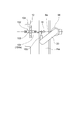
- FIG. 1 is a perspective view of a tip tool according to one embodiment. It is an outline figure showing a bone with peach meat as an example of a bone with limb. It is a top view of the tip tool (open state) concerning one embodiment. It is a top view of the tip tool (closed state) concerning one embodiment. It is a block diagram which shows the control system of the injection
- FIG. 5 is a plan view of a tip tool according to one embodiment.
- FIG. 5 is a front view of a tip tool according to an embodiment. It is an explanatory view showing the grasping state of the bone with flesh by the tip tool concerning one embodiment.
- FIG. 5 is a front view of a tip tool according to an embodiment.
- FIG. 5 is a perspective view of a tip tool (opened state) according to one embodiment. It is a top view of the tip tool (open state) concerning one embodiment. It is a perspective view of the tip tool (closed state) concerning one embodiment. It is a top view of the tip tool (closed state) concerning one embodiment. It is an explanatory view showing grasping operation of a tip tool concerning one embodiment. It is an explanatory view showing the loading operation to the loader part of the input device concerning one embodiment. It is an explanatory view showing the loading operation to the loader part of the input device concerning one embodiment. It is explanatory drawing which shows the loading operation to the loader part of the injection
- expressions that indicate that things such as “identical”, “equal” and “homogeneous” are equal states not only represent strictly equal states, but also have tolerances or differences with which the same function can be obtained. It also represents the existing state.
- expressions representing shapes such as quadrilateral shapes and cylindrical shapes not only represent shapes such as rectangular shapes and cylindrical shapes in a geometrically strict sense, but also uneven portions and chamfers within the range where the same effect can be obtained. The shape including a part etc. shall also be expressed.
- the expressions “comprising”, “having”, “having”, “including” or “having” one component are not exclusive expressions excluding the presence of other components.
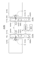
- FIG. 1 and FIG. 2 each show a bone-with-limb injection system 10 (10A, 10B) according to an embodiment.
- the imaging unit 14 (14a, 14b) for imaging the bone-with-limb W (R, L) before being inserted into the processing unit 12 (12a, 12b) and the imaging unit 14
- an image processing unit 16 capable of acquiring posture information of the boned limb W from the image of the boned limb W.
- the distal end tool 17 (17a, 17b) for gripping the boned limb W is supported, and an arm 20 (20a, 20b) capable of controlling the position and posture of the distal end tool 17 is provided.
- the control unit 22 controls the operation of the arm 20 based on the posture information acquired by the image processing unit 16 to hold the limb neck of the bone-in-the-limb W with the tip tool 17 and to the processing unit 12 in a defined direction. Let it go.
- the control unit 22 controls the operation of the arm 20 gripping the boned limb W with the tip tool 17 based on the posture information, thereby processing the plurality of boned limbs in the same direction. It can be put into section 12. As a result, the processing steps for treating a plurality of bones and bones can be uniformly performed in the processing unit 12, so automation of processing such as bone removal can be facilitated in the processing unit 12.
- the boned limb meat W can be aligned in the same direction, the amount of movement of the arm 20 can be suppressed, whereby each of the plurality of processed parts 12 is inserted as in the input system 10 (10A) shown in FIG.
- the processing unit 12 is an automatic bone removing machine, it is possible to cope with the processing speed of the automatic bone removing machine operating at high speed.
- the tip tool 17 can be simplified in structure and can be improved in terms of maintainability and system stoppage due to a failure.
- the tip tool 17 is configured of a pair of clamp pieces that can be opened and closed to each other, and the limb neck portion of the boned limb W is grasped from both sides by the pair of clamp pieces.
- the distal end tool 17 is formed of a hanger having a recess into which the limb neck can be fitted, and the limb neck is fitted and suspended in the recess.
- the processed portion 12 is a processed portion 12 (12a) dedicated to the left limb W (L) and the right. And a processing unit 12 (12b) dedicated to the limb W (R). Also, the input system 10 supplies the left limb exclusive line 10 (10a) for supplying the left limb W (L) to the processing unit 12 (12a) and the right limb W (R) to the processing unit 12 (12b) And a right extremity exclusive line 10 (10b).
- the feeding system 10 may include only one line for both right and left limbs.
- the arm 20 is configured of an arm having a multi-axis articulated joint, and can operate so that the tip tool 17 can be in any position and posture.
- the processing unit 12 is a deboning device that separates the bones and the meat of the boned leg meat W.
- posture information obtained by the image processing unit 16 shown in FIGS. 1 and 2 is front and back information in which the upper surface of the boned limb meat W placed on the grip surface and imaged by the imaging unit 14 is front or back. including.
- the control unit 22 controls the operation of the arm 20 such that the boned limb W is inserted into the processing unit 12 in the direction determined based on the posture information including the front and back surface information.
- the operation of the arm 20 is controlled based on the posture information including the front and back information. It can be introduced into the processing unit 12 so that the front or back surface of the bone with the leg always faces the same direction.
- the conveyor 24 (24 a, 24 b) for transporting the boned limb meat W to the processing unit 12
- the imaging unit 14 includes the boned limb meat W transported by the conveyor 24.
- the imaging unit 14 images the bone-with-limb W conveyed by the conveyor 24, a single imaging unit continuously images a plurality of bone-with-bones to obtain image information. As a result, it is possible to increase the speed at which a plurality of bones and bones are inserted into the processing unit 12 and to improve the processing efficiency of the processing unit 12.
- a plurality of boned limbs W are placed on the conveyor 24 with the front or back side up, and the posture information is the boned limbs imaged by the imaging unit 14 It includes front and back information in which the upper surface of W is the front surface or the back surface.
- the control unit 22 controls the operation of the arm 20 based on posture information including front and back information, and the plurality of boned limbs W are made to the processing unit 12 and either the front or back is always in the same direction with respect to the processing unit 12 Make it turn on.
- the plurality of hangers 26 are attached to the hanger conveyors 28 (28 a, 28 b) and configured to be movable to the processing unit 12.
- the plurality of boned limbs W suspended from the tip tool 17 to the plurality of hangers 26 respectively move to the processing unit 12 and are input to the input unit 32 of the processing unit 12.
- the recess 26 is formed in the hanger 26, and the boned meat W is suspended by inserting a small diameter portion below the neck of the limb into the recess 30.
- the bone-in-the-limb W is a bone-in-bone meat such as a food bird, for example, and the left leg W (L) of the bone-in-bone meat is a line 10 dedicated to the left limb.
- the attitude and the front and back surfaces are randomly placed on the conveyor 24 (24a) of (10a).
- the right leg W (R) of the boned peach meat is randomly placed on the conveyor 24 (24b) of the right-limb dedicated line 10 (10b) in attitude and front and back.
- W (Ls) represents the left leg of the boned peach meat with the surface facing upward
- W (Lb) represents the left leg of the boned peach meat with the back surface facing upward
- W (Ls) Rs) represents the right leg of the boned peach meat with the surface facing upward
- W (Lb) represents the right leg of the boned peach meat with the reverse surface facing upward.
- the control unit 22 controls the operation of the arms 20 (20a, 20b) based on posture information including front and back information, so that a plurality of bones can be detected in each of the lines 10 (10a, 10b).
- the stuffed peach meat can be suspended in order on the plurality of hangers 26 with the front side or the back side always in the same direction.
- a plurality of boned peach meats can be fed in the same direction to the respective processed parts 12 (12a, 12b).
- the plurality of boned peach meats are all hung on the hanger 26 with the knee portion N facing the back side of the pair of clamp pieces 18.
- the plurality of boned peach meat is loaded into the feeding unit 32 in the direction in which the knee portion N faces the loading unit 32 side.
- the boned limb W is obtained. Not only the same direction but also the knee N can be introduced in the same direction. Therefore, since processing in the processing unit 12 can be performed uniformly, automation of the processing unit is easy and processing speed can be increased.
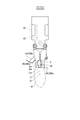
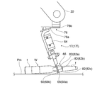
- FIG. 3 shows a tip tool 17 (17c) according to one embodiment.
- the tip tool 17 (17c) is attached to the arm 20 independently of the base 40 supported by the arm 20, the pair of clamp pieces 18 (18a, 18b) attached to the base 40, and the pair of clamp pieces 18 And an attitude adjusting member 34 (34a, 34b).
- the pair of clamp pieces 18 are configured to be openable and closable so as to be able to grip the neck portion of the boned leg meat W.
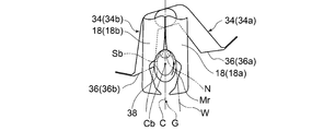
- the posture adjusting member 34 has inclined surfaces 36 (36a, 36b) which are inclined at an acute angle with respect to the center line C between the pair of clamp pieces in order to adjust the posture of the boned limb W.
- plan view is viewed from a direction (arrow b direction) orthogonal to a plane including the center line C between the pair of clamp pieces and the direction in which the pair of clamp pieces open and close.
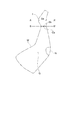
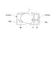
- FIG. 4 shows boned peach meat such as a chicken as an example of the boned leg meat W.
- f is a limb neck that locks onto the hanger when it is suspended by a hanger or the like.
- AA ' is a contact position (maximum diameter portion of the limb neck f) with which the inclined surface 36 contacts, as will be described later
- BB' is a grip position (limb neck) grasped by the pair of clamp pieces 18 The smallest diameter portion below f) is shown.
- Sa shows the cross section of the boned peach meat at the contact position A-A '
- Sb shows the cross section of the boned peach meat at the holding position B-B'.
- the boned limb W has a knee N which is a joint between a femur and a lower femur.
- FIG. 5A shows the state in which the pair of clamp pieces 18 are open
- FIG. 5B shows the state in which it is closed
- FIG. 6 shows a control system of the embodiment shown in FIG. 3 and FIG. 7A to 7C and 8A to 8C show the operation from the state in which the pair of clamp pieces 18 are open to the closing to grasp the boned limb W.
- ⁇ is an acute angle.
- the inclined surface 36 first contacts the boned flesh W.
- the gripping surface for example, the conveying surface of the conveyor 24
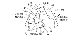
- the posture adjustment member 34 when the pair of clamp pieces 18 are in the closed state, the posture adjustment member 34 is a restraint surface existing at a position overlapping the space S in plan view. It has 38.
- FIG. 7A the space S in the second space S 2 which is located away from the first space S 1 and the first space S 1 from the attitude adjustment member 34 located attitude adjustment member 34 side by the center line C It is partitioned, constraining surface 38 in plan view, at the position overlapping the first space S 1.
- the pair of clamp pieces 18 are pivotally supported by the base 40 via the shaft 41, and as shown in FIG. 5A, the opening / closing drive unit built in the base 40 It is opened and closed by 42.
- the posture adjusting member 34 is pivotally supported by the base 40 via a shaft 44 so as to be rotatable in the opening / closing direction of the pair of clamp pieces 18 (the direction of arrow a in FIG. 3).
- the opening and closing drive unit 42 and the rotation drive unit 43 are configured by, for example, an air cylinder.
- the base 40 is attached to the arm 20.
- control unit 22 (22 a) of the present embodiment controls the arm drive unit 21 that drives the arm 20, and controls the open / close drive unit 42 and the rotation drive unit 43.
- the inclined surface 36 of the posture adjustment member 34 is positioned above the pair of clamp pieces 18 when the pair of clamp pieces 18 grip the boned limb W.
- the center of gravity G of the bone-in-the-limb W is located in the meat located below the gripping position of the pair of clamp pieces.
- the inclined surface 36 can be brought into contact with the limb neck f of the boned limb W by positioning the inclined surface 36 above the pair of clamp pieces.
- the control unit 22 controls the rotation drive unit 43 based on the posture information and the front and back information, and when the pair of clamp pieces 18 grip the boned limb W, the center line C
- the posture adjustment member 34 is pivoted so that the inclined surface 36 is located on the same side as the center of gravity G of the boned limb.
- the posture adjusting member 34 can adjust its direction along the opening and closing direction of the pair of clamp pieces 18, when the pair of clamp pieces performs a gripping operation, the inclined surface 36 is a boned limb You can adjust the timing of touching the meat.
- the posture adjustment member 34 includes a mounting portion 46 attached to the base 40, and a pair of extending portions extending in two branches from the mounting portion 46 and having inclined surfaces 36. And 48.
- the control unit 22 (22a) arranges one of the pair of extension portions 48 to be in contact with the boned limb when the upper surface of the boned limb on the grasping surface is the surface, and the upper surface of the boned limb Is the back surface, the other of the pair of extension portions 48 is arranged to be in contact with the flesh with bone.
- FIGS. 7A to 7C show that when the boned leg meat W is the right leg of the boned peach meat and the upper surface is the surface, or the boned leg meat W is the left leg of the boned peach meat and the upper surface is the reverse side.
- the operation of the posture adjustment member 34 in the case is shown.
- the inclined surface 36 (36a) of the posture adjustment member 34 (34a) contacts the boned peach meat earlier than the clamp piece 18 (18a).
- the inclined surface 36 (36a) is on the same side as the center of gravity G with respect to the gripping center Cb, and the rotational moment Mr is the center of gravity of the boned peach meat with the inclined surface 36 (36a) as the gripping center of the pair of clamp pieces It is generated to rotate from Cb to the tip side of the clamp piece.
- the boned peach meat is gripped in such a direction that the knee portion N is positioned on the back side of the clamp piece.
- the inclined surface 36 (36b) of the posture adjustment member 34 (34b) contacts the boned peach meat earlier than the clamp piece 18 (18b).
- the inclined surface 36 (36b) is on the same side as the center of gravity G with respect to the gripping center Cb, and the rotational moment Mr is the center of gravity of the boned limb W with the inclined surface 36 (36b) It is generated so as to rotate from the center Cb to the tip side of the clamp piece.
- the boned peach meat is gripped in such a direction that the knee portion N is positioned on the back side of the clamp piece.
- the knee portion N is always at the back of the clamp piece whether it is the right leg or the left leg or the upper surface is the front or back. It can be held in the same orientation located on the side. Therefore, a plurality of boned limbs W can be input to the processing unit 12 always in the same direction.
- the tip tool 17 (17d) is a boned limb when the boned limb W is gripped by the pair of clamp pieces 19 (19 a, 19 b) for gripping the boned limb W and the pair of clamp pieces 19.
- a rotation suppressing portion 50 (50a, 50b) for suppressing the rotation of the meat W is provided.
- the rotation suppressing portion 50 is provided at a position shifted with respect to the pair of clamp pieces in the direction orthogonal to the plane P including the opening and closing direction of the pair of clamp pieces 18.
- the rotation suppressing portion 50 has a protrusion 52.
- the projection 52 is provided so as to project from the first clamp piece 19 (19a) into the space S between the pair of clamp pieces when viewed from the direction perpendicular to the plane P, and to contact the boned limb W Configured
- the protrusion 52 protrudes toward the boned limb and bites into the boned limb so that the boned limb is attached. Fix the limbs immobile. Since the projection 52 is provided at a position shifted with respect to the pair of clamp pieces 19 in the direction orthogonal to the plane P, the boned limb W can be fixed in cooperation with the pair of clamp pieces 19. Thus, the boned limb W can be stably fixed. In this way, the boned limb W can be introduced to the processing unit 12 in a desired direction by moving the pair of clamp pieces 19 holding the boned limb to a desired position and posture by the arm 20. In addition, by holding the plurality of boned limbs in order with the pair of clamp pieces 19, the directions of the plurality of boned limbs W can be aligned and fed to the processing unit 12.
- the rotation suppressing portion 50 has an abutting portion 54.
- the contact portion 54 is provided on the second clamp piece 19 (19b) side with respect to the projection 52 across the center line C, and is configured to contact the boned limb W. Further, the contact portion 54 extends obliquely with respect to the direction orthogonal to the center line C so as to approach the back side of the pair of clamp pieces as it approaches the first clamp piece 19 (19a).
- the abutment portion 54 cooperates with the rotation suppressing portion 50 to press the boned limb. . Therefore, when the pair of clamp pieces is closed, the projection 52 bites into the bone with the leg from the side of the first clamp piece 19 (19a), and the contact portion 54 forms the bone from the side of the second clamp piece 19 (19b) Since the attached limb can be pressed, the boned limb W can be more stably fixed.
- the protrusion 52 is formed of a plate-like body extending in a direction intersecting the plane P. This can increase the holding power of the protrusion 52 with respect to the boned meat W.
- the boned leg meat W is a boned peach meat such as a chicken
- the boned peach meat has a recess d in the neck portion f along the axial direction. Therefore, when the projection 52 is a plate-like body extending along a direction intersecting with the plane P, the projection 52 can be inserted along the extending direction of the recess d, so that the holding force for the bone with the flesh Can be further improved.
- the abutment portion 54 is formed of a plate-like body extending in a direction intersecting the plane P. Since the area which contact part 54 contacts boned flesh W can be increased by this, the retention power to boned flesh W can be increased.
- the rotation suppressing portion 50 includes a first support wall 56a to which the projection 52 is fixed, and a second support wall 56b to which the contact portion 54 is fixed. And.
- the first support wall 56a and the second support wall 56b extend along a direction intersecting with the plane P, and as shown in FIG. It extends in the direction to widen the distance.
- first support wall 56a and the second support wall 56b in a direction in which the distance between the first support wall 56a and the second support wall 56b increases in the upward direction, It becomes easy to accommodate between the support wall 56a and the second support wall 56b, and the boned limb can be stably suspended by the pair of clamp pieces 18.
- first support wall 56a and the second support wall 56b have a U-shape bent in the direction in which both ends face each other when viewed from the orthogonal direction of the plane P, the strength of these support walls It can improve.
- the rotation suppressing portion 50 is configured of a first rotation suppressing portion 50 (50a) and a second rotation suppressing portion 50 (50b).
- the first rotation suppressing portion includes a first support wall 56a and a projection 52, and is fixed to the first clamp piece 19 (19a).
- the second rotation suppressing portion includes a second support wall 56b and an abutment portion 54, and is fixed to the second clamp piece 19 (19b).
- the first rotation suppressing portion and the second rotation suppressing portion move together with the opening and closing operation of the first clamp piece and the second clamp piece to perform the opening and closing operation, and together with the first clamp piece and the second clamp piece W can be held.
- FIG. 12 and 13 show a tip tool 17 (17e) according to one embodiment.
- the pair of clamp pieces 19 and the rotation suppressing portion 50 are attached to the arm 20 so as to be capable of reversing around the center line C, and by reversing, the first clamp pieces 19 (19 a) and the second The clamp piece 19 (19b), the protrusion 52, and the contact portion 54 are configured to be able to be interchanged with each other at their original positions.
- the control unit 22 (22 b) controls the arm drive unit 21 and the opening / closing drive unit 42 that drive the arm 20 and controls the reverse drive unit 58.
- the positions of the first clamp piece 19 (19a) and the projection 52, and the second clamp piece 19 (19b) and the contact part 54 are selected based on the back surface information.
- the depressions d in the limb neck f are in opposite positions to each other, but the depressions d are in the opposite positions.
- a plurality of boned limbs W are conveyed to arm 20 by conveyor 24 or the like.
- the bone with leg meat is a bone with peach meat and the bone with peach meat is placed randomly on the conveyor, either the upper surface of the bone with peach meat is the front (inner peach surface) or the back (outside peach surface) It is in a state of When the upper surface of the boned peach meat is the front or the back on the holding surface on which the boned peach meat is placed, the depression d in the neck f of the limb is in the reverse position on the surface or the back. According to this embodiment, even when the recess d is in the reverse position, the projection 52 can be applied to the recess d by inverting the pair of clamp pieces 19 and the rotation suppressing portion 50.
- first rotation suppressing portion 50 (50c) and the second rotation suppressing portion 50 (50d) respectively abut on the first support wall 56a having the protrusion 52.
- the second support wall 56 b having the portion 54 is integrally formed.
- First clamp pieces 19 (19a) are respectively provided at upper and lower ends of the first rotation restraining portion 50 (50c), and second clamp pieces 19 (19b) at upper and lower ends of the second rotation restraining portion 50 (50d). Is provided.
- the pair of clamp pieces 19 and the rotation suppressing portion 50 are configured to be capable of reversing 180 degrees around the center point O with respect to the base 40, and by reversing 180 degrees, the first clamp piece 19 (19a) and the second clamp The piece 19 (19b), the protrusion 52, and the contact portion 54 are configured to be able to be interchanged with each other in their original positions.
- the center point O is located at a position overlapping the center line C as viewed in a direction perpendicular to the plane P, and is located at the boundary between the first support wall 56a and the second support wall 56b.
- the first rotation suppressing portion 50 (50c) is fixed to the first clamp piece 19 (19a)
- the second rotation suppressing portion 50 (50d) is fixed to the second clamp piece 19 (19b).
- the bone-with-limb W is suspended on a pair of lower clamp pieces 19 (19a, 19b).
- the projection 52 of the first rotation suppression unit 50 (50c) can be disposed at the position where the projection 52 of the second rotation suppression unit 50 (50d) was located by reversing it 180 degrees.
- the contact portion 54 of the first rotation suppression portion can be disposed at the position where the contact portion 54 of the second rotation suppression portion was located by being inverted 180 degrees. Therefore, even if the recess d is in the reverse position on the front and back, the projection 52 can be applied to the recess d by reversing the clamp piece 19 and the rotation suppressing portion 50.
- the first support wall 56a and the second support wall 56b of the first rotation suppressing portion 50 (50c) and the second rotation suppressing portion 50 (50d) have a center point O. It extends in the direction to narrow the distance from each other as it gets away from the
- the boned limb W is a region of the first support wall 56a and the second support wall 56b located below the boned limb W in the hanging direction of the first and second rotation restraints.
- the first support wall and the second support wall which are gripped by the bone and the boned limb are gripped, extend in a direction to extend the distance from each other upward in the hanging direction of the boned limb W, so the gripping position As compared with BB ', it is easier to accommodate the largest diameter portion of the limb neck f with a larger diameter between the first and second support walls, thereby stabilizing the boned limb flesh It can be suspended.
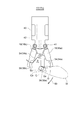
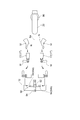
- FIGS. 14-17 illustrate a tip tool 17 (17f) according to one embodiment.
- FIGS. 14 and 15 show the pair of clamp pieces 62 (62a, 62b) in the open state
- FIGS. 16 and 17 show the pair of clamp pieces 62 (62a, 62b) in the closed state capable of grasping the boned limb W.
- the boned leg meat W shown in FIG. 16 simulates the contour of the boned peach meat of a food bird.
- the small diameter portion between the enlarged diameter portion of the limb neck f and the peach portion t is the gripping portion by the pair of clamp pieces 62.
- the tip tool 17 (17f) includes a pair of clamp pieces 62, and a support portion 64 that supports the pair of clamp pieces 62 at the base of the pair of clamp pieces 62 so as to be opened and closed. And a rotation suppressing portion 66 capable of suppressing the rotation and wobbling of the boned limb W when held by the piece 62.
- the rotation suppressing portion 66 protrudes from the surface of each clamp piece 62 (62a, 62b) along a direction orthogonal to the plane P including the opening / closing direction of the pair of clamp pieces 62 (the arrow direction in FIG. 2). Provided as.
- the tip portions 68 (68a, 68b) of the clamp pieces are located in a position closer to the center line C between the pair of clamp pieces than the rotation suppressing part 66 in the open state, and turn in the direction along the center line C. It is located at a position farther from the support portion 64 than the movement suppression portion 66, that is, at the tip end side.
- the rotation suppressing portion 66 can suppress rotation and wobble of the bone-with-limb meat W and fix it at the clamp position. Further, since the tip end portion 68 of the clamp piece 62 is on the inner side (center line C side) and the tip end side than the rotation suppressing portion 66, the tip end portion 68 of the clamp piece 62 W is inserted under the clamp site (limb neck f) of the bone-in-the-limb W, and the clamp site is scooped up. By this operation, it is possible to securely grasp the boned limb with the pair of clamp pieces 62. Further, since stable gripping is possible, the operation of the clamp piece 62 can be accelerated.
- the boned limb W is obtained. It can be suspended on the hanger 26 in a desired orientation, or can be introduced into the processing unit 12 such as a bone removing device via the hanger 26.
- the support 64 includes an actuator 70 for opening and closing the pair of clamp pieces 62.
- the actuator 70 is constituted by a hydraulic cylinder provided with a hydraulic oil inlet / outlet 72, and reciprocates the shaft 74 in the direction along the center line C.
- the pair of clamp pieces 62 is rotatably supported by the shaft 76, and the shaft 76 is pivoted by the reciprocating motion of the shaft 74, and the pair of clamp pieces 62 is opened and closed.
- a mounting plate 78 is provided on the back side of the support portion 64, and the support portion 64 is mounted to the multi-axial articulated arm 20 capable of controlling the position and posture of the support portion 64 via the mounting plate 78.
- the rotation suppressing portion 66 is provided on each of the pair of clamp pieces 62 (62a, 62b), and each rotation suppressing portion 66 has a contact piece 80 extending toward the center line C side. As shown in FIGS. 16 and 17, the contact piece 80 is configured to contact the gripped boned flesh W when the pair of clamp pieces 62 are in the closed state. According to this embodiment, when the boned limb W is gripped by the pair of clamp pieces 62, the boned limb W can be fixed by the contact piece 80, so that the rotational wiggle of the boned limb W can be prevented. .
- the contact piece 80 is formed of a plate-like body extending in a direction intersecting the opening / closing direction plane. Since the contact piece 80 extends along the longitudinal direction of the griped limb neck, it can be more firmly fixed to the clamp piece.
- FIG. 17 shows a state in which the limb neck f of a boned peach meat of a food such as a chicken is gripped by a pair of clamp pieces 62 as the boned limb W.
- the boned leg meat W is a boned peach meat of a food bird, a recess d is present in the neck portion f in the longitudinal direction.
- the contact piece 80 is a plate-like body extending along a direction (a direction perpendicular to the drawing in the drawing) intersecting the opening / closing direction plane, one side of the contact piece 80 is inserted into the recess d. Can be further improved.
- the rotation suppressing portion 66 is configured to include the wall portion 82 (82a, 82b, 82c).
- the wall portions 82 are respectively provided on the pair of clamp pieces 62 so as to face each other across the space S between the pair of clamp pieces 62.
- the tip portions 68 (68a, 68b) of the clamp pieces 62 (62a, 62b) are located inside (closer to the center line C) than the wall 82 in the open state and in the direction along the center line C It is located farther from the support 64 than the wall 82 (tip side).
- the strength of the clamp piece 62 can be enhanced by the presence of the wall portion 82, and the wall portion 82 is in the above-described positional relationship with the tip portion 68 of the clamp piece 62.
- the rotation suppressing portion 66 can support the boned limb W that has been raised by the tip portion 68. By this, it is possible to grip the boned leg meat W with certainty.
- the wall 82 extends along at least a portion of the contour of each clamp piece 62 (62a, 62b) away from the center line C, so that the wall of the clamping operation of the clamp piece 62 may be disturbed.
- the movement of the clamp piece 62 can be assisted to prevent the boned human flesh W from coming off the clamp piece 62.
- the wall 82 constituting the rotation suppressing part 66 is configured by the first wall 82 (82a), the second wall 82 (82b), and the third wall 82 (82c).
- the first wall 82 (82 a) extends along the center line C in the closed state of the pair of clamp pieces 62.
- the second wall 82 (82b) is connected to the end of the first wall 82 (82a) on the support 64 side, and extends from the first wall 82 (82a) by bending toward the center line C .
- the third wall 82 (82c) is connected to the end of the first wall 82 (82a) on the opposite side to the support 64 and is bent from the first wall 82 (82a) toward the center line C To extend.
- the contact piece 80 is disposed between the second wall 82 (82b) and the third wall 82 (82c).
- the first wall 82 (82a), the second wall 82 (82b) and the third wall 82 (82c) surround the boned limb W grasped by the clamp piece 62. Since it is disposed, the boned limb W, which is picked up by the tip 68 of the clamp piece 62 at the initial stage of the gripping operation, is moved to the first wall 82 (82a), the second wall 82 (82b) and the third wall 82 ( At 82c), the boned flesh W can be prevented from coming off the tip 68, and the rotation and wobble of the griped boned flesh W can be suppressed.
- the second wall 82 (82 b) and the third wall 82 (82 c) are inclined relative to the center line C in the closed state of the pair of clamp pieces 62, and third wall portion 82 an inclination angle alpha 3 relative to the center line C of (82c) the inclination angle alpha 2 smaller relative to the center line C of the second wall portion 82 (82b) ( ⁇ 3 ⁇ ⁇ 2).
- the third wall 82 (82c) can be approached to the gripping surface.
- the third wall 82 (82 c) can be inserted below the boned limb W picked up by the distal end 68 of the clamp piece 62, and the boned limb W can be prevented from coming off from the distal end 68. By this, it is possible to grip the boned leg meat W with certainty.
- FIG. 18 shows a scene in which the bone-with-limb W placed on the gripping surface Pm is gripped and transferred by the end tool 17 (17f).
- the distal end tool 17 (17f) is attached to the arm 20 via the attachment plate 78.
- the arm 20 is configured by a multi-axis articulated joint, and can control the position and attitude of the tip tool 17 (17 f).
- the clamp device side mounting portion 78a of the mounting plate 78 is inclined at an angle ⁇ with respect to the arm side mounting portion 78b. For this reason, the clamp piece 62 is inclined at an angle ⁇ with respect to the gripping surface Pm, and this inclination facilitates the approaching operation of the clamp device 10 with respect to the boned flesh W.
- the tip portions 68 (68a, 68b) of the clamp pieces 62 are configured to overlap one another when viewed from the direction orthogonal to the plane P in the closed state.
- the tip portions of the clamp pieces 62 can be closed before the pair of clamp pieces 62 are closed, it is possible to prevent the drop of the boned limb W from the tip side of the clamp pieces.
- the pair of tip portions 68 (68 a, 68 b) are arranged to be shifted in the direction orthogonal to the plane P. This allows the tips 68 (68a, 68b) to overlap one another.
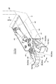
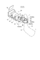
- a loader unit 90 is provided for receiving the bone-with-limb W from the tip tool 17 (17f) and delivering it to the processing unit 12 side.
- the loader unit 90 includes a pivot shaft 92 and three or more hangers 94 which are pivotable about the pivot shaft 92 and arranged at equal angular intervals with respect to the pivot shaft 92. .
- suspension is performed based on the posture information of the boned limb W obtained by the image processing unit 16.
- the hanger 94 the operation of the arm 20 and the tip tool 17 (17f) can be simplified.
- the suspension speed to the hanger 94 can be increased, or the injection speed of the bone-with-limb W to be injected into the processing unit 12 can be increased.
- the arm 20 and the tip tool 17 (17f) are controlled by the control unit 22 when the boned limb W is suspended from the gripping surface Pm to the hanger 94 by the tip tool 17 (17f). Indicates the operation.
- FIG. 21 shows operations of the arm 20 and the tip tool 17 (17f) as a comparative example.
- the control unit 22 rotates the rotation shaft 92 and the arm 20 when the upper surface of the boned limb W determined by the image processing unit 16 is a surface.
- the boned limb W is suspended from the end tool 17 (17f) to the hanger 94 on one side with respect to a reference line Ba connecting the pedestal 96 which supports it, and the boned limb W determined by the image processing unit 16
- the upper surface is the back surface, it is configured to control the boned limb W to be suspended from the tip tool 17 (17f) to the hanger 94 on the other side with respect to the reference line Ba.
- three hangers 94 are attached to the pivot shaft 92 at equal angular intervals of 120 degrees, and in the embodiment shown in FIG. 20, four hangers 94 at equal angular intervals of 90 degrees.
- the rotary shaft 92 is attached.
- the tip tool 17 (17f) grips the boned limb W and suspends on the hanger 94 (94a), and the upper surface of the boned limb W has a back surface
- the tip tool 17 (17f) grips the boned limb W and suspends it on the hanger 94 (94b).
- the operation of the arm 20 and the tip tool 17 (17f) can be simplified, so that the suspension speed to the hanger 94 or the input speed to the processing unit 12 can be increased. That is, it is possible to suspend on the hanger 94 without largely changing the angle of the arm 20 with respect to the reference line Ba and the angle of the clamp piece 62 with respect to the arm 20.
- the boned flesh W has a different orientation of the knee N when the upper surface is the front or back surface. The difference in the direction of the knee N can be offset by suspending the bone-with-limb W on the hanger 94 at different positions with respect to the reference line Ba, and the movement of the arm 20 and the tip tool 17 (17f) can be simplified. .
- the tip tool 17 (17f) can be suspended on the hanger 94 simply by tilting it 30 degrees with respect to the reference line Ba.
- the tip tool 17 (17f) can be suspended on the hanger 94 only by inclining it by 90 degrees with respect to the reference line Ba.
- the tip tool 17 (17f) may be rotated by 120 degrees in FIG. 19 or 90 degrees in FIG.
- the rotation time of 94 can be shortened. Therefore, the suspension speed and the input speed can be increased, and the throughput can be increased.
- the rotating shaft 103 of the loader portion 102 is disposed on the reference line Ba, and for example, two or four hangers 104 are provided at equal angles on the rotating shaft 103. ing.
- the boned flesh W on the gripping surface Pm (for example, the conveyor conveyance surface) is always located in front of the reference line Ba regardless of whether the upper surface of the boned flesh W is the front or back by the tip tool 100 It is suspended by the hanger 104 (104a). At this time, as shown in the figure, it is necessary to largely change the angle of the arm 20 with respect to the reference line Ba and the angle of the tip tool 100 with respect to the arm 20.
- each hanger 104 when the suspended boned limb W is inserted into the processing unit 12, it is necessary to rotate the hanger 104 by 180 degrees. Therefore, there is a problem that the suspension speed and the injection speed per bone and limb can be increased as compared with the above embodiment.
- the loader unit 90 is provided between the tip end tool 17 (17f) and the processing unit 12, but instead of the processing unit 12, a plurality of hangers 26 may be provided as shown in FIG.
- the hanger conveyor 28 may be provided, and the loader unit 90 may be used to transfer the boned leg meat W from the tip tool 17 to the plurality of hangers 26.
- the bone-with-limb W is not limited to food birds, but includes all bone-with-bones legs such as legs, arms and the like of domestic animals such as pigs, cows and sheep.
- the operation of aligning and injecting the directions of a plurality of bone-in-bones can be automated by a machine without manual operation.
Landscapes
- Engineering & Computer Science (AREA)
- Life Sciences & Earth Sciences (AREA)
- Food Science & Technology (AREA)
- Wood Science & Technology (AREA)
- Zoology (AREA)
- Robotics (AREA)
- Mechanical Engineering (AREA)
- Processing Of Meat And Fish (AREA)
- Manipulator (AREA)
Abstract
Priority Applications (12)
| Application Number | Priority Date | Filing Date | Title |
|---|---|---|---|
| ES18864870T ES2882778T3 (es) | 2017-10-06 | 2018-10-05 | Sistema para cargar carne de pata sobre el hueso |
| EP18864870.3A EP3545769B1 (fr) | 2017-10-06 | 2018-10-05 | Système de chargement de viande de cuisse sur l'os |
| JP2019524467A JP6689458B2 (ja) | 2017-10-06 | 2018-10-05 | 骨付き肢肉の投入システム |
| DK18864870.3T DK3545769T3 (da) | 2017-10-06 | 2018-10-05 | System til at lade benkød på knoglen |
| RU2020109670A RU2737554C1 (ru) | 2017-10-06 | 2018-10-05 | Загрузочная система для мяса конечности с костью |
| AU2018344737A AU2018344737C1 (en) | 2017-10-06 | 2018-10-05 | Loading system for bone-in limb meat |
| KR1020197018358A KR102286790B1 (ko) | 2017-10-06 | 2018-10-05 | 뼈 있는 다리살의 투입 시스템 |
| BR112020003357-0A BR112020003357B1 (pt) | 2017-10-06 | 2018-10-05 | Sistema de carregamento para carne de membro com osso |
| CN201880059104.6A CN111278285B (zh) | 2017-10-06 | 2018-10-05 | 带骨肢肉的放入系统 |
| PL18864870T PL3545769T3 (pl) | 2017-10-06 | 2018-10-05 | Układ do ładowania mięsa nogi z kością |
| MX2020002463A MX2020002463A (es) | 2017-10-06 | 2018-10-05 | Sistema de carga para carne de extremidad con hueso. |
| US16/463,098 US10681918B2 (en) | 2017-10-06 | 2018-10-05 | Loading system for bone-in limb meat |
Applications Claiming Priority (2)
| Application Number | Priority Date | Filing Date | Title |
|---|---|---|---|
| JP2017195872 | 2017-10-06 | ||
| JP2017-195872 | 2017-10-06 |
Publications (1)
| Publication Number | Publication Date |
|---|---|
| WO2019070057A1 true WO2019070057A1 (fr) | 2019-04-11 |
Family
ID=65995186
Family Applications (1)
| Application Number | Title | Priority Date | Filing Date |
|---|---|---|---|
| PCT/JP2018/037378 WO2019070057A1 (fr) | 2017-10-06 | 2018-10-05 | Système de chargement de viande de cuisse sur l'os |
Country Status (15)
| Country | Link |
|---|---|
| US (1) | US10681918B2 (fr) |
| EP (1) | EP3545769B1 (fr) |
| JP (1) | JP6689458B2 (fr) |
| KR (1) | KR102286790B1 (fr) |
| CN (1) | CN111278285B (fr) |
| AU (1) | AU2018344737C1 (fr) |
| BR (1) | BR112020003357B1 (fr) |
| CL (1) | CL2020000405A1 (fr) |
| DK (1) | DK3545769T3 (fr) |
| ES (1) | ES2882778T3 (fr) |
| HU (1) | HUE055804T2 (fr) |
| MX (1) | MX2020002463A (fr) |
| PL (1) | PL3545769T3 (fr) |
| RU (1) | RU2737554C1 (fr) |
| WO (1) | WO2019070057A1 (fr) |
Cited By (1)
| Publication number | Priority date | Publication date | Assignee | Title |
|---|---|---|---|---|
| EP3653059B1 (fr) | 2018-10-05 | 2022-03-16 | Mayekawa Mfg. Co., Ltd. | Dispositif de serrage pour viande de membres d'animaux non désossée, dispositif de chargement pour la viande de membres d'animaux non désossée, et procédé de serrage pour la viande de membres d'animaux non désossée |
Citations (6)
| Publication number | Priority date | Publication date | Assignee | Title |
|---|---|---|---|---|
| JP2001149001A (ja) * | 1999-11-25 | 2001-06-05 | Mayekawa Mfg Co Ltd | 食鶏腿肉脱骨用自動筋入れ方法とその装置 |
| JP2005304314A (ja) * | 2004-04-16 | 2005-11-04 | Shokuniku Seisan Gijutsu Kenkyu Kumiai | 脊柱除去方法および脊柱除去装置 |
| WO2008136513A1 (fr) * | 2007-05-02 | 2008-11-13 | Mayekawa Mfg. Co., Ltd. | Procédé de découpe de viande et appareil destiné aux carcasses de viande et programme destiné à une procédure de découpe de viande |
| WO2009139031A1 (fr) | 2008-05-12 | 2009-11-19 | 株式会社前川製作所 | Procédé et dispositif de chargement de viande avec os et programme pour opération de chargement |
| JP2013507101A (ja) | 2010-03-30 | 2013-03-04 | 株式会社前川製作所 | 骨付き腿肉の脱骨方法及び装置 |
| WO2014064773A1 (fr) * | 2012-10-23 | 2014-05-01 | 株式会社前川製作所 | Système de tri droite/gauche pour des parties de membres de carcasse de porc |
Family Cites Families (21)
| Publication number | Priority date | Publication date | Assignee | Title |
|---|---|---|---|---|
| US3376600A (en) * | 1966-02-01 | 1968-04-09 | Internat Agri Systems Inc | Mechanical discharge shackle for fowls and the like |
| DE3743541A1 (de) * | 1987-12-22 | 1989-07-06 | Nordischer Maschinenbau | Einrichtung zum abstreifen des fleisches von den extremitaeten von gefluegel |
| SU1788882A3 (en) * | 1991-04-30 | 1993-01-15 | Гoлobhoe Kohctpуktopckoe Бюpo Пpeccob-Abtomatob Пpoизboдctbehhoгo Oб'eдиhehия "Пpeccmaш" | Boning mechanism |
| NL1011044C1 (nl) | 1999-01-15 | 2000-07-18 | Stork Pmt | Werkwijze en inrichting voor het verwerken van een slachtdier. |
| NL1011677C2 (nl) | 1999-03-26 | 2000-09-27 | Machf Meyn Bv | Draaghaak voor gevogelte. |
| ATE277519T1 (de) * | 1999-08-27 | 2004-10-15 | K J Maskinfabriken As | Anschaubasiertes, automatisches zerteilungssystem |
| NL1015742C2 (nl) | 2000-07-19 | 2002-02-01 | Holland United Food Proc Equip | Werkwijze en inrichting voor het verwerken van te slachten pluimvee. |
| DE10216174A1 (de) * | 2002-04-12 | 2003-10-30 | Imt Robot Ag | Verfahren zur automatisierten Gruppierung von Objekten |
| GB2415944A (en) | 2004-07-03 | 2006-01-11 | Koorosh Khodabandehloo | Apparatus fro moving products using camera and flat gripper |
| US7588487B1 (en) * | 2005-02-25 | 2009-09-15 | Born Jr Kenneth A | Game skinning pliers |
| NL1030388C2 (nl) * | 2005-11-10 | 2007-05-16 | Systemate Group Bv | Ontbener. |
| US8192258B2 (en) * | 2005-12-09 | 2012-06-05 | Stork Pmt B.V. | Method and device for processing a carcass part of slaughtered poultry |
| IS8494A (is) | 2006-05-31 | 2008-12-02 | Valka Ehf | Griparmur á pjark fyrir matvaeli |
| WO2008096459A1 (fr) | 2007-02-06 | 2008-08-14 | Mayekawa Mfg. Co., Ltd. | Procédé et appareil pour désosser une partie de bras ou de jambe |
| EP2174551A1 (fr) | 2008-10-09 | 2010-04-14 | Cabinplant A/S | Procédé de traitement du poisson et usine de traitement du poisson |
| EP2413702B1 (fr) * | 2009-04-03 | 2018-05-30 | Robotic Technologies Limited | Procédé et appareil de découpe de carcasse |
| ES2719762T3 (es) * | 2009-12-17 | 2019-07-12 | Marel Meat Bv | Sistema y procedimiento para procesar animales sacrificados y / o partes de los mismos |
| BR112014011702A2 (pt) * | 2011-11-14 | 2017-05-30 | Topkip Bv | método para manipulação de aves, como frangos, perua, gansos, patos e codornizes, e instalação para manipulação de aves, tais como frangos, perus, gansos, patos e codornizes |
| EP2826376B1 (fr) * | 2012-03-13 | 2017-01-18 | Mayekawa Mfg. Co., Ltd. | Dispositif et procédé de transport pour de la viande non désossée et système de désossement pour de la viande non désossée utilisé avec ledit dispositif |
| RU2541406C1 (ru) * | 2013-09-10 | 2015-02-10 | Государственное научное учреждение Всероссийский научно-исследовательский институт птицеперерабатывающей промышленности Россельхозакадемии (ГНУ ВНИИПП Россельхозакадемии) | Способ производства мяса механической обвалки разного качества и устройство для его осуществления |
| BR112020003358B1 (pt) * | 2017-10-06 | 2024-03-12 | Mayekawa Mfg. Co., Ltd | Dispositivo de fixação para carne de membro com osso, dispositivo de carregamento para carne de membro com osso e método de fixação para carne de membro com osso |
-
2018
- 2018-10-05 RU RU2020109670A patent/RU2737554C1/ru active
- 2018-10-05 KR KR1020197018358A patent/KR102286790B1/ko active IP Right Grant
- 2018-10-05 AU AU2018344737A patent/AU2018344737C1/en active Active
- 2018-10-05 EP EP18864870.3A patent/EP3545769B1/fr active Active
- 2018-10-05 HU HUE18864870A patent/HUE055804T2/hu unknown
- 2018-10-05 MX MX2020002463A patent/MX2020002463A/es unknown
- 2018-10-05 CN CN201880059104.6A patent/CN111278285B/zh active Active
- 2018-10-05 PL PL18864870T patent/PL3545769T3/pl unknown
- 2018-10-05 DK DK18864870.3T patent/DK3545769T3/da active
- 2018-10-05 JP JP2019524467A patent/JP6689458B2/ja active Active
- 2018-10-05 WO PCT/JP2018/037378 patent/WO2019070057A1/fr unknown
- 2018-10-05 ES ES18864870T patent/ES2882778T3/es active Active
- 2018-10-05 BR BR112020003357-0A patent/BR112020003357B1/pt active IP Right Grant
- 2018-10-05 US US16/463,098 patent/US10681918B2/en active Active
-
2020
- 2020-02-18 CL CL2020000405A patent/CL2020000405A1/es unknown
Patent Citations (6)
| Publication number | Priority date | Publication date | Assignee | Title |
|---|---|---|---|---|
| JP2001149001A (ja) * | 1999-11-25 | 2001-06-05 | Mayekawa Mfg Co Ltd | 食鶏腿肉脱骨用自動筋入れ方法とその装置 |
| JP2005304314A (ja) * | 2004-04-16 | 2005-11-04 | Shokuniku Seisan Gijutsu Kenkyu Kumiai | 脊柱除去方法および脊柱除去装置 |
| WO2008136513A1 (fr) * | 2007-05-02 | 2008-11-13 | Mayekawa Mfg. Co., Ltd. | Procédé de découpe de viande et appareil destiné aux carcasses de viande et programme destiné à une procédure de découpe de viande |
| WO2009139031A1 (fr) | 2008-05-12 | 2009-11-19 | 株式会社前川製作所 | Procédé et dispositif de chargement de viande avec os et programme pour opération de chargement |
| JP2013507101A (ja) | 2010-03-30 | 2013-03-04 | 株式会社前川製作所 | 骨付き腿肉の脱骨方法及び装置 |
| WO2014064773A1 (fr) * | 2012-10-23 | 2014-05-01 | 株式会社前川製作所 | Système de tri droite/gauche pour des parties de membres de carcasse de porc |
Non-Patent Citations (1)
| Title |
|---|
| See also references of EP3545769A4 |
Cited By (1)
| Publication number | Priority date | Publication date | Assignee | Title |
|---|---|---|---|---|
| EP3653059B1 (fr) | 2018-10-05 | 2022-03-16 | Mayekawa Mfg. Co., Ltd. | Dispositif de serrage pour viande de membres d'animaux non désossée, dispositif de chargement pour la viande de membres d'animaux non désossée, et procédé de serrage pour la viande de membres d'animaux non désossée |
Also Published As
| Publication number | Publication date |
|---|---|
| HUE055804T2 (hu) | 2021-12-28 |
| MX2020002463A (es) | 2020-07-13 |
| US20200068907A1 (en) | 2020-03-05 |
| JPWO2019070057A1 (ja) | 2019-11-14 |
| AU2018344737C1 (en) | 2021-09-30 |
| PL3545769T3 (pl) | 2021-09-27 |
| DK3545769T3 (da) | 2021-08-02 |
| EP3545769A1 (fr) | 2019-10-02 |
| RU2737554C1 (ru) | 2020-12-01 |
| AU2018344737A1 (en) | 2020-02-13 |
| ES2882778T3 (es) | 2021-12-02 |
| CN111278285A (zh) | 2020-06-12 |
| CL2020000405A1 (es) | 2020-07-10 |
| CN111278285B (zh) | 2021-08-17 |
| EP3545769B1 (fr) | 2021-07-07 |
| KR102286790B1 (ko) | 2021-08-06 |
| BR112020003357A2 (pt) | 2020-08-18 |
| JP6689458B2 (ja) | 2020-04-28 |
| AU2018344737B2 (en) | 2021-04-22 |
| BR112020003357B1 (pt) | 2024-02-27 |
| KR20190086012A (ko) | 2019-07-19 |
| US10681918B2 (en) | 2020-06-16 |
| EP3545769A4 (fr) | 2020-02-26 |
Similar Documents
| Publication | Publication Date | Title |
|---|---|---|
| JP6689457B2 (ja) | 骨付き肢肉のクランプ装置、骨付き肢肉の投入装置及び骨付き肢肉のクランプ方法 | |
| WO2019070057A1 (fr) | Système de chargement de viande de cuisse sur l'os | |
| JP6689459B1 (ja) | 骨付き肢肉のクランプ装置、骨付き肢肉の投入装置及び骨付き肢肉のクランプ方法 | |
| WO2019070060A1 (fr) | Dispositif de serrage pour la viande de cuisse sur l'os, dispositif de chargement pour la viande de cuisse sur l'os, et procédé de serrage de viande de cuisse sur l'os |
Legal Events
| Date | Code | Title | Description |
|---|---|---|---|
| ENP | Entry into the national phase |
Ref document number: 2019524467 Country of ref document: JP Kind code of ref document: A |
|
| 121 | Ep: the epo has been informed by wipo that ep was designated in this application |
Ref document number: 18864870 Country of ref document: EP Kind code of ref document: A1 |
|
| ENP | Entry into the national phase |
Ref document number: 20197018358 Country of ref document: KR Kind code of ref document: A |
|
| ENP | Entry into the national phase |
Ref document number: 2018864870 Country of ref document: EP Effective date: 20190627 |
|
| ENP | Entry into the national phase |
Ref document number: 2018344737 Country of ref document: AU Date of ref document: 20181005 Kind code of ref document: A |
|
| REG | Reference to national code |
Ref country code: BR Ref legal event code: B01A Ref document number: 112020003357 Country of ref document: BR |
|
| NENP | Non-entry into the national phase |
Ref country code: DE |
|
| ENP | Entry into the national phase |
Ref document number: 112020003357 Country of ref document: BR Kind code of ref document: A2 Effective date: 20200218 |