WO2019070057A1 - System for loading leg meat on the bone - Google Patents
System for loading leg meat on the bone Download PDFInfo
- Publication number
- WO2019070057A1 WO2019070057A1 PCT/JP2018/037378 JP2018037378W WO2019070057A1 WO 2019070057 A1 WO2019070057 A1 WO 2019070057A1 JP 2018037378 W JP2018037378 W JP 2018037378W WO 2019070057 A1 WO2019070057 A1 WO 2019070057A1
- Authority
- WO
- WIPO (PCT)
- Prior art keywords
- limb
- boned
- pair
- bone
- clamp pieces
- Prior art date
Links
Images


Classifications
-
- A—HUMAN NECESSITIES
- A22—BUTCHERING; MEAT TREATMENT; PROCESSING POULTRY OR FISH
- A22B—SLAUGHTERING
- A22B7/00—Slaughterhouse arrangements
- A22B7/001—Conveying arrangements
- A22B7/005—Means for transferring carcasses from a conveying unit to a different one, e.g. hooking, unhooking
-
- A—HUMAN NECESSITIES
- A22—BUTCHERING; MEAT TREATMENT; PROCESSING POULTRY OR FISH
- A22C—PROCESSING MEAT, POULTRY, OR FISH
- A22C15/00—Apparatus for hanging-up meat or sausages
-
- A—HUMAN NECESSITIES
- A22—BUTCHERING; MEAT TREATMENT; PROCESSING POULTRY OR FISH
- A22C—PROCESSING MEAT, POULTRY, OR FISH
- A22C17/00—Other devices for processing meat or bones
-
- A—HUMAN NECESSITIES
- A22—BUTCHERING; MEAT TREATMENT; PROCESSING POULTRY OR FISH
- A22C—PROCESSING MEAT, POULTRY, OR FISH
- A22C17/00—Other devices for processing meat or bones
- A22C17/0073—Other devices for processing meat or bones using visual recognition, X-rays, ultrasounds, or other contactless means to determine quality or size of portioned meat
-
- A—HUMAN NECESSITIES
- A22—BUTCHERING; MEAT TREATMENT; PROCESSING POULTRY OR FISH
- A22C—PROCESSING MEAT, POULTRY, OR FISH
- A22C17/00—Other devices for processing meat or bones
- A22C17/0093—Handling, transporting or packaging pieces of meat
-
- A—HUMAN NECESSITIES
- A22—BUTCHERING; MEAT TREATMENT; PROCESSING POULTRY OR FISH
- A22C—PROCESSING MEAT, POULTRY, OR FISH
- A22C17/00—Other devices for processing meat or bones
- A22C17/04—Bone cleaning devices
-
- A—HUMAN NECESSITIES
- A22—BUTCHERING; MEAT TREATMENT; PROCESSING POULTRY OR FISH
- A22C—PROCESSING MEAT, POULTRY, OR FISH
- A22C21/00—Processing poultry
-
- A—HUMAN NECESSITIES
- A22—BUTCHERING; MEAT TREATMENT; PROCESSING POULTRY OR FISH
- A22C—PROCESSING MEAT, POULTRY, OR FISH
- A22C21/00—Processing poultry
- A22C21/0053—Transferring or conveying devices for poultry
-
- B—PERFORMING OPERATIONS; TRANSPORTING
- B25—HAND TOOLS; PORTABLE POWER-DRIVEN TOOLS; MANIPULATORS
- B25J—MANIPULATORS; CHAMBERS PROVIDED WITH MANIPULATION DEVICES
- B25J11/00—Manipulators not otherwise provided for
- B25J11/0045—Manipulators used in the food industry
-
- B—PERFORMING OPERATIONS; TRANSPORTING
- B25—HAND TOOLS; PORTABLE POWER-DRIVEN TOOLS; MANIPULATORS
- B25J—MANIPULATORS; CHAMBERS PROVIDED WITH MANIPULATION DEVICES
- B25J9/00—Programme-controlled manipulators
- B25J9/0093—Programme-controlled manipulators co-operating with conveyor means
-
- B—PERFORMING OPERATIONS; TRANSPORTING
- B25—HAND TOOLS; PORTABLE POWER-DRIVEN TOOLS; MANIPULATORS
- B25J—MANIPULATORS; CHAMBERS PROVIDED WITH MANIPULATION DEVICES
- B25J9/00—Programme-controlled manipulators
- B25J9/16—Programme controls
- B25J9/1694—Programme controls characterised by use of sensors other than normal servo-feedback from position, speed or acceleration sensors, perception control, multi-sensor controlled systems, sensor fusion
- B25J9/1697—Vision controlled systems
Definitions
- the present disclosure relates to an injection system for injecting a bone-in-limb meat into a processing unit such as a deboning device.
- Patent Document 1 discloses an automatic bone removing apparatus for removing bones from peach meat with bones. This device intermittently transports between a plurality of processing stations while suspending boned peach meat on a clamp device, and sequentially performs steps such as scoring of boned peach meat and separation of bone meat at each station. It enables automatic bone removal.
- Patent Document 2 discloses a clamp device for gripping a boned peach meat conveyed by a conveyor with a multi-axis articulated arm and suspending the same from a hanger.
- Patent Literatures 1 and 2 do not disclose means for automating the operation of aligning and feeding the directions of a plurality of bones and limbs to an automatic bone removing device or the like.
- a system for feeding bones and legs An injection system for inserting a boned limb into a processing unit, An imaging unit for imaging the bone-with-limb prior to insertion into the processing unit; An image processing unit capable of acquiring posture information of the bone-with-limb from the image of the bone-with-limb imaged by the imaging unit; A tip tool for grasping the boned limb meat; An arm supporting the tip tool and capable of controlling the position and attitude of the tip tool; A control unit configured to control the operation of at least the arm based on the posture information acquired by the image processing unit to grip the neck of the limb with the bone, and to inject it into the processing unit in a predetermined direction; Equipped with
- the term "bone-tailed flesh” includes the site of the hand and limbs of the carcass of a food animal and animal, and includes, for example, a peach site or a carcass site.
- the “tip tool” includes any configuration capable of grasping (including suspending) boned flesh and is not limited to a specific configuration.
- a plurality of boned limbs are processed in the same direction by controlling at least the operation of the arm holding the boned limb with the tip tool on the basis of the posture information. It can be introduced. This makes it possible to uniformly perform a plurality of processing steps on the flesh with bones at the processing unit, and thus facilitates automation of processing such as bone removal at the processing unit.
- the posture information includes front and back information in which the upper surface of the boned limb flesh imaged by the imaging unit is the front surface or the back surface
- the control unit is configured to control at least an operation of the arm so as to insert the bone-with-limb in the processing unit based on the posture information including the front and back surface information.
- a conveyor for conveying the boned limb to the processing unit is configured to image the bone-in-the-bone flesh transported by the conveyor.
- the imaging unit since the imaging unit images the boned limb transported by the conveyor, a single imaging unit continuously images a plurality of boned limbs to obtain image information. As a result, it is possible to increase the speed at which a plurality of bones and legs are inserted into the processing unit, and thereby the processing efficiency of the processing unit can be improved.
- the posture information includes front and back information in which the upper surface of the bone-with-limb flesh imaged by the imaging unit is the front or back
- the control unit controls the operation of the arm based on the posture information including the front and back information, and the plurality of bones and bones are attached to the processing unit and either the front or back is always to the processing unit. It is configured to feed in the same direction.
- the apparatus further comprises a plurality of hangers that can suspend the boned limb and transport the boned limb to the processing unit.
- the control unit is configured to control the movement of the arm and to suspend the plurality of boned limbs on each of the plurality of hangers such that either the front or the back always faces in the same direction.
- the plurality of boned limbs are surfaced on the processing portion through the hangers. Or it can be injected so that either of the back side always points in the same direction.
- any one of the configurations (1) to (3) Only one of the right and left limbs of the boned limb is introduced into the processing unit.
- the configuration of the above (4) by inserting only one of the right and left limbs into the processing portion, when the bone-with-limb is inserted into the processing portion, the knee portion can also be loaded in the same direction. Therefore, since processing in the processing unit can be uniformly performed, automation is easy and processing speed can be increased.
- the loader portion includes a pivoting axis, and three or more hangers which are pivotable about the pivoting axis and arranged at equal angular intervals with respect to the pivoting axis.
- the control unit may perform, on one side with respect to a reference line connecting the pivot shaft and a pedestal that movably supports the arm.
- the boned limb is suspended from the tip tool to the hanger, and the upper surface of the boned limb imaged by the imaging unit is the back surface, the boned limb on the other side with respect to the reference line It is configured to control suspension from the tip tool to the hanger.
- the boned limb is suspended on the hanger at different positions bordering on the reference line when the upper surface of the boned limb is the front and the back. , The operation of the arm and the tip tool can be simplified. By this, the suspension speed to a hanger or the conveyance amount to a process part can be increased.
- the tip tool is A base supported by the arm; A pair of clamp pieces attached to the base and configured to grip boned meat; It has an inclined surface attached to the base independently from the pair of clamp pieces and inclined at an acute angle with respect to the center line between the pair of clamp pieces, and an attitude for adjusting the posture of the bone with meat
- An adjustment member Including When the pair of clamp pieces are in the open state, at least a part of the inclined surface of the posture adjustment member is arranged to overlap a space formed between the pair of clamp pieces in plan view.
- a planar view means seeing from a direction orthogonal to the plane including the center line between the pair of clamp pieces and the direction in which the pair of clamp pieces open and close.
- the tip tool is A pair of clamp pieces including a first clamp piece and a second clamp piece, which can be opened and closed so as to grip boned meat;
- a rotation suppressing portion provided at a position shifted with respect to the pair of clamp pieces in a direction orthogonal to a plane including the opening and closing direction of the pair of clamp pieces, for suppressing rotation of the boned meat ,
- the rotation suppressing portion is provided so as to protrude from the first clamp piece into the space between the pair of clamp pieces when viewed in a direction perpendicular to the plane, and configured to contact the boned meat. Including the protruding portion.
- the projection projects toward the boned limb and bites into the boned limb. It can fix bones and limbs so as not to move.
- the projection is provided at a position offset with respect to the pair of clamp pieces in a direction orthogonal to a plane including the opening and closing direction of the pair of clamp pieces, so that the boned limb meat in cooperation with the pair of clamp pieces It is possible to fix bones and limbs stably by this.
- the boned limb can be introduced into the processing section in the desired direction, and a plurality of boned limbs can be inserted by the pair of clamp pieces.
- grasping in sequence it is possible to align the directions of the plurality of bones and limbs with one another and to feed them into the processing unit.
- the tip tool is A pair of clamp pieces for gripping boned meat, A support that supports the pair of clamp pieces openably and closably at the base of each of the clamp pieces; It is provided so as to project from the surface of the pair of clamp pieces along a direction orthogonal to a plane including the opening and closing direction of the pair of clamp pieces, and rotation suppression for suppressing rotation of the boned meat Department, Including Each of the pair of clamp pieces is a position closer to the center line between the pair of clamp pieces than the rotation suppressing portion in the open state of the pair of clamp pieces, and a direction along the center line And a tip end portion at a position farther from the support portion than the rotation suppression portion.
- the rotation suppressing portion when the boned limb is gripped by the pair of clamp pieces, the rotation suppressing portion can suppress rotation and wobble of the boned limb and fix it at the clamp position.
- the tip end of the clamp piece is on the inner side (the center line side) and the tip end side (the side farther from the support portion) than the rotation suppressing portion, the tip end of the clamp piece It is inserted under the boned limb with the attached limb and scoops up the boned limb. By this operation, it is possible to reliably grasp the boned limb with a pair of clamp pieces. In addition, since stable gripping is possible, the operation of the clamp piece can be accelerated.
- the above-mentioned support portion is attached to the position-controllable and attitude-controllable arm, and the clamp device holding the boned limb is controlled to a desired position and posture, thereby suspending the boned limb in the desired direction on the hanger. Or can be introduced into a processing unit such as a deboning device via the hanger.
- the operation of aligning and injecting the direction of a plurality of boned limbs is automated by a machine without manual operation.
- the amount of movement of the arms can be suppressed, and this makes it possible to use a plurality of arms. It can respond to processing speed.
- it becomes possible to simplify the structure of the advanced tool and it is possible to improve the maintainability and the system shutdown due to a failure.
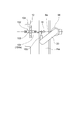
- FIG. 1 is a perspective view of a tip tool according to one embodiment. It is an outline figure showing a bone with peach meat as an example of a bone with limb. It is a top view of the tip tool (open state) concerning one embodiment. It is a top view of the tip tool (closed state) concerning one embodiment. It is a block diagram which shows the control system of the injection
- FIG. 5 is a plan view of a tip tool according to one embodiment.
- FIG. 5 is a front view of a tip tool according to an embodiment. It is an explanatory view showing the grasping state of the bone with flesh by the tip tool concerning one embodiment.
- FIG. 5 is a front view of a tip tool according to an embodiment.
- FIG. 5 is a perspective view of a tip tool (opened state) according to one embodiment. It is a top view of the tip tool (open state) concerning one embodiment. It is a perspective view of the tip tool (closed state) concerning one embodiment. It is a top view of the tip tool (closed state) concerning one embodiment. It is an explanatory view showing grasping operation of a tip tool concerning one embodiment. It is an explanatory view showing the loading operation to the loader part of the input device concerning one embodiment. It is an explanatory view showing the loading operation to the loader part of the input device concerning one embodiment. It is explanatory drawing which shows the loading operation to the loader part of the injection
- expressions that indicate that things such as “identical”, “equal” and “homogeneous” are equal states not only represent strictly equal states, but also have tolerances or differences with which the same function can be obtained. It also represents the existing state.
- expressions representing shapes such as quadrilateral shapes and cylindrical shapes not only represent shapes such as rectangular shapes and cylindrical shapes in a geometrically strict sense, but also uneven portions and chamfers within the range where the same effect can be obtained. The shape including a part etc. shall also be expressed.
- the expressions “comprising”, “having”, “having”, “including” or “having” one component are not exclusive expressions excluding the presence of other components.
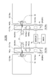
- FIG. 1 and FIG. 2 each show a bone-with-limb injection system 10 (10A, 10B) according to an embodiment.
- the imaging unit 14 (14a, 14b) for imaging the bone-with-limb W (R, L) before being inserted into the processing unit 12 (12a, 12b) and the imaging unit 14
- an image processing unit 16 capable of acquiring posture information of the boned limb W from the image of the boned limb W.
- the distal end tool 17 (17a, 17b) for gripping the boned limb W is supported, and an arm 20 (20a, 20b) capable of controlling the position and posture of the distal end tool 17 is provided.
- the control unit 22 controls the operation of the arm 20 based on the posture information acquired by the image processing unit 16 to hold the limb neck of the bone-in-the-limb W with the tip tool 17 and to the processing unit 12 in a defined direction. Let it go.
- the control unit 22 controls the operation of the arm 20 gripping the boned limb W with the tip tool 17 based on the posture information, thereby processing the plurality of boned limbs in the same direction. It can be put into section 12. As a result, the processing steps for treating a plurality of bones and bones can be uniformly performed in the processing unit 12, so automation of processing such as bone removal can be facilitated in the processing unit 12.
- the boned limb meat W can be aligned in the same direction, the amount of movement of the arm 20 can be suppressed, whereby each of the plurality of processed parts 12 is inserted as in the input system 10 (10A) shown in FIG.
- the processing unit 12 is an automatic bone removing machine, it is possible to cope with the processing speed of the automatic bone removing machine operating at high speed.
- the tip tool 17 can be simplified in structure and can be improved in terms of maintainability and system stoppage due to a failure.
- the tip tool 17 is configured of a pair of clamp pieces that can be opened and closed to each other, and the limb neck portion of the boned limb W is grasped from both sides by the pair of clamp pieces.
- the distal end tool 17 is formed of a hanger having a recess into which the limb neck can be fitted, and the limb neck is fitted and suspended in the recess.
- the processed portion 12 is a processed portion 12 (12a) dedicated to the left limb W (L) and the right. And a processing unit 12 (12b) dedicated to the limb W (R). Also, the input system 10 supplies the left limb exclusive line 10 (10a) for supplying the left limb W (L) to the processing unit 12 (12a) and the right limb W (R) to the processing unit 12 (12b) And a right extremity exclusive line 10 (10b).
- the feeding system 10 may include only one line for both right and left limbs.
- the arm 20 is configured of an arm having a multi-axis articulated joint, and can operate so that the tip tool 17 can be in any position and posture.
- the processing unit 12 is a deboning device that separates the bones and the meat of the boned leg meat W.
- posture information obtained by the image processing unit 16 shown in FIGS. 1 and 2 is front and back information in which the upper surface of the boned limb meat W placed on the grip surface and imaged by the imaging unit 14 is front or back. including.
- the control unit 22 controls the operation of the arm 20 such that the boned limb W is inserted into the processing unit 12 in the direction determined based on the posture information including the front and back surface information.
- the operation of the arm 20 is controlled based on the posture information including the front and back information. It can be introduced into the processing unit 12 so that the front or back surface of the bone with the leg always faces the same direction.
- the conveyor 24 (24 a, 24 b) for transporting the boned limb meat W to the processing unit 12
- the imaging unit 14 includes the boned limb meat W transported by the conveyor 24.
- the imaging unit 14 images the bone-with-limb W conveyed by the conveyor 24, a single imaging unit continuously images a plurality of bone-with-bones to obtain image information. As a result, it is possible to increase the speed at which a plurality of bones and bones are inserted into the processing unit 12 and to improve the processing efficiency of the processing unit 12.
- a plurality of boned limbs W are placed on the conveyor 24 with the front or back side up, and the posture information is the boned limbs imaged by the imaging unit 14 It includes front and back information in which the upper surface of W is the front surface or the back surface.
- the control unit 22 controls the operation of the arm 20 based on posture information including front and back information, and the plurality of boned limbs W are made to the processing unit 12 and either the front or back is always in the same direction with respect to the processing unit 12 Make it turn on.
- the plurality of hangers 26 are attached to the hanger conveyors 28 (28 a, 28 b) and configured to be movable to the processing unit 12.
- the plurality of boned limbs W suspended from the tip tool 17 to the plurality of hangers 26 respectively move to the processing unit 12 and are input to the input unit 32 of the processing unit 12.
- the recess 26 is formed in the hanger 26, and the boned meat W is suspended by inserting a small diameter portion below the neck of the limb into the recess 30.
- the bone-in-the-limb W is a bone-in-bone meat such as a food bird, for example, and the left leg W (L) of the bone-in-bone meat is a line 10 dedicated to the left limb.
- the attitude and the front and back surfaces are randomly placed on the conveyor 24 (24a) of (10a).
- the right leg W (R) of the boned peach meat is randomly placed on the conveyor 24 (24b) of the right-limb dedicated line 10 (10b) in attitude and front and back.
- W (Ls) represents the left leg of the boned peach meat with the surface facing upward
- W (Lb) represents the left leg of the boned peach meat with the back surface facing upward
- W (Ls) Rs) represents the right leg of the boned peach meat with the surface facing upward
- W (Lb) represents the right leg of the boned peach meat with the reverse surface facing upward.
- the control unit 22 controls the operation of the arms 20 (20a, 20b) based on posture information including front and back information, so that a plurality of bones can be detected in each of the lines 10 (10a, 10b).
- the stuffed peach meat can be suspended in order on the plurality of hangers 26 with the front side or the back side always in the same direction.
- a plurality of boned peach meats can be fed in the same direction to the respective processed parts 12 (12a, 12b).
- the plurality of boned peach meats are all hung on the hanger 26 with the knee portion N facing the back side of the pair of clamp pieces 18.
- the plurality of boned peach meat is loaded into the feeding unit 32 in the direction in which the knee portion N faces the loading unit 32 side.
- the boned limb W is obtained. Not only the same direction but also the knee N can be introduced in the same direction. Therefore, since processing in the processing unit 12 can be performed uniformly, automation of the processing unit is easy and processing speed can be increased.
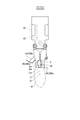
- FIG. 3 shows a tip tool 17 (17c) according to one embodiment.
- the tip tool 17 (17c) is attached to the arm 20 independently of the base 40 supported by the arm 20, the pair of clamp pieces 18 (18a, 18b) attached to the base 40, and the pair of clamp pieces 18 And an attitude adjusting member 34 (34a, 34b).
- the pair of clamp pieces 18 are configured to be openable and closable so as to be able to grip the neck portion of the boned leg meat W.
- the posture adjusting member 34 has inclined surfaces 36 (36a, 36b) which are inclined at an acute angle with respect to the center line C between the pair of clamp pieces in order to adjust the posture of the boned limb W.
- plan view is viewed from a direction (arrow b direction) orthogonal to a plane including the center line C between the pair of clamp pieces and the direction in which the pair of clamp pieces open and close.
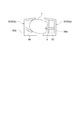
- FIG. 4 shows boned peach meat such as a chicken as an example of the boned leg meat W.
- f is a limb neck that locks onto the hanger when it is suspended by a hanger or the like.
- AA ' is a contact position (maximum diameter portion of the limb neck f) with which the inclined surface 36 contacts, as will be described later
- BB' is a grip position (limb neck) grasped by the pair of clamp pieces 18 The smallest diameter portion below f) is shown.
- Sa shows the cross section of the boned peach meat at the contact position A-A '
- Sb shows the cross section of the boned peach meat at the holding position B-B'.
- the boned limb W has a knee N which is a joint between a femur and a lower femur.
- FIG. 5A shows the state in which the pair of clamp pieces 18 are open
- FIG. 5B shows the state in which it is closed
- FIG. 6 shows a control system of the embodiment shown in FIG. 3 and FIG. 7A to 7C and 8A to 8C show the operation from the state in which the pair of clamp pieces 18 are open to the closing to grasp the boned limb W.
- ⁇ is an acute angle.
- the inclined surface 36 first contacts the boned flesh W.
- the gripping surface for example, the conveying surface of the conveyor 24
- the posture adjustment member 34 when the pair of clamp pieces 18 are in the closed state, the posture adjustment member 34 is a restraint surface existing at a position overlapping the space S in plan view. It has 38.
- FIG. 7A the space S in the second space S 2 which is located away from the first space S 1 and the first space S 1 from the attitude adjustment member 34 located attitude adjustment member 34 side by the center line C It is partitioned, constraining surface 38 in plan view, at the position overlapping the first space S 1.
- the pair of clamp pieces 18 are pivotally supported by the base 40 via the shaft 41, and as shown in FIG. 5A, the opening / closing drive unit built in the base 40 It is opened and closed by 42.
- the posture adjusting member 34 is pivotally supported by the base 40 via a shaft 44 so as to be rotatable in the opening / closing direction of the pair of clamp pieces 18 (the direction of arrow a in FIG. 3).
- the opening and closing drive unit 42 and the rotation drive unit 43 are configured by, for example, an air cylinder.
- the base 40 is attached to the arm 20.
- control unit 22 (22 a) of the present embodiment controls the arm drive unit 21 that drives the arm 20, and controls the open / close drive unit 42 and the rotation drive unit 43.
- the inclined surface 36 of the posture adjustment member 34 is positioned above the pair of clamp pieces 18 when the pair of clamp pieces 18 grip the boned limb W.
- the center of gravity G of the bone-in-the-limb W is located in the meat located below the gripping position of the pair of clamp pieces.
- the inclined surface 36 can be brought into contact with the limb neck f of the boned limb W by positioning the inclined surface 36 above the pair of clamp pieces.
- the control unit 22 controls the rotation drive unit 43 based on the posture information and the front and back information, and when the pair of clamp pieces 18 grip the boned limb W, the center line C
- the posture adjustment member 34 is pivoted so that the inclined surface 36 is located on the same side as the center of gravity G of the boned limb.
- the posture adjusting member 34 can adjust its direction along the opening and closing direction of the pair of clamp pieces 18, when the pair of clamp pieces performs a gripping operation, the inclined surface 36 is a boned limb You can adjust the timing of touching the meat.
- the posture adjustment member 34 includes a mounting portion 46 attached to the base 40, and a pair of extending portions extending in two branches from the mounting portion 46 and having inclined surfaces 36. And 48.
- the control unit 22 (22a) arranges one of the pair of extension portions 48 to be in contact with the boned limb when the upper surface of the boned limb on the grasping surface is the surface, and the upper surface of the boned limb Is the back surface, the other of the pair of extension portions 48 is arranged to be in contact with the flesh with bone.
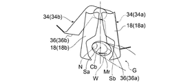
- FIGS. 7A to 7C show that when the boned leg meat W is the right leg of the boned peach meat and the upper surface is the surface, or the boned leg meat W is the left leg of the boned peach meat and the upper surface is the reverse side.
- the operation of the posture adjustment member 34 in the case is shown.
- the inclined surface 36 (36a) of the posture adjustment member 34 (34a) contacts the boned peach meat earlier than the clamp piece 18 (18a).
- the inclined surface 36 (36a) is on the same side as the center of gravity G with respect to the gripping center Cb, and the rotational moment Mr is the center of gravity of the boned peach meat with the inclined surface 36 (36a) as the gripping center of the pair of clamp pieces It is generated to rotate from Cb to the tip side of the clamp piece.
- the boned peach meat is gripped in such a direction that the knee portion N is positioned on the back side of the clamp piece.
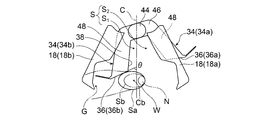
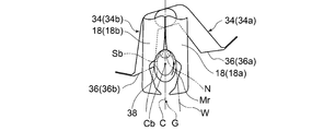
- the inclined surface 36 (36b) of the posture adjustment member 34 (34b) contacts the boned peach meat earlier than the clamp piece 18 (18b).
- the inclined surface 36 (36b) is on the same side as the center of gravity G with respect to the gripping center Cb, and the rotational moment Mr is the center of gravity of the boned limb W with the inclined surface 36 (36b) It is generated so as to rotate from the center Cb to the tip side of the clamp piece.
- the boned peach meat is gripped in such a direction that the knee portion N is positioned on the back side of the clamp piece.
- the knee portion N is always at the back of the clamp piece whether it is the right leg or the left leg or the upper surface is the front or back. It can be held in the same orientation located on the side. Therefore, a plurality of boned limbs W can be input to the processing unit 12 always in the same direction.
- the tip tool 17 (17d) is a boned limb when the boned limb W is gripped by the pair of clamp pieces 19 (19 a, 19 b) for gripping the boned limb W and the pair of clamp pieces 19.
- a rotation suppressing portion 50 (50a, 50b) for suppressing the rotation of the meat W is provided.
- the rotation suppressing portion 50 is provided at a position shifted with respect to the pair of clamp pieces in the direction orthogonal to the plane P including the opening and closing direction of the pair of clamp pieces 18.
- the rotation suppressing portion 50 has a protrusion 52.
- the projection 52 is provided so as to project from the first clamp piece 19 (19a) into the space S between the pair of clamp pieces when viewed from the direction perpendicular to the plane P, and to contact the boned limb W Configured
- the protrusion 52 protrudes toward the boned limb and bites into the boned limb so that the boned limb is attached. Fix the limbs immobile. Since the projection 52 is provided at a position shifted with respect to the pair of clamp pieces 19 in the direction orthogonal to the plane P, the boned limb W can be fixed in cooperation with the pair of clamp pieces 19. Thus, the boned limb W can be stably fixed. In this way, the boned limb W can be introduced to the processing unit 12 in a desired direction by moving the pair of clamp pieces 19 holding the boned limb to a desired position and posture by the arm 20. In addition, by holding the plurality of boned limbs in order with the pair of clamp pieces 19, the directions of the plurality of boned limbs W can be aligned and fed to the processing unit 12.
- the rotation suppressing portion 50 has an abutting portion 54.
- the contact portion 54 is provided on the second clamp piece 19 (19b) side with respect to the projection 52 across the center line C, and is configured to contact the boned limb W. Further, the contact portion 54 extends obliquely with respect to the direction orthogonal to the center line C so as to approach the back side of the pair of clamp pieces as it approaches the first clamp piece 19 (19a).
- the abutment portion 54 cooperates with the rotation suppressing portion 50 to press the boned limb. . Therefore, when the pair of clamp pieces is closed, the projection 52 bites into the bone with the leg from the side of the first clamp piece 19 (19a), and the contact portion 54 forms the bone from the side of the second clamp piece 19 (19b) Since the attached limb can be pressed, the boned limb W can be more stably fixed.
- the protrusion 52 is formed of a plate-like body extending in a direction intersecting the plane P. This can increase the holding power of the protrusion 52 with respect to the boned meat W.
- the boned leg meat W is a boned peach meat such as a chicken
- the boned peach meat has a recess d in the neck portion f along the axial direction. Therefore, when the projection 52 is a plate-like body extending along a direction intersecting with the plane P, the projection 52 can be inserted along the extending direction of the recess d, so that the holding force for the bone with the flesh Can be further improved.
- the abutment portion 54 is formed of a plate-like body extending in a direction intersecting the plane P. Since the area which contact part 54 contacts boned flesh W can be increased by this, the retention power to boned flesh W can be increased.
- the rotation suppressing portion 50 includes a first support wall 56a to which the projection 52 is fixed, and a second support wall 56b to which the contact portion 54 is fixed. And.
- the first support wall 56a and the second support wall 56b extend along a direction intersecting with the plane P, and as shown in FIG. It extends in the direction to widen the distance.
- first support wall 56a and the second support wall 56b in a direction in which the distance between the first support wall 56a and the second support wall 56b increases in the upward direction, It becomes easy to accommodate between the support wall 56a and the second support wall 56b, and the boned limb can be stably suspended by the pair of clamp pieces 18.
- first support wall 56a and the second support wall 56b have a U-shape bent in the direction in which both ends face each other when viewed from the orthogonal direction of the plane P, the strength of these support walls It can improve.
- the rotation suppressing portion 50 is configured of a first rotation suppressing portion 50 (50a) and a second rotation suppressing portion 50 (50b).
- the first rotation suppressing portion includes a first support wall 56a and a projection 52, and is fixed to the first clamp piece 19 (19a).
- the second rotation suppressing portion includes a second support wall 56b and an abutment portion 54, and is fixed to the second clamp piece 19 (19b).
- the first rotation suppressing portion and the second rotation suppressing portion move together with the opening and closing operation of the first clamp piece and the second clamp piece to perform the opening and closing operation, and together with the first clamp piece and the second clamp piece W can be held.
- FIG. 12 and 13 show a tip tool 17 (17e) according to one embodiment.
- the pair of clamp pieces 19 and the rotation suppressing portion 50 are attached to the arm 20 so as to be capable of reversing around the center line C, and by reversing, the first clamp pieces 19 (19 a) and the second The clamp piece 19 (19b), the protrusion 52, and the contact portion 54 are configured to be able to be interchanged with each other at their original positions.
- the control unit 22 (22 b) controls the arm drive unit 21 and the opening / closing drive unit 42 that drive the arm 20 and controls the reverse drive unit 58.
- the positions of the first clamp piece 19 (19a) and the projection 52, and the second clamp piece 19 (19b) and the contact part 54 are selected based on the back surface information.
- the depressions d in the limb neck f are in opposite positions to each other, but the depressions d are in the opposite positions.
- a plurality of boned limbs W are conveyed to arm 20 by conveyor 24 or the like.
- the bone with leg meat is a bone with peach meat and the bone with peach meat is placed randomly on the conveyor, either the upper surface of the bone with peach meat is the front (inner peach surface) or the back (outside peach surface) It is in a state of When the upper surface of the boned peach meat is the front or the back on the holding surface on which the boned peach meat is placed, the depression d in the neck f of the limb is in the reverse position on the surface or the back. According to this embodiment, even when the recess d is in the reverse position, the projection 52 can be applied to the recess d by inverting the pair of clamp pieces 19 and the rotation suppressing portion 50.
- first rotation suppressing portion 50 (50c) and the second rotation suppressing portion 50 (50d) respectively abut on the first support wall 56a having the protrusion 52.
- the second support wall 56 b having the portion 54 is integrally formed.
- First clamp pieces 19 (19a) are respectively provided at upper and lower ends of the first rotation restraining portion 50 (50c), and second clamp pieces 19 (19b) at upper and lower ends of the second rotation restraining portion 50 (50d). Is provided.
- the pair of clamp pieces 19 and the rotation suppressing portion 50 are configured to be capable of reversing 180 degrees around the center point O with respect to the base 40, and by reversing 180 degrees, the first clamp piece 19 (19a) and the second clamp The piece 19 (19b), the protrusion 52, and the contact portion 54 are configured to be able to be interchanged with each other in their original positions.
- the center point O is located at a position overlapping the center line C as viewed in a direction perpendicular to the plane P, and is located at the boundary between the first support wall 56a and the second support wall 56b.
- the first rotation suppressing portion 50 (50c) is fixed to the first clamp piece 19 (19a)
- the second rotation suppressing portion 50 (50d) is fixed to the second clamp piece 19 (19b).
- the bone-with-limb W is suspended on a pair of lower clamp pieces 19 (19a, 19b).
- the projection 52 of the first rotation suppression unit 50 (50c) can be disposed at the position where the projection 52 of the second rotation suppression unit 50 (50d) was located by reversing it 180 degrees.
- the contact portion 54 of the first rotation suppression portion can be disposed at the position where the contact portion 54 of the second rotation suppression portion was located by being inverted 180 degrees. Therefore, even if the recess d is in the reverse position on the front and back, the projection 52 can be applied to the recess d by reversing the clamp piece 19 and the rotation suppressing portion 50.
- the first support wall 56a and the second support wall 56b of the first rotation suppressing portion 50 (50c) and the second rotation suppressing portion 50 (50d) have a center point O. It extends in the direction to narrow the distance from each other as it gets away from the
- the boned limb W is a region of the first support wall 56a and the second support wall 56b located below the boned limb W in the hanging direction of the first and second rotation restraints.
- the first support wall and the second support wall which are gripped by the bone and the boned limb are gripped, extend in a direction to extend the distance from each other upward in the hanging direction of the boned limb W, so the gripping position As compared with BB ', it is easier to accommodate the largest diameter portion of the limb neck f with a larger diameter between the first and second support walls, thereby stabilizing the boned limb flesh It can be suspended.
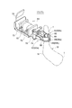
- FIGS. 14-17 illustrate a tip tool 17 (17f) according to one embodiment.
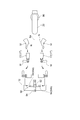
- FIGS. 14 and 15 show the pair of clamp pieces 62 (62a, 62b) in the open state
- FIGS. 16 and 17 show the pair of clamp pieces 62 (62a, 62b) in the closed state capable of grasping the boned limb W.
- the boned leg meat W shown in FIG. 16 simulates the contour of the boned peach meat of a food bird.
- the small diameter portion between the enlarged diameter portion of the limb neck f and the peach portion t is the gripping portion by the pair of clamp pieces 62.
- the tip tool 17 (17f) includes a pair of clamp pieces 62, and a support portion 64 that supports the pair of clamp pieces 62 at the base of the pair of clamp pieces 62 so as to be opened and closed. And a rotation suppressing portion 66 capable of suppressing the rotation and wobbling of the boned limb W when held by the piece 62.
- the rotation suppressing portion 66 protrudes from the surface of each clamp piece 62 (62a, 62b) along a direction orthogonal to the plane P including the opening / closing direction of the pair of clamp pieces 62 (the arrow direction in FIG. 2). Provided as.
- the tip portions 68 (68a, 68b) of the clamp pieces are located in a position closer to the center line C between the pair of clamp pieces than the rotation suppressing part 66 in the open state, and turn in the direction along the center line C. It is located at a position farther from the support portion 64 than the movement suppression portion 66, that is, at the tip end side.
- the rotation suppressing portion 66 can suppress rotation and wobble of the bone-with-limb meat W and fix it at the clamp position. Further, since the tip end portion 68 of the clamp piece 62 is on the inner side (center line C side) and the tip end side than the rotation suppressing portion 66, the tip end portion 68 of the clamp piece 62 W is inserted under the clamp site (limb neck f) of the bone-in-the-limb W, and the clamp site is scooped up. By this operation, it is possible to securely grasp the boned limb with the pair of clamp pieces 62. Further, since stable gripping is possible, the operation of the clamp piece 62 can be accelerated.
- the boned limb W is obtained. It can be suspended on the hanger 26 in a desired orientation, or can be introduced into the processing unit 12 such as a bone removing device via the hanger 26.
- the support 64 includes an actuator 70 for opening and closing the pair of clamp pieces 62.
- the actuator 70 is constituted by a hydraulic cylinder provided with a hydraulic oil inlet / outlet 72, and reciprocates the shaft 74 in the direction along the center line C.
- the pair of clamp pieces 62 is rotatably supported by the shaft 76, and the shaft 76 is pivoted by the reciprocating motion of the shaft 74, and the pair of clamp pieces 62 is opened and closed.
- a mounting plate 78 is provided on the back side of the support portion 64, and the support portion 64 is mounted to the multi-axial articulated arm 20 capable of controlling the position and posture of the support portion 64 via the mounting plate 78.
- the rotation suppressing portion 66 is provided on each of the pair of clamp pieces 62 (62a, 62b), and each rotation suppressing portion 66 has a contact piece 80 extending toward the center line C side. As shown in FIGS. 16 and 17, the contact piece 80 is configured to contact the gripped boned flesh W when the pair of clamp pieces 62 are in the closed state. According to this embodiment, when the boned limb W is gripped by the pair of clamp pieces 62, the boned limb W can be fixed by the contact piece 80, so that the rotational wiggle of the boned limb W can be prevented. .
- the contact piece 80 is formed of a plate-like body extending in a direction intersecting the opening / closing direction plane. Since the contact piece 80 extends along the longitudinal direction of the griped limb neck, it can be more firmly fixed to the clamp piece.
- FIG. 17 shows a state in which the limb neck f of a boned peach meat of a food such as a chicken is gripped by a pair of clamp pieces 62 as the boned limb W.
- the boned leg meat W is a boned peach meat of a food bird, a recess d is present in the neck portion f in the longitudinal direction.
- the contact piece 80 is a plate-like body extending along a direction (a direction perpendicular to the drawing in the drawing) intersecting the opening / closing direction plane, one side of the contact piece 80 is inserted into the recess d. Can be further improved.
- the rotation suppressing portion 66 is configured to include the wall portion 82 (82a, 82b, 82c).
- the wall portions 82 are respectively provided on the pair of clamp pieces 62 so as to face each other across the space S between the pair of clamp pieces 62.
- the tip portions 68 (68a, 68b) of the clamp pieces 62 (62a, 62b) are located inside (closer to the center line C) than the wall 82 in the open state and in the direction along the center line C It is located farther from the support 64 than the wall 82 (tip side).
- the strength of the clamp piece 62 can be enhanced by the presence of the wall portion 82, and the wall portion 82 is in the above-described positional relationship with the tip portion 68 of the clamp piece 62.
- the rotation suppressing portion 66 can support the boned limb W that has been raised by the tip portion 68. By this, it is possible to grip the boned leg meat W with certainty.
- the wall 82 extends along at least a portion of the contour of each clamp piece 62 (62a, 62b) away from the center line C, so that the wall of the clamping operation of the clamp piece 62 may be disturbed.
- the movement of the clamp piece 62 can be assisted to prevent the boned human flesh W from coming off the clamp piece 62.
- the wall 82 constituting the rotation suppressing part 66 is configured by the first wall 82 (82a), the second wall 82 (82b), and the third wall 82 (82c).
- the first wall 82 (82 a) extends along the center line C in the closed state of the pair of clamp pieces 62.
- the second wall 82 (82b) is connected to the end of the first wall 82 (82a) on the support 64 side, and extends from the first wall 82 (82a) by bending toward the center line C .
- the third wall 82 (82c) is connected to the end of the first wall 82 (82a) on the opposite side to the support 64 and is bent from the first wall 82 (82a) toward the center line C To extend.
- the contact piece 80 is disposed between the second wall 82 (82b) and the third wall 82 (82c).
- the first wall 82 (82a), the second wall 82 (82b) and the third wall 82 (82c) surround the boned limb W grasped by the clamp piece 62. Since it is disposed, the boned limb W, which is picked up by the tip 68 of the clamp piece 62 at the initial stage of the gripping operation, is moved to the first wall 82 (82a), the second wall 82 (82b) and the third wall 82 ( At 82c), the boned flesh W can be prevented from coming off the tip 68, and the rotation and wobble of the griped boned flesh W can be suppressed.
- the second wall 82 (82 b) and the third wall 82 (82 c) are inclined relative to the center line C in the closed state of the pair of clamp pieces 62, and third wall portion 82 an inclination angle alpha 3 relative to the center line C of (82c) the inclination angle alpha 2 smaller relative to the center line C of the second wall portion 82 (82b) ( ⁇ 3 ⁇ ⁇ 2).
- the third wall 82 (82c) can be approached to the gripping surface.
- the third wall 82 (82 c) can be inserted below the boned limb W picked up by the distal end 68 of the clamp piece 62, and the boned limb W can be prevented from coming off from the distal end 68. By this, it is possible to grip the boned leg meat W with certainty.
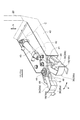
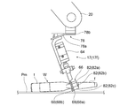
- FIG. 18 shows a scene in which the bone-with-limb W placed on the gripping surface Pm is gripped and transferred by the end tool 17 (17f).
- the distal end tool 17 (17f) is attached to the arm 20 via the attachment plate 78.
- the arm 20 is configured by a multi-axis articulated joint, and can control the position and attitude of the tip tool 17 (17 f).
- the clamp device side mounting portion 78a of the mounting plate 78 is inclined at an angle ⁇ with respect to the arm side mounting portion 78b. For this reason, the clamp piece 62 is inclined at an angle ⁇ with respect to the gripping surface Pm, and this inclination facilitates the approaching operation of the clamp device 10 with respect to the boned flesh W.
- the tip portions 68 (68a, 68b) of the clamp pieces 62 are configured to overlap one another when viewed from the direction orthogonal to the plane P in the closed state.
- the tip portions of the clamp pieces 62 can be closed before the pair of clamp pieces 62 are closed, it is possible to prevent the drop of the boned limb W from the tip side of the clamp pieces.
- the pair of tip portions 68 (68 a, 68 b) are arranged to be shifted in the direction orthogonal to the plane P. This allows the tips 68 (68a, 68b) to overlap one another.
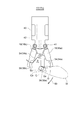
- a loader unit 90 is provided for receiving the bone-with-limb W from the tip tool 17 (17f) and delivering it to the processing unit 12 side.
- the loader unit 90 includes a pivot shaft 92 and three or more hangers 94 which are pivotable about the pivot shaft 92 and arranged at equal angular intervals with respect to the pivot shaft 92. .
- suspension is performed based on the posture information of the boned limb W obtained by the image processing unit 16.
- the hanger 94 the operation of the arm 20 and the tip tool 17 (17f) can be simplified.
- the suspension speed to the hanger 94 can be increased, or the injection speed of the bone-with-limb W to be injected into the processing unit 12 can be increased.
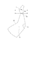
- the arm 20 and the tip tool 17 (17f) are controlled by the control unit 22 when the boned limb W is suspended from the gripping surface Pm to the hanger 94 by the tip tool 17 (17f). Indicates the operation.
- FIG. 21 shows operations of the arm 20 and the tip tool 17 (17f) as a comparative example.
- the control unit 22 rotates the rotation shaft 92 and the arm 20 when the upper surface of the boned limb W determined by the image processing unit 16 is a surface.
- the boned limb W is suspended from the end tool 17 (17f) to the hanger 94 on one side with respect to a reference line Ba connecting the pedestal 96 which supports it, and the boned limb W determined by the image processing unit 16
- the upper surface is the back surface, it is configured to control the boned limb W to be suspended from the tip tool 17 (17f) to the hanger 94 on the other side with respect to the reference line Ba.
- three hangers 94 are attached to the pivot shaft 92 at equal angular intervals of 120 degrees, and in the embodiment shown in FIG. 20, four hangers 94 at equal angular intervals of 90 degrees.
- the rotary shaft 92 is attached.
- the tip tool 17 (17f) grips the boned limb W and suspends on the hanger 94 (94a), and the upper surface of the boned limb W has a back surface
- the tip tool 17 (17f) grips the boned limb W and suspends it on the hanger 94 (94b).
- the operation of the arm 20 and the tip tool 17 (17f) can be simplified, so that the suspension speed to the hanger 94 or the input speed to the processing unit 12 can be increased. That is, it is possible to suspend on the hanger 94 without largely changing the angle of the arm 20 with respect to the reference line Ba and the angle of the clamp piece 62 with respect to the arm 20.
- the boned flesh W has a different orientation of the knee N when the upper surface is the front or back surface. The difference in the direction of the knee N can be offset by suspending the bone-with-limb W on the hanger 94 at different positions with respect to the reference line Ba, and the movement of the arm 20 and the tip tool 17 (17f) can be simplified. .
- the tip tool 17 (17f) can be suspended on the hanger 94 simply by tilting it 30 degrees with respect to the reference line Ba.
- the tip tool 17 (17f) can be suspended on the hanger 94 only by inclining it by 90 degrees with respect to the reference line Ba.
- the tip tool 17 (17f) may be rotated by 120 degrees in FIG. 19 or 90 degrees in FIG.
- the rotation time of 94 can be shortened. Therefore, the suspension speed and the input speed can be increased, and the throughput can be increased.
- the rotating shaft 103 of the loader portion 102 is disposed on the reference line Ba, and for example, two or four hangers 104 are provided at equal angles on the rotating shaft 103. ing.
- the boned flesh W on the gripping surface Pm (for example, the conveyor conveyance surface) is always located in front of the reference line Ba regardless of whether the upper surface of the boned flesh W is the front or back by the tip tool 100 It is suspended by the hanger 104 (104a). At this time, as shown in the figure, it is necessary to largely change the angle of the arm 20 with respect to the reference line Ba and the angle of the tip tool 100 with respect to the arm 20.
- each hanger 104 when the suspended boned limb W is inserted into the processing unit 12, it is necessary to rotate the hanger 104 by 180 degrees. Therefore, there is a problem that the suspension speed and the injection speed per bone and limb can be increased as compared with the above embodiment.
- the loader unit 90 is provided between the tip end tool 17 (17f) and the processing unit 12, but instead of the processing unit 12, a plurality of hangers 26 may be provided as shown in FIG.
- the hanger conveyor 28 may be provided, and the loader unit 90 may be used to transfer the boned leg meat W from the tip tool 17 to the plurality of hangers 26.
- the bone-with-limb W is not limited to food birds, but includes all bone-with-bones legs such as legs, arms and the like of domestic animals such as pigs, cows and sheep.
- the operation of aligning and injecting the directions of a plurality of bone-in-bones can be automated by a machine without manual operation.
Abstract
Description
特許文献1には、骨付きモモ肉の脱骨処理を行う自動脱骨装置が開示されている。この装置は、骨付きモモ肉をクランプ装置に吊架しながら複数の処理ステーション間を断続搬送し、各ステーションで骨付きモモ肉の筋入れや骨肉分離等のステップを順々に行うことで、自動脱骨を可能にしている。
特許文献2には、コンベアで搬送される骨付きモモ肉を多軸多関節アームで把持してハンガに吊架させるクランプ装置が開示されている。 In order to save labor, the processing of food birds and animals is being carried out by manual processing and automated processing by machines.
Patent Document 1 discloses an automatic bone removing apparatus for removing bones from peach meat with bones. This device intermittently transports between a plurality of processing stations while suspending boned peach meat on a clamp device, and sequentially performs steps such as scoring of boned peach meat and separation of bone meat at each station. It enables automatic bone removal.
特許文献1及び2には、自動脱骨装置などに複数の骨付き肢肉の向きを揃えて投入する作業を自動化する手段は開示されていない。 When boned limbs such as boned peach meat are introduced into the automatic bone removing apparatus, the directions of the plurality of boned limbs should be aligned so that processing steps can be uniformly performed on the plurality of boned limbs. It is necessary to introduce it. However, under the present circumstances, it is difficult to automate the operation of aligning and feeding the directions of a plurality of bones and limbs with a machine, and it is necessary to have assistant personnel to perform this operation.
骨付き肢肉を加工部に投入するための投入システムであって、
前記加工部に投入する前の前記骨付き肢肉を撮像するための撮像部と、
前記撮像部で撮像した前記骨付き肢肉の画像から前記骨付き肢肉の姿勢情報を取得可能な画像処理部と、
前記骨付き肢肉を把持するための先端ツールと、
前記先端ツールを支持し、前記先端ツールの位置及び姿勢を制御可能なアームと、
前記画像処理部が取得した前記姿勢情報に基き、少なくとも前記アームの動作を制御して前記骨付き肢肉の肢首部を把持し、定められた向きで前記加工部に投入させる制御部と、
を備える。 (1) A system for feeding bones and legs according to one embodiment:
An injection system for inserting a boned limb into a processing unit,
An imaging unit for imaging the bone-with-limb prior to insertion into the processing unit;
An image processing unit capable of acquiring posture information of the bone-with-limb from the image of the bone-with-limb imaged by the imaging unit;
A tip tool for grasping the boned limb meat;
An arm supporting the tip tool and capable of controlling the position and attitude of the tip tool;
A control unit configured to control the operation of at least the arm based on the posture information acquired by the image processing unit to grip the neck of the limb with the bone, and to inject it into the processing unit in a predetermined direction;
Equipped with
前記姿勢情報は、前記撮像部で撮像した骨付き肢肉の上面が表面又は裏面である表裏面情報を含み、
前記制御部は、前記表裏面情報を含む前記姿勢情報に基づいて前記加工部に前記骨付き肢肉を投入するように少なくとも前記アームの動作を制御するように構成される。
先端ツールで骨付き肢肉の肢首部を把持するとき、骨付き肢肉は例えばコンベアの搬送面などに置かれている。このとき骨付き肢肉が置かれている面を、便宜上本明細書では「把持面」とも言う。骨付き肢肉において、例えば食鳥などの骨付きモモ肉では、内モモ面が表面であり、外モモ面が裏面となる。 (2) In one embodiment, in the configuration of (1),
The posture information includes front and back information in which the upper surface of the boned limb flesh imaged by the imaging unit is the front surface or the back surface,
The control unit is configured to control at least an operation of the arm so as to insert the bone-with-limb in the processing unit based on the posture information including the front and back surface information.
When grasping the limb neck of the boned limb with the tip tool, the boned limb is placed, for example, on the conveying surface of the conveyor. At this time, the surface on which the bone-in-limb is placed is also referred to as a “gripping surface” in the present specification for convenience. In the bone-in-carcass meat, for example, in a bone-in-bone meat such as a food bird, the inner peach surface is the surface and the outer peach surface is the back surface.
前記骨付き肢肉を前記加工部まで搬送するコンベアを備え、
前記撮像部は、前記コンベアで搬送される前記骨付き肢肉を撮像するように構成される。
上記(3)の構成によれば、撮像部は上記コンベアで搬送される骨付き肢肉を撮像するので、1個の撮像部で複数の骨付き肢肉を連続的に撮像して画像情報を得ることで、複数の骨付き肢肉の加工部への投入速度を高めることができ、これによって、加工部の処理効率を向上できる。 (3) In one embodiment, in the configuration of (1) or (2),
A conveyor for conveying the boned limb to the processing unit;
The imaging unit is configured to image the bone-in-the-bone flesh transported by the conveyor.
According to the configuration of the above (3), since the imaging unit images the boned limb transported by the conveyor, a single imaging unit continuously images a plurality of boned limbs to obtain image information. As a result, it is possible to increase the speed at which a plurality of bones and legs are inserted into the processing unit, and thereby the processing efficiency of the processing unit can be improved.
複数の前記骨付き肢肉が前記コンベアに表面又は裏面を上にして置かれ、
前記姿勢情報は、前記撮像部で撮像した前記骨付き肢肉の上面が表面又は裏面である表裏面情報を含み、
前記制御部は、前記表裏面情報を含む前記姿勢情報に基づいて前記アームの動作を制御し、前記複数の骨付き肢肉を前記加工部に表面又は裏面のどちらかが常に前記加工部に対し同一方向を向くように投入するように構成される。
上記構成によれば、コンベアに複数の骨付き肢肉の姿勢及び表裏面の向きがランダムに置かれていても、複数の骨付き肢肉を表面又は裏面のどちらかが常に同一の方向を向くように高効率で加工部に投入できる。 In one embodiment, in the configuration of (3),
A plurality of the boned limbs are placed on the conveyor with the front or back side up,
The posture information includes front and back information in which the upper surface of the bone-with-limb flesh imaged by the imaging unit is the front or back,
The control unit controls the operation of the arm based on the posture information including the front and back information, and the plurality of bones and bones are attached to the processing unit and either the front or back is always to the processing unit. It is configured to feed in the same direction.
According to the above configuration, even if the postures of the plurality of boned limbs and the orientation of the front and back are randomly placed on the conveyor, either the front or the back always faces the same direction for the plurality of boned limbs It can be put into the processing part with high efficiency.
前記骨付き肢肉を吊架可能であって該骨付き肢肉を前記加工部まで搬送可能な複数のハンガを備え、
前記制御部は、前記アームの動作を制御し、前記複数のハンガの各々に前記複数の骨付き肢肉を表面又は裏面のどちらかが常に同一方向を向くように吊架するように構成される。
上記構成によれば、複数のハンガに骨付き肢肉を表面又は裏面のどちらかが常に同一方向を向くように吊架できるので、該ハンガを介して複数の骨付き肢肉を加工部に表面又は裏面のどちらかが常に同一方向を向くように投入できる。 In one embodiment, in the configuration,
The apparatus further comprises a plurality of hangers that can suspend the boned limb and transport the boned limb to the processing unit.
The control unit is configured to control the movement of the arm and to suspend the plurality of boned limbs on each of the plurality of hangers such that either the front or the back always faces in the same direction. .
According to the above configuration, since it is possible to suspend the boned limb on the plurality of hangers so that either the front or the back always faces the same direction, the plurality of boned limbs are surfaced on the processing portion through the hangers. Or it can be injected so that either of the back side always points in the same direction.
前記骨付き肢肉のうち右肢または左肢のどちらか一方のみを前記加工部に投入する。
上記(4)の構成によれば、右肢又は左肢のどちらか一方のみを加工部に投入することで、骨付き肢肉を加工部に投入したとき、ひざ部も同じ向きで投入できる。従って、加工部での処理を一律に行うことができるので、自動化が容易であると共に、処理スピードを上げることができる。 (4) In one embodiment, in any one of the configurations (1) to (3),
Only one of the right and left limbs of the boned limb is introduced into the processing unit.
According to the configuration of the above (4), by inserting only one of the right and left limbs into the processing portion, when the bone-with-limb is inserted into the processing portion, the knee portion can also be loaded in the same direction. Therefore, since processing in the processing unit can be uniformly performed, automation is easy and processing speed can be increased.
前記先端ツールから前記骨付き肢肉を受領して前記加工部側へ渡すためのローダ部を備え、
前記ローダ部は、回動軸と、該回動軸を中心に回動可能であって、前記回動軸に対して等角度間隔で配置された3個以上のハンガと、を備える。
上記(5)の構成によれば、骨付き肢肉を先端ツールからローダ部のハンガに懸架するとき、撮像部で得られる骨付き肢肉の姿勢情報に基づいて懸架するハンガを選択することで、アーム及び先端ツールの操作を簡素化できる。これによって、懸架速度を増加でき、あるいは加工部への搬送量を増加できる。 (5) In one embodiment, in any one of the configurations (1) to (4),
And a loader unit for receiving the flesh with bones from the tip tool and delivering it to the processing unit side,
The loader portion includes a pivoting axis, and three or more hangers which are pivotable about the pivoting axis and arranged at equal angular intervals with respect to the pivoting axis.
According to the configuration of (5), when suspending the boned limb from the tip tool to the hanger of the loader unit, by selecting the hanger to be suspended based on the posture information of the boned limb obtained by the imaging unit , The operation of the arm and the tip tool can be simplified. As a result, the suspension speed can be increased, or the transport amount to the processing unit can be increased.
前記制御部は、前記撮像部で撮像した前記骨付き肢肉の上面が表面であるとき、前記回動軸と前記アームを移動可能に支持する台座とを結ぶ基準線に対して一方側で前記骨付き肢肉を前記先端ツールから前記ハンガに懸架し、前記撮像部で撮像した前記骨付き肢肉の上面が裏面であるとき、前記基準線に対して他方側で前記骨付き肢肉を前記先端ツールから前記ハンガに懸架するように制御するように構成される。
上記(6)の構成によれば、骨付き肢肉の上面が表面であるときと裏面であるときとで、上記基準線を境とする異なる位置で骨付き肢肉をハンガに懸架することで、アーム及び先端ツールの操作を簡素化できる。これによって、ハンガへの懸架速度あるいは加工部への搬送量を増加できる。 (6) In one embodiment, in the configuration of (5),
When the upper surface of the bone-with-limb flesh imaged by the imaging unit is a surface, the control unit may perform, on one side with respect to a reference line connecting the pivot shaft and a pedestal that movably supports the arm. The boned limb is suspended from the tip tool to the hanger, and the upper surface of the boned limb imaged by the imaging unit is the back surface, the boned limb on the other side with respect to the reference line It is configured to control suspension from the tip tool to the hanger.
According to the configuration of (6), the boned limb is suspended on the hanger at different positions bordering on the reference line when the upper surface of the boned limb is the front and the back. , The operation of the arm and the tip tool can be simplified. By this, the suspension speed to a hanger or the conveyance amount to a process part can be increased.
前記先端ツールは、
前記アームに支持される基部と、
前記基部に取り付けられ、骨付き肉を把持するように構成された一対のクランプ片と、
前記一対のクランプ片とは独立して前記基部に取り付けられ、前記一対のクランプ片間の中心線に対して鋭角に傾斜する傾斜面を有し、前記骨付き肉の姿勢を調整するための姿勢調整部材と、
を含み、
前記一対のクランプ片が開状態のとき、平面視において、前記姿勢調整部材の前記傾斜面の少なくとも一部が前記一対のクランプ片間に形成される空間に重なるように配置される。
なお、本明細書において、「平面視」とは、上記一対のクランプ片間の中心線及び一対のクランプ片が開閉する方向を含む平面に対して直交する方向から視ることを言う。 (7) In one embodiment, in any one of the configurations (1) to (6),
The tip tool is
A base supported by the arm;
A pair of clamp pieces attached to the base and configured to grip boned meat;
It has an inclined surface attached to the base independently from the pair of clamp pieces and inclined at an acute angle with respect to the center line between the pair of clamp pieces, and an attitude for adjusting the posture of the bone with meat An adjustment member,
Including
When the pair of clamp pieces are in the open state, at least a part of the inclined surface of the posture adjustment member is arranged to overlap a space formed between the pair of clamp pieces in plan view.
In addition, in this specification, "a planar view" means seeing from a direction orthogonal to the plane including the center line between the pair of clamp pieces and the direction in which the pair of clamp pieces open and close.
一対のクランプ片が骨付き肢肉を把持して骨付き肢肉の一部を持ち上げた時、骨付き肢肉の把持部位の中心と骨付き肢肉の重心との間に平面視で位置ずれが起こる。 In the configuration of (7), when the pair of clamp pieces are in the closed state, at least a part of the inclined surface of the posture adjustment member is arranged to overlap the space formed between the pair of clamp pieces in plan view As a result, when the pair of clamp pieces begin to close, the inclined surface of the posture adjustment member makes contact with the flesh with bones first.
When a pair of clamp pieces grip the boned limb meat and lift up a part of the boned limb meat, the positional deviation in plan view between the center of the gripped part of the boned limb meat and the center of gravity of the boned limb meat Happens.
前記先端ツールは、
第1クランプ片及び第2クランプ片を含み、骨付き肉を把持するように開閉可能な一対のクランプ片と、
前記一対のクランプ片の開閉方向を含む平面に対して直交する方向において前記一対のクランプ片に対してずれた位置に設けられ、前記骨付き肉の回動を抑制するための回動抑制部と、
を含み、
前記回動抑制部は、前記平面の直交方向から視たとき、前記第1クランプ片から前記一対のクランプ片間の空間内に突出するように設けられ、前記骨付き肉に接触するように構成された突起部を含む。 (8) In one embodiment, in any one of the configurations (1) to (6),
The tip tool is
A pair of clamp pieces including a first clamp piece and a second clamp piece, which can be opened and closed so as to grip boned meat;
A rotation suppressing portion provided at a position shifted with respect to the pair of clamp pieces in a direction orthogonal to a plane including the opening and closing direction of the pair of clamp pieces, for suppressing rotation of the boned meat ,
Including
The rotation suppressing portion is provided so as to protrude from the first clamp piece into the space between the pair of clamp pieces when viewed in a direction perpendicular to the plane, and configured to contact the boned meat. Including the protruding portion.
こうして骨付き肢肉を把持した一対のクランプ片を所望の位置及び姿勢に動作させることで、骨付き肢肉を加工部に所望の向きで投入でき、一対のクランプ片で複数の骨付き肢肉を順々に把持することで、複数の骨付き肢肉の向きを揃えて加工部に投入できる。 According to the configuration of the above (8), when the pair of clamp pieces is closed to grip the boned limb, the projection projects toward the boned limb and bites into the boned limb. It can fix bones and limbs so as not to move. The projection is provided at a position offset with respect to the pair of clamp pieces in a direction orthogonal to a plane including the opening and closing direction of the pair of clamp pieces, so that the boned limb meat in cooperation with the pair of clamp pieces It is possible to fix bones and limbs stably by this.
In this way, by moving the pair of clamp pieces holding the boned limb to the desired position and posture, the boned limb can be introduced into the processing section in the desired direction, and a plurality of boned limbs can be inserted by the pair of clamp pieces. By grasping in sequence, it is possible to align the directions of the plurality of bones and limbs with one another and to feed them into the processing unit.
前記先端ツールは、
骨付き肉を把持するための一対のクランプ片と、
各々の前記クランプ片の基部において前記一対のクランプ片を開閉可能に支持する支持部と、
前記一対のクランプ片の開閉方向を含む平面に対して直交する方向に沿って前記一対のクランプ片の表面から突出するように設けられ、前記骨付き肉の回動を抑制するための回動抑制部と、
を含み、
前記一対のクランプ片の各々は、前記一対のクランプ片の開状態において、前記回動抑制部より前記一対のクランプ片間の中心線寄りの位置であって、かつ、前記中心線に沿った方向において前記回動抑制部よりも前記支持部から遠い位置に先端部を有する。 (9) In one embodiment, in any one of the configurations (1) to (6),
The tip tool is
A pair of clamp pieces for gripping boned meat,
A support that supports the pair of clamp pieces openably and closably at the base of each of the clamp pieces;
It is provided so as to project from the surface of the pair of clamp pieces along a direction orthogonal to a plane including the opening and closing direction of the pair of clamp pieces, and rotation suppression for suppressing rotation of the boned meat Department,
Including
Each of the pair of clamp pieces is a position closer to the center line between the pair of clamp pieces than the rotation suppressing portion in the open state of the pair of clamp pieces, and a direction along the center line And a tip end portion at a position farther from the support portion than the rotation suppression portion.
さらに、上記支持部を位置制御及び姿勢制御可能なアームに取り付け、骨付き肢肉を把持したクランプ装置を所望の位置及び姿勢に制御することで、骨付き肢肉を所望の向きでハンガに懸架でき、あるいは該ハンガを介して脱骨装置などの加工部に投入できる。 According to the configuration of the above (9), when the boned limb is gripped by the pair of clamp pieces, the rotation suppressing portion can suppress rotation and wobble of the boned limb and fix it at the clamp position. In addition, since the tip end of the clamp piece is on the inner side (the center line side) and the tip end side (the side farther from the support portion) than the rotation suppressing portion, the tip end of the clamp piece It is inserted under the boned limb with the attached limb and scoops up the boned limb. By this operation, it is possible to reliably grasp the boned limb with a pair of clamp pieces. In addition, since stable gripping is possible, the operation of the clamp piece can be accelerated.
Furthermore, the above-mentioned support portion is attached to the position-controllable and attitude-controllable arm, and the clamp device holding the boned limb is controlled to a desired position and posture, thereby suspending the boned limb in the desired direction on the hanger. Or can be introduced into a processing unit such as a deboning device via the hanger.
例えば、「ある方向に」、「ある方向に沿って」、「平行」、「直交」、「中心」、「同心」或いは「同軸」等の相対的或いは絶対的な配置を表す表現は、厳密にそのような配置を表すのみならず、公差、若しくは、同じ機能が得られる程度の角度や距離をもって相対的に変位している状態も表すものとする。
例えば、「同一」、「等しい」及び「均質」等の物事が等しい状態であることを表す表現は、厳密に等しい状態を表すのみならず、公差、若しくは、同じ機能が得られる程度の差が存在している状態も表すものとする。
例えば、四角形状や円筒形状等の形状を表す表現は、幾何学的に厳密な意味での四角形状や円筒形状等の形状を表すのみならず、同じ効果が得られる範囲で、凹凸部や面取り部等を含む形状も表すものとする。
一方、一つの構成要素を「備える」、「具える」、「具備する」、「含む」、又は「有する」という表現は、他の構成要素の存在を除外する排他的な表現ではない。 Hereinafter, some embodiments of the present invention will be described with reference to the accompanying drawings. However, the dimensions, materials, shapes, relative arrangements and the like of the components described as the embodiments or shown in the drawings are not intended to limit the scope of the present invention to these, but are merely illustrative examples.
For example, a representation representing a relative or absolute arrangement such as “in a direction”, “along a direction”, “parallel”, “orthogonal”, “center”, “concentric” or “coaxial” is strictly Not only does it represent such an arrangement, but also represents a state of relative displacement with an angle or distance that allows the same function to be obtained.
For example, expressions that indicate that things such as "identical", "equal" and "homogeneous" are equal states not only represent strictly equal states, but also have tolerances or differences with which the same function can be obtained. It also represents the existing state.
For example, expressions representing shapes such as quadrilateral shapes and cylindrical shapes not only represent shapes such as rectangular shapes and cylindrical shapes in a geometrically strict sense, but also uneven portions and chamfers within the range where the same effect can be obtained. The shape including a part etc. shall also be expressed.
On the other hand, the expressions "comprising", "having", "having", "including" or "having" one component are not exclusive expressions excluding the presence of other components.
図1及び図2において、加工部12(12a、12b)に投入する前の骨付き肢肉W(R、L)を撮像するための撮像部14(14a、14b)と、撮像部14で撮像された骨付き肢肉Wの画像から骨付き肢肉Wの姿勢情報を取得可能な画像処理部16とを備える。
また、骨付き肢肉Wを把持するための先端ツール17(17a、17b)を支持し、先端ツール17の位置及び姿勢を制御可能なアーム20(20a、20b)を備える。制御部22は、画像処理部16が取得した姿勢情報に基き、アーム20の動作を制御して先端ツール17で骨付き肢肉Wの肢首部を把持し、定められた向きで加工部12に投入させる。 FIG. 1 and FIG. 2 each show a bone-with-limb injection system 10 (10A, 10B) according to an embodiment.
In FIG. 1 and FIG. 2, the imaging unit 14 (14a, 14b) for imaging the bone-with-limb W (R, L) before being inserted into the processing unit 12 (12a, 12b) and the
Further, the distal end tool 17 (17a, 17b) for gripping the boned limb W is supported, and an arm 20 (20a, 20b) capable of controlling the position and posture of the
また、図2に示す投入システム10(10B)のように、1個の加工部12に対して1台のアーム20を使用する投入システム10(10B)の場合は、アーム20の移動量を抑制する必要は無く、また高速の動作も求められないため、先端ツール17は構造をシンプルにする事が可能になり、メンテナンス性や故障によるシステム停止を改善することが可能になる。 In addition, since the boned limb meat W can be aligned in the same direction, the amount of movement of the
Further, in the case of a loading system 10 (10B) using one
一実施形態では、先端ツール17は、肢首部が嵌合可能な凹部を有するハンガで構成され、該凹部に肢首部を嵌合させ吊架する。 In one embodiment, the
In one embodiment, the
この実施形態のように、骨付き肢肉Wのうち右肢または左肢のどちらか一方のみを加工部12に投入することで、骨付き肢肉Wを同じ向きだけでなく、ひざ部Nも同じ向きで投入できる。従って、加工部12での処理を一律に行うことができるので、自動化が容易であると共に、処理スピードを増加できる。 In one embodiment, when the boned leg meat W is a boned peach meat such as a chicken, as shown in FIG. 1, the processed
As in this embodiment, by inserting only one of the right and left limbs of the boned limb W into the
この実施形態によれば、把持面に複数の骨付き肢肉の姿勢及び表裏面がランダムに置かれていても、表裏面情報を含む姿勢情報に基づいてアーム20の動作を制御するので、複数の骨付き肢肉の表面又は裏面が常に同一の方向を向くように加工部12に投入できる。 In one embodiment, posture information obtained by the
According to this embodiment, even if the posture and front and back of a plurality of bones and limbs are randomly placed on the grip surface, the operation of the
この実施形態によれば、撮像部14はコンベア24で搬送される骨付き肢肉Wを撮像するので、1個の撮像部で複数の骨付き肢肉を連続的に撮像して画像情報を得ることができ、これによって、複数の骨付き肢肉の加工部12への投入速度を高めることができ、加工部12の処理効率を向上できる。 In one embodiment, as shown in FIG. 2, the conveyor 24 (24 a, 24 b) for transporting the boned limb meat W to the
According to this embodiment, since the
一実施形態では、ハンガ26には凹部30が形成され、骨付き肢肉Wは肢首部下方の小径部が凹部30に挿入されて吊架される。 In one embodiment, as shown in FIG. 1, the plurality of
In one embodiment, the
図2では、W(Ls)は表面が上向きで載せられた骨付きモモ肉の左肢を示し、W(Lb)は裏面が上向きで載せられた骨付きモモ肉の左肢を示し、W(Rs)は表面が上向きで載せられた骨付きモモ肉の右肢を示し、W(Lb)は裏面が上向きで載せられた骨付きモモ肉の右肢を示す。 In one embodiment, as shown in FIG. 1 and FIG. 2, the bone-in-the-limb W is a bone-in-bone meat such as a food bird, for example, and the left leg W (L) of the bone-in-bone meat is a
In FIG. 2, W (Ls) represents the left leg of the boned peach meat with the surface facing upward, and W (Lb) represents the left leg of the boned peach meat with the back surface facing upward, W (Ls) Rs) represents the right leg of the boned peach meat with the surface facing upward, and W (Lb) represents the right leg of the boned peach meat with the reverse surface facing upward.
この実施形態のように、骨付き肢肉Wのうち右肢または左肢のどちらか一方のみを加工部12(12a)又は加工部12(12b)に投入することで、骨付き肢肉Wを同じ向きだけでなく、ひざ部Nも同じ向きで投入できる。従って、加工部12での処理を一律に行うことができるので、加工部の自動化が容易であると共に、処理スピードを増加できる。 In one embodiment, as shown in FIG. 1, the plurality of boned peach meats are all hung on the
As in this embodiment, by inserting only one of the right and left limbs of the boned limb W into the processing portion 12 (12a) or the processing portion 12 (12b), the boned limb W is obtained. Not only the same direction but also the knee N can be introduced in the same direction. Therefore, since processing in the
一対のクランプ片18が閉状態のとき、平面視において、姿勢調整部材34の傾斜面36の少なくとも一部が一対のクランプ片間に形成される空間Sに重なるように配置される。
なお、本明細書において、「平面視」とは、一対のクランプ片間の中心線C及び一対のクランプ片が開閉する方向を含む平面に対して直交する方向(矢印b方向)から視ることを言う。 FIG. 3 shows a tip tool 17 (17c) according to one embodiment. The tip tool 17 (17c) is attached to the
When the pair of
In the present specification, “plan view” is viewed from a direction (arrow b direction) orthogonal to a plane including the center line C between the pair of clamp pieces and the direction in which the pair of clamp pieces open and close. Say.
図7A~図7C及び図8A~図8Cに示すように、傾斜面36(36a、36b)の延長線と中心線Cとの交点からクランプ片先端側へ向かう線分と傾斜面36との角度θは鋭角となる。 FIG. 5A shows the state in which the pair of
As shown in FIG. 7A to FIG. 7C and FIG. 8A to FIG. 8C, an angle between a line segment from the intersection of the extension line of the inclined surface 36 (36a, 36b) and the center line C toward the tip end side of the clamp piece and the
この実施形態によれば、一対のクランプ片18が閉じたとき、拘束面38によって骨付き肢肉Wが一対のクランプ片18から外れるのを防止でき、一対のクランプ片による把持状態を維持できる。 In one embodiment, as shown in FIG. 5B, FIG. 7C and FIG. 8C, when the pair of
According to this embodiment, when the pair of
一般に、骨付き肢肉Wの重心Gは一対のクランプ片の把持位置より下方に位置する肉部に存在する。
この実施形態によれば、傾斜面36が一対のクランプ片よりも上方に位置することで、傾斜面36を骨付き肢肉Wの肢首部fに接触させることができる。傾斜面36を硬い肢首部に接触させ、硬い肢首部を回転中心とすることで、骨付き肢肉Wに傾斜面36を中心とした回転モーメントMrを確実に発生させることができる。 In one embodiment, as shown in FIG. 3, the
In general, the center of gravity G of the bone-in-the-limb W is located in the meat located below the gripping position of the pair of clamp pieces.
According to this embodiment, the
この実施形態によれば、姿勢調整部材34は一対のクランプ片18の開閉方向に沿ってその向きを調整可能であるため、一対のクランプ片が把持動作を行うとき、傾斜面36が骨付き肢肉に接触するタイミングを調整できる。 In one embodiment, the control unit 22 (22a) controls the
According to this embodiment, since the
制御部22(22a)は、把持面上における骨付き肢肉の上面が表面であるとき、一対の延在部48の一方を骨付き肢肉に接するように配置し、骨付き肢肉の上面が裏面であるとき、一対の延在部48の他方を骨付き肢肉に接するように配置する。 In one embodiment, as shown in FIG. 3, the
The control unit 22 (22a) arranges one of the pair of
この場合、姿勢調整部材34(34a)の傾斜面36(36a)がクランプ片18(18a)より先に骨付きモモ肉に接触する。傾斜面36(36a)は把持中心Cbに対して重心Gと同じ側にあり、回転モーメントMrは、傾斜面36(36a)を中心として骨付きモモ肉の重心Gが一対のクランプ片の把持中心Cbよりクランプ片の先端側へ回転するように発生する。これによって、ひざ部Nがクランプ片の奥側に位置する向きで骨付きモモ肉が把持される。 FIGS. 7A to 7C show that when the boned leg meat W is the right leg of the boned peach meat and the upper surface is the surface, or the boned leg meat W is the left leg of the boned peach meat and the upper surface is the reverse side. The operation of the
In this case, the inclined surface 36 (36a) of the posture adjustment member 34 (34a) contacts the boned peach meat earlier than the clamp piece 18 (18a). The inclined surface 36 (36a) is on the same side as the center of gravity G with respect to the gripping center Cb, and the rotational moment Mr is the center of gravity of the boned peach meat with the inclined surface 36 (36a) as the gripping center of the pair of clamp pieces It is generated to rotate from Cb to the tip side of the clamp piece. Thus, the boned peach meat is gripped in such a direction that the knee portion N is positioned on the back side of the clamp piece.
この場合、姿勢調整部材34(34b)の傾斜面36(36b)がクランプ片18(18b)より先に骨付きモモ肉に接触する。傾斜面36(36b)は把持中心Cbに対して重心Gと同じ側にあり、回転モーメントMrは、傾斜面36(36b)を中心として骨付き肢肉Wの重心Gが一対のクランプ片の把持中心Cbよりクランプ片の先端側へ回転するように発生する。これによって、ひざ部Nがクランプ片の奥側に位置する向きで骨付きモモ肉が把持される。 8A to 8C show that when the boned leg meat W is the right leg of the boned peach meat and the upper surface is the back surface, or the boned leg meat W is the left leg of the boned peach meat and the upper surface is the surface The operation of the
In this case, the inclined surface 36 (36b) of the posture adjustment member 34 (34b) contacts the boned peach meat earlier than the clamp piece 18 (18b). The inclined surface 36 (36b) is on the same side as the center of gravity G with respect to the gripping center Cb, and the rotational moment Mr is the center of gravity of the boned limb W with the inclined surface 36 (36b) It is generated so as to rotate from the center Cb to the tip side of the clamp piece. Thus, the boned peach meat is gripped in such a direction that the knee portion N is positioned on the back side of the clamp piece.
こうして骨付き肢肉を把持した一対のクランプ片19をアーム20によって所望の位置及び姿勢に動作させることで、骨付き肢肉Wを加工部12に所望の向きで投入できる。また、一対のクランプ片19で複数の骨付き肢肉を順々に把持することで、複数の骨付き肢肉Wの向きを揃えて加工部12に投入できる。 According to this embodiment, when the pair of
In this way, the boned limb W can be introduced to the
また、骨付き肢肉Wが食鳥などの骨付きモモ肉である場合、図11に示すように、骨付きモモ肉は軸方向に沿って肢首部fにくぼみdがある。そのため、突起部52が平面Pに対し交差する方向に沿って延在する板状体であるとき、くぼみdの延在方向に沿って突起部52を挿入できるため、骨付き肢肉に対する保持力をさらに向上できる。 In one embodiment, as shown in FIG. 10, the
Further, when the boned leg meat W is a boned peach meat such as a chicken, as shown in FIG. 11, the boned peach meat has a recess d in the neck portion f along the axial direction. Therefore, when the
これによって、当接部54が骨付き肢肉Wに接触する面積を増加できるため、骨付き肢肉Wに対する保持力を増加できる。 In one embodiment, as shown in FIG. 10, the
Since the area which contact
第1支持壁56a及び第2支持壁56bを有することで、突起部52及び当接部54の支持強度を増加でき、骨付き肢肉Wを安定して固定できる。
また、第1支持壁56a及び第2支持壁56bが上方に向かって互いの間隔を広げる方向に延在するために、一対のクランプ片19に係止する肢首部fの最大径部を第1支持壁56aと第2支持壁56bとの間に収容するのが容易になり、一対のクランプ片18で骨付き肢肉を安定して吊架できる。 In one embodiment, as shown in FIGS. 9 and 11, the
By having the
Further, in order to extend the
第1回動抑制部及び第2回動抑制部は、第1クランプ片及び第2クランプ片の開閉動作と共に移動して開閉動作を行い、第1クランプ片及び第2クランプ片と共に骨付き肢肉Wを把持できる。 In one embodiment, as shown in FIG. 9, the
The first rotation suppressing portion and the second rotation suppressing portion move together with the opening and closing operation of the first clamp piece and the second clamp piece to perform the opening and closing operation, and together with the first clamp piece and the second clamp piece W can be held.
また、図13に示すように、本実施形態に係る制御部22(22b)は、アーム20を駆動するアーム駆動部21及び開閉駆動部42を制御すると共に、反転駆動部58を制御し、表裏面情報に基づいて第1クランプ片19(19a)及び突起部52と第2クランプ片19(19b)及び当接部54との位置を選択する。 12 and 13 show a tip tool 17 (17e) according to one embodiment. In FIG. 12, the pair of
In addition, as shown in FIG. 13, the control unit 22 (22 b) according to the present embodiment controls the
この実施形態によれば、くぼみdが逆の位置にあっても、一対のクランプ片19及び回動抑制部50を反転させることで、突起部52をくぼみdに当てることができる。 In one embodiment, as shown in FIG. 2, a plurality of boned limbs W are conveyed to
According to this embodiment, even when the recess d is in the reverse position, the
一対のクランプ片19及び回動抑制部50は、基部40に対して中心点Oを中心に180度反転可能に構成され、180度反転することで第1クランプ片19(19a)と第2クランプ片19(19b)及び突起部52と当接部54とが互いの元の位置に入れ替わり可能に構成される。 In one embodiment, as shown in FIG. 12, the first rotation suppressing portion 50 (50c) and the second rotation suppressing portion 50 (50d) respectively abut on the
The pair of
第1回動抑制部50(50c)は第1クランプ片19(19a)に固定され、第2回動抑制部50(50d)は第2クランプ片19(19b)に固定される。
図12に示すように、骨付き肢肉Wは下側にある一対のクランプ片19(19a、19b)に吊架される。 The center point O is located at a position overlapping the center line C as viewed in a direction perpendicular to the plane P, and is located at the boundary between the
The first rotation suppressing portion 50 (50c) is fixed to the first clamp piece 19 (19a), and the second rotation suppressing portion 50 (50d) is fixed to the second clamp piece 19 (19b).
As shown in FIG. 12, the bone-with-limb W is suspended on a pair of lower clamp pieces 19 (19a, 19b).
従って、くぼみdが表裏面で逆の位置にあっても、クランプ片19及び回動抑制部50を反転させることで、突起部52をくぼみdに当てることができる。 According to this embodiment, the
Therefore, even if the recess d is in the reverse position on the front and back, the
骨付き肢肉Wは、第1回動抑制部及び第2回動抑制部のうち、骨付き肢肉Wの吊架方向下側に位置する第1支持壁56a及び第2支持壁56bの領域で把持され、骨付き肢肉が把持される第1支持壁及び第2支持壁は、骨付き肢肉Wの吊下げ方向上方に向かって互いの間隔を広げる方向に延在するため、把持位置B―B’に比べて大径の肢首部fの最大径部を第1支持壁と第2支持壁との間に収容するのが容易になり、これによって、骨付き肢肉を安定して吊架できる。 In one embodiment, as shown in FIG. 12, the
The boned limb W is a region of the
さらに、支持部64を位置制御及び姿勢制御可能なアーム20に取り付け、骨付き肢肉Wを把持した先端ツール17(17f)を所望の位置及び姿勢に制御することで、骨付き肢肉Wを所望の向きでハンガ26に懸架でき、あるいはハンガ26を介して脱骨装置などの加工部12に投入できる。 According to the above configuration, when the bone-with-limb meat W is gripped by the pair of
Furthermore, by attaching the
また、支持部64の背面側に取付板78が設けられ、支持部64は取付板78を介して支持部64の位置及び姿勢を制御可能な多軸多関節なアーム20に取り付けられる。 In one embodiment, the
Further, a mounting
この実施形態によれば、一対のクランプ片62で骨付き肢肉Wを把持したとき、接触片80で骨付き肢肉Wを固定できるため、骨付き肢肉Wの回動やぐらつきを防止できる。 In one embodiment, the
According to this embodiment, when the boned limb W is gripped by the pair of
図17は、骨付き肢肉Wとして鶏などの食鳥の骨付きモモ肉の肢首部fを一対のクランプ片62で把持した状態を示す。骨付き肢肉Wが食鳥の骨付きモモ肉である場合、肢首部fに長手方向にくぼみdが存在する。接触片80が開閉方向平面に対し交差する方向(図示では直交する方向)に沿って延在する板状体であるとき、接触片80の一辺はくぼみdに挿入されるため、骨付きモモ肉に対する保持力をさらに向上できる。 In one embodiment, the
FIG. 17 shows a state in which the limb neck f of a boned peach meat of a food such as a chicken is gripped by a pair of
この実施形態によれば、壁部82の存在によりクランプ片62の強度を高めることができると共に、壁部82はクランプ片62の先端部68に対して上記位置関係にあるため、把持動作の初期に先端部68ですくい上げられた骨付き肢肉Wを回動抑制部66が支えることができる。これによって、骨付き肢肉Wを確実に把持できる。 In one embodiment, the
According to this embodiment, the strength of the
この実施形態によれば、第1壁部82(82a)、第2壁部82(82b)及び第3壁部82(82c)がクランプ片62で把持された骨付き肢肉Wを囲むように配置されるため、把持動作の初期にクランプ片62の先端部68がすくい上げた骨付き肢肉Wを第1壁部82(82a)、第2壁部82(82b)及び第3壁部82(82c)で囲い込み、骨付き肢肉Wが先端部68から外れるのを防ぎ、かつ把持された骨付き肢肉Wの回動及びぐらつきを抑制できる。 In one embodiment, the
According to this embodiment, the first wall 82 (82a), the second wall 82 (82b) and the third wall 82 (82c) surround the boned limb W grasped by the
この実施形態によれば、一対のクランプ片62が骨付き肢肉Wを把持するとき、クランプ片62が骨付き肢肉Wが置かれたワーク載置面に対して傾斜していても、第3壁部82(82c)を把持面に接近できる。これによって、クランプ片62の先端部68ですくい上げられた骨付き肢肉Wの下方に第3壁部82(82c)を挿入でき、骨付き肢肉Wが先端部68から外れるのを防止できる。これによって、骨付き肢肉Wを確実に把持できる。 In one embodiment, as shown in FIG. 17, the second wall 82 (82 b) and the third wall 82 (82 c) are inclined relative to the center line C in the closed state of the pair of
According to this embodiment, when the pair of
この実施形態によれば、一対のクランプ片62が閉状態になる前にクランプ片62の先端部同士を閉じることができるので、クランプ片先端側からの骨付き肢肉Wの落下を防止できる。
図16に示す実施形態では、一対の先端部68(68a、68b)は、平面Pに直交する方向にずらして配置されている。これによって、先端部68(68a、68b)を互いに重なり合うようにすることができる。 In one embodiment, as shown in FIGS. 16 and 17, the tip portions 68 (68a, 68b) of the
According to this embodiment, since the tip portions of the
In the embodiment shown in FIG. 16, the pair of tip portions 68 (68 a, 68 b) are arranged to be shifted in the direction orthogonal to the plane P. This allows the tips 68 (68a, 68b) to overlap one another.
この実施形態によれば、骨付き肢肉Wを先端ツール17(17f)からローダ部90のハンガ94に懸架するとき、画像処理部16で得られる骨付き肢肉Wの姿勢情報に基づいて懸架するハンガ94を選択することで、アーム20及び先端ツール17(17f)の動作を簡素化できる。これによって、ハンガ94への懸架速度を増加でき、あるいは加工部12に投入する骨付き肢肉Wの投入速度を増加できる。 In one embodiment, as shown in FIG. 19 and FIG. 20, a
According to this embodiment, when the boned limb W is suspended from the tip tool 17 (17f) to the
一実施形態では、図19及び図20に示すように、制御部22は、画像処理部16で判別した骨付き肢肉Wの上面が表面であるとき、回動軸92とアーム20を回動可能に支持する台座96とを結ぶ基準線Baに対して一方側で骨付き肢肉Wを先端ツール17(17f)からハンガ94に懸架し、画像処理部16で判別した骨付き肢肉Wの上面が裏面であるとき、基準線Baに対して他方側で骨付き肢肉Wを先端ツール17(17f)からハンガ94に懸架するように制御するように構成される。 In the embodiment shown in FIGS. 19 and 20 respectively, the
In one embodiment, as shown in FIG. 19 and FIG. 20, the
これによって、アーム20及び先端ツール17(17f)の動作を簡素化できるため、ハンガ94への懸架速度あるいは加工部12への投入速度を増加できる。即ち、基準線Baに対するアーム20の角度及びアーム20に対するクランプ片62の角度を大きく変えることなくハンガ94に懸架できる。図示のように、骨付き肢肉Wは、上面が表面又は裏面のときひざ部Nの向きが異なる。このひざ部Nの向きの違いは、基準線Baを境に異なる位置で骨付き肢肉Wをハンガ94に懸架することで相殺でき、アーム20及び先端ツール17(17f)の動きを簡素化できる。 In the embodiment shown in FIG. 19, three
As a result, the operation of the
なお、骨付き肢肉Wは、食鳥に限らず、豚、牛、羊等の家畜の足、腕等の骨付き肢肉全般を含む。 In FIGS. 19 and 20, the
In addition, the bone-with-limb W is not limited to food birds, but includes all bone-with-bones legs such as legs, arms and the like of domestic animals such as pigs, cows and sheep.
10a 左肢専用ライン
10b 右肢専用ライン
12(12a、12b) 加工部
14(14a、14b) 撮像部
16 画像処理部
17(17a、17b、17c、17d、17e,17f) 先端ツール
18(18a、18b)、19(19a、19b)、62(62a、62b) クランプ片
19(19a) 第1クランプ片
19(19b) 第2クランプ片
20(20a、20b) アーム
21 アーム駆動部
22(22a、22b) 制御部
24(24a、24b) コンベア
26、94(94a、94b)、104 ハンガ
28(28a、28b) ハンガ用コンベア
30 凹部
32 投入部
34(34a、34b) 姿勢調整部材
36(36a、36b) 傾斜面
38 拘束面
40 基部
41、44 軸
42 開閉駆動部
43 回動駆動部
46 取付部
48 延在部
50、66 回動抑制部
50a 第1回動抑制部
50b 第2回動抑制部
52 突起部
54 当接部
56a 第1支持壁
56b 第2支持壁
58 反転駆動部
66 回動抑制部
68(18a、18b) 先端部
70 アクチュエータ
72 給排口
74、76 軸
78 取付板
80 接触片
82 壁部
82a 第1壁部
82b 第2壁部
82c 第3壁部
92,103 回動軸
96 台座
A―A’ 接触位置
B―B’ 把持位置
Ba 基準線
C 中心線
Cb 把持中心
G 重力
Mr 回転モーメント
N ひざ部
O 中心点
P 平面
S 空間
S1 第1空間
S2 第2空間
W 骨付き肢肉
W(L) 左肢
W(R) 右肢
d くぼみ
f 肢首部
Pm 把持面
t モモ部位
α2、α3 傾斜角 10 (10A, 10B, 10a, 10b) Loading system 10a Left limb dedicated line 10b Right limb dedicated line 12 (12a, 12b) Processing unit 14 (14a, 14b) Imaging unit 16 Image processing unit 17 (17a, 17b, 17c, 17d, 17e, 17f) Tip tool 18 (18a, 18b), 19 (19a, 19b), 62 (62a, 62b) clamp piece 19 (19a) first clamp piece 19 (19b) second clamp piece 20 (20a, 20b, 20b) Arm 21 Arm drive unit 22 (22a, 22b) Control unit 24 (24a, 24b) Conveyor 26, 94 (94a, 94b), 104 hanger 28 (28a, 28b) Conveyor for hanger 30 Recessed portion 32 Insertion portion 34 (34a , 34b) Posture adjustment member 36 (36a, 36b) Inclined surface 3 DESCRIPTION OF SYMBOLS 8 Restraint surface 40 Base 41, 44 Axis 42 Opening / closing drive part 43 Rotation drive part 46 Mounting part 48 Extension part 50, 66 Rotation suppression part 50a 1st rotation suppression part 50b 2nd rotation suppression part 52 Projection part 54 Abutment part 56a First support wall 56b Second support wall 58 Reverse drive part 66 Turning control part 68 (18a, 18b) Tip part 70 Actuator 72 Supply and discharge opening 74, 76 Shaft 78 Mounting plate 80 Contact piece 82 Wall 82a First wall 82b Second wall 82c Third wall 92, 103 Pivot axis 96 Pedestal AA 'Contact position BB' Grasp position Ba Reference line C Center line Cb Grasp center G Gravity Mr Rotation moment N Knee part O central point P plane S space S 1 first space S 2 second space W bone with limb meat W (L) left paw W (R) right paw d depression f limb Part Pm gripping surface t peach site alpha 2, alpha 3 tilt angle
Claims (9)
- 骨付き肢肉を加工部に投入するための投入システムであって、
前記加工部に投入する前の前記骨付き肢肉を撮像するための撮像部と、
前記撮像部で撮像した前記骨付き肢肉の画像から前記骨付き肢肉の姿勢情報を取得可能な画像処理部と、
前記骨付き肢肉を把持するための先端ツールと、
前記先端ツールを支持し、前記先端ツールの位置及び姿勢を制御可能なアームと、
前記画像処理部が取得した前記姿勢情報に基き、少なくとも前記アームの動作を制御して前記骨付き肢肉の肢首部を把持し、定められた向きで前記加工部に投入させる制御部と、
を備えることを特徴とする骨付き肢肉の投入システム。 An injection system for inserting a boned limb into a processing unit,
An imaging unit for imaging the bone-with-limb prior to insertion into the processing unit;
An image processing unit capable of acquiring posture information of the bone-with-limb from the image of the bone-with-limb imaged by the imaging unit;
A tip tool for grasping the boned limb meat;
An arm supporting the tip tool and capable of controlling the position and attitude of the tip tool;
A control unit configured to control the operation of at least the arm based on the posture information acquired by the image processing unit to grip the neck of the limb with the bone, and to inject it into the processing unit in a predetermined direction;
A bone-with-limb input system characterized in that it comprises: - 前記姿勢情報は、前記撮像部で撮像した前記骨付き肢肉の上面が表面又は裏面である表裏面情報を含み、
前記制御部は、前記表裏面情報を含む前記姿勢情報に基づいて前記加工部に前記骨付き肢肉を投入するように少なくとも前記アームの動作を制御するように構成されることを特徴とする請求項1に記載の骨付き肢肉の投入システム。 The posture information includes front and back information in which the upper surface of the bone-with-limb flesh imaged by the imaging unit is the front or back,
The control unit is configured to control at least an operation of the arm so as to insert the bone-with-limb in the processing unit based on the posture information including the front and back surface information. The injection system of the bone with limb according to Item 1. - 前記骨付き肢肉を前記加工部まで搬送するコンベアを備え、
前記撮像部は、前記コンベアで搬送される前記骨付き肢肉を撮像するように構成されることを特徴とする請求項1又は2に記載の骨付き肢肉の投入システム。 A conveyor for conveying the boned limb to the processing unit;
The system according to claim 1 or 2, wherein the imaging unit is configured to image the flesh with bones transported by the conveyor. - 前記骨付き肢肉のうち右肢または左肢のどちらか一方のみを前記加工部に投入することを特徴とする請求項1乃至3の何れか一項に記載の骨付き肢肉の投入システム。 The boned limb flesh injection system according to any one of claims 1 to 3, wherein only one of the right and left limbs of the boned limb meat is fed to the processing portion.
- 前記先端ツールから前記骨付き肢肉を受領して前記加工部側へ渡すためのローダ部を備え、
前記ローダ部は、回動軸と、該回動軸を中心に回動可能であって、前記回動軸に対して等角度間隔で配置された3個以上のハンガと、を備えることを特徴とする請求項1乃至4の何れか一項に記載の骨付き肢肉の投入システム。 And a loader unit for receiving the flesh with bones from the tip tool and delivering it to the processing unit side,
The loader unit is characterized by comprising: a pivot shaft; and three or more hangers which are pivotable about the pivot shaft and arranged at equal angular intervals with respect to the pivot shaft. The bone-with-limb input system according to any one of claims 1 to 4, wherein - 前記制御部は、前記撮像部で撮像した前記骨付き肢肉の上面が表面であるとき、前記回動軸と前記アームを移動可能に支持する台座とを結ぶ基準線に対して一方側で前記骨付き肢肉を前記先端ツールから前記ハンガに懸架し、前記撮像部で撮像した前記骨付き肢肉の上面が裏面であるとき、前記基準線に対して他方側で前記骨付き肢肉を前記先端ツールから前記ハンガに懸架するように制御するように構成されたことを特徴とする請求項5に記載の骨付き肢肉の投入システム。 When the upper surface of the bone-with-limb flesh imaged by the imaging unit is a surface, the control unit may perform, on one side with respect to a reference line connecting the pivot shaft and a pedestal that movably supports the arm. The boned limb is suspended from the tip tool to the hanger, and the upper surface of the boned limb imaged by the imaging unit is the back surface, the boned limb on the other side with respect to the reference line 6. The system according to claim 5, wherein the system is configured to control suspension from the end tool to the hanger.
- 前記先端ツールは、
前記アームに支持される基部と、
前記基部に取り付けられ、骨付き肉を把持するように構成された一対のクランプ片と、
前記一対のクランプ片とは独立して前記基部に取り付けられ、前記一対のクランプ片間の中心線に対して鋭角に傾斜する傾斜面を有し、前記骨付き肉の姿勢を調整するための姿勢調整部材と、
を含み、
前記一対のクランプ片が開状態のとき、平面視において、前記姿勢調整部材の前記傾斜面の少なくとも一部が前記一対のクランプ片間に形成される空間に重なるように配置されることを特徴とする請求項1乃至6の何れか一項に記載の骨付き肢肉の投入システム。 The tip tool is
A base supported by the arm;
A pair of clamp pieces attached to the base and configured to grip boned meat;
It has an inclined surface attached to the base independently from the pair of clamp pieces and inclined at an acute angle with respect to the center line between the pair of clamp pieces, and an attitude for adjusting the posture of the bone with meat An adjustment member,
Including
When the pair of clamp pieces are in the open state, at least a part of the inclined surface of the posture adjustment member is arranged to overlap a space formed between the pair of clamp pieces in plan view. The bone-with-limb input system according to any one of claims 1 to 6. - 前記先端ツールは、
第1クランプ片及び第2クランプ片を含み、骨付き肉を把持するように開閉可能な一対のクランプ片と、
前記一対のクランプ片の開閉方向を含む平面に対して直交する方向において前記一対のクランプ片に対してずれた位置に設けられ、前記骨付き肉の回動を抑制するための回動抑制部と、
を含み、
前記回動抑制部は、前記平面の直交方向から視たとき、前記第1クランプ片から前記一対のクランプ片間の空間内に突出するように設けられ、前記骨付き肉に接触するように構成された突起部を含むことを特徴とする請求項1乃至6の何れか一項に記載の骨付き肢肉の投入システム。 The tip tool is
A pair of clamp pieces including a first clamp piece and a second clamp piece, which can be opened and closed so as to grip boned meat;
A rotation suppressing portion provided at a position shifted with respect to the pair of clamp pieces in a direction orthogonal to a plane including the opening and closing direction of the pair of clamp pieces, for suppressing rotation of the boned meat ,
Including
The rotation suppressing portion is provided so as to protrude from the first clamp piece into the space between the pair of clamp pieces when viewed in a direction perpendicular to the plane, and configured to contact the boned meat. The boned limb meat injection system according to any one of claims 1 to 6, characterized in that it comprises a projecting portion. - 前記先端ツールは、
骨付き肉を把持するための一対のクランプ片と、
各々の前記クランプ片の基部において前記一対のクランプ片を開閉可能に支持する支持部と、
前記一対のクランプ片の開閉方向を含む平面に対して直交する方向に沿って前記一対のクランプ片の表面から突出するように設けられ、前記骨付き肉の回動を抑制するための回動抑制部と、
を含み、
前記一対のクランプ片の各々は、前記一対のクランプ片の開状態において、前記回動抑制部より前記一対のクランプ片間の中心線寄りの位置であって、かつ、前記中心線に沿った方向において前記回動抑制部よりも前記支持部から遠い位置に先端部を有することを特徴とする請求項1乃至6の何れか一項に記載の骨付き肢肉の投入システム。
The tip tool is
A pair of clamp pieces for gripping boned meat,
A support that supports the pair of clamp pieces openably and closably at the base of each of the clamp pieces;
It is provided so as to project from the surface of the pair of clamp pieces along a direction orthogonal to a plane including the opening and closing direction of the pair of clamp pieces, and rotation suppression for suppressing rotation of the boned meat Department,
Including
Each of the pair of clamp pieces is a position closer to the center line between the pair of clamp pieces than the rotation suppressing portion in the open state of the pair of clamp pieces, and a direction along the center line The system according to any one of claims 1 to 6, wherein the tip portion is provided at a position farther from the support portion than the rotation suppressing portion.
Priority Applications (12)
| Application Number | Priority Date | Filing Date | Title |
|---|---|---|---|
| DK18864870.3T DK3545769T3 (en) | 2017-10-06 | 2018-10-05 | SYSTEM FOR LOADING BONE MEAT ON THE BONE |
| RU2020109670A RU2737554C1 (en) | 2017-10-06 | 2018-10-05 | Loading system for bone-in-limb meat |
| US16/463,098 US10681918B2 (en) | 2017-10-06 | 2018-10-05 | Loading system for bone-in limb meat |
| PL18864870T PL3545769T3 (en) | 2017-10-06 | 2018-10-05 | System for loading leg meat on the bone |
| EP18864870.3A EP3545769B1 (en) | 2017-10-06 | 2018-10-05 | System for loading leg meat on the bone |
| MX2020002463A MX2020002463A (en) | 2017-10-06 | 2018-10-05 | System for loading leg meat on the bone. |
| JP2019524467A JP6689458B2 (en) | 2017-10-06 | 2018-10-05 | Bone limb input system |
| AU2018344737A AU2018344737C1 (en) | 2017-10-06 | 2018-10-05 | Loading system for bone-in limb meat |
| CN201880059104.6A CN111278285B (en) | 2017-10-06 | 2018-10-05 | Bone-containing limb meat placing system |
| BR112020003357-0A BR112020003357B1 (en) | 2017-10-06 | 2018-10-05 | LOADING SYSTEM FOR BONE-IN LIMB MEAT |
| KR1020197018358A KR102286790B1 (en) | 2017-10-06 | 2018-10-05 | Feeding system of bony leg meat |
| ES18864870T ES2882778T3 (en) | 2017-10-06 | 2018-10-05 | System for loading leg meat on the bone |
Applications Claiming Priority (2)
| Application Number | Priority Date | Filing Date | Title |
|---|---|---|---|
| JP2017-195872 | 2017-10-06 | ||
| JP2017195872 | 2017-10-06 |
Publications (1)
| Publication Number | Publication Date |
|---|---|
| WO2019070057A1 true WO2019070057A1 (en) | 2019-04-11 |
Family
ID=65995186
Family Applications (1)
| Application Number | Title | Priority Date | Filing Date |
|---|---|---|---|
| PCT/JP2018/037378 WO2019070057A1 (en) | 2017-10-06 | 2018-10-05 | System for loading leg meat on the bone |
Country Status (15)
| Country | Link |
|---|---|
| US (1) | US10681918B2 (en) |
| EP (1) | EP3545769B1 (en) |
| JP (1) | JP6689458B2 (en) |
| KR (1) | KR102286790B1 (en) |
| CN (1) | CN111278285B (en) |
| AU (1) | AU2018344737C1 (en) |
| BR (1) | BR112020003357B1 (en) |
| CL (1) | CL2020000405A1 (en) |
| DK (1) | DK3545769T3 (en) |
| ES (1) | ES2882778T3 (en) |
| HU (1) | HUE055804T2 (en) |
| MX (1) | MX2020002463A (en) |
| PL (1) | PL3545769T3 (en) |
| RU (1) | RU2737554C1 (en) |
| WO (1) | WO2019070057A1 (en) |
Cited By (1)
| Publication number | Priority date | Publication date | Assignee | Title |
|---|---|---|---|---|
| EP3653059B1 (en) | 2018-10-05 | 2022-03-16 | Mayekawa Mfg. Co., Ltd. | Clamping device for bone-in limb meat, loading device for bone-in limb meat, and clamping method for bone-in limb meat |
Citations (6)
| Publication number | Priority date | Publication date | Assignee | Title |
|---|---|---|---|---|
| JP2001149001A (en) * | 1999-11-25 | 2001-06-05 | Mayekawa Mfg Co Ltd | Method of automatically making cut for removing bone from chicken dark meat and unit for making the same |
| JP2005304314A (en) * | 2004-04-16 | 2005-11-04 | Shokuniku Seisan Gijutsu Kenkyu Kumiai | Method for removing vertebral column and apparatus for removing vertebral column |
| WO2008136513A1 (en) * | 2007-05-02 | 2008-11-13 | Mayekawa Mfg. Co., Ltd. | Meat cutting method and apparatus for meat carcass and program for meat cutting procedure |
| WO2009139031A1 (en) | 2008-05-12 | 2009-11-19 | 株式会社前川製作所 | Loading method and loading device of meat with bone and loading operation program |
| JP2013507101A (en) | 2010-03-30 | 2013-03-04 | 株式会社前川製作所 | Method and apparatus for removing bone from thigh meat with bone |
| WO2014064773A1 (en) * | 2012-10-23 | 2014-05-01 | 株式会社前川製作所 | Right/left discrimination system for pig carcass limb sections |
Family Cites Families (20)
| Publication number | Priority date | Publication date | Assignee | Title |
|---|---|---|---|---|
| US3376600A (en) * | 1966-02-01 | 1968-04-09 | Internat Agri Systems Inc | Mechanical discharge shackle for fowls and the like |
| DE3743541A1 (en) * | 1987-12-22 | 1989-07-06 | Nordischer Maschinenbau | DEVICE FOR STRIPING THE MEAT FROM THE EXTREMITIES OF POULTRY |
| NL1011044C1 (en) | 1999-01-15 | 2000-07-18 | Stork Pmt | Method and device for processing a slaughtered animal. |
| NL1011677C2 (en) | 1999-03-26 | 2000-09-27 | Machf Meyn Bv | Poultry carrying hook. |
| CN1167349C (en) * | 1999-08-27 | 2004-09-22 | K·J·马斯金法布里肯有限公司 | Arrangement for laying-down ALF carcasses, and based automatic cutting-up system connectino therewith |
| NL1015742C2 (en) | 2000-07-19 | 2002-02-01 | Holland United Food Proc Equip | Method and device for processing poultry for slaughter. |
| DE10216174A1 (en) * | 2002-04-12 | 2003-10-30 | Imt Robot Ag | Process for automated grouping of objects |
| GB2415944A (en) | 2004-07-03 | 2006-01-11 | Koorosh Khodabandehloo | Apparatus fro moving products using camera and flat gripper |
| US7588487B1 (en) * | 2005-02-25 | 2009-09-15 | Born Jr Kenneth A | Game skinning pliers |
| NL1030388C2 (en) * | 2005-11-10 | 2007-05-16 | Systemate Group Bv | Boner. |
| EP2353396B1 (en) * | 2005-12-09 | 2020-12-02 | Marel Stork Poultry Processing B.V. | Method and device for processing a carcass part of slaughtered poultry |
| IS8494A (en) * | 2006-05-31 | 2008-12-02 | Valka Ehf | Grab arm for food |
| WO2008096459A1 (en) | 2007-02-06 | 2008-08-14 | Mayekawa Mfg. Co., Ltd. | Method and apparatus for deboning arm or leg part |
| EP2174551A1 (en) * | 2008-10-09 | 2010-04-14 | Cabinplant A/S | A method of processing fish and a fish processing plant |
| AU2010232016B2 (en) * | 2009-04-03 | 2015-05-07 | Robotic Technologies Limited | Carcass cutting methods and apparatus |
| BR122015030056A2 (en) * | 2009-12-17 | 2016-05-17 | Marel Meat Processing Bv | slaughtered pork leg carrier, method for transporting individual pork leg portions, and system for processing a carcass or carcase part of a pig, bovine, sheep or goat |
| WO2013072285A1 (en) | 2011-11-14 | 2013-05-23 | Topkip B.V. | Method and installation for handling poultry |
| JP5781218B2 (en) * | 2012-03-13 | 2015-09-16 | 株式会社前川製作所 | Bone-equipped meat conveying apparatus and method, and bone-equipped meat deboning system including the apparatus |
| RU2541406C1 (en) * | 2013-09-10 | 2015-02-10 | Государственное научное учреждение Всероссийский научно-исследовательский институт птицеперерабатывающей промышленности Россельхозакадемии (ГНУ ВНИИПП Россельхозакадемии) | Method for production of mechanically deboned meat of varied quality and device for such method implementation |
| JP6689457B2 (en) * | 2017-10-06 | 2020-04-28 | 株式会社前川製作所 | Climbing device for limb meat with bone, feeding device for limb meat with bone, and clamping method for limb meat with bone |
-
2018
- 2018-10-05 ES ES18864870T patent/ES2882778T3/en active Active
- 2018-10-05 MX MX2020002463A patent/MX2020002463A/en unknown
- 2018-10-05 KR KR1020197018358A patent/KR102286790B1/en active IP Right Grant
- 2018-10-05 RU RU2020109670A patent/RU2737554C1/en active
- 2018-10-05 US US16/463,098 patent/US10681918B2/en active Active
- 2018-10-05 DK DK18864870.3T patent/DK3545769T3/en active
- 2018-10-05 JP JP2019524467A patent/JP6689458B2/en active Active
- 2018-10-05 WO PCT/JP2018/037378 patent/WO2019070057A1/en unknown
- 2018-10-05 PL PL18864870T patent/PL3545769T3/en unknown
- 2018-10-05 CN CN201880059104.6A patent/CN111278285B/en active Active
- 2018-10-05 BR BR112020003357-0A patent/BR112020003357B1/en active IP Right Grant
- 2018-10-05 AU AU2018344737A patent/AU2018344737C1/en active Active
- 2018-10-05 HU HUE18864870A patent/HUE055804T2/en unknown
- 2018-10-05 EP EP18864870.3A patent/EP3545769B1/en active Active
-
2020
- 2020-02-18 CL CL2020000405A patent/CL2020000405A1/en unknown
Patent Citations (6)
| Publication number | Priority date | Publication date | Assignee | Title |
|---|---|---|---|---|
| JP2001149001A (en) * | 1999-11-25 | 2001-06-05 | Mayekawa Mfg Co Ltd | Method of automatically making cut for removing bone from chicken dark meat and unit for making the same |
| JP2005304314A (en) * | 2004-04-16 | 2005-11-04 | Shokuniku Seisan Gijutsu Kenkyu Kumiai | Method for removing vertebral column and apparatus for removing vertebral column |
| WO2008136513A1 (en) * | 2007-05-02 | 2008-11-13 | Mayekawa Mfg. Co., Ltd. | Meat cutting method and apparatus for meat carcass and program for meat cutting procedure |
| WO2009139031A1 (en) | 2008-05-12 | 2009-11-19 | 株式会社前川製作所 | Loading method and loading device of meat with bone and loading operation program |
| JP2013507101A (en) | 2010-03-30 | 2013-03-04 | 株式会社前川製作所 | Method and apparatus for removing bone from thigh meat with bone |
| WO2014064773A1 (en) * | 2012-10-23 | 2014-05-01 | 株式会社前川製作所 | Right/left discrimination system for pig carcass limb sections |
Non-Patent Citations (1)
| Title |
|---|
| See also references of EP3545769A4 |
Cited By (1)
| Publication number | Priority date | Publication date | Assignee | Title |
|---|---|---|---|---|
| EP3653059B1 (en) | 2018-10-05 | 2022-03-16 | Mayekawa Mfg. Co., Ltd. | Clamping device for bone-in limb meat, loading device for bone-in limb meat, and clamping method for bone-in limb meat |
Also Published As
| Publication number | Publication date |
|---|---|
| JPWO2019070057A1 (en) | 2019-11-14 |
| US20200068907A1 (en) | 2020-03-05 |
| US10681918B2 (en) | 2020-06-16 |
| DK3545769T3 (en) | 2021-08-02 |
| ES2882778T3 (en) | 2021-12-02 |
| JP6689458B2 (en) | 2020-04-28 |
| HUE055804T2 (en) | 2021-12-28 |
| CL2020000405A1 (en) | 2020-07-10 |
| EP3545769A4 (en) | 2020-02-26 |
| BR112020003357B1 (en) | 2024-02-27 |
| PL3545769T3 (en) | 2021-09-27 |
| AU2018344737C1 (en) | 2021-09-30 |
| RU2737554C1 (en) | 2020-12-01 |
| KR102286790B1 (en) | 2021-08-06 |
| CN111278285B (en) | 2021-08-17 |
| CN111278285A (en) | 2020-06-12 |
| AU2018344737B2 (en) | 2021-04-22 |
| EP3545769B1 (en) | 2021-07-07 |
| KR20190086012A (en) | 2019-07-19 |
| BR112020003357A2 (en) | 2020-08-18 |
| MX2020002463A (en) | 2020-07-13 |
| EP3545769A1 (en) | 2019-10-02 |
| AU2018344737A1 (en) | 2020-02-13 |
Similar Documents
| Publication | Publication Date | Title |
|---|---|---|
| JP6689457B2 (en) | Climbing device for limb meat with bone, feeding device for limb meat with bone, and clamping method for limb meat with bone | |
| WO2019070057A1 (en) | System for loading leg meat on the bone | |
| JP6689459B1 (en) | Climbing device for limb meat with bone, feeding device for limb meat with bone, and clamping method for limb meat with bone | |
| WO2019070060A1 (en) | Clamp device for leg meat on the bone, loading device for leg meat on the bone, and method for clamping leg meat on the bone |
Legal Events
| Date | Code | Title | Description |
|---|---|---|---|
| ENP | Entry into the national phase |
Ref document number: 2019524467 Country of ref document: JP Kind code of ref document: A |
|
| 121 | Ep: the epo has been informed by wipo that ep was designated in this application |
Ref document number: 18864870 Country of ref document: EP Kind code of ref document: A1 |
|
| ENP | Entry into the national phase |
Ref document number: 20197018358 Country of ref document: KR Kind code of ref document: A |
|
| ENP | Entry into the national phase |
Ref document number: 2018864870 Country of ref document: EP Effective date: 20190627 |
|
| ENP | Entry into the national phase |
Ref document number: 2018344737 Country of ref document: AU Date of ref document: 20181005 Kind code of ref document: A |
|
| REG | Reference to national code |
Ref country code: BR Ref legal event code: B01A Ref document number: 112020003357 Country of ref document: BR |
|
| NENP | Non-entry into the national phase |
Ref country code: DE |
|
| ENP | Entry into the national phase |
Ref document number: 112020003357 Country of ref document: BR Kind code of ref document: A2 Effective date: 20200218 |