WO2019069900A1 - Dispositif de capture de cellules - Google Patents
Dispositif de capture de cellules Download PDFInfo
- Publication number
- WO2019069900A1 WO2019069900A1 PCT/JP2018/036826 JP2018036826W WO2019069900A1 WO 2019069900 A1 WO2019069900 A1 WO 2019069900A1 JP 2018036826 W JP2018036826 W JP 2018036826W WO 2019069900 A1 WO2019069900 A1 WO 2019069900A1
- Authority
- WO
- WIPO (PCT)
- Prior art keywords
- cell
- channel
- cell separation
- unit
- plate
- Prior art date
Links
Images


Classifications
-
- B—PERFORMING OPERATIONS; TRANSPORTING
- B01—PHYSICAL OR CHEMICAL PROCESSES OR APPARATUS IN GENERAL
- B01L—CHEMICAL OR PHYSICAL LABORATORY APPARATUS FOR GENERAL USE
- B01L3/00—Containers or dishes for laboratory use, e.g. laboratory glassware; Droppers
- B01L3/50—Containers for the purpose of retaining a material to be analysed, e.g. test tubes
- B01L3/502—Containers for the purpose of retaining a material to be analysed, e.g. test tubes with fluid transport, e.g. in multi-compartment structures
- B01L3/5027—Containers for the purpose of retaining a material to be analysed, e.g. test tubes with fluid transport, e.g. in multi-compartment structures by integrated microfluidic structures, i.e. dimensions of channels and chambers are such that surface tension forces are important, e.g. lab-on-a-chip
- B01L3/502761—Containers for the purpose of retaining a material to be analysed, e.g. test tubes with fluid transport, e.g. in multi-compartment structures by integrated microfluidic structures, i.e. dimensions of channels and chambers are such that surface tension forces are important, e.g. lab-on-a-chip specially adapted for handling suspended solids or molecules independently from the bulk fluid flow, e.g. for trapping or sorting beads, for physically stretching molecules
-
- C—CHEMISTRY; METALLURGY
- C12—BIOCHEMISTRY; BEER; SPIRITS; WINE; VINEGAR; MICROBIOLOGY; ENZYMOLOGY; MUTATION OR GENETIC ENGINEERING
- C12M—APPARATUS FOR ENZYMOLOGY OR MICROBIOLOGY; APPARATUS FOR CULTURING MICROORGANISMS FOR PRODUCING BIOMASS, FOR GROWING CELLS OR FOR OBTAINING FERMENTATION OR METABOLIC PRODUCTS, i.e. BIOREACTORS OR FERMENTERS
- C12M47/00—Means for after-treatment of the produced biomass or of the fermentation or metabolic products, e.g. storage of biomass
- C12M47/04—Cell isolation or sorting
-
- B—PERFORMING OPERATIONS; TRANSPORTING
- B01—PHYSICAL OR CHEMICAL PROCESSES OR APPARATUS IN GENERAL
- B01L—CHEMICAL OR PHYSICAL LABORATORY APPARATUS FOR GENERAL USE
- B01L3/00—Containers or dishes for laboratory use, e.g. laboratory glassware; Droppers
- B01L3/50—Containers for the purpose of retaining a material to be analysed, e.g. test tubes
- B01L3/502—Containers for the purpose of retaining a material to be analysed, e.g. test tubes with fluid transport, e.g. in multi-compartment structures
- B01L3/5027—Containers for the purpose of retaining a material to be analysed, e.g. test tubes with fluid transport, e.g. in multi-compartment structures by integrated microfluidic structures, i.e. dimensions of channels and chambers are such that surface tension forces are important, e.g. lab-on-a-chip
- B01L3/50273—Containers for the purpose of retaining a material to be analysed, e.g. test tubes with fluid transport, e.g. in multi-compartment structures by integrated microfluidic structures, i.e. dimensions of channels and chambers are such that surface tension forces are important, e.g. lab-on-a-chip characterised by the means or forces applied to move the fluids
-
- B—PERFORMING OPERATIONS; TRANSPORTING
- B01—PHYSICAL OR CHEMICAL PROCESSES OR APPARATUS IN GENERAL
- B01L—CHEMICAL OR PHYSICAL LABORATORY APPARATUS FOR GENERAL USE
- B01L3/00—Containers or dishes for laboratory use, e.g. laboratory glassware; Droppers
- B01L3/50—Containers for the purpose of retaining a material to be analysed, e.g. test tubes
- B01L3/502—Containers for the purpose of retaining a material to be analysed, e.g. test tubes with fluid transport, e.g. in multi-compartment structures
- B01L3/5027—Containers for the purpose of retaining a material to be analysed, e.g. test tubes with fluid transport, e.g. in multi-compartment structures by integrated microfluidic structures, i.e. dimensions of channels and chambers are such that surface tension forces are important, e.g. lab-on-a-chip
- B01L3/502753—Containers for the purpose of retaining a material to be analysed, e.g. test tubes with fluid transport, e.g. in multi-compartment structures by integrated microfluidic structures, i.e. dimensions of channels and chambers are such that surface tension forces are important, e.g. lab-on-a-chip characterised by bulk separation arrangements on lab-on-a-chip devices, e.g. for filtration or centrifugation
-
- C—CHEMISTRY; METALLURGY
- C12—BIOCHEMISTRY; BEER; SPIRITS; WINE; VINEGAR; MICROBIOLOGY; ENZYMOLOGY; MUTATION OR GENETIC ENGINEERING
- C12M—APPARATUS FOR ENZYMOLOGY OR MICROBIOLOGY; APPARATUS FOR CULTURING MICROORGANISMS FOR PRODUCING BIOMASS, FOR GROWING CELLS OR FOR OBTAINING FERMENTATION OR METABOLIC PRODUCTS, i.e. BIOREACTORS OR FERMENTERS
- C12M1/00—Apparatus for enzymology or microbiology
- C12M1/26—Inoculator or sampler
-
- C—CHEMISTRY; METALLURGY
- C12—BIOCHEMISTRY; BEER; SPIRITS; WINE; VINEGAR; MICROBIOLOGY; ENZYMOLOGY; MUTATION OR GENETIC ENGINEERING
- C12M—APPARATUS FOR ENZYMOLOGY OR MICROBIOLOGY; APPARATUS FOR CULTURING MICROORGANISMS FOR PRODUCING BIOMASS, FOR GROWING CELLS OR FOR OBTAINING FERMENTATION OR METABOLIC PRODUCTS, i.e. BIOREACTORS OR FERMENTERS
- C12M3/00—Tissue, human, animal or plant cell, or virus culture apparatus
- C12M3/08—Apparatus for tissue disaggregation
-
- B—PERFORMING OPERATIONS; TRANSPORTING
- B01—PHYSICAL OR CHEMICAL PROCESSES OR APPARATUS IN GENERAL
- B01L—CHEMICAL OR PHYSICAL LABORATORY APPARATUS FOR GENERAL USE
- B01L2200/00—Solutions for specific problems relating to chemical or physical laboratory apparatus
- B01L2200/06—Fluid handling related problems
- B01L2200/0647—Handling flowable solids, e.g. microscopic beads, cells, particles
- B01L2200/0652—Sorting or classification of particles or molecules
-
- B—PERFORMING OPERATIONS; TRANSPORTING
- B01—PHYSICAL OR CHEMICAL PROCESSES OR APPARATUS IN GENERAL
- B01L—CHEMICAL OR PHYSICAL LABORATORY APPARATUS FOR GENERAL USE
- B01L2200/00—Solutions for specific problems relating to chemical or physical laboratory apparatus
- B01L2200/06—Fluid handling related problems
- B01L2200/0647—Handling flowable solids, e.g. microscopic beads, cells, particles
- B01L2200/0668—Trapping microscopic beads
-
- B—PERFORMING OPERATIONS; TRANSPORTING
- B01—PHYSICAL OR CHEMICAL PROCESSES OR APPARATUS IN GENERAL
- B01L—CHEMICAL OR PHYSICAL LABORATORY APPARATUS FOR GENERAL USE
- B01L2300/00—Additional constructional details
- B01L2300/04—Closures and closing means
- B01L2300/041—Connecting closures to device or container
-
- B—PERFORMING OPERATIONS; TRANSPORTING
- B01—PHYSICAL OR CHEMICAL PROCESSES OR APPARATUS IN GENERAL
- B01L—CHEMICAL OR PHYSICAL LABORATORY APPARATUS FOR GENERAL USE
- B01L2300/00—Additional constructional details
- B01L2300/06—Auxiliary integrated devices, integrated components
-
- B—PERFORMING OPERATIONS; TRANSPORTING
- B01—PHYSICAL OR CHEMICAL PROCESSES OR APPARATUS IN GENERAL
- B01L—CHEMICAL OR PHYSICAL LABORATORY APPARATUS FOR GENERAL USE
- B01L2300/00—Additional constructional details
- B01L2300/06—Auxiliary integrated devices, integrated components
- B01L2300/0627—Sensor or part of a sensor is integrated
- B01L2300/0645—Electrodes
-
- B—PERFORMING OPERATIONS; TRANSPORTING
- B01—PHYSICAL OR CHEMICAL PROCESSES OR APPARATUS IN GENERAL
- B01L—CHEMICAL OR PHYSICAL LABORATORY APPARATUS FOR GENERAL USE
- B01L2300/00—Additional constructional details
- B01L2300/08—Geometry, shape and general structure
- B01L2300/0809—Geometry, shape and general structure rectangular shaped
-
- B—PERFORMING OPERATIONS; TRANSPORTING
- B01—PHYSICAL OR CHEMICAL PROCESSES OR APPARATUS IN GENERAL
- B01L—CHEMICAL OR PHYSICAL LABORATORY APPARATUS FOR GENERAL USE
- B01L2300/00—Additional constructional details
- B01L2300/08—Geometry, shape and general structure
- B01L2300/0861—Configuration of multiple channels and/or chambers in a single devices
- B01L2300/0874—Three dimensional network
-
- B—PERFORMING OPERATIONS; TRANSPORTING
- B01—PHYSICAL OR CHEMICAL PROCESSES OR APPARATUS IN GENERAL
- B01L—CHEMICAL OR PHYSICAL LABORATORY APPARATUS FOR GENERAL USE
- B01L2300/00—Additional constructional details
- B01L2300/08—Geometry, shape and general structure
- B01L2300/0861—Configuration of multiple channels and/or chambers in a single devices
- B01L2300/0883—Serpentine channels
-
- B—PERFORMING OPERATIONS; TRANSPORTING
- B01—PHYSICAL OR CHEMICAL PROCESSES OR APPARATUS IN GENERAL
- B01L—CHEMICAL OR PHYSICAL LABORATORY APPARATUS FOR GENERAL USE
- B01L2300/00—Additional constructional details
- B01L2300/08—Geometry, shape and general structure
- B01L2300/0887—Laminated structure
-
- B—PERFORMING OPERATIONS; TRANSPORTING
- B01—PHYSICAL OR CHEMICAL PROCESSES OR APPARATUS IN GENERAL
- B01L—CHEMICAL OR PHYSICAL LABORATORY APPARATUS FOR GENERAL USE
- B01L2300/00—Additional constructional details
- B01L2300/12—Specific details about materials
- B01L2300/123—Flexible; Elastomeric
-
- B—PERFORMING OPERATIONS; TRANSPORTING
- B01—PHYSICAL OR CHEMICAL PROCESSES OR APPARATUS IN GENERAL
- B01L—CHEMICAL OR PHYSICAL LABORATORY APPARATUS FOR GENERAL USE
- B01L2300/00—Additional constructional details
- B01L2300/16—Surface properties and coatings
- B01L2300/168—Specific optical properties, e.g. reflective coatings
-
- B—PERFORMING OPERATIONS; TRANSPORTING
- B01—PHYSICAL OR CHEMICAL PROCESSES OR APPARATUS IN GENERAL
- B01L—CHEMICAL OR PHYSICAL LABORATORY APPARATUS FOR GENERAL USE
- B01L2400/00—Moving or stopping fluids
- B01L2400/04—Moving fluids with specific forces or mechanical means
- B01L2400/0403—Moving fluids with specific forces or mechanical means specific forces
- B01L2400/0415—Moving fluids with specific forces or mechanical means specific forces electrical forces, e.g. electrokinetic
- B01L2400/0424—Dielectrophoretic forces
-
- B—PERFORMING OPERATIONS; TRANSPORTING
- B01—PHYSICAL OR CHEMICAL PROCESSES OR APPARATUS IN GENERAL
- B01L—CHEMICAL OR PHYSICAL LABORATORY APPARATUS FOR GENERAL USE
- B01L2400/00—Moving or stopping fluids
- B01L2400/08—Regulating or influencing the flow resistance
- B01L2400/084—Passive control of flow resistance
- B01L2400/086—Passive control of flow resistance using baffles or other fixed flow obstructions
Definitions
- the present invention relates to a cell capture device that selectively isolates specific cells from sample fluid and captures these cells for analysis.
- CTC Circulating Tumor Cell
- large cells contained in the sample solution can be easily separated from the sample solution, large cells can be easily transferred to the carrier solution, and a combination of large cells and carrier solution can be captured by cells.
- a cell capture device capable of reducing contamination when moving for processing.
- a cell capture device comprises a flat cell separation unit, and a flat cell capture unit disposed below the cell separation unit and fixed to the cell separation unit, the cells
- the separation unit has a conductivity different from the conductivity of the large cells, a sample liquid inlet into which a sample liquid containing a plurality of large cells, a plurality of small cells smaller than the large cells, and a sample liquid component is introduced.
- sample liquid from the sample liquid inlet and the carrier liquid from the carrier liquid inlet flow in parallel with the carrier liquid inlet into which the carrier liquid is introduced, and a set of the large cells and the carrier liquid
- a cell separation channel separating the small cells and the set of sample liquid components; a large cell outlet through which the large cells and the carrier liquid flow from the cell separation channel; and the cells
- the small cell and the small cell outlet through which the set of the sample liquid component flows from the separation channel, and the cell capture unit is disposed horizontally and communicates with the large cell outlet of the cell separation unit;
- a large cell flow channel through which the large cells and the carrier liquid flow, and a plurality of electrode lines for attracting the large cells flowing through the large cell flow channel by dielectrophoresis;
- the channel is formed with a plurality of cell capture wells each having a size capable of capturing one of the large cells attracted by the electrode lines.
- the cell separation channel of the cell separation unit separates the set of large cells and carrier liquid and the set of small cells and sample liquid components from the introduced sample liquid and carrier liquid. Therefore, large cells and small cells can be easily separated, and at the same time large cells originally contained in the sample solution can be easily transferred to the carrier solution.
- the cell capture unit immobilized on the cell separation unit receives a set of large cells and carrier fluid. While the large cell and the carrier solution are flowing through the large cell flow channel of the cell capture unit, a plurality of large cells are respectively captured by any of the plurality of cell capture wells of the cell capture unit by dielectrophoretic action.
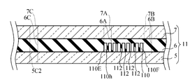
- FIG. 5 is a cross-sectional view of the cell separation unit of the cell capture device, taken along line VV of FIG. 2;
- FIG. 5 is an enlarged view of portion VI of FIG. 4;
- FIG. 5 is a cross-sectional view of a cell capture unit of the cell capture device, taken along line VV of FIG.
- FIG. 2 It is a top view which shows the outline of a cell capture unit.
- FIG. 5 is a cross-sectional view of the cell capture unit in a compressed state. It is a top view which shows the connection plate of a cell capture device.
- FIG. 12 is a cross-sectional view of a connection flat plate viewed along line XII-XII in FIG. It is an image of a photograph showing cancer cells and experimental particles separated in a cell separation unit. It is an image of a photograph showing a cancer cell captured by a cell capture unit. It is a schematic diagram which shows the manufacturing process of the mold which manufactures the cell separation flow-path plate of a cell separation unit. It is a schematic diagram which shows the process of the back of FIG.
- FIG. 18 is a schematic view showing a step after Fig. 17; It is a schematic diagram which shows the produced mold. It is a schematic diagram which shows the process of manufacturing a cell separation flow-path plate with a mold. It is a schematic diagram which shows the process of adhering a cell separation flow-path plate to a cell separation lower plate.
- Fig. 5 is a schematic view showing a process of forming a cell capture well of a cell capture unit.
- FIG. 23 is a schematic view showing a step after FIG. 22.
- FIG. 24 is a schematic view showing a step after FIG. 23;
- FIG. 25 is a schematic view showing a step after FIG. 24.
- FIG. 5 is a schematic diagram showing cell capture wells formed on a cell capture plate.
- FIG. 6 is a schematic view showing the step of adhering a cell trapping channel plate to a cell trapping lower plate. It is a front view showing a cell capture device concerning a modification of an embodiment. It is a top view which shows the cell capture device of FIG. It is a perspective view which decomposes
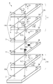
- the cell capture device 1 includes a plurality of stacked plates, specifically, a cell capture lower side plate 2, a cell capture flow path plate 3, and a connection plate. 4, a cell separation lower plate 5, a cell separation channel plate 6, and a cell separation upper plate 7 having a laminate structure.
- Fixing through holes 2 h are formed at the four corners of the cell capture lower plate 2.
- Fixing through holes 3 h are formed at the four corners of the cell trapping flow channel plate 3.
- fixing through holes 4h are formed.
- Fixing through holes 5 h are formed at the four corners of the cell separation lower plate 5.
- Fixing through holes 6 h are formed at the four corners of the cell separation flow channel plate 6.
- Fixing through holes 7 h are formed at four corners of the cell separation upper plate 7.
- the body of the pin 8 having the head 8a is inserted into the fixing through holes 2h, 3h, 4h, 5h, 6h and 7h, and is fixed to the external thread of the upper part of the pin 8.
- a nut 9 as a tool is attached.
- the cell capture lower side plate 2, the cell capture flow path plate 3, the connection plate 4, the cell separation lower side plate 5, the cell separation flow path plate 6, and the cell separation upper side plate 7 are integrated.
- the fixture is not limited to the nut 9 and may be another fixture.
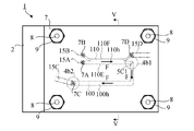
- the cell separation lower plate 5, the cell separation channel plate 6, and the cell separation upper plate 7 constitute a plate-like cell separation unit 11.
- the fixing through holes 5 h, 6 h, 7 h constitute a fixing through hole 11 h of the cell separation unit 11.
- the cell capture lower side plate 2 and the cell capture flow path plate 3 constitute a plate-like cell capture unit 10 disposed below the cell separation unit 11 and fixed to the cell separation unit 11.
- the fixing through holes 2 h, 3 h, 4 h constitute a fixing through hole 10 h of the cell capture unit 10.
- the cell capture unit 10 is used to capture specific types of cells (eg, CTCs) at specific positions for analysis using the DEP action. Also, a cell capture unit 10 may be used to analyze captured cells.
- the cell separation unit 11 is used for pretreatment of the capture process. Specifically, the cell separation unit 11 separates cells of a specific type contained in a sample liquid (eg, blood) from other cells, and extracts liquid surrounding cells of a specific type from sample liquid components. It is used to replace the carrier fluid with a conductivity different from that of the cells.
- a specific type of cell captured by the cell capture unit 10 is referred to as a large cell, and other cells unnecessary for analysis are referred to as small cells.
- the cell separation unit 11 has a sample liquid inlet 7B, a carrier liquid inlet 7A, a cell separation channel 110, a large cell outlet 5C1, and a small cell outlet 7D.
- the sample liquid for example, blood
- the sample liquid injection device 15B for example, a pipette
- the sample solution contains a plurality of large cells, a plurality of small cells smaller than the large cells, and a sample liquid component.
- the carrier liquid is introduced into the carrier liquid inlet 7A from a carrier liquid injection device 15A (for example, a pipette).
- the carrier fluid has a conductivity that differs from that of the large cells and the sample fluid.
- the carrier solution may be a reagent solution for analyzing large cells in the cell capture unit 10.
- the flow of liquid is indicated by arrow F.
- the cell separation channel 110 is disposed horizontally, and the sample liquid from the sample liquid inlet 7B and the carrier liquid from the carrier liquid inlet 7A flow, and a set of a large cell and a carrier liquid, a set of small cells and a sample liquid component And separate.
- a set of large cells and a carrier liquid flows in from the cell separation channel 110 into the large cell outlet 5C1.
- the large cell outlet 5C1 guides the set of large cells and carrier fluid to the cell capture unit 10.
- a set of small cells and a sample liquid component flows from the cell separation channel 110 into the small cell outlet 7D.
- the set of small cells and sample liquid component is aspirated by the small cell and sample liquid component suction device 15D (for example, a tube connected to the suction pump P) and discharged from the small cell outlet 7D.
- the cell capture unit 10 has a large cell flow channel 100.
- the large cell flow channel 100 is arranged horizontally and leads to the large cell outlet 5C1 of the cell separation unit 11, where a set of large cells and a carrier liquid flows. While the carrier liquid flows through the large cell flow channel 100, large cells are captured, and the remaining carrier liquid is sucked and discharged by the carrier liquid suction device 15C (for example, a tube connected to the suction pump P). .
- the carrier liquid suction device 15C for example, a tube connected to the suction pump P.
- the cell separation channel plate 6 is formed with a separation channel recess 110 h to be the cell separation channel 110.
- the cell separation lower plate 5 disposed below the cell separation channel plate 6 is stacked on the cell separation channel plate 6 to close the separation channel recess 110 h.
- the cell separation lower plate 5 and the cell separation channel plate 6 cooperate to define the cell separation channel 110.
- a sample liquid inlet 6B, a carrier liquid inlet 6A and a small cell outlet 6D are formed in the cell separation flow channel plate 6. These are holes passing through the upper wall of the separation channel recess 110 h.
- the sample liquid inlet 7B, the carrier liquid inlet 7A and the small cell outlet 7D are through holes formed in the cell separation upper plate 7, and the sample liquid inlet 6B, the carrier liquid inlet 6A and the small cells of the cell separation channel plate 6 respectively. Go to Exit 6D.
- the sample liquid flows into the cell separation channel 110 through the sample liquid inlets 7B and 6B.
- the carrier liquid flows into the cell separation channel 110 through the carrier liquid inlets 7A and 6A.
- the set of small cells and sample liquid component flows out of the cell separation channel 110 to the small cell outlets 6D, 7D.
- the large cell outlet 5C1 is a through hole formed in the cell separation lower side plate 5, and a set of large cells and a carrier liquid flows in from the cell separation channel 110 here.
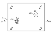
- connection plate 4 is a gasket that connects the cell capture unit 10 and the cell separation unit 11 and reduces or prevents liquid leakage between the two.
- the connection plate 4 is formed with a large cell inflow through hole 4C1 and a carrier liquid inflow through hole 4C2.
- a large cell flow channel concave portion 100 h to be the large cell flow channel 100 is formed.
- the cell capture lower side plate 2 disposed below the cell capture flow path plate 3 is stacked on the cell capture lower side plate 2 to close the large cell flow path recess 100 h. In this way, the cell capture lower plate 2 and the cell capture plate 3 cooperate to define the large cell channel 100.
- an inlet hole 3C1 and an outlet hole 3C2 of the large cell flow channel 100 are formed. These are holes passing through the upper wall of the large cell flow passage recess 100 h.
- the inlet hole 3C1 passes through the large cell outlet 5C1 of the cell separation lower plate 5 and the large cell inflow through hole 4C1 of the connection plate 4.
- a set of large cells and a carrier liquid flows from the cell separation channel 110 into the large cell channel 100 via the large cell outlet 5C1, the large cell inflow through hole 4C1, and the inlet hole 3C1.
- the carrier liquid discharge through hole 5C2 is formed in the cell separation lower side plate 5
- the carrier liquid discharge through hole 6C is formed in the cell separation channel plate 6
- the carrier liquid discharge through hole is formed in the cell separation upper plate 7 7C is formed.
- These are in communication with each other, and constitute a carrier liquid discharge through hole 11C of the cell separation unit 11.
- the outlet hole 3C2 of the large cell flow channel 100 passes through the carrier liquid inflow through hole 4C2 of the connection plate 4 and the carrier liquid discharge through hole 11C of the cell separation unit 11.
- the carrier liquid is discharged from the large cell flow channel 100 through the outlet hole 3C2 and the carrier liquid inflow through holes 4C2, 5C2, 6C, 7C.
- the cell separation flow channel plate 6 and the cell capture flow channel plate 3 are formed of a transparent elastomer, for example, silicone rubber based on polydimethylsiloxane (PDMS).
- the cell separation upper plate 7 and the cell separation lower plate 5 are made of a transparent material such as acrylic resin or glass.
- the connection flat plate 4 is a plate formed of a transparent material such as acrylic resin or glass, for example, and an annular seal 4b1, 4b2 made of an elastomer is fixed to this plate.
- the annular seals 4b1 and 4b2 will be described later.
- the cell capture lower plate 2 has a substrate formed of a transparent material such as acrylic resin or glass, an electrode for DEP and an insulating layer. The electrode for DEP and the insulating layer will be described later.
- the cell separation channel 110 includes a linear main channel 111, a carrier liquid introduction channel 110A, a sample liquid introduction channel 110B, a large cell discharge channel 110C, and a small cell discharge channel. It has 110D.
- the carrier liquid introduction channel 110A is in communication with the carrier liquid inlet 6A
- the sample liquid inlet channel 110B is in communication with the sample liquid inlet 6B
- the large cell discharge channel 110C is in communication with the large cell outlet 5C1.
- the discharge channel 110D communicates with the small cell outlet 6D.
- the carrier liquid introduction channel 110A and the sample liquid introduction channel 110B are connected to one end (that is, the upstream end) of the main channel 111, and the large cell discharge channel 110C and the small cell discharge channel 110D are connected to the main channel 111. It is connected to the other end (that is, the downstream end).
- the carrier liquid introduction channel 110A and the large cell discharge channel 110C extend on the extension of the linear main channel 111 and have a large width, while the sample liquid introduction channel 110B and the small cell discharge flow In the passage 110D, only the portion near the main flow passage 111 extends on the extension of the main flow passage 111 and has a small width.
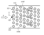
- a plurality of pillars 112 extending vertically are provided in the main channel 111 of the cell separation channel 110.
- These pillars 112 separate large cells and small cells flowing in a liquid by a deterministic lateral displacement (DLD) method.
- DLD deterministic lateral displacement
- the DLD method is a technology for separating large particles and small particles from a flow of liquid in which particles are dispersed, using a large number of columns regularly arranged in a microfluidic device.
- FIG. 7 As shown in FIG. 7, it is a top view which shows many pillars 112 utilized by DLD method.
- the large number of columns 112 form a plurality of rows, each row being inclined at an angle ⁇ to the flow direction F.
- the small particles or small cells 121 travel in zigzag with respect to the flow direction F while changing the flow direction by the columns 112, but travel roughly linearly in a laminar flow.
- the large particles or large cells 120 travel obliquely along the inclination of the row of columns 112.
- these pillars 112 bias the flow of the large cells 120 to one side 110E of the cell separation channel 110 in the horizontal plane,
- the flow of the small cells 121 is directed in the longitudinal direction of the cell separation channel 110, that is, in the flow direction F in the horizontal plane.
- D C 1.4 g ⁇ N ⁇ 0.48
- g the distance between the columns 112 in the direction perpendicular to the flow direction F
- N the number of flow streams, and is expressed by the following equation.
- N 1 / ⁇ (equation 2)
- ⁇ the row shift fraction, that is, the shift ratio of the column 112
- ⁇ tan ⁇ .
- Boundary diameter D C obtained by the equation equivalent following Equation 1.
- D C 1.4 g ⁇ ⁇ 0.48 (Equation 3)
- the boundary diameter D C is in the range of the following equation. 0.3628 g ⁇ D C ⁇ 0.4636 g (Equation 4)
- Particles having a diameter less than the boundary diameter D C generally travel along the flow direction, and particles having a diameter greater than the boundary diameter D C travel diagonally. Because CTCs are larger than other blood cells, CTCs can be separated from the sample solution (eg, blood) by the cell separation unit 11 using the DLD method.
- the number and position of the pillars 112 are not necessarily accurate.
- the cross-sectional shape in the horizontal surface of the pillar 112 is circular, the cross-sectional shape may be another shape as long as the above-described separation action is exhibited.
- the carrier liquid inlets 7A, 6A and the large cell outlet 5C1 are in the horizontal plane on one side 110E (side where large cells concentrate) of the cell separation channel 110.
- the sample liquid inlets 7B and 6B and the small cell outlets 7D and 6D are disposed on the side, and are disposed on the opposite side 110F of the cell separation channel 110 in the horizontal plane.
- the carrier liquid introduced through the carrier liquid inlets 7A and 6A flows in the vicinity of one side 110E of the cell separation channel 110 by making the liquid flowing in the cell separation channel 110 a laminar flow, and the sample liquid inlet 7B
- the sample liquid component of the sample liquid introduced through the fluid flows around the other side 110 F of the cell separation channel 110.
- the large cells are concentrated in the vicinity of the side 110E of the cell separation channel 110, and small cells flow along the longitudinal direction of the cell separation channel 110.
- the carrier liquid inlet 7A and the large cell outlet 5C1 are automatically made large according to the flow of the liquid.
- the cells and the carrier liquid flow in, and the sample liquid inlet 7B and the small cell outlet 7D are disposed on the side of the other side 110F of the cell separation channel 110 in the horizontal plane, so that the liquid flows The small cell and the sample liquid component flow into the small cell outlet 7D, 6D automatically. Therefore, large cells and small cells can be easily separated, and at the same time large cells originally contained in the sample solution can be easily transferred to the carrier solution.
- a plurality of flow straightening plates 114 are disposed downstream of the main flow passage 111, and the flow straightening plates 114 are parallel to one another. And, it is arranged parallel to the longitudinal direction of the main flow path 111.
- a similar rectified version is also arranged upstream of the main channel 111.
- the rectifying plate 114 is not necessarily essential.
- reference numeral 113 denotes a partition between the small cell discharge channel 110D and the large cell discharge channel 110C, which is disposed on the downstream side of the rectifying plate 114.
- the large cell flow channel 100 of the cell capture unit 10 will be described in detail.
- a set of large cells and a carrier liquid flows from the cell separation channel 110 into the large cell channel 100 via the large cell outlet 5C1, the large cell inflow through hole 4C1, and the inlet hole 3C1.
- the large cell flow channel 100 is defined by the cell trapping lower plate 2 and the cell trapping flow channel plate 3.
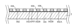
- the cell capture lower plate 2 has a substrate 101 formed of a transparent material such as, for example, acrylic resin or glass.
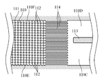
- a plurality of electrode lines 102A and 102B are disposed parallel to each other on the upper surface of the substrate 101 of the cell capture lower plate 2 in order to attract the large cells 120 by the DEP action.
- the electrode lines 102A and 102B constitute inter-digitated electrodes (IDE, Inter-Digitated Electrodes). That is, the plurality of electrode lines 102A are connected by the electrode line 102C, and the plurality of electrode lines 102B are connected by the electrode line 102D.
- FIG. 9 is a schematic view and does not accurately represent the number of electrode lines 102A and 102B and the number of cell capture wells 104 described later. Different potentials are given to the electrode line 102C and the electrode line 102D by the power supply device 105.
- the electrode lines 102A and 102B are formed of ITO (Indium Tin Oxide), but may be formed of another conductive material.
- the insulating layer 103 is formed on the electrode layer 102 having the electrode lines 102A and 102B, and the insulating layer 103 has a plurality of cells for capturing the large cells 120.
- a cell capture well 104 is formed.
- the cell capture well 104 is a circular through hole penetrating the insulating layer 103, but the shape of the cell capture well 104 is not limited to the illustration.
- the central portion of the cell capture well 104 does not overlap the electrode lines 102A and 102B, and each end of the cell capture well 104 overlaps any of the electrode lines 102A and 102B.
- Each cell capture well 104 has a diameter capable of capturing one of the large cells 120. That is, the diameter of the cell capture well 104 is larger than the diameter of the target large cell 120 and smaller than twice the diameter of the large cell 120.
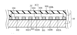
- the cell trapping channel plate 3 in which the large cell channel 100 is formed is formed of a soft elastomer, as shown in FIG. 10, the cell trapping channel plate 3 is compressed in the thickness direction to The gap between the upper wall 3T of the capture flow channel plate 3 and the substrate 101, that is, the height of the large cell flow channel 100 can be narrowed to accommodate each large cell 120 so as not to flow out into the cell capture well 104.
- the carrier liquid L may be a reagent liquid for analyzing the large cells 120 by the cell capture unit 10. Therefore, in the state shown in FIG. 10, the individual large cells 120 accommodated in the cell capture well 104 may be analyzed.
- a reagent solution containing a substance that emits fluorescence or phosphorescence in response to the components of the large cell 120 is used as the carrier liquid L, and fluorescence or phosphorescence emitted from individual large cells 120 accommodated in the cell capture well 104 is used. Changes may be observed.
- a reagent for observing the polymerase chain reaction may be used as the carrier solution L.
- the large cells 120 Prior to analysis of the large cells 120, the large cells 120 may be disrupted by applying a voltage to the large cells 120 by the electrode lines 102A and 102B, which is larger than the voltage used for cell capture.
- the reagent liquid may be introduced into the large cell flow channel 100, and thereafter, the individual large cells 120 stored in the cell capture well 104 may be analyzed.
- the reagent solution is introduced from, for example, the carrier liquid inlet 7A, as in the carrier liquid L, and the carrier liquid inlet 6A, the cell separation channel 110, the large cell outlet 5C1, the large cell inflow through hole 4C1, the inlet hole 3C1 , And through the large cell channel 100 to the large cell channel 100.
- the reagent liquid is discharged from the large cell flow path 100 through the outlet hole 3C2, the carrier liquid inflow through hole 4C2, and the carrier liquid discharge through hole 11C by the suction device 15C, similarly to the carrier liquid L.
- the cell capture channel plate 3, the connection plate 4, the cell separation lower plate 5, the cell separation channel plate 6, and the cell separation upper plate 7 above the large cell channel 100 are formed of a transparent material.
- the large cell flow channel 100 is disposed at a position different from the cell separation flow channel 110 in plan view. Therefore, it is easy to observe the large cells 120 fixed to the large cell flow channel 100 from above by visual observation or an optical instrument.
- the cell separation unit 11 and the connection plate 4 may be removed from the cell capture unit 10 before analyzing the large cells 120 immobilized in the large cell channel 100. This can be easily implemented by attaching and detaching the fixture, for example the nut 9, from the pin 8. Since the cell capture channel plate 3 above the large cell channel 100 is transparent, even after removing the cell separation unit 11 and the connection plate 4, the large cells 120 fixed to the large cell channel 100 can be viewed from above Or it is easy to observe with an optical instrument.
- connection plate 4 connecting the cell capture unit 10 and the cell separation unit 11 will be described in detail.
- the connection plate 4 is formed with a large cell inflow through hole 4C1 and a carrier liquid inflow through hole 4C2.
- the large cell inflow through hole 4C1 connects the large cell outlet 5C1 of the cell separation unit 11 and the large cell channel 100 of the cell capture unit 10, and the carrier liquid inflow through hole 4C2 is of the cell separation unit 11
- the carrier liquid discharge through hole 11C and the large cell flow path 100 of the cell capture unit 10 are connected.
- Annular seals 4b1 and 4b2 formed of an elastomer surrounding the large cell inflow through hole 4C1 and the carrier liquid inflow through hole 4C2 are fixed on the upper surface of the connection plate 4.
- the elastomer may, for example, be a silicone rubber.
- Annular seals 4b1 and 4b2 are disposed on the upper surface of the connection plate 4, ie, the surface of the cell separation unit 11 in contact with the lower cell separation plate 5, and the annular seals 4b1 and 4b2 are compressed and elastically deformed. Leakage of the carrier liquid between the cell separation unit 11 and the connection plate 4 is prevented or reduced.
- annular seals 4b1 and 4b2 are fixed to the connection plate 4, but the annular seals 4b1 and 4b2 may be separable from the connection plate 4.
- an annular seal such as an O-ring or a D-ring may be disposed between the connection plate 4 and the cell separation unit 11 as the annular seals 4b1 and 4b2.
- the cell capture device 1 has a laminate structure comprising a plurality of stacked plates.
- the elastomeric component reduces or prevents leakage from the fluid path.
- the cell separation channel plate 6 is formed of an elastomer. Therefore, when the cell separation channel plate 6 and the cell separation lower plate 5 are stacked and compressed, the cell separation channel plate 6 is in close contact with the cell separation lower plate 5, and the leakage of the liquid between them is prevented or reduced. Be done.
- the cell separation upper plate 7 and the cell separation channel plate 6 are stacked and compressed, the cell separation channel plate 6 is in close contact with the cell separation upper plate 7, and liquid leakage therebetween is prevented or reduced.
- the cell trapping channel plate 3 is formed of an elastomer, when the cell trapping channel plate 3 and the cell trapping lower plate 2 are overlapped and compressed, the cells on the cell trapping lower plate 2 The capture flow path plate 3 is in close contact and liquid leakage between them is prevented or reduced. Since the cell trapping channel plate 3 having the upper surface of the cell trapping unit 10 is formed of an elastomer, when the connecting plate 4 and the cell trapping unit 10 are stacked and compressed, the cell trapping unit 10 adheres to the connecting plate 4. Leakage of the carrier fluid between the cell capture unit 10 and the connection plate 4 is prevented or reduced. And, the leakage of the carrier liquid between the connection plate 4 and the cell separation unit 11 is prevented or reduced by the annular seal 4b1, 4b2 between them.
- elastomeric components reduce or prevent leakage from the liquid path.
- an adhesive, a chemical reaction, or a thermal reaction may be used to bond the plate to the plate.
- the spacing g of the columns 112 in the direction perpendicular to the flow direction F in the cell separation unit 11 is set to 40 ⁇ m, the number N of streamlines is 36.6, and the boundary diameter D C in the cell separation unit 11 according to the DLD method was designed to be 9.93 ⁇ m.
- a sample solution a solution prepared by adding 1 ⁇ l of 1.7 ⁇ m diameter spherical particles of polystyrene and PC3 cells (human prostate cancer cells) to 1000 ⁇ l of phosphate buffer was used. Spherical particles of polystyrene were used in place of platelets approximately 2 ⁇ m in diameter. Since the diameter of PC3 cells is about 12 to 22 ⁇ m, it was expected that the cell separation unit 11 having a boundary diameter D C of 9.93 ⁇ m could be separated from the spherical particles of polystyrene and thus platelets.
- Negative pressure was applied by the suction device 15C and the suction device 15D, and the flow rates of the carrier liquid and the sample liquid were controlled to 1.5 ⁇ l / min.
- the flow rates of the carrier liquid and the sample liquid were controlled to 1.5 ⁇ l / min.
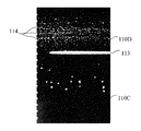
- FIG. 13 is a photographic image showing spherical particles of PC3 cells and polystyrene separated by the cell separation unit 11 obtained in this experiment. It can be understood that the large cell PC3 cells flow into the large cell discharge flow channel 110C of the cell separation flow channel 110 and the spherical particles of polystyrene flow into the small cell discharge flow channel 110D.
- the set of spherical particles of polystyrene and the sample liquid component was discharged from the small cell outlet 7D, and the set of PC3 cells and the carrier liquid was sent to the cell trapping unit 10 through the large cell outlet 5C1.
- FIG. 14 is a photographic image showing PC3 cells captured by the cell capture unit 10 obtained in this experiment. Individual PC3 cells were captured in one cell capture well 104.
- the cell capture device 1 used in the above experiment will be described.
- the following manufacturing method is an example, and the cell capture device 1 may be manufactured by other methods.
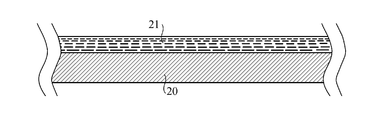
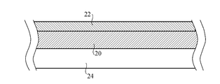
- an epoxy resin solution 21 was dropped on a P-type silicon wafer 20 (crystal orientation 100) with a diameter of 4 inches (100 mm) and homogenized by spin coating.
- a negative photoresist (trade name “SU8 3050”) manufactured by Nippon Kayaku Co., Ltd. was used. Spin coating was performed for 30 seconds at a rotational speed of 2000 rpm.
- the baking was performed for 25 minutes at a temperature of 95 ° C. using a heater 24 to form a dried epoxy resin layer 22.
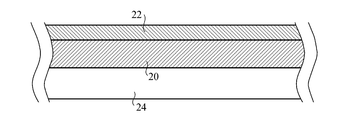
- the mask 26 was placed on the epoxy resin layer 22, and ultraviolet rays were irradiated using a mercury lamp to cure a desired portion of the epoxy resin layer 22.
- the mask 26 is used to form a portion corresponding to the cell separation channel 110 having the columns 112 of the cell separation channel plate 6 in a mold, and has a plurality of cylinders having the same size and the same shape as the plurality of columns 112.
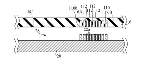
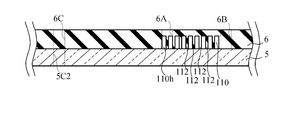
- the cell separation channel plate 6 was molded.
- the procedure is as follows. First, the mold 28 was immersed in a mold release agent (trade name "NOX FREE F-350”) manufactured by Unimatec Co., Ltd. for 1 minute, and was sufficiently dried. Next, silicone rubber (trade name “SILPOT 184”) manufactured by Toray Dow Corning Co., Ltd. was injected into the mold 28, and left at a temperature of 100 ° C. for 1 hour to cure the silicone rubber. After that, the silicone rubber cured was peeled off from the mold 28 to obtain the cell separation flow channel plate 6 made of silicone rubber to which the shape of the mold 28 was transferred.
- a mold release agent trade name "NOX FREE F-350” manufactured by Unimatec Co., Ltd. for 1 minute
- silicone rubber trade name “SILPOT 184” manufactured by Toray Dow Corning Co., Ltd. was injected into the mold 28, and left at a temperature of 100 ° C. for 1 hour to cure the silicone rubber. After that, the silicone rubber cured was peeled off from
- the carrier liquid inlet 6A, the sample liquid inlet 6B, the small cell outlet 6D, and the fixing through hole 6h of the cell separation flow channel plate 6 may be formed thereafter. These molding resin protrusions may be formed on the mold 28 and formed by resin protrusions.
- the lower cell separation plate 5 made of glass and the cell separation channel plate 6 were joined.
- the procedure of bonding is as follows. First, a large cell outlet 5C1 having a diameter of 1 mm and a carrier liquid discharge through hole 5C2 were formed in the cell separation lower plate 5. Next, oxygen plasma was irradiated to the cell separation lower side plate 5 and the cell separation flow path plate 6 using an apparatus (trade name “RIE-10 NR”) of Samco Co., Ltd. The gas flow rate at this time was 50 SCCM, the pressure was 20 Pa, the RF output was 75 W, and the discharge time was 5 seconds. And the cell irradiation lower side plate 5 and the plasma irradiation surface of the cell separation flow path plate 6 were joined.
- the junction of the cell separation lower side plate 5 and the cell separation channel plate 6 is not necessarily essential. If the cell separation unit 11 is removed from the pin 8, it may be preferable not to join these, because cleaning, washing or drying of the cell separation channel 110 is easy.
- an epoxy resin solution 31 was dropped on a substrate 101 on which ITO electrode wires 102A and 102B manufactured by Geomatec Co., Ltd. were formed, and the solution was made uniform by spin coating.
- a negative photoresist (trade name "SU 8 3005") manufactured by Nippon Kayaku Co., Ltd. was used. Spin coating was performed for 30 seconds at a rotational speed of 2000 rpm.
- pre-baking was performed for 25 minutes at a temperature of 95 ° C. using a heater 24 to form a dried epoxy resin layer 32.
- the mask 36 was placed on the epoxy resin layer 32, and ultraviolet rays were irradiated using a mercury lamp to cure a desired portion of the epoxy resin layer 32.
- the mask 36 is used to form the cell capture well 104 of the insulating layer 103 of the cell capture lower plate 2, and has a plurality of through holes of the same size and shape as the cell capture well 104.
- the cell trapping flow channel plate 3 formed of silicone rubber (trade name “SILPOT 184”) manufactured by Toray Dow Corning Co., Ltd. was joined to the cell trapping lower side plate 2.
- bonding of the cell trapping flow channel plate 3 and the cell trapping lower plate 2 is not necessarily essential. It may be preferable not to join them, since it is easy to clean, wash or dry the large cell channel 100 when the cell capture unit 10 is removed from the pin 8.
- connection plate 4 Next, a method of manufacturing the connection plate 4 will be described. First, the large cell inflow through hole 4C1 and the carrier liquid inflow through hole 4C2 were formed in a glass plate. Next, using screen printing, silicone rubber (trade name "KE-1935-A / B" manufactured by Shin-Etsu Chemical Co., Ltd., large cell inflow through hole 4C1 on the upper surface of connection plate 4 and carrier liquid inflow through hole The silicone rubber was applied to a thickness of 200 ⁇ m around 4 C 2. The silicone rubber is a material of the annular seals 4 b 1 and 4 b 2 and the inner diameter of the annular seals 4 b 1 and 4 b 2 was set to 1 mm. Then, the silicone rubber was cured.
- silicone rubber trade name "KE-1935-A / B” manufactured by Shin-Etsu Chemical Co., Ltd.
- the cell capture lower side plate 2, the cell capture flow path plate 3, the connection plate 4, the cell separation lower side plate 5, the cell separation flow path plate 6 and the cell separation upper side plate 7 prepared as described above were stacked.
- a plurality of pins 8 were inserted into the fixing through holes 11 h and 10 h to align the positions of these plates. Further, these plates were fixed by the nut 9 and the cell catching flow channel plate 3, the cell separation flow channel plate 6 and the annular seals 4b1 and 4b2 were appropriately compressed to seal the fluid path.
- the fixing through holes 11h and 10h may be formed before the lamination of the plates. However, it may be formed after laminating the plates and aligning their positions.
- the cell separation channel 110 of the cell separation unit 11 includes the set of the large cell and the carrier liquid, the small cell, and the sample liquid component from the introduced sample liquid and the carrier liquid. Separate the pair. Therefore, large cells and small cells can be easily separated, and at the same time large cells originally contained in the sample solution can be easily transferred to the carrier solution.
- the cell capture unit 10 fixed to the cell separation unit 11 receives a set of large cells and a carrier liquid. While the set of large cells and carrier liquid flows in the large cell flow channel 100 of the cell capture unit 10, a plurality of large cells are transferred to any one of the plurality of cell capture wells 104 of the cell capture unit 10 by dielectrophoretic action. It is captured. By integrating the cell separation unit 11 and the cell capture unit 10, it is possible to reduce contamination when transferring the large cell and carrier solution separated by the cell separation unit 11 to the cell capture unit 10. It is possible.
- the cell separation unit 11 and the cell capture unit 10 can be easily positioned by inserting the plurality of pins 8 into the fixing through holes 11 h and 10 h of the cell separation unit 11 and the cell capture unit 10.
- the cell separation unit 11 and the cell capture unit 10 can be easily integrated by the fixing device 9.
- the cell separation unit 11 or the cell capture unit 10 can be easily replaced.
- the cell separation unit 11 and the connection plate 4 may be removed from the cell capture unit 10 before analyzing the large cells 120 immobilized in the large cell channel 100.
- the cell separation unit 11 is disposed below the cell separation channel plate 6 in which the separation channel recess 110 h to be the cell separation channel 110 is formed, and the cell separation channel plate 6. And a cell separation lower plate 5 stacked on the cell separation channel plate 6 and closing the separation channel recess 110 h. Therefore, the cell separation flow is achieved by combining the cell separation flow path plate 6 in which the separation flow path recess 110 h is formed with the cell separation lower side plate 5 which is a simple plate even if the large cell outlet 5 C 1 is formed.
- the passage 110 can be easily formed.
- the cell separation flow channel plate 6 of the cell separation unit 11 is formed of a soft elastomer, it is easy to form the separation flow channel recess 110 h.
- the cell separation channel plate 6 is formed of an elastomer, when the cell separation channel plate 6 and the cell separation lower plate 5 are stacked and compressed, the cell separation channel plate 6 is formed on the cell separation lower plate 5. It adheres and liquid leakage between them is prevented or reduced.
- the cell separation unit 11 has the cell separation upper plate 7 disposed above the cell separation flow path plate 6 and stacked on the cell separation flow path plate 6, and the sample liquid inlet 7 B
- the carrier solution inlet 7A and the small cell outlet 7D penetrate the cell separation upper plate 7. Therefore, the cell separation channel plate 6 formed of a soft elastomer can be protected by the cell separation upper plate 7.
- the liquid injection device 15B or 15A or the liquid suction device 15D comes into contact with each of the sample liquid inlet 7B, the carrier liquid inlet 7A, and the small cell outlet 7D, so the sample liquid inlet 7B, the carrier liquid inlet 7A, By providing the small cell outlet 7D in the cell separation upper plate 7, the possibility that the cell separation channel plate 6 is damaged by the injection device 15B, 15A or the suction device 15D is prevented or reduced.
- the cell trapping unit 10 is disposed below the cell trapping flow path plate 3 and the cell trapping flow path plate 3 in which the large cell flow path concave portion 100 h to be the large cell flow path 100 is formed.
- the insulating layer 103 in which the electrode layer 102 having the plurality of electrode lines 102A and 102B and the plurality of cell trapping wells 104 are formed, while being stacked on the cell trapping channel plate 3 and closing the large cell channel recess 100h.
- the cell capture lower plate 2 is stacked.
- the cell trapping flow channel plate 3 of the cell trapping unit 10 is formed of a soft elastomer, it is easy to form the large cell flow channel concave portion 100h.
- the cell capture flow channel plate 3 can be compressed in the thickness direction to narrow the height of the large cell flow channel 100 so that each large cell can be stored so as not to flow out into the cell capture well 104.
- the cell trapping channel plate 3 is formed of an elastomer, when the cell trapping channel plate 3 and the cell trapping lower plate 2 are stacked and compressed, the cell trapping channel plate 3 is formed on the cell trapping lower plate 2. It adheres and liquid leakage between them is prevented or reduced.
- the cell separation unit 11 is formed with the sample liquid inlet 7B, the carrier liquid inlet 7A, the small cell outlet 7D, and the small cell outlet 7D. Since all of these ports are formed in the cell separation unit 11, a small area of the cell capture device 1 can be effectively utilized.
- the sample liquid injection device 15B, the carrier liquid injection device 15A, the small cell and sample liquid component suction device 15D, and the carrier liquid suction device 15C can be rapidly deployed.
- FIG. 28 and 29 show a cell capture device 1A according to a modification of the embodiment.
- FIG. 30 is an exploded top view of the cell capture device 1A.
- the large cell flow channel 100 is not shown in FIG. 29, and the cell capture unit 10 is not shown in FIG.
- the cell capture device 1A includes a sample liquid dilution unit 40 in addition to the configuration of the cell capture device 1 described above.
- the sample liquid dilution unit 40 is disposed above the cell separation unit 11.
- the sample liquid dilution unit 40 has stacked dilution unit lower flat plates (lower flat plates) 41, dilution flow channel plates (flow channel plates) 42, and dilution unit upper flat plates (upper flat plates) 43.
- the sample liquid dilution unit 40 is used for pretreatment of cell separation processing in the cell separation unit 11. Specifically, a sample stock solution (for example, blood) and a dilution liquid (for example, physiological saline) are introduced into the sample liquid dilution unit 40, and the sample liquid dilution unit 40 The mixed and reduced concentration sample liquid is supplied to the sample liquid inlet 7B of the cell separation unit 11.
- a sample stock solution for example, blood
- a dilution liquid for example, physiological saline
- the upper plate 43 is formed with a sample stock solution inlet 43B and a dilution solution inlet 43E, which are through holes, respectively.
- the sample stock solution is introduced into the sample stock solution inlet 43B from a sample liquid injection device 15B (for example, a pipette).
- Dilution fluid is introduced into the dilution fluid inlet 43E from a dilution fluid injection device 15E (for example, a pipette).
- a dilution channel recess (concave portion) 400h to be a dilution channel 400 is formed in the flow channel plate 42, and the lower flat plate 41 disposed below the flow channel plate 42 is superimposed on the flow channel plate 42. Thus, the recess 400 h is closed. Thus, the lower flat plate 41 and the flow channel plate 42 cooperate to define the dilution flow channel 400.
- the dilution channel 400 is arranged horizontally.
- a sample stock solution inlet 42B and a dilution solution inlet 42E are formed.
- the sample stock solution inlet 42B and the dilution solution inlet 42E are holes passing through the upper wall of the recess 400h and respectively pass through the sample stock solution inlet 43B and the dilution solution inlet 43E of the upper flat plate 43.
- the sample stock solution flows into the dilution channel 400 via the sample stock solution inlets 43B and 43B.
- the diluent flows into the dilution channel 400 via the diluent inlets 43E and 44E.
- the sample stock solution and the dilution solution flow and are mixed to generate a diluted sample solution having a uniform concentration.
- the lower flat plate 41 is formed with a sample liquid outlet 41 B which is a through hole.
- the diluted sample liquid flows from the dilution channel 400 into the sample liquid outlet 41B.
- the sample liquid outlet 41 B passes to the sample liquid inlet 7 B of the cell separation unit 11. Therefore, the mixed solution diluted as the sample solution flows into the cell separation channel 110 of the cell separation unit 11 from the sample solution inlet 7B.
- the sample liquid dilution unit 40 also has a function of transferring the carrier liquid to the cell separation unit 11 disposed below.
- the upper flat plate 43, the flow path plate 42, and the upper flat plate 43 are formed with through holes concentric with each other, and these through holes form a transport liquid inlet 40A vertically penetrating the sample liquid dilution unit 40.
- the carrier liquid is introduced into the carrier liquid inlet 40A from a carrier liquid injection device 15A (for example, a pipette).
- the carrier liquid inlet 40A passes through the carrier liquid inlet 7A of the cell separation unit 11. Therefore, the transport fluid flows into the cell separation channel 110 of the cell separation unit 11 from the transport fluid inlet 40A through the transport fluid inlet 7A.
- the sample liquid dilution unit 40 also has a function of transferring the set of small cells and sample liquid components separated by the cell separation unit 11 from the cell separation unit 11 upward.
- the upper flat plate 43, the flow channel plate 42, and the upper flat plate 43 are formed with through holes concentric with one another, and these through holes constitute a small cell outlet 40D vertically penetrating the sample liquid dilution unit 40.
- the small cell outlet 40D passes to the small cell outlet 7D of the cell separation unit 11.
- the set of small cells and sample liquid component is aspirated by the small cell and sample liquid component suction device 15D (for example, a tube connected to the suction pump P) and discharged from the small cell outlet 7D through the small cell outlet 40D. Ru.
- the sample liquid dilution unit 40 also has a function of transferring the remaining carrier liquid from which large cells have been removed by the cell capture unit 10 from the cell separation unit 11 upward.
- the upper flat plate 43, the flow path plate 42, and the upper flat plate 43 have through holes concentric with each other, and these through holes constitute a transport liquid discharge through hole 40C vertically penetrating the sample liquid dilution unit 40. Do.
- the carrier liquid discharge through hole 40 C passes through the carrier liquid discharge through hole 7 C of the cell separation unit 11 and thus the large cell flow channel 100 of the cell capture unit 10.
- the remaining carrier liquid from which large cells have been removed by the cell capture unit 10 is aspirated by the carrier liquid suction device 15C (for example, a tube connected to the suction pump P), and the carrier liquid is discharged from the carrier liquid discharge through hole 7C. It is discharged through the through hole 40C.
- the carrier liquid suction device 15C for example, a tube connected to the suction pump P
- the carrier liquid inlet 40A, the small cell outlet 40D, and the carrier liquid discharge through hole 40C are formed in the sample liquid dilution unit 40 disposed above the cell capture unit 10 and the cell separation unit 11. Since the sample stock solution inlet 42B and the dilution liquid inlet 42E are also formed in the sample liquid dilution unit 40, the small area of the cell capture device 1A can be effectively used. Further, for example, the sample liquid injection device 15B, the dilution liquid injection device 15E, the carrier liquid injection device 15A, the small cell and sample liquid component suction device 15D, and the carrier liquid suction device 15C can be rapidly deployed. .
- Fixing through holes concentric with one another are formed at the four corners of the upper flat plate 43, the flow path plate 42, and the upper flat plate 43, and these fixing through holes pass through the sample liquid dilution unit 40 for fixing.
- the through hole 40 h is configured.
- the body of the pin 8 inserted into the fixing through holes 2h, 3h, 4h, 5h, 6h, 7h is inserted into the fixing through hole 40h.
- a nut 9 as a fixture is attached to the upper male screw portion of the pin 8 so that the cell capture unit 10, the cell separation unit 11 and the sample liquid dilution unit 40 are integrated.
- the flow path plate 42 is formed of a transparent elastomer, for example, a silicone rubber based on PDMS.
- the upper flat plate 43 and the lower flat plate 41 are made of, for example, a transparent material such as acrylic resin or glass.
- the flow path plate 42 adheres to the lower flat plate 41. Liquid leakage between them is prevented or reduced, and the upper flat plate 43 is in close contact with the flow path plate 42, and liquid leakage therebetween is prevented or reduced.
- annular seals 44A, 44B, 44C and 44D made of elastomer are fixed.
- the annular seals 44A, 44B, 44C, 44D may be the same as the annular seals 4b1, 4b2.
- Annular seals 44A, 44B, 44C, and 44D surround the carrier liquid inlet 7A, the sample liquid inlet 7B, the carrier liquid discharge through hole 7C, and the small cell outlet 7D, respectively.
- Annular seals 44A, 44B, 44C, 44D are disposed on the upper surface of the cell separation upper plate 7, that is, the surface contacting the lower plate 41 of the sample liquid dilution unit 40, and the annular seals 44A, 44B, 44C, 44D By compression and elastic deformation, the leakage of the carrier liquid between the cell separation unit 11 and the sample liquid dilution unit 40 is prevented or reduced.
- annular seals 44A, 44B, 44C, 44D are fixed to the cell separation upper plate 7, but the annular seals 44A, 44B, 44C, 44D may be separable from the cell separation upper plate 7.
- annular seal such as an O-ring or a D-ring may be disposed between the cell separation upper plate 7 and the sample liquid dilution unit 40 as the annular seals 44A, 44B, 44C, 44D.
- the sample liquid dilution unit 40 is transparent, and the liquid flow in the sample liquid dilution unit 40 and the cell separation unit 11 and the state of the liquid flow or particles in the cell capture unit 10 are recognized from above by visual observation or optical instrument It is easy to do.
- the dilution channel 400 has an inlet path leading to the sample stock solution inlet 42B, an inlet path leading to the diluent inlet 42E, a main path leading to these inlet paths, a main path and a sample liquid outlet 41B.
- Have an exit path connecting The main path is bent in a zigzag.
- the sample fluid diluted by the sample fluid dilution unit 40 can be supplied to the cell separation unit 11. Therefore, clogging of liquid in the flow path in the cell separation unit 11 and the cell capture unit 10 can be prevented or reduced.
- the zigzag main path of the dilution flow path 400 contributes to the thorough mixing of the sample stock solution and the dilution liquid to make the concentration of the sample liquid uniform.
- a mold for manufacturing the flow channel plate 42 is generated by a method similar to the method shown in FIGS.
- the mold has a silicon wafer 20 and a residual resin protrusion, and the residual resin protrusion corresponds to the dilution channel 400, the sample stock solution inlet 42B and the diluent inlet 42E.
- a flow path plate 42 made of silicone rubber is obtained.
- the lower flat plate 41 made of glass and the flow path plate 42 may be joined.
- the cell capture device 1 of the above embodiment is used to separate and capture cancer cells in a sample solution from small cells, but may be used to separate cells other than cancer cells. Good.
- cell separation unit 11 of cell capture device 1 to separate red blood cells from smaller platelets, or white blood cells from smaller platelets, use cell separation unit 11 of cell capture device 1 and separate separated red blood cells or white blood cells in cell capture unit 10. It may be captured.
- the cell separation upper plate 7 of the cell separation unit 11 is provided to protect the cell separation channel plate 6 made of soft elastomer.
- the cell separation upper plate 7 is not necessarily essential.
- connection plate 4 which is a gasket between the cell separation unit 11 and the cell capture unit 10 in the above embodiment is not necessarily essential.
- the cell capture channel plate 3 of the cell separation unit 11 is formed of an elastomer, and by overlapping and compressing it on the cell separation lower plate 5 of the cell capture unit 10, liquid leakage between them is prevented or Reduced. Furthermore, in order to improve the sealing of the flow path between the two, as shown in FIG. 31, even if the annular seals 4b1 and 4b2 are disposed between the cell trapping flow channel plate 3 and the cell separation lower plate 5 Good. In this case, the annular seals 4b1 and 4b2 may be fixed to or separated from either the cell capture flow channel plate 3 or the cell separation lower plate 5.
- the cell trapping flow channel plate 3, the connection plate 4, the cell separation lower side plate 5, the cell separation flow channel plate 6 and the cell separation upper surface plate 7 of the embodiment of FIG. 1 described above are formed of a transparent material. Further, the cell trapping flow channel plate 3, the cell separation lower side plate 5, the cell separation flow channel plate 6 and the cell separation upper plate 7 of the modification of FIG. 31 are formed of a transparent material. For this reason, it is easy to recognize the state of the flow or the particles of the liquid in the large cell flow channel 100 and the cell separation flow channel 110 from above by visual observation or an optical instrument. However, it is not necessary that all of them be transparent, and it is preferable if at least a portion above the cell separation flow channel plate 6 and at least a portion above the cell capture well 104 are transparent.
- FIGS. 8 to 10 different potentials are applied to the electrode lines 102A and 102B disposed on the same plane of the cell capturing unit 10 according to the above embodiment, and an electric field is applied to the transport liquid L in the lateral direction.
- an electrode 106 facing the electrode wires 102A and 102B may be provided on the lower surface of the upper wall 3T of the cell trapping flow channel plate 3.
- the same potential is applied to the electrode lines 102A and 102B, a different potential is applied to the electrode 106, and an electric field acts on the transport liquid L in the vertical direction.
- the cell separation unit is A sample liquid inlet into which a sample liquid containing a plurality of large cells, a plurality of small cells smaller than the large cells, and a sample liquid component is introduced; A carrier liquid inlet into which a carrier liquid having a conductivity different from that of the large cells is introduced; The sample liquid from the sample liquid inlet and the carrier liquid from the carrier liquid inlet flow horizontally, and a set of the large cells and the carrier liquid, a set of the small cells and the sample liquid component, and the like.
- a cell separation channel for separating A large cell outlet through which the large cells and the carrier liquid flow from the cell separation channel; A small cell outlet through which the small cells and the set of sample liquid components flow from the cell separation channel;
- the cell capture unit is A large cell flow path disposed horizontally and communicating with the large cell outlet of the cell separation unit, and through which a set of the large cell and the carrier liquid flows; And a plurality of electrode lines for attracting the large cells flowing through the large cell flow channel by dielectrophoresis.
- a cell capture device characterized in that a plurality of cell capture wells each having a size capable of capturing one of the large cells attracted by the electrode wire are formed in the large cell flow channel.
- Each of the cell separation channels extends vertically inside, and the flow of the large cells is biased to one side of the cell separation channel in the horizontal plane, and the flow of the small cells is in the horizontal plane.
- a plurality of columns are provided, oriented in the longitudinal direction of the cell separation channel, The carrier liquid inlet and the large cell outlet are disposed on the side of the one side of the cell separation channel in a horizontal plane, The cell capture device according to claim 1, wherein the sample liquid inlet and the small cell outlet are disposed on the other side of the cell separation channel in a horizontal plane.
- the carrier liquid introduced through the carrier liquid inlet flows near the one side of the cell separation channel and is introduced through the sample liquid inlet
- the sample liquid component of the sample liquid flows near the other side of the cell separation channel.
- sample fluid inlet and the small cell outlet are arranged on the other side of the cell separation channel in the horizontal plane so that the small cell outlet is automatically moved to the small cell outlet as the liquid flows. And sample liquid components flow in. Therefore, large cells and small cells can be easily separated, and at the same time large cells originally contained in the sample solution can be easily transferred to the carrier solution.
- a plurality of fixing through holes are formed in the cell separation unit, A plurality of fixation through holes are formed in the cell capture unit, The fixing through hole of the cell separation unit, and a plurality of pins inserted into the fixing through hole of the cell capturing unit;
- the cell capture device according to clause 1 or 2 further comprising: a plurality of fixtures attached to the pins to fix the cell separation unit and the cell capture unit.
- the cell separation unit and the cell capture unit can be easily positioned by inserting a plurality of pins into the fixation through holes of the cell separation unit and the cell capture unit, and the cell separation unit can be fixed by the fixture.
- the cell capture unit can be easily integrated. Also, cell separation units or cell capture units can be easily replaced.
- the cell separation unit is A cell separation channel plate in which a separation channel concave portion to be the cell separation channel is formed; A cell separation lower plate disposed below the cell separation flow path plate and stacked on the cell separation flow path plate to close the separation flow path recess; The cell trapping device according to any one of Items 1 to 3, wherein the large cell outlet penetrates the cell separation lower plate.
- the cell separation flow path is formed by combining the cell separation flow path plate in which the separation flow path recess is formed with the cell separation lower side plate, which is a simple plate even if the large cell outlet is formed. Can be easily formed.
- the cell separation channel plate is formed of a soft elastomer, it is easy to form the separation channel recess. Further, since the cell separation channel plate is formed of an elastomer, when the cell separation channel plate and the cell separation lower plate are stacked and compressed, the cell separation channel plate adheres to the cell separation lower plate, Fluid leakage is prevented or reduced.
- the cell separation unit further includes a cell separation upper plate disposed above the cell separation channel plate and stacked on the cell separation channel plate; 5.
- the cell separation channel plate formed of a soft elastomer can be protected by the cell separation upper plate.
- Each of the sample liquid inlet, the carrier liquid inlet, and the small cell outlet is in contact with a liquid injector or a liquid suction device, so that the sample liquid inlet, the carrier liquid inlet, and the small cell outlet are separated from the cell separation top plate.
- the cell capture unit is A cell capture flow channel plate in which a large cell flow channel concave portion to be the large cell flow channel is formed;
- the electrode layer having the plurality of electrode lines and the plurality of cell trapping wells are disposed below the cell trapping channel plate and stacked on the cell trapping channel plate to close the large cell channel recess, and
- the cell trap channel plate is formed of a soft elastomer, it is easy to form a large cell channel recess.
- the cell trap channel plate can be compressed in the thickness direction to narrow the height of the large cell channel so that each large cell can be stored so as not to flow out into the cell trap well.
- the cell trapping channel plate is formed of an elastomer, when the cell trapping channel plate and the cell trapping lower plate are stacked and compressed, the cell trapping channel plate is in close contact with the cell trapping lower plate. Fluid leakage is prevented or reduced.
- a large cell inflow through hole is disposed between the cell separation unit and the cell capture unit, and connects the large cell outlet of the cell separation unit and the large cell flow path of the cell capture unit. Further equipped with a connection plate, An annular seal formed of an elastomer, which is in contact with the cell separation unit, is disposed on the upper surface of the connection plate, the annular seal surrounding the large cell inflow through hole, any one of the items 1 to 8 The cell capture device as described in.
- the annular seal is disposed on the upper surface of the connection plate disposed between the cell separation unit and the cell capture unit to prevent the leakage of the carrier liquid between the cell separation unit and the connection plate or Reduced. Furthermore, in this case, when the top surface of the cell capture unit is formed of an elastomer, the cell capture unit adheres to the connection plate, so that the leakage of the carrier liquid between the cell capture unit and the connection plate is prevented or reduced. Ru.
- the cell separation unit is formed with a carrier liquid discharge through hole which is in communication with the large cell flow channel of the cell capture unit and from which the carrier liquid is discharged from the large cell flow channel.
- a carrier fluid discharge through hole is formed in the cell separation unit disposed above the cell capture unit. Since the cell separation unit is also formed with the sample liquid inlet, the carrier liquid inlet, and the small cell outlet, a small area can be effectively used.
- a large cell inflow through hole is disposed between the cell separation unit and the cell capture unit, and connects the large cell outlet of the cell separation unit and the large cell flow path of the cell capture unit.
- a connection plate having a carrier liquid inflow through hole connecting the carrier liquid discharge through hole of the cell separation unit and the large cell flow path of the cell capture unit,
- An annular seal formed of an elastomer is disposed on the upper surface of the connection plate so as to surround the large cell inflow through hole and the carrier liquid inflow through hole, respectively, and contact the cell separation unit.
- the annular seal is disposed on the upper surface of the connection plate disposed between the cell separation unit and the cell capture unit to prevent the leakage of the carrier liquid between the cell separation unit and the connection plate or Reduced. Furthermore, in this case, when the top surface of the cell capture unit is formed of an elastomer, the cell capture unit adheres to the connection plate, so that the leakage of the carrier liquid between the cell capture unit and the connection plate is prevented or reduced. Ru.
- the cell separation unit further comprises a plate-like sample liquid dilution unit disposed above the cell separation unit and fixed to the cell separation unit.
- the sample liquid dilution unit is A sample stock solution inlet into which the sample stock solution is introduced; A dilution fluid inlet into which the dilution fluid is introduced; A dilution flow path disposed horizontally, wherein the sample stock solution from the sample stock solution inlet and the dilution liquid from the dilution liquid inlet flow, and the sample stock solution and the dilution liquid are mixed to form the sample liquid; And a sample liquid outlet through which the sample liquid flows from the dilution channel;
- the cell capture device according to any one of Items 1 to 13, wherein the sample liquid outlet is in communication with the sample liquid inlet of the cell separation unit.
- the sample fluid diluted by the sample fluid dilution unit can be supplied to the cell separation unit. Therefore, clogging of the fluid in the flow path in the cell separation unit and the cell capture unit can be prevented or reduced.
- the sample stock solution and the dilution solution can be sufficiently mixed to make the concentration of the sample solution uniform.
- the sample liquid dilution unit is A carrier liquid inlet, which is a through hole which is in communication with the carrier liquid inlet of the cell separation unit and into which the carrier liquid is introduced;
- a small cell outlet which is a through-hole which is in communication with the small cell outlet of the cell separation unit and through which a set of the small cell and the sample liquid component is discharged;
- the carrier liquid discharge through hole which is a through hole which is in communication with the large cell flow channel of the cell trapping unit and through which the carrier liquid is discharged from the large cell flow channel;
- the cell trapping device as described.
- the carrier liquid inlet, the small cell outlet, and the carrier liquid discharge through-hole are formed in the sample liquid dilution unit disposed above the cell capture unit and the cell separation unit.
- the sample liquid dilution unit is also formed with a sample stock solution inlet and a dilution liquid inlet, so that a small area of the cell capture device can be effectively utilized.
- the sample liquid dilution unit is A dilution flow passage plate in which a dilution flow passage concave portion to be the dilution flow passage is formed; A dilution unit lower flat plate disposed below the dilution flow channel plate and stacked on the dilution flow channel plate to close the dilution flow channel recess; A dilution unit upper plate disposed above the dilution flow channel plate and having the sample stock solution inlet and the dilution liquid inlet; The sample solution outlet penetrates the dilution unit lower plate,
- the cell trapping device according to any one of clauses 14 to 16, wherein the dilution flow channel plate is formed of an elastomer.
- the dilution channel plate is formed of a soft elastomer, it is easy to form the separation channel recess. Further, since the dilution channel plate is formed of an elastomer, when the dilution unit upper plate, the dilution channel plate and the dilution unit lower plate are stacked and compressed, the dilution channel plate on the dilution channel upper plate and the dilution unit lower side The plates are in intimate contact and liquid leakage between them is prevented or reduced.
- An annular seal formed of an elastomer is disposed on the top surface of the cell separation unit, the annular seal surrounding the sample liquid inlet and in contact with the sample liquid dilution unit.
Abstract
Un dispositif de capture de cellules est pourvu d'une unité de séparation de cellules de type plaque plate et d'une unité de capture de cellules de type plaque plate disposée en dessous de l'unité de séparation de cellules. Dans un trajet d'écoulement de séparation de cellules dans l'unité de séparation de cellules, une solution d'échantillon et un flux de liquide porteur. La solution d'échantillon contient de multiples cellules de grande taille, de multiples cellules de petite taille, et un composant liquide d'échantillon. Le trajet d'écoulement de séparation de cellules peut séparer une fraction contenant les grandes cellules et le liquide porteur à partir d'une fraction contenant les petites cellules et le composant liquide d'échantillon. L'unité de capture de cellule est pourvue d'un trajet d'écoulement de grandes cellules à travers lequel la fraction contenant les grandes cellules et le liquide porteur s'écoule et de multiples fils d'électrode pour étirer les grandes cellules par une action diélectrophorétique. Dans le trajet d'écoulement des grandes cellules, de multiples puits de capture de cellule sont formés, dont chacun a une taille telle qu'une des grandes cellules tirées par les fils d'électrode peut être capturée par chacun des puits de capture de cellule.
Priority Applications (4)
| Application Number | Priority Date | Filing Date | Title |
|---|---|---|---|
| JP2019536315A JP6620269B2 (ja) | 2017-10-03 | 2018-10-02 | 細胞捕捉装置 |
| US16/753,207 US11421198B2 (en) | 2017-10-03 | 2018-10-02 | Cell capture apparatus |
| EP18863997.5A EP3693453B1 (fr) | 2017-10-03 | 2018-10-02 | Dispositif de capture de cellules |
| CN201880064770.9A CN111212900B (zh) | 2017-10-03 | 2018-10-02 | 细胞捕获装置 |
Applications Claiming Priority (2)
| Application Number | Priority Date | Filing Date | Title |
|---|---|---|---|
| JP2017-193145 | 2017-10-03 | ||
| JP2017193145 | 2017-10-03 |
Publications (1)
| Publication Number | Publication Date |
|---|---|
| WO2019069900A1 true WO2019069900A1 (fr) | 2019-04-11 |
Family
ID=65995119
Family Applications (1)
| Application Number | Title | Priority Date | Filing Date |
|---|---|---|---|
| PCT/JP2018/036826 WO2019069900A1 (fr) | 2017-10-03 | 2018-10-02 | Dispositif de capture de cellules |
Country Status (5)
| Country | Link |
|---|---|
| US (1) | US11421198B2 (fr) |
| EP (1) | EP3693453B1 (fr) |
| JP (1) | JP6620269B2 (fr) |
| CN (1) | CN111212900B (fr) |
| WO (1) | WO2019069900A1 (fr) |
Cited By (3)
| Publication number | Priority date | Publication date | Assignee | Title |
|---|---|---|---|---|
| WO2020090481A1 (fr) * | 2018-10-29 | 2020-05-07 | Nok株式会社 | Puce microfluidique et dispositif microfluidique |
| WO2020090480A1 (fr) * | 2018-10-29 | 2020-05-07 | Nok株式会社 | Puce microfluidique et dispositif microfluidique |
| WO2022070776A1 (fr) * | 2020-09-29 | 2022-04-07 | Nok株式会社 | Dispositif de capture de particules fines |
Families Citing this family (3)
| Publication number | Priority date | Publication date | Assignee | Title |
|---|---|---|---|---|
| EP3932562A4 (fr) * | 2019-02-27 | 2022-12-07 | Kyocera Corporation | Dispositif de mesure et de séparation de particules, et appareil de mesure et de séparation de particules |
| IT202100006980A1 (it) * | 2021-03-23 | 2022-09-23 | Sanchip Soc A Responsabilita Limitata | Dispositivo lab-on-a-chip modulare per l'analisi di fluidi |
| CA3215784A1 (fr) * | 2021-04-20 | 2022-10-27 | Thomas Buck | Procede et dispositif de capture d'au moins une cellule contenant un noyau en utilisant au moins une electrode pour un dispositif microfluidique |
Citations (6)
| Publication number | Priority date | Publication date | Assignee | Title |
|---|---|---|---|---|
| JP2010004870A (ja) * | 2008-05-30 | 2010-01-14 | Univ Of Tokyo | 細胞分離装置、細胞分離システム及び細胞分離方法 |
| JP2011000079A (ja) * | 2009-06-19 | 2011-01-06 | Univ Of Tokyo | 粒子を操作する方法及びマイクロ流体装置 |
| WO2012020711A1 (fr) * | 2010-08-09 | 2012-02-16 | 国立大学法人東京大学 | Dispositif à réseau de microcompartiments doté d'une fonction électrique et procédé d'analyse d'un objet d'inspection l'employant |
| JP2012239449A (ja) * | 2011-05-23 | 2012-12-10 | Nagoya Univ | がん細胞自動分離装置およびがん細胞自動分離方法 |
| WO2016136273A1 (fr) | 2015-02-27 | 2016-09-01 | 凸版印刷株式会社 | Procédé de séparation de cellules et dispositif associé |
| JP2017093359A (ja) | 2015-11-25 | 2017-06-01 | 一般財団法人生産技術研究奨励会 | マイクロチャンバーアレイ装置およびそれを用いた検査対象物の解析方法 |
Family Cites Families (14)
| Publication number | Priority date | Publication date | Assignee | Title |
|---|---|---|---|---|
| JP3512186B2 (ja) * | 1993-03-19 | 2004-03-29 | イー・アイ・デユポン・ドウ・ヌムール・アンド・カンパニー | 化学処理及び製造のための一体構造及び方法、並びにその使用方法及び製造方法 |
| US6607644B1 (en) * | 2000-10-31 | 2003-08-19 | Agilent Technolgoies, Inc. | Microanalytical device containing a membrane for molecular identification |
| AU2003284055A1 (en) * | 2002-10-09 | 2004-05-04 | The Board Of Trustees Of The University Of Illinois | Microfluidic systems and components |
| GB0321158D0 (en) * | 2003-09-10 | 2003-10-08 | Central Research Lab Ltd | Apparatus and method for handling cells,embryos or oocytes |
| US20070196820A1 (en) * | 2005-04-05 | 2007-08-23 | Ravi Kapur | Devices and methods for enrichment and alteration of cells and other particles |
| JP5608943B2 (ja) * | 2009-03-31 | 2014-10-22 | マイクロ化学技研株式会社 | 血漿分離装置及び方法 |
| US8934700B2 (en) | 2013-03-04 | 2015-01-13 | Caliper Life Sciences, Inc. | High-throughput single-cell imaging, sorting, and isolation |
| CN103571738A (zh) * | 2013-07-02 | 2014-02-12 | 中国人民解放军第三军医大学 | 一种基于趋化因子富集效应的微流控芯片装置及制备方法 |
| CN103343090B (zh) * | 2013-07-12 | 2014-09-17 | 湖南工程学院 | 一种集成化多功能可控细胞操纵及分析微流控芯片及应用 |
| JP2015099031A (ja) * | 2013-11-18 | 2015-05-28 | 株式会社東芝 | 半導体マイクロ分析チップ及びその製造方法 |
| CN103865752B (zh) * | 2014-03-07 | 2015-10-28 | 复旦大学附属中山医院 | 循环肿瘤细胞捕获和分类磁性微流控芯片及其制造和使用 |
| CN105647799B (zh) * | 2016-02-24 | 2018-08-10 | 西安交通大学 | 一种组合式场流分离的循环肿瘤细胞分离装置 |
| CN106148187A (zh) * | 2016-07-20 | 2016-11-23 | 国家纳米科学中心 | 用于表达egfr的单细胞分选和多基因位点检测的微流控芯片 |
| CN107058060B (zh) * | 2017-04-10 | 2019-06-21 | 东南大学 | 一种肿瘤细胞高通量分选富集微流控芯片 |
-
2018
- 2018-10-02 EP EP18863997.5A patent/EP3693453B1/fr active Active
- 2018-10-02 US US16/753,207 patent/US11421198B2/en active Active
- 2018-10-02 CN CN201880064770.9A patent/CN111212900B/zh active Active
- 2018-10-02 WO PCT/JP2018/036826 patent/WO2019069900A1/fr unknown
- 2018-10-02 JP JP2019536315A patent/JP6620269B2/ja active Active
Patent Citations (7)
| Publication number | Priority date | Publication date | Assignee | Title |
|---|---|---|---|---|
| JP2010004870A (ja) * | 2008-05-30 | 2010-01-14 | Univ Of Tokyo | 細胞分離装置、細胞分離システム及び細胞分離方法 |
| JP2011000079A (ja) * | 2009-06-19 | 2011-01-06 | Univ Of Tokyo | 粒子を操作する方法及びマイクロ流体装置 |
| WO2012020711A1 (fr) * | 2010-08-09 | 2012-02-16 | 国立大学法人東京大学 | Dispositif à réseau de microcompartiments doté d'une fonction électrique et procédé d'analyse d'un objet d'inspection l'employant |
| JP2012034641A (ja) | 2010-08-09 | 2012-02-23 | Univ Of Tokyo | 電気的機能を持つマイクロチャンバーアレイ装置およびそれを用いた検査対象物解析方法 |
| JP2012239449A (ja) * | 2011-05-23 | 2012-12-10 | Nagoya Univ | がん細胞自動分離装置およびがん細胞自動分離方法 |
| WO2016136273A1 (fr) | 2015-02-27 | 2016-09-01 | 凸版印刷株式会社 | Procédé de séparation de cellules et dispositif associé |
| JP2017093359A (ja) | 2015-11-25 | 2017-06-01 | 一般財団法人生産技術研究奨励会 | マイクロチャンバーアレイ装置およびそれを用いた検査対象物の解析方法 |
Non-Patent Citations (4)
Cited By (6)
| Publication number | Priority date | Publication date | Assignee | Title |
|---|---|---|---|---|
| WO2020090481A1 (fr) * | 2018-10-29 | 2020-05-07 | Nok株式会社 | Puce microfluidique et dispositif microfluidique |
| WO2020090480A1 (fr) * | 2018-10-29 | 2020-05-07 | Nok株式会社 | Puce microfluidique et dispositif microfluidique |
| JPWO2020090480A1 (ja) * | 2018-10-29 | 2021-06-10 | Nok株式会社 | マイクロ流体チップおよびマイクロ流体デバイス |
| JPWO2020090481A1 (ja) * | 2018-10-29 | 2021-09-02 | Nok株式会社 | マイクロ流体チップおよびマイクロ流体デバイス |
| JP7128492B2 (ja) | 2018-10-29 | 2022-08-31 | Nok株式会社 | マイクロ流体チップおよびマイクロ流体デバイス |
| WO2022070776A1 (fr) * | 2020-09-29 | 2022-04-07 | Nok株式会社 | Dispositif de capture de particules fines |
Also Published As
| Publication number | Publication date |
|---|---|
| EP3693453A1 (fr) | 2020-08-12 |
| JPWO2019069900A1 (ja) | 2019-11-14 |
| CN111212900A (zh) | 2020-05-29 |
| CN111212900B (zh) | 2023-09-29 |
| JP6620269B2 (ja) | 2019-12-11 |
| EP3693453A4 (fr) | 2020-11-25 |
| US11421198B2 (en) | 2022-08-23 |
| EP3693453B1 (fr) | 2024-03-13 |
| US20200283722A1 (en) | 2020-09-10 |
Similar Documents
| Publication | Publication Date | Title |
|---|---|---|
| WO2019069900A1 (fr) | Dispositif de capture de cellules | |
| US10293339B2 (en) | Microfluidic cartridge assembly | |
| JP6666313B2 (ja) | 微小流体システムにおける空気装置用コネクタ | |
| US10627366B2 (en) | Fluid delivery manifolds and microfluidic systems | |
| Huang et al. | Microfluidic integrated optoelectronic tweezers for single-cell preparation and analysis | |
| US20140268321A1 (en) | Device for imaging electron microscope environmental sample supports in a microfluidic or electrochemical chamber with an optical microscope | |
| ES2881221T3 (es) | Chip microfluídico, método de fabricación del mismo y dispositivo de análisis que usa el mismo | |
| US10308977B2 (en) | Device and method for processing a biological sample and analysis system for analyzing a biological specimen | |
| US10207264B2 (en) | Functional device and method of manufacturing the same | |
| JP2004180594A (ja) | 細胞培養装置 | |
| WO2019092989A1 (fr) | Puce microfluidique et dispositif microfluidique | |
| JP5754190B2 (ja) | マイクロチップ、サンプル液供給装置、サンプル液供給方法及び分析装置 | |
| CN1589399A (zh) | 用于测定生物样品产生的电信号的测定装置和测定方法 | |
| WO2022205399A1 (fr) | Puce microfluidique disposée en réseau intégré pour capturer et étirer des cellules | |
| US9610750B2 (en) | Composite structure and manufacturing method therefor | |
| Kremer et al. | Optoelectronic tweezers for medical diagnostics | |
| CN117500600A (zh) | 用于使用针对微流体设备的至少一个电极捕获至少一个有核细胞的方法和装置 | |
| Zhu et al. | Microfluidic single-cell culture chip for individual trapping, cultivation, and selective release of yeast cells |
Legal Events
| Date | Code | Title | Description |
|---|---|---|---|
| 121 | Ep: the epo has been informed by wipo that ep was designated in this application |
Ref document number: 18863997 Country of ref document: EP Kind code of ref document: A1 |
|
| ENP | Entry into the national phase |
Ref document number: 2019536315 Country of ref document: JP Kind code of ref document: A |
|
| NENP | Non-entry into the national phase |
Ref country code: DE |
|
| ENP | Entry into the national phase |
Ref document number: 2018863997 Country of ref document: EP Effective date: 20200504 |