WO2019069900A1 - Cell capturing device - Google Patents
Cell capturing device Download PDFInfo
- Publication number
- WO2019069900A1 WO2019069900A1 PCT/JP2018/036826 JP2018036826W WO2019069900A1 WO 2019069900 A1 WO2019069900 A1 WO 2019069900A1 JP 2018036826 W JP2018036826 W JP 2018036826W WO 2019069900 A1 WO2019069900 A1 WO 2019069900A1
- Authority
- WO
- WIPO (PCT)
- Prior art keywords
- cell
- channel
- cell separation
- unit
- plate
- Prior art date
Links
Images


Classifications
-
- B—PERFORMING OPERATIONS; TRANSPORTING
- B01—PHYSICAL OR CHEMICAL PROCESSES OR APPARATUS IN GENERAL
- B01L—CHEMICAL OR PHYSICAL LABORATORY APPARATUS FOR GENERAL USE
- B01L3/00—Containers or dishes for laboratory use, e.g. laboratory glassware; Droppers
- B01L3/50—Containers for the purpose of retaining a material to be analysed, e.g. test tubes
- B01L3/502—Containers for the purpose of retaining a material to be analysed, e.g. test tubes with fluid transport, e.g. in multi-compartment structures
- B01L3/5027—Containers for the purpose of retaining a material to be analysed, e.g. test tubes with fluid transport, e.g. in multi-compartment structures by integrated microfluidic structures, i.e. dimensions of channels and chambers are such that surface tension forces are important, e.g. lab-on-a-chip
- B01L3/502761—Containers for the purpose of retaining a material to be analysed, e.g. test tubes with fluid transport, e.g. in multi-compartment structures by integrated microfluidic structures, i.e. dimensions of channels and chambers are such that surface tension forces are important, e.g. lab-on-a-chip specially adapted for handling suspended solids or molecules independently from the bulk fluid flow, e.g. for trapping or sorting beads, for physically stretching molecules
-
- C—CHEMISTRY; METALLURGY
- C12—BIOCHEMISTRY; BEER; SPIRITS; WINE; VINEGAR; MICROBIOLOGY; ENZYMOLOGY; MUTATION OR GENETIC ENGINEERING
- C12M—APPARATUS FOR ENZYMOLOGY OR MICROBIOLOGY; APPARATUS FOR CULTURING MICROORGANISMS FOR PRODUCING BIOMASS, FOR GROWING CELLS OR FOR OBTAINING FERMENTATION OR METABOLIC PRODUCTS, i.e. BIOREACTORS OR FERMENTERS
- C12M47/00—Means for after-treatment of the produced biomass or of the fermentation or metabolic products, e.g. storage of biomass
- C12M47/04—Cell isolation or sorting
-
- B—PERFORMING OPERATIONS; TRANSPORTING
- B01—PHYSICAL OR CHEMICAL PROCESSES OR APPARATUS IN GENERAL
- B01L—CHEMICAL OR PHYSICAL LABORATORY APPARATUS FOR GENERAL USE
- B01L3/00—Containers or dishes for laboratory use, e.g. laboratory glassware; Droppers
- B01L3/50—Containers for the purpose of retaining a material to be analysed, e.g. test tubes
- B01L3/502—Containers for the purpose of retaining a material to be analysed, e.g. test tubes with fluid transport, e.g. in multi-compartment structures
- B01L3/5027—Containers for the purpose of retaining a material to be analysed, e.g. test tubes with fluid transport, e.g. in multi-compartment structures by integrated microfluidic structures, i.e. dimensions of channels and chambers are such that surface tension forces are important, e.g. lab-on-a-chip
- B01L3/50273—Containers for the purpose of retaining a material to be analysed, e.g. test tubes with fluid transport, e.g. in multi-compartment structures by integrated microfluidic structures, i.e. dimensions of channels and chambers are such that surface tension forces are important, e.g. lab-on-a-chip characterised by the means or forces applied to move the fluids
-
- B—PERFORMING OPERATIONS; TRANSPORTING
- B01—PHYSICAL OR CHEMICAL PROCESSES OR APPARATUS IN GENERAL
- B01L—CHEMICAL OR PHYSICAL LABORATORY APPARATUS FOR GENERAL USE
- B01L3/00—Containers or dishes for laboratory use, e.g. laboratory glassware; Droppers
- B01L3/50—Containers for the purpose of retaining a material to be analysed, e.g. test tubes
- B01L3/502—Containers for the purpose of retaining a material to be analysed, e.g. test tubes with fluid transport, e.g. in multi-compartment structures
- B01L3/5027—Containers for the purpose of retaining a material to be analysed, e.g. test tubes with fluid transport, e.g. in multi-compartment structures by integrated microfluidic structures, i.e. dimensions of channels and chambers are such that surface tension forces are important, e.g. lab-on-a-chip
- B01L3/502753—Containers for the purpose of retaining a material to be analysed, e.g. test tubes with fluid transport, e.g. in multi-compartment structures by integrated microfluidic structures, i.e. dimensions of channels and chambers are such that surface tension forces are important, e.g. lab-on-a-chip characterised by bulk separation arrangements on lab-on-a-chip devices, e.g. for filtration or centrifugation
-
- C—CHEMISTRY; METALLURGY
- C12—BIOCHEMISTRY; BEER; SPIRITS; WINE; VINEGAR; MICROBIOLOGY; ENZYMOLOGY; MUTATION OR GENETIC ENGINEERING
- C12M—APPARATUS FOR ENZYMOLOGY OR MICROBIOLOGY; APPARATUS FOR CULTURING MICROORGANISMS FOR PRODUCING BIOMASS, FOR GROWING CELLS OR FOR OBTAINING FERMENTATION OR METABOLIC PRODUCTS, i.e. BIOREACTORS OR FERMENTERS
- C12M1/00—Apparatus for enzymology or microbiology
- C12M1/26—Inoculator or sampler
-
- C—CHEMISTRY; METALLURGY
- C12—BIOCHEMISTRY; BEER; SPIRITS; WINE; VINEGAR; MICROBIOLOGY; ENZYMOLOGY; MUTATION OR GENETIC ENGINEERING
- C12M—APPARATUS FOR ENZYMOLOGY OR MICROBIOLOGY; APPARATUS FOR CULTURING MICROORGANISMS FOR PRODUCING BIOMASS, FOR GROWING CELLS OR FOR OBTAINING FERMENTATION OR METABOLIC PRODUCTS, i.e. BIOREACTORS OR FERMENTERS
- C12M3/00—Tissue, human, animal or plant cell, or virus culture apparatus
- C12M3/08—Apparatus for tissue disaggregation
-
- B—PERFORMING OPERATIONS; TRANSPORTING
- B01—PHYSICAL OR CHEMICAL PROCESSES OR APPARATUS IN GENERAL
- B01L—CHEMICAL OR PHYSICAL LABORATORY APPARATUS FOR GENERAL USE
- B01L2200/00—Solutions for specific problems relating to chemical or physical laboratory apparatus
- B01L2200/06—Fluid handling related problems
- B01L2200/0647—Handling flowable solids, e.g. microscopic beads, cells, particles
- B01L2200/0652—Sorting or classification of particles or molecules
-
- B—PERFORMING OPERATIONS; TRANSPORTING
- B01—PHYSICAL OR CHEMICAL PROCESSES OR APPARATUS IN GENERAL
- B01L—CHEMICAL OR PHYSICAL LABORATORY APPARATUS FOR GENERAL USE
- B01L2200/00—Solutions for specific problems relating to chemical or physical laboratory apparatus
- B01L2200/06—Fluid handling related problems
- B01L2200/0647—Handling flowable solids, e.g. microscopic beads, cells, particles
- B01L2200/0668—Trapping microscopic beads
-
- B—PERFORMING OPERATIONS; TRANSPORTING
- B01—PHYSICAL OR CHEMICAL PROCESSES OR APPARATUS IN GENERAL
- B01L—CHEMICAL OR PHYSICAL LABORATORY APPARATUS FOR GENERAL USE
- B01L2300/00—Additional constructional details
- B01L2300/04—Closures and closing means
- B01L2300/041—Connecting closures to device or container
-
- B—PERFORMING OPERATIONS; TRANSPORTING
- B01—PHYSICAL OR CHEMICAL PROCESSES OR APPARATUS IN GENERAL
- B01L—CHEMICAL OR PHYSICAL LABORATORY APPARATUS FOR GENERAL USE
- B01L2300/00—Additional constructional details
- B01L2300/06—Auxiliary integrated devices, integrated components
-
- B—PERFORMING OPERATIONS; TRANSPORTING
- B01—PHYSICAL OR CHEMICAL PROCESSES OR APPARATUS IN GENERAL
- B01L—CHEMICAL OR PHYSICAL LABORATORY APPARATUS FOR GENERAL USE
- B01L2300/00—Additional constructional details
- B01L2300/06—Auxiliary integrated devices, integrated components
- B01L2300/0627—Sensor or part of a sensor is integrated
- B01L2300/0645—Electrodes
-
- B—PERFORMING OPERATIONS; TRANSPORTING
- B01—PHYSICAL OR CHEMICAL PROCESSES OR APPARATUS IN GENERAL
- B01L—CHEMICAL OR PHYSICAL LABORATORY APPARATUS FOR GENERAL USE
- B01L2300/00—Additional constructional details
- B01L2300/08—Geometry, shape and general structure
- B01L2300/0809—Geometry, shape and general structure rectangular shaped
-
- B—PERFORMING OPERATIONS; TRANSPORTING
- B01—PHYSICAL OR CHEMICAL PROCESSES OR APPARATUS IN GENERAL
- B01L—CHEMICAL OR PHYSICAL LABORATORY APPARATUS FOR GENERAL USE
- B01L2300/00—Additional constructional details
- B01L2300/08—Geometry, shape and general structure
- B01L2300/0861—Configuration of multiple channels and/or chambers in a single devices
- B01L2300/0874—Three dimensional network
-
- B—PERFORMING OPERATIONS; TRANSPORTING
- B01—PHYSICAL OR CHEMICAL PROCESSES OR APPARATUS IN GENERAL
- B01L—CHEMICAL OR PHYSICAL LABORATORY APPARATUS FOR GENERAL USE
- B01L2300/00—Additional constructional details
- B01L2300/08—Geometry, shape and general structure
- B01L2300/0861—Configuration of multiple channels and/or chambers in a single devices
- B01L2300/0883—Serpentine channels
-
- B—PERFORMING OPERATIONS; TRANSPORTING
- B01—PHYSICAL OR CHEMICAL PROCESSES OR APPARATUS IN GENERAL
- B01L—CHEMICAL OR PHYSICAL LABORATORY APPARATUS FOR GENERAL USE
- B01L2300/00—Additional constructional details
- B01L2300/08—Geometry, shape and general structure
- B01L2300/0887—Laminated structure
-
- B—PERFORMING OPERATIONS; TRANSPORTING
- B01—PHYSICAL OR CHEMICAL PROCESSES OR APPARATUS IN GENERAL
- B01L—CHEMICAL OR PHYSICAL LABORATORY APPARATUS FOR GENERAL USE
- B01L2300/00—Additional constructional details
- B01L2300/12—Specific details about materials
- B01L2300/123—Flexible; Elastomeric
-
- B—PERFORMING OPERATIONS; TRANSPORTING
- B01—PHYSICAL OR CHEMICAL PROCESSES OR APPARATUS IN GENERAL
- B01L—CHEMICAL OR PHYSICAL LABORATORY APPARATUS FOR GENERAL USE
- B01L2300/00—Additional constructional details
- B01L2300/16—Surface properties and coatings
- B01L2300/168—Specific optical properties, e.g. reflective coatings
-
- B—PERFORMING OPERATIONS; TRANSPORTING
- B01—PHYSICAL OR CHEMICAL PROCESSES OR APPARATUS IN GENERAL
- B01L—CHEMICAL OR PHYSICAL LABORATORY APPARATUS FOR GENERAL USE
- B01L2400/00—Moving or stopping fluids
- B01L2400/04—Moving fluids with specific forces or mechanical means
- B01L2400/0403—Moving fluids with specific forces or mechanical means specific forces
- B01L2400/0415—Moving fluids with specific forces or mechanical means specific forces electrical forces, e.g. electrokinetic
- B01L2400/0424—Dielectrophoretic forces
-
- B—PERFORMING OPERATIONS; TRANSPORTING
- B01—PHYSICAL OR CHEMICAL PROCESSES OR APPARATUS IN GENERAL
- B01L—CHEMICAL OR PHYSICAL LABORATORY APPARATUS FOR GENERAL USE
- B01L2400/00—Moving or stopping fluids
- B01L2400/08—Regulating or influencing the flow resistance
- B01L2400/084—Passive control of flow resistance
- B01L2400/086—Passive control of flow resistance using baffles or other fixed flow obstructions
Definitions
- the present invention relates to a cell capture device that selectively isolates specific cells from sample fluid and captures these cells for analysis.
- CTC Circulating Tumor Cell
- large cells contained in the sample solution can be easily separated from the sample solution, large cells can be easily transferred to the carrier solution, and a combination of large cells and carrier solution can be captured by cells.
- a cell capture device capable of reducing contamination when moving for processing.
- a cell capture device comprises a flat cell separation unit, and a flat cell capture unit disposed below the cell separation unit and fixed to the cell separation unit, the cells
- the separation unit has a conductivity different from the conductivity of the large cells, a sample liquid inlet into which a sample liquid containing a plurality of large cells, a plurality of small cells smaller than the large cells, and a sample liquid component is introduced.
- sample liquid from the sample liquid inlet and the carrier liquid from the carrier liquid inlet flow in parallel with the carrier liquid inlet into which the carrier liquid is introduced, and a set of the large cells and the carrier liquid
- a cell separation channel separating the small cells and the set of sample liquid components; a large cell outlet through which the large cells and the carrier liquid flow from the cell separation channel; and the cells
- the small cell and the small cell outlet through which the set of the sample liquid component flows from the separation channel, and the cell capture unit is disposed horizontally and communicates with the large cell outlet of the cell separation unit;
- a large cell flow channel through which the large cells and the carrier liquid flow, and a plurality of electrode lines for attracting the large cells flowing through the large cell flow channel by dielectrophoresis;
- the channel is formed with a plurality of cell capture wells each having a size capable of capturing one of the large cells attracted by the electrode lines.
- the cell separation channel of the cell separation unit separates the set of large cells and carrier liquid and the set of small cells and sample liquid components from the introduced sample liquid and carrier liquid. Therefore, large cells and small cells can be easily separated, and at the same time large cells originally contained in the sample solution can be easily transferred to the carrier solution.
- the cell capture unit immobilized on the cell separation unit receives a set of large cells and carrier fluid. While the large cell and the carrier solution are flowing through the large cell flow channel of the cell capture unit, a plurality of large cells are respectively captured by any of the plurality of cell capture wells of the cell capture unit by dielectrophoretic action.
- FIG. 5 is a cross-sectional view of the cell separation unit of the cell capture device, taken along line VV of FIG. 2;
- FIG. 5 is an enlarged view of portion VI of FIG. 4;
- FIG. 5 is a cross-sectional view of a cell capture unit of the cell capture device, taken along line VV of FIG.
- FIG. 2 It is a top view which shows the outline of a cell capture unit.
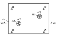
- FIG. 5 is a cross-sectional view of the cell capture unit in a compressed state. It is a top view which shows the connection plate of a cell capture device.
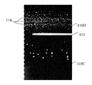
- FIG. 12 is a cross-sectional view of a connection flat plate viewed along line XII-XII in FIG. It is an image of a photograph showing cancer cells and experimental particles separated in a cell separation unit. It is an image of a photograph showing a cancer cell captured by a cell capture unit. It is a schematic diagram which shows the manufacturing process of the mold which manufactures the cell separation flow-path plate of a cell separation unit. It is a schematic diagram which shows the process of the back of FIG.
- FIG. 18 is a schematic view showing a step after Fig. 17; It is a schematic diagram which shows the produced mold. It is a schematic diagram which shows the process of manufacturing a cell separation flow-path plate with a mold. It is a schematic diagram which shows the process of adhering a cell separation flow-path plate to a cell separation lower plate.
- Fig. 5 is a schematic view showing a process of forming a cell capture well of a cell capture unit.
- FIG. 23 is a schematic view showing a step after FIG. 22.
- FIG. 24 is a schematic view showing a step after FIG. 23;
- FIG. 25 is a schematic view showing a step after FIG. 24.
- FIG. 5 is a schematic diagram showing cell capture wells formed on a cell capture plate.
- FIG. 6 is a schematic view showing the step of adhering a cell trapping channel plate to a cell trapping lower plate. It is a front view showing a cell capture device concerning a modification of an embodiment. It is a top view which shows the cell capture device of FIG. It is a perspective view which decomposes
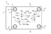
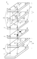
- the cell capture device 1 includes a plurality of stacked plates, specifically, a cell capture lower side plate 2, a cell capture flow path plate 3, and a connection plate. 4, a cell separation lower plate 5, a cell separation channel plate 6, and a cell separation upper plate 7 having a laminate structure.
- Fixing through holes 2 h are formed at the four corners of the cell capture lower plate 2.
- Fixing through holes 3 h are formed at the four corners of the cell trapping flow channel plate 3.
- fixing through holes 4h are formed.
- Fixing through holes 5 h are formed at the four corners of the cell separation lower plate 5.
- Fixing through holes 6 h are formed at the four corners of the cell separation flow channel plate 6.
- Fixing through holes 7 h are formed at four corners of the cell separation upper plate 7.
- the body of the pin 8 having the head 8a is inserted into the fixing through holes 2h, 3h, 4h, 5h, 6h and 7h, and is fixed to the external thread of the upper part of the pin 8.
- a nut 9 as a tool is attached.
- the cell capture lower side plate 2, the cell capture flow path plate 3, the connection plate 4, the cell separation lower side plate 5, the cell separation flow path plate 6, and the cell separation upper side plate 7 are integrated.
- the fixture is not limited to the nut 9 and may be another fixture.
- the cell separation lower plate 5, the cell separation channel plate 6, and the cell separation upper plate 7 constitute a plate-like cell separation unit 11.
- the fixing through holes 5 h, 6 h, 7 h constitute a fixing through hole 11 h of the cell separation unit 11.
- the cell capture lower side plate 2 and the cell capture flow path plate 3 constitute a plate-like cell capture unit 10 disposed below the cell separation unit 11 and fixed to the cell separation unit 11.
- the fixing through holes 2 h, 3 h, 4 h constitute a fixing through hole 10 h of the cell capture unit 10.
- the cell capture unit 10 is used to capture specific types of cells (eg, CTCs) at specific positions for analysis using the DEP action. Also, a cell capture unit 10 may be used to analyze captured cells.
- the cell separation unit 11 is used for pretreatment of the capture process. Specifically, the cell separation unit 11 separates cells of a specific type contained in a sample liquid (eg, blood) from other cells, and extracts liquid surrounding cells of a specific type from sample liquid components. It is used to replace the carrier fluid with a conductivity different from that of the cells.
- a specific type of cell captured by the cell capture unit 10 is referred to as a large cell, and other cells unnecessary for analysis are referred to as small cells.
- the cell separation unit 11 has a sample liquid inlet 7B, a carrier liquid inlet 7A, a cell separation channel 110, a large cell outlet 5C1, and a small cell outlet 7D.
- the sample liquid for example, blood
- the sample liquid injection device 15B for example, a pipette
- the sample solution contains a plurality of large cells, a plurality of small cells smaller than the large cells, and a sample liquid component.
- the carrier liquid is introduced into the carrier liquid inlet 7A from a carrier liquid injection device 15A (for example, a pipette).
- the carrier fluid has a conductivity that differs from that of the large cells and the sample fluid.
- the carrier solution may be a reagent solution for analyzing large cells in the cell capture unit 10.
- the flow of liquid is indicated by arrow F.
- the cell separation channel 110 is disposed horizontally, and the sample liquid from the sample liquid inlet 7B and the carrier liquid from the carrier liquid inlet 7A flow, and a set of a large cell and a carrier liquid, a set of small cells and a sample liquid component And separate.
- a set of large cells and a carrier liquid flows in from the cell separation channel 110 into the large cell outlet 5C1.
- the large cell outlet 5C1 guides the set of large cells and carrier fluid to the cell capture unit 10.
- a set of small cells and a sample liquid component flows from the cell separation channel 110 into the small cell outlet 7D.
- the set of small cells and sample liquid component is aspirated by the small cell and sample liquid component suction device 15D (for example, a tube connected to the suction pump P) and discharged from the small cell outlet 7D.
- the cell capture unit 10 has a large cell flow channel 100.
- the large cell flow channel 100 is arranged horizontally and leads to the large cell outlet 5C1 of the cell separation unit 11, where a set of large cells and a carrier liquid flows. While the carrier liquid flows through the large cell flow channel 100, large cells are captured, and the remaining carrier liquid is sucked and discharged by the carrier liquid suction device 15C (for example, a tube connected to the suction pump P). .
- the carrier liquid suction device 15C for example, a tube connected to the suction pump P.
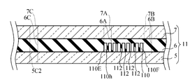
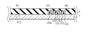
- the cell separation channel plate 6 is formed with a separation channel recess 110 h to be the cell separation channel 110.
- the cell separation lower plate 5 disposed below the cell separation channel plate 6 is stacked on the cell separation channel plate 6 to close the separation channel recess 110 h.
- the cell separation lower plate 5 and the cell separation channel plate 6 cooperate to define the cell separation channel 110.
- a sample liquid inlet 6B, a carrier liquid inlet 6A and a small cell outlet 6D are formed in the cell separation flow channel plate 6. These are holes passing through the upper wall of the separation channel recess 110 h.
- the sample liquid inlet 7B, the carrier liquid inlet 7A and the small cell outlet 7D are through holes formed in the cell separation upper plate 7, and the sample liquid inlet 6B, the carrier liquid inlet 6A and the small cells of the cell separation channel plate 6 respectively. Go to Exit 6D.
- the sample liquid flows into the cell separation channel 110 through the sample liquid inlets 7B and 6B.
- the carrier liquid flows into the cell separation channel 110 through the carrier liquid inlets 7A and 6A.
- the set of small cells and sample liquid component flows out of the cell separation channel 110 to the small cell outlets 6D, 7D.
- the large cell outlet 5C1 is a through hole formed in the cell separation lower side plate 5, and a set of large cells and a carrier liquid flows in from the cell separation channel 110 here.
- connection plate 4 is a gasket that connects the cell capture unit 10 and the cell separation unit 11 and reduces or prevents liquid leakage between the two.
- the connection plate 4 is formed with a large cell inflow through hole 4C1 and a carrier liquid inflow through hole 4C2.
- a large cell flow channel concave portion 100 h to be the large cell flow channel 100 is formed.
- the cell capture lower side plate 2 disposed below the cell capture flow path plate 3 is stacked on the cell capture lower side plate 2 to close the large cell flow path recess 100 h. In this way, the cell capture lower plate 2 and the cell capture plate 3 cooperate to define the large cell channel 100.
- an inlet hole 3C1 and an outlet hole 3C2 of the large cell flow channel 100 are formed. These are holes passing through the upper wall of the large cell flow passage recess 100 h.
- the inlet hole 3C1 passes through the large cell outlet 5C1 of the cell separation lower plate 5 and the large cell inflow through hole 4C1 of the connection plate 4.
- a set of large cells and a carrier liquid flows from the cell separation channel 110 into the large cell channel 100 via the large cell outlet 5C1, the large cell inflow through hole 4C1, and the inlet hole 3C1.
- the carrier liquid discharge through hole 5C2 is formed in the cell separation lower side plate 5
- the carrier liquid discharge through hole 6C is formed in the cell separation channel plate 6
- the carrier liquid discharge through hole is formed in the cell separation upper plate 7 7C is formed.
- These are in communication with each other, and constitute a carrier liquid discharge through hole 11C of the cell separation unit 11.
- the outlet hole 3C2 of the large cell flow channel 100 passes through the carrier liquid inflow through hole 4C2 of the connection plate 4 and the carrier liquid discharge through hole 11C of the cell separation unit 11.
- the carrier liquid is discharged from the large cell flow channel 100 through the outlet hole 3C2 and the carrier liquid inflow through holes 4C2, 5C2, 6C, 7C.
- the cell separation flow channel plate 6 and the cell capture flow channel plate 3 are formed of a transparent elastomer, for example, silicone rubber based on polydimethylsiloxane (PDMS).
- the cell separation upper plate 7 and the cell separation lower plate 5 are made of a transparent material such as acrylic resin or glass.
- the connection flat plate 4 is a plate formed of a transparent material such as acrylic resin or glass, for example, and an annular seal 4b1, 4b2 made of an elastomer is fixed to this plate.
- the annular seals 4b1 and 4b2 will be described later.
- the cell capture lower plate 2 has a substrate formed of a transparent material such as acrylic resin or glass, an electrode for DEP and an insulating layer. The electrode for DEP and the insulating layer will be described later.
- the cell separation channel 110 includes a linear main channel 111, a carrier liquid introduction channel 110A, a sample liquid introduction channel 110B, a large cell discharge channel 110C, and a small cell discharge channel. It has 110D.
- the carrier liquid introduction channel 110A is in communication with the carrier liquid inlet 6A
- the sample liquid inlet channel 110B is in communication with the sample liquid inlet 6B
- the large cell discharge channel 110C is in communication with the large cell outlet 5C1.
- the discharge channel 110D communicates with the small cell outlet 6D.
- the carrier liquid introduction channel 110A and the sample liquid introduction channel 110B are connected to one end (that is, the upstream end) of the main channel 111, and the large cell discharge channel 110C and the small cell discharge channel 110D are connected to the main channel 111. It is connected to the other end (that is, the downstream end).
- the carrier liquid introduction channel 110A and the large cell discharge channel 110C extend on the extension of the linear main channel 111 and have a large width, while the sample liquid introduction channel 110B and the small cell discharge flow In the passage 110D, only the portion near the main flow passage 111 extends on the extension of the main flow passage 111 and has a small width.
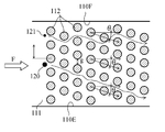
- a plurality of pillars 112 extending vertically are provided in the main channel 111 of the cell separation channel 110.
- These pillars 112 separate large cells and small cells flowing in a liquid by a deterministic lateral displacement (DLD) method.
- DLD deterministic lateral displacement
- the DLD method is a technology for separating large particles and small particles from a flow of liquid in which particles are dispersed, using a large number of columns regularly arranged in a microfluidic device.
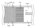
- FIG. 7 As shown in FIG. 7, it is a top view which shows many pillars 112 utilized by DLD method.
- the large number of columns 112 form a plurality of rows, each row being inclined at an angle ⁇ to the flow direction F.
- the small particles or small cells 121 travel in zigzag with respect to the flow direction F while changing the flow direction by the columns 112, but travel roughly linearly in a laminar flow.
- the large particles or large cells 120 travel obliquely along the inclination of the row of columns 112.
- these pillars 112 bias the flow of the large cells 120 to one side 110E of the cell separation channel 110 in the horizontal plane,
- the flow of the small cells 121 is directed in the longitudinal direction of the cell separation channel 110, that is, in the flow direction F in the horizontal plane.
- D C 1.4 g ⁇ N ⁇ 0.48
- g the distance between the columns 112 in the direction perpendicular to the flow direction F
- N the number of flow streams, and is expressed by the following equation.
- N 1 / ⁇ (equation 2)
- ⁇ the row shift fraction, that is, the shift ratio of the column 112
- ⁇ tan ⁇ .
- Boundary diameter D C obtained by the equation equivalent following Equation 1.
- D C 1.4 g ⁇ ⁇ 0.48 (Equation 3)
- the boundary diameter D C is in the range of the following equation. 0.3628 g ⁇ D C ⁇ 0.4636 g (Equation 4)
- Particles having a diameter less than the boundary diameter D C generally travel along the flow direction, and particles having a diameter greater than the boundary diameter D C travel diagonally. Because CTCs are larger than other blood cells, CTCs can be separated from the sample solution (eg, blood) by the cell separation unit 11 using the DLD method.
- the number and position of the pillars 112 are not necessarily accurate.
- the cross-sectional shape in the horizontal surface of the pillar 112 is circular, the cross-sectional shape may be another shape as long as the above-described separation action is exhibited.
- the carrier liquid inlets 7A, 6A and the large cell outlet 5C1 are in the horizontal plane on one side 110E (side where large cells concentrate) of the cell separation channel 110.
- the sample liquid inlets 7B and 6B and the small cell outlets 7D and 6D are disposed on the side, and are disposed on the opposite side 110F of the cell separation channel 110 in the horizontal plane.
- the carrier liquid introduced through the carrier liquid inlets 7A and 6A flows in the vicinity of one side 110E of the cell separation channel 110 by making the liquid flowing in the cell separation channel 110 a laminar flow, and the sample liquid inlet 7B
- the sample liquid component of the sample liquid introduced through the fluid flows around the other side 110 F of the cell separation channel 110.
- the large cells are concentrated in the vicinity of the side 110E of the cell separation channel 110, and small cells flow along the longitudinal direction of the cell separation channel 110.
- the carrier liquid inlet 7A and the large cell outlet 5C1 are automatically made large according to the flow of the liquid.
- the cells and the carrier liquid flow in, and the sample liquid inlet 7B and the small cell outlet 7D are disposed on the side of the other side 110F of the cell separation channel 110 in the horizontal plane, so that the liquid flows The small cell and the sample liquid component flow into the small cell outlet 7D, 6D automatically. Therefore, large cells and small cells can be easily separated, and at the same time large cells originally contained in the sample solution can be easily transferred to the carrier solution.
- a plurality of flow straightening plates 114 are disposed downstream of the main flow passage 111, and the flow straightening plates 114 are parallel to one another. And, it is arranged parallel to the longitudinal direction of the main flow path 111.
- a similar rectified version is also arranged upstream of the main channel 111.
- the rectifying plate 114 is not necessarily essential.
- reference numeral 113 denotes a partition between the small cell discharge channel 110D and the large cell discharge channel 110C, which is disposed on the downstream side of the rectifying plate 114.
- the large cell flow channel 100 of the cell capture unit 10 will be described in detail.
- a set of large cells and a carrier liquid flows from the cell separation channel 110 into the large cell channel 100 via the large cell outlet 5C1, the large cell inflow through hole 4C1, and the inlet hole 3C1.
- the large cell flow channel 100 is defined by the cell trapping lower plate 2 and the cell trapping flow channel plate 3.
- the cell capture lower plate 2 has a substrate 101 formed of a transparent material such as, for example, acrylic resin or glass.
- a plurality of electrode lines 102A and 102B are disposed parallel to each other on the upper surface of the substrate 101 of the cell capture lower plate 2 in order to attract the large cells 120 by the DEP action.
- the electrode lines 102A and 102B constitute inter-digitated electrodes (IDE, Inter-Digitated Electrodes). That is, the plurality of electrode lines 102A are connected by the electrode line 102C, and the plurality of electrode lines 102B are connected by the electrode line 102D.
- FIG. 9 is a schematic view and does not accurately represent the number of electrode lines 102A and 102B and the number of cell capture wells 104 described later. Different potentials are given to the electrode line 102C and the electrode line 102D by the power supply device 105.
- the electrode lines 102A and 102B are formed of ITO (Indium Tin Oxide), but may be formed of another conductive material.
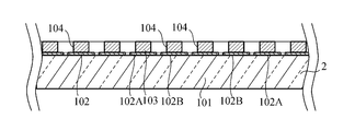
- the insulating layer 103 is formed on the electrode layer 102 having the electrode lines 102A and 102B, and the insulating layer 103 has a plurality of cells for capturing the large cells 120.
- a cell capture well 104 is formed.
- the cell capture well 104 is a circular through hole penetrating the insulating layer 103, but the shape of the cell capture well 104 is not limited to the illustration.
- the central portion of the cell capture well 104 does not overlap the electrode lines 102A and 102B, and each end of the cell capture well 104 overlaps any of the electrode lines 102A and 102B.
- Each cell capture well 104 has a diameter capable of capturing one of the large cells 120. That is, the diameter of the cell capture well 104 is larger than the diameter of the target large cell 120 and smaller than twice the diameter of the large cell 120.
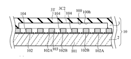
- the cell trapping channel plate 3 in which the large cell channel 100 is formed is formed of a soft elastomer, as shown in FIG. 10, the cell trapping channel plate 3 is compressed in the thickness direction to The gap between the upper wall 3T of the capture flow channel plate 3 and the substrate 101, that is, the height of the large cell flow channel 100 can be narrowed to accommodate each large cell 120 so as not to flow out into the cell capture well 104.
- the carrier liquid L may be a reagent liquid for analyzing the large cells 120 by the cell capture unit 10. Therefore, in the state shown in FIG. 10, the individual large cells 120 accommodated in the cell capture well 104 may be analyzed.
- a reagent solution containing a substance that emits fluorescence or phosphorescence in response to the components of the large cell 120 is used as the carrier liquid L, and fluorescence or phosphorescence emitted from individual large cells 120 accommodated in the cell capture well 104 is used. Changes may be observed.
- a reagent for observing the polymerase chain reaction may be used as the carrier solution L.
- the large cells 120 Prior to analysis of the large cells 120, the large cells 120 may be disrupted by applying a voltage to the large cells 120 by the electrode lines 102A and 102B, which is larger than the voltage used for cell capture.
- the reagent liquid may be introduced into the large cell flow channel 100, and thereafter, the individual large cells 120 stored in the cell capture well 104 may be analyzed.
- the reagent solution is introduced from, for example, the carrier liquid inlet 7A, as in the carrier liquid L, and the carrier liquid inlet 6A, the cell separation channel 110, the large cell outlet 5C1, the large cell inflow through hole 4C1, the inlet hole 3C1 , And through the large cell channel 100 to the large cell channel 100.
- the reagent liquid is discharged from the large cell flow path 100 through the outlet hole 3C2, the carrier liquid inflow through hole 4C2, and the carrier liquid discharge through hole 11C by the suction device 15C, similarly to the carrier liquid L.
- the cell capture channel plate 3, the connection plate 4, the cell separation lower plate 5, the cell separation channel plate 6, and the cell separation upper plate 7 above the large cell channel 100 are formed of a transparent material.
- the large cell flow channel 100 is disposed at a position different from the cell separation flow channel 110 in plan view. Therefore, it is easy to observe the large cells 120 fixed to the large cell flow channel 100 from above by visual observation or an optical instrument.
- the cell separation unit 11 and the connection plate 4 may be removed from the cell capture unit 10 before analyzing the large cells 120 immobilized in the large cell channel 100. This can be easily implemented by attaching and detaching the fixture, for example the nut 9, from the pin 8. Since the cell capture channel plate 3 above the large cell channel 100 is transparent, even after removing the cell separation unit 11 and the connection plate 4, the large cells 120 fixed to the large cell channel 100 can be viewed from above Or it is easy to observe with an optical instrument.
- connection plate 4 connecting the cell capture unit 10 and the cell separation unit 11 will be described in detail.
- the connection plate 4 is formed with a large cell inflow through hole 4C1 and a carrier liquid inflow through hole 4C2.
- the large cell inflow through hole 4C1 connects the large cell outlet 5C1 of the cell separation unit 11 and the large cell channel 100 of the cell capture unit 10, and the carrier liquid inflow through hole 4C2 is of the cell separation unit 11
- the carrier liquid discharge through hole 11C and the large cell flow path 100 of the cell capture unit 10 are connected.
- Annular seals 4b1 and 4b2 formed of an elastomer surrounding the large cell inflow through hole 4C1 and the carrier liquid inflow through hole 4C2 are fixed on the upper surface of the connection plate 4.
- the elastomer may, for example, be a silicone rubber.
- Annular seals 4b1 and 4b2 are disposed on the upper surface of the connection plate 4, ie, the surface of the cell separation unit 11 in contact with the lower cell separation plate 5, and the annular seals 4b1 and 4b2 are compressed and elastically deformed. Leakage of the carrier liquid between the cell separation unit 11 and the connection plate 4 is prevented or reduced.
- annular seals 4b1 and 4b2 are fixed to the connection plate 4, but the annular seals 4b1 and 4b2 may be separable from the connection plate 4.
- an annular seal such as an O-ring or a D-ring may be disposed between the connection plate 4 and the cell separation unit 11 as the annular seals 4b1 and 4b2.
- the cell capture device 1 has a laminate structure comprising a plurality of stacked plates.
- the elastomeric component reduces or prevents leakage from the fluid path.
- the cell separation channel plate 6 is formed of an elastomer. Therefore, when the cell separation channel plate 6 and the cell separation lower plate 5 are stacked and compressed, the cell separation channel plate 6 is in close contact with the cell separation lower plate 5, and the leakage of the liquid between them is prevented or reduced. Be done.
- the cell separation upper plate 7 and the cell separation channel plate 6 are stacked and compressed, the cell separation channel plate 6 is in close contact with the cell separation upper plate 7, and liquid leakage therebetween is prevented or reduced.
- the cell trapping channel plate 3 is formed of an elastomer, when the cell trapping channel plate 3 and the cell trapping lower plate 2 are overlapped and compressed, the cells on the cell trapping lower plate 2 The capture flow path plate 3 is in close contact and liquid leakage between them is prevented or reduced. Since the cell trapping channel plate 3 having the upper surface of the cell trapping unit 10 is formed of an elastomer, when the connecting plate 4 and the cell trapping unit 10 are stacked and compressed, the cell trapping unit 10 adheres to the connecting plate 4. Leakage of the carrier fluid between the cell capture unit 10 and the connection plate 4 is prevented or reduced. And, the leakage of the carrier liquid between the connection plate 4 and the cell separation unit 11 is prevented or reduced by the annular seal 4b1, 4b2 between them.
- elastomeric components reduce or prevent leakage from the liquid path.
- an adhesive, a chemical reaction, or a thermal reaction may be used to bond the plate to the plate.
- the spacing g of the columns 112 in the direction perpendicular to the flow direction F in the cell separation unit 11 is set to 40 ⁇ m, the number N of streamlines is 36.6, and the boundary diameter D C in the cell separation unit 11 according to the DLD method was designed to be 9.93 ⁇ m.
- a sample solution a solution prepared by adding 1 ⁇ l of 1.7 ⁇ m diameter spherical particles of polystyrene and PC3 cells (human prostate cancer cells) to 1000 ⁇ l of phosphate buffer was used. Spherical particles of polystyrene were used in place of platelets approximately 2 ⁇ m in diameter. Since the diameter of PC3 cells is about 12 to 22 ⁇ m, it was expected that the cell separation unit 11 having a boundary diameter D C of 9.93 ⁇ m could be separated from the spherical particles of polystyrene and thus platelets.
- Negative pressure was applied by the suction device 15C and the suction device 15D, and the flow rates of the carrier liquid and the sample liquid were controlled to 1.5 ⁇ l / min.
- the flow rates of the carrier liquid and the sample liquid were controlled to 1.5 ⁇ l / min.
- FIG. 13 is a photographic image showing spherical particles of PC3 cells and polystyrene separated by the cell separation unit 11 obtained in this experiment. It can be understood that the large cell PC3 cells flow into the large cell discharge flow channel 110C of the cell separation flow channel 110 and the spherical particles of polystyrene flow into the small cell discharge flow channel 110D.
- the set of spherical particles of polystyrene and the sample liquid component was discharged from the small cell outlet 7D, and the set of PC3 cells and the carrier liquid was sent to the cell trapping unit 10 through the large cell outlet 5C1.
- FIG. 14 is a photographic image showing PC3 cells captured by the cell capture unit 10 obtained in this experiment. Individual PC3 cells were captured in one cell capture well 104.
- the cell capture device 1 used in the above experiment will be described.
- the following manufacturing method is an example, and the cell capture device 1 may be manufactured by other methods.
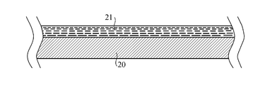
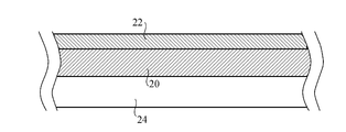
- an epoxy resin solution 21 was dropped on a P-type silicon wafer 20 (crystal orientation 100) with a diameter of 4 inches (100 mm) and homogenized by spin coating.
- a negative photoresist (trade name “SU8 3050”) manufactured by Nippon Kayaku Co., Ltd. was used. Spin coating was performed for 30 seconds at a rotational speed of 2000 rpm.
- the baking was performed for 25 minutes at a temperature of 95 ° C. using a heater 24 to form a dried epoxy resin layer 22.
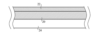
- the mask 26 was placed on the epoxy resin layer 22, and ultraviolet rays were irradiated using a mercury lamp to cure a desired portion of the epoxy resin layer 22.
- the mask 26 is used to form a portion corresponding to the cell separation channel 110 having the columns 112 of the cell separation channel plate 6 in a mold, and has a plurality of cylinders having the same size and the same shape as the plurality of columns 112.
- the cell separation channel plate 6 was molded.
- the procedure is as follows. First, the mold 28 was immersed in a mold release agent (trade name "NOX FREE F-350”) manufactured by Unimatec Co., Ltd. for 1 minute, and was sufficiently dried. Next, silicone rubber (trade name “SILPOT 184”) manufactured by Toray Dow Corning Co., Ltd. was injected into the mold 28, and left at a temperature of 100 ° C. for 1 hour to cure the silicone rubber. After that, the silicone rubber cured was peeled off from the mold 28 to obtain the cell separation flow channel plate 6 made of silicone rubber to which the shape of the mold 28 was transferred.
- a mold release agent trade name "NOX FREE F-350” manufactured by Unimatec Co., Ltd. for 1 minute
- silicone rubber trade name “SILPOT 184” manufactured by Toray Dow Corning Co., Ltd. was injected into the mold 28, and left at a temperature of 100 ° C. for 1 hour to cure the silicone rubber. After that, the silicone rubber cured was peeled off from
- the carrier liquid inlet 6A, the sample liquid inlet 6B, the small cell outlet 6D, and the fixing through hole 6h of the cell separation flow channel plate 6 may be formed thereafter. These molding resin protrusions may be formed on the mold 28 and formed by resin protrusions.
- the lower cell separation plate 5 made of glass and the cell separation channel plate 6 were joined.
- the procedure of bonding is as follows. First, a large cell outlet 5C1 having a diameter of 1 mm and a carrier liquid discharge through hole 5C2 were formed in the cell separation lower plate 5. Next, oxygen plasma was irradiated to the cell separation lower side plate 5 and the cell separation flow path plate 6 using an apparatus (trade name “RIE-10 NR”) of Samco Co., Ltd. The gas flow rate at this time was 50 SCCM, the pressure was 20 Pa, the RF output was 75 W, and the discharge time was 5 seconds. And the cell irradiation lower side plate 5 and the plasma irradiation surface of the cell separation flow path plate 6 were joined.
- the junction of the cell separation lower side plate 5 and the cell separation channel plate 6 is not necessarily essential. If the cell separation unit 11 is removed from the pin 8, it may be preferable not to join these, because cleaning, washing or drying of the cell separation channel 110 is easy.
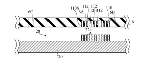
- an epoxy resin solution 31 was dropped on a substrate 101 on which ITO electrode wires 102A and 102B manufactured by Geomatec Co., Ltd. were formed, and the solution was made uniform by spin coating.
- a negative photoresist (trade name "SU 8 3005") manufactured by Nippon Kayaku Co., Ltd. was used. Spin coating was performed for 30 seconds at a rotational speed of 2000 rpm.
- pre-baking was performed for 25 minutes at a temperature of 95 ° C. using a heater 24 to form a dried epoxy resin layer 32.
- the mask 36 was placed on the epoxy resin layer 32, and ultraviolet rays were irradiated using a mercury lamp to cure a desired portion of the epoxy resin layer 32.
- the mask 36 is used to form the cell capture well 104 of the insulating layer 103 of the cell capture lower plate 2, and has a plurality of through holes of the same size and shape as the cell capture well 104.
- the cell trapping flow channel plate 3 formed of silicone rubber (trade name “SILPOT 184”) manufactured by Toray Dow Corning Co., Ltd. was joined to the cell trapping lower side plate 2.
- bonding of the cell trapping flow channel plate 3 and the cell trapping lower plate 2 is not necessarily essential. It may be preferable not to join them, since it is easy to clean, wash or dry the large cell channel 100 when the cell capture unit 10 is removed from the pin 8.
- connection plate 4 Next, a method of manufacturing the connection plate 4 will be described. First, the large cell inflow through hole 4C1 and the carrier liquid inflow through hole 4C2 were formed in a glass plate. Next, using screen printing, silicone rubber (trade name "KE-1935-A / B" manufactured by Shin-Etsu Chemical Co., Ltd., large cell inflow through hole 4C1 on the upper surface of connection plate 4 and carrier liquid inflow through hole The silicone rubber was applied to a thickness of 200 ⁇ m around 4 C 2. The silicone rubber is a material of the annular seals 4 b 1 and 4 b 2 and the inner diameter of the annular seals 4 b 1 and 4 b 2 was set to 1 mm. Then, the silicone rubber was cured.
- silicone rubber trade name "KE-1935-A / B” manufactured by Shin-Etsu Chemical Co., Ltd.
- the cell capture lower side plate 2, the cell capture flow path plate 3, the connection plate 4, the cell separation lower side plate 5, the cell separation flow path plate 6 and the cell separation upper side plate 7 prepared as described above were stacked.
- a plurality of pins 8 were inserted into the fixing through holes 11 h and 10 h to align the positions of these plates. Further, these plates were fixed by the nut 9 and the cell catching flow channel plate 3, the cell separation flow channel plate 6 and the annular seals 4b1 and 4b2 were appropriately compressed to seal the fluid path.
- the fixing through holes 11h and 10h may be formed before the lamination of the plates. However, it may be formed after laminating the plates and aligning their positions.
- the cell separation channel 110 of the cell separation unit 11 includes the set of the large cell and the carrier liquid, the small cell, and the sample liquid component from the introduced sample liquid and the carrier liquid. Separate the pair. Therefore, large cells and small cells can be easily separated, and at the same time large cells originally contained in the sample solution can be easily transferred to the carrier solution.
- the cell capture unit 10 fixed to the cell separation unit 11 receives a set of large cells and a carrier liquid. While the set of large cells and carrier liquid flows in the large cell flow channel 100 of the cell capture unit 10, a plurality of large cells are transferred to any one of the plurality of cell capture wells 104 of the cell capture unit 10 by dielectrophoretic action. It is captured. By integrating the cell separation unit 11 and the cell capture unit 10, it is possible to reduce contamination when transferring the large cell and carrier solution separated by the cell separation unit 11 to the cell capture unit 10. It is possible.
- the cell separation unit 11 and the cell capture unit 10 can be easily positioned by inserting the plurality of pins 8 into the fixing through holes 11 h and 10 h of the cell separation unit 11 and the cell capture unit 10.
- the cell separation unit 11 and the cell capture unit 10 can be easily integrated by the fixing device 9.
- the cell separation unit 11 or the cell capture unit 10 can be easily replaced.
- the cell separation unit 11 and the connection plate 4 may be removed from the cell capture unit 10 before analyzing the large cells 120 immobilized in the large cell channel 100.
- the cell separation unit 11 is disposed below the cell separation channel plate 6 in which the separation channel recess 110 h to be the cell separation channel 110 is formed, and the cell separation channel plate 6. And a cell separation lower plate 5 stacked on the cell separation channel plate 6 and closing the separation channel recess 110 h. Therefore, the cell separation flow is achieved by combining the cell separation flow path plate 6 in which the separation flow path recess 110 h is formed with the cell separation lower side plate 5 which is a simple plate even if the large cell outlet 5 C 1 is formed.
- the passage 110 can be easily formed.
- the cell separation flow channel plate 6 of the cell separation unit 11 is formed of a soft elastomer, it is easy to form the separation flow channel recess 110 h.
- the cell separation channel plate 6 is formed of an elastomer, when the cell separation channel plate 6 and the cell separation lower plate 5 are stacked and compressed, the cell separation channel plate 6 is formed on the cell separation lower plate 5. It adheres and liquid leakage between them is prevented or reduced.
- the cell separation unit 11 has the cell separation upper plate 7 disposed above the cell separation flow path plate 6 and stacked on the cell separation flow path plate 6, and the sample liquid inlet 7 B
- the carrier solution inlet 7A and the small cell outlet 7D penetrate the cell separation upper plate 7. Therefore, the cell separation channel plate 6 formed of a soft elastomer can be protected by the cell separation upper plate 7.
- the liquid injection device 15B or 15A or the liquid suction device 15D comes into contact with each of the sample liquid inlet 7B, the carrier liquid inlet 7A, and the small cell outlet 7D, so the sample liquid inlet 7B, the carrier liquid inlet 7A, By providing the small cell outlet 7D in the cell separation upper plate 7, the possibility that the cell separation channel plate 6 is damaged by the injection device 15B, 15A or the suction device 15D is prevented or reduced.
- the cell trapping unit 10 is disposed below the cell trapping flow path plate 3 and the cell trapping flow path plate 3 in which the large cell flow path concave portion 100 h to be the large cell flow path 100 is formed.
- the insulating layer 103 in which the electrode layer 102 having the plurality of electrode lines 102A and 102B and the plurality of cell trapping wells 104 are formed, while being stacked on the cell trapping channel plate 3 and closing the large cell channel recess 100h.
- the cell capture lower plate 2 is stacked.
- the cell trapping flow channel plate 3 of the cell trapping unit 10 is formed of a soft elastomer, it is easy to form the large cell flow channel concave portion 100h.
- the cell capture flow channel plate 3 can be compressed in the thickness direction to narrow the height of the large cell flow channel 100 so that each large cell can be stored so as not to flow out into the cell capture well 104.
- the cell trapping channel plate 3 is formed of an elastomer, when the cell trapping channel plate 3 and the cell trapping lower plate 2 are stacked and compressed, the cell trapping channel plate 3 is formed on the cell trapping lower plate 2. It adheres and liquid leakage between them is prevented or reduced.
- the cell separation unit 11 is formed with the sample liquid inlet 7B, the carrier liquid inlet 7A, the small cell outlet 7D, and the small cell outlet 7D. Since all of these ports are formed in the cell separation unit 11, a small area of the cell capture device 1 can be effectively utilized.
- the sample liquid injection device 15B, the carrier liquid injection device 15A, the small cell and sample liquid component suction device 15D, and the carrier liquid suction device 15C can be rapidly deployed.
- FIG. 28 and 29 show a cell capture device 1A according to a modification of the embodiment.
- FIG. 30 is an exploded top view of the cell capture device 1A.
- the large cell flow channel 100 is not shown in FIG. 29, and the cell capture unit 10 is not shown in FIG.
- the cell capture device 1A includes a sample liquid dilution unit 40 in addition to the configuration of the cell capture device 1 described above.
- the sample liquid dilution unit 40 is disposed above the cell separation unit 11.
- the sample liquid dilution unit 40 has stacked dilution unit lower flat plates (lower flat plates) 41, dilution flow channel plates (flow channel plates) 42, and dilution unit upper flat plates (upper flat plates) 43.
- the sample liquid dilution unit 40 is used for pretreatment of cell separation processing in the cell separation unit 11. Specifically, a sample stock solution (for example, blood) and a dilution liquid (for example, physiological saline) are introduced into the sample liquid dilution unit 40, and the sample liquid dilution unit 40 The mixed and reduced concentration sample liquid is supplied to the sample liquid inlet 7B of the cell separation unit 11.
- a sample stock solution for example, blood
- a dilution liquid for example, physiological saline
- the upper plate 43 is formed with a sample stock solution inlet 43B and a dilution solution inlet 43E, which are through holes, respectively.
- the sample stock solution is introduced into the sample stock solution inlet 43B from a sample liquid injection device 15B (for example, a pipette).
- Dilution fluid is introduced into the dilution fluid inlet 43E from a dilution fluid injection device 15E (for example, a pipette).
- a dilution channel recess (concave portion) 400h to be a dilution channel 400 is formed in the flow channel plate 42, and the lower flat plate 41 disposed below the flow channel plate 42 is superimposed on the flow channel plate 42. Thus, the recess 400 h is closed. Thus, the lower flat plate 41 and the flow channel plate 42 cooperate to define the dilution flow channel 400.
- the dilution channel 400 is arranged horizontally.
- a sample stock solution inlet 42B and a dilution solution inlet 42E are formed.
- the sample stock solution inlet 42B and the dilution solution inlet 42E are holes passing through the upper wall of the recess 400h and respectively pass through the sample stock solution inlet 43B and the dilution solution inlet 43E of the upper flat plate 43.
- the sample stock solution flows into the dilution channel 400 via the sample stock solution inlets 43B and 43B.
- the diluent flows into the dilution channel 400 via the diluent inlets 43E and 44E.
- the sample stock solution and the dilution solution flow and are mixed to generate a diluted sample solution having a uniform concentration.
- the lower flat plate 41 is formed with a sample liquid outlet 41 B which is a through hole.
- the diluted sample liquid flows from the dilution channel 400 into the sample liquid outlet 41B.
- the sample liquid outlet 41 B passes to the sample liquid inlet 7 B of the cell separation unit 11. Therefore, the mixed solution diluted as the sample solution flows into the cell separation channel 110 of the cell separation unit 11 from the sample solution inlet 7B.
- the sample liquid dilution unit 40 also has a function of transferring the carrier liquid to the cell separation unit 11 disposed below.
- the upper flat plate 43, the flow path plate 42, and the upper flat plate 43 are formed with through holes concentric with each other, and these through holes form a transport liquid inlet 40A vertically penetrating the sample liquid dilution unit 40.
- the carrier liquid is introduced into the carrier liquid inlet 40A from a carrier liquid injection device 15A (for example, a pipette).
- the carrier liquid inlet 40A passes through the carrier liquid inlet 7A of the cell separation unit 11. Therefore, the transport fluid flows into the cell separation channel 110 of the cell separation unit 11 from the transport fluid inlet 40A through the transport fluid inlet 7A.
- the sample liquid dilution unit 40 also has a function of transferring the set of small cells and sample liquid components separated by the cell separation unit 11 from the cell separation unit 11 upward.
- the upper flat plate 43, the flow channel plate 42, and the upper flat plate 43 are formed with through holes concentric with one another, and these through holes constitute a small cell outlet 40D vertically penetrating the sample liquid dilution unit 40.
- the small cell outlet 40D passes to the small cell outlet 7D of the cell separation unit 11.
- the set of small cells and sample liquid component is aspirated by the small cell and sample liquid component suction device 15D (for example, a tube connected to the suction pump P) and discharged from the small cell outlet 7D through the small cell outlet 40D. Ru.
- the sample liquid dilution unit 40 also has a function of transferring the remaining carrier liquid from which large cells have been removed by the cell capture unit 10 from the cell separation unit 11 upward.
- the upper flat plate 43, the flow path plate 42, and the upper flat plate 43 have through holes concentric with each other, and these through holes constitute a transport liquid discharge through hole 40C vertically penetrating the sample liquid dilution unit 40. Do.
- the carrier liquid discharge through hole 40 C passes through the carrier liquid discharge through hole 7 C of the cell separation unit 11 and thus the large cell flow channel 100 of the cell capture unit 10.
- the remaining carrier liquid from which large cells have been removed by the cell capture unit 10 is aspirated by the carrier liquid suction device 15C (for example, a tube connected to the suction pump P), and the carrier liquid is discharged from the carrier liquid discharge through hole 7C. It is discharged through the through hole 40C.
- the carrier liquid suction device 15C for example, a tube connected to the suction pump P
- the carrier liquid inlet 40A, the small cell outlet 40D, and the carrier liquid discharge through hole 40C are formed in the sample liquid dilution unit 40 disposed above the cell capture unit 10 and the cell separation unit 11. Since the sample stock solution inlet 42B and the dilution liquid inlet 42E are also formed in the sample liquid dilution unit 40, the small area of the cell capture device 1A can be effectively used. Further, for example, the sample liquid injection device 15B, the dilution liquid injection device 15E, the carrier liquid injection device 15A, the small cell and sample liquid component suction device 15D, and the carrier liquid suction device 15C can be rapidly deployed. .
- Fixing through holes concentric with one another are formed at the four corners of the upper flat plate 43, the flow path plate 42, and the upper flat plate 43, and these fixing through holes pass through the sample liquid dilution unit 40 for fixing.
- the through hole 40 h is configured.
- the body of the pin 8 inserted into the fixing through holes 2h, 3h, 4h, 5h, 6h, 7h is inserted into the fixing through hole 40h.
- a nut 9 as a fixture is attached to the upper male screw portion of the pin 8 so that the cell capture unit 10, the cell separation unit 11 and the sample liquid dilution unit 40 are integrated.
- the flow path plate 42 is formed of a transparent elastomer, for example, a silicone rubber based on PDMS.
- the upper flat plate 43 and the lower flat plate 41 are made of, for example, a transparent material such as acrylic resin or glass.
- the flow path plate 42 adheres to the lower flat plate 41. Liquid leakage between them is prevented or reduced, and the upper flat plate 43 is in close contact with the flow path plate 42, and liquid leakage therebetween is prevented or reduced.
- annular seals 44A, 44B, 44C and 44D made of elastomer are fixed.
- the annular seals 44A, 44B, 44C, 44D may be the same as the annular seals 4b1, 4b2.
- Annular seals 44A, 44B, 44C, and 44D surround the carrier liquid inlet 7A, the sample liquid inlet 7B, the carrier liquid discharge through hole 7C, and the small cell outlet 7D, respectively.
- Annular seals 44A, 44B, 44C, 44D are disposed on the upper surface of the cell separation upper plate 7, that is, the surface contacting the lower plate 41 of the sample liquid dilution unit 40, and the annular seals 44A, 44B, 44C, 44D By compression and elastic deformation, the leakage of the carrier liquid between the cell separation unit 11 and the sample liquid dilution unit 40 is prevented or reduced.
- annular seals 44A, 44B, 44C, 44D are fixed to the cell separation upper plate 7, but the annular seals 44A, 44B, 44C, 44D may be separable from the cell separation upper plate 7.
- annular seal such as an O-ring or a D-ring may be disposed between the cell separation upper plate 7 and the sample liquid dilution unit 40 as the annular seals 44A, 44B, 44C, 44D.
- the sample liquid dilution unit 40 is transparent, and the liquid flow in the sample liquid dilution unit 40 and the cell separation unit 11 and the state of the liquid flow or particles in the cell capture unit 10 are recognized from above by visual observation or optical instrument It is easy to do.
- the dilution channel 400 has an inlet path leading to the sample stock solution inlet 42B, an inlet path leading to the diluent inlet 42E, a main path leading to these inlet paths, a main path and a sample liquid outlet 41B.
- Have an exit path connecting The main path is bent in a zigzag.
- the sample fluid diluted by the sample fluid dilution unit 40 can be supplied to the cell separation unit 11. Therefore, clogging of liquid in the flow path in the cell separation unit 11 and the cell capture unit 10 can be prevented or reduced.
- the zigzag main path of the dilution flow path 400 contributes to the thorough mixing of the sample stock solution and the dilution liquid to make the concentration of the sample liquid uniform.
- a mold for manufacturing the flow channel plate 42 is generated by a method similar to the method shown in FIGS.
- the mold has a silicon wafer 20 and a residual resin protrusion, and the residual resin protrusion corresponds to the dilution channel 400, the sample stock solution inlet 42B and the diluent inlet 42E.
- a flow path plate 42 made of silicone rubber is obtained.
- the lower flat plate 41 made of glass and the flow path plate 42 may be joined.
- the cell capture device 1 of the above embodiment is used to separate and capture cancer cells in a sample solution from small cells, but may be used to separate cells other than cancer cells. Good.
- cell separation unit 11 of cell capture device 1 to separate red blood cells from smaller platelets, or white blood cells from smaller platelets, use cell separation unit 11 of cell capture device 1 and separate separated red blood cells or white blood cells in cell capture unit 10. It may be captured.
- the cell separation upper plate 7 of the cell separation unit 11 is provided to protect the cell separation channel plate 6 made of soft elastomer.
- the cell separation upper plate 7 is not necessarily essential.
- connection plate 4 which is a gasket between the cell separation unit 11 and the cell capture unit 10 in the above embodiment is not necessarily essential.
- the cell capture channel plate 3 of the cell separation unit 11 is formed of an elastomer, and by overlapping and compressing it on the cell separation lower plate 5 of the cell capture unit 10, liquid leakage between them is prevented or Reduced. Furthermore, in order to improve the sealing of the flow path between the two, as shown in FIG. 31, even if the annular seals 4b1 and 4b2 are disposed between the cell trapping flow channel plate 3 and the cell separation lower plate 5 Good. In this case, the annular seals 4b1 and 4b2 may be fixed to or separated from either the cell capture flow channel plate 3 or the cell separation lower plate 5.
- the cell trapping flow channel plate 3, the connection plate 4, the cell separation lower side plate 5, the cell separation flow channel plate 6 and the cell separation upper surface plate 7 of the embodiment of FIG. 1 described above are formed of a transparent material. Further, the cell trapping flow channel plate 3, the cell separation lower side plate 5, the cell separation flow channel plate 6 and the cell separation upper plate 7 of the modification of FIG. 31 are formed of a transparent material. For this reason, it is easy to recognize the state of the flow or the particles of the liquid in the large cell flow channel 100 and the cell separation flow channel 110 from above by visual observation or an optical instrument. However, it is not necessary that all of them be transparent, and it is preferable if at least a portion above the cell separation flow channel plate 6 and at least a portion above the cell capture well 104 are transparent.
- FIGS. 8 to 10 different potentials are applied to the electrode lines 102A and 102B disposed on the same plane of the cell capturing unit 10 according to the above embodiment, and an electric field is applied to the transport liquid L in the lateral direction.
- an electrode 106 facing the electrode wires 102A and 102B may be provided on the lower surface of the upper wall 3T of the cell trapping flow channel plate 3.
- the same potential is applied to the electrode lines 102A and 102B, a different potential is applied to the electrode 106, and an electric field acts on the transport liquid L in the vertical direction.
- the cell separation unit is A sample liquid inlet into which a sample liquid containing a plurality of large cells, a plurality of small cells smaller than the large cells, and a sample liquid component is introduced; A carrier liquid inlet into which a carrier liquid having a conductivity different from that of the large cells is introduced; The sample liquid from the sample liquid inlet and the carrier liquid from the carrier liquid inlet flow horizontally, and a set of the large cells and the carrier liquid, a set of the small cells and the sample liquid component, and the like.
- a cell separation channel for separating A large cell outlet through which the large cells and the carrier liquid flow from the cell separation channel; A small cell outlet through which the small cells and the set of sample liquid components flow from the cell separation channel;
- the cell capture unit is A large cell flow path disposed horizontally and communicating with the large cell outlet of the cell separation unit, and through which a set of the large cell and the carrier liquid flows; And a plurality of electrode lines for attracting the large cells flowing through the large cell flow channel by dielectrophoresis.
- a cell capture device characterized in that a plurality of cell capture wells each having a size capable of capturing one of the large cells attracted by the electrode wire are formed in the large cell flow channel.
- Each of the cell separation channels extends vertically inside, and the flow of the large cells is biased to one side of the cell separation channel in the horizontal plane, and the flow of the small cells is in the horizontal plane.
- a plurality of columns are provided, oriented in the longitudinal direction of the cell separation channel, The carrier liquid inlet and the large cell outlet are disposed on the side of the one side of the cell separation channel in a horizontal plane, The cell capture device according to claim 1, wherein the sample liquid inlet and the small cell outlet are disposed on the other side of the cell separation channel in a horizontal plane.
- the carrier liquid introduced through the carrier liquid inlet flows near the one side of the cell separation channel and is introduced through the sample liquid inlet
- the sample liquid component of the sample liquid flows near the other side of the cell separation channel.
- sample fluid inlet and the small cell outlet are arranged on the other side of the cell separation channel in the horizontal plane so that the small cell outlet is automatically moved to the small cell outlet as the liquid flows. And sample liquid components flow in. Therefore, large cells and small cells can be easily separated, and at the same time large cells originally contained in the sample solution can be easily transferred to the carrier solution.
- a plurality of fixing through holes are formed in the cell separation unit, A plurality of fixation through holes are formed in the cell capture unit, The fixing through hole of the cell separation unit, and a plurality of pins inserted into the fixing through hole of the cell capturing unit;
- the cell capture device according to clause 1 or 2 further comprising: a plurality of fixtures attached to the pins to fix the cell separation unit and the cell capture unit.
- the cell separation unit and the cell capture unit can be easily positioned by inserting a plurality of pins into the fixation through holes of the cell separation unit and the cell capture unit, and the cell separation unit can be fixed by the fixture.
- the cell capture unit can be easily integrated. Also, cell separation units or cell capture units can be easily replaced.
- the cell separation unit is A cell separation channel plate in which a separation channel concave portion to be the cell separation channel is formed; A cell separation lower plate disposed below the cell separation flow path plate and stacked on the cell separation flow path plate to close the separation flow path recess; The cell trapping device according to any one of Items 1 to 3, wherein the large cell outlet penetrates the cell separation lower plate.
- the cell separation flow path is formed by combining the cell separation flow path plate in which the separation flow path recess is formed with the cell separation lower side plate, which is a simple plate even if the large cell outlet is formed. Can be easily formed.
- the cell separation channel plate is formed of a soft elastomer, it is easy to form the separation channel recess. Further, since the cell separation channel plate is formed of an elastomer, when the cell separation channel plate and the cell separation lower plate are stacked and compressed, the cell separation channel plate adheres to the cell separation lower plate, Fluid leakage is prevented or reduced.
- the cell separation unit further includes a cell separation upper plate disposed above the cell separation channel plate and stacked on the cell separation channel plate; 5.
- the cell separation channel plate formed of a soft elastomer can be protected by the cell separation upper plate.
- Each of the sample liquid inlet, the carrier liquid inlet, and the small cell outlet is in contact with a liquid injector or a liquid suction device, so that the sample liquid inlet, the carrier liquid inlet, and the small cell outlet are separated from the cell separation top plate.
- the cell capture unit is A cell capture flow channel plate in which a large cell flow channel concave portion to be the large cell flow channel is formed;
- the electrode layer having the plurality of electrode lines and the plurality of cell trapping wells are disposed below the cell trapping channel plate and stacked on the cell trapping channel plate to close the large cell channel recess, and
- the cell trap channel plate is formed of a soft elastomer, it is easy to form a large cell channel recess.
- the cell trap channel plate can be compressed in the thickness direction to narrow the height of the large cell channel so that each large cell can be stored so as not to flow out into the cell trap well.
- the cell trapping channel plate is formed of an elastomer, when the cell trapping channel plate and the cell trapping lower plate are stacked and compressed, the cell trapping channel plate is in close contact with the cell trapping lower plate. Fluid leakage is prevented or reduced.
- a large cell inflow through hole is disposed between the cell separation unit and the cell capture unit, and connects the large cell outlet of the cell separation unit and the large cell flow path of the cell capture unit. Further equipped with a connection plate, An annular seal formed of an elastomer, which is in contact with the cell separation unit, is disposed on the upper surface of the connection plate, the annular seal surrounding the large cell inflow through hole, any one of the items 1 to 8 The cell capture device as described in.
- the annular seal is disposed on the upper surface of the connection plate disposed between the cell separation unit and the cell capture unit to prevent the leakage of the carrier liquid between the cell separation unit and the connection plate or Reduced. Furthermore, in this case, when the top surface of the cell capture unit is formed of an elastomer, the cell capture unit adheres to the connection plate, so that the leakage of the carrier liquid between the cell capture unit and the connection plate is prevented or reduced. Ru.
- the cell separation unit is formed with a carrier liquid discharge through hole which is in communication with the large cell flow channel of the cell capture unit and from which the carrier liquid is discharged from the large cell flow channel.
- a carrier fluid discharge through hole is formed in the cell separation unit disposed above the cell capture unit. Since the cell separation unit is also formed with the sample liquid inlet, the carrier liquid inlet, and the small cell outlet, a small area can be effectively used.
- a large cell inflow through hole is disposed between the cell separation unit and the cell capture unit, and connects the large cell outlet of the cell separation unit and the large cell flow path of the cell capture unit.
- a connection plate having a carrier liquid inflow through hole connecting the carrier liquid discharge through hole of the cell separation unit and the large cell flow path of the cell capture unit,
- An annular seal formed of an elastomer is disposed on the upper surface of the connection plate so as to surround the large cell inflow through hole and the carrier liquid inflow through hole, respectively, and contact the cell separation unit.
- the annular seal is disposed on the upper surface of the connection plate disposed between the cell separation unit and the cell capture unit to prevent the leakage of the carrier liquid between the cell separation unit and the connection plate or Reduced. Furthermore, in this case, when the top surface of the cell capture unit is formed of an elastomer, the cell capture unit adheres to the connection plate, so that the leakage of the carrier liquid between the cell capture unit and the connection plate is prevented or reduced. Ru.
- the cell separation unit further comprises a plate-like sample liquid dilution unit disposed above the cell separation unit and fixed to the cell separation unit.
- the sample liquid dilution unit is A sample stock solution inlet into which the sample stock solution is introduced; A dilution fluid inlet into which the dilution fluid is introduced; A dilution flow path disposed horizontally, wherein the sample stock solution from the sample stock solution inlet and the dilution liquid from the dilution liquid inlet flow, and the sample stock solution and the dilution liquid are mixed to form the sample liquid; And a sample liquid outlet through which the sample liquid flows from the dilution channel;
- the cell capture device according to any one of Items 1 to 13, wherein the sample liquid outlet is in communication with the sample liquid inlet of the cell separation unit.
- the sample fluid diluted by the sample fluid dilution unit can be supplied to the cell separation unit. Therefore, clogging of the fluid in the flow path in the cell separation unit and the cell capture unit can be prevented or reduced.
- the sample stock solution and the dilution solution can be sufficiently mixed to make the concentration of the sample solution uniform.
- the sample liquid dilution unit is A carrier liquid inlet, which is a through hole which is in communication with the carrier liquid inlet of the cell separation unit and into which the carrier liquid is introduced;
- a small cell outlet which is a through-hole which is in communication with the small cell outlet of the cell separation unit and through which a set of the small cell and the sample liquid component is discharged;
- the carrier liquid discharge through hole which is a through hole which is in communication with the large cell flow channel of the cell trapping unit and through which the carrier liquid is discharged from the large cell flow channel;
- the cell trapping device as described.
- the carrier liquid inlet, the small cell outlet, and the carrier liquid discharge through-hole are formed in the sample liquid dilution unit disposed above the cell capture unit and the cell separation unit.
- the sample liquid dilution unit is also formed with a sample stock solution inlet and a dilution liquid inlet, so that a small area of the cell capture device can be effectively utilized.
- the sample liquid dilution unit is A dilution flow passage plate in which a dilution flow passage concave portion to be the dilution flow passage is formed; A dilution unit lower flat plate disposed below the dilution flow channel plate and stacked on the dilution flow channel plate to close the dilution flow channel recess; A dilution unit upper plate disposed above the dilution flow channel plate and having the sample stock solution inlet and the dilution liquid inlet; The sample solution outlet penetrates the dilution unit lower plate,
- the cell trapping device according to any one of clauses 14 to 16, wherein the dilution flow channel plate is formed of an elastomer.
- the dilution channel plate is formed of a soft elastomer, it is easy to form the separation channel recess. Further, since the dilution channel plate is formed of an elastomer, when the dilution unit upper plate, the dilution channel plate and the dilution unit lower plate are stacked and compressed, the dilution channel plate on the dilution channel upper plate and the dilution unit lower side The plates are in intimate contact and liquid leakage between them is prevented or reduced.
- An annular seal formed of an elastomer is disposed on the top surface of the cell separation unit, the annular seal surrounding the sample liquid inlet and in contact with the sample liquid dilution unit.
Abstract
A cell capturing device is provided with a flat-plate-like cell separation unit and a flat-plate-like cell capture unit arranged below the cell separation unit. In a cell separation flow path in the cell separation unit, a sample solution and a carrier liquid flow. The sample solution contains multiple large cells, multiple small cells, and a sample liquid component. The cell separation flow path can separate a fraction containing the large cells and the carrier liquid from a fraction containing the small cells and the sample liquid component. The cell capture unit is provided with a large cell flow path through which the fraction containing the large cells and the carrier liquid flows and multiple electrode wires for drawing the large cells by a dielectrophoretic action. In the large cell flow path, multiple cell capture wells are formed, each of which has such a size that one of the large cells drawn by the electrode wires can be captured by each of the cell capture wells.
Description
本発明は、サンプル液から特定の細胞を選択的に分離し、これらの細胞を解析のために捕捉する細胞捕捉装置に関する。
The present invention relates to a cell capture device that selectively isolates specific cells from sample fluid and captures these cells for analysis.
がん患者の血液中には、がん原発組織から剥離した血中循環腫瘍細胞(CTC、Circulating Tumor Cell)が存在する。このCTCは、がんの転移と関連していると考えられており、血液中のCTCを解析することで、がんの早期発見や、転移予測が行えると期待できる。しかし、CTCはがん患者の10億個の細胞に数個程度と非常に希少であり、その解析は困難を極める。一方、個々のCTCは、異なる性質を有すると考えられており、単一のCTCをそれぞれ解析することが望ましい。
In blood of cancer patients, circulating tumor cells (CTC, Circulating Tumor Cell) exfoliated from cancer primary tissue are present. This CTC is considered to be associated with cancer metastasis, and analyzing CTC in blood can be expected to enable early detection of cancer and metastasis prediction. However, CTCs are very rare, as few as one billion cells of cancer patients, and their analysis is extremely difficult. On the other hand, individual CTCs are considered to have different properties, and it is desirable to analyze each single CTC.
これまでに、液体中の目的とする複数の細胞を誘電泳動(DEP、Dielectrophoresis)作用によって引き付けて、多数のマイクロウェルまたはマイクロチャンバーのいずれか複数に、これらの細胞をそれぞれ捕捉することで、細胞を解析する装置が提案されている(特許文献1,2、非特許文献1)。
So far, cells of interest are attracted by the dielectrophoresis (DEP, Dielectrophoresis) action, and the cells are captured respectively in any of a plurality of microwells or microchambers. An apparatus for analyzing is proposed ( patent documents 1 and 2, non-patent document 1).
しかしながら、誘電泳動作用を利用して、個々のCTCを捕捉するためには、例えば、遠心分離を用いた血液からのCTC分離、誘電泳動のための液体の交換といった前処理を行う必要がある。液体の交換を行う理由は、通常の血液の導電率がCTCのそれとほぼ同じであるため、誘電泳動が困難だからである。これらの前処理には熟練の技術が必要である。また、CTCを分離したとしても、CTCの捕捉処理の前に、CTCが汚染されるおそれがあり、そのために解析結果への悪影響が懸念される。
However, in order to capture individual CTCs using dielectrophoresis, for example, it is necessary to perform pretreatment such as CTC separation from blood using centrifugation and exchange of liquid for dielectrophoresis. The reason for performing the fluid exchange is that dielectrophoresis is difficult because the conductivity of normal blood is about the same as that of CTC. These pretreatments require skilled techniques. In addition, even if CTCs are separated, CTCs may be contaminated prior to CTC capture processing, which may adversely affect analysis results.
CTCの捕捉に関する課題を説明したが、他の細胞よりも大きいサイズを有する他の種類の大細胞の捕捉に関しても類似する課題がある。
Although the problem with capturing CTCs has been described, there is a similar problem with capturing other types of large cells that are larger in size than other cells.
そこで、本発明は、サンプル液に含まれていた大細胞をサンプル液から容易に分離することができ、大細胞を容易に搬送液に移すことができ、大細胞と搬送液の組を細胞捕捉処理のために移動する際の汚染を低減することが可能な細胞捕捉装置を提供する。
Therefore, according to the present invention, large cells contained in the sample solution can be easily separated from the sample solution, large cells can be easily transferred to the carrier solution, and a combination of large cells and carrier solution can be captured by cells. Provided is a cell capture device capable of reducing contamination when moving for processing.
本発明のある態様に係る細胞捕捉装置は、平板状の細胞分離ユニットと、前記細胞分離ユニットの下方に配置されて前記細胞分離ユニットに固定された平板状の細胞捕捉ユニットとを備え、前記細胞分離ユニットは、複数の大細胞と、前記大細胞よりも小さい複数の小細胞と、サンプル液体成分とを含むサンプル液が導入されるサンプル液入口と、前記大細胞の導電率と異なる導電率を有する搬送液が導入される搬送液入口と、水平に配置され、前記サンプル液入口からの前記サンプル液および前記搬送液入口からの前記搬送液が流れるとともに、前記大細胞と前記搬送液の組と、前記小細胞と前記サンプル液体成分の組とを分離する細胞分離流路と、前記細胞分離流路から前記大細胞と前記搬送液の組が流入する大細胞出口と、前記細胞分離流路から前記小細胞と前記サンプル液体成分の組が流入する小細胞出口とを有し、前記細胞捕捉ユニットは、水平に配置され、前記細胞分離ユニットの前記大細胞出口に通じており、前記大細胞と前記搬送液の組が流れる大細胞流路と、前記大細胞流路を流れる前記大細胞を誘電泳動作用により引き付けるための複数の電極線とを有しており、前記大細胞流路には、前記電極線で引き付けられた前記大細胞の1つを各々が捕捉可能な大きさを有する複数の細胞捕捉ウェルが形成されている。
A cell capture device according to an aspect of the present invention comprises a flat cell separation unit, and a flat cell capture unit disposed below the cell separation unit and fixed to the cell separation unit, the cells The separation unit has a conductivity different from the conductivity of the large cells, a sample liquid inlet into which a sample liquid containing a plurality of large cells, a plurality of small cells smaller than the large cells, and a sample liquid component is introduced. And the sample liquid from the sample liquid inlet and the carrier liquid from the carrier liquid inlet flow in parallel with the carrier liquid inlet into which the carrier liquid is introduced, and a set of the large cells and the carrier liquid A cell separation channel separating the small cells and the set of sample liquid components; a large cell outlet through which the large cells and the carrier liquid flow from the cell separation channel; and the cells The small cell and the small cell outlet through which the set of the sample liquid component flows from the separation channel, and the cell capture unit is disposed horizontally and communicates with the large cell outlet of the cell separation unit; A large cell flow channel through which the large cells and the carrier liquid flow, and a plurality of electrode lines for attracting the large cells flowing through the large cell flow channel by dielectrophoresis; The channel is formed with a plurality of cell capture wells each having a size capable of capturing one of the large cells attracted by the electrode lines.
この態様においては、細胞分離ユニットの細胞分離流路が、導入されたサンプル液と搬送液から、大細胞と搬送液の組と、小細胞とサンプル液体成分の組とを分離する。したがって、大細胞と小細胞を容易に分離することができると同時に、元々、サンプル液に含まれていた大細胞を搬送液に容易に移すことができる。細胞分離ユニットに固定された細胞捕捉ユニットは、大細胞と搬送液の組を受ける。細胞捕捉ユニットの大細胞流路を大細胞と搬送液の組が流れる間に、誘電泳動作用によって、複数の大細胞が細胞捕捉ユニットの複数の細胞捕捉ウェルのいずれか複数にそれぞれ捕捉される。細胞分離ユニットと細胞捕捉ユニットが一体化されていることによって、細胞分離ユニットで分離された大細胞と搬送液の組を、細胞捕捉ユニットに移動する際の汚染を低減することが可能である。
In this aspect, the cell separation channel of the cell separation unit separates the set of large cells and carrier liquid and the set of small cells and sample liquid components from the introduced sample liquid and carrier liquid. Therefore, large cells and small cells can be easily separated, and at the same time large cells originally contained in the sample solution can be easily transferred to the carrier solution. The cell capture unit immobilized on the cell separation unit receives a set of large cells and carrier fluid. While the large cell and the carrier solution are flowing through the large cell flow channel of the cell capture unit, a plurality of large cells are respectively captured by any of the plurality of cell capture wells of the cell capture unit by dielectrophoretic action. By integrating the cell separation unit and the cell capture unit, it is possible to reduce the contamination when transferring the large cells separated in the cell separation unit and the carrier liquid to the cell capture unit.
以下、添付の図面を参照しながら本発明に係る実施形態を説明する。図面においては、部分の特徴を強調して示すことがあるため、縮尺は必ずしも正確ではない。
Hereinafter, embodiments according to the present invention will be described with reference to the attached drawings. The drawings are not necessarily to scale, as the features of the parts may be highlighted.
図1および図3に示すように、この実施形態に係る細胞捕捉装置1は、重ね合わせられた複数の板、具体的には、細胞捕捉下側平板2、細胞捕捉流路板3、接続平板4、細胞分離下側平板5、細胞分離流路板6、および細胞分離上側平板7を備える積層体構造を有する。
As shown in FIG. 1 and FIG. 3, the cell capture device 1 according to this embodiment includes a plurality of stacked plates, specifically, a cell capture lower side plate 2, a cell capture flow path plate 3, and a connection plate. 4, a cell separation lower plate 5, a cell separation channel plate 6, and a cell separation upper plate 7 having a laminate structure.
細胞捕捉下側平板2の四隅には、固定用貫通孔2hが形成されている。細胞捕捉流路板3の四隅には、固定用貫通孔3hが形成されている。接続平板4の四隅には、固定用貫通孔4hが形成されている。細胞分離下側平板5の四隅には、固定用貫通孔5hが形成されている。細胞分離流路板6の四隅には、固定用貫通孔6hが形成されている。細胞分離上側平板7の四隅には、固定用貫通孔7hが形成されている。
Fixing through holes 2 h are formed at the four corners of the cell capture lower plate 2. Fixing through holes 3 h are formed at the four corners of the cell trapping flow channel plate 3. At four corners of the connection plate 4, fixing through holes 4h are formed. Fixing through holes 5 h are formed at the four corners of the cell separation lower plate 5. Fixing through holes 6 h are formed at the four corners of the cell separation flow channel plate 6. Fixing through holes 7 h are formed at four corners of the cell separation upper plate 7.
図1に示すように、固定用貫通孔2h,3h,4h,5h,6h,7hには、頭部8aを有するピン8の胴部が挿入され、ピン8の上部のオネジ部には、固定具としてのナット9が取り付けられている。このようにして、細胞捕捉下側平板2、細胞捕捉流路板3、接続平板4、細胞分離下側平板5、細胞分離流路板6、および細胞分離上側平板7が一体化されている。但し、固定具はナット9に限定されず、他の固定具であってもよい。
As shown in FIG. 1, the body of the pin 8 having the head 8a is inserted into the fixing through holes 2h, 3h, 4h, 5h, 6h and 7h, and is fixed to the external thread of the upper part of the pin 8. A nut 9 as a tool is attached. Thus, the cell capture lower side plate 2, the cell capture flow path plate 3, the connection plate 4, the cell separation lower side plate 5, the cell separation flow path plate 6, and the cell separation upper side plate 7 are integrated. However, the fixture is not limited to the nut 9 and may be another fixture.
細胞分離下側平板5、細胞分離流路板6、および細胞分離上側平板7は、平板状の細胞分離ユニット11を構成する。固定用貫通孔5h,6h,7hは、細胞分離ユニット11の固定用貫通孔11hを構成する。
The cell separation lower plate 5, the cell separation channel plate 6, and the cell separation upper plate 7 constitute a plate-like cell separation unit 11. The fixing through holes 5 h, 6 h, 7 h constitute a fixing through hole 11 h of the cell separation unit 11.
細胞捕捉下側平板2および細胞捕捉流路板3は、細胞分離ユニット11の下方に配置されて細胞分離ユニット11に固定された平板状の細胞捕捉ユニット10を構成する。固定用貫通孔2h,3h,4hは、細胞捕捉ユニット10の固定用貫通孔10hを構成する。
The cell capture lower side plate 2 and the cell capture flow path plate 3 constitute a plate-like cell capture unit 10 disposed below the cell separation unit 11 and fixed to the cell separation unit 11. The fixing through holes 2 h, 3 h, 4 h constitute a fixing through hole 10 h of the cell capture unit 10.
細胞捕捉ユニット10は、DEP作用を利用して、特定の種類の細胞(例えばCTC)を解析のために特定の位置にそれぞれ捕捉するために使用される。また、捕捉された細胞を解析するために、細胞捕捉ユニット10を使用してもよい。
The cell capture unit 10 is used to capture specific types of cells (eg, CTCs) at specific positions for analysis using the DEP action. Also, a cell capture unit 10 may be used to analyze captured cells.
細胞分離ユニット11は、捕捉処理の前処理のために使用される。具体的には、細胞分離ユニット11は、サンプル液(例えば血液)に含まれていた特定の種類の細胞を他の細胞から分離し、かつ特定の種類の細胞の周囲の液体をサンプル液体成分から細胞の導電率と異なる導電率を有する搬送液に交換するために使用される。以下、細胞捕捉ユニット10で捕捉される特定の種類の細胞を大細胞と呼び、解析に不要な他の細胞を小細胞と呼ぶ。
The cell separation unit 11 is used for pretreatment of the capture process. Specifically, the cell separation unit 11 separates cells of a specific type contained in a sample liquid (eg, blood) from other cells, and extracts liquid surrounding cells of a specific type from sample liquid components. It is used to replace the carrier fluid with a conductivity different from that of the cells. Hereinafter, a specific type of cell captured by the cell capture unit 10 is referred to as a large cell, and other cells unnecessary for analysis are referred to as small cells.
図1から図3に示すように、細胞分離ユニット11は、サンプル液入口7B、搬送液入口7A、細胞分離流路110、大細胞出口5C1、および小細胞出口7Dを有する。サンプル液入口7Bには、サンプル液の注入装置15B(例えばピペット)から、サンプル液(例えば血液)が導入される。サンプル液は、複数の大細胞と、大細胞よりも小さい複数の小細胞と、サンプル液体成分とを含む。搬送液入口7Aには、搬送液の注入装置15A(例えばピペット)から、搬送液が導入される。搬送液は、大細胞およびサンプル液の導電率と異なる導電率を有する。搬送液は、細胞捕捉ユニット10で大細胞を解析するための試薬液であってもよい。図1および図2において、液体の流れを矢印Fで示す。
As shown in FIGS. 1 to 3, the cell separation unit 11 has a sample liquid inlet 7B, a carrier liquid inlet 7A, a cell separation channel 110, a large cell outlet 5C1, and a small cell outlet 7D. The sample liquid (for example, blood) is introduced into the sample liquid inlet 7B from a sample liquid injection device 15B (for example, a pipette). The sample solution contains a plurality of large cells, a plurality of small cells smaller than the large cells, and a sample liquid component. The carrier liquid is introduced into the carrier liquid inlet 7A from a carrier liquid injection device 15A (for example, a pipette). The carrier fluid has a conductivity that differs from that of the large cells and the sample fluid. The carrier solution may be a reagent solution for analyzing large cells in the cell capture unit 10. In FIGS. 1 and 2, the flow of liquid is indicated by arrow F.
細胞分離流路110は、水平に配置され、サンプル液入口7Bからのサンプル液および搬送液入口7Aからの搬送液が流れるとともに、大細胞と搬送液の組と、小細胞とサンプル液体成分の組とを分離する。大細胞出口5C1には、細胞分離流路110から大細胞と搬送液の組が流入する。大細胞出口5C1は、大細胞と搬送液の組を細胞捕捉ユニット10に案内する。小細胞出口7Dには、細胞分離流路110から小細胞とサンプル液体成分の組が流入する。小細胞とサンプル液体成分の組は、小細胞とサンプル液体成分の吸引装置15D(例えば、吸引ポンプPに接続されたチューブ)によって吸引されて、小細胞出口7Dから排出される。
The cell separation channel 110 is disposed horizontally, and the sample liquid from the sample liquid inlet 7B and the carrier liquid from the carrier liquid inlet 7A flow, and a set of a large cell and a carrier liquid, a set of small cells and a sample liquid component And separate. A set of large cells and a carrier liquid flows in from the cell separation channel 110 into the large cell outlet 5C1. The large cell outlet 5C1 guides the set of large cells and carrier fluid to the cell capture unit 10. A set of small cells and a sample liquid component flows from the cell separation channel 110 into the small cell outlet 7D. The set of small cells and sample liquid component is aspirated by the small cell and sample liquid component suction device 15D (for example, a tube connected to the suction pump P) and discharged from the small cell outlet 7D.
他方、細胞捕捉ユニット10は、大細胞流路100を有する。大細胞流路100は、水平に配置され、細胞分離ユニット11の大細胞出口5C1に通じており、ここには大細胞と搬送液の組が流れる。大細胞流路100を搬送液が流れる間に、大細胞は捕捉され、残りの搬送液は、搬送液の吸引装置15C(例えば、吸引ポンプPに接続されたチューブ)によって吸引されて排出される。
On the other hand, the cell capture unit 10 has a large cell flow channel 100. The large cell flow channel 100 is arranged horizontally and leads to the large cell outlet 5C1 of the cell separation unit 11, where a set of large cells and a carrier liquid flows. While the carrier liquid flows through the large cell flow channel 100, large cells are captured, and the remaining carrier liquid is sucked and discharged by the carrier liquid suction device 15C (for example, a tube connected to the suction pump P). .
図3に示すように、細胞分離流路板6には、細胞分離流路110となる分離流路凹部110hが形成されている。細胞分離流路板6の下方に配置された細胞分離下側平板5は、細胞分離流路板6に重ねられて分離流路凹部110hを閉塞する。このようにして、細胞分離下側平板5と細胞分離流路板6は、協働して細胞分離流路110を画定する。細胞分離流路板6には、サンプル液入口6B、搬送液入口6Aおよび小細胞出口6Dが形成されている。これらは、分離流路凹部110hの上方の壁を貫通する孔である。
As shown in FIG. 3, the cell separation channel plate 6 is formed with a separation channel recess 110 h to be the cell separation channel 110. The cell separation lower plate 5 disposed below the cell separation channel plate 6 is stacked on the cell separation channel plate 6 to close the separation channel recess 110 h. Thus, the cell separation lower plate 5 and the cell separation channel plate 6 cooperate to define the cell separation channel 110. In the cell separation flow channel plate 6, a sample liquid inlet 6B, a carrier liquid inlet 6A and a small cell outlet 6D are formed. These are holes passing through the upper wall of the separation channel recess 110 h.
サンプル液入口7B、搬送液入口7Aおよび小細胞出口7Dは、細胞分離上側平板7に形成された貫通孔であり、それぞれ細胞分離流路板6のサンプル液入口6B、搬送液入口6Aおよび小細胞出口6Dに通ずる。サンプル液は、サンプル液入口7B,6Bを経て細胞分離流路110に流入する。搬送液は、搬送液入口7A,6Aを経て細胞分離流路110に流入する。小細胞とサンプル液体成分の組は、細胞分離流路110から小細胞出口6D,7Dに流出する。
The sample liquid inlet 7B, the carrier liquid inlet 7A and the small cell outlet 7D are through holes formed in the cell separation upper plate 7, and the sample liquid inlet 6B, the carrier liquid inlet 6A and the small cells of the cell separation channel plate 6 respectively. Go to Exit 6D. The sample liquid flows into the cell separation channel 110 through the sample liquid inlets 7B and 6B. The carrier liquid flows into the cell separation channel 110 through the carrier liquid inlets 7A and 6A. The set of small cells and sample liquid component flows out of the cell separation channel 110 to the small cell outlets 6D, 7D.
大細胞出口5C1は、細胞分離下側平板5に形成された貫通孔であり、ここには細胞分離流路110から大細胞と搬送液の組が流入する。
The large cell outlet 5C1 is a through hole formed in the cell separation lower side plate 5, and a set of large cells and a carrier liquid flows in from the cell separation channel 110 here.
接続平板4は、細胞捕捉ユニット10と細胞分離ユニット11とを接続するとともに、両者の間の液体の漏れを低減または防止するガスケットである。接続平板4には、大細胞流入貫通孔4C1および搬送液流入貫通孔4C2が形成されている。
The connection plate 4 is a gasket that connects the cell capture unit 10 and the cell separation unit 11 and reduces or prevents liquid leakage between the two. The connection plate 4 is formed with a large cell inflow through hole 4C1 and a carrier liquid inflow through hole 4C2.
細胞捕捉流路板3には、大細胞流路100となる大細胞流路凹部100hが形成されている。細胞捕捉流路板3の下方に配置された細胞捕捉下側平板2は、細胞捕捉下側平板2に重ねられて大細胞流路凹部100hを閉塞する。このようにして、細胞捕捉下側平板2と細胞捕捉流路板3は、協働して大細胞流路100を画定する。細胞捕捉流路板3には、大細胞流路100の入口孔3C1と出口孔3C2が形成されている。これらは、大細胞流路凹部100hの上方の壁を貫通する孔である。入口孔3C1は、細胞分離下側平板5の大細胞出口5C1と接続平板4の大細胞流入貫通孔4C1に通ずる。細胞分離流路110から大細胞と搬送液の組は、大細胞出口5C1、大細胞流入貫通孔4C1および入口孔3C1を経て大細胞流路100に流入する。
In the cell trapping flow channel plate 3, a large cell flow channel concave portion 100 h to be the large cell flow channel 100 is formed. The cell capture lower side plate 2 disposed below the cell capture flow path plate 3 is stacked on the cell capture lower side plate 2 to close the large cell flow path recess 100 h. In this way, the cell capture lower plate 2 and the cell capture plate 3 cooperate to define the large cell channel 100. In the cell trapping flow channel plate 3, an inlet hole 3C1 and an outlet hole 3C2 of the large cell flow channel 100 are formed. These are holes passing through the upper wall of the large cell flow passage recess 100 h. The inlet hole 3C1 passes through the large cell outlet 5C1 of the cell separation lower plate 5 and the large cell inflow through hole 4C1 of the connection plate 4. A set of large cells and a carrier liquid flows from the cell separation channel 110 into the large cell channel 100 via the large cell outlet 5C1, the large cell inflow through hole 4C1, and the inlet hole 3C1.
さらに、細胞分離下側平板5には搬送液排出貫通孔5C2が形成され、細胞分離流路板6には搬送液排出貫通孔6Cが形成され、細胞分離上側平板7には搬送液排出貫通孔7Cが形成されている。これらは、互いに通じており、細胞分離ユニット11の搬送液排出貫通孔11Cを構成する。大細胞流路100の出口孔3C2は、接続平板4の搬送液流入貫通孔4C2と細胞分離ユニット11の搬送液排出貫通孔11Cに通ずる。大細胞流路100から搬送液は、出口孔3C2、搬送液流入貫通孔4C2,5C2,6C,7Cを経て排出される。
Furthermore, the carrier liquid discharge through hole 5C2 is formed in the cell separation lower side plate 5, the carrier liquid discharge through hole 6C is formed in the cell separation channel plate 6, and the carrier liquid discharge through hole is formed in the cell separation upper plate 7 7C is formed. These are in communication with each other, and constitute a carrier liquid discharge through hole 11C of the cell separation unit 11. The outlet hole 3C2 of the large cell flow channel 100 passes through the carrier liquid inflow through hole 4C2 of the connection plate 4 and the carrier liquid discharge through hole 11C of the cell separation unit 11. The carrier liquid is discharged from the large cell flow channel 100 through the outlet hole 3C2 and the carrier liquid inflow through holes 4C2, 5C2, 6C, 7C.
細胞分離流路板6および細胞捕捉流路板3は、透明なエラストマー、例えばポリジメチルシロキサン(PDMS)を主成分とするシリコーンゴムから形成されている。細胞分離上側平板7および細胞分離下側平板5は、例えばアクリル樹脂またはガラスのような透明材料から形成されている。接続平板4は、例えばアクリル樹脂またはガラスのような透明材料から形成された板であり、この板にはエラストマー製の環状シール4b1,4b2が固定されている。環状シール4b1,4b2については後述する。細胞捕捉下側平板2は、例えばアクリル樹脂またはガラスのような透明材料から形成された基板、DEPのための電極および絶縁層を有する。DEPのための電極および絶縁層については後述する。
The cell separation flow channel plate 6 and the cell capture flow channel plate 3 are formed of a transparent elastomer, for example, silicone rubber based on polydimethylsiloxane (PDMS). The cell separation upper plate 7 and the cell separation lower plate 5 are made of a transparent material such as acrylic resin or glass. The connection flat plate 4 is a plate formed of a transparent material such as acrylic resin or glass, for example, and an annular seal 4b1, 4b2 made of an elastomer is fixed to this plate. The annular seals 4b1 and 4b2 will be described later. The cell capture lower plate 2 has a substrate formed of a transparent material such as acrylic resin or glass, an electrode for DEP and an insulating layer. The electrode for DEP and the insulating layer will be described later.
次に、細胞分離ユニット11の細胞分離流路110について詳しく説明する。図4に示すように、細胞分離流路110は、直線状のメイン流路111と、搬送液導入流路110A、サンプル液導入流路110B、大細胞排出流路110C、および小細胞排出流路110Dを有する。搬送液導入流路110Aは搬送液入口6Aに通じており、サンプル液導入流路110Bはサンプル液入口6Bに通じており、大細胞排出流路110Cは大細胞出口5C1に通じており、小細胞排出流路110Dは小細胞出口6Dに通じている。
Next, the cell separation channel 110 of the cell separation unit 11 will be described in detail. As shown in FIG. 4, the cell separation channel 110 includes a linear main channel 111, a carrier liquid introduction channel 110A, a sample liquid introduction channel 110B, a large cell discharge channel 110C, and a small cell discharge channel. It has 110D. The carrier liquid introduction channel 110A is in communication with the carrier liquid inlet 6A, the sample liquid inlet channel 110B is in communication with the sample liquid inlet 6B, and the large cell discharge channel 110C is in communication with the large cell outlet 5C1. The discharge channel 110D communicates with the small cell outlet 6D.
搬送液導入流路110Aおよびサンプル液導入流路110Bは、メイン流路111の一端(すなわち上流端)に接続され、大細胞排出流路110Cおよび小細胞排出流路110Dは、メイン流路111の他端(すなわち下流端)に接続されている。搬送液導入流路110Aおよび大細胞排出流路110Cは、直線状のメイン流路111の延長線上に延びており、大きい幅を有するのに対して、サンプル液導入流路110Bおよび小細胞排出流路110Dは、メイン流路111の付近部分だけがメイン流路111の延長線上に延びており、小さい幅を有する。
The carrier liquid introduction channel 110A and the sample liquid introduction channel 110B are connected to one end (that is, the upstream end) of the main channel 111, and the large cell discharge channel 110C and the small cell discharge channel 110D are connected to the main channel 111. It is connected to the other end (that is, the downstream end). The carrier liquid introduction channel 110A and the large cell discharge channel 110C extend on the extension of the linear main channel 111 and have a large width, while the sample liquid introduction channel 110B and the small cell discharge flow In the passage 110D, only the portion near the main flow passage 111 extends on the extension of the main flow passage 111 and has a small width.
図5および図6に示すように、細胞分離流路110のメイン流路111の内部には、それぞれ鉛直に延びる複数の柱112が設けられている。これらの柱112は、決定論的横置換(DLD、Deterministic Lateral Displacement)法によって、液体中を流れる大細胞と小細胞を分離する。DLD法については、鳥取直友、外3名、「決定論的横置換法を用いた粒子分離デバイスの開発(Development of Deterministic Lateral Displacement Device for Separation of Particles)」、2015年度精密工学会春季大会学術講演会講演論文集、公益社団法人精密工学会、2015年、p743-744、および国際公開第2016/136273号に開示されている。DLD法は、マイクロ流体デバイスに規則的に配置された多数の柱を利用して、粒子が分散された液体の流れの中から大きい粒子と小さい粒子を分離する技術である。
As shown in FIGS. 5 and 6, a plurality of pillars 112 extending vertically are provided in the main channel 111 of the cell separation channel 110. These pillars 112 separate large cells and small cells flowing in a liquid by a deterministic lateral displacement (DLD) method. As for the DLD method, Naotomo Tottori and 3 others, "Development of Deterministic Lateral Displacement Device for Separation of Particles", 2015 Spring Society Annual Conference It is disclosed in the lecture lecture proceedings, the Japan Society of Precision Engineering, 2015, p743-744, and WO2016 / 136273. The DLD method is a technology for separating large particles and small particles from a flow of liquid in which particles are dispersed, using a large number of columns regularly arranged in a microfluidic device.
図7に示すように、DLD法で利用される多数の柱112を示す平面図である。多数の柱112は、複数の列を形成するが、各列は流れの方向Fに対して角度θで傾斜している。小粒子または小細胞121は、柱112によって流れの向きを変えながら、流れの方向Fに対してジグザグに進むが、おおまかには層流に乗って直線的に進む。一方、大粒子または大細胞120は、柱112の列の傾きに沿って斜めに進む。このため、細胞分離流路110のメイン流路111を層流が流れる場合、これらの柱112は、水平面内で大細胞120の流れを細胞分離流路110の一方の側部110Eに偏らせ、水平面内で小細胞121の流れを細胞分離流路110の長手方向、すなわち流れの方向Fに向ける。
[FIG. 7] As shown in FIG. 7, it is a top view which shows many pillars 112 utilized by DLD method. The large number of columns 112 form a plurality of rows, each row being inclined at an angle θ to the flow direction F. The small particles or small cells 121 travel in zigzag with respect to the flow direction F while changing the flow direction by the columns 112, but travel roughly linearly in a laminar flow. On the other hand, the large particles or large cells 120 travel obliquely along the inclination of the row of columns 112. Therefore, when the laminar flow flows in the main channel 111 of the cell separation channel 110, these pillars 112 bias the flow of the large cells 120 to one side 110E of the cell separation channel 110 in the horizontal plane, The flow of the small cells 121 is directed in the longitudinal direction of the cell separation channel 110, that is, in the flow direction F in the horizontal plane.
おおまかに流れの方向に沿って進む小粒子と斜めに進む大粒子の境界直径DCは、「決定論的横置換法を用いた粒子分離デバイスの開発」および国際公開第2016/136273号によれば、下記の式で求められる。
DC=1.4g・N-0.48 (式1)
ここで、gは流れの方向Fに対して垂直な方向での柱112の間隔であり、Nは流線(flow streams)の数であり、下記の式で表される。
N=1/ε (式2)
ここで、εはrow shift fraction、すなわち柱112のずれ率であり、ε=tanθである。 Broadly boundary diameter D C of the large particles traveling in small particles and obliquely traveling along the direction of the flow, according to and WO 2016/136273, "Development of the particle separation device using a deterministic lateral substitution method" For example, it can be obtained by the following equation.
D C = 1.4 g · N −0.48 (Equation 1)
Here, g is the distance between thecolumns 112 in the direction perpendicular to the flow direction F, N is the number of flow streams, and is expressed by the following equation.
N = 1 / ε (equation 2)
Here, ε is the row shift fraction, that is, the shift ratio of thecolumn 112, and ε = tan θ.
DC=1.4g・N-0.48 (式1)
ここで、gは流れの方向Fに対して垂直な方向での柱112の間隔であり、Nは流線(flow streams)の数であり、下記の式で表される。
N=1/ε (式2)
ここで、εはrow shift fraction、すなわち柱112のずれ率であり、ε=tanθである。 Broadly boundary diameter D C of the large particles traveling in small particles and obliquely traveling along the direction of the flow, according to and WO 2016/136273, "Development of the particle separation device using a deterministic lateral substitution method" For example, it can be obtained by the following equation.
D C = 1.4 g · N −0.48 (Equation 1)
Here, g is the distance between the
N = 1 / ε (equation 2)
Here, ε is the row shift fraction, that is, the shift ratio of the
境界直径DCは、国際公開第2016/136273号によれば、式1と等価な下記の式で求められる。
DC=1.4g・ε0.48 (式3)
国際公開第2016/136273号によれば、0.06<ε<0.1程度の場合に、大粒子と小粒子の分離が良好に行える。したがって、境界直径DCは下記の式の範囲にある。
0.3628g<DC<0.4636g (式4)
境界直径DC未満の直径を有する粒子はおおまかに流れの方向に沿って進み、境界直径DCより大きい直径を有する粒子は斜めに進む。CTCは他の血中細胞よりも大きいため、DLD法を用いる細胞分離ユニット11によって、サンプル液(例えば血液)からCTCを分離することができる。 Boundary diameter D C, according to WO 2016/136273, obtained by the equationequivalent following Equation 1.
D C = 1.4 g · ε 0.48 (Equation 3)
According to WO 2016/136273, large particles and small particles can be well separated when about 0.06 <ε <0.1. Therefore, the boundary diameter D C is in the range of the following equation.
0.3628 g <D C <0.4636 g (Equation 4)
Particles having a diameter less than the boundary diameter D C generally travel along the flow direction, and particles having a diameter greater than the boundary diameter D C travel diagonally. Because CTCs are larger than other blood cells, CTCs can be separated from the sample solution (eg, blood) by thecell separation unit 11 using the DLD method.
DC=1.4g・ε0.48 (式3)
国際公開第2016/136273号によれば、0.06<ε<0.1程度の場合に、大粒子と小粒子の分離が良好に行える。したがって、境界直径DCは下記の式の範囲にある。
0.3628g<DC<0.4636g (式4)
境界直径DC未満の直径を有する粒子はおおまかに流れの方向に沿って進み、境界直径DCより大きい直径を有する粒子は斜めに進む。CTCは他の血中細胞よりも大きいため、DLD法を用いる細胞分離ユニット11によって、サンプル液(例えば血液)からCTCを分離することができる。 Boundary diameter D C, according to WO 2016/136273, obtained by the equation
D C = 1.4 g · ε 0.48 (Equation 3)
According to WO 2016/136273, large particles and small particles can be well separated when about 0.06 <ε <0.1. Therefore, the boundary diameter D C is in the range of the following equation.
0.3628 g <D C <0.4636 g (Equation 4)
Particles having a diameter less than the boundary diameter D C generally travel along the flow direction, and particles having a diameter greater than the boundary diameter D C travel diagonally. Because CTCs are larger than other blood cells, CTCs can be separated from the sample solution (eg, blood) by the
図面において、柱112の数および位置は、必ずしも正確ではない。柱112の水平面での断面形状は円形であるが、上記の分離作用を発揮する限り、断面形状は他の形状であってもよい。
In the drawings, the number and position of the pillars 112 are not necessarily accurate. Although the cross-sectional shape in the horizontal surface of the pillar 112 is circular, the cross-sectional shape may be another shape as long as the above-described separation action is exhibited.
図2、図4および図5に示すように、搬送液入口7A,6Aと大細胞出口5C1は、水平面内で細胞分離流路110の一方の側部110E(大細胞が集中する側部)の側に配置され、サンプル液入口7B,6Bと小細胞出口7D,6Dは、水平面内で細胞分離流路110の反対の側部110Fの側に配置されている。細胞分離流路110を流れる液体を層流にすることによって、搬送液入口7A,6Aを通じて導入される搬送液は、細胞分離流路110の一方の側部110Eの付近を流れ、サンプル液入口7Bを通じて導入されるサンプル液のサンプル液体成分は、細胞分離流路110の他方の側部110Fの付近を流れる。
As shown in FIG. 2, FIG. 4 and FIG. 5, the carrier liquid inlets 7A, 6A and the large cell outlet 5C1 are in the horizontal plane on one side 110E (side where large cells concentrate) of the cell separation channel 110. The sample liquid inlets 7B and 6B and the small cell outlets 7D and 6D are disposed on the side, and are disposed on the opposite side 110F of the cell separation channel 110 in the horizontal plane. The carrier liquid introduced through the carrier liquid inlets 7A and 6A flows in the vicinity of one side 110E of the cell separation channel 110 by making the liquid flowing in the cell separation channel 110 a laminar flow, and the sample liquid inlet 7B The sample liquid component of the sample liquid introduced through the fluid flows around the other side 110 F of the cell separation channel 110.
細胞分離流路110の複数の柱112の作用によって、大細胞は、細胞分離流路110の側部110Eの付近に集中し、小細胞は、細胞分離流路110の長手方向に沿って流れる。搬送液入口7Aと大細胞出口5C1が、水平面内で細胞分離流路110の一方の側部110Eの側に配置されることによって、液体の流れに伴って、自動的に大細胞出口5C1に大細胞と搬送液が流入し、サンプル液入口7Bと小細胞出口7Dが、水平面内で細胞分離流路110の他方の側部110Fの側に配置されていることによって、液体の流れに伴って、自動的に小細胞出口7D,6Dに小細胞とサンプル液体成分が流入する。したがって、大細胞と小細胞を容易に分離することができると同時に、元々、サンプル液に含まれていた大細胞を搬送液に容易に移すことができる。
By the action of the plurality of columns 112 of the cell separation channel 110, large cells are concentrated in the vicinity of the side 110E of the cell separation channel 110, and small cells flow along the longitudinal direction of the cell separation channel 110. By arranging the carrier liquid inlet 7A and the large cell outlet 5C1 on the side of one side 110E of the cell separation channel 110 in the horizontal plane, the large cell outlet 5C1 is automatically made large according to the flow of the liquid. The cells and the carrier liquid flow in, and the sample liquid inlet 7B and the small cell outlet 7D are disposed on the side of the other side 110F of the cell separation channel 110 in the horizontal plane, so that the liquid flows The small cell and the sample liquid component flow into the small cell outlet 7D, 6D automatically. Therefore, large cells and small cells can be easily separated, and at the same time large cells originally contained in the sample solution can be easily transferred to the carrier solution.
図6に示すように、メイン流路111内の液体の流れを層流にしやすくするため、メイン流路111の下流側には複数の整流板114が配置され、これらの整流板114は互いに平行かつメイン流路111の長手方向に平行に配列されている。同様の整流版は、メイン流路111の上流側にも配置されている。但し、整流板114は必ずしも必須ではない。図6において、符号113は、整流板114の下流側に配置された小細胞排出流路110Dと大細胞排出流路110Cの間の隔壁を示す。
As shown in FIG. 6, in order to facilitate the flow of liquid in the main flow passage 111 to be a laminar flow, a plurality of flow straightening plates 114 are disposed downstream of the main flow passage 111, and the flow straightening plates 114 are parallel to one another. And, it is arranged parallel to the longitudinal direction of the main flow path 111. A similar rectified version is also arranged upstream of the main channel 111. However, the rectifying plate 114 is not necessarily essential. In FIG. 6, reference numeral 113 denotes a partition between the small cell discharge channel 110D and the large cell discharge channel 110C, which is disposed on the downstream side of the rectifying plate 114.
次に、細胞捕捉ユニット10の大細胞流路100について詳しく説明する。細胞分離流路110から大細胞と搬送液の組は、大細胞出口5C1、大細胞流入貫通孔4C1および入口孔3C1を経て大細胞流路100に流入する。図8に示すように、大細胞流路100は、細胞捕捉下側平板2と細胞捕捉流路板3により画定されている。細胞捕捉下側平板2は、例えばアクリル樹脂またはガラスのような透明材料から形成された基板101を有する。
Next, the large cell flow channel 100 of the cell capture unit 10 will be described in detail. A set of large cells and a carrier liquid flows from the cell separation channel 110 into the large cell channel 100 via the large cell outlet 5C1, the large cell inflow through hole 4C1, and the inlet hole 3C1. As shown in FIG. 8, the large cell flow channel 100 is defined by the cell trapping lower plate 2 and the cell trapping flow channel plate 3. The cell capture lower plate 2 has a substrate 101 formed of a transparent material such as, for example, acrylic resin or glass.
図8および図9に示すように、DEP作用によって大細胞120を引き付けるために、細胞捕捉下側平板2の基板101の上面には、複数の電極線102A,102Bが互いに平行に配置されている。図9に示すように、電極線102A,102Bは、交差指状電極(IDE、Inter-Digitated Electrodes)を構成する。すなわち、複数の電極線102Aは電極線102Cによって接続され、複数の電極線102Bは電極線102Dによって接続されている。但し、図9は略図であって、電極線102A,102Bの数、および後述する細胞捕捉ウェル104の数を正確には表していない。電極線102Cと電極線102Dには、電源装置105によって異なる電位が与えられている。この実施形態では、電極線102A,102Bは、ITO(Indium Tin Oxide)から形成されているが、他の導電材料から形成されてもよい。
As shown in FIGS. 8 and 9, a plurality of electrode lines 102A and 102B are disposed parallel to each other on the upper surface of the substrate 101 of the cell capture lower plate 2 in order to attract the large cells 120 by the DEP action. . As shown in FIG. 9, the electrode lines 102A and 102B constitute inter-digitated electrodes (IDE, Inter-Digitated Electrodes). That is, the plurality of electrode lines 102A are connected by the electrode line 102C, and the plurality of electrode lines 102B are connected by the electrode line 102D. However, FIG. 9 is a schematic view and does not accurately represent the number of electrode lines 102A and 102B and the number of cell capture wells 104 described later. Different potentials are given to the electrode line 102C and the electrode line 102D by the power supply device 105. In this embodiment, the electrode lines 102A and 102B are formed of ITO (Indium Tin Oxide), but may be formed of another conductive material.
図8および図9に示すように、電極線102A,102Bを有する電極層102の上には、絶縁層103が形成されており、絶縁層103には、大細胞120を捕捉するための複数の細胞捕捉ウェル104が形成されている。この実施形態では、細胞捕捉ウェル104は、絶縁層103を貫通する円形の貫通孔であるが、細胞捕捉ウェル104の形状は図示に限定されない。細胞捕捉ウェル104の中央部は、電極線102A,102Bに重ならず、細胞捕捉ウェル104の各端部は、電極線102A,102Bのいずれかに重なっている。
As shown in FIGS. 8 and 9, the insulating layer 103 is formed on the electrode layer 102 having the electrode lines 102A and 102B, and the insulating layer 103 has a plurality of cells for capturing the large cells 120. A cell capture well 104 is formed. In this embodiment, the cell capture well 104 is a circular through hole penetrating the insulating layer 103, but the shape of the cell capture well 104 is not limited to the illustration. The central portion of the cell capture well 104 does not overlap the electrode lines 102A and 102B, and each end of the cell capture well 104 overlaps any of the electrode lines 102A and 102B.
各細胞捕捉ウェル104は、大細胞120の1つを捕捉可能な直径を有する。すなわち、細胞捕捉ウェル104の直径は、目的とする大細胞120の直径よりも大きく、その大細胞120の直径の2倍よりも小さい。
Each cell capture well 104 has a diameter capable of capturing one of the large cells 120. That is, the diameter of the cell capture well 104 is larger than the diameter of the target large cell 120 and smaller than twice the diameter of the large cell 120.
上記構成により、大細胞流路100を大細胞120と搬送液Lの組が流れる間に、DEP作用によって、複数の大細胞120が複数の細胞捕捉ウェル104のいずれか複数にそれぞれ捕捉される。大細胞流路100が形成された細胞捕捉流路板3は、軟らかいエラストマーから形成されているので、図10に示すように、細胞捕捉流路板3をその厚さ方向に圧縮して、細胞捕捉流路板3の上壁3Tと基板101との間隔、すなわち大細胞流路100の高さを狭めて、各大細胞120を細胞捕捉ウェル104に流出しないように収容することができる。
According to the above configuration, while the set of large cells 120 and the carrier liquid L flows in the large cell flow channel 100, the plurality of large cells 120 are captured by any of the plurality of cell capture wells 104 by the DEP action. Since the cell trapping channel plate 3 in which the large cell channel 100 is formed is formed of a soft elastomer, as shown in FIG. 10, the cell trapping channel plate 3 is compressed in the thickness direction to The gap between the upper wall 3T of the capture flow channel plate 3 and the substrate 101, that is, the height of the large cell flow channel 100 can be narrowed to accommodate each large cell 120 so as not to flow out into the cell capture well 104.
上記したように、搬送液Lは、細胞捕捉ユニット10で大細胞120を解析するための試薬液であってもよい。したがって、図10に示す状態で、細胞捕捉ウェル104に収容された個々の大細胞120を解析してもよい。例えば、大細胞120の成分と反応して蛍光または燐光を発する物質を含有する試薬液を搬送液Lとして使用し、細胞捕捉ウェル104に収容された個々の大細胞120から発せられる蛍光または燐光の変化を観察してもよい。あるいは、ポリメラーゼ連鎖反応を観察するための試薬を搬送液Lとして使用してもよい。大細胞120の解析の前に、電極線102A,102Bによって、細胞捕捉で使用された電圧よりも大きい電圧を大細胞120に与えることによって、大細胞120を破砕してもよい。
As described above, the carrier liquid L may be a reagent liquid for analyzing the large cells 120 by the cell capture unit 10. Therefore, in the state shown in FIG. 10, the individual large cells 120 accommodated in the cell capture well 104 may be analyzed. For example, a reagent solution containing a substance that emits fluorescence or phosphorescence in response to the components of the large cell 120 is used as the carrier liquid L, and fluorescence or phosphorescence emitted from individual large cells 120 accommodated in the cell capture well 104 is used. Changes may be observed. Alternatively, a reagent for observing the polymerase chain reaction may be used as the carrier solution L. Prior to analysis of the large cells 120, the large cells 120 may be disrupted by applying a voltage to the large cells 120 by the electrode lines 102A and 102B, which is larger than the voltage used for cell capture.
但し、搬送液Lを大細胞流路100から排出した後に、試薬液を大細胞流路100に導入し、その後に、細胞捕捉ウェル104に収容された個々の大細胞120を解析してもよい。この場合、試薬液は、搬送液Lと同様に、例えば、搬送液入口7Aから導入され、搬送液入口6A、細胞分離流路110、大細胞出口5C1、大細胞流入貫通孔4C1、入口孔3C1、および大細胞流路100を通って、大細胞流路100に導かれる。また、試薬液は、搬送液Lと同様に、吸引装置15Cによって、大細胞流路100から、出口孔3C2、搬送液流入貫通孔4C2、および搬送液排出貫通孔11Cを通って排出される。
However, after the carrier liquid L is discharged from the large cell flow channel 100, the reagent liquid may be introduced into the large cell flow channel 100, and thereafter, the individual large cells 120 stored in the cell capture well 104 may be analyzed. . In this case, the reagent solution is introduced from, for example, the carrier liquid inlet 7A, as in the carrier liquid L, and the carrier liquid inlet 6A, the cell separation channel 110, the large cell outlet 5C1, the large cell inflow through hole 4C1, the inlet hole 3C1 , And through the large cell channel 100 to the large cell channel 100. Further, the reagent liquid is discharged from the large cell flow path 100 through the outlet hole 3C2, the carrier liquid inflow through hole 4C2, and the carrier liquid discharge through hole 11C by the suction device 15C, similarly to the carrier liquid L.
大細胞流路100の上方の細胞捕捉流路板3、接続平板4、細胞分離下側平板5、細胞分離流路板6、および細胞分離上側平板7は透明材料から形成されている。また、図2に示すように、大細胞流路100は細胞分離流路110と平面視して異なる位置に配置されている。したがって、大細胞流路100に固定された大細胞120を上方から目視または光学機器で観察することが容易である。
The cell capture channel plate 3, the connection plate 4, the cell separation lower plate 5, the cell separation channel plate 6, and the cell separation upper plate 7 above the large cell channel 100 are formed of a transparent material. In addition, as shown in FIG. 2, the large cell flow channel 100 is disposed at a position different from the cell separation flow channel 110 in plan view. Therefore, it is easy to observe the large cells 120 fixed to the large cell flow channel 100 from above by visual observation or an optical instrument.
大細胞流路100に固定された大細胞120を解析する前に、細胞分離ユニット11および接続平板4を細胞捕捉ユニット10から取り外してもよい。ピン8から固定具、例えばナット9を着脱することにより、これは容易に実施可能である。大細胞流路100の上方の細胞捕捉流路板3は透明であるので、細胞分離ユニット11および接続平板4を取り外した後でも、大細胞流路100に固定された大細胞120を上方から目視または光学機器で観察することが容易である。
The cell separation unit 11 and the connection plate 4 may be removed from the cell capture unit 10 before analyzing the large cells 120 immobilized in the large cell channel 100. This can be easily implemented by attaching and detaching the fixture, for example the nut 9, from the pin 8. Since the cell capture channel plate 3 above the large cell channel 100 is transparent, even after removing the cell separation unit 11 and the connection plate 4, the large cells 120 fixed to the large cell channel 100 can be viewed from above Or it is easy to observe with an optical instrument.
次に、細胞捕捉ユニット10と細胞分離ユニット11とを接続する接続平板4について詳しく説明する。図11および図12に示すように、接続平板4には、大細胞流入貫通孔4C1および搬送液流入貫通孔4C2が形成されている。上記の通り、大細胞流入貫通孔4C1は、細胞分離ユニット11の大細胞出口5C1と細胞捕捉ユニット10の大細胞流路100とを接続し、搬送液流入貫通孔4C2は、細胞分離ユニット11の搬送液排出貫通孔11Cと細胞捕捉ユニット10の大細胞流路100とを接続する。
Next, the connection plate 4 connecting the cell capture unit 10 and the cell separation unit 11 will be described in detail. As shown in FIGS. 11 and 12, the connection plate 4 is formed with a large cell inflow through hole 4C1 and a carrier liquid inflow through hole 4C2. As described above, the large cell inflow through hole 4C1 connects the large cell outlet 5C1 of the cell separation unit 11 and the large cell channel 100 of the cell capture unit 10, and the carrier liquid inflow through hole 4C2 is of the cell separation unit 11 The carrier liquid discharge through hole 11C and the large cell flow path 100 of the cell capture unit 10 are connected.
接続平板4の上面には、大細胞流入貫通孔4C1および搬送液流入貫通孔4C2をそれぞれ囲むエラストマーから形成された環状シール4b1,4b2が固定されている。エラストマーは、例えばシリコーンゴムであってよい。接続平板4の上面、すなわち細胞分離ユニット11の細胞分離下側平板5に接触する面に、環状シール4b1,4b2が配置されており、環状シール4b1,4b2が圧縮されて弾性変形することによって、細胞分離ユニット11と接続平板4の間の搬送液の漏れが防止または低減される。
Annular seals 4b1 and 4b2 formed of an elastomer surrounding the large cell inflow through hole 4C1 and the carrier liquid inflow through hole 4C2 are fixed on the upper surface of the connection plate 4. The elastomer may, for example, be a silicone rubber. Annular seals 4b1 and 4b2 are disposed on the upper surface of the connection plate 4, ie, the surface of the cell separation unit 11 in contact with the lower cell separation plate 5, and the annular seals 4b1 and 4b2 are compressed and elastically deformed. Leakage of the carrier liquid between the cell separation unit 11 and the connection plate 4 is prevented or reduced.
この実施形態では、環状シール4b1,4b2は接続平板4に固定されているが、環状シール4b1,4b2は接続平板4と分離可能であってもよい。例えば、Oリング、Dリングなどの環状シールを環状シール4b1,4b2として、接続平板4と細胞分離ユニット11との間に配置してもよい。
In this embodiment, the annular seals 4b1 and 4b2 are fixed to the connection plate 4, but the annular seals 4b1 and 4b2 may be separable from the connection plate 4. For example, an annular seal such as an O-ring or a D-ring may be disposed between the connection plate 4 and the cell separation unit 11 as the annular seals 4b1 and 4b2.
この実施形態では、細胞捕捉装置1は、重ね合わせられた複数の板を備える積層体構造を有する。この構造において、エラストマー製の部品が液体の経路からの漏れを低減または防止する。具体的には、細胞分離ユニット11において、細胞分離流路板6はエラストマーから形成されている。このため、細胞分離流路板6と細胞分離下側平板5を重ねて圧縮すると、細胞分離下側平板5に細胞分離流路板6が密着し、これらの間の液体の漏れが防止または低減される。また、細胞分離上側平板7と細胞分離流路板6を重ねて圧縮すると、細胞分離上側平板7に細胞分離流路板6が密着し、これらの間の液体の漏れが防止または低減される。
In this embodiment, the cell capture device 1 has a laminate structure comprising a plurality of stacked plates. In this configuration, the elastomeric component reduces or prevents leakage from the fluid path. Specifically, in the cell separation unit 11, the cell separation channel plate 6 is formed of an elastomer. Therefore, when the cell separation channel plate 6 and the cell separation lower plate 5 are stacked and compressed, the cell separation channel plate 6 is in close contact with the cell separation lower plate 5, and the leakage of the liquid between them is prevented or reduced. Be done. In addition, when the cell separation upper plate 7 and the cell separation channel plate 6 are stacked and compressed, the cell separation channel plate 6 is in close contact with the cell separation upper plate 7, and liquid leakage therebetween is prevented or reduced.
また、細胞捕捉ユニット10において、細胞捕捉流路板3がエラストマーから形成されているので、細胞捕捉流路板3と細胞捕捉下側平板2を重ねて圧縮すると、細胞捕捉下側平板2に細胞捕捉流路板3が密着し、これらの間の液体の漏れが防止または低減される。細胞捕捉ユニット10の上面を持つ細胞捕捉流路板3がエラストマーで形成されているため、接続平板4と細胞捕捉ユニット10を重ねて圧縮すると、接続平板4に細胞捕捉ユニット10が密着するので、細胞捕捉ユニット10と接続平板4の間の搬送液の漏れが防止または低減される。そして、接続平板4と細胞分離ユニット11の間の搬送液の漏れは、両者の間の環状シール4b1,4b2によって、防止または低減される。
Further, in the cell trapping unit 10, since the cell trapping channel plate 3 is formed of an elastomer, when the cell trapping channel plate 3 and the cell trapping lower plate 2 are overlapped and compressed, the cells on the cell trapping lower plate 2 The capture flow path plate 3 is in close contact and liquid leakage between them is prevented or reduced. Since the cell trapping channel plate 3 having the upper surface of the cell trapping unit 10 is formed of an elastomer, when the connecting plate 4 and the cell trapping unit 10 are stacked and compressed, the cell trapping unit 10 adheres to the connecting plate 4. Leakage of the carrier fluid between the cell capture unit 10 and the connection plate 4 is prevented or reduced. And, the leakage of the carrier liquid between the connection plate 4 and the cell separation unit 11 is prevented or reduced by the annular seal 4b1, 4b2 between them.
上記の通り、積層体構造において、エラストマー製の部品が液体の経路からの漏れを低減または防止する。ピン8に取り付けられた固定具、例えばナット9は、これらのエラストマー製の部品を圧縮して弾性変形させ、それらの封止性能を高める。但し、必要に応じて、接着剤、化学的反応、または熱的反応を用いて、板と板とを接合してもよい。
As noted above, in laminate constructions, elastomeric components reduce or prevent leakage from the liquid path. Fasteners attached to pins 8, such as nuts 9, compress and elastically deform these elastomeric components to enhance their sealing performance. However, if necessary, an adhesive, a chemical reaction, or a thermal reaction may be used to bond the plate to the plate.
次に、この実施形態を用いた実験について説明する。
細胞分離ユニット11における流れの方向Fに対して垂直な方向での柱112の間隔g=40μm、流線の数N=36.6に設定し、DLD法に従った細胞分離ユニット11における境界直径DCを9.93μmに設計した。 Next, an experiment using this embodiment will be described.
The spacing g of thecolumns 112 in the direction perpendicular to the flow direction F in the cell separation unit 11 is set to 40 μm, the number N of streamlines is 36.6, and the boundary diameter D C in the cell separation unit 11 according to the DLD method Was designed to be 9.93 μm.
細胞分離ユニット11における流れの方向Fに対して垂直な方向での柱112の間隔g=40μm、流線の数N=36.6に設定し、DLD法に従った細胞分離ユニット11における境界直径DCを9.93μmに設計した。 Next, an experiment using this embodiment will be described.
The spacing g of the
搬送液として、純水(Milli-Q(商標))に、0.01mMのCaCl2、10mMのHEPES、236mMのスクロース、59mMのグルコース、2%のBSA(ウシ血清アルブミン)を溶かした溶液を使用した。サンプル液として、リン酸緩衝液1000μlに、1μlの直径1.7μmのポリスチレンの球状粒子と、PC3細胞(ヒト前立腺がん細胞)を加えた液体を使用した。ポリスチレンの球状粒子は、直径が約2μmである血小板の代わりに使用された。PC3細胞の直径は、12~22μm程度なので、境界直径DCが9.93μmである細胞分離ユニット11により、ポリスチレンの球状粒子、ひいては血小板から分離することができると予想された。
A solution of 0.01 mM CaCl 2 , 10 mM HEPES, 236 mM sucrose, 59 mM glucose, 2% BSA (bovine serum albumin) in pure water (Milli-QTM) was used as a carrier solution. . As a sample solution, a solution prepared by adding 1 μl of 1.7 μm diameter spherical particles of polystyrene and PC3 cells (human prostate cancer cells) to 1000 μl of phosphate buffer was used. Spherical particles of polystyrene were used in place of platelets approximately 2 μm in diameter. Since the diameter of PC3 cells is about 12 to 22 μm, it was expected that the cell separation unit 11 having a boundary diameter D C of 9.93 μm could be separated from the spherical particles of polystyrene and thus platelets.
吸引装置15Cおよび吸引装置15Dによって陰圧を与え、搬送液とサンプル液の流速を1.5μl/minに制御した。この結果、PC3細胞と搬送液の組と、ポリスチレンの球状粒子とサンプル液体成分の組とを分離することができた。すなわち、PC3細胞とポリスチレンの球状粒子を容易に分離することができると同時に、元々、サンプル液に含まれていたPC3細胞を搬送液に容易に移すことができた。
Negative pressure was applied by the suction device 15C and the suction device 15D, and the flow rates of the carrier liquid and the sample liquid were controlled to 1.5 μl / min. As a result, it was possible to separate the set of PC3 cells and the carrier liquid, and the set of spherical particles of polystyrene and the sample liquid component. That is, it was possible to easily separate PC3 cells and spherical particles of polystyrene, and at the same time, to easily transfer PC3 cells originally contained in the sample solution to the carrier solution.
図13は、この実験で得られた、細胞分離ユニット11で分離されたPC3細胞およびポリスチレンの球状粒子を示す写真の画像である。細胞分離流路110の大細胞排出流路110Cに大細胞であるPC3細胞が流入し、小細胞排出流路110Dにポリスチレンの球状粒子が流入する状態を理解することができる。
FIG. 13 is a photographic image showing spherical particles of PC3 cells and polystyrene separated by the cell separation unit 11 obtained in this experiment. It can be understood that the large cell PC3 cells flow into the large cell discharge flow channel 110C of the cell separation flow channel 110 and the spherical particles of polystyrene flow into the small cell discharge flow channel 110D.
したがって、ポリスチレンの球状粒子とサンプル液体成分の組が小細胞出口7Dから排出され、PC3細胞と搬送液の組が大細胞出口5C1を通じて細胞捕捉ユニット10に送られた。
Therefore, the set of spherical particles of polystyrene and the sample liquid component was discharged from the small cell outlet 7D, and the set of PC3 cells and the carrier liquid was sent to the cell trapping unit 10 through the large cell outlet 5C1.
細胞捕捉ユニット10においては、細胞捕捉ウェル104の直径は24μmであった。PC3細胞を細胞捕捉ユニット10で捕捉するため、電源装置105によって、20MHz、6Vの交流電圧を電極に与えた。この結果、細胞捕捉ユニット10の細胞捕捉ウェル104にPC3細胞が捕捉された。図14は、この実験で得られた、細胞捕捉ユニット10で捕捉されたPC3細胞を示す写真の画像である。個々のPC3細胞は、1つの細胞捕捉ウェル104に捕捉された。
In the cell capture unit 10, the diameter of the cell capture well 104 was 24 μm. In order to capture PC3 cells by the cell capture unit 10, an alternating voltage of 20 MHz and 6 V was applied to the electrodes by the power supply device 105. As a result, PC3 cells were captured in the cell capture well 104 of the cell capture unit 10. FIG. 14 is a photographic image showing PC3 cells captured by the cell capture unit 10 obtained in this experiment. Individual PC3 cells were captured in one cell capture well 104.
比較実験として、搬送液を送らずに、上記と同様の実験を行った。すなわち、液体の交換を行わずにPC3細胞を細胞捕捉ユニット10で捕捉することを試みた。比較実験では、PC3細胞は捕捉されなかった。
As a comparative experiment, the same experiment as described above was conducted without sending the carrier liquid. That is, it was attempted to capture PC3 cells with the cell capture unit 10 without exchanging the liquid. In comparative experiments, PC3 cells were not captured.
次に、上記実験で用いた細胞捕捉装置1の製造方法を説明する。以下の製造方法は例示であって、他の方法で細胞捕捉装置1を製造してもよい。
Next, a method of manufacturing the cell capture device 1 used in the above experiment will be described. The following manufacturing method is an example, and the cell capture device 1 may be manufactured by other methods.
まず、細胞分離ユニット11の細胞分離流路板6を製造するためのモールドの製造方法を説明する。図15に示すように、直径4インチ(100mm)のP型シリコンウェハ20(結晶方位100)上に、エポキシ樹脂溶液21を滴下して、スピンコートによって均一化した。エポキシ樹脂溶液21としては、日本化薬株式会社製のネガ型フォトレジスト(商品名「SU8 3050」)を使用した。スピンコートは、回転数2000rpmで30秒間行った。
First, a method of manufacturing a mold for manufacturing the cell separation channel plate 6 of the cell separation unit 11 will be described. As shown in FIG. 15, an epoxy resin solution 21 was dropped on a P-type silicon wafer 20 (crystal orientation 100) with a diameter of 4 inches (100 mm) and homogenized by spin coating. As the epoxy resin solution 21, a negative photoresist (trade name “SU8 3050”) manufactured by Nippon Kayaku Co., Ltd. was used. Spin coating was performed for 30 seconds at a rotational speed of 2000 rpm.
この後、エポキシ樹脂溶液21の溶媒を乾燥させるため、図16に示すように、ヒータ24を用いて、温度95℃で25分間、プリベイクを行い、乾燥したエポキシ樹脂層22を形成した。この後、図17に示すように、マスク26をエポキシ樹脂層22に載せて、水銀ランプを用いて紫外線を照射し、エポキシ樹脂層22の所望の部分を硬化させた。マスク26は、細胞分離流路板6の柱112を有する細胞分離流路110に対応する部分をモールドに形成するために使用され、複数の柱112と同大かつ同形の複数の円柱を有する。
After this, in order to dry the solvent of the epoxy resin solution 21, as shown in FIG. 16, the baking was performed for 25 minutes at a temperature of 95 ° C. using a heater 24 to form a dried epoxy resin layer 22. Thereafter, as shown in FIG. 17, the mask 26 was placed on the epoxy resin layer 22, and ultraviolet rays were irradiated using a mercury lamp to cure a desired portion of the epoxy resin layer 22. The mask 26 is used to form a portion corresponding to the cell separation channel 110 having the columns 112 of the cell separation channel plate 6 in a mold, and has a plurality of cylinders having the same size and the same shape as the plurality of columns 112.
この後、エポキシ樹脂の重合反応を完了させるために、図18に示すように、ヒータ24を用いて、温度95℃で5分間、ベイクを行った。この後、マスク26に接触して硬化しなかった部分を現像液(商品名「SU8 developer」)を用いて除去し、図19に示すように、細胞分離流路110に対応する残存樹脂突起22aを形成した。そして、イソプロピルアルコールを用いて、シリコンウェハ20を洗浄し、シリコンウェハ20と残存樹脂突起22aを有するモールド28が完成した。
Thereafter, in order to complete the polymerization reaction of the epoxy resin, baking was performed for 5 minutes at a temperature of 95 ° C. using a heater 24 as shown in FIG. Thereafter, a portion which has not been cured in contact with the mask 26 is removed using a developer (trade name "SU8 developer"), and as shown in FIG. 19, the remaining resin protrusion 22a corresponding to the cell separation channel 110 Formed. Then, the silicon wafer 20 was cleaned using isopropyl alcohol, and the mold 28 having the silicon wafer 20 and the remaining resin protrusion 22 a was completed.
次に、このモールド28を用いて、図20に示すように、細胞分離流路板6を成形した。その手順は、以下の通りである。まず、モールド28を、ユニマテック株式会社製の離型剤(商品名「NOX FREE F-350」)に1分間浸漬し、十分乾燥させた。次に、モールド28に、東レ・ダウコーニング株式会社製のシリコーンゴム(商品名「SILPOT 184」)を注入し、温度100℃で1時間放置して、シリコーンゴムを硬化させた。この後、モールド28から硬化させたシリコーンゴムを剥がすことによって、モールド28の形状が転写されたシリコーンゴム製の細胞分離流路板6を得た
Next, using this mold 28, as shown in FIG. 20, the cell separation channel plate 6 was molded. The procedure is as follows. First, the mold 28 was immersed in a mold release agent (trade name "NOX FREE F-350") manufactured by Unimatec Co., Ltd. for 1 minute, and was sufficiently dried. Next, silicone rubber (trade name “SILPOT 184”) manufactured by Toray Dow Corning Co., Ltd. was injected into the mold 28, and left at a temperature of 100 ° C. for 1 hour to cure the silicone rubber. After that, the silicone rubber cured was peeled off from the mold 28 to obtain the cell separation flow channel plate 6 made of silicone rubber to which the shape of the mold 28 was transferred.
細胞分離流路板6の搬送液入口6A、サンプル液入口6B、小細胞出口6D、および固定用貫通孔6hは、この後、形成してもよい。モールド28にこれらの成形用の樹脂突起を形成し、樹脂突起によって形成してもよい。
The carrier liquid inlet 6A, the sample liquid inlet 6B, the small cell outlet 6D, and the fixing through hole 6h of the cell separation flow channel plate 6 may be formed thereafter. These molding resin protrusions may be formed on the mold 28 and formed by resin protrusions.
さらに、図21に示すように、ガラス製の細胞分離下側平板5と細胞分離流路板6とを接合した。接合の手順は以下の通りである。まず、直径1mmの大細胞出口5C1および搬送液排出貫通孔5C2を細胞分離下側平板5に形成した。次に、サムコ株式会社の装置(商品名「RIE-10NR」)を用いて、酸素プラズマを細胞分離下側平板5と細胞分離流路板6に照射した。このときのガス流量は、50SCCMであり、圧力は20Paであり、RF出力は75Wであり、放電時間は5秒であった。そして、細胞分離下側平板5と細胞分離流路板6のプラズマ照射面を接合した。
Furthermore, as shown in FIG. 21, the lower cell separation plate 5 made of glass and the cell separation channel plate 6 were joined. The procedure of bonding is as follows. First, a large cell outlet 5C1 having a diameter of 1 mm and a carrier liquid discharge through hole 5C2 were formed in the cell separation lower plate 5. Next, oxygen plasma was irradiated to the cell separation lower side plate 5 and the cell separation flow path plate 6 using an apparatus (trade name “RIE-10 NR”) of Samco Co., Ltd. The gas flow rate at this time was 50 SCCM, the pressure was 20 Pa, the RF output was 75 W, and the discharge time was 5 seconds. And the cell irradiation lower side plate 5 and the plasma irradiation surface of the cell separation flow path plate 6 were joined.
但し、細胞分離下側平板5と細胞分離流路板6の接合は必ずしも必須ではない。これらを接合しない方が、ピン8から細胞分離ユニット11を取り外した場合、細胞分離流路110の清掃、洗浄または乾燥が容易なため好ましいかもしれない。
However, the junction of the cell separation lower side plate 5 and the cell separation channel plate 6 is not necessarily essential. If the cell separation unit 11 is removed from the pin 8, it may be preferable not to join these, because cleaning, washing or drying of the cell separation channel 110 is easy.
次に、細胞捕捉ユニット10の製造方法を説明する。図22に示すように、ジオマテック株式会社製のITO電極線102A,102Bが形成された基板101に、エポキシ樹脂溶液31を滴下して、スピンコートによって均一化した。エポキシ樹脂溶液31としては、日本化薬株式会社製のネガ型フォトレジスト(商品名「SU8 3005」)を使用した。スピンコートは、回転数2000rpmで30秒間行った。
Next, a method of manufacturing the cell capture unit 10 will be described. As shown in FIG. 22, an epoxy resin solution 31 was dropped on a substrate 101 on which ITO electrode wires 102A and 102B manufactured by Geomatec Co., Ltd. were formed, and the solution was made uniform by spin coating. As the epoxy resin solution 31, a negative photoresist (trade name "SU 8 3005") manufactured by Nippon Kayaku Co., Ltd. was used. Spin coating was performed for 30 seconds at a rotational speed of 2000 rpm.
この後、エポキシ樹脂溶液31の溶媒を乾燥させるため、図23に示すように、ヒータ24を用いて、温度95℃で25分間、プリベイクを行い、乾燥したエポキシ樹脂層32を形成した。この後、図24に示すように、マスク36をエポキシ樹脂層32に載せて、水銀ランプを用いて紫外線を照射し、エポキシ樹脂層32の所望の部分を硬化させた。マスク36は、細胞捕捉下側平板2の絶縁層103の細胞捕捉ウェル104を形成するために使用され、細胞捕捉ウェル104と同大かつ同形の複数の貫通孔を有する。
After that, in order to dry the solvent of the epoxy resin solution 31, as shown in FIG. 23, pre-baking was performed for 25 minutes at a temperature of 95 ° C. using a heater 24 to form a dried epoxy resin layer 32. Thereafter, as shown in FIG. 24, the mask 36 was placed on the epoxy resin layer 32, and ultraviolet rays were irradiated using a mercury lamp to cure a desired portion of the epoxy resin layer 32. The mask 36 is used to form the cell capture well 104 of the insulating layer 103 of the cell capture lower plate 2, and has a plurality of through holes of the same size and shape as the cell capture well 104.
この後、エポキシ樹脂の重合反応を完了させるために、図25に示すように、ヒータ34を用いて、温度95℃で5分間、ベイクを行った。この後、マスク36に接触して硬化しなかった部分を現像液(商品名「SU8 developer」)を用いて除去し、図26に示すように、細胞捕捉ウェル104を形成した。そして、イソプロピルアルコールを用いて、基板101を洗浄し、電極層102と絶縁層103を有する細胞捕捉下側平板2が完成した。
Thereafter, in order to complete the polymerization reaction of the epoxy resin, baking was performed for 5 minutes at a temperature of 95 ° C. using a heater 34 as shown in FIG. Thereafter, the portion which did not cure in contact with the mask 36 was removed using a developer (trade name "SU8 developer") to form a cell capture well 104 as shown in FIG. Then, the substrate 101 was washed with isopropyl alcohol, and the cell capture lower side flat plate 2 having the electrode layer 102 and the insulating layer 103 was completed.
さらに、図27に示すように、東レ・ダウコーニング株式会社製のシリコーンゴム(商品名「SILPOT 184」)で形成された細胞捕捉流路板3を細胞捕捉下側平板2に接合した。但し、細胞捕捉流路板3と細胞捕捉下側平板2の接合は必ずしも必須ではない。これらを接合しない方が、ピン8から細胞捕捉ユニット10を取り外した場合、大細胞流路100の清掃、洗浄または乾燥が容易なため好ましいかもしれない。
Further, as shown in FIG. 27, the cell trapping flow channel plate 3 formed of silicone rubber (trade name “SILPOT 184”) manufactured by Toray Dow Corning Co., Ltd. was joined to the cell trapping lower side plate 2. However, bonding of the cell trapping flow channel plate 3 and the cell trapping lower plate 2 is not necessarily essential. It may be preferable not to join them, since it is easy to clean, wash or dry the large cell channel 100 when the cell capture unit 10 is removed from the pin 8.
次に、接続平板4の製造方法を説明する。まず、ガラス製の板に大細胞流入貫通孔4C1と搬送液流入貫通孔4C2を形成した。次に、スクリーン印刷を用いて、信越化学工業株式会社製のシリコーンゴム(商品名「KE-1935-A/B」を、接続平板4の上面の大細胞流入貫通孔4C1と搬送液流入貫通孔4C2の周囲に、厚さ200μmとなるよう塗布した。シリコーンゴムは、環状シール4b1,4b2の材料である。環状シール4b1,4b2の内径は1mmに設定した。そして、温度150℃で1時間放置して、シリコーンゴムを硬化させた。
Next, a method of manufacturing the connection plate 4 will be described. First, the large cell inflow through hole 4C1 and the carrier liquid inflow through hole 4C2 were formed in a glass plate. Next, using screen printing, silicone rubber (trade name "KE-1935-A / B" manufactured by Shin-Etsu Chemical Co., Ltd., large cell inflow through hole 4C1 on the upper surface of connection plate 4 and carrier liquid inflow through hole The silicone rubber was applied to a thickness of 200 μm around 4 C 2. The silicone rubber is a material of the annular seals 4 b 1 and 4 b 2 and the inner diameter of the annular seals 4 b 1 and 4 b 2 was set to 1 mm. Then, the silicone rubber was cured.
このようにして準備された細胞捕捉下側平板2、細胞捕捉流路板3、接続平板4、細胞分離下側平板5、細胞分離流路板6、および細胞分離上側平板7を積層した。次に、複数のピン8を固定用貫通孔11h,10hに挿入して、これらの板の位置を揃えた。さらに、ナット9によって、これらの板を固定するとともに、細胞捕捉流路板3、細胞分離流路板6および環状シール4b1,4b2を適度に圧縮して、流体の経路を封止した。
The cell capture lower side plate 2, the cell capture flow path plate 3, the connection plate 4, the cell separation lower side plate 5, the cell separation flow path plate 6 and the cell separation upper side plate 7 prepared as described above were stacked. Next, a plurality of pins 8 were inserted into the fixing through holes 11 h and 10 h to align the positions of these plates. Further, these plates were fixed by the nut 9 and the cell catching flow channel plate 3, the cell separation flow channel plate 6 and the annular seals 4b1 and 4b2 were appropriately compressed to seal the fluid path.
固定用貫通孔11h,10h、すなわち固定用貫通孔7h,6h,5h,4h,3hは、板の積層の前に形成してもよい。但し、板を積層してそれらの板の位置を揃えてから形成してもよい。
The fixing through holes 11h and 10h, that is, the fixing through holes 7h, 6h, 5h, 4h and 3h may be formed before the lamination of the plates. However, it may be formed after laminating the plates and aligning their positions.
以上のように、この実施形態によれば、細胞分離ユニット11の細胞分離流路110が、導入されたサンプル液と搬送液から、大細胞と搬送液の組と、小細胞とサンプル液体成分の組とを分離する。したがって、大細胞と小細胞を容易に分離することができると同時に、元々、サンプル液に含まれていた大細胞を搬送液に容易に移すことができる。細胞分離ユニット11に固定された細胞捕捉ユニット10は、大細胞と搬送液の組を受ける。細胞捕捉ユニット10の大細胞流路100を大細胞と搬送液の組が流れる間に、誘電泳動作用によって、複数の大細胞が細胞捕捉ユニット10の複数の細胞捕捉ウェル104のいずれか複数にそれぞれ捕捉される。細胞分離ユニット11と細胞捕捉ユニット10が一体化されていることによって、細胞分離ユニット11で分離された大細胞と搬送液の組を、細胞捕捉ユニット10に移動する際の汚染を低減することが可能である。
As described above, according to this embodiment, the cell separation channel 110 of the cell separation unit 11 includes the set of the large cell and the carrier liquid, the small cell, and the sample liquid component from the introduced sample liquid and the carrier liquid. Separate the pair. Therefore, large cells and small cells can be easily separated, and at the same time large cells originally contained in the sample solution can be easily transferred to the carrier solution. The cell capture unit 10 fixed to the cell separation unit 11 receives a set of large cells and a carrier liquid. While the set of large cells and carrier liquid flows in the large cell flow channel 100 of the cell capture unit 10, a plurality of large cells are transferred to any one of the plurality of cell capture wells 104 of the cell capture unit 10 by dielectrophoretic action. It is captured. By integrating the cell separation unit 11 and the cell capture unit 10, it is possible to reduce contamination when transferring the large cell and carrier solution separated by the cell separation unit 11 to the cell capture unit 10. It is possible.
また、この実施形態によれば、複数のピン8を細胞分離ユニット11と細胞捕捉ユニット10の固定用貫通孔11h,10hに挿入することによって、細胞分離ユニット11と細胞捕捉ユニット10を容易に位置決めすることができ、固定具9によって、細胞分離ユニット11と細胞捕捉ユニット10を容易に一体化することができる。また、細胞分離ユニット11または細胞捕捉ユニット10を容易に交換することができる。さらには、必要に応じて、大細胞流路100に固定された大細胞120を解析する前に、細胞分離ユニット11および接続平板4を細胞捕捉ユニット10から取り外してもよい。
Further, according to this embodiment, the cell separation unit 11 and the cell capture unit 10 can be easily positioned by inserting the plurality of pins 8 into the fixing through holes 11 h and 10 h of the cell separation unit 11 and the cell capture unit 10. The cell separation unit 11 and the cell capture unit 10 can be easily integrated by the fixing device 9. Also, the cell separation unit 11 or the cell capture unit 10 can be easily replaced. Furthermore, if necessary, the cell separation unit 11 and the connection plate 4 may be removed from the cell capture unit 10 before analyzing the large cells 120 immobilized in the large cell channel 100.
また、この実施形態によれば、細胞分離ユニット11は、細胞分離流路110となる分離流路凹部110hが形成された細胞分離流路板6と、細胞分離流路板6の下方に配置され、細胞分離流路板6に重ねられて分離流路凹部110hを閉塞する細胞分離下側平板5とを有する。したがって、分離流路凹部110hが形成された細胞分離流路板6と、大細胞出口5C1が形成されているといえども単なる平板である細胞分離下側平板5とを組み合わせることによって、細胞分離流路110を容易に形成することができる。
Further, according to this embodiment, the cell separation unit 11 is disposed below the cell separation channel plate 6 in which the separation channel recess 110 h to be the cell separation channel 110 is formed, and the cell separation channel plate 6. And a cell separation lower plate 5 stacked on the cell separation channel plate 6 and closing the separation channel recess 110 h. Therefore, the cell separation flow is achieved by combining the cell separation flow path plate 6 in which the separation flow path recess 110 h is formed with the cell separation lower side plate 5 which is a simple plate even if the large cell outlet 5 C 1 is formed. The passage 110 can be easily formed.
また、この実施形態によれば、細胞分離ユニット11の細胞分離流路板6は、軟らかいエラストマーから形成されているので、分離流路凹部110hを形成するのが容易である。また、細胞分離流路板6がエラストマーから形成されているので、細胞分離流路板6と細胞分離下側平板5を重ねて圧縮すると、細胞分離下側平板5に細胞分離流路板6が密着し、これらの間の液体の漏れが防止または低減される。
Further, according to this embodiment, since the cell separation flow channel plate 6 of the cell separation unit 11 is formed of a soft elastomer, it is easy to form the separation flow channel recess 110 h. In addition, since the cell separation channel plate 6 is formed of an elastomer, when the cell separation channel plate 6 and the cell separation lower plate 5 are stacked and compressed, the cell separation channel plate 6 is formed on the cell separation lower plate 5. It adheres and liquid leakage between them is prevented or reduced.
また、この実施形態によれば、細胞分離ユニット11は、細胞分離流路板6の上方に配置され細胞分離流路板6に重ねられる細胞分離上側平板7を有し、サンプル液入口7Bと、搬送液入口7Aと、小細胞出口7Dが細胞分離上側平板7を貫通する。したがって、軟らかいエラストマーで形成された細胞分離流路板6を細胞分離上側平板7によって保護することができる。サンプル液入口7Bと、搬送液入口7Aと、小細胞出口7Dの各々には、液体の注入装置15B,15Aまたは液体の吸引装置15Dが接触するので、サンプル液入口7Bと、搬送液入口7Aと、小細胞出口7Dを細胞分離上側平板7に設けることによって、細胞分離流路板6が注入装置15B,15Aまたは吸引装置15Dによって損傷するおそれが防止または低減される。
Further, according to this embodiment, the cell separation unit 11 has the cell separation upper plate 7 disposed above the cell separation flow path plate 6 and stacked on the cell separation flow path plate 6, and the sample liquid inlet 7 B The carrier solution inlet 7A and the small cell outlet 7D penetrate the cell separation upper plate 7. Therefore, the cell separation channel plate 6 formed of a soft elastomer can be protected by the cell separation upper plate 7. The liquid injection device 15B or 15A or the liquid suction device 15D comes into contact with each of the sample liquid inlet 7B, the carrier liquid inlet 7A, and the small cell outlet 7D, so the sample liquid inlet 7B, the carrier liquid inlet 7A, By providing the small cell outlet 7D in the cell separation upper plate 7, the possibility that the cell separation channel plate 6 is damaged by the injection device 15B, 15A or the suction device 15D is prevented or reduced.
また、この実施形態によれば、細胞捕捉ユニット10は、大細胞流路100となる大細胞流路凹部100hが形成された細胞捕捉流路板3と、細胞捕捉流路板3の下方に配置され、細胞捕捉流路板3に重ねられて大細胞流路凹部100hを閉塞するとともに、複数の電極線102A,102Bを有する電極層102および複数の細胞捕捉ウェル104が形成された絶縁層103が積層された細胞捕捉下側平板2とを有する。したがって、大細胞流路凹部100hが形成された細胞捕捉流路板3と、電極層102と絶縁層103が形成されているといえども単なる平板である細胞捕捉下側平板2とを組み合わせることによって、大細胞流路100を容易に形成することができる。
Further, according to this embodiment, the cell trapping unit 10 is disposed below the cell trapping flow path plate 3 and the cell trapping flow path plate 3 in which the large cell flow path concave portion 100 h to be the large cell flow path 100 is formed. , And the insulating layer 103 in which the electrode layer 102 having the plurality of electrode lines 102A and 102B and the plurality of cell trapping wells 104 are formed, while being stacked on the cell trapping channel plate 3 and closing the large cell channel recess 100h. And the cell capture lower plate 2 is stacked. Therefore, by combining the cell trapping flow channel plate 3 in which the large cell flow channel concave portion 100h is formed, and the cell trapping lower side flat plate 2 which is a mere flat surface even if the electrode layer 102 and the insulating layer 103 are formed. , Large cell channel 100 can be easily formed.
また、この実施形態によれば、細胞捕捉ユニット10の細胞捕捉流路板3が軟らかいエラストマーから形成されているので、大細胞流路凹部100hを形成するのが容易である。また、細胞捕捉流路板3をその厚さ方向に圧縮して、大細胞流路100の高さを狭めて、各大細胞を細胞捕捉ウェル104に流出しないように収容することができる。また、細胞捕捉流路板3がエラストマーから形成されているので、細胞捕捉流路板3と細胞捕捉下側平板2を重ねて圧縮すると、細胞捕捉下側平板2に細胞捕捉流路板3が密着し、これらの間の液体の漏れが防止または低減される。
Further, according to this embodiment, since the cell trapping flow channel plate 3 of the cell trapping unit 10 is formed of a soft elastomer, it is easy to form the large cell flow channel concave portion 100h. In addition, the cell capture flow channel plate 3 can be compressed in the thickness direction to narrow the height of the large cell flow channel 100 so that each large cell can be stored so as not to flow out into the cell capture well 104. In addition, since the cell trapping channel plate 3 is formed of an elastomer, when the cell trapping channel plate 3 and the cell trapping lower plate 2 are stacked and compressed, the cell trapping channel plate 3 is formed on the cell trapping lower plate 2. It adheres and liquid leakage between them is prevented or reduced.
また、この実施形態によれば、細胞分離ユニット11には、サンプル液入口7Bと、搬送液入口7Aと、小細胞出口7Dと、小細胞出口7Dが形成されている。これらのポートがすべて細胞分離ユニット11に形成されているので、細胞捕捉装置1の小さい面積を有効に利用することができる。また、サンプル液の注入装置15B、搬送液の注入装置15A、小細胞とサンプル液体成分の吸引装置15Dおよび搬送液の吸引装置15Cを迅速に配備することができる。
Further, according to this embodiment, the cell separation unit 11 is formed with the sample liquid inlet 7B, the carrier liquid inlet 7A, the small cell outlet 7D, and the small cell outlet 7D. Since all of these ports are formed in the cell separation unit 11, a small area of the cell capture device 1 can be effectively utilized. In addition, the sample liquid injection device 15B, the carrier liquid injection device 15A, the small cell and sample liquid component suction device 15D, and the carrier liquid suction device 15C can be rapidly deployed.
以上、本発明の実施形態を説明したが、上記の説明は本発明を限定するものではなく、本発明の技術的範囲において、構成要素の削除、追加、置換を含む様々な変形例が考えられる。
Although the embodiments of the present invention have been described above, the above description does not limit the present invention, and various modifications including deletion, addition, and replacement of components can be considered within the technical scope of the present invention. .
図28および図29は、実施形態の変形例に係る細胞捕捉装置1Aを示す。図30は、細胞捕捉装置1Aの上部を分解して示す。図の簡略化のため、図29では大細胞流路100の図示を省略し、図30では細胞捕捉ユニット10の図示を省略する。
28 and 29 show a cell capture device 1A according to a modification of the embodiment. FIG. 30 is an exploded top view of the cell capture device 1A. In order to simplify the drawing, the large cell flow channel 100 is not shown in FIG. 29, and the cell capture unit 10 is not shown in FIG.
細胞捕捉装置1Aは、上記の細胞捕捉装置1の構成に加えて、サンプル液希釈ユニット40を備える。サンプル液希釈ユニット40は、細胞分離ユニット11の上方に配置されている。サンプル液希釈ユニット40は、重ね合わせられた希釈ユニット下側平板(下側平板)41、希釈流路板(流路板)42、および希釈ユニット上側平板(上側平板)43を有する。
The cell capture device 1A includes a sample liquid dilution unit 40 in addition to the configuration of the cell capture device 1 described above. The sample liquid dilution unit 40 is disposed above the cell separation unit 11. The sample liquid dilution unit 40 has stacked dilution unit lower flat plates (lower flat plates) 41, dilution flow channel plates (flow channel plates) 42, and dilution unit upper flat plates (upper flat plates) 43.
サンプル液希釈ユニット40は、細胞分離ユニット11での細胞分離処理の前処理のために使用される。具体的には、サンプル液希釈ユニット40には、サンプル原液(例えば血液)と希釈液(例えば生理食塩水)が導入され、サンプル液希釈ユニット40は、希釈流路400によってサンプル原液と希釈液を混合して、濃度が低下させられたサンプル液を細胞分離ユニット11のサンプル液入口7Bに供給する。
The sample liquid dilution unit 40 is used for pretreatment of cell separation processing in the cell separation unit 11. Specifically, a sample stock solution (for example, blood) and a dilution liquid (for example, physiological saline) are introduced into the sample liquid dilution unit 40, and the sample liquid dilution unit 40 The mixed and reduced concentration sample liquid is supplied to the sample liquid inlet 7B of the cell separation unit 11.
上側平板43には、それぞれ貫通孔であるサンプル原液入口43Bおよび希釈液入口43Eが形成されている。サンプル原液入口43Bには、サンプル液の注入装置15B(例えばピペット)から、サンプル原液が導入される。希釈液入口43Eには、希釈液の注入装置15E(例えばピペット)から、希釈液が導入される。
The upper plate 43 is formed with a sample stock solution inlet 43B and a dilution solution inlet 43E, which are through holes, respectively. The sample stock solution is introduced into the sample stock solution inlet 43B from a sample liquid injection device 15B (for example, a pipette). Dilution fluid is introduced into the dilution fluid inlet 43E from a dilution fluid injection device 15E (for example, a pipette).
流路板42には、希釈流路400となる希釈流路凹部(凹部)400hが形成されており、流路板42の下方に配置された下側平板41は、流路板42に重ねられて凹部400hを閉塞する。このようにして、下側平板41と流路板42は、協同して希釈流路400を画定する。希釈流路400は水平に配置されている。
A dilution channel recess (concave portion) 400h to be a dilution channel 400 is formed in the flow channel plate 42, and the lower flat plate 41 disposed below the flow channel plate 42 is superimposed on the flow channel plate 42. Thus, the recess 400 h is closed. Thus, the lower flat plate 41 and the flow channel plate 42 cooperate to define the dilution flow channel 400. The dilution channel 400 is arranged horizontally.
流路板42には、サンプル原液入口42Bおよび希釈液入口42Eが形成されている。サンプル原液入口42Bおよび希釈液入口42Eは、凹部400hの上方の壁を貫通する孔であり、それぞれ上側平板43のサンプル原液入口43Bおよび希釈液入口43Eに通ずる。サンプル原液は、サンプル原液入口43B,43Bを経て希釈流路400に流入する。希釈液は、希釈液入口43E,44Eを経て希釈流路400に流入する。希釈流路400では、サンプル原液と希釈液が流れるとともに混合されて、濃度が均一な希釈されたサンプル液が生成される。
In the flow channel plate 42, a sample stock solution inlet 42B and a dilution solution inlet 42E are formed. The sample stock solution inlet 42B and the dilution solution inlet 42E are holes passing through the upper wall of the recess 400h and respectively pass through the sample stock solution inlet 43B and the dilution solution inlet 43E of the upper flat plate 43. The sample stock solution flows into the dilution channel 400 via the sample stock solution inlets 43B and 43B. The diluent flows into the dilution channel 400 via the diluent inlets 43E and 44E. In the dilution channel 400, the sample stock solution and the dilution solution flow and are mixed to generate a diluted sample solution having a uniform concentration.
下側平板41には、貫通孔であるサンプル液出口41Bが形成されている。サンプル液出口41Bには、希釈流路400から希釈されたサンプル液が流入する。サンプル液出口41Bは、細胞分離ユニット11のサンプル液入口7Bに通ずる。したがって、細胞分離ユニット11の細胞分離流路110には、サンプル液入口7Bからサンプル液として希釈された混合液が流入する。
The lower flat plate 41 is formed with a sample liquid outlet 41 B which is a through hole. The diluted sample liquid flows from the dilution channel 400 into the sample liquid outlet 41B. The sample liquid outlet 41 B passes to the sample liquid inlet 7 B of the cell separation unit 11. Therefore, the mixed solution diluted as the sample solution flows into the cell separation channel 110 of the cell separation unit 11 from the sample solution inlet 7B.
また、サンプル液希釈ユニット40は、下方に配置された細胞分離ユニット11に搬送液を転送する機能を有する。上側平板43、流路板42、および上側平板43には、互いに同心な貫通孔が形成されており、これらの貫通孔がサンプル液希釈ユニット40を鉛直に貫通する搬送液入口40Aを構成する。搬送液入口40Aには、搬送液の注入装置15A(例えばピペット)から、搬送液が導入される。搬送液入口40Aは、細胞分離ユニット11の搬送液入口7Aに通ずる。したがって、細胞分離ユニット11の細胞分離流路110には、搬送液入口40Aから搬送液入口7Aを経て搬送液が流入する。
The sample liquid dilution unit 40 also has a function of transferring the carrier liquid to the cell separation unit 11 disposed below. The upper flat plate 43, the flow path plate 42, and the upper flat plate 43 are formed with through holes concentric with each other, and these through holes form a transport liquid inlet 40A vertically penetrating the sample liquid dilution unit 40. The carrier liquid is introduced into the carrier liquid inlet 40A from a carrier liquid injection device 15A (for example, a pipette). The carrier liquid inlet 40A passes through the carrier liquid inlet 7A of the cell separation unit 11. Therefore, the transport fluid flows into the cell separation channel 110 of the cell separation unit 11 from the transport fluid inlet 40A through the transport fluid inlet 7A.
また、サンプル液希釈ユニット40は、細胞分離ユニット11で分離された小細胞とサンプル液体成分の組を細胞分離ユニット11から上方に転送する機能を有する。上側平板43、流路板42、および上側平板43には、互いに同心な貫通孔が形成されており、これらの貫通孔がサンプル液希釈ユニット40を鉛直に貫通する小細胞出口40Dを構成する。小細胞出口40Dは、細胞分離ユニット11の小細胞出口7Dに通ずる。小細胞とサンプル液体成分の組は、小細胞とサンプル液体成分の吸引装置15D(例えば、吸引ポンプPに接続されたチューブ)によって吸引されて、小細胞出口7Dから小細胞出口40Dを経て排出される。
The sample liquid dilution unit 40 also has a function of transferring the set of small cells and sample liquid components separated by the cell separation unit 11 from the cell separation unit 11 upward. The upper flat plate 43, the flow channel plate 42, and the upper flat plate 43 are formed with through holes concentric with one another, and these through holes constitute a small cell outlet 40D vertically penetrating the sample liquid dilution unit 40. The small cell outlet 40D passes to the small cell outlet 7D of the cell separation unit 11. The set of small cells and sample liquid component is aspirated by the small cell and sample liquid component suction device 15D (for example, a tube connected to the suction pump P) and discharged from the small cell outlet 7D through the small cell outlet 40D. Ru.
また、サンプル液希釈ユニット40は、細胞捕捉ユニット10で大細胞が取り出された残りの搬送液を細胞分離ユニット11から上方に転送する機能を有する。上側平板43、流路板42、および上側平板43には、互いに同心な貫通孔が形成されており、これらの貫通孔がサンプル液希釈ユニット40を鉛直に貫通する搬送液排出貫通孔40Cを構成する。搬送液排出貫通孔40Cは、細胞分離ユニット11の搬送液排出貫通孔7C、ひいては細胞捕捉ユニット10の大細胞流路100に通ずる。細胞捕捉ユニット10で大細胞が取り出された残りの搬送液は、搬送液の吸引装置15C(例えば、吸引ポンプPに接続されたチューブ)によって吸引されて、搬送液排出貫通孔7Cから搬送液排出貫通孔40Cを経て排出される。
The sample liquid dilution unit 40 also has a function of transferring the remaining carrier liquid from which large cells have been removed by the cell capture unit 10 from the cell separation unit 11 upward. The upper flat plate 43, the flow path plate 42, and the upper flat plate 43 have through holes concentric with each other, and these through holes constitute a transport liquid discharge through hole 40C vertically penetrating the sample liquid dilution unit 40. Do. The carrier liquid discharge through hole 40 C passes through the carrier liquid discharge through hole 7 C of the cell separation unit 11 and thus the large cell flow channel 100 of the cell capture unit 10. The remaining carrier liquid from which large cells have been removed by the cell capture unit 10 is aspirated by the carrier liquid suction device 15C (for example, a tube connected to the suction pump P), and the carrier liquid is discharged from the carrier liquid discharge through hole 7C. It is discharged through the through hole 40C.
このように、細胞捕捉ユニット10と細胞分離ユニット11の上方に配置されたサンプル液希釈ユニット40に、搬送液入口40Aと小細胞出口40Dと搬送液排出貫通孔40Cが形成されている。サンプル液希釈ユニット40には、サンプル原液入口42Bと希釈液入口42Eも形成されているので、細胞捕捉装置1Aの小さい面積を有効に利用することができる。また、例えば、サンプル液の注入装置15B、希釈液の注入装置15E、搬送液の注入装置15A、小細胞とサンプル液体成分の吸引装置15Dおよび搬送液の吸引装置15Cを迅速に配備することができる。
As described above, the carrier liquid inlet 40A, the small cell outlet 40D, and the carrier liquid discharge through hole 40C are formed in the sample liquid dilution unit 40 disposed above the cell capture unit 10 and the cell separation unit 11. Since the sample stock solution inlet 42B and the dilution liquid inlet 42E are also formed in the sample liquid dilution unit 40, the small area of the cell capture device 1A can be effectively used. Further, for example, the sample liquid injection device 15B, the dilution liquid injection device 15E, the carrier liquid injection device 15A, the small cell and sample liquid component suction device 15D, and the carrier liquid suction device 15C can be rapidly deployed. .
また、上側平板43、流路板42、および上側平板43の四隅には、互いに同心な固定用貫通孔が形成されており、これらの固定用貫通孔がサンプル液希釈ユニット40を貫通する固定用貫通孔40hを構成する。固定用貫通孔40hには、固定用貫通孔2h,3h,4h,5h,6h,7hに挿入されたピン8の胴部が挿入される。ピン8の上部のオネジ部には、固定具としてのナット9が取り付けられて、細胞捕捉ユニット10、細胞分離ユニット11およびサンプル液希釈ユニット40が一体化されている。
Fixing through holes concentric with one another are formed at the four corners of the upper flat plate 43, the flow path plate 42, and the upper flat plate 43, and these fixing through holes pass through the sample liquid dilution unit 40 for fixing. The through hole 40 h is configured. The body of the pin 8 inserted into the fixing through holes 2h, 3h, 4h, 5h, 6h, 7h is inserted into the fixing through hole 40h. A nut 9 as a fixture is attached to the upper male screw portion of the pin 8 so that the cell capture unit 10, the cell separation unit 11 and the sample liquid dilution unit 40 are integrated.
流路板42は、透明なエラストマー、例えばPDMSを主成分とするシリコーンゴムから形成されている。上側平板43および下側平板41は、例えばアクリル樹脂またはガラスのような透明材料から形成されている。サンプル液希釈ユニット40において、流路板42がエラストマーから形成されているので、下側平板41、流路板42および上側平板43を重ねて圧縮すると、下側平板41に流路板42が密着し、これらの間の液体の漏れが防止または低減され、流路板42に上側平板43が密着し、これらの間の液体の漏れが防止または低減される。
The flow path plate 42 is formed of a transparent elastomer, for example, a silicone rubber based on PDMS. The upper flat plate 43 and the lower flat plate 41 are made of, for example, a transparent material such as acrylic resin or glass. In the sample liquid dilution unit 40, since the flow path plate 42 is formed of an elastomer, when the lower flat plate 41, the flow path plate 42 and the upper flat plate 43 are stacked and compressed, the flow path plate 42 adheres to the lower flat plate 41. Liquid leakage between them is prevented or reduced, and the upper flat plate 43 is in close contact with the flow path plate 42, and liquid leakage therebetween is prevented or reduced.
細胞分離ユニット11の細胞分離上側平板7にはエラストマー製の環状シール44A,44B,44C,44Dが固定されている。環状シール44A,44B,44C,44Dは、環状シール4b1,4b2と同じ物でよい。環状シール44A,44B,44C,44Dは、搬送液入口7A、サンプル液入口7B、搬送液排出貫通孔7Cおよび小細胞出口7Dをそれぞれ囲む。
On the cell separation upper plate 7 of the cell separation unit 11, annular seals 44A, 44B, 44C and 44D made of elastomer are fixed. The annular seals 44A, 44B, 44C, 44D may be the same as the annular seals 4b1, 4b2. Annular seals 44A, 44B, 44C, and 44D surround the carrier liquid inlet 7A, the sample liquid inlet 7B, the carrier liquid discharge through hole 7C, and the small cell outlet 7D, respectively.
細胞分離上側平板7の上面、すなわちサンプル液希釈ユニット40の下側平板41に接触する面に、環状シール44A,44B,44C,44Dが配置されており、環状シール44A,44B,44C,44Dが圧縮されて弾性変形することによって、細胞分離ユニット11とサンプル液希釈ユニット40の間の搬送液の漏れが防止または低減される。
Annular seals 44A, 44B, 44C, 44D are disposed on the upper surface of the cell separation upper plate 7, that is, the surface contacting the lower plate 41 of the sample liquid dilution unit 40, and the annular seals 44A, 44B, 44C, 44D By compression and elastic deformation, the leakage of the carrier liquid between the cell separation unit 11 and the sample liquid dilution unit 40 is prevented or reduced.
この例では、環状シール44A,44B,44C,44Dは細胞分離上側平板7に固定されているが、環状シール44A,44B,44C,44Dは細胞分離上側平板7と分離可能であってもよい。例えば、Oリング、Dリングなどの環状シールを環状シール44A,44B,44C,44Dとして、細胞分離上側平板7とサンプル液希釈ユニット40との間に配置してもよい。
In this example, the annular seals 44A, 44B, 44C, 44D are fixed to the cell separation upper plate 7, but the annular seals 44A, 44B, 44C, 44D may be separable from the cell separation upper plate 7. For example, an annular seal such as an O-ring or a D-ring may be disposed between the cell separation upper plate 7 and the sample liquid dilution unit 40 as the annular seals 44A, 44B, 44C, 44D.
好ましくは、サンプル液希釈ユニット40は透明であり、サンプル液希釈ユニット40および細胞分離ユニット11における液体の流れ、ならびに細胞捕捉ユニット10における液体の流れまたは粒子の状態を上方から目視または光学機器で認識することが容易である。
Preferably, the sample liquid dilution unit 40 is transparent, and the liquid flow in the sample liquid dilution unit 40 and the cell separation unit 11 and the state of the liquid flow or particles in the cell capture unit 10 are recognized from above by visual observation or optical instrument It is easy to do.
サンプル液希釈ユニット40において、希釈流路400は、サンプル原液入口42Bに通ずる入口経路と、希釈液入口42Eに通ずる入口経路と、これらの入口経路に通ずる主経路と、主経路とサンプル液出口41Bを結ぶ出口経路を有する。主経路はジグザグに屈曲している。
In the sample liquid dilution unit 40, the dilution channel 400 has an inlet path leading to the sample stock solution inlet 42B, an inlet path leading to the diluent inlet 42E, a main path leading to these inlet paths, a main path and a sample liquid outlet 41B. Have an exit path connecting The main path is bent in a zigzag.
この例では、サンプル液希釈ユニット40によって希釈されたサンプル液を細胞分離ユニット11に供給することができる。したがって、細胞分離ユニット11および細胞捕捉ユニット10における流路での液体の詰まりを防止または低減することができる。希釈流路400のジグザグな主経路は、サンプル原液と希釈液を十分に混合して、サンプル液の濃度を均一化することに寄与する。
In this example, the sample fluid diluted by the sample fluid dilution unit 40 can be supplied to the cell separation unit 11. Therefore, clogging of liquid in the flow path in the cell separation unit 11 and the cell capture unit 10 can be prevented or reduced. The zigzag main path of the dilution flow path 400 contributes to the thorough mixing of the sample stock solution and the dilution liquid to make the concentration of the sample liquid uniform.
PC3細胞を含むヒトの血液をサンプル液として使用し、生理食塩水を希釈液として使用して、比較例の細胞捕捉装置1Aを使用する実験を行った。混合割合は、血液が1重量部、希釈液が10重量部であった。細胞捕捉装置1を使用した上記の実験と同様に、細胞捕捉ユニット10の細胞捕捉ウェル104にPC3細胞が捕捉された。細胞分離ユニット11および細胞捕捉ユニット10における液体の詰まりはなかった。
Using human blood containing PC3 cells as a sample solution and saline as a diluent, an experiment was performed using the cell capture device 1A of the comparative example. The mixing ratio was 1 part by weight of blood and 10 parts by weight of diluent. Similar to the above experiment using the cell capture device 1, PC3 cells were captured in the cell capture well 104 of the cell capture unit 10. There was no clogging of the liquid in the cell separation unit 11 and the cell capture unit 10.
サンプル液希釈ユニット40を製造する方法は限定されないが、一例の方法では、図15~図19に示す手法と類似の手法で、流路板42を製造するためのモールドを生成する。モールドは、シリコンウェハ20と残存樹脂突起を有し、残存樹脂突起は希釈流路400、サンプル原液入口42Bおよび希釈液入口42Eに相当する。次に、図20に示す方法と類似の手法で、モールドを用いて、シリコーンゴム製の流路板42を得る。この後、図21に示すように、ガラス製の下側平板41と流路板42を接合してよい。
Although the method of manufacturing the sample liquid dilution unit 40 is not limited, in an example method, a mold for manufacturing the flow channel plate 42 is generated by a method similar to the method shown in FIGS. The mold has a silicon wafer 20 and a residual resin protrusion, and the residual resin protrusion corresponds to the dilution channel 400, the sample stock solution inlet 42B and the diluent inlet 42E. Next, using a mold in a manner similar to the method shown in FIG. 20, a flow path plate 42 made of silicone rubber is obtained. Thereafter, as shown in FIG. 21, the lower flat plate 41 made of glass and the flow path plate 42 may be joined.
また、例えば、上記の実施形態の細胞捕捉装置1は、サンプル液中のがん細胞を小さい細胞から分離して捕捉するのに使用されるが、がん細胞以外の細胞分離に使用してもよい。例えば、赤血球をより小さい血小板から分離するために、あるいは白血球をより小さい血小板から分離するために、細胞捕捉装置1の細胞分離ユニット11を使用し、分離された赤血球または白血球を細胞捕捉ユニット10で捕捉してもよい。
Also, for example, the cell capture device 1 of the above embodiment is used to separate and capture cancer cells in a sample solution from small cells, but may be used to separate cells other than cancer cells. Good. For example, to separate red blood cells from smaller platelets, or white blood cells from smaller platelets, use cell separation unit 11 of cell capture device 1 and separate separated red blood cells or white blood cells in cell capture unit 10. It may be captured.
上記の実施形態では、細胞分離ユニット11の細胞分離上側平板7は、軟らかいエラストマー製の細胞分離流路板6を保護するために設けられている。但し、細胞分離上側平板7は、必ずしも必須ではない。
In the above embodiment, the cell separation upper plate 7 of the cell separation unit 11 is provided to protect the cell separation channel plate 6 made of soft elastomer. However, the cell separation upper plate 7 is not necessarily essential.
上記の実施形態の細胞分離ユニット11と細胞捕捉ユニット10の間のガスケットである接続平板4は必ずしも必須ではない。細胞分離ユニット11の細胞捕捉流路板3はエラストマーで形成されており、これを細胞捕捉ユニット10の細胞分離下側平板5に重ねて圧縮することによって、これらの間の液体の漏れが防止または低減される。さらに、両者の間の流路の封止を向上させるために、図31に示すように、環状シール4b1,4b2を細胞捕捉流路板3と細胞分離下側平板5の間に配置してもよい。この場合、環状シール4b1,4b2は、細胞捕捉流路板3と細胞分離下側平板5のいずれかに固定されていてもよいし、分離可能であってもよい。
The connection plate 4 which is a gasket between the cell separation unit 11 and the cell capture unit 10 in the above embodiment is not necessarily essential. The cell capture channel plate 3 of the cell separation unit 11 is formed of an elastomer, and by overlapping and compressing it on the cell separation lower plate 5 of the cell capture unit 10, liquid leakage between them is prevented or Reduced. Furthermore, in order to improve the sealing of the flow path between the two, as shown in FIG. 31, even if the annular seals 4b1 and 4b2 are disposed between the cell trapping flow channel plate 3 and the cell separation lower plate 5 Good. In this case, the annular seals 4b1 and 4b2 may be fixed to or separated from either the cell capture flow channel plate 3 or the cell separation lower plate 5.
上記の図1の実施形態の細胞捕捉流路板3、接続平板4、細胞分離下側平板5、細胞分離流路板6、および細胞分離上側平板7は透明材料から形成されている。また、図31の変形例の細胞捕捉流路板3、細胞分離下側平板5、細胞分離流路板6、および細胞分離上側平板7は透明材料から形成されている。このため、大細胞流路100と細胞分離流路110における液体の流れまたは粒子の状態を上方から目視または光学機器で認識することが容易である。但し、これらのすべてが透明でなくてもよく、少なくとも細胞分離流路板6より上方の部分、および少なくとも細胞捕捉ウェル104より上方の部分は透明であれば好ましい。
The cell trapping flow channel plate 3, the connection plate 4, the cell separation lower side plate 5, the cell separation flow channel plate 6 and the cell separation upper surface plate 7 of the embodiment of FIG. 1 described above are formed of a transparent material. Further, the cell trapping flow channel plate 3, the cell separation lower side plate 5, the cell separation flow channel plate 6 and the cell separation upper plate 7 of the modification of FIG. 31 are formed of a transparent material. For this reason, it is easy to recognize the state of the flow or the particles of the liquid in the large cell flow channel 100 and the cell separation flow channel 110 from above by visual observation or an optical instrument. However, it is not necessary that all of them be transparent, and it is preferable if at least a portion above the cell separation flow channel plate 6 and at least a portion above the cell capture well 104 are transparent.
図8から図10に示すように、上記の実施形態の細胞捕捉ユニット10の同一平面に配置された電極線102A,102Bには、異なる電位が与えられ、搬送液Lには横方向に電界が働く。但し、図31に示すように、細胞捕捉流路板3の上壁3Tの下面に、電極線102A,102Bと対向する電極106を設けてもよい。この場合には、電極線102A,102Bには、同じ電位が与えられ、電極106には、異なる電位が与えられ、搬送液Lには縦方向に電界が働く。
As shown in FIGS. 8 to 10, different potentials are applied to the electrode lines 102A and 102B disposed on the same plane of the cell capturing unit 10 according to the above embodiment, and an electric field is applied to the transport liquid L in the lateral direction. work. However, as shown in FIG. 31, an electrode 106 facing the electrode wires 102A and 102B may be provided on the lower surface of the upper wall 3T of the cell trapping flow channel plate 3. In this case, the same potential is applied to the electrode lines 102A and 102B, a different potential is applied to the electrode 106, and an electric field acts on the transport liquid L in the vertical direction.
本発明の態様は、下記の番号付けされた条項にも記載される。
Aspects of the invention are also described in the following numbered clauses.
1.平板状の細胞分離ユニットと、
前記細胞分離ユニットの下方に配置されて前記細胞分離ユニットに固定された平板状の細胞捕捉ユニットとを備え、
前記細胞分離ユニットは、
複数の大細胞と、前記大細胞よりも小さい複数の小細胞と、サンプル液体成分とを含むサンプル液が導入されるサンプル液入口と、
前記大細胞の導電率と異なる導電率を有する搬送液が導入される搬送液入口と、
水平に配置され、前記サンプル液入口からの前記サンプル液および前記搬送液入口からの前記搬送液が流れるとともに、前記大細胞と前記搬送液の組と、前記小細胞と前記サンプル液体成分の組とを分離する細胞分離流路と、
前記細胞分離流路から前記大細胞と前記搬送液の組が流入する大細胞出口と、
前記細胞分離流路から前記小細胞と前記サンプル液体成分の組が流入する小細胞出口と
を有し、
前記細胞捕捉ユニットは、
水平に配置され、前記細胞分離ユニットの前記大細胞出口に通じており、前記大細胞と前記搬送液の組が流れる大細胞流路と、
前記大細胞流路を流れる前記大細胞を誘電泳動作用により引き付けるための複数の電極線と
を有しており、
前記大細胞流路には、前記電極線で引き付けられた前記大細胞の1つを各々が捕捉可能な大きさを有する複数の細胞捕捉ウェルが形成されている
ことを特徴とする細胞捕捉装置。 1. Plate cell separation unit,
A plate-like cell capture unit disposed below the cell separation unit and fixed to the cell separation unit;
The cell separation unit is
A sample liquid inlet into which a sample liquid containing a plurality of large cells, a plurality of small cells smaller than the large cells, and a sample liquid component is introduced;
A carrier liquid inlet into which a carrier liquid having a conductivity different from that of the large cells is introduced;
The sample liquid from the sample liquid inlet and the carrier liquid from the carrier liquid inlet flow horizontally, and a set of the large cells and the carrier liquid, a set of the small cells and the sample liquid component, and the like. A cell separation channel for separating
A large cell outlet through which the large cells and the carrier liquid flow from the cell separation channel;
A small cell outlet through which the small cells and the set of sample liquid components flow from the cell separation channel;
The cell capture unit is
A large cell flow path disposed horizontally and communicating with the large cell outlet of the cell separation unit, and through which a set of the large cell and the carrier liquid flows;
And a plurality of electrode lines for attracting the large cells flowing through the large cell flow channel by dielectrophoresis.
A cell capture device characterized in that a plurality of cell capture wells each having a size capable of capturing one of the large cells attracted by the electrode wire are formed in the large cell flow channel.
2.前記細胞分離流路の内部には、それぞれ鉛直に延びており、水平面内で前記大細胞の流れを前記細胞分離流路の一方の側部に偏らせ、水平面内で前記小細胞の流れを前記細胞分離流路の長手方向に向ける、複数の柱が設けられ、
前記搬送液入口と前記大細胞出口は、水平面内で前記細胞分離流路の前記一方の側部の側に配置され、
前記サンプル液入口と前記小細胞出口は、水平面内で前記細胞分離流路の他方の側部の側に配置されている
ことを特徴とする条項1に記載の前記細胞捕捉装置。 2. Each of the cell separation channels extends vertically inside, and the flow of the large cells is biased to one side of the cell separation channel in the horizontal plane, and the flow of the small cells is in the horizontal plane. A plurality of columns are provided, oriented in the longitudinal direction of the cell separation channel,
The carrier liquid inlet and the large cell outlet are disposed on the side of the one side of the cell separation channel in a horizontal plane,
The cell capture device according toclaim 1, wherein the sample liquid inlet and the small cell outlet are disposed on the other side of the cell separation channel in a horizontal plane.
前記搬送液入口と前記大細胞出口は、水平面内で前記細胞分離流路の前記一方の側部の側に配置され、
前記サンプル液入口と前記小細胞出口は、水平面内で前記細胞分離流路の他方の側部の側に配置されている
ことを特徴とする条項1に記載の前記細胞捕捉装置。 2. Each of the cell separation channels extends vertically inside, and the flow of the large cells is biased to one side of the cell separation channel in the horizontal plane, and the flow of the small cells is in the horizontal plane. A plurality of columns are provided, oriented in the longitudinal direction of the cell separation channel,
The carrier liquid inlet and the large cell outlet are disposed on the side of the one side of the cell separation channel in a horizontal plane,
The cell capture device according to
この場合、細胞分離流路を流れる液体を層流にすることによって、搬送液入口を通じて導入される搬送液は、細胞分離流路の一方の側部の付近を流れ、サンプル液入口を通じて導入されるサンプル液のサンプル液体成分は、細胞分離流路の他方の側部の付近を流れる。細胞分離流路の複数の柱の作用によって、大細胞は、細胞分離流路の一方の側部の付近に集中し、小細胞は、細胞分離流路の長手方向に沿って流れる。搬送液入口と大細胞出口が、水平面内で細胞分離流路の一方の側部の側に配置されることによって、液体の流れに伴って、自動的に大細胞出口に大細胞と搬送液が流入し、サンプル液入口と小細胞出口が、水平面内で細胞分離流路の他方の側部の側に配置されていることによって、液体の流れに伴って、自動的に小細胞出口に小細胞とサンプル液体成分が流入する。したがって、大細胞と小細胞を容易に分離することができると同時に、元々、サンプル液に含まれていた大細胞を搬送液に容易に移すことができる。
In this case, by making the liquid flowing in the cell separation channel into a laminar flow, the carrier liquid introduced through the carrier liquid inlet flows near the one side of the cell separation channel and is introduced through the sample liquid inlet The sample liquid component of the sample liquid flows near the other side of the cell separation channel. By the action of the plurality of columns of the cell separation channel, large cells are concentrated near one side of the cell separation channel, and small cells flow along the longitudinal direction of the cell separation channel. By arranging the carrier liquid inlet and the large cell outlet on one side of the cell separation channel in the horizontal plane, the large cell and carrier liquid are automatically supplied to the large cell outlet as the liquid flows. The sample fluid inlet and the small cell outlet are arranged on the other side of the cell separation channel in the horizontal plane so that the small cell outlet is automatically moved to the small cell outlet as the liquid flows. And sample liquid components flow in. Therefore, large cells and small cells can be easily separated, and at the same time large cells originally contained in the sample solution can be easily transferred to the carrier solution.
3.前記細胞分離ユニットには複数の固定用貫通孔が形成され、
前記細胞捕捉ユニットには複数の固定用貫通孔が形成され、
前記細胞分離ユニットの前記固定用貫通孔と、前記細胞捕捉ユニットの前記固定用貫通孔に挿入される複数のピンと、
前記ピンに取り付けられて、前記細胞分離ユニットと細胞捕捉ユニットとを固定する複数の固定具とをさらに備える
ことを特徴とする条項1または2に記載の細胞捕捉装置。 3. A plurality of fixing through holes are formed in the cell separation unit,
A plurality of fixation through holes are formed in the cell capture unit,
The fixing through hole of the cell separation unit, and a plurality of pins inserted into the fixing through hole of the cell capturing unit;
The cell capture device according to clause 1 or 2, further comprising: a plurality of fixtures attached to the pins to fix the cell separation unit and the cell capture unit.
前記細胞捕捉ユニットには複数の固定用貫通孔が形成され、
前記細胞分離ユニットの前記固定用貫通孔と、前記細胞捕捉ユニットの前記固定用貫通孔に挿入される複数のピンと、
前記ピンに取り付けられて、前記細胞分離ユニットと細胞捕捉ユニットとを固定する複数の固定具とをさらに備える
ことを特徴とする条項1または2に記載の細胞捕捉装置。 3. A plurality of fixing through holes are formed in the cell separation unit,
A plurality of fixation through holes are formed in the cell capture unit,
The fixing through hole of the cell separation unit, and a plurality of pins inserted into the fixing through hole of the cell capturing unit;
The cell capture device according to
この場合には、複数のピンを細胞分離ユニットと細胞捕捉ユニットの固定用貫通孔に挿入することによって、細胞分離ユニットと細胞捕捉ユニットを容易に位置決めすることができ、固定具によって、細胞分離ユニットと細胞捕捉ユニットを容易に一体化することができる。また、細胞分離ユニットまたは細胞捕捉ユニットを容易に交換することができる。
In this case, the cell separation unit and the cell capture unit can be easily positioned by inserting a plurality of pins into the fixation through holes of the cell separation unit and the cell capture unit, and the cell separation unit can be fixed by the fixture. And the cell capture unit can be easily integrated. Also, cell separation units or cell capture units can be easily replaced.
4.前記細胞分離ユニットは、
前記細胞分離流路となる分離流路凹部が形成された細胞分離流路板と、
前記細胞分離流路板の下方に配置され、前記細胞分離流路板に重ねられて前記分離流路凹部を閉塞する細胞分離下側平板とを有し、
前記大細胞出口が前記細胞分離下側平板を貫通する
ことを特徴とする条項1から3のいずれか1項に記載の細胞捕捉装置。 4. The cell separation unit is
A cell separation channel plate in which a separation channel concave portion to be the cell separation channel is formed;
A cell separation lower plate disposed below the cell separation flow path plate and stacked on the cell separation flow path plate to close the separation flow path recess;
The cell trapping device according to any one ofItems 1 to 3, wherein the large cell outlet penetrates the cell separation lower plate.
前記細胞分離流路となる分離流路凹部が形成された細胞分離流路板と、
前記細胞分離流路板の下方に配置され、前記細胞分離流路板に重ねられて前記分離流路凹部を閉塞する細胞分離下側平板とを有し、
前記大細胞出口が前記細胞分離下側平板を貫通する
ことを特徴とする条項1から3のいずれか1項に記載の細胞捕捉装置。 4. The cell separation unit is
A cell separation channel plate in which a separation channel concave portion to be the cell separation channel is formed;
A cell separation lower plate disposed below the cell separation flow path plate and stacked on the cell separation flow path plate to close the separation flow path recess;
The cell trapping device according to any one of
この場合には、分離流路凹部が形成された細胞分離流路板と、大細胞出口が形成されているといえども単なる平板である細胞分離下側平板とを組み合わせることによって、細胞分離流路を容易に形成することができる。
In this case, the cell separation flow path is formed by combining the cell separation flow path plate in which the separation flow path recess is formed with the cell separation lower side plate, which is a simple plate even if the large cell outlet is formed. Can be easily formed.
5.前記細胞分離ユニットの前記細胞分離流路板は、エラストマーから形成されている
ことを特徴とする条項4に記載の細胞捕捉装置。 5. The cell capture device according toclause 4, wherein the cell separation channel plate of the cell separation unit is formed of an elastomer.
ことを特徴とする条項4に記載の細胞捕捉装置。 5. The cell capture device according to
この場合には、細胞分離流路板が軟らかいエラストマーから形成されているので、分離流路凹部を形成するのが容易である。また、細胞分離流路板がエラストマーから形成されているので、細胞分離流路板と細胞分離下側平板を重ねて圧縮すると、細胞分離下側平板に細胞分離流路板が密着し、これらの間の液体の漏れが防止または低減される。
In this case, since the cell separation channel plate is formed of a soft elastomer, it is easy to form the separation channel recess. Further, since the cell separation channel plate is formed of an elastomer, when the cell separation channel plate and the cell separation lower plate are stacked and compressed, the cell separation channel plate adheres to the cell separation lower plate, Fluid leakage is prevented or reduced.
6.前記細胞分離ユニットは、さらに
前記細胞分離流路板の上方に配置され、前記細胞分離流路板に重ねられる細胞分離上側平板を有し、
前記サンプル液入口と、前記搬送液入口と、前記小細胞出口が前記細胞分離上側平板を貫通する
ことを特徴とする条項5に記載の細胞捕捉装置。 6. The cell separation unit further includes a cell separation upper plate disposed above the cell separation channel plate and stacked on the cell separation channel plate;
5. The cell capture device according toclause 5, wherein the sample liquid inlet, the carrier liquid inlet, and the small cell outlet penetrate the cell separation upper plate.
前記細胞分離流路板の上方に配置され、前記細胞分離流路板に重ねられる細胞分離上側平板を有し、
前記サンプル液入口と、前記搬送液入口と、前記小細胞出口が前記細胞分離上側平板を貫通する
ことを特徴とする条項5に記載の細胞捕捉装置。 6. The cell separation unit further includes a cell separation upper plate disposed above the cell separation channel plate and stacked on the cell separation channel plate;
5. The cell capture device according to
この場合には、軟らかいエラストマーで形成された細胞分離流路板を細胞分離上側平板によって保護することができる。サンプル液入口と、搬送液入口と、小細胞出口の各々には、液体の注入装置または液体の吸引装置が接触するので、サンプル液入口と、搬送液入口と、小細胞出口を細胞分離上側平板に設けることによって、細胞分離流路板が注入装置または吸引装置によって損傷するおそれが防止または低減される。
In this case, the cell separation channel plate formed of a soft elastomer can be protected by the cell separation upper plate. Each of the sample liquid inlet, the carrier liquid inlet, and the small cell outlet is in contact with a liquid injector or a liquid suction device, so that the sample liquid inlet, the carrier liquid inlet, and the small cell outlet are separated from the cell separation top plate. By providing the cell separation channel plate, the risk that the cell separation channel plate is damaged by the injection device or the suction device is prevented or reduced.
7.前記細胞捕捉ユニットは、
前記大細胞流路となる大細胞流路凹部が形成された細胞捕捉流路板と、
前記細胞捕捉流路板の下方に配置され、前記細胞捕捉流路板に重ねられて前記大細胞流路凹部を閉塞するとともに、前記複数の電極線を有する電極層および前記複数の細胞捕捉ウェルが形成された絶縁層が積層された細胞捕捉下側平板と
を有することを特徴とする条項1から6のいずれか1項に記載の細胞捕捉装置。 7. The cell capture unit is
A cell capture flow channel plate in which a large cell flow channel concave portion to be the large cell flow channel is formed;
The electrode layer having the plurality of electrode lines and the plurality of cell trapping wells are disposed below the cell trapping channel plate and stacked on the cell trapping channel plate to close the large cell channel recess, and The cell trapping device according to any one of theitems 1 to 6, further comprising: a cell trapping lower plate in which the formed insulating layer is stacked.
前記大細胞流路となる大細胞流路凹部が形成された細胞捕捉流路板と、
前記細胞捕捉流路板の下方に配置され、前記細胞捕捉流路板に重ねられて前記大細胞流路凹部を閉塞するとともに、前記複数の電極線を有する電極層および前記複数の細胞捕捉ウェルが形成された絶縁層が積層された細胞捕捉下側平板と
を有することを特徴とする条項1から6のいずれか1項に記載の細胞捕捉装置。 7. The cell capture unit is
A cell capture flow channel plate in which a large cell flow channel concave portion to be the large cell flow channel is formed;
The electrode layer having the plurality of electrode lines and the plurality of cell trapping wells are disposed below the cell trapping channel plate and stacked on the cell trapping channel plate to close the large cell channel recess, and The cell trapping device according to any one of the
この場合には、大細胞流路凹部が形成された細胞捕捉流路板と、電極層と絶縁層が形成されているといえども単なる平板である細胞捕捉下側平板とを組み合わせることによって、大細胞流路を容易に形成することができる。
In this case, by combining the cell trapping channel plate in which the large cell channel recess is formed, and the cell trapping lower side plate, which is a simple plate even if the electrode layer and the insulating layer are formed, Cell flow channels can be easily formed.
8.前記細胞捕捉ユニットの前記細胞捕捉流路板は、エラストマーから形成されている
ことを特徴とする条項7に記載の細胞捕捉装置。 8. 8. The cell capture device according toclause 7, wherein the cell capture channel plate of the cell capture unit is formed of an elastomer.
ことを特徴とする条項7に記載の細胞捕捉装置。 8. 8. The cell capture device according to
この場合には、細胞捕捉流路板が軟らかいエラストマーから形成されているので、大細胞流路凹部を形成するのが容易である。また、細胞捕捉流路板をその厚さ方向に圧縮して、大細胞流路の高さを狭めて、各大細胞を細胞捕捉ウェルに流出しないように収容することができる。また、細胞捕捉流路板がエラストマーから形成されているので、細胞捕捉流路板と細胞捕捉下側平板を重ねて圧縮すると、細胞捕捉下側平板に細胞捕捉流路板が密着し、これらの間の液体の漏れが防止または低減される。
In this case, since the cell trap channel plate is formed of a soft elastomer, it is easy to form a large cell channel recess. In addition, the cell trap channel plate can be compressed in the thickness direction to narrow the height of the large cell channel so that each large cell can be stored so as not to flow out into the cell trap well. In addition, since the cell trapping channel plate is formed of an elastomer, when the cell trapping channel plate and the cell trapping lower plate are stacked and compressed, the cell trapping channel plate is in close contact with the cell trapping lower plate. Fluid leakage is prevented or reduced.
9.前記細胞分離ユニットと前記細胞捕捉ユニットとの間に配置されており、前記細胞分離ユニットの前記大細胞出口と、前記細胞捕捉ユニットの前記大細胞流路とを接続する大細胞流入貫通孔が形成されている接続平板をさらに備え、
前記接続平板の上面には、前記大細胞流入貫通孔を囲み、前記細胞分離ユニットに接触するエラストマーから形成された環状シールが配置されている
ことを特徴とする条項1から8のいずれか1項に記載の細胞捕捉装置。 9. A large cell inflow through hole is disposed between the cell separation unit and the cell capture unit, and connects the large cell outlet of the cell separation unit and the large cell flow path of the cell capture unit. Further equipped with a connection plate,
An annular seal formed of an elastomer, which is in contact with the cell separation unit, is disposed on the upper surface of the connection plate, the annular seal surrounding the large cell inflow through hole, any one of theitems 1 to 8 The cell capture device as described in.
前記接続平板の上面には、前記大細胞流入貫通孔を囲み、前記細胞分離ユニットに接触するエラストマーから形成された環状シールが配置されている
ことを特徴とする条項1から8のいずれか1項に記載の細胞捕捉装置。 9. A large cell inflow through hole is disposed between the cell separation unit and the cell capture unit, and connects the large cell outlet of the cell separation unit and the large cell flow path of the cell capture unit. Further equipped with a connection plate,
An annular seal formed of an elastomer, which is in contact with the cell separation unit, is disposed on the upper surface of the connection plate, the annular seal surrounding the large cell inflow through hole, any one of the
この場合には、細胞分離ユニットと細胞捕捉ユニットとの間に配置された接続平板の上面に環状シールが配置されていることによって、細胞分離ユニットと接続平板の間の搬送液の漏れが防止または低減される。さらにこの場合に、細胞捕捉ユニットの上面がエラストマーで形成されている場合には、接続平板に細胞捕捉ユニットが密着するので、細胞捕捉ユニットと接続平板の間の搬送液の漏れが防止または低減される。
In this case, the annular seal is disposed on the upper surface of the connection plate disposed between the cell separation unit and the cell capture unit to prevent the leakage of the carrier liquid between the cell separation unit and the connection plate or Reduced. Furthermore, in this case, when the top surface of the cell capture unit is formed of an elastomer, the cell capture unit adheres to the connection plate, so that the leakage of the carrier liquid between the cell capture unit and the connection plate is prevented or reduced. Ru.
10.前記細胞分離ユニットには、前記細胞捕捉ユニットの前記大細胞流路に通じており、前記大細胞流路から前記搬送液が排出される搬送液排出貫通孔が形成されている
ことを特徴とする条項1から8のいずれか1項に記載の細胞捕捉装置。 10. The cell separation unit is formed with a carrier liquid discharge through hole which is in communication with the large cell flow channel of the cell capture unit and from which the carrier liquid is discharged from the large cell flow channel. A cell capture device according to any one of clauses 1-8.
ことを特徴とする条項1から8のいずれか1項に記載の細胞捕捉装置。 10. The cell separation unit is formed with a carrier liquid discharge through hole which is in communication with the large cell flow channel of the cell capture unit and from which the carrier liquid is discharged from the large cell flow channel. A cell capture device according to any one of clauses 1-8.
この場合には、細胞捕捉ユニットの上方に配置された細胞分離ユニットに搬送液排出貫通孔が形成されている。細胞分離ユニットには、サンプル液入口と、搬送液入口と、小細胞出口も形成されているので、小さい面積を有効に利用することができる。
In this case, a carrier fluid discharge through hole is formed in the cell separation unit disposed above the cell capture unit. Since the cell separation unit is also formed with the sample liquid inlet, the carrier liquid inlet, and the small cell outlet, a small area can be effectively used.
11.前記細胞分離ユニットと前記細胞捕捉ユニットとの間に配置されており、前記細胞分離ユニットの前記大細胞出口と、前記細胞捕捉ユニットの前記大細胞流路とを接続する大細胞流入貫通孔が形成されており、前記細胞分離ユニットの前記搬送液排出貫通孔と、前記細胞捕捉ユニットの前記大細胞流路とを接続する搬送液流入貫通孔が形成されている接続平板をさらに備え、
前記接続平板の上面には、前記大細胞流入貫通孔および前記搬送液流入貫通孔をそれぞれ囲み、前記細胞分離ユニットに接触するエラストマーから形成された環状シールが配置されている
ことを特徴とする条項9に記載の細胞捕捉装置。 11. A large cell inflow through hole is disposed between the cell separation unit and the cell capture unit, and connects the large cell outlet of the cell separation unit and the large cell flow path of the cell capture unit. And a connection plate having a carrier liquid inflow through hole connecting the carrier liquid discharge through hole of the cell separation unit and the large cell flow path of the cell capture unit,
An annular seal formed of an elastomer is disposed on the upper surface of the connection plate so as to surround the large cell inflow through hole and the carrier liquid inflow through hole, respectively, and contact the cell separation unit. The cell capture device according to 9.
この場合には、細胞分離ユニットと細胞捕捉ユニットとの間に配置された接続平板の上面に環状シールが配置されていることによって、細胞分離ユニットと接続平板の間の搬送液の漏れが防止または低減される。さらにこの場合に、細胞捕捉ユニットの上面がエラストマーで形成されている場合には、接続平板に細胞捕捉ユニットが密着するので、細胞捕捉ユニットと接続平板の間の搬送液の漏れが防止または低減される。
In this case, the annular seal is disposed on the upper surface of the connection plate disposed between the cell separation unit and the cell capture unit to prevent the leakage of the carrier liquid between the cell separation unit and the connection plate or Reduced. Furthermore, in this case, when the top surface of the cell capture unit is formed of an elastomer, the cell capture unit adheres to the connection plate, so that the leakage of the carrier liquid between the cell capture unit and the connection plate is prevented or reduced. Ru.
12.少なくとも前記細胞分離流路より上方の部分、および少なくとも前記細胞捕捉ウェルより上方の部分は透明である
ことを特徴とする条項1から11のいずれか1項に記載の細胞捕捉装置。 12. The cell capturing device according to any one ofItems 1 to 11, wherein at least a portion above the cell separation channel and at least a portion above the cell capture well are transparent.
ことを特徴とする条項1から11のいずれか1項に記載の細胞捕捉装置。 12. The cell capturing device according to any one of
この場合には、細胞分離ユニットにおける液体の流れおよび細胞捕捉ユニットにおける液体の流れまたは粒子の状態を上方から目視または光学機器で認識することが容易である。
In this case, it is easy to recognize the flow of liquid in the cell separation unit and the flow of liquid or particles in the cell trapping unit from above by visual observation or an optical instrument.
13.前記大細胞流路は前記細胞分離流路と平面視して異なる位置に配置されている
ことを特徴とする条項12に記載の細胞捕捉装置。 13. The cell trapping device according to Item 12, wherein the large cell channel is disposed at a different position in plan view with the cell separation channel.
ことを特徴とする条項12に記載の細胞捕捉装置。 13. The cell trapping device according to Item 12, wherein the large cell channel is disposed at a different position in plan view with the cell separation channel.
この場合には、大細胞流路に固定された大細胞を上方から目視または光学機器で観察することがさらに容易である。
In this case, it is even easier to observe large cells fixed in the large cell flow channel from above with visual observation or an optical instrument.
14.前記細胞分離ユニットの上方に配置されて前記細胞分離ユニットに固定された平板状のサンプル液希釈ユニットをさらに備え、
前記サンプル液希釈ユニットは、
サンプル原液が導入されるサンプル原液入口と、
希釈液が導入される希釈液入口と、
水平に配置され、前記サンプル原液入口からの前記サンプル原液および前記希釈液入口からの前記希釈液が流れるとともに、前記サンプル原液と前記希釈液を混合して前記サンプル液を生成する希釈流路と、
前記希釈流路から前記サンプル液が流入するサンプル液出口とを
有し、
前記サンプル液出口は、前記細胞分離ユニットの前記サンプル液入口に通じている
ことを特徴とする条項1から13のいずれか1項に記載の前記細胞捕捉装置。 14. The cell separation unit further comprises a plate-like sample liquid dilution unit disposed above the cell separation unit and fixed to the cell separation unit.
The sample liquid dilution unit is
A sample stock solution inlet into which the sample stock solution is introduced;
A dilution fluid inlet into which the dilution fluid is introduced;
A dilution flow path disposed horizontally, wherein the sample stock solution from the sample stock solution inlet and the dilution liquid from the dilution liquid inlet flow, and the sample stock solution and the dilution liquid are mixed to form the sample liquid;
And a sample liquid outlet through which the sample liquid flows from the dilution channel;
The cell capture device according to any one ofItems 1 to 13, wherein the sample liquid outlet is in communication with the sample liquid inlet of the cell separation unit.
前記サンプル液希釈ユニットは、
サンプル原液が導入されるサンプル原液入口と、
希釈液が導入される希釈液入口と、
水平に配置され、前記サンプル原液入口からの前記サンプル原液および前記希釈液入口からの前記希釈液が流れるとともに、前記サンプル原液と前記希釈液を混合して前記サンプル液を生成する希釈流路と、
前記希釈流路から前記サンプル液が流入するサンプル液出口とを
有し、
前記サンプル液出口は、前記細胞分離ユニットの前記サンプル液入口に通じている
ことを特徴とする条項1から13のいずれか1項に記載の前記細胞捕捉装置。 14. The cell separation unit further comprises a plate-like sample liquid dilution unit disposed above the cell separation unit and fixed to the cell separation unit.
The sample liquid dilution unit is
A sample stock solution inlet into which the sample stock solution is introduced;
A dilution fluid inlet into which the dilution fluid is introduced;
A dilution flow path disposed horizontally, wherein the sample stock solution from the sample stock solution inlet and the dilution liquid from the dilution liquid inlet flow, and the sample stock solution and the dilution liquid are mixed to form the sample liquid;
And a sample liquid outlet through which the sample liquid flows from the dilution channel;
The cell capture device according to any one of
この場合には、サンプル液希釈ユニットによって希釈されたサンプル液を細胞分離ユニットに供給することができる。したがって、細胞分離ユニットおよび細胞捕捉ユニットにおける流路での液体の詰まりを防止または低減することができる。
In this case, the sample fluid diluted by the sample fluid dilution unit can be supplied to the cell separation unit. Therefore, clogging of the fluid in the flow path in the cell separation unit and the cell capture unit can be prevented or reduced.
15.前記希釈流路は、ジグザグに屈曲する主経路を有する
ことを特徴とする条項14に記載の前記細胞捕捉装置。 15. The cell trapping device according to Item 14, wherein the dilution flow path has a main path that bends in a zigzag manner.
ことを特徴とする条項14に記載の前記細胞捕捉装置。 15. The cell trapping device according to Item 14, wherein the dilution flow path has a main path that bends in a zigzag manner.
この場合には、サンプル原液と希釈液を十分に混合して、サンプル液の濃度を均一化することができる。
In this case, the sample stock solution and the dilution solution can be sufficiently mixed to make the concentration of the sample solution uniform.
16.前記サンプル液希釈ユニットは、
前記細胞分離ユニットの前記搬送液入口に通じており、前記搬送液が導入される貫通孔である搬送液入口と、
前記細胞分離ユニットの前記小細胞出口に通じており、前記小細胞と前記サンプル液体成分の組が排出される貫通孔である小細胞出口と、
前記細胞捕捉ユニットの前記大細胞流路に通じており、前記大細胞流路から前記搬送液が排出される貫通孔である搬送液排出貫通孔と
を有する
ことを特徴とする条項14または15に記載の前記細胞捕捉装置。 16. The sample liquid dilution unit is
A carrier liquid inlet, which is a through hole which is in communication with the carrier liquid inlet of the cell separation unit and into which the carrier liquid is introduced;
A small cell outlet which is a through-hole which is in communication with the small cell outlet of the cell separation unit and through which a set of the small cell and the sample liquid component is discharged;
The carrier liquid discharge through hole which is a through hole which is in communication with the large cell flow channel of the cell trapping unit and through which the carrier liquid is discharged from the large cell flow channel; The cell trapping device as described.
この場合には、細胞捕捉ユニットと細胞分離ユニットの上方に配置されたサンプル液希釈ユニットに、搬送液入口と小細胞出口と搬送液排出貫通孔が形成されている。サンプル液希釈ユニットには、サンプル原液入口と希釈液入口も形成されているので、細胞捕捉装置の小さい面積を有効に利用することができる。
In this case, the carrier liquid inlet, the small cell outlet, and the carrier liquid discharge through-hole are formed in the sample liquid dilution unit disposed above the cell capture unit and the cell separation unit. The sample liquid dilution unit is also formed with a sample stock solution inlet and a dilution liquid inlet, so that a small area of the cell capture device can be effectively utilized.
17.前記サンプル液希釈ユニットは、
前記希釈流路となる希釈流路凹部が形成された希釈流路板と、
前記希釈流路板の下方に配置され、前記希釈流路板に重ねられて前記希釈流路凹部を閉塞する希釈ユニット下側平板と、
前記希釈流路板の上方に配置され、前記サンプル原液入口と前記希釈液入口を有する希釈ユニット上側平板とを有し、
前記サンプル液出口が前記希釈ユニット下側平板を貫通し、
前記希釈流路板は、エラストマーから形成されている
ことを特徴とする条項14から16のいずれか1項に記載の細胞捕捉装置。 17. The sample liquid dilution unit is
A dilution flow passage plate in which a dilution flow passage concave portion to be the dilution flow passage is formed;
A dilution unit lower flat plate disposed below the dilution flow channel plate and stacked on the dilution flow channel plate to close the dilution flow channel recess;
A dilution unit upper plate disposed above the dilution flow channel plate and having the sample stock solution inlet and the dilution liquid inlet;
The sample solution outlet penetrates the dilution unit lower plate,
The cell trapping device according to any one of clauses 14 to 16, wherein the dilution flow channel plate is formed of an elastomer.
この場合には、希釈流路板が軟らかいエラストマーから形成されているので、分離流路凹部を形成するのが容易である。また、希釈流路板がエラストマーから形成されているので、希釈ユニット上側平板と希釈流路板と希釈ユニット下側平板を重ねて圧縮すると、希釈流路板に希釈ユニット上側平板と希釈ユニット下側平板が密着し、これらの間の液体の漏れが防止または低減される。
In this case, since the dilution channel plate is formed of a soft elastomer, it is easy to form the separation channel recess. Further, since the dilution channel plate is formed of an elastomer, when the dilution unit upper plate, the dilution channel plate and the dilution unit lower plate are stacked and compressed, the dilution channel plate on the dilution channel upper plate and the dilution unit lower side The plates are in intimate contact and liquid leakage between them is prevented or reduced.
18.前記細胞分離ユニットの上面には、前記サンプル液入口を囲み、前記サンプル液希釈ユニットに接触するエラストマーから形成された環状シールが配置されている
ことを特徴とする条項14から17のいずれか1項に記載の細胞捕捉装置。 18. An annular seal formed of an elastomer is disposed on the top surface of the cell separation unit, the annular seal surrounding the sample liquid inlet and in contact with the sample liquid dilution unit. The cell capture device as described in.
ことを特徴とする条項14から17のいずれか1項に記載の細胞捕捉装置。 18. An annular seal formed of an elastomer is disposed on the top surface of the cell separation unit, the annular seal surrounding the sample liquid inlet and in contact with the sample liquid dilution unit. The cell capture device as described in.
この場合には、細胞分離ユニットとサンプル液希釈ユニットの間の液体の漏れが防止または低減される。
In this case, fluid leakage between the cell separation unit and the sample fluid dilution unit is prevented or reduced.
19.サンプル液希釈ユニットは、透明である
ことを特徴とする条項14から18のいずれか1項に記載の細胞捕捉装置。 19. 25. The cell capture device according to any one of clauses 14 to 18, wherein the sample liquid dilution unit is transparent.
ことを特徴とする条項14から18のいずれか1項に記載の細胞捕捉装置。 19. 25. The cell capture device according to any one of clauses 14 to 18, wherein the sample liquid dilution unit is transparent.
この場合には、サンプル液希釈ユニットおよび細胞分離ユニットにおける液体の流れ、ならびに細胞捕捉ユニットにおける液体の流れまたは粒子の状態を上方から目視または光学機器で認識することが容易である。
In this case, it is easy to recognize the flow of liquid in the sample liquid dilution unit and the cell separation unit, and the state of the liquid flow or particles in the cell capture unit from above by visual observation or an optical instrument.
1,1A 細胞捕捉装置
2 細胞捕捉下側平板
2h,3h,4h,5h,6h,7h,10h,11h 固定用貫通孔
3 細胞捕捉流路板
3C1 入口孔
3C2 出口孔
3T 上壁
4 接続平板
4b1,4b2
4C1 大細胞流入貫通孔
4C2 搬送液流入貫通孔
5 細胞分離下側平板
5C1 大細胞出口
5C2,6C,7C,11C 搬送液排出貫通孔
6 細胞分離流路板
6A,7A 搬送液入口
6B,7B サンプル液入口
6D,7D 小細胞出口
7 細胞分離上側平板
8 ピン
8a 頭部
9 ナット(固定具)
10 細胞捕捉ユニット
11 細胞分離ユニット
15A 搬送液の注入装置
15B サンプル液の注入装置
15C 搬送液の吸引装置
15D 小細胞とサンプル液体成分の吸引装置
40 サンプル液希釈ユニット
100 大細胞流路
100h 大細胞流路凹部
101 基板
102 電極層
102A,102B 電極線
102C 電極線
102D 電極線
105 電源装置
106 電極
103 絶縁層
104 細胞捕捉ウェル
110 細胞分離流路
110h 分離流路凹部
110A 搬送液導入流路
110B サンプル液導入流路
110C 大細胞排出流路
110D 小細胞排出流路
110E 側部
110F 側部
111 メイン流路
112 柱
113 隔壁
114 整流板
120 大細胞
121 小細胞
400 希釈流路
20 シリコンウェハ
21,31 エポキシ樹脂溶液
22,32 エポキシ樹脂層
22a 残存樹脂突起
24,34 ヒータ
26,36 マスク
28 モールド
L 搬送液
P 吸引ポンプ
1, 1ACell trapping device 2 Cell trapping lower plate 2h, 3h, 4h, 5h, 6h, 7h, 10h, 11h Through hole for fixation 3 Cell trapping channel plate 3C1 Entrance hole 3C2 Exit hole 3T Top wall 4 Connection plate 4b1 , 4b2
4C1 Large cell inflow through hole 4C2 Carrier liquid inflow throughhole 5 Cell separation lower side plate 5C1 Large cell outlet 5C2, 6C, 7C, 11C Carrier liquid discharge through hole 6 Cell separation channel plate 6A, 7A Carrier liquid inlet 6B, 7B Sample Liquid inlet 6D, 7D Small cell outlet 7 Cell separation Upper plate 8 Pin 8a Head 9 Nut (fixing tool)
DESCRIPTION OFSYMBOLS 10 Cell capture unit 11 Cell separation unit 15A Carrier liquid injection device 15B Sample liquid injection device 15C Carrier liquid suction device 15D Small cell and sample liquid component suction device 40 Sample liquid dilution unit 100 Large cell flow path 100h Large cell flow Path recess 101 substrate 102 electrode layer 102A, 102B electrode wire 102C electrode wire 102D electrode wire 105 power supply device 106 electrode 103 insulating layer 104 cell capture well 110 cell separation channel 110h separation channel recess 110A transport liquid introduction channel 110B sample liquid introduction Channel 110C Large cell discharge channel 110D Small cell discharge channel 110E Side 110F Side 111 Main channel 112 Column 113 Partition wall 114 Rectifying plate 120 Large cell 121 Small cell 400 Dilution channel 20 Silicon wafer 21, 31 Epoxy resin solution 22 and 32 Epoki Resin layer 22a remaining resin protrusions 24, 34 heater 26 and 36 mask 28 molded L carrier liquid P suction pump
2 細胞捕捉下側平板
2h,3h,4h,5h,6h,7h,10h,11h 固定用貫通孔
3 細胞捕捉流路板
3C1 入口孔
3C2 出口孔
3T 上壁
4 接続平板
4b1,4b2
4C1 大細胞流入貫通孔
4C2 搬送液流入貫通孔
5 細胞分離下側平板
5C1 大細胞出口
5C2,6C,7C,11C 搬送液排出貫通孔
6 細胞分離流路板
6A,7A 搬送液入口
6B,7B サンプル液入口
6D,7D 小細胞出口
7 細胞分離上側平板
8 ピン
8a 頭部
9 ナット(固定具)
10 細胞捕捉ユニット
11 細胞分離ユニット
15A 搬送液の注入装置
15B サンプル液の注入装置
15C 搬送液の吸引装置
15D 小細胞とサンプル液体成分の吸引装置
40 サンプル液希釈ユニット
100 大細胞流路
100h 大細胞流路凹部
101 基板
102 電極層
102A,102B 電極線
102C 電極線
102D 電極線
105 電源装置
106 電極
103 絶縁層
104 細胞捕捉ウェル
110 細胞分離流路
110h 分離流路凹部
110A 搬送液導入流路
110B サンプル液導入流路
110C 大細胞排出流路
110D 小細胞排出流路
110E 側部
110F 側部
111 メイン流路
112 柱
113 隔壁
114 整流板
120 大細胞
121 小細胞
400 希釈流路
20 シリコンウェハ
21,31 エポキシ樹脂溶液
22,32 エポキシ樹脂層
22a 残存樹脂突起
24,34 ヒータ
26,36 マスク
28 モールド
L 搬送液
P 吸引ポンプ
1, 1A
4C1 Large cell inflow through hole 4C2 Carrier liquid inflow through
DESCRIPTION OF
Claims (16)
- 平板状の細胞分離ユニットと、
前記細胞分離ユニットの下方に配置されて前記細胞分離ユニットに固定された平板状の細胞捕捉ユニットとを備え、
前記細胞分離ユニットは、
複数の大細胞と、前記大細胞よりも小さい複数の小細胞と、サンプル液体成分とを含むサンプル液が導入されるサンプル液入口と、
前記大細胞の導電率と異なる導電率を有する搬送液が導入される搬送液入口と、
水平に配置され、前記サンプル液入口からの前記サンプル液および前記搬送液入口からの前記搬送液が流れるとともに、前記大細胞と前記搬送液の組と、前記小細胞と前記サンプル液体成分の組とを分離する細胞分離流路と、
前記細胞分離流路から前記大細胞と前記搬送液の組が流入する大細胞出口と、
前記細胞分離流路から前記小細胞と前記サンプル液体成分の組が流入する小細胞出口と
を有し、
前記細胞捕捉ユニットは、
水平に配置され、前記細胞分離ユニットの前記大細胞出口に通じており、前記大細胞と前記搬送液の組が流れる大細胞流路と、
前記大細胞流路を流れる前記大細胞を誘電泳動作用により引き付けるための複数の電極線と
を有しており、
前記大細胞流路には、前記電極線で引き付けられた前記大細胞の1つを各々が捕捉可能な大きさを有する複数の細胞捕捉ウェルが形成されている
ことを特徴とする細胞捕捉装置。 Plate cell separation unit,
A plate-like cell capture unit disposed below the cell separation unit and fixed to the cell separation unit;
The cell separation unit is
A sample liquid inlet into which a sample liquid containing a plurality of large cells, a plurality of small cells smaller than the large cells, and a sample liquid component is introduced;
A carrier liquid inlet into which a carrier liquid having a conductivity different from that of the large cells is introduced;
The sample liquid from the sample liquid inlet and the carrier liquid from the carrier liquid inlet flow horizontally, and a set of the large cells and the carrier liquid, a set of the small cells and the sample liquid component, and the like. A cell separation channel for separating
A large cell outlet through which the large cells and the carrier liquid flow from the cell separation channel;
A small cell outlet through which the small cells and the set of sample liquid components flow from the cell separation channel;
The cell capture unit is
A large cell flow path disposed horizontally and communicating with the large cell outlet of the cell separation unit, and through which a set of the large cell and the carrier liquid flows;
And a plurality of electrode lines for attracting the large cells flowing through the large cell flow channel by dielectrophoresis.
A cell capture device characterized in that a plurality of cell capture wells each having a size capable of capturing one of the large cells attracted by the electrode wire are formed in the large cell flow channel. - 前記細胞分離流路の内部には、それぞれ鉛直に延びており、水平面内で前記大細胞の流れを前記細胞分離流路の一方の側部に偏らせ、水平面内で前記小細胞の流れを前記細胞分離流路の長手方向に向ける、複数の柱が設けられ、
前記搬送液入口と前記大細胞出口は、水平面内で前記細胞分離流路の前記一方の側部の側に配置され、
前記サンプル液入口と前記小細胞出口は、水平面内で前記細胞分離流路の他方の側部の側に配置されている
ことを特徴とする請求項1に記載の前記細胞捕捉装置。 Each of the cell separation channels extends vertically inside, and the flow of the large cells is biased to one side of the cell separation channel in the horizontal plane, and the flow of the small cells is in the horizontal plane. A plurality of columns are provided, oriented in the longitudinal direction of the cell separation channel,
The carrier liquid inlet and the large cell outlet are disposed on the side of the one side of the cell separation channel in a horizontal plane,
The cell capture device according to claim 1, wherein the sample liquid inlet and the small cell outlet are disposed on the other side of the cell separation channel in a horizontal plane. - 前記細胞分離ユニットには複数の固定用貫通孔が形成され、
前記細胞捕捉ユニットには複数の固定用貫通孔が形成され、
前記細胞分離ユニットの前記固定用貫通孔と、前記細胞捕捉ユニットの前記固定用貫通孔に挿入される複数のピンと、
前記ピンに取り付けられて、前記細胞分離ユニットと細胞捕捉ユニットとを固定する複数の固定具とをさらに備える
ことを特徴とする請求項1または2に記載の細胞捕捉装置。 A plurality of fixing through holes are formed in the cell separation unit,
A plurality of fixation through holes are formed in the cell capture unit,
The fixing through hole of the cell separation unit, and a plurality of pins inserted into the fixing through hole of the cell capturing unit;
The cell capture device according to claim 1 or 2, further comprising: a plurality of fixtures attached to the pins to fix the cell separation unit and the cell capture unit. - 前記細胞分離ユニットは、
前記細胞分離流路となる分離流路凹部が形成された細胞分離流路板と、
前記細胞分離流路板の下方に配置され、前記細胞分離流路板に重ねられて前記分離流路凹部を閉塞する細胞分離下側平板とを有し、
前記大細胞出口が前記細胞分離下側平板を貫通する
ことを特徴とする請求項1から3のいずれか1項に記載の細胞捕捉装置。 The cell separation unit is
A cell separation channel plate in which a separation channel concave portion to be the cell separation channel is formed;
A cell separation lower plate disposed below the cell separation flow path plate and stacked on the cell separation flow path plate to close the separation flow path recess;
The cell capture device according to any one of claims 1 to 3, wherein the large cell outlet penetrates the cell separation lower plate. - 前記細胞分離ユニットの前記細胞分離流路板は、エラストマーから形成されている
ことを特徴とする請求項4に記載の細胞捕捉装置。 5. The cell capture device according to claim 4, wherein the cell separation channel plate of the cell separation unit is formed of an elastomer. - 前記細胞分離ユニットは、さらに
前記細胞分離流路板の上方に配置され、前記細胞分離流路板に重ねられる細胞分離上側平板を有し、
前記サンプル液入口と、前記搬送液入口と、前記小細胞出口が前記細胞分離上側平板を貫通する
ことを特徴とする請求項5に記載の細胞捕捉装置。 The cell separation unit further includes a cell separation upper plate disposed above the cell separation channel plate and stacked on the cell separation channel plate;
The cell capture device according to claim 5, wherein the sample liquid inlet, the carrier liquid inlet, and the small cell outlet penetrate the cell separation upper plate. - 前記細胞捕捉ユニットは、
前記大細胞流路となる大細胞流路凹部が形成された細胞捕捉流路板と、
前記細胞捕捉流路板の下方に配置され、前記細胞捕捉流路板に重ねられて前記大細胞流路凹部を閉塞するとともに、前記複数の電極線を有する電極層および前記複数の細胞捕捉ウェルが形成された絶縁層が積層された細胞捕捉下側平板と
を有することを特徴とする請求項1から6のいずれか1項に記載の細胞捕捉装置。 The cell capture unit is
A cell capture flow channel plate in which a large cell flow channel concave portion to be the large cell flow channel is formed;
The electrode layer having the plurality of electrode lines and the plurality of cell trapping wells are disposed below the cell trapping channel plate and stacked on the cell trapping channel plate to close the large cell channel recess, and The cell capture device according to any one of claims 1 to 6, further comprising a cell capture lower plate in which the formed insulating layer is stacked. - 前記細胞捕捉ユニットの前記細胞捕捉流路板は、エラストマーから形成されている
ことを特徴とする請求項7に記載の細胞捕捉装置。 The cell trapping device according to claim 7, wherein the cell trapping channel plate of the cell trapping unit is formed of an elastomer. - 前記細胞分離ユニットと前記細胞捕捉ユニットとの間に配置されており、前記細胞分離ユニットの前記大細胞出口と、前記細胞捕捉ユニットの前記大細胞流路とを接続する大細胞流入貫通孔が形成されている接続平板をさらに備え、
前記接続平板の上面には、前記大細胞流入貫通孔を囲み、前記細胞分離ユニットに接触するエラストマーから形成された環状シールが配置されている
ことを特徴とする請求項1から8のいずれか1項に記載の細胞捕捉装置。 A large cell inflow through hole is disposed between the cell separation unit and the cell capture unit, and connects the large cell outlet of the cell separation unit and the large cell flow path of the cell capture unit. Further equipped with a connection plate,
9. An annular seal formed of an elastomer that surrounds the large cell inflow through hole and contacts the cell separation unit is disposed on the upper surface of the connection plate. The cell capture device according to Item. - 前記細胞分離ユニットには、前記細胞捕捉ユニットの前記大細胞流路に通じており、前記大細胞流路から前記搬送液が排出される搬送液排出貫通孔が形成されている
ことを特徴とする請求項1から8のいずれか1項に記載の細胞捕捉装置。 The cell separation unit is formed with a carrier liquid discharge through hole which is in communication with the large cell flow channel of the cell capture unit and from which the carrier liquid is discharged from the large cell flow channel. The cell capture device according to any one of claims 1 to 8. - 前記細胞分離ユニットと前記細胞捕捉ユニットとの間に配置されており、前記細胞分離ユニットの前記大細胞出口と、前記細胞捕捉ユニットの前記大細胞流路とを接続する大細胞流入貫通孔が形成されており、前記細胞分離ユニットの前記搬送液排出貫通孔と、前記細胞捕捉ユニットの前記大細胞流路とを接続する搬送液流入貫通孔が形成されている接続平板をさらに備え、
前記接続平板の上面には、前記大細胞流入貫通孔および前記搬送液流入貫通孔をそれぞれ囲み、前記細胞分離ユニットに接触するエラストマーから形成された環状シールが配置されている
ことを特徴とする請求項9に記載の細胞捕捉装置。 A large cell inflow through hole is disposed between the cell separation unit and the cell capture unit, and connects the large cell outlet of the cell separation unit and the large cell flow path of the cell capture unit. And a connection plate having a carrier liquid inflow through hole connecting the carrier liquid discharge through hole of the cell separation unit and the large cell flow path of the cell capture unit,
An annular seal formed of an elastomer is disposed on the upper surface of the connection plate so as to surround the large cell inflow through hole and the carrier liquid inflow through hole, respectively, and contact the cell separation unit. Item 10. The cell capture device according to item 9. - 少なくとも前記細胞分離流路より上方の部分、および少なくとも前記細胞捕捉ウェルより上方の部分は透明である
ことを特徴とする請求項1から11のいずれか1項に記載の細胞捕捉装置。 The cell capture device according to any one of claims 1 to 11, wherein at least a portion above the cell separation channel and at least a portion above the cell capture well are transparent. - 前記大細胞流路は前記細胞分離流路と平面視して異なる位置に配置されている
ことを特徴とする請求項12に記載の細胞捕捉装置。 The cell capture device according to claim 12, wherein the large cell channel is disposed at a different position in plan view with the cell separation channel. - 前記細胞分離ユニットの上方に配置されて前記細胞分離ユニットに固定された平板状のサンプル液希釈ユニットをさらに備え、
前記サンプル液希釈ユニットは、
サンプル原液が導入されるサンプル原液入口と、
希釈液が導入される希釈液入口と、
水平に配置され、前記サンプル原液入口からの前記サンプル原液および前記希釈液入口からの前記希釈液が流れるとともに、前記サンプル原液と前記希釈液を混合して前記サンプル液を生成する希釈流路と、
前記希釈流路から前記サンプル液が流入するサンプル液出口とを
有し、
前記サンプル液出口は、前記細胞分離ユニットの前記サンプル液入口に通じている
ことを特徴とする請求項1から13のいずれか1項に記載の前記細胞捕捉装置。 The cell separation unit further comprises a plate-like sample liquid dilution unit disposed above the cell separation unit and fixed to the cell separation unit.
The sample liquid dilution unit is
A sample stock solution inlet into which the sample stock solution is introduced;
A dilution fluid inlet into which the dilution fluid is introduced;
A dilution flow path disposed horizontally, wherein the sample stock solution from the sample stock solution inlet and the dilution liquid from the dilution liquid inlet flow, and the sample stock solution and the dilution liquid are mixed to form the sample liquid;
And a sample liquid outlet through which the sample liquid flows from the dilution channel;
The cell capture device according to any one of claims 1 to 13, wherein the sample liquid outlet communicates with the sample liquid inlet of the cell separation unit. - 前記希釈流路は、ジグザグに屈曲する主経路を有する
ことを特徴とする請求項14に記載の前記細胞捕捉装置。 15. The cell capture device according to claim 14, wherein the dilution channel has a main path that bends in a zigzag manner. - 前記サンプル液希釈ユニットは、
前記細胞分離ユニットの前記搬送液入口に通じており、前記搬送液が導入される貫通孔である搬送液入口と、
前記細胞分離ユニットの前記小細胞出口に通じており、前記小細胞と前記サンプル液体成分の組が排出される貫通孔である小細胞出口と、
前記細胞捕捉ユニットの前記大細胞流路に通じており、前記大細胞流路から前記搬送液が排出される貫通孔である搬送液排出貫通孔と
を有する
ことを特徴とする請求項14または15に記載の前記細胞捕捉装置。 The sample liquid dilution unit is
A carrier liquid inlet, which is a through hole which is in communication with the carrier liquid inlet of the cell separation unit and into which the carrier liquid is introduced;
A small cell outlet which is a through-hole which is in communication with the small cell outlet of the cell separation unit and through which a set of the small cell and the sample liquid component is discharged;
The carrier liquid discharge through hole which is in communication with the large cell flow channel of the cell trapping unit and is a through hole through which the carrier liquid is discharged from the large cell flow channel. The cell trapping device according to
Priority Applications (4)
| Application Number | Priority Date | Filing Date | Title |
|---|---|---|---|
| EP18863997.5A EP3693453B1 (en) | 2017-10-03 | 2018-10-02 | Cell capturing device |
| US16/753,207 US11421198B2 (en) | 2017-10-03 | 2018-10-02 | Cell capture apparatus |
| CN201880064770.9A CN111212900B (en) | 2017-10-03 | 2018-10-02 | Cell capturing device |
| JP2019536315A JP6620269B2 (en) | 2017-10-03 | 2018-10-02 | Cell capture device |
Applications Claiming Priority (2)
| Application Number | Priority Date | Filing Date | Title |
|---|---|---|---|
| JP2017193145 | 2017-10-03 | ||
| JP2017-193145 | 2017-10-03 |
Publications (1)
| Publication Number | Publication Date |
|---|---|
| WO2019069900A1 true WO2019069900A1 (en) | 2019-04-11 |
Family
ID=65995119
Family Applications (1)
| Application Number | Title | Priority Date | Filing Date |
|---|---|---|---|
| PCT/JP2018/036826 WO2019069900A1 (en) | 2017-10-03 | 2018-10-02 | Cell capturing device |
Country Status (5)
| Country | Link |
|---|---|
| US (1) | US11421198B2 (en) |
| EP (1) | EP3693453B1 (en) |
| JP (1) | JP6620269B2 (en) |
| CN (1) | CN111212900B (en) |
| WO (1) | WO2019069900A1 (en) |
Cited By (3)
| Publication number | Priority date | Publication date | Assignee | Title |
|---|---|---|---|---|
| WO2020090481A1 (en) * | 2018-10-29 | 2020-05-07 | Nok株式会社 | Micro-fluid chip and micro-fluid device |
| WO2020090480A1 (en) * | 2018-10-29 | 2020-05-07 | Nok株式会社 | Micro-fluid chip and micro-fluid device |
| WO2022070776A1 (en) * | 2020-09-29 | 2022-04-07 | Nok株式会社 | Fine particle capture device |
Families Citing this family (3)
| Publication number | Priority date | Publication date | Assignee | Title |
|---|---|---|---|---|
| CN113498362B (en) * | 2019-02-27 | 2023-01-20 | 京瓷株式会社 | Particle separation measuring device and particle separation measuring apparatus |
| IT202100006980A1 (en) * | 2021-03-23 | 2022-09-23 | Sanchip Soc A Responsabilita Limitata | MODULAR LAB-ON-A-CHIP DEVICE FOR FLUID ANALYSIS |
| KR20230172547A (en) * | 2021-04-20 | 2023-12-22 | 로베르트 보쉬 게엠베하 | Method and device for capturing at least one nucleated cell using at least one electrode for a microfluidic device |
Citations (6)
| Publication number | Priority date | Publication date | Assignee | Title |
|---|---|---|---|---|
| JP2010004870A (en) * | 2008-05-30 | 2010-01-14 | Univ Of Tokyo | Cell separation device, cell separation system and cell separation method |
| JP2011000079A (en) * | 2009-06-19 | 2011-01-06 | Univ Of Tokyo | Method for operating particle and micro fluid device |
| WO2012020711A1 (en) * | 2010-08-09 | 2012-02-16 | 国立大学法人東京大学 | Microchamber array device which has electrical function and inspection object analysis method using same |
| JP2012239449A (en) * | 2011-05-23 | 2012-12-10 | Nagoya Univ | Apparatus and method for automatically separating cancer cell |
| WO2016136273A1 (en) | 2015-02-27 | 2016-09-01 | 凸版印刷株式会社 | Method for separating cells, and device therefor |
| JP2017093359A (en) | 2015-11-25 | 2017-06-01 | 一般財団法人生産技術研究奨励会 | Microchamber array device and method of analyzing inspection object using the same |
Family Cites Families (14)
| Publication number | Priority date | Publication date | Assignee | Title |
|---|---|---|---|---|
| DE69413012T2 (en) * | 1993-03-19 | 1999-03-25 | Du Pont | INTEGRATED DEVICE FOR CHEMICAL PROCESS STEPS AND MANUFACTURING METHOD THEREFOR |
| US6607644B1 (en) * | 2000-10-31 | 2003-08-19 | Agilent Technolgoies, Inc. | Microanalytical device containing a membrane for molecular identification |
| WO2004034028A2 (en) * | 2002-10-09 | 2004-04-22 | The Board Of Trustees Of The University Of Illinois | Microfluidic systems and components |
| GB0321158D0 (en) * | 2003-09-10 | 2003-10-08 | Central Research Lab Ltd | Apparatus and method for handling cells,embryos or oocytes |
| US20070196820A1 (en) * | 2005-04-05 | 2007-08-23 | Ravi Kapur | Devices and methods for enrichment and alteration of cells and other particles |
| JP5608943B2 (en) * | 2009-03-31 | 2014-10-22 | マイクロ化学技研株式会社 | Plasma separation apparatus and method |
| US8934700B2 (en) * | 2013-03-04 | 2015-01-13 | Caliper Life Sciences, Inc. | High-throughput single-cell imaging, sorting, and isolation |
| CN103571738A (en) * | 2013-07-02 | 2014-02-12 | 中国人民解放军第三军医大学 | Micro-fluidic chip device based on chemotactic factor enriching effect and preparation method thereof |
| CN103343090B (en) * | 2013-07-12 | 2014-09-17 | 湖南工程学院 | Integrated multifunctional controllable cell control and analysis micro-fluidic chip and application thereof |
| JP2015099031A (en) * | 2013-11-18 | 2015-05-28 | 株式会社東芝 | Semiconductor micro analysis chip and manufacturing method thereof |
| CN103865752B (en) * | 2014-03-07 | 2015-10-28 | 复旦大学附属中山医院 | Circulating tumor cell is caught and classify magnetic micro-fluidic chip and manufacture thereof and use |
| CN105647799B (en) * | 2016-02-24 | 2018-08-10 | 西安交通大学 | A kind of circulating tumor cell separator of combined type field flow separation |
| CN106148187A (en) * | 2016-07-20 | 2016-11-23 | 国家纳米科学中心 | For expressing unicellular sorting and the micro-fluidic chip of polygenic locus detection of EGFR |
| CN107058060B (en) * | 2017-04-10 | 2019-06-21 | 东南大学 | A kind of tumour cell high throughput sorting enrichment micro-fluidic chip |
-
2018
- 2018-10-02 US US16/753,207 patent/US11421198B2/en active Active
- 2018-10-02 JP JP2019536315A patent/JP6620269B2/en active Active
- 2018-10-02 CN CN201880064770.9A patent/CN111212900B/en active Active
- 2018-10-02 EP EP18863997.5A patent/EP3693453B1/en active Active
- 2018-10-02 WO PCT/JP2018/036826 patent/WO2019069900A1/en unknown
Patent Citations (7)
| Publication number | Priority date | Publication date | Assignee | Title |
|---|---|---|---|---|
| JP2010004870A (en) * | 2008-05-30 | 2010-01-14 | Univ Of Tokyo | Cell separation device, cell separation system and cell separation method |
| JP2011000079A (en) * | 2009-06-19 | 2011-01-06 | Univ Of Tokyo | Method for operating particle and micro fluid device |
| WO2012020711A1 (en) * | 2010-08-09 | 2012-02-16 | 国立大学法人東京大学 | Microchamber array device which has electrical function and inspection object analysis method using same |
| JP2012034641A (en) | 2010-08-09 | 2012-02-23 | Univ Of Tokyo | Microchamber array device having electrical function and inspection object analysis method using the same |
| JP2012239449A (en) * | 2011-05-23 | 2012-12-10 | Nagoya Univ | Apparatus and method for automatically separating cancer cell |
| WO2016136273A1 (en) | 2015-02-27 | 2016-09-01 | 凸版印刷株式会社 | Method for separating cells, and device therefor |
| JP2017093359A (en) | 2015-11-25 | 2017-06-01 | 一般財団法人生産技術研究奨励会 | Microchamber array device and method of analyzing inspection object using the same |
Non-Patent Citations (4)
Cited By (6)
| Publication number | Priority date | Publication date | Assignee | Title |
|---|---|---|---|---|
| WO2020090481A1 (en) * | 2018-10-29 | 2020-05-07 | Nok株式会社 | Micro-fluid chip and micro-fluid device |
| WO2020090480A1 (en) * | 2018-10-29 | 2020-05-07 | Nok株式会社 | Micro-fluid chip and micro-fluid device |
| JPWO2020090480A1 (en) * | 2018-10-29 | 2021-06-10 | Nok株式会社 | Microfluidic chips and microfluidic devices |
| JPWO2020090481A1 (en) * | 2018-10-29 | 2021-09-02 | Nok株式会社 | Microfluidic chips and microfluidic devices |
| JP7128492B2 (en) | 2018-10-29 | 2022-08-31 | Nok株式会社 | Microfluidic chips and microfluidic devices |
| WO2022070776A1 (en) * | 2020-09-29 | 2022-04-07 | Nok株式会社 | Fine particle capture device |
Also Published As
| Publication number | Publication date |
|---|---|
| CN111212900B (en) | 2023-09-29 |
| JPWO2019069900A1 (en) | 2019-11-14 |
| EP3693453A1 (en) | 2020-08-12 |
| US11421198B2 (en) | 2022-08-23 |
| JP6620269B2 (en) | 2019-12-11 |
| US20200283722A1 (en) | 2020-09-10 |
| EP3693453B1 (en) | 2024-03-13 |
| CN111212900A (en) | 2020-05-29 |
| EP3693453A4 (en) | 2020-11-25 |
Similar Documents
| Publication | Publication Date | Title |
|---|---|---|
| WO2019069900A1 (en) | Cell capturing device | |
| US10814323B2 (en) | Microfluidic cartridge assembly | |
| JP6666313B2 (en) | Connectors for pneumatic devices in microfluidic systems | |
| US10627366B2 (en) | Fluid delivery manifolds and microfluidic systems | |
| Huang et al. | Microfluidic integrated optoelectronic tweezers for single-cell preparation and analysis | |
| US20140268321A1 (en) | Device for imaging electron microscope environmental sample supports in a microfluidic or electrochemical chamber with an optical microscope | |
| WO2016006842A1 (en) | Microfluidic chip, manufacturing method therefor and analysis device using same | |
| US10308977B2 (en) | Device and method for processing a biological sample and analysis system for analyzing a biological specimen | |
| JP2004180594A (en) | Cell-culturing device | |
| WO2019092989A1 (en) | Microfluidic chip and microfluidic device | |
| CN1292249C (en) | Measurement device for measuring electric signal emitted by biological sample and measurement method | |
| CN113101989A (en) | Cell capturing and stretching integrated arrayed microfluidic chip | |
| EP2734361B1 (en) | Composite structure and manufacturing method therefor | |
| Kremer et al. | Optoelectronic tweezers for medical diagnostics | |
| CN117500600A (en) | Method and apparatus for capturing at least one nucleated cell using at least one electrode for a microfluidic device | |
| Zhu et al. | Microfluidic single-cell culture chip for individual trapping, cultivation, and selective release of yeast cells |
Legal Events
| Date | Code | Title | Description |
|---|---|---|---|
| 121 | Ep: the epo has been informed by wipo that ep was designated in this application |
Ref document number: 18863997 Country of ref document: EP Kind code of ref document: A1 |
|
| ENP | Entry into the national phase |
Ref document number: 2019536315 Country of ref document: JP Kind code of ref document: A |
|
| NENP | Non-entry into the national phase |
Ref country code: DE |
|
| ENP | Entry into the national phase |
Ref document number: 2018863997 Country of ref document: EP Effective date: 20200504 |