WO2019069797A1 - 耐圧機器及び流体圧シリンダ - Google Patents
耐圧機器及び流体圧シリンダ Download PDFInfo
- Publication number
- WO2019069797A1 WO2019069797A1 PCT/JP2018/036085 JP2018036085W WO2019069797A1 WO 2019069797 A1 WO2019069797 A1 WO 2019069797A1 JP 2018036085 W JP2018036085 W JP 2018036085W WO 2019069797 A1 WO2019069797 A1 WO 2019069797A1
- Authority
- WO
- WIPO (PCT)
- Prior art keywords
- cylinder
- groove
- pressure
- joint
- wall
- Prior art date
- Legal status (The legal status is an assumption and is not a legal conclusion. Google has not performed a legal analysis and makes no representation as to the accuracy of the status listed.)
- Ceased
Links
Images

Classifications
-
- F—MECHANICAL ENGINEERING; LIGHTING; HEATING; WEAPONS; BLASTING
- F15—FLUID-PRESSURE ACTUATORS; HYDRAULICS OR PNEUMATICS IN GENERAL
- F15B—SYSTEMS ACTING BY MEANS OF FLUIDS IN GENERAL; FLUID-PRESSURE ACTUATORS, e.g. SERVOMOTORS; DETAILS OF FLUID-PRESSURE SYSTEMS, NOT OTHERWISE PROVIDED FOR
- F15B15/00—Fluid-actuated devices for displacing a member from one position to another; Gearing associated therewith
- F15B15/08—Characterised by the construction of the motor unit
- F15B15/14—Characterised by the construction of the motor unit of the straight-cylinder type
- F15B15/1423—Component parts; Constructional details
- F15B15/1438—Cylinder to end cap assemblies
-
- F—MECHANICAL ENGINEERING; LIGHTING; HEATING; WEAPONS; BLASTING
- F16—ENGINEERING ELEMENTS AND UNITS; GENERAL MEASURES FOR PRODUCING AND MAINTAINING EFFECTIVE FUNCTIONING OF MACHINES OR INSTALLATIONS; THERMAL INSULATION IN GENERAL
- F16J—PISTONS; CYLINDERS; SEALINGS
- F16J12/00—Pressure vessels in general
-
- B—PERFORMING OPERATIONS; TRANSPORTING
- B23—MACHINE TOOLS; METAL-WORKING NOT OTHERWISE PROVIDED FOR
- B23K—SOLDERING OR UNSOLDERING; WELDING; CLADDING OR PLATING BY SOLDERING OR WELDING; CUTTING BY APPLYING HEAT LOCALLY, e.g. FLAME CUTTING; WORKING BY LASER BEAM
- B23K26/00—Working by laser beam, e.g. welding, cutting or boring
- B23K26/20—Bonding
- B23K26/21—Bonding by welding
- B23K26/24—Seam welding
- B23K26/28—Seam welding of curved planar seams
- B23K26/282—Seam welding of curved planar seams of tube sections
-
- F—MECHANICAL ENGINEERING; LIGHTING; HEATING; WEAPONS; BLASTING
- F15—FLUID-PRESSURE ACTUATORS; HYDRAULICS OR PNEUMATICS IN GENERAL
- F15B—SYSTEMS ACTING BY MEANS OF FLUIDS IN GENERAL; FLUID-PRESSURE ACTUATORS, e.g. SERVOMOTORS; DETAILS OF FLUID-PRESSURE SYSTEMS, NOT OTHERWISE PROVIDED FOR
- F15B15/00—Fluid-actuated devices for displacing a member from one position to another; Gearing associated therewith
- F15B15/08—Characterised by the construction of the motor unit
- F15B15/14—Characterised by the construction of the motor unit of the straight-cylinder type
-
- B—PERFORMING OPERATIONS; TRANSPORTING
- B23—MACHINE TOOLS; METAL-WORKING NOT OTHERWISE PROVIDED FOR
- B23K—SOLDERING OR UNSOLDERING; WELDING; CLADDING OR PLATING BY SOLDERING OR WELDING; CUTTING BY APPLYING HEAT LOCALLY, e.g. FLAME CUTTING; WORKING BY LASER BEAM
- B23K31/00—Processes relevant to this subclass, specially adapted for particular articles or purposes, but not covered by only one of the preceding main groups
-
- B—PERFORMING OPERATIONS; TRANSPORTING
- B23—MACHINE TOOLS; METAL-WORKING NOT OTHERWISE PROVIDED FOR
- B23K—SOLDERING OR UNSOLDERING; WELDING; CLADDING OR PLATING BY SOLDERING OR WELDING; CUTTING BY APPLYING HEAT LOCALLY, e.g. FLAME CUTTING; WORKING BY LASER BEAM
- B23K9/00—Arc welding or cutting
Definitions
- the present invention relates to a pressure resistant device and a fluid pressure cylinder.
- Pressure-resistant devices such as a cylinder and a pressure vessel in a fluid pressure cylinder may be formed by welding a cylindrical main body and a lid to each other.
- the cylinder of the hydraulic cylinder is formed by welding a cylinder tube and a cylinder bottom.
- a joint formed at the time of welding may protrude to the inner peripheral surface of a cylinder or a container, in which case stress concentration occurs at the root of the projection, and there is a possibility that a crack may occur in the joint from this root.
- it has been proposed to form a groove in the inner peripheral surface of the cylinder or container (WO2014 / 184291A2).
- an extension portion as a positioning portion facing the inner peripheral surface of the cylinder tube is provided on the cylinder bottom, and the positioning portion determines the relative position between the cylinder bottom and the cylinder tube.
- a circumferentially extending groove is formed on the inner peripheral surface of the cylinder tube, and the groove narrows the path of the force transmitted from the cylinder tube to the cylinder bottom through the joint. As a result, the force transmitted to the inner periphery of the joint is reduced, the stress at the root of the joint is reduced, and the durability of the cylinder is improved.
- the groove on the inner circumferential surface of the cylinder reduces the force transmitted to the inner circumference of the joint as it gets closer to the joint. For this reason, it is preferable to form the groove near the joint in order to further improve the durability of the cylinder.
- An object of the present invention is to improve the molding accuracy and the durability of a pressure resistant device.
- the pressure-resistant device has a cylindrical main body portion, and a lid portion having an annular wall portion, and the wall portion and the main body portion are joined to each other to close the opening of the main body portion. It is provided on the inner circumferential surface of at least one of the main body portion and the wall portion, provided so as to face the inner circumferential surface of at least one of the main body portion and the wall portion and determining the relative position between the main body portion and the lid portion And a circumferentially extending groove portion, the positioning portion being provided to face an edge of the groove portion.
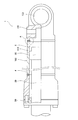
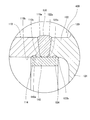
- FIG. 1 is a partial cross-sectional view of a hydraulic cylinder provided with a cylinder according to a first embodiment of the present invention.
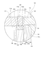
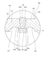
- FIG. 2 is an enlarged view of a portion A in FIG.
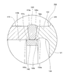
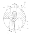
- FIG. 3 is a view showing the flow of force (line of force) transmitted from the cylinder bottom to the cylinder tube when the cylinder is subjected to a tensile load, corresponding to FIG.
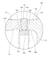
- FIG. 4 is an enlarged sectional view of a cylinder according to a second embodiment of the present invention.
- FIG. 5 is an enlarged sectional view of a cylinder according to a third embodiment of the present invention.
- FIG. 6 is an enlarged sectional view of a cylinder according to a fourth embodiment of the present invention.
- FIG. 7 is an enlarged sectional view of a cylinder according to a fifth embodiment of the present invention.
- FIG. 8 is an enlarged cross-sectional view of a cylinder according to a sixth embodiment of the present invention.
- the pressure resistant device is formed to be able to store fluid and receives the pressure of the fluid from the inside.
- the pressure resistant apparatus demonstrates the case where it is a cylinder 100, 200, 300, 400, 500, 600 used for the hydraulic cylinder 1 as a fluid pressure cylinder.
- a cylinder 100 and a hydraulic cylinder 1 according to a first embodiment of the present invention will be described with reference to FIGS. 1 to 3.
- the hydraulic cylinder 1 is provided along a hollow cylinder 100, a piston rod 20 inserted into the cylinder 100, and an end of the piston rod 20 along the inner circumferential surface of the cylinder 100.
- a piston 30 a piston 30.
- the piston 30 divides the inside of the cylinder 100 into a rod side chamber 4 and an opposite rod side chamber 5.
- the rod side chamber 4 and the non-rod side chamber 5 are filled with hydraulic oil as a working fluid.
- the piston rod 20 extends from the cylinder 100, and the hydraulic cylinder 1 is extended and contracted by the hydraulic oil supplied to and discharged from the cylinder 100. Specifically, when the hydraulic oil is supplied to the opposite rod side chamber 5 and the hydraulic oil is discharged from the rod side chamber 4, the hydraulic cylinder 1 operates to extend. Further, when the hydraulic oil is supplied to the rod side chamber 4 and the hydraulic oil is discharged from the opposite rod side chamber 5, the hydraulic cylinder 1 is contracted.
- the cylinder 100 includes a cylinder tube (cylindrical main body) 110 and a cylinder bottom (lid) 120 closing one opening of the cylinder tube 110.
- the other opening of the cylinder tube 110 is closed by a cylinder head 50 that slidably supports the piston rod 20.
- the cylinder bottom 120 is formed with a mounting portion 123 for mounting the hydraulic cylinder 1 to another device.
- the direction along the central axis of the cylinder tube 110 is referred to as “axial direction”
- the radial direction centering on the central axis of the cylinder tube 110 is referred to as “radial direction”
- the direction along the central axis of the cylinder tube 110 The direction is called "circumferential direction”.
- FIG. 2 is an enlarged view of a portion A in FIG.
- the cylinder bottom 120 has a bottom body 121 covering the opening of the cylinder tube 110 and an annular wall portion 122 extending in the axial direction from the bottom body 121.
- the tip end 122 a of the wall 122 is joined to the open end 110 a of the cylinder tube 110 by welding.
- the cylinder tube 110 and the cylinder bottom 120 are joined to each other through the joint 130 formed between the tip 122 a of the wall 122 and the open end 110 a of the cylinder tube 110.
- the welding may be performed by any method such as arc welding including plasma welding and TIG welding, gas welding, laser welding, electron beam welding, resistance welding, and friction welding.
- the cylinder 100 is provided with a buckling 140 as a positioning portion that determines the relative position between the cylinder tube 110 and the cylinder bottom 120.
- the back ring 140 is provided to face the inner circumferential surface 110 b of the cylinder tube 110 and the inner circumferential surface 122 b of the wall portion 122.
- the back ring 140 is formed separately from the cylinder tube 110 and the wall 122 when the cylinder tube 110 and the wall 122 are not joined.
- the buckling 140 is fitted to both the cylinder tube 110 and the wall 122.
- the cylinder tube 110 and the wall 122 are welded to each other so that the joint 130 reaches the inner circumference of the cylinder tube 110 and the wall 122. Therefore, the outer circumferential surface 140 a of the buckling 140 is joined to the joint 130. In the example illustrated in FIG. 2, only a part of the outer peripheral surface 140 a of the buckling 140 is bonded to the bonding portion 130, but the entire outer peripheral surface 140 a of the buckling 140 may be bonded to the bonding portion 130. .
- the joint portion 130 may protrude from the inner circumferential surface 110 b of the cylinder tube 110 and the inner circumferential surface 122 b of the wall 122. Even when the back ring 140 is provided on the inner circumference of the joint 130, the joint 130 may slightly protrude toward the back ring 140. In such a case, the roots 110 c and 122 c of the protrusions are formed in the joint 130. At the roots 110c and 122c, stress concentration is likely to occur when the cylinder 100 receives a tensile load in the axial direction.
- an annular groove 124 extending in the circumferential direction is formed in the inner peripheral surface 122b of the wall 122.
- the groove portion 124 is formed in an arc shape in cross section so that the maximum inner diameter D3 of the groove portion 124 is larger than the inner diameter D1 of the distal end portion 122a of the wall portion 122 and the inner diameter D2 of the open end 110a of the cylinder tube 110. Ru.
- the maximum inner diameter D3 of the groove 124 is simply referred to as "the inner diameter D3 of the groove 124".
- FIG. 3 is a diagram showing the flow of force (line of force) transmitted from the cylinder bottom 120 to the cylinder tube 110 when the cylinder 100 receives a tensile load in the axial direction, corresponding to FIG.
- lines of force are indicated by broken lines, and oblique lines indicating the cross sections of the cylinder tube 110, the cylinder bottom 120, and the joint portion 130 are omitted.
- the tensile load acts on the cylinder 100 by, for example, the pressure of hydraulic fluid in the cylinder 100 and the load connected to the hydraulic cylinder 1.
- the force acting on the cylinder bottom 120 is transmitted to the cylinder tube 110 through the joint 130.
- the path of force is narrowed by the groove 124. Since the inner diameter D3 of the groove 124 is larger than the inner diameter D1 of the tip 122a of the wall 122 and the inner diameter D2 of the open end 110a of the cylinder tube 110, the force mainly passes through the radially outer region of the joint 130 It is transmitted to the cylinder tube 110. Therefore, the force transmitted to the inner circumference of joint 130 can be reduced, and the stress at roots 110 c and 122 c of joint 130 can be reduced. Thereby, breakage of the roots 110 c and 122 c can be prevented, and the durability of the cylinder 100 can be improved.
- the groove 124 is preferably formed near the joint 130. This is because the force acting on the cylinder bottom 120 is transmitted to the cylinder tube 110 through the joint 130 while spreading radially inward after passing between the outer periphery of the wall 122 and the groove 124, and the groove 124 This is because the force transmitted to the inner circumferential surface of the joint 130 can be reduced as it is formed closer to the joint 130.
- the buckling 140 is provided to face an edge 124 a of the groove 124 on the joint 130 side. Specifically, the position of the edge of the outer circumferential surface 140 a of the buckling 140 coincides with the position of the edge 124 a of the groove 124. Therefore, the groove portion 124 is formed in the wall portion 122 without an interval in the axial direction from the buckling 140. Therefore, the dimension of the buckling 140 in the axial direction can be increased while bringing the groove 124 close to the joint 130, and the stress at the inner periphery of the joint 130 can be maintained while maintaining the positioning accuracy of the cylinder tube 110 and the cylinder bottom 120. It can be reduced. As a result, the cylinder 100 can be formed with high accuracy, and the durability can be improved.
- the entire outer circumferential surface 140 a of the buckling 140 is the inside of the inner circumferential surface 110 b of the cylinder tube 110 and the wall 122 It faces the circumferential surface 122 b. Therefore, the cylinder tube 110 and the wall portion 122 can be joined with their axes aligned with higher accuracy.
- first and second curved surface portions 124b and 124c having different radii of curvature are formed.
- the first curved surface portion 124b is formed in a curved surface shape from the bottom portion 124d of the groove portion 124 to the edge 124a
- the second curved surface portion 124c is formed in a curved surface shape on the opposite side to the edge 124a from the bottom portion 124d Be done.
- the radius of curvature of the first curved surface portion 124 b is smaller than the radius of curvature of the second curved surface portion 124 c. Therefore, the distance between the edge 124a of the groove 124 and the bottom 124d is smaller than in the case where the radius of curvature of the first curved surface section 124b is equal to or greater than the radius of curvature of the second curved surface section 124c. Therefore, the bottom 124d can be formed near the joint 130 without bringing the edge 124a close to the joint 130, and the stress at the inner periphery of the joint 130 while maintaining the positioning accuracy of the cylinder tube 110 and the cylinder bottom 120. Can be reduced more. As a result, the cylinder 100 can be formed with high accuracy, and the durability can be further improved.
- the buckling 140 is formed separately from the cylinder tube 110 and the cylinder bottom 120, and is provided to face the inner circumferential surface 110b of the cylinder tube 110 and the inner circumferential surface 122b of the wall portion 122. Therefore, it is possible to reduce the transfer of heat from the cylinder tube 110 and the cylinder bottom 120 to the buckling 140 at the time of welding. Therefore, the softening of the buckling 140 accompanying temperature rise can be prevented, and the protrusion of the joint 130 can be reduced. Thereby, stress concentration in the joint portion 130 can be alleviated, and the durability of the cylinder 100 can be further improved.
- the rigidity of the wall 122 is lower than that in the case where the groove 124 is not formed. Therefore, when the cylinder tube 110 is deformed by the tensile load or the pressure of the hydraulic fluid in the cylinder 100, the wall portion 122 can be deformed according to the deformation of the cylinder tube 110, which occurs at the roots 110c and 122c of the joint 130. Stress concentration can be relieved.
- the base of the wall portion 122 on the bottom main body 121 side serves as a fulcrum.
- the groove portion 124 is formed at a corner between the wall portion 122 and the bottom main body 121, and the rigidity of the root of the wall portion 122 is small. Therefore, the wall portion 122 can be more easily deformed according to the deformation of the cylinder tube 110. Therefore, the stress concentration generated at the roots 110 c and 122 c of the joint 130 can be further alleviated.
- the groove portion 124 is formed across the inner peripheral surface 122 b of the wall portion 122 and the end surface 121 a of the bottom main body 121. That is, the inner side surface of the groove portion 124 and the end surface 121 a of the bottom main body 121 are continuous without having a corner portion therebetween. Therefore, the radius of curvature of the groove 124 can be increased, and stress concentration in the groove 124 can be alleviated.
- the buckling 140 since the buckling 140 faces the edge 124a of the groove 124, the buckling 140 can be elongated while bringing the groove 124 close to the joint 130. Therefore, at the time of joining, it is possible to position the cylinder tube 110 and the cylinder bottom 120 with high accuracy, and after joining, it is possible to reduce the stress concentration at the inner periphery of the joined portion 130. Thereby, the cylinder 100 can be formed with high accuracy, and the durability of the cylinder 100 can be improved.
- the entire outer peripheral surface 140 a of the buckling 140 faces the inner peripheral surface 110 b of the cylinder tube 110 and the inner peripheral surface 122 b of the wall portion 122. Therefore, at the time of joining, the axes of the cylinder tube 110 and the wall portion 122 can be aligned with higher accuracy.
- the buckling 140 is formed separately from the cylinder tube 110 and the cylinder bottom 120, and is provided to face the inner circumferential surface 110b of the cylinder tube 110 and the inner circumferential surface 122b of the wall portion 122. Therefore, the softening of the buckling 140 at the time of welding can be prevented, and the protrusion of the joint 130 can be reduced. Thereby, stress concentration in the joint portion 130 can be alleviated, and the durability of the cylinder 100 can be further improved.
- the bottom portion 124 d can be formed near the joint portion 130 without bringing the edge 124 a close to the joint portion 130. Therefore, the stress at the inner periphery of the joint portion 130 can be further reduced, and the cylinder 100 can be formed with higher accuracy, and the durability can be further improved.
- a cylinder 200 according to a second embodiment of the present invention will be described with reference to FIG.
- the same components as those of the cylinder 100 according to the first embodiment are designated by the same reference numerals, and the description thereof is omitted.
- the hydraulic cylinder which can apply the cylinder 200 is substantially the same as the hydraulic cylinder 1 shown by FIG. 1, the illustration is abbreviate
- the buckling 140 overlaps the edge 124 a of the groove 124. Specifically, the buckling 140 extends beyond the edge 124 a of the groove 124 opposite to the joint 130.
- the groove portion 124 is formed in the wall portion 122 without leaving an axial space from the buckling 140 similarly to the cylinder 100. Therefore, the cylinder 200 can be formed with high accuracy, and the durability can be improved.
- first and second curved surface portions having different radii of curvature may be formed on the inner side surface of the groove portion 124 in the same manner as the groove portion 124 of the cylinder 100.
- a cylinder 300 according to a third embodiment of the present invention will be described with reference to FIG.
- the same components as those of the cylinder 100 according to the first embodiment are designated by the same reference numerals, and the description thereof is omitted.
- the hydraulic cylinder which can apply the cylinder 300 is substantially the same as the hydraulic cylinder 1 shown by FIG. 1, the illustration is abbreviate
- a groove 114 is formed on the inner circumferential surface 110b of the cylinder tube 110.
- the back ring 140 is provided to face the edge 114 a on the joint 130 side of the groove 114. Specifically, the position of the edge of the outer circumferential surface 140 a of the buckling 140 coincides with the position of the edge 114 a of the groove 114.
- the groove portion 114 is formed in the cylinder tube 110 without leaving an axial space from the buckling 140. Therefore, the cylinder 300 can be formed with high accuracy, and the durability can be improved.
- the buckling 140 may overlap the edge 114 a of the groove 114.
- first and second curved surface portions having different radii of curvature may be formed on the inner side surface of the groove portion 114.
- the groove 124 (see FIG. 2) or the groove 124 (see FIG. 4) may be formed on the inner circumferential surface 122b of the wall 122.
- a cylinder 400 according to a fourth embodiment of the present invention will be described with reference to FIG.
- the same components as those of the cylinders 100 and 300 according to the first and third embodiments are denoted by the same reference numerals, and the description thereof will be omitted.
- the hydraulic cylinder which can apply the cylinder 400 is substantially the same as the hydraulic cylinder 1 shown by FIG. 1, the illustration is abbreviate
- the grooves 114, 124 correspond to the inner circumferential surface 110b of the cylinder tube 110 and the cylinder bottom. They are formed on the inner circumferential surface 122 b of the wall portion 122.
- the back ring 140 is provided to cover the grooves 114 and 124.
- the groove portions 114 and 124 are formed in the wall portion 122 of the cylinder tube 110 and the cylinder bottom 120 without leaving an axial space from the buckling 140. Therefore, the cylinder 400 can be formed with high accuracy, and the durability can be improved.
- the buckling 140 is provided to cover the grooves 114 and 124. Therefore, the buckling 140 also faces in the region of the inner circumferential surface 110 b opposite to the joint portion 130 with respect to the groove portion 114. Similarly, the buckling 140 also faces in the region of the inner circumferential surface 122 b opposite to the joint portion 130 with respect to the groove portion 124. Therefore, the cylinder tube 110 and the cylinder bottom 120 can be positioned in a wider range of the outer peripheral surface 140a of the buckling 140, and the cylinder tube 110 and the wall portion 122 are aligned with higher accuracy with their axes. It can be joined in the state.
- first and second curved surface portions having different radii of curvature may be formed on the inner side surfaces of the groove portions 114 and 124 in the same manner as the groove portion 124 (see FIG. 2) of the cylinder 100.
- a cylinder 500 according to a fifth embodiment of the present invention will be described with reference to FIG.
- the same components as those of the cylinders 100 and 300 according to the first and third embodiments are denoted by the same reference numerals, and the description thereof will be omitted.
- the hydraulic cylinder which can apply the cylinder 500 is substantially the same as the hydraulic cylinder 1 shown by FIG. 1, the illustration is abbreviate
- the cylinder tube 510 has a tube main body 511 accommodating the piston 30 (see FIG. 1), and an annular portion 512 axially and annularly extending from one end of the tube main body 511.
- the inner diameter of the tube main body 511 corresponds to the so-called cylinder diameter, and the inner diameter of the annular portion 512 is larger than the inner diameter of the tube main body 511.
- the tip of the annular portion 512 is the open end 510 a of the cylinder tube 510, and the tip of the annular portion 512 forms an opening of the cylinder tube 510. That is, the annular portion 512 is joined to the wall 522 of the cylinder bottom 520 by welding. In other words, the cylinder tube 510 and the cylinder bottom 520 are joined to each other through the joint 130 formed between the tip end 522 a of the wall 522 and the open end 510 a of the cylinder tube 510.
- the welding may be performed by any method such as arc welding including plasma welding and TIG welding, gas welding, laser welding, electron beam welding, resistance welding, and friction welding.
- the back ring 140 is provided to face the inner circumferential surface 510 b of the annular portion 512 of the cylinder tube 510 and the inner circumferential surface 522 b of the wall portion 522. Therefore, it is possible to join the annular portion 512 of the cylinder tube 510 and the wall portion 522 of the cylinder bottom 520 in a state where their axes are aligned.
- An annular groove 514 extending in the circumferential direction is formed on the inner circumferential surface 510 b of the annular portion 512, and an annular groove 524 extending in the circumferential direction is formed on the inner circumferential surface 522 b of the wall 522.
- the position of the edge of the outer circumferential surface 140 a of the buckling 140 coincides with the position of the edge 514 a, 524 a on the joint portion 130 side in the groove portions 514, 524. Therefore, the cylinder 500 can be formed with high accuracy, and the durability can be improved.
- the buckling 140 may be provided to overlap the edges 514 a and 524 a of the grooves 514 and 524.
- the buckling 14 may be provided so as to cover the grooves 514 and 524.
- first and second curved surface portions having different radii of curvature may be formed on the inner side surfaces of the groove portions 514 and 524 similarly to the groove portion 124 (see FIG. 2) of the cylinder 100.
- the cylinder 500 is not limited to the configuration in which the groove portion 514 and the groove portion 524 are formed in both the inner peripheral surface 510 b of the annular portion 512 and the inner peripheral surface 522 b of the wall portion 522.
- the groove portion 514 may be formed only on the inner circumferential surface 510 b of the annular portion 512, and the groove portion 524 may not be formed on the inner circumferential surface 522 b of the wall portion 522.
- the groove portion 524 may be formed only on the inner peripheral surface 522 b of the wall portion 522, and the groove portion 514 may not be formed on the inner peripheral surface 510 b of the annular portion 512.
- a cylinder 600 according to a sixth embodiment of the present invention will be described with reference to FIG.
- the same components as those of the cylinder 100 according to the first embodiment are designated by the same reference numerals, and the description thereof is omitted.
- the hydraulic cylinder which can apply the cylinder 600 is substantially the same as the hydraulic cylinder 1 shown by FIG. 1, the illustration is abbreviate
- the cylinder 600 includes a back portion 640 as a positioning portion integrally formed with the wall portion 622 of the cylinder bottom 620, instead of the buckling 140 (see FIG. 2) of the cylinder 100 according to the first embodiment.
- the back portion 640 is formed separately from the cylinder tube 110 in a state where the cylinder tube 110 and the wall portion 622 are not joined. When the cylinder tube 110 and the wall portion 622 are joined, the back portion 640 is fitted to the cylinder tube 110. Thus, relative movement between the cylinder tube 110 and the cylinder bottom 620 can be prevented at the time of joining, and the cylinder tube 110 and the wall portion 622 can be joined in a state where their axial centers are aligned.
- the back portion 640 is integrally formed with the wall portion 622, when the back portion 640 is fitted to the cylinder tube 110, the back portion 640 can be prevented from moving relative to the wall portion 622. Therefore, cylinder tube 110 and wall portion 622 can be easily joined, and cylinder 600 can be easily manufactured.
- the joint portion 130 reaches the inner periphery of the cylinder tube 110. Therefore, the outer peripheral surface 640 a of the back portion 640 is bonded to the bonding portion 130. In the example shown in FIG. 8, only a part of the outer peripheral surface 640 a of the back portion 640 is bonded to the bonding portion 130, but the entire outer peripheral surface 640 a of the back portion 640 may be bonded to the bonding portion 130. .
- An annular groove 114 extending in the circumferential direction is formed on the inner circumferential surface 110 b of the cylinder tube 110.
- the position of the edge of the outer circumferential surface 640 a of the back portion 640 matches the position of the edge 114 a on the joint portion 130 side of the groove portion 114. Therefore, the groove portion 114 is formed in the cylinder tube 110 without leaving an interval in the axial direction from the back portion 640. Therefore, the groove portion 114 can be formed near the joint portion 130 without shortening the dimension of the back portion 640 in the axial direction. This makes it possible to form the cylinder 600 with high accuracy and to improve the durability.
- An annular groove 624 is formed on the inner circumferential surface 622 b of the wall 622.
- the inner diameter D3 of the groove 624 is larger than the inner diameter D2 of the open end 110a of the cylinder tube 110. Therefore, the force transmitted to the inner periphery of the joint 130 can be reduced also by the groove 624, and the stress at the root 110c of the joint 130 can be reduced. Thereby, damage to the root 110 c can be prevented, and the durability of the cylinder 600 can be improved.
- the back portion 640 may be provided to overlap with the edge 114 a of the groove portion 114.
- the back portion 640 may be provided to cover the groove portion 114.
- first and second curved surface portions having different radii of curvature may be formed on the inner side surface of the groove 114.
- the back portion 640 may be formed integrally with the cylinder tube 110 instead of the wall portion 622.
- the opening of the cylinder tube 110 is closed by the cylinder bottom 120 shown in FIG. 2 instead of the cylinder bottom 620, and the position of the edge 124a of the groove 124 is the back portion 640 integrally formed with the cylinder tube 110. It coincides with the position of the edge of the outer circumferential surface 640a.
- the cylinders 100, 200, 300, 400, 500, 600 have cylinder tubes 110, 510 and annular wall portions 122, 522, 622, and the wall portions 122, 522, 622 and the cylinder tubes 110, 510 are mutually different.
- the cylinder bottoms 120, 520, 620 which are joined and close the opening of the cylinder tubes 110, 510, and the inner peripheral surfaces 110b, 122b, 510b, 522b, 622b of the cylinder tubes 110, 510 and the walls 122, 522, 622 are opposed.
- the back ring 140 or back portion 640 which determines the relative position between the cylinder tube 110, 510 and the cylinder bottom 120, 520, 620.
- the buckling 140 or the back portion 640 it is possible to lengthen the buckling 140 or the back portion 640 while bringing the grooves 114, 124, 514, 524 close to the joint portion 130 between the wall portions 122, 522, 622 and the cylinder tubes 110, 510. Therefore, at the time of joining, the cylinder tubes 110 and 510 and the cylinder bottoms 120, 520 and 620 can be positioned with high accuracy, and after the joining, stress at the inner periphery of the joined portion 130 can be reduced. As a result, the molding accuracy and durability of the cylinders 100, 200, 300, 400, 500, 600 can be improved.
- the buckling 140 is formed separately from the cylinder tubes 110, 510 and the cylinder bottoms 120, 520, and the buckling of the cylinder tubes 110, 510 and the wall portions 122, 522. It is provided facing both inner skins 110b, 122b, 510b, 522b.
- the back ring 140 or the back portion 640 is provided such that the position of the edge thereof matches the position of the edge of the groove portion 114, 124, 514, 524.
- the entire outer peripheral surface 140a, 640a of the buckling 140 or the back portion 640 faces the cylinder tube 110, 510 and the inner peripheral surface 110b, 510b, 122b, 522b of the wall portion 122, 522. Therefore, the cylinder tubes 110 and 510 and the wall portions 122 and 522 can be joined in a state where their axes are aligned with higher accuracy.
- the cylinder 400 and the buckling 140 are provided so as to cover the groove portions 114 and 124.
- the buckling 140 also faces in the region of the inner circumferential surfaces 110 b and 122 b opposite to the joint portion 130 with respect to the groove portions 114 and 124. Therefore, the positioning accuracy between the cylinder tube 110 and the cylinder bottom 120 can be further improved.
- the inner side surface of the groove portion 124 is a first curved surface portion 124b formed in a curved shape from the bottom portion 124d of the groove toward the joint portion 130, and the opposite side to the joint portion 130 from the bottom portion 124d of the groove.
- the second curved surface portion 124c is formed in a curved surface shape, and the radius of curvature of the first curved surface portion 124b is smaller than the radius of curvature of the second curved surface portion 124c.
- the bottom 124 d of the groove 124 can be brought close to the joint 130 without the edge 124 a of the groove 124 being brought close to the joint 130. Therefore, the stress at the inner periphery of the joint portion 130 can be further reduced, and the durability of the cylinder 100 can be further improved.
- the present embodiment relates to a hydraulic cylinder 1 that is extended and contracted by supplying and discharging hydraulic oil to the cylinder.
- the cylinders are the cylinders 100, 200, 300, 400, 500, 600.
- the cylinders are the aforementioned cylinders 100, 200, 300, 400, 500, 600, the cylinders have high durability. Therefore, the durability of the hydraulic cylinder 1 can be improved.
- the groove portions 114, 124, 514, 524, 624 are formed on the entire circumference in the circumferential direction, but the groove portions 114, 124, 514, 524, 624 are formed in a part in the circumferential direction It may be done.
- the cross section of the groove portions 114, 124, 514, 524, 624 may have a shape other than an arc shape, for example, a shape such as a triangle or a square.
- the cross sections of the grooves 114, 124, 514, 524, 624 are preferably arcuate, in which case stress concentration in the grooves 114, 124, 514, 524, 624 can be alleviated.
- the cylinder used for the hydraulic cylinder 1 was demonstrated as a pressure
- the pressure resistant apparatus is not limited to this, and may be a pressure vessel such as a cylinder for storing liquid or gas.
Landscapes
- Engineering & Computer Science (AREA)
- General Engineering & Computer Science (AREA)
- Mechanical Engineering (AREA)
- Physics & Mathematics (AREA)
- Optics & Photonics (AREA)
- Fluid Mechanics (AREA)
- Plasma & Fusion (AREA)
- Actuator (AREA)
- Pistons, Piston Rings, And Cylinders (AREA)
- Pressure Vessels And Lids Thereof (AREA)
- Butt Welding And Welding Of Specific Article (AREA)
Priority Applications (3)
| Application Number | Priority Date | Filing Date | Title |
|---|---|---|---|
| US16/642,746 US11174881B2 (en) | 2017-10-05 | 2018-09-27 | Pressure resistant device and fluid pressure cylinder |
| DE112018004418.1T DE112018004418B4 (de) | 2017-10-05 | 2018-09-27 | Druck-feste Vorrichtung und Fluid-Druck-Zylinder |
| CN201880058617.5A CN111051709B (zh) | 2017-10-05 | 2018-09-27 | 耐压设备及流体压缸 |
Applications Claiming Priority (2)
| Application Number | Priority Date | Filing Date | Title |
|---|---|---|---|
| JP2017194856A JP6530800B2 (ja) | 2017-10-05 | 2017-10-05 | 耐圧機器及び流体圧シリンダ |
| JP2017-194856 | 2017-10-05 |
Publications (1)
| Publication Number | Publication Date |
|---|---|
| WO2019069797A1 true WO2019069797A1 (ja) | 2019-04-11 |
Family
ID=65995040
Family Applications (1)
| Application Number | Title | Priority Date | Filing Date |
|---|---|---|---|
| PCT/JP2018/036085 Ceased WO2019069797A1 (ja) | 2017-10-05 | 2018-09-27 | 耐圧機器及び流体圧シリンダ |
Country Status (5)
| Country | Link |
|---|---|
| US (1) | US11174881B2 (enExample) |
| JP (1) | JP6530800B2 (enExample) |
| CN (1) | CN111051709B (enExample) |
| DE (1) | DE112018004418B4 (enExample) |
| WO (1) | WO2019069797A1 (enExample) |
Families Citing this family (3)
| Publication number | Priority date | Publication date | Assignee | Title |
|---|---|---|---|---|
| JP2021143748A (ja) * | 2020-03-13 | 2021-09-24 | Kyb株式会社 | 耐圧機器及び流体圧シリンダ |
| JP7530217B2 (ja) * | 2020-06-10 | 2024-08-07 | カヤバ株式会社 | 耐圧機器及び流体圧シリンダ |
| DE102021001107A1 (de) * | 2021-03-02 | 2022-09-08 | Bümach Engineering International B.V. | Arbeitszylinder und Verfahren zu dessen Herstellung |
Citations (3)
| Publication number | Priority date | Publication date | Assignee | Title |
|---|---|---|---|---|
| JPS591493U (ja) * | 1982-06-29 | 1984-01-07 | 日立建機株式会社 | シリンダの溶接構造 |
| WO2014184291A2 (de) * | 2013-05-16 | 2014-11-20 | Schwing Gmbh | BAUTEIL MIT MINDESTENS ZWEI MITEINANDER VERSCHWEIßTEN TEILEN |
| WO2017183561A1 (ja) * | 2016-04-18 | 2017-10-26 | Kyb株式会社 | 耐圧機器及び流体圧シリンダ |
Family Cites Families (15)
| Publication number | Priority date | Publication date | Assignee | Title |
|---|---|---|---|---|
| US3559540A (en) * | 1968-08-06 | 1971-02-02 | Arnold C Sheldon | Hydraulic actuator |
| US4324171A (en) * | 1978-06-16 | 1982-04-13 | Clark Equipment Company | Fluid device and method for making |
| JPS6075703U (ja) * | 1983-10-31 | 1985-05-27 | カヤバ工業株式会社 | 油圧シリンダ |
| US5651303A (en) * | 1994-11-14 | 1997-07-29 | Polygon Company | Fluid cylinder end cap assembly |
| JP4083596B2 (ja) * | 2003-02-26 | 2008-04-30 | ユニシア ジェーケーシー ステアリングシステム株式会社 | パワーステアリング装置 |
| NL2001389C2 (nl) * | 2008-03-19 | 2009-09-22 | Actuant Corp | Hydraulische cilinder en werkwijze voor het vervaardigen daarvan. |
| CN201730889U (zh) * | 2009-10-28 | 2011-02-02 | 海克力斯(上海)液压机械有限公司 | 高压液压油缸缸头焊接结构装置 |
| DE202012009001U1 (de) * | 2012-09-19 | 2014-01-15 | Bümach Engineering International B.V. | Arbeitszylinder |
| JP5981877B2 (ja) * | 2013-04-26 | 2016-08-31 | 川崎重工業株式会社 | 液圧回転機が備えるピストン及び液圧回転機 |
| JP6098880B2 (ja) * | 2013-05-07 | 2017-03-22 | Smc株式会社 | 流体圧シリンダ |
| CN104632759A (zh) * | 2015-01-23 | 2015-05-20 | 山东隆源液压科技有限公司 | 一种属具快换油缸 |
| JP6774210B2 (ja) * | 2016-04-18 | 2020-10-21 | Kyb株式会社 | 耐圧機器及び流体圧シリンダ |
| JP2017194087A (ja) * | 2016-04-18 | 2017-10-26 | Kyb株式会社 | 耐圧機器及び流体圧シリンダ |
| JP2017194856A (ja) | 2016-04-21 | 2017-10-26 | 株式会社リコー | 情報処理装置、情報処理方法、および情報処理プログラム |
| US10697479B1 (en) * | 2017-06-09 | 2020-06-30 | JARP Industries, Inc. | Pressure vessel and method of welding a pressure vessel sidewall and end cap together |
-
2017
- 2017-10-05 JP JP2017194856A patent/JP6530800B2/ja active Active
-
2018
- 2018-09-27 WO PCT/JP2018/036085 patent/WO2019069797A1/ja not_active Ceased
- 2018-09-27 DE DE112018004418.1T patent/DE112018004418B4/de active Active
- 2018-09-27 US US16/642,746 patent/US11174881B2/en active Active
- 2018-09-27 CN CN201880058617.5A patent/CN111051709B/zh active Active
Patent Citations (3)
| Publication number | Priority date | Publication date | Assignee | Title |
|---|---|---|---|---|
| JPS591493U (ja) * | 1982-06-29 | 1984-01-07 | 日立建機株式会社 | シリンダの溶接構造 |
| WO2014184291A2 (de) * | 2013-05-16 | 2014-11-20 | Schwing Gmbh | BAUTEIL MIT MINDESTENS ZWEI MITEINANDER VERSCHWEIßTEN TEILEN |
| WO2017183561A1 (ja) * | 2016-04-18 | 2017-10-26 | Kyb株式会社 | 耐圧機器及び流体圧シリンダ |
Also Published As
| Publication number | Publication date |
|---|---|
| DE112018004418T5 (de) | 2020-05-20 |
| US20210079937A1 (en) | 2021-03-18 |
| JP2019063853A (ja) | 2019-04-25 |
| CN111051709B (zh) | 2021-12-21 |
| JP6530800B2 (ja) | 2019-06-12 |
| CN111051709A (zh) | 2020-04-21 |
| DE112018004418B4 (de) | 2025-11-06 |
| US11174881B2 (en) | 2021-11-16 |
Similar Documents
| Publication | Publication Date | Title |
|---|---|---|
| WO2019069797A1 (ja) | 耐圧機器及び流体圧シリンダ | |
| JP6324902B2 (ja) | 向上した燃焼ボウル縁部領域を有する一体型ピストンおよび製造方法 | |
| JP2017194087A (ja) | 耐圧機器及び流体圧シリンダ | |
| WO2017061276A1 (ja) | 接合体、流体圧シリンダ、及び接合体の製造方法 | |
| JP4253644B2 (ja) | 内燃機関用ピストンの製造方法 | |
| US20220397129A1 (en) | Working cylinder | |
| TW201610333A (zh) | 隔膜伸縮管 | |
| JP5631314B2 (ja) | 内燃機関用のピストン | |
| JP4518275B2 (ja) | 軽量バルブ | |
| JP5035771B2 (ja) | 真空用バルブ | |
| JP6774210B2 (ja) | 耐圧機器及び流体圧シリンダ | |
| US11441454B2 (en) | Valve for internal combustion engines having a guide vane for coolant | |
| CN104507629B (zh) | 流体操作的线性驱动装置的驱动单元及用于其制造的方法 | |
| JP7365403B2 (ja) | ベローズ型アキュムレータ | |
| JPWO2019102983A1 (ja) | メタルダイアフラムダンパ及びその製造方法 | |
| US20190128291A1 (en) | Pressure resistant apparatus and fluid pressure cylinder | |
| JP7530217B2 (ja) | 耐圧機器及び流体圧シリンダ | |
| JP6803271B2 (ja) | アキュムレータ | |
| FR3115829B1 (fr) | Fixation d’un cône d’éjection dans une tuyère de turbomachine | |
| JP2021085546A (ja) | パワーエレメント及びこれを用いた膨張弁 | |
| CN110418900B (zh) | 储压器 | |
| WO2021182184A1 (ja) | 耐圧機器及び流体圧シリンダ | |
| JP2022068870A (ja) | フランジ接続部 | |
| JP2023129901A (ja) | 溶接式管継手 | |
| KR102709269B1 (ko) | 전기 기계 및 그 제조 방법 |
Legal Events
| Date | Code | Title | Description |
|---|---|---|---|
| 121 | Ep: the epo has been informed by wipo that ep was designated in this application |
Ref document number: 18864844 Country of ref document: EP Kind code of ref document: A1 |
|
| WWE | Wipo information: entry into national phase |
Ref document number: 112018004418 Country of ref document: DE |
|
| WWP | Wipo information: published in national office |
Ref document number: 112018004418 Country of ref document: DE |
|
| 122 | Ep: pct application non-entry in european phase |
Ref document number: 18864844 Country of ref document: EP Kind code of ref document: A1 |
|
| WWG | Wipo information: grant in national office |
Ref document number: 112018004418 Country of ref document: DE |