WO2019069789A1 - 電極触媒層、膜電極接合体、および、固体高分子形燃料電池 - Google Patents
電極触媒層、膜電極接合体、および、固体高分子形燃料電池 Download PDFInfo
- Publication number
- WO2019069789A1 WO2019069789A1 PCT/JP2018/035936 JP2018035936W WO2019069789A1 WO 2019069789 A1 WO2019069789 A1 WO 2019069789A1 JP 2018035936 W JP2018035936 W JP 2018035936W WO 2019069789 A1 WO2019069789 A1 WO 2019069789A1
- Authority
- WO
- WIPO (PCT)
- Prior art keywords
- polymer electrolyte
- catalyst layer
- electrode catalyst
- fiber
- electrode
- Prior art date
Links
Images


Classifications
-
- H—ELECTRICITY
- H01—ELECTRIC ELEMENTS
- H01M—PROCESSES OR MEANS, e.g. BATTERIES, FOR THE DIRECT CONVERSION OF CHEMICAL ENERGY INTO ELECTRICAL ENERGY
- H01M4/00—Electrodes
- H01M4/86—Inert electrodes with catalytic activity, e.g. for fuel cells
- H01M4/8663—Selection of inactive substances as ingredients for catalytic active masses, e.g. binders, fillers
- H01M4/8673—Electrically conductive fillers
-
- H—ELECTRICITY
- H01—ELECTRIC ELEMENTS
- H01M—PROCESSES OR MEANS, e.g. BATTERIES, FOR THE DIRECT CONVERSION OF CHEMICAL ENERGY INTO ELECTRICAL ENERGY
- H01M4/00—Electrodes
- H01M4/86—Inert electrodes with catalytic activity, e.g. for fuel cells
- H01M4/90—Selection of catalytic material
- H01M4/92—Metals of platinum group
- H01M4/925—Metals of platinum group supported on carriers, e.g. powder carriers
- H01M4/926—Metals of platinum group supported on carriers, e.g. powder carriers on carbon or graphite
-
- H—ELECTRICITY
- H01—ELECTRIC ELEMENTS
- H01M—PROCESSES OR MEANS, e.g. BATTERIES, FOR THE DIRECT CONVERSION OF CHEMICAL ENERGY INTO ELECTRICAL ENERGY
- H01M8/00—Fuel cells; Manufacture thereof
- H01M8/10—Fuel cells with solid electrolytes
- H01M2008/1095—Fuel cells with polymeric electrolytes
-
- Y—GENERAL TAGGING OF NEW TECHNOLOGICAL DEVELOPMENTS; GENERAL TAGGING OF CROSS-SECTIONAL TECHNOLOGIES SPANNING OVER SEVERAL SECTIONS OF THE IPC; TECHNICAL SUBJECTS COVERED BY FORMER USPC CROSS-REFERENCE ART COLLECTIONS [XRACs] AND DIGESTS
- Y02—TECHNOLOGIES OR APPLICATIONS FOR MITIGATION OR ADAPTATION AGAINST CLIMATE CHANGE
- Y02E—REDUCTION OF GREENHOUSE GAS [GHG] EMISSIONS, RELATED TO ENERGY GENERATION, TRANSMISSION OR DISTRIBUTION
- Y02E60/00—Enabling technologies; Technologies with a potential or indirect contribution to GHG emissions mitigation
- Y02E60/30—Hydrogen technology
- Y02E60/50—Fuel cells
Definitions
- the present invention relates to an electrode catalyst layer provided in a fuel cell, a membrane electrode assembly provided with the electrode catalyst layer, and a polymer electrolyte fuel cell.
- Fuel cells have attracted attention as batteries contributing to solving environmental problems and energy problems. Fuel cells generate electrical power using a chemical reaction between a fuel such as hydrogen and an oxidant such as oxygen. Among fuel cells, a polymer electrolyte fuel cell can be operated at low temperature and can be miniaturized, and therefore, it is expected to be used as a portable power source, a household power source, a vehicle power source, and the like.
- the polymer electrolyte fuel cell comprises an electrode catalyst layer constituting a fuel electrode as an anode, an electrode catalyst layer constituting an air electrode as a cathode, and a polymer electrolyte membrane sandwiched between these two electrode catalyst layers.
- the membrane electrode assembly is provided.
- a fuel gas containing hydrogen is supplied to the electrode catalyst layer constituting the fuel electrode, and an oxidant gas containing oxygen is supplied to the electrode catalyst layer constituting the air electrode.
- an oxidant gas containing oxygen is supplied to the electrode catalyst layer constituting the air electrode.
- the fuel electrode H 2 ⁇ 2H + + 2e - Cathode: 1 / 2O 2 + 2H + + 2e - ⁇ H 2 O That is, protons and electrons are generated from the fuel gas supplied to the fuel electrode by the action of the catalyst contained in the electrode catalyst layer.
- the protons are conducted by the polymer electrolyte contained in the electrode catalyst layer and the polymer electrolyte membrane, and move to the air electrode through the polymer electrolyte membrane. Electrons are extracted from the electrode catalyst layer to the external circuit, and travel to the air electrode through the external circuit.
- the oxidant gas reacts with protons and electrons transferred from the fuel electrode to produce water. In this way, current flows as electrons pass through external circuits.
- a crack may occur in the electrode catalyst layer due to shrinkage due to drying or the like when forming the electrode catalyst layer. If a crack is present in the electrode catalyst layer, the polymer electrolyte membrane is exposed from the portion of the crack in the membrane electrode assembly, and the exposure of such a polymer electrolyte membrane causes a decrease in the durability of the membrane electrode assembly or a solid polymer. Of the power generation performance of the fuel cell.
- An object of the present invention is to provide an electrode catalyst layer, a membrane electrode assembly, and a polymer electrolyte fuel cell capable of suppressing the occurrence of a crack.
- the electrode catalyst layer which solves the said subject contains the carbon particle which carry
- a structure in which the organic electrolyte fibers are intertwined is formed in the electrode catalyst layer, and this structure functions as a support for the aggregates in the electrode catalyst layer, so that the occurrence of cracks in the electrode catalyst layer can be suppressed.
- the average fiber diameter of the said organic electrolyte fiber is 1 micrometer or less. According to the above configuration, sufficient pores are formed in the electrode catalyst layer, so that the output of the polymer electrolyte fuel cell provided with this electrode catalyst layer can be improved.
- the average fiber length of the said organic electrolyte fiber is 1 micrometer or more and 200 micrometers or less. According to the above configuration, the aggregation of the organic electrolyte fiber in the electrode catalyst layer can be suppressed, so that the pores are easily formed. In addition, since a structure in which organic electrolyte fibers are intertwined is suitably formed in the electrode catalyst layer, the strength of the electrode catalyst layer is enhanced, and as a result, the effect of suppressing the occurrence of cracks is enhanced.
- the electrode catalyst layer may further include carbon fibers. According to the above configuration, in the electrode catalyst layer, the proton conductivity can be improved by the organic electrolyte fiber and the electron conductivity can be improved by the carbon fiber. Therefore, the output of the polymer electrolyte fuel cell provided with this electrode catalyst layer Improvement is possible.
- the ratio of the total mass of the organic electrolyte fiber to the total mass of the carbon particles contained in the electrode catalyst layer is preferably 0.1 or more and 3.0 or less. According to the above configuration, conduction of protons in the electrode catalyst layer is promoted, so that the output of the polymer electrolyte fuel cell provided with the electrode catalyst layer can be improved.
- the organic electrolyte fiber may be composed of a polymer electrolyte. According to the above configuration, proton conductivity in the electrode catalyst layer can be enhanced.
- the organic electrolyte fiber is preferably made of a polymer electrolyte, and the ratio of the total mass of the aggregate to the total mass of the carbon particles contained in the electrode catalyst layer is preferably 1.0 or less.
- the electrode catalyst layer contains a fiber made of a polymer electrolyte, good proton conductivity can be obtained even if the ratio of aggregates is high. As a result, it is possible to improve the output of the polymer electrolyte fuel cell provided with the electrode catalyst layer.
- a membrane / electrode assembly for solving the above problems comprises a polymer electrolyte membrane and a pair of electrode catalyst layers sandwiching the polymer electrolyte membrane, and at least one of the pair of electrode catalyst layers is the electrode catalyst layer. is there.
- a membrane electrode assembly including the electrode catalyst layer in which the occurrence of cracks is suppressed is realized.
- a polymer electrolyte fuel cell which solves the above-mentioned subject is provided with the above-mentioned membrane electrode assembly and a pair of separators which sandwich the above-mentioned membrane electrode assembly.
- the occurrence of a crack in the electrode catalyst layer can be suppressed.
- FIG. 1 shows a perspective view of a polymer electrolyte fuel cell according to an embodiment.
- FIGS. 1 to 4 An embodiment of an electrode catalyst layer, a membrane electrode assembly, and a polymer electrolyte fuel cell will be described with reference to FIGS. 1 to 4.
- Electrode catalyst layer and membrane electrode assembly The structure of a membrane electrode assembly including an electrode catalyst layer and an electrode catalyst layer will be described with reference to FIGS. 1 to 3.
- the membrane electrode assembly 10 includes a polymer electrolyte membrane 11, and two electrode catalyst layers of a fuel electrode catalyst layer 12A and an air electrode catalyst layer 12C.
- the fuel electrode catalyst layer 12A is an electrode catalyst layer used for a fuel electrode which is an anode of a polymer electrolyte fuel cell
- the air electrode catalyst layer 12C is used for an air electrode which is a cathode of a polymer electrolyte fuel cell It is an electrode catalyst layer.
- the polymer electrolyte membrane 11 is sandwiched between the anode catalyst layer 12A and the cathode catalyst layer 12C.
- the anode catalyst layer 12A is in contact with one of the two surfaces of the polymer electrolyte membrane 11, and the cathode catalyst layer 12C is in contact with the other of the two surfaces of the polymer electrolyte membrane 11.
- the outer shape of the fuel electrode catalyst layer 12A and the outer shape of the air electrode catalyst layer 12C have substantially the same shape, and the outer shapes of these catalyst layers 12A and 12C.
- the outer shape of the polymer electrolyte membrane 11 is larger than that.
- the outer shape of the polymer electrolyte membrane 11 and the shapes of the outer shapes of the catalyst layers 12A and 12C are not particularly limited, and may be, for example, rectangular.
- the polymer electrolyte membrane 11 contains a polymer electrolyte.
- the polymer electrolyte used for the polymer electrolyte membrane 11 may be a polymer electrolyte having proton conductivity, and for example, a fluorine-based polymer electrolyte or a hydrocarbon-based polymer electrolyte is used.
- a fluorine-based polymer electrolyte include Nafion (registered trademark: manufactured by DuPont).
- As a hydrocarbon type polymer electrolyte the compound etc. which introduce
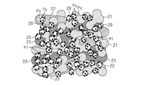
- FIG. 2 schematically shows a first configuration of the electrode catalyst layer of the present embodiment.
- each of the anode catalyst layer 12A and the cathode catalyst layer 12C is a catalyst substance-supporting carbon body 20 which is a carbon particle Pc carrying a catalyst substance Ps and an aggregate 21 of a polymer electrolyte.
- a polymer electrolyte fiber 22 which is a fibrous polymer electrolyte.
- the polymer electrolyte fiber 22 is an example of an organic electrolyte fiber.
- the aggregates 21 and the polymer electrolyte fibers 22 are located around the dispersed catalyst substance-supporting carbon body 20, and holes H1 are formed between them.
- the catalyst substance Ps for example, platinum group elements of platinum, palladium, ruthenium, iridium, rhodium, osmium, metals such as iron, lead, copper, chromium, cobalt, nickel, manganese, vanadium, molybdenum, gallium, aluminum, etc. Alternatively, these alloys, oxides, double oxides and the like are used. In particular, platinum or a platinum alloy is preferably used as the catalyst substance Ps.
- the average particle diameter of the plurality of catalyst substances Ps contained in the electrode catalyst layer is preferably 0.5 nm or more and 20 nm or less, and more preferably 1 nm or more and 5 nm or less. If the average particle size of the catalyst substance Ps is equal to or more than the above lower limit, the stability as a catalyst is enhanced. If the average particle size of the catalyst substance Ps is equal to or less than the above upper limit, the activity as a catalyst is enhanced.
- the carbon particles Pc may be in the form of fine particles having conductivity and being a support that is not attacked by the catalyst.
- the carbon particles Pc for example, a powdery carbon material made of carbon black, graphite, graphite, activated carbon, carbon nanotubes, fullerene or the like is used.
- the average particle diameter of the plurality of carbon particles Pc contained in the electrode catalyst layer is preferably 10 nm or more and 1000 nm or less, and more preferably 10 nm or more and 100 nm or less. If the average particle diameter of the carbon particles Pc is equal to or more than the above lower limit, a path of electron conduction is easily formed in the electrode catalyst layer. If the average particle size of the carbon particles Pc is equal to or less than the above upper limit value, the electrode catalyst layer can be formed thin to the extent that the resistance does not become excessive, so that a decrease in the output of the fuel cell can be suppressed.
- the carbon material supporting the catalyst substance Ps is in the form of particles, the area capable of supporting the catalyst substance Ps in the carbon material can be increased, and the catalyst substance Ps can be supported on the carbon material with high density. Therefore, the catalytic activity can be improved.
- the polymer electrolyte aggregate 21 is a mass in which an ionomer polymer electrolyte is aggregated by aggregation. Cohesion includes coulomb and van der Waals forces acting between ionomers.
- the polymer electrolyte fiber 22 is a polymer electrolyte having a shape elongated and elongated by crosslinking or the like.
- the polymer electrolyte constituting the aggregate 21 and the polymer electrolyte fiber 22 may be a polymer electrolyte having proton conductivity, and for example, a fluorine-based polymer electrolyte or a hydrocarbon-based polymer electrolyte is used.
- a fluorine-based polymer electrolyte include Nafion (registered trademark: manufactured by DuPont).
- a hydrocarbon type polymer electrolyte the compound etc. which introduce
- the polymer electrolyte constituting the aggregate 21 and the polymer electrolyte constituting the polymer electrolyte fiber 22 may be identical to or different from each other. Moreover, the polymer electrolyte which comprises each of the aggregate 21 and the polymer electrolyte fiber 22, and the polymer electrolyte which comprises the polymer electrolyte membrane 11 may be the same, and may mutually differ. In order to enhance the adhesion between the catalyst layers 12A and 12C and the polymer electrolyte membrane 11, the polymer electrolyte contained in the catalyst layers 12A and 12C and the polymer electrolyte contained in the polymer electrolyte membrane 11 are the same material. Is preferred.
- the polymer electrolyte fibers 22 are contained in the catalyst layers 12A and 12C, the polymer electrolyte fibers 22 are intertwined to function as a support in the electrode catalyst layer, so that cracking or the like of the electrode catalyst layer can be suppressed. Therefore, generation of cracks in the electrode catalyst layer can be suppressed as compared with the case where the electrode catalyst layer is constituted of the catalyst substance-supporting carbon body 20 and the aggregate 21 of the polymer electrolyte as in the related art.
- the aggregate 21 of the polymer electrolyte intrudes into the gaps between the plurality of polymer electrolyte fibers 22 to form an electrode catalyst layer only from the catalyst substance-supporting carbon body 20 and the polymer electrolyte fiber 22.
- the probability of contact between the catalyst substance Ps and the polyelectrolyte is increased as compared to the case where the catalyst is used. That is, it is possible to increase the number of locations where the three-phase interface is formed, and as a result, the electrode reaction is promoted to enhance the output of the polymer electrolyte fuel cell.
- the average fiber diameter of the plurality of polymer electrolyte fibers 22 contained in the electrode catalyst layer is 2 ⁇ m or less. If the average fiber diameter is 2 ⁇ m or less, appropriate fineness as a fiber material to be contained in the electrode catalyst layer is secured.
- the gas supplied to the electrode catalyst layer is appropriately diffused into the electrode catalyst layer through the pores Hl possessed by the electrode catalyst layer, and in particular, air.
- the water generated by the electrode reaction be properly discharged through the holes Hl.
- the presence of the holes Hl facilitates the formation of the three-phase interface to promote the electrode reaction, which also enables the output of the polymer electrolyte fuel cell to be improved.
- the electrode catalyst layer have the holes H1 of appropriate size and amount. If the average fiber diameter of the polymer electrolyte fiber 22 is 1 ⁇ m or less, a sufficient gap is formed in the electrode catalyst layer in the structure in which the polymer electrolyte fiber 22 is entangled, and the holes Hl are sufficiently secured. It is possible to improve the output of the fuel cell. Further, when the average fiber diameter of the polymer electrolyte fiber 22 is 0.5 nm or more and 500 nm or less, the output of the fuel cell is particularly enhanced.
- the average fiber length of the plurality of polymer electrolyte fibers 22 contained in the electrode catalyst layer is preferably larger than the average fiber diameter, and is 1 ⁇ m or more and 200 ⁇ m or less.
- the average fiber length is in the above range, the aggregation of the polymer electrolyte fiber 22 in the electrode catalyst layer is suppressed, and the holes Hl are easily formed.
- the average fiber length is within the above range, a structure in which the polymer electrolyte fibers 22 are intertwined in the electrode catalyst layer is suitably formed, so the strength of the electrode catalyst layer is enhanced, and as a result, generation of cracks is caused. The suppression effect is enhanced.
- the ratio of the total mass of the polymer electrolyte fiber 22 to the total mass of the carbon particles Pc contained in the electrode catalyst layer is preferably 0.1 or more and 3.0 or less. If the mass ratio of the carbon particles Pc to the polymer electrolyte fiber 22 is in the above range, the conduction of protons in the electrode catalyst layer is promoted, so that the output of the fuel cell can be improved.
- the total mass of the carbon particles Pc is a total mass of only the carbon particles Pc and is a weight not including the mass of the catalyst substance Ps supported by the carbon particles Pc.
- FIG. 3 schematically shows a second configuration of the electrode catalyst layer of the present embodiment.
- each of the anode catalyst layer 12A and the cathode catalyst layer 12C is added to the catalyst substance-supporting carbon body 20, the polymer electrolyte aggregate 21 and the polymer electrolyte fiber 22, Fibers 23 may be included.
- the carbon fiber 23 is a fibrous structure having carbon as a constituent element.
- a fibrous carbon material made of carbon fiber, carbon nanofiber, carbon nanotube or the like is used.
- carbon nanofibers or carbon nanotubes are preferably used.
- the average fiber diameter of the plurality of carbon fibers 23 contained in the electrode catalyst layer is preferably 500 nm or less. If the average fiber diameter is 500 nm or less, appropriate fineness as a fiber material to be contained in the electrode catalyst layer is secured.
- the average fiber length of the plurality of carbon fibers 23 contained in the electrode catalyst layer is preferably 1 ⁇ m or more and 200 ⁇ m or less. If the average fiber length of the carbon fiber 23 is within the above range, a structure in which the polymer electrolyte fiber 22 and the carbon fiber 23 are intertwined in the electrode catalyst layer is suitably formed, so the strength of the electrode catalyst layer is enhanced. As a result, the effect of suppressing the occurrence of cracks can be enhanced.
- the polymer electrolyte fiber 22 and carbon are arranged such that the carbon fiber 23 is positioned between the plurality of polymer electrolyte fibers 22 and the polymer electrolyte fiber 22 is positioned between the plurality of carbon fibers 23.
- the fibers 23 are intertwined. And, since the fiber material which is the polymer electrolyte fiber 22 and the carbon fiber 23 is intertwined to function as a support in the electrode catalyst layer, the occurrence of cracks in the electrode catalyst layer can be suppressed as in the first configuration.
- the electrode catalyst layer contains only the carbon fiber 23 as a fiber material and does not contain the polymer electrolyte fiber 22, a structure in which the carbon fiber 23 is intertwined is formed, thereby suppressing the occurrence of a crack. It is possible.
- the carbon fiber 23 contributes only to electron conduction and does not contribute to proton conduction, when the fiber material contained in the electrode catalyst layer is only the carbon fiber 23, the proportion of the polymer electrolyte contained in the electrode catalyst layer becomes small. As a result, proton conductivity in the electrode catalyst layer is reduced. In order to compensate for the proton conductivity by increasing the amount of the polymer electrolyte aggregate 21, the volume of the holes Hl is reduced, and the gas diffusivity, the drainage property, and the like can not be maintained.
- the electrode since the polymer electrolyte fiber 22 is contained in the fiber material contained in the electrode catalyst layer, the electrode is secured while maintaining the void Hl as compared with the embodiment in which the fiber material is only the carbon fiber 23 The conduction of protons in the catalyst layer can be promoted.
- the electrocatalyst layer also needs electron conductivity.
- the electrode catalyst layer is a form including the polymer electrolyte fiber 22 and the carbon fiber 23 as a fiber material, the proton conductivity, the electron conductivity, the formation state of the holes H1 in the electrode catalyst layer, and these become suitable The output of the polymer electrolyte fuel cell can be improved.
- the electrode catalyst layer includes the polymer electrolyte fiber 22 contributing to proton conduction, compared with the case where the electrode catalyst layer includes only the aggregate 21 as the polymer electrolyte.
- the ratio of the total mass of the aggregates 21 to the total mass of the carbon particles Pc contained in the electrode catalyst layer is preferably 1.0 or less, and more preferably 0.4 or more and 0.8 or less.
- the total mass of the carbon particles Pc is a total mass of only the carbon particles Pc and is a weight not including the mass of the catalyst substance Ps supported by the carbon particles Pc.
- the configuration relating to the average fiber diameter and average fiber length of the polymer electrolyte fiber 22 described in the first configuration, and the mass ratio of the carbon particles Pc to the polymer electrolyte fiber 22 can be applied to the second configuration.
- the average fiber diameter and the average fiber length of each of the polymer electrolyte fiber 22 and the carbon fiber 23 can be measured, for example, by observing the cross section of the electrode catalyst layer using a scanning electron microscope.
- the average fiber diameter is an average value of the maximum diameters of the fibers contained in three or more measurement areas of 30 ⁇ m ⁇ 30 ⁇ m in the cross section.
- the average fiber length is an average value of the maximum lengths of the fibers contained in three or more measurement areas of 30 ⁇ m ⁇ 30 ⁇ m in the cross section.
- the polymer electrolyte fuel cell 30 includes the membrane electrode assembly 10, a pair of gas diffusion layers 31A and 31C, and a pair of separators 32A and 32C.
- the membrane electrode assembly 10 is sandwiched between the gas diffusion layer 31A and the gas diffusion layer 31C, the gas diffusion layer 31A is in contact with the fuel electrode catalyst layer 12A, and the gas diffusion layer 31C is in contact with the air electrode catalyst layer 12C.
- the gas diffusion layers 31A and 31C have conductivity and also have a function of diffusing the gas supplied to the catalyst layers 12A and 12C.
- carbon cloth or carbon paper is used as the gas diffusion layers 31A and 31C.
- a laminate of the membrane electrode assembly 10 and the gas diffusion layers 31A and 31C is sandwiched between the separators 32A and 32C.
- the separators 32A and 32C are made of a conductive and gas impermeable material.
- a gas flow channel 33A is formed on the surface facing the gas diffusion layer 31A, and a cooling water flow channel 34A is formed on the surface on the opposite side to the gas diffusion layer 31A.
- a gas flow channel 33C is formed on the surface facing the gas diffusion layer 31C, and a cooling water flow channel 34C is formed on the surface opposite to the gas diffusion layer 31C.
- the fuel electrode catalyst layer 12A and the gas diffusion layer 31A constitute a fuel electrode which is an anode
- the air electrode catalyst layer 12C and the gas diffusion layer 31C constitute an air electrode which is a cathode.
- a fuel gas such as hydrogen is caused to flow through the gas flow path 33A of the fuel cell side separator 32A, and an oxidant gas such as oxygen is caused to flow through the gas flow path 33C of the air electrode side separator 32C. Is washed away.
- cooling water flows through the cooling water flow paths 34A and 34C of the separators 32A and 32C.
- the fuel gas is supplied from the gas flow path 33A to the fuel electrode, and the oxidant gas is supplied from the gas flow path 33C to the air electrode, whereby the electrode reaction progresses to cause a reaction between the fuel electrode and the air electrode. Power is generated.
- An organic fuel such as methanol may be supplied to the fuel electrode.
- the polymer electrolyte fuel cell 30 may be used in the state of a single cell shown in FIG. 4, or one fuel can be obtained by stacking and connecting a plurality of polymer electrolyte fuel cells 30 in series. It may be used as a battery.
- the membrane electrode assembly 10 may be configured including the gas diffusion layers 31A and 31C.
- the polymer electrolyte fuel cell 30 may be provided with a gasket having a function of suppressing leakage of gas and the like supplied to the catalyst layers 12A and 12C from the fuel cell, and a membrane electrode assembly including such a gasket 10 may be configured.
- the gasket is disposed so as to surround the outer periphery of the laminate composed of the polymer electrolyte membrane 11 and the catalyst layers 12A and 12C.
- the catalyst layers 12A and 12C are formed by applying a slurry for catalyst layer containing the constituent materials of the catalyst layers 12A and 12C to a substrate to form a coating, and drying the coating.
- the slurry for the catalyst layer is prepared by adding a powdered polymer electrolyte or an electrolytic solution in which a powdered polymer electrolyte is dissolved or dispersed, a catalyst substance-supporting carbon body 20 and a polymer electrolyte fiber 22 to a solvent. Produced by mixing.
- the polymer electrolyte fiber 22 is formed, for example, by using an electrospinning method or the like.
- the carbon fiber 23 is further added to the slurry for catalyst layers.
- the solvent for the catalyst layer slurry is not particularly limited.
- the solvent include water, methanol, ethanol, 1-propanol, 2-propanol, 1-butanol, 2-butanol, alcohols such as isobutyl alcohol and tert-butyl alcohol, acetone, methyl ethyl ketone, methyl propyl ketone, methyl butyl Ketones, ketones such as methyl isobutyl ketone, methyl amyl ketone, pentanone, heptanone, cyclohexanone, cyclohexanone, methylcyclohexanone, acetonyl acetone, diethyl ketone, dipropyl ketone, diisobutyl ketone, etc., tetrahydrofuran, tetrahydropyran, dioxane, diethylene glycol dimethyl ether, anisole Ethers such as methoxytoluene, die
- glycol solvents and glycol ether solvents ethylene glycol, diethylene glycol, propylene glycol, ethylene glycol monomethyl ether, ethylene glycol dimethyl ether, ethylene glycol diethyl ether, diacetone alcohol, 1-methoxy-2-propanol, 1-ethoxy -2-propanol and the like.
- a transfer substrate which is peeled off after the catalyst layers 12A and 12C are transferred to the polymer electrolyte membrane 11 is used.
- a resin film is used as a transfer substrate.
- the polymer electrolyte membrane 11 may be used as a substrate for forming the catalyst layers 12A and 12C, or the gas diffusion layers 31A and 31C may be used.
- the method for applying the slurry for catalyst layer to the substrate is not particularly limited.
- the coating method include a doctor blade method, a die coating method, a dipping method, a screen printing method, a laminator roll coating method, and a spray method.
- the drying temperature may be about 40 ° C. or more and 200 ° C. or less, and preferably about 40 ° C. or more and 120 ° C. or less.
- the drying time may be on the order of 0.5 minutes to 1 hour, and preferably on the order of 1 minute to 30 minutes.
- the catalyst layers 12A, 12C are joined to the polymer electrolyte membrane 11 by thermocompression bonding.
- a transfer substrate is used as a substrate, the transfer substrate is peeled from the catalyst layers 12A and 12C after bonding of the catalyst layers 12A and 12C.
- peeling of the substrate is unnecessary.
- the catalyst layers 12A and 12C are directly formed on the surface of the polymer electrolyte membrane 11. Therefore, the adhesion between the polymer electrolyte membrane 11 and the catalyst layers 12A and 12C can be obtained high, and since pressurization for bonding the catalyst layers 12A and 12C is unnecessary, the catalyst layers 12A and 12C are crushed. Can be suppressed. Therefore, as a substrate for forming the catalyst layers 12A and 12C, the polymer electrolyte membrane 11 is preferably used.
- the polymer electrolyte membrane 11 has a large property of swelling and contraction, when the polymer electrolyte membrane 11 is used as the base material, the transfer base material and the gas diffusion layers 31A and 31C are used as the base material and In comparison, the volume change of the substrate in the process of drying the coating film to be the catalyst layers 12A and 12C is large. Therefore, if the electrode catalyst layer does not contain a fiber material as in the prior art, the electrode catalyst layer is likely to be cracked. On the other hand, in the case of the catalyst layers 12A and 12C of the present embodiment, the occurrence of cracks is suppressed by the inclusion of the fiber material, so the polymer electrolyte membrane 11 is used as a substrate for forming the catalyst layers 12A and 12C. Suitable for use in manufacturing method.
- the fiber material containing the catalyst substance-supporting carbon body 20, the polymer electrolyte fiber 22, and the aggregate 21 before the formation of the membrane is performed.
- the powdery polymer electrolyte is mixed. Therefore, for example, after forming an aggregate in which the polymer electrolyte fibers 22 are intertwined, the method is compared with a manufacturing method in which a liquid containing the catalyst substance-supporting carbon body 20 and a powdered polymer electrolyte is impregnated into the above aggregate.
- a liquid containing the catalyst substance-supporting carbon body 20 and a powdered polymer electrolyte is impregnated into the above aggregate. Therefore, it is possible to form an electrode catalyst layer in which the aggregates 21 are uniformly dispersed in the gaps between the fiber materials. Therefore, as described above, since the three-phase interface is easily formed, the output of the polymer electrolyte fuel cell can be enhanced.
- the polymer electrolyte fuel cell 30 is manufactured by assembling the gas diffusion layers 31A and 31C and the separators 32A and 32C to the membrane electrode assembly 10 and further providing a gas supply mechanism and the like.
- Example 1 A catalyst substance-supporting carbon body using platinum-supporting carbon (TEC10E50E: manufactured by Tanaka Kikinzoku Co., Ltd.) and adding 20 g of platinum-supporting carbon to water and mixing, a dispersion of 10 g of polymer electrolyte fiber and polymer electrolyte (Nafion dispersion : Wako Pure Chemical Industries, Ltd., 1-propanol was added and stirred to form a slurry for catalyst layer.
- the polymer electrolyte fiber was produced by forming a dispersion of a polymer electrolyte (Nafion dispersion: manufactured by Wako Pure Chemical Industries, Ltd.) into a fibrous form using an electrospinning method, and then cooling and pulverizing.
- the average fiber diameter of the polymer electrolyte fiber was 150 nm, and the average fiber length was 10 ⁇ m.
- the average fiber diameter is a value obtained by rounding off the first place, and the average fiber length is a value obtained by rounding off the first decimal place.
- the ratio of the total mass of the polymer electrolyte in the dispersion to the total mass of carbon particles of the catalyst material-supporting carbon body is 0. I adjusted it to be 6.
- the slurry for catalyst is applied to a polymer electrolyte membrane (Nafion 212: manufactured by DuPont) using a die coating method, and dried in a furnace at 80 ° C. to provide a pair of electrode catalyst layers and a polymer electrolyte membrane
- a polymer electrolyte membrane Nafion 212: manufactured by DuPont
- the membrane electrode assembly was sandwiched between two gas diffusion layers (SIGRACET 35BC: manufactured by SGL), and the polymer electrolyte fuel cell of Example 1 was configured using a JARI (Japan Automobile Research Institute) standard cell. .
- Example 2 A membrane / electrode assembly of Example 2 and Example 2 by the same process as in Example 1 except that a polymer electrolyte fiber having an average fiber diameter of 1.0 ⁇ m and an average fiber length of 10 ⁇ m was used as the polymer electrolyte fiber. A polymer electrolyte fuel cell was obtained. The average fiber diameter is shown by rounding off the second decimal place, and the average fiber length is shown by rounding off the first decimal place.
- Example 3 A membrane / electrode assembly of Example 3 and Example 3 by the same process as in Example 1 except that a polymer electrolyte fiber having an average fiber diameter of 1.3 ⁇ m and an average fiber length of 10 ⁇ m was used as the polymer electrolyte fiber. A polymer electrolyte fuel cell was obtained. The average fiber diameter is shown by rounding off the second decimal place, and the average fiber length is shown by rounding off the first decimal place.
- Example 4 The membrane electrode assembly and the solid polymer of Example 4 were obtained in the same manner as in Example 1 except that the amount of the polymer electrolyte fiber added to the slurry for catalyst layer was 5 g, and 5 g of carbon fiber was further added. Type fuel cell was obtained.
- As the carbon fiber VGCF-H (manufactured by Showa Denko KK) was used.
- the average fiber diameter of the polymer electrolyte fiber was 150 nm, and the average fiber length was 10 ⁇ m.
- the average fiber diameter of carbon fibers was 150 nm, and the average fiber length was 10 ⁇ m.
- the average fiber diameter is a value obtained by rounding off the first place, and the average fiber length is a value obtained by rounding off the first decimal place.
- Example 5 In the slurry for catalyst, the ratio of the total weight of the polymer electrolyte in the dispersion to the total weight of carbon particles of the catalyst material-supporting carbon body is 1.2 in the slurry for catalyst.
- a membrane / electrode assembly and a polymer electrolyte fuel cell of Example 5 were obtained by the same steps as in Example 1 except that they were changed as follows.
- a membrane electrode assembly and a polymer electrolyte fuel cell of a reference example are obtained by the same process as in Example 1 except that 10 g of carbon fiber is added to the catalyst layer slurry in place of the polymer electrolyte fiber.
- the As the carbon fiber VGCF-H (manufactured by Showa Denko KK) was used.
- the average fiber diameter of carbon fibers was 150 nm, and the average fiber length was 10 ⁇ m.
- the average fiber diameter is a value obtained by rounding off the first place, and the average fiber length is a value obtained by rounding off the first decimal place.
- the power density was measured as the power generation performance of the polymer electrolyte fuel cells of Examples, Comparative Examples, and Reference Examples.
- the power density was measured by supplying hydrogen (100% RH) as a fuel gas and air (100% RH) as an oxidant gas, and measuring the maximum power density under an environment of 80 ° C. The measurement results are shown in Table 1.
- Example 4 including polymer electrolyte fibers and carbon fibers each having an average fiber diameter of 1 ⁇ m or less, the output of the fuel cell is further improved.
- the fiber material suitably forms pores, and the two fiber materials promote the conduction of protons and electrons in the electrode catalyst layer.
- Example 5 in which the ratio of the polymer electrolyte aggregates was increased as compared with Example 1, the output of the fuel cell is lower. This is because the conductivity of the proton is promoted by the inclusion of the polymer electrolyte fiber in the electrode catalyst layer, while the volume of the pores is reduced by the increase in the amount of aggregates of the polymer electrolyte, and the drainage of water Suggests that sex is decreasing.
- the polymer electrolyte as the fiber material is compared with the example containing the polymer electrolyte aggregate at the same ratio as the reference example.
- Examples 1 and 2 containing only fibers show a tendency that the output of the fuel cell is higher. Furthermore, particularly high output is obtained in Example 4 including the polymer electrolyte fiber and the carbon fiber. Therefore, in the case of an electrode catalyst layer containing polymer electrolyte fibers having an average fiber diameter of 1 ⁇ m or less, the output of the fuel cell can be improved as compared to an electrode catalyst layer containing only carbon fibers as a fiber material. It is suggested.
- the catalyst layers 12A and 12C include polymer electrolyte fibers 22 having an average fiber diameter of 2 ⁇ m or less. According to such a configuration, a structure in which the polymer electrolyte fibers 22 are intertwined is formed in the electrode catalyst layer, and this structure functions as a support for the aggregates 21 in the electrode catalyst layer, so that cracks occur in the catalyst layers 12A and 12C. Is reduced.
- the average fiber diameter of the polymer electrolyte fiber 22 is 1 ⁇ m or less, sufficient pores Hl are formed in the electrode catalyst layer, so that the output of the fuel cell can be improved.
- the average fiber length of the polymer electrolyte fiber 22 is 1 ⁇ m or more and 200 ⁇ m or less, aggregation of the polymer electrolyte fiber 22 in the electrode catalyst layer can be suppressed, so that the holes Hl are easily formed.
- the strength of the electrode catalyst layer is enhanced, and as a result, the effect of suppressing the occurrence of cracks is enhanced.
- the catalyst layers 12A and 12C further include the carbon fiber 23, it is possible to improve the proton conductivity by the polymer electrolyte fiber 22 and the electron conductivity by the carbon fiber 23 in the electrode catalyst layer. Therefore, the output of the fuel cell can be improved.
- the ratio of the total mass of the polymer electrolyte fiber 22 to the total mass of the carbon particles Pc contained in the electrode catalyst layer is 0.1 or more and 3.0 or less, the conduction of protons in the electrode catalyst layer is promoted Thus, the output of the fuel cell can be improved.
- the holes Hl are easily formed, and The amount of polymer electrolyte required to form the electrode catalyst layer can be reduced.
- the polymer electrolyte fiber 22 in the electrode catalyst layer good proton conductivity can be obtained even if the ratio of the aggregates 21 is not high.
- one of the anode catalyst layer 12A and the cathode catalyst layer 12C may contain only the polymer electrolyte fiber 22 as a fiber material, and the other may contain the polymer electrolyte fiber 22 and a carbon fiber 23 as a fiber material. .
- the fiber material which an electrode catalyst layer contains should just be a fiber which functions as an electrolyte, and in other words, should be an organic electrolyte fiber which has proton conductivity.
- the organic electrolyte fiber may be a fiber the whole of which is a polymer electrolyte as in the above embodiment, or a part of the organic electrolyte fiber is made of a polymer electrolyte, and the rest is a material different from the polymer electrolyte. It may be a constituted fiber.
- H1 Holes, Pc: Carbon particles, Ps: Catalyst substance, 10: Membrane electrode assembly, 11: Polymer electrolyte membrane, 12A: Fuel electrode catalyst layer, 12C: Air electrode catalyst layer, 20: Catalyst material carrying carbon body , 21: aggregates, 22: polymer electrolyte fibers, 23: carbon fibers, 30: solid polymer fuel cells, 31A, 31C: gas diffusion layers, 32A, 32B: separators, 33A, 33C: gas flow paths, 34A , 34C ... cooling water flow path.
Landscapes
- Chemical & Material Sciences (AREA)
- Chemical Kinetics & Catalysis (AREA)
- Electrochemistry (AREA)
- General Chemical & Material Sciences (AREA)
- Engineering & Computer Science (AREA)
- Materials Engineering (AREA)
- Fuel Cell (AREA)
- Inert Electrodes (AREA)
Abstract
電極触媒層は、触媒物質を担持した炭素粒子と、高分子電解質の凝集体と、有機電解質繊維としての高分子電解質繊維とを含む。高分子電解質繊維の平均繊維径は、2μm以下であり、1μm以下であることが好ましい。膜電極接合体は、高分子電解質膜と、高分子電解質膜を挟む一対の電極触媒層とを備え、一対の電極触媒層の少なくとも一方が、高分子電解質繊維を含む電極触媒層である。
Description
本発明は、燃料電池に備えられる電極触媒層、電極触媒層を備えた膜電極接合体、および、固体高分子形燃料電池に関する。
環境問題やエネルギー問題の解決に寄与する電池として、燃料電池が注目されている。燃料電池は、水素等の燃料と酸素等の酸化剤との化学反応を利用して、電力を生成する。燃料電池のなかでも、固体高分子形燃料電池は、低温での作動や小型化が可能であるため、携帯用電源、家庭用電源、車載用電源等としての利用が期待されている。
固体高分子形燃料電池は、アノードである燃料極を構成する電極触媒層と、カソードである空気極を構成する電極触媒層と、これら2つの電極触媒層に挟まれた高分子電解質膜とを有する膜電極接合体を備えている。燃料極を構成する電極触媒層には、水素を含む燃料ガスが供給され、空気極を構成する電極触媒層には、酸素を含む酸化剤ガスが供給される。その結果、燃料極と空気極とにおいて下記の電気化学反応が生じ、電力が生じる(例えば、特許文献1参照)。
燃料極:H2 → 2H++ 2e-
空気極:1/2O2 + 2H+ + 2e- → H2O
すなわち、燃料極に供給された燃料ガスから、電極触媒層が含む触媒の作用によりプロトンと電子とが生じる。プロトンは、電極触媒層と高分子電解質膜とが含む高分子電解質によって伝導され、高分子電解質膜を通って空気極に移動する。電子は、電極触媒層から外部回路に取り出され、外部回路を通って空気極に移動する。空気極では、酸化剤ガスと、燃料極から移動してきたプロトンおよび電子とが反応して水が生成される。このように、電子が外部回路を通ることにより電流が生じる。
燃料極:H2 → 2H++ 2e-
空気極:1/2O2 + 2H+ + 2e- → H2O
すなわち、燃料極に供給された燃料ガスから、電極触媒層が含む触媒の作用によりプロトンと電子とが生じる。プロトンは、電極触媒層と高分子電解質膜とが含む高分子電解質によって伝導され、高分子電解質膜を通って空気極に移動する。電子は、電極触媒層から外部回路に取り出され、外部回路を通って空気極に移動する。空気極では、酸化剤ガスと、燃料極から移動してきたプロトンおよび電子とが反応して水が生成される。このように、電子が外部回路を通ることにより電流が生じる。
ところで、電極触媒層の形成の際の乾燥による収縮等に起因して、電極触媒層にクラックが生じることがある。電極触媒層にクラックが存在すると、膜電極接合体において、クラックの部分から高分子電解質膜が露出し、こうした高分子電解質膜の露出は、膜電極接合体の耐久性の低下や、固体高分子形燃料電池の発電性能の低下の要因となる。
本発明は、クラックの発生を抑制することのできる電極触媒層、膜電極接合体、および、固体高分子形燃料電池を提供することを目的とする。
上記課題を解決する電極触媒層は、触媒物質を担持した炭素粒子と、高分子電解質の凝集体と、有機電解質繊維とを含み、前記有機電解質繊維の平均繊維径が、2μm以下である。
上記構成によれば、電極触媒層において有機電解質繊維が絡み合う構造が形成され、この構造が電極触媒層中で凝集体の支持体として機能するため、電極触媒層におけるクラックの発生が抑えられる。
上記構成において、前記有機電解質繊維の平均繊維径が、1μm以下であることが好ましい。
上記構成によれば、電極触媒層中に十分な空孔が形成されるため、この電極触媒層を備える固体高分子形燃料電池の出力の向上が可能である。
上記構成によれば、電極触媒層中に十分な空孔が形成されるため、この電極触媒層を備える固体高分子形燃料電池の出力の向上が可能である。
上記構成において、前記有機電解質繊維の平均繊維長が、1μm以上200μm以下であることが好ましい。
上記構成によれば、電極触媒層において有機電解質繊維が凝集することが抑えられるため、空孔が形成されやすくなる。また、電極触媒層において有機電解質繊維が絡み合う構造が好適に形成されるため、電極触媒層の強度が高められ、その結果、クラックの発生を抑える効果が高められる。
上記構成によれば、電極触媒層において有機電解質繊維が凝集することが抑えられるため、空孔が形成されやすくなる。また、電極触媒層において有機電解質繊維が絡み合う構造が好適に形成されるため、電極触媒層の強度が高められ、その結果、クラックの発生を抑える効果が高められる。
上記構成において、電極触媒層は炭素繊維をさらに含んでもよい。
上記構成によれば、電極触媒層において、有機電解質繊維によるプロトン伝導性の向上と炭素繊維による電子伝導性の向上とが可能であるため、この電極触媒層を備える固体高分子形燃料電池の出力の向上が可能である。
上記構成によれば、電極触媒層において、有機電解質繊維によるプロトン伝導性の向上と炭素繊維による電子伝導性の向上とが可能であるため、この電極触媒層を備える固体高分子形燃料電池の出力の向上が可能である。
上記構成において、前記電極触媒層が含む前記炭素粒子の総質量に対する前記有機電解質繊維の総質量の比は、0.1以上3.0以下であることが好ましい。
上記構成によれば、電極触媒層におけるプロトンの伝導が促進されるため、この電極触媒層を備える固体高分子形燃料電池の出力の向上が可能である。
上記構成によれば、電極触媒層におけるプロトンの伝導が促進されるため、この電極触媒層を備える固体高分子形燃料電池の出力の向上が可能である。
上記構成において、前記有機電解質繊維は、高分子電解質から構成されていてもよい。
上記構成によれば、電極触媒層におけるプロトン伝導性が高められる。
上記構成において、前記有機電解質繊維は高分子電解質から構成され、前記電極触媒層が含む前記炭素粒子の総質量に対する前記凝集体の総質量の比は、1.0以下であることが好ましい。
上記構成によれば、電極触媒層におけるプロトン伝導性が高められる。
上記構成において、前記有機電解質繊維は高分子電解質から構成され、前記電極触媒層が含む前記炭素粒子の総質量に対する前記凝集体の総質量の比は、1.0以下であることが好ましい。
上記構成によれば、電極触媒層中に空孔が形成されやすくなり、また、電極触媒層の形成に要する高分子電解質の量を低減することができる。電極触媒層が高分子電解質からなる繊維を含んでいるため、凝集体の比率が高くなくとも、良好なプロトン伝導性が得られる。その結果、当該電極触媒層を備える固体高分子形燃料電池の出力の向上が可能である。
上記課題を解決する膜電極接合体は、高分子電解質膜と、前記高分子電解質膜を挟む一対の電極触媒層と、を備え、前記一対の電極触媒層の少なくとも一方が、上記電極触媒層である。
上記構成によれば、クラックの発生の抑えられた電極触媒層を備える膜電極接合体が実現される。
上記課題を解決する固体高分子形燃料電池は、上記膜電極接合体と、前記膜電極接合体を挟む一対のセパレータと、を備える。
上記課題を解決する固体高分子形燃料電池は、上記膜電極接合体と、前記膜電極接合体を挟む一対のセパレータと、を備える。
上記構成によれば、クラックの発生の抑えられた電極触媒層を備える固体高分子形燃料電池が実現される。
本発明によれば、電極触媒層におけるクラックの発生を抑制することができる。
図1~図4を参照して、電極触媒層、膜電極接合体、および、固体高分子形燃料電池の一実施形態について説明する。
[電極触媒層および膜電極接合体]
図1~図3を参照して、電極触媒層、および、電極触媒層を備える膜電極接合体の構成について説明する。
[電極触媒層および膜電極接合体]
図1~図3を参照して、電極触媒層、および、電極触媒層を備える膜電極接合体の構成について説明する。
図1が示すように、膜電極接合体10は、高分子電解質膜11、および、燃料極触媒層12Aと空気極触媒層12Cとの2つの電極触媒層を備えている。燃料極触媒層12Aは、固体高分子形燃料電池のアノードである燃料極に用いられる電極触媒層であり、空気極触媒層12Cは、固体高分子形燃料電池のカソードである空気極に用いられる電極触媒層である。
高分子電解質膜11は、燃料極触媒層12Aと空気極触媒層12Cとの間に挟まれている。燃料極触媒層12Aは、高分子電解質膜11が有する2つの面の一方に接触し、空気極触媒層12Cは、高分子電解質膜11が有する2つの面の他方に接触している。
高分子電解質膜11が有する一方の面と対向する位置から見たとき、燃料極触媒層12Aの外形と空気極触媒層12Cの外形とはほぼ同形であり、これらの触媒層12A,12Cの外形よりも、高分子電解質膜11の外形は大きい。高分子電解質膜11の外形および触媒層12A,12Cの外形の形状は特に限定されず、例えば、矩形であればよい。
高分子電解質膜11は高分子電解質を含む。高分子電解質膜11に用いられる高分子電解質は、プロトン伝導性を有する高分子電解質であればよく、例えば、フッ素系高分子電解質や炭化水素系高分子電解質が用いられる。フッ素系高分子電解質としては、例えば、Nafion(登録商標:デュポン社製)が挙げられる。炭化水素系高分子電解質としては、例えば、エンジニアリングプラスチックや、エンジニアリングプラスチックの共重合体にスルホン酸基を導入した化合物等が挙げられる。
図2は、本実施形態の電極触媒層の第1の構成を模式的に示す。図2が示すように、燃料極触媒層12Aと空気極触媒層12Cとの各々は、触媒物質Psを担持した炭素粒子Pcである触媒物質担持炭素体20と、高分子電解質の凝集体21と、繊維状の高分子電解質である高分子電解質繊維22とを含む。高分子電解質繊維22は有機電解質繊維の一例である。電極触媒層においては、分散した触媒物質担持炭素体20の周囲に凝集体21および高分子電解質繊維22が位置し、かつ、これらの間に空孔Hlが形成されている。
触媒物質Psとしては、例えば、白金、パラジウム、ルテニウム、イリジウム、ロジウム、オスミウムの白金族元素や、鉄、鉛、銅、クロム、コバルト、ニッケル、マンガン、バナジウム、モリブデン、ガリウム、アルミニウム等の金属、あるいは、これらの合金、酸化物、複酸化物等が用いられる。特に、触媒物質Psとして白金または白金合金を用いることが好ましい。電極触媒層が含む複数の触媒物質Psの平均粒径は、0.5nm以上20nm以下であることが好ましく、1nm以上5nm以下であることがさらに好ましい。触媒物質Psの平均粒径が上記下限値以上であれば、触媒としての安定性が高められる。触媒物質Psの平均粒径が上記上限値以下であれば、触媒としての活性が高められる。
炭素粒子Pcは、微粒子状で導電性を有し、触媒に侵されない担体であればよい。炭素粒子Pcとしては、例えば、カーボンブラック、グラファイト、黒鉛、活性炭、カーボンナノチューブ、フラーレン等からなる粉末状の炭素材料が用いられる。電極触媒層が含む複数の炭素粒子Pcの平均粒径は、10nm以上1000nm以下であることが好ましく、10nm以上100nm以下であることがより好ましい。炭素粒子Pcの平均粒径が上記下限値以上であれば、電極触媒層中に電子伝導のパスが形成されやすい。炭素粒子Pcの平均粒径が上記上限値以下であれば、抵抗が過大にならない程度に電極触媒層を薄く形成できるため、燃料電池の出力の低下が抑えられる。
触媒物質Psを担持させる炭素材料が粒子状であることで、炭素材料における触媒物質Psを担持可能な面積の増大が可能であり、炭素材料に高密度に触媒物質Psを担持させることができる。そのため、触媒活性の向上が可能である。
高分子電解質の凝集体21は、アイオノマーである高分子電解質が凝集力によって凝集した塊である。凝集力は、アイオノマー間に働くクーロン力やファンデルワールス力を含む。高分子電解質繊維22は、架橋等によって細長く延びる形状を構成している高分子電解質である。
凝集体21および高分子電解質繊維22を構成する高分子電解質は、プロトン伝導性を有する高分子電解質であればよく、例えば、フッ素系高分子電解質や炭化水素系高分子電解質が用いられる。フッ素系高分子電解質としては、例えば、Nafion(登録商標:デュポン社製)が挙げられる。炭化水素系高分子電解質としては、例えば、エンジニアリングプラスチックや、エンジニアリングプラスチックの共重合体にスルホン酸基を導入した化合物等が挙げられる。
凝集体21を構成する高分子電解質と、高分子電解質繊維22を構成する高分子電解質とは、同一であってもよいし、互いに異なっていてもよい。また、凝集体21および高分子電解質繊維22の各々を構成する高分子電解質と、高分子電解質膜11を構成する高分子電解質とは、同一であってもよいし、互いに異なっていてもよい。触媒層12A,12Cと高分子電解質膜11の密着性を高めるためには、触媒層12A,12Cが含む高分子電解質と、高分子電解質膜11が含む高分子電解質とは、同一の材料であることが好ましい。
触媒層12A,12Cに高分子電解質繊維22が含まれていることにより、高分子電解質繊維22同士が絡み合って電極触媒層中で支持体として機能するため、電極触媒層の割れ等が抑えられる。それゆえ、従来のように、電極触媒層が触媒物質担持炭素体20と高分子電解質の凝集体21とから構成される場合と比較して、電極触媒層にクラックが生じることが抑えられる。
また、固体高分子形燃料電池において電極反応を進めるためには、特に燃料極において、触媒物質Psの周囲に、導電物質である炭素粒子Pcと、プロトン伝導物質である高分子電解質と、電極触媒層に供給されるガスとが接する三相界面が形成されている必要がある。本実施形態では、複数の高分子電解質繊維22間の隙間に高分子電解質の凝集体21が入り込んでいることによって、触媒物質担持炭素体20と高分子電解質繊維22とのみから電極触媒層が構成されている場合と比較して、触媒物質Psと高分子電解質との接触確率が高められる。すなわち、上記三相界面が形成されている箇所を増やすことが可能であり、その結果、電極反応が促進されて固体高分子形燃料電池の出力が高められる。
電極触媒層が含む複数の高分子電解質繊維22の平均繊維径は、2μm以下である。平均繊維径が2μm以下であれば、電極触媒層に含有させる繊維材料として適当な細さが確保される。
固体高分子形燃料電池の出力の向上のためには、電極触媒層に供給されるガスが、電極触媒層の有する空孔Hlを通じて電極触媒層中に適切に拡散されること、および、特に空気極では電極反応により生成される水が空孔Hlを通じて適切に排出されることが望ましい。また、空孔Hlの存在により、上記三相界面が形成されやすくなって電極反応が促進されるため、これによっても固体高分子形燃料電池の出力の向上が可能である。
以上の観点から、電極触媒層は、的確な大きさおよび量の空孔Hlを有していることが好ましい。高分子電解質繊維22の平均繊維径が1μm以下であれば、電極触媒層において高分子電解質繊維22が絡まり合う構造のなかに十分な間隙が形成されて十分に空孔Hlが確保されるため、燃料電池の出力の向上が可能である。さらに、高分子電解質繊維22の平均繊維径が0.5nm以上500nm以下であると、燃料電池の出力が特に高められる。
電極触媒層が含む複数の高分子電解質繊維22の平均繊維長は、平均繊維径よりも大きく、1μm以上200μm以下であることが好ましい。平均繊維長が上記範囲内であれば、電極触媒層中において高分子電解質繊維22が凝集することが抑えられることにより、空孔Hlが形成されやすい。また、平均繊維長が上記範囲内であれば、電極触媒層中において高分子電解質繊維22が絡み合う構造が好適に形成されるため、電極触媒層の強度が高められ、その結果、クラックの発生を抑える効果が高められる。
電極触媒層が含む炭素粒子Pcの総質量に対する高分子電解質繊維22の総質量の比は、0.1以上3.0以下であることが好ましい。炭素粒子Pcと高分子電解質繊維22との質量比が上記範囲内であれば、電極触媒層におけるプロトンの伝導が促進されるため、燃料電池の出力の向上が可能である。なお、上記炭素粒子Pcの総質量は、炭素粒子Pcのみの総質量であって、炭素粒子Pcが担持している触媒物質Psの質量を含まない重さである。
図3は、本実施形態の電極触媒層の第2の構成を模式的に示す。図3が示すように、燃料極触媒層12Aと空気極触媒層12Cとの各々は、触媒物質担持炭素体20、高分子電解質の凝集体21、および、高分子電解質繊維22に加えて、炭素繊維23を含んでいてもよい。
炭素繊維23は、炭素を構成元素とする繊維状の構造体である。炭素繊維23としては、例えば、カーボンファイバー、カーボンナノファイバー、カーボンナノチューブ等からなる繊維状の炭素材料が用いられる。特に、カーボンナノファイバーもしくはカーボンナノチューブが用いられることが好ましい。
電極触媒層が含む複数の炭素繊維23の平均繊維径は、500nm以下であることが好ましい。平均繊維径が500nm以下であれば、電極触媒層に含有させる繊維材料として適当な細さが確保される。
電極触媒層が含む複数の炭素繊維23の平均繊維長は1μm以上200μm以下であることが好ましい。炭素繊維23の平均繊維長が上記範囲内であれば、電極触媒層中において高分子電解質繊維22および炭素繊維23が絡み合う構造が好適に形成されるため、電極触媒層の強度が高められ、その結果、クラックの発生を抑える効果が高められる。
第2の構成においては、複数の高分子電解質繊維22間に炭素繊維23が位置し、また、複数の炭素繊維23間に高分子電解質繊維22が位置するように、高分子電解質繊維22と炭素繊維23とが絡み合っている。そして、高分子電解質繊維22および炭素繊維23である繊維材料が絡み合って電極触媒層中で支持体として機能するため、第1の構成と同様に電極触媒層にクラックが生じることが抑えられる。
ここで、電極触媒層が、繊維材料として炭素繊維23のみを含み、高分子電解質繊維22を含まない形態であっても、炭素繊維23が絡み合う構造が形成されることにより、クラックの発生を抑えることは可能である。しかしながら、炭素繊維23は電子伝導にのみ寄与し、プロトン伝導に寄与しないため、電極触媒層が含む繊維材料が炭素繊維23のみである形態では、電極触媒層が含む高分子電解質の割合が小さくなり、その結果、電極触媒層におけるプロトン伝導性が低下する。高分子電解質の凝集体21を増量することでプロトン伝導性を補おうとすれば、空孔Hlの容積が低減してガスの拡散性や排水性等が維持できない。
これに対し、本実施形態では、電極触媒層が含む繊維材料に高分子電解質繊維22が含まれるため、繊維材料が炭素繊維23のみである形態と比較して、空孔Hlを確保しつつ電極触媒層におけるプロトンの伝導を促進することができる。
さらに、電極反応で生じた電子の取り出しのためには、電極触媒層には電子の伝導性も必要である。電極触媒層が繊維材料として高分子電解質繊維22と炭素繊維23とを含む形態であれば、電極触媒層におけるプロトン伝導性、電子伝導性、空孔Hlの形成状態、これらが好適となることにより、固体高分子形燃料電池の出力の向上が可能である。
第1の構成および第2の構成のいずれにおいても、電極触媒層がプロトン伝導に寄与する高分子電解質繊維22を含むため、電極触媒層が高分子電解質として凝集体21のみを含む場合と比較して、電極触媒層における凝集体21の含有量を低減することが可能である。電極触媒層が含む炭素粒子Pcの総質量に対する凝集体21の総質量の比は、1.0以下であることが好ましく、0.4以上0.8以下であることがさらに好ましい。なお、上記炭素粒子Pcの総質量は、炭素粒子Pcのみの総質量であって、炭素粒子Pcが担持している触媒物質Psの質量を含まない重さである。
なお、第1の構成にて説明した高分子電解質繊維22の平均繊維径および平均繊維長、炭素粒子Pcと高分子電解質繊維22との質量比に関する構成は、第2の構成にも適用できる。
高分子電解質繊維22および炭素繊維23の各々についての平均繊維径および平均繊維長は、例えば、走査型電子顕微鏡を用いて電極触媒層の断面を観察することによって計測可能である。例えば、平均繊維径は、上記断面における30μm×30μmの大きさの3個以上の測定領域に含まれる繊維ごとの最大径の平均値である。また例えば、平均繊維長は、上記断面における30μm×30μmの大きさの3個以上の測定領域に含まれる繊維ごとの最大長の平均値である。
[固体高分子形燃料電池]
図4を参照して、上述の膜電極接合体10を備える固体高分子形燃料電池の構成について説明する。
図4を参照して、上述の膜電極接合体10を備える固体高分子形燃料電池の構成について説明する。
図4が示すように、固体高分子形燃料電池30は、膜電極接合体10と、一対のガス拡散層31A,31Cと、一対のセパレータ32A,32Cとを備えている。膜電極接合体10は、ガス拡散層31Aとガス拡散層31Cとの間に挟まれており、ガス拡散層31Aは燃料極触媒層12Aに接し、ガス拡散層31Cは空気極触媒層12Cに接している。ガス拡散層31A,31Cは、導電性を有するとともに、触媒層12A,12Cに供給されるガスを拡散させる機能を有する。ガス拡散層31A,31Cとしては、例えば、カーボンクロスやカーボンペーパー等が用いられる。
膜電極接合体10とガス拡散層31A,31Cとの積層体は、セパレータ32Aとセパレータ32Cとの間に挟持されている。セパレータ32A,32Cは、導電性で、かつ、ガス不透過性の材料から構成される。セパレータ32Aにて、ガス拡散層31Aと向かい合う面には、ガス流路33Aが形成され、ガス拡散層31Aとは反対側の面には、冷却水流路34Aが形成されている。同様に、セパレータ32Cにて、ガス拡散層31Cと向かい合う面には、ガス流路33Cが形成され、ガス拡散層31Cとは反対側の面には、冷却水流路34Cが形成されている。
上記構成では、燃料極触媒層12Aとガス拡散層31Aとから、アノードである燃料極が構成され、空気極触媒層12Cとガス拡散層31Cとから、カソードである空気極が構成される。
固体高分子形燃料電池30の使用時には、燃料極側のセパレータ32Aのガス流路33Aに水素等の燃料ガスが流され、空気極側のセパレータ32Cのガス流路33Cに酸素等の酸化剤ガスが流される。また、各セパレータ32A,32Cの冷却水流路34A,34Cには、冷却水が流される。そして、ガス流路33Aから燃料極に燃料ガスが供給され、ガス流路33Cから空気極に酸化剤ガスが供給されることによって、電極反応が進行し、燃料極と空気極との間に起電力が生じる。なお、燃料極には、メタノール等の有機物燃料が供給されてもよい。
固体高分子形燃料電池30は、図4に示した単一のセルの状態で用いられてもよいし、複数の固体高分子形燃料電池30が積層されて直列接続されることにより1つの燃料電池として用いられてもよい。
なお、高分子電解質膜11および触媒層12A,12Cに加え、上記ガス拡散層31A,31Cを含めて、膜電極接合体10が構成されてもよい。また、固体高分子形燃料電池30は、触媒層12A,12Cに供給されるガス等が燃料電池から漏れることを抑える機能を有するガスケットを備えていてもよく、こうしたガスケットを含めて膜電極接合体10が構成されてもよい。ガスケットは、高分子電解質膜11および触媒層12A,12Cからなる積層体の外周を囲むように配置される。
[電極触媒層および膜電極接合体の製造方法]
上述の触媒層12A,12C、および、膜電極接合体10の製造方法を説明する。
触媒層12A,12Cは、触媒層12A,12Cの構成材料を含む触媒層用スラリーを基材に塗布して塗膜を形成し、塗膜を乾燥することによって形成される。
上述の触媒層12A,12C、および、膜電極接合体10の製造方法を説明する。
触媒層12A,12Cは、触媒層12A,12Cの構成材料を含む触媒層用スラリーを基材に塗布して塗膜を形成し、塗膜を乾燥することによって形成される。
触媒層用スラリーは、粉末状の高分子電解質、もしくは、粉末状の高分子電解質が溶解または分散された電解質液と、触媒物質担持炭素体20と、高分子電解質繊維22とを溶媒に加えて混合することによって生成される。高分子電解質繊維22は、例えば、エレクトロスピニング法等の利用によって形成される。第2の構成の電極触媒層を形成する場合には、触媒層用スラリーにさらに炭素繊維23が加えられる。
触媒層用スラリーの溶媒は、特に限定されない。溶媒の例としては、水、メタノール、エタノール、1-プロパノール、2-プロパノール、1-ブタノール、2-ブタノール、イソブチルアルコール、tert-ブチルアルコール等のアルコール類、アセトン、メチルエチルケトン、メチルプロピルケトン、メチルブチルケトン、メチルイゾブチルケトン、メチルアミルケトン、ペンタノン、へプタノン、シクロヘキサノン、メチルシクロヘキサノン、アセトニルアセトン、ジエチルケトン、ジプロピルケトン、ジイソブチルケトン等のケトン類、テトラヒドロフラン、テトラヒドロピラン、ジオキサン、ジエチレングリコールジメチルエーテル、アニソール、メトキシトルエン、ジエチルエーテル、ジプロピルエーテル、ジブチルエーテル等のエーテル類、イソプロピルアミン、ブチルアミン、イソブチルアミン、シクロヘキシルアミン、ジエチルアミン、アニリン等のアミン類、蟻酸プロピル、蟻酸イソブチル、蟻酸アミル、酢酸メチル、酢酸エチル、酢酸プロピル、酢酸ブチル、酢酸イソブチル、酢酸ペンチル、酢酸イソペンチル、プロピオン酸メチル、プロピオン酸エチル、プロピオン酸ブチル等のエステル類、酢酸、プロピオン酸、ジメチルホルムアミド、ジメチルアセトアミド、N-メチルピロリドンが挙げられる。また、グリコール系溶媒およびグリコールエーテル系溶媒としては、エチレングリコール、ジエチレングリコール、プロピレングリコール、エチレングリコールモノメチルエーテル、エチレングリコールジメチルエーテル、エチレングリコールジエチルエーテル、ジアセトンアルコール、1-メトキシ-2-プロパノール、1-エトキシ-2-プロパノール等が挙げられる。
触媒層12A,12Cの形成のための基材としては、例えば、触媒層12A,12Cを高分子電解質膜11に転写した後に剥離される転写基材が用いられる。転写基材としては、例えば、樹脂フィルムが用いられる。また、触媒層12A,12Cの形成のための基材として高分子電解質膜11が用いられてもよいし、ガス拡散層31A,31Cが用いられてもよい。
基材への触媒層用スラリーの塗布方法は、特に限定されない。塗布方法としては、例えば、ドクターブレード法、ダイコーティング法、ディッピング法、スクリーン印刷法、ラミネータロールコーティング法、スプレー法等が挙げられる。
基材に塗布された触媒層用スラリーである塗膜の乾燥方法としては、例えば、温風乾燥、赤外線乾燥等が用いられる。乾燥温度は、40℃以上200℃以下の程度であればよく、40℃以上120℃以下の程度であることが好ましい。乾燥時間は、0.5分以上1時間以下の程度であればよく、1分以上30分以下の程度であることが好ましい。
触媒層12A,12Cの形成のための基材として、転写基材あるいはガス拡散層31A,31Cが用いられる場合、熱圧着によって触媒層12A,12Cが高分子電解質膜11に接合される。基材として転写基材が用いられる場合、触媒層12A,12Cの接合後に転写基材は触媒層12A,12Cから剥離される。基材としてガス拡散層31A,31Cが用いられる場合、基材の剥離は不要である。
触媒層12A,12Cの形成のための基材として、高分子電解質膜11が用いられる製造方法であれば、触媒層12A,12Cが高分子電解質膜11の面上に直接に形成される。そのため、高分子電解質膜11と触媒層12A,12Cとの密着性が高く得られ、また、触媒層12A,12Cの接合のための加圧が不要であるため、触媒層12A,12Cが潰れることも抑えられる。したがって、触媒層12A,12Cの形成のための基材としては、高分子電解質膜11が用いられることが好ましい。
ここで、高分子電解質膜11は、膨潤および収縮が大きい特性を有するため、高分子電解質膜11を基材として用いると、転写基材やガス拡散層31A,31Cを基材として用いた場合と比較して、触媒層12A,12Cとなる塗膜の乾燥工程における基材の体積変化が大きい。それゆえ、従来のように電極触媒層が繊維材料を含まない構成であると、電極触媒層にクラックが生じやすい。これに対し、本実施形態の触媒層12A,12Cであれば、繊維材料の含有によりクラックの発生が抑えられるため、触媒層12A,12Cの形成のための基材として高分子電解質膜11を用いる製造方法の利用に適している。
また、本実施形態では、触媒層用スラリーにおいて、言い換えれば、膜の成形が行われる前の状態で、触媒物質担持炭素体20と、高分子電解質繊維22を含む繊維材料と、凝集体21となる粉末状の高分子電解質とが混合される。したがって、例えば、高分子電解質繊維22が絡み合った集合体を形成した後に、触媒物質担持炭素体20と粉末状の高分子電解質とを含む液状体を上記集合体に浸み込ませる製造方法と比較して、繊維材料間の隙間に凝集体21が均一に分散した電極触媒層の形成が可能である。それゆえ、上述のように三相界面が形成されやすくなるため、固体高分子形燃料電池の出力が高められる。
なお、固体高分子形燃料電池30は、膜電極接合体10に、ガス拡散層31A,31Cおよびセパレータ32A,32Cが組み付けられ、さらに、ガスの供給機構等が設けられることにより製造される。
[実施例]
上述した電極触媒層、膜電極接合体、および、固体高分子形燃料電池について、具体的な実施例および比較例を用いて説明する。
上述した電極触媒層、膜電極接合体、および、固体高分子形燃料電池について、具体的な実施例および比較例を用いて説明する。
(実施例1)
触媒物質担持炭素体として白金担持カーボン(TEC10E50E:田中貴金属社製)を用い、20gの白金担持カーボンを水に加えて混合後、10gの高分子電解質繊維、高分子電解質の分散液(Nafion分散液:和光純薬工業社製)、1-プロパノールを加えて撹拌して、触媒層用スラリーを生成した。高分子電解質繊維は、高分子電解質の分散液(Nafion分散液:和光純薬工業社製)を、エレクトロスピニング法を用いて繊維状にした後、冷却粉砕することによって作製した。高分子電解質繊維の平均繊維径は150nmであり、平均繊維長は10μmであった。なお、平均繊維径は一の位を四捨五入した値、平均繊維長は小数第一位を四捨五入した値で示している。また、触媒用スラリーに加える高分子電解質の分散液の量を、触媒用スラリー中において、触媒物質担持炭素体の炭素粒子の総質量に対する分散液中の高分子電解質の総質量の比が0.6となるように調整した。
触媒物質担持炭素体として白金担持カーボン(TEC10E50E:田中貴金属社製)を用い、20gの白金担持カーボンを水に加えて混合後、10gの高分子電解質繊維、高分子電解質の分散液(Nafion分散液:和光純薬工業社製)、1-プロパノールを加えて撹拌して、触媒層用スラリーを生成した。高分子電解質繊維は、高分子電解質の分散液(Nafion分散液:和光純薬工業社製)を、エレクトロスピニング法を用いて繊維状にした後、冷却粉砕することによって作製した。高分子電解質繊維の平均繊維径は150nmであり、平均繊維長は10μmであった。なお、平均繊維径は一の位を四捨五入した値、平均繊維長は小数第一位を四捨五入した値で示している。また、触媒用スラリーに加える高分子電解質の分散液の量を、触媒用スラリー中において、触媒物質担持炭素体の炭素粒子の総質量に対する分散液中の高分子電解質の総質量の比が0.6となるように調整した。
触媒用スラリーを高分子電解質膜(Nafion212:デュポン社製)にダイコーティング法を用いて塗布し、80℃の炉内で乾燥することによって、一対の電極触媒層と高分子電解質膜とを備える実施例1の膜電極接合体を得た。
さらに、膜電極接合体を2つのガス拡散層(SIGRACET 35BC:SGL社製)で挟み、JARI(Japan Automobile Research Institute)標準セルを利用して、実施例1の固体高分子形燃料電池を構成した。
(実施例2)
高分子電解質繊維として、平均繊維径が1.0μm、平均繊維長が10μmである高分子電解質繊維を用いたこと以外は、実施例1と同様の工程によって、実施例2の膜電極接合体および固体高分子形燃料電池を得た。なお、平均繊維径は小数第二位を四捨五入した値、平均繊維長は小数第一位を四捨五入した値で示している。
高分子電解質繊維として、平均繊維径が1.0μm、平均繊維長が10μmである高分子電解質繊維を用いたこと以外は、実施例1と同様の工程によって、実施例2の膜電極接合体および固体高分子形燃料電池を得た。なお、平均繊維径は小数第二位を四捨五入した値、平均繊維長は小数第一位を四捨五入した値で示している。
(実施例3)
高分子電解質繊維として、平均繊維径が1.3μm、平均繊維長が10μmである高分子電解質繊維を用いたこと以外は、実施例1と同様の工程によって、実施例3の膜電極接合体および固体高分子形燃料電池を得た。なお、平均繊維径は小数第二位を四捨五入した値、平均繊維長は小数第一位を四捨五入した値で示している。
高分子電解質繊維として、平均繊維径が1.3μm、平均繊維長が10μmである高分子電解質繊維を用いたこと以外は、実施例1と同様の工程によって、実施例3の膜電極接合体および固体高分子形燃料電池を得た。なお、平均繊維径は小数第二位を四捨五入した値、平均繊維長は小数第一位を四捨五入した値で示している。
(実施例4)
触媒層用スラリーに加える高分子電解質繊維の量を5gとし、さらに、5gの炭素繊維を加えたこと以外は、実施例1と同様の工程によって、実施例4の膜電極接合体および固体高分子形燃料電池を得た。炭素繊維としては、VGCF-H(昭和電工社製)を用いた。高分子電解質繊維の平均繊維径は150nmであり、平均繊維長は10μmであった。炭素繊維の平均繊維径は150nmであり、平均繊維長は10μmであった。なお、平均繊維径は一の位を四捨五入した値、平均繊維長は小数第一位を四捨五入した値で示している。
触媒層用スラリーに加える高分子電解質繊維の量を5gとし、さらに、5gの炭素繊維を加えたこと以外は、実施例1と同様の工程によって、実施例4の膜電極接合体および固体高分子形燃料電池を得た。炭素繊維としては、VGCF-H(昭和電工社製)を用いた。高分子電解質繊維の平均繊維径は150nmであり、平均繊維長は10μmであった。炭素繊維の平均繊維径は150nmであり、平均繊維長は10μmであった。なお、平均繊維径は一の位を四捨五入した値、平均繊維長は小数第一位を四捨五入した値で示している。
(実施例5)
触媒用スラリーに加える高分子電解質の分散液の量を、触媒用スラリー中において、触媒物質担持炭素体の炭素粒子の総質量に対する分散液中の高分子電解質の総質量の比が1.2となるように変更したこと以外は、実施例1と同様の工程によって、実施例5の膜電極接合体および固体高分子形燃料電池を得た。
触媒用スラリーに加える高分子電解質の分散液の量を、触媒用スラリー中において、触媒物質担持炭素体の炭素粒子の総質量に対する分散液中の高分子電解質の総質量の比が1.2となるように変更したこと以外は、実施例1と同様の工程によって、実施例5の膜電極接合体および固体高分子形燃料電池を得た。
(比較例)
触媒層用スラリーに高分子電解質繊維を加えないこと以外は、実施例1と同様の工程によって、比較例の膜電極接合体および固体高分子形燃料電池を得た。
触媒層用スラリーに高分子電解質繊維を加えないこと以外は、実施例1と同様の工程によって、比較例の膜電極接合体および固体高分子形燃料電池を得た。
(参考例)
触媒層用スラリーに、高分子電解質繊維に代えて、10gの炭素繊維を加えたこと以外は、実施例1と同様の工程によって、参考例の膜電極接合体および固体高分子形燃料電池を得た。炭素繊維としては、VGCF-H(昭和電工社製)を用いた。炭素繊維の平均繊維径は150nmであり、平均繊維長は10μmであった。なお、平均繊維径は一の位を四捨五入した値、平均繊維長は小数第一位を四捨五入した値で示している。
触媒層用スラリーに、高分子電解質繊維に代えて、10gの炭素繊維を加えたこと以外は、実施例1と同様の工程によって、参考例の膜電極接合体および固体高分子形燃料電池を得た。炭素繊維としては、VGCF-H(昭和電工社製)を用いた。炭素繊維の平均繊維径は150nmであり、平均繊維長は10μmであった。なお、平均繊維径は一の位を四捨五入した値、平均繊維長は小数第一位を四捨五入した値で示している。
(評価)
<クラックの発生の評価>
実施例、比較例、および、参考例の膜電極接合体について、電極触媒層の表面を顕微鏡(倍率:200倍)で観察して、クラックの発生状態を確認した。10μm以上の長さのクラックが生じていた場合を×、10μm以上の長さのクラックが生じていない場合を○として、評価結果を表1に示す。
<クラックの発生の評価>
実施例、比較例、および、参考例の膜電極接合体について、電極触媒層の表面を顕微鏡(倍率:200倍)で観察して、クラックの発生状態を確認した。10μm以上の長さのクラックが生じていた場合を×、10μm以上の長さのクラックが生じていない場合を○として、評価結果を表1に示す。
<発電性能の評価>
実施例、比較例、および、参考例の固体高分子形燃料電池について、発電性能として、出力密度を測定した。出力密度は、燃料ガスとして水素(100%RH)、酸化剤ガスとして空気(100%RH)を供給し、80℃の環境下における最大の出力密度を測定した。測定結果を表1に示す。
実施例、比較例、および、参考例の固体高分子形燃料電池について、発電性能として、出力密度を測定した。出力密度は、燃料ガスとして水素(100%RH)、酸化剤ガスとして空気(100%RH)を供給し、80℃の環境下における最大の出力密度を測定した。測定結果を表1に示す。

表1に示すように、電極触媒層が繊維材料を含まない比較例では大きなクラックが発生していることに対し、電極触媒層が高分子電解質繊維を含む実施例1~5では、いずれも、クラックの発生が抑えられている。また、高分子電解質繊維の平均繊維径以外の条件が同一である実施例1~3に着目すると、平均繊維径が1μm以下である実施例1,2では、平均繊維径が1μmを超える実施例3と比較して、燃料電池の出力が顕著に向上している。これは、高分子電解質繊維の平均繊維径が1μm以下である場合に、電極触媒層に空孔が好適に形成されることを示唆する。特に、高分子電解質繊維の平均繊維径がより小さい実施例1では、高い出力が得られる。
また、いずれも平均繊維径が1μm以下である高分子電解質繊維と炭素繊維とを含む実施例4では、さらに、燃料電池の出力が向上している。これは、繊維材料によって空孔が好適に形成されるとともに、2種類の繊維材料によって電極触媒層におけるプロトンおよび電子の伝導が促進されていることを示唆する。
さらに、実施例1と比較して、高分子電解質の凝集体の比率を増加させた実施例5においては、燃料電池の出力が低くなっている。これは、電極触媒層が高分子電解質繊維を含むことによりプロトンの伝導が促進されている一方で、高分子電解質の凝集体の量が増加することによって空孔の容積が低減し、水の排水性が低下していることを示唆する。
なお、繊維材料として炭素繊維のみを含む参考例でも、クラックの発生は抑えられているものの、参考例と同じ比率で高分子電解質の凝集体を含む実施例と比較すると、繊維材料として高分子電解質繊維のみを含む実施例1,2の方が、燃料電池の出力が高い傾向を示す。さらに、高分子電解質繊維と炭素繊維とを含む実施例4では、特に高い出力が得られている。したがって、平均繊維径が1μm以下の高分子電解質繊維を含む電極触媒層であれば、繊維材料として炭素繊維のみを含む電極触媒層と比較して、燃料電池の出力の向上が可能であることが示唆される。
以上、実施例を用いて説明したように、上記実施形態の電極触媒層、膜電極接合体、および、固体高分子形燃料電池によれば、以下の効果が得られる。
(1)触媒層12A,12Cが、平均繊維径が2μm以下である高分子電解質繊維22を含む。こうした構成によれば、電極触媒層において高分子電解質繊維22が絡み合う構造が形成され、この構造が電極触媒層中で凝集体21の支持体として機能するため、触媒層12A,12Cにおけるクラックの発生が抑えられる。
(1)触媒層12A,12Cが、平均繊維径が2μm以下である高分子電解質繊維22を含む。こうした構成によれば、電極触媒層において高分子電解質繊維22が絡み合う構造が形成され、この構造が電極触媒層中で凝集体21の支持体として機能するため、触媒層12A,12Cにおけるクラックの発生が抑えられる。
(2)高分子電解質繊維22の平均繊維径が1μm以下であれば、電極触媒層中に十分な空孔Hlが形成されるため、燃料電池の出力の向上が可能である。
(3)高分子電解質繊維22の平均繊維長が1μm以上200μm以下であることにより、電極触媒層において高分子電解質繊維22が凝集することが抑えられるため、空孔Hlが形成されやすくなる。また、電極触媒層において高分子電解質繊維22が絡み合う構造が好適に形成されるため、電極触媒層の強度が高められ、その結果、クラックの発生を抑える効果が高められる。
(3)高分子電解質繊維22の平均繊維長が1μm以上200μm以下であることにより、電極触媒層において高分子電解質繊維22が凝集することが抑えられるため、空孔Hlが形成されやすくなる。また、電極触媒層において高分子電解質繊維22が絡み合う構造が好適に形成されるため、電極触媒層の強度が高められ、その結果、クラックの発生を抑える効果が高められる。
(4)触媒層12A,12Cが、炭素繊維23をさらに含む構成であれば、電極触媒層において、高分子電解質繊維22によるプロトン伝導性の向上と炭素繊維23による電子伝導性の向上とが可能であるため、燃料電池の出力の向上が可能である。
(5)電極触媒層が含む炭素粒子Pcの総質量に対する高分子電解質繊維22の総質量の比が0.1以上3.0以下である構成によれば、電極触媒層におけるプロトンの伝導が促進されるため、燃料電池の出力の向上が可能である。
(6)電極触媒層が含む炭素粒子Pcの総質量に対する高分子電解質の凝集体21の総質量の比が1.0以下である構成によれば、空孔Hlが形成されやすくなり、また、電極触媒層の形成に要する高分子電解質の量を低減することができる。電極触媒層が高分子電解質繊維22を含むことにより、凝集体21の比率が高くなくとも、良好なプロトン伝導性が得られる。
[変形例]
上記実施形態は、以下のように変更して実施することが可能である。
・膜電極接合体10において、燃料極触媒層12Aと空気極触媒層12Cとの一方のみが高分子電解質繊維22を含む電極触媒層であってもよい。こうした構成であっても、燃料極触媒層12Aと空気極触媒層12Cとの双方が繊維材料を含まない構成と比較して、高分子電解質繊維22を含む一方の電極触媒層においては、クラックが抑えられる点で利点がある。また、燃料極触媒層12Aと空気極触媒層12Cとの一方が、繊維材料として高分子電解質繊維22のみを含み、他方が、繊維材料として高分子電解質繊維22と炭素繊維23とを含んでもよい。
上記実施形態は、以下のように変更して実施することが可能である。
・膜電極接合体10において、燃料極触媒層12Aと空気極触媒層12Cとの一方のみが高分子電解質繊維22を含む電極触媒層であってもよい。こうした構成であっても、燃料極触媒層12Aと空気極触媒層12Cとの双方が繊維材料を含まない構成と比較して、高分子電解質繊維22を含む一方の電極触媒層においては、クラックが抑えられる点で利点がある。また、燃料極触媒層12Aと空気極触媒層12Cとの一方が、繊維材料として高分子電解質繊維22のみを含み、他方が、繊維材料として高分子電解質繊維22と炭素繊維23とを含んでもよい。
・電極触媒層が含む繊維材料は、電解質として機能する繊維であればよく、換言すれば、プロトン伝導性を有する有機電解質繊維であればよい。有機電解質繊維は、上記実施形態のように、その全体が高分子電解質からなる繊維であってもよいし、あるいは、一部が高分子電解質から構成され、残部が高分子電解質とは異なる物質から構成された繊維であってもよい。
Hl…空孔、Pc…炭素粒子、Ps…触媒物質、10…膜電極接合体、11…高分子電解質膜、12A…燃料極触媒層、12C…空気極触媒層、20…触媒物質担持炭素体、21…凝集体、22…高分子電解質繊維、23…炭素繊維、30…固体高分子形燃料電池、31A,31C…ガス拡散層、32A,32B…セパレータ、33A,33C…ガス流路、34A,34C…冷却水流路。
Claims (9)
- 触媒物質を担持した炭素粒子と、高分子電解質の凝集体と、有機電解質繊維とを含み、前記有機電解質繊維の平均繊維径が、2μm以下である
電極触媒層。 - 前記有機電解質繊維の平均繊維径が、1μm以下である
請求項1に記載の電極触媒層。 - 前記有機電解質繊維の平均繊維長が、1μm以上200μm以下である
請求項1または2に記載の電極触媒層。 - 炭素繊維をさらに含む
請求項1~3のいずれか一項に記載の電極触媒層。 - 前記電極触媒層が含む前記炭素粒子の総質量に対する前記有機電解質繊維の総質量の比は、0.1以上3.0以下である
請求項1~4のいずれか一項に記載の電極触媒層。 - 前記有機電解質繊維は、高分子電解質から構成されている
請求項1~5のいずれか一項に記載の電極触媒層。 - 前記電極触媒層が含む前記炭素粒子の総質量に対する前記凝集体の総質量の比は、1.0以下である
請求項6に記載の電極触媒層。 - 高分子電解質膜と、
前記高分子電解質膜を挟む一対の電極触媒層と、を備え、
前記一対の電極触媒層の少なくとも一方が、請求項1~7のいずれか一項に記載の電極触媒層である
膜電極接合体。 - 請求項8に記載の膜電極接合体と、
前記膜電極接合体を挟む一対のセパレータと、
を備える固体高分子形燃料電池。
Priority Applications (3)
| Application Number | Priority Date | Filing Date | Title |
|---|---|---|---|
| EP18863988.4A EP3694037A4 (en) | 2017-10-02 | 2018-09-27 | ELECTRODE CATALYST LAYER, MEMBRANE ELECTRODE ARRANGEMENT AND SOLID POLYMER FUEL CELL |
| JP2019546665A JP7120246B2 (ja) | 2017-10-02 | 2018-09-27 | 電極触媒層、膜電極接合体、および、固体高分子形燃料電池 |
| CN201880062748.0A CN111149244B (zh) | 2017-10-02 | 2018-09-27 | 电极催化剂层、膜电极接合体以及固体高分子型燃料电池 |
Applications Claiming Priority (2)
| Application Number | Priority Date | Filing Date | Title |
|---|---|---|---|
| JP2017-192540 | 2017-10-02 | ||
| JP2017192540 | 2017-10-02 |
Publications (1)
| Publication Number | Publication Date |
|---|---|
| WO2019069789A1 true WO2019069789A1 (ja) | 2019-04-11 |
Family
ID=65995137
Family Applications (1)
| Application Number | Title | Priority Date | Filing Date |
|---|---|---|---|
| PCT/JP2018/035936 WO2019069789A1 (ja) | 2017-10-02 | 2018-09-27 | 電極触媒層、膜電極接合体、および、固体高分子形燃料電池 |
Country Status (4)
| Country | Link |
|---|---|
| EP (1) | EP3694037A4 (ja) |
| JP (1) | JP7120246B2 (ja) |
| CN (1) | CN111149244B (ja) |
| WO (1) | WO2019069789A1 (ja) |
Cited By (7)
| Publication number | Priority date | Publication date | Assignee | Title |
|---|---|---|---|---|
| JP2020057526A (ja) * | 2018-10-02 | 2020-04-09 | 凸版印刷株式会社 | 固体高分子形燃料電池の電極触媒層形成用の触媒インク |
| JP2020177828A (ja) * | 2019-04-19 | 2020-10-29 | 凸版印刷株式会社 | 膜電極接合体、および、固体高分子形燃料電池 |
| JP2020177830A (ja) * | 2019-04-19 | 2020-10-29 | 凸版印刷株式会社 | 膜電極接合体、および、固体高分子形燃料電池 |
| WO2022014683A1 (ja) * | 2020-07-15 | 2022-01-20 | 凸版印刷株式会社 | 電極触媒層、膜電極接合体及び固体高分子形燃料電池 |
| WO2022059783A1 (ja) * | 2020-09-17 | 2022-03-24 | 凸版印刷株式会社 | 電極触媒層、膜電極接合体および固体高分子形燃料電池 |
| WO2022065419A1 (ja) * | 2020-09-23 | 2022-03-31 | 凸版印刷株式会社 | 電極触媒層、及び膜電極接合体 |
| WO2023068335A1 (ja) * | 2021-10-20 | 2023-04-27 | 凸版印刷株式会社 | 膜電極接合体、および、固体高分子形燃料電池 |
Citations (6)
| Publication number | Priority date | Publication date | Assignee | Title |
|---|---|---|---|---|
| JP2003115299A (ja) | 2001-10-02 | 2003-04-18 | Toyota Motor Corp | 固体高分子型燃料電池 |
| JP2007327148A (ja) * | 2006-06-06 | 2007-12-20 | Tokyo Institute Of Technology | 高分子電解質繊維およびその製造方法 |
| JP2010095825A (ja) * | 2008-10-17 | 2010-04-30 | Asahi Glass Co Ltd | 繊維の製造方法および触媒層の製造方法 |
| JP2010095826A (ja) * | 2008-10-17 | 2010-04-30 | Asahi Glass Co Ltd | 繊維の製造方法ならびに製造装置、触媒層の製造方法、導電性繊維および固体高分子形燃料電池用膜電極接合体 |
| JP2013237942A (ja) * | 2012-05-14 | 2013-11-28 | Tokyo Metropolitan Univ | ナノファイバー、複合膜、高分子電解質膜、燃料電池用触媒層及び燃料電池 |
| JP2015213007A (ja) * | 2014-05-01 | 2015-11-26 | 国立大学法人山口大学 | 固体電解質を用いる電気化学デバイスの製造方法及び電気化学デバイス |
Family Cites Families (7)
| Publication number | Priority date | Publication date | Assignee | Title |
|---|---|---|---|---|
| CN101640277B (zh) * | 2004-12-07 | 2011-07-27 | 东丽株式会社 | 膜电极复合体的制造方法 |
| JP5266794B2 (ja) * | 2008-03-03 | 2013-08-21 | 大日本印刷株式会社 | 固体高分子形燃料電池用触媒層及びその製造方法 |
| US8221934B2 (en) * | 2009-05-27 | 2012-07-17 | GM Global Technology Operations LLC | Method to enhance the durability of conductive carbon coating of PEM fuel cell bipolar plates |
| US20170250431A1 (en) * | 2010-10-27 | 2017-08-31 | Vanderbilt University | Polymer solution, fiber mat, and nanofiber membrane-electrode-assembly therewith, and method of fabricating same |
| JP5443413B2 (ja) * | 2011-03-09 | 2014-03-19 | 株式会社ノリタケカンパニーリミテド | 固体高分子形燃料電池のガス拡散層、そのガス拡散層を含む固体高分子形燃料電池の膜−電極接合体、および、そのガス拡散層の製造に用いるスラリー |
| JP5621923B2 (ja) * | 2012-03-30 | 2014-11-12 | 三菱レイヨン株式会社 | 多孔質電極基材、その製造方法及び前駆体シート |
| US20140051013A1 (en) * | 2012-08-14 | 2014-02-20 | Yossef A. Elabd | Ion conducting nanofiber fuel cell electrodes |
-
2018
- 2018-09-27 EP EP18863988.4A patent/EP3694037A4/en active Pending
- 2018-09-27 JP JP2019546665A patent/JP7120246B2/ja active Active
- 2018-09-27 WO PCT/JP2018/035936 patent/WO2019069789A1/ja unknown
- 2018-09-27 CN CN201880062748.0A patent/CN111149244B/zh active Active
Patent Citations (6)
| Publication number | Priority date | Publication date | Assignee | Title |
|---|---|---|---|---|
| JP2003115299A (ja) | 2001-10-02 | 2003-04-18 | Toyota Motor Corp | 固体高分子型燃料電池 |
| JP2007327148A (ja) * | 2006-06-06 | 2007-12-20 | Tokyo Institute Of Technology | 高分子電解質繊維およびその製造方法 |
| JP2010095825A (ja) * | 2008-10-17 | 2010-04-30 | Asahi Glass Co Ltd | 繊維の製造方法および触媒層の製造方法 |
| JP2010095826A (ja) * | 2008-10-17 | 2010-04-30 | Asahi Glass Co Ltd | 繊維の製造方法ならびに製造装置、触媒層の製造方法、導電性繊維および固体高分子形燃料電池用膜電極接合体 |
| JP2013237942A (ja) * | 2012-05-14 | 2013-11-28 | Tokyo Metropolitan Univ | ナノファイバー、複合膜、高分子電解質膜、燃料電池用触媒層及び燃料電池 |
| JP2015213007A (ja) * | 2014-05-01 | 2015-11-26 | 国立大学法人山口大学 | 固体電解質を用いる電気化学デバイスの製造方法及び電気化学デバイス |
Non-Patent Citations (1)
| Title |
|---|
| See also references of EP3694037A4 |
Cited By (10)
| Publication number | Priority date | Publication date | Assignee | Title |
|---|---|---|---|---|
| JP2020057526A (ja) * | 2018-10-02 | 2020-04-09 | 凸版印刷株式会社 | 固体高分子形燃料電池の電極触媒層形成用の触媒インク |
| JP7131269B2 (ja) | 2018-10-02 | 2022-09-06 | 凸版印刷株式会社 | 固体高分子形燃料電池の電極触媒層形成用の触媒インク |
| JP2020177828A (ja) * | 2019-04-19 | 2020-10-29 | 凸版印刷株式会社 | 膜電極接合体、および、固体高分子形燃料電池 |
| JP2020177830A (ja) * | 2019-04-19 | 2020-10-29 | 凸版印刷株式会社 | 膜電極接合体、および、固体高分子形燃料電池 |
| JP7205364B2 (ja) | 2019-04-19 | 2023-01-17 | 凸版印刷株式会社 | 膜電極接合体、および、固体高分子形燃料電池 |
| JP7275800B2 (ja) | 2019-04-19 | 2023-05-18 | 凸版印刷株式会社 | 膜電極接合体、および、固体高分子形燃料電池 |
| WO2022014683A1 (ja) * | 2020-07-15 | 2022-01-20 | 凸版印刷株式会社 | 電極触媒層、膜電極接合体及び固体高分子形燃料電池 |
| WO2022059783A1 (ja) * | 2020-09-17 | 2022-03-24 | 凸版印刷株式会社 | 電極触媒層、膜電極接合体および固体高分子形燃料電池 |
| WO2022065419A1 (ja) * | 2020-09-23 | 2022-03-31 | 凸版印刷株式会社 | 電極触媒層、及び膜電極接合体 |
| WO2023068335A1 (ja) * | 2021-10-20 | 2023-04-27 | 凸版印刷株式会社 | 膜電極接合体、および、固体高分子形燃料電池 |
Also Published As
| Publication number | Publication date |
|---|---|
| CN111149244B (zh) | 2023-02-17 |
| JP7120246B2 (ja) | 2022-08-17 |
| CN111149244A (zh) | 2020-05-12 |
| EP3694037A1 (en) | 2020-08-12 |
| EP3694037A4 (en) | 2020-11-25 |
| JPWO2019069789A1 (ja) | 2020-09-10 |
Similar Documents
| Publication | Publication Date | Title |
|---|---|---|
| JP7120246B2 (ja) | 電極触媒層、膜電極接合体、および、固体高分子形燃料電池 | |
| JP2006339124A (ja) | 燃料電池用膜電極接合体およびこれを用いた固体高分子型燃料電池 | |
| JP6332541B1 (ja) | 電極触媒層 | |
| WO2022124407A1 (ja) | 電極触媒層、膜電極接合体及び固体高分子形燃料電池 | |
| JP7310800B2 (ja) | 膜電極接合体、および、固体高分子形燃料電池 | |
| JP7187798B2 (ja) | 固体高分子形燃料電池用触媒層および膜電極接合体 | |
| JP2021163699A (ja) | 固体高分子形燃料電池用触媒層、膜電極接合体及び固体高分子形燃料電池 | |
| US11545674B2 (en) | Electrode catalyst layer and polymer electrolyte fuel cell | |
| JP7183706B2 (ja) | 固体高分子形燃料電池用触媒層及び膜電極接合体 | |
| WO2022186323A1 (ja) | 膜電極接合体、および、固体高分子形燃料電池 | |
| JP7315079B2 (ja) | 電極触媒層、膜電極接合体及び固体高分子形燃料電池 | |
| JP7140256B2 (ja) | 電極触媒層 | |
| JP7294513B2 (ja) | 電極触媒層及び固体高分子形燃料電池 | |
| JP6950617B2 (ja) | 電極触媒層 | |
| WO2022059783A1 (ja) | 電極触媒層、膜電極接合体および固体高分子形燃料電池 | |
| JP7215429B2 (ja) | 電極触媒層、膜-電極接合体および電極触媒層の製造方法 | |
| JP7334843B2 (ja) | 固体高分子形燃料電池用触媒層及び膜電極接合体 | |
| JP2022095263A (ja) | 固体高分子形燃料電池用触媒インク、固体高分子形燃料電池用触媒層、および固体高分子形燃料電池用膜―電極接合体 | |
| JP2023176353A (ja) | 電極触媒層 | |
| JP2022123668A (ja) | 膜電極接合体、および、固体高分子形燃料電池 | |
| CN113557618A (zh) | 固体高分子型燃料电池用催化剂层、膜电极接合体以及固体高分子型燃料电池 |
Legal Events
| Date | Code | Title | Description |
|---|---|---|---|
| 121 | Ep: the epo has been informed by wipo that ep was designated in this application |
Ref document number: 18863988 Country of ref document: EP Kind code of ref document: A1 |
|
| ENP | Entry into the national phase |
Ref document number: 2019546665 Country of ref document: JP Kind code of ref document: A |
|
| NENP | Non-entry into the national phase |
Ref country code: DE |
|
| ENP | Entry into the national phase |
Ref document number: 2018863988 Country of ref document: EP Effective date: 20200504 |