WO2019069764A1 - 電池筐体、金属空気電池および金属空気電池の製造方法 - Google Patents
電池筐体、金属空気電池および金属空気電池の製造方法 Download PDFInfo
- Publication number
- WO2019069764A1 WO2019069764A1 PCT/JP2018/035707 JP2018035707W WO2019069764A1 WO 2019069764 A1 WO2019069764 A1 WO 2019069764A1 JP 2018035707 W JP2018035707 W JP 2018035707W WO 2019069764 A1 WO2019069764 A1 WO 2019069764A1
- Authority
- WO
- WIPO (PCT)
- Prior art keywords
- metal
- negative electrode
- air battery
- air
- case
- Prior art date
- Legal status (The legal status is an assumption and is not a legal conclusion. Google has not performed a legal analysis and makes no representation as to the accuracy of the status listed.)
- Ceased
Links
Images







Classifications
-
- H—ELECTRICITY
- H01—ELECTRIC ELEMENTS
- H01M—PROCESSES OR MEANS, e.g. BATTERIES, FOR THE DIRECT CONVERSION OF CHEMICAL ENERGY INTO ELECTRICAL ENERGY
- H01M4/00—Electrodes
- H01M4/02—Electrodes composed of, or comprising, active material
- H01M4/13—Electrodes for accumulators with non-aqueous electrolyte, e.g. for lithium-accumulators; Processes of manufacture thereof
- H01M4/134—Electrodes based on metals, Si or alloys
-
- H—ELECTRICITY
- H01—ELECTRIC ELEMENTS
- H01M—PROCESSES OR MEANS, e.g. BATTERIES, FOR THE DIRECT CONVERSION OF CHEMICAL ENERGY INTO ELECTRICAL ENERGY
- H01M12/00—Hybrid cells; Manufacture thereof
- H01M12/08—Hybrid cells; Manufacture thereof composed of a half-cell of a fuel-cell type and a half-cell of the secondary-cell type
-
- H—ELECTRICITY
- H01—ELECTRIC ELEMENTS
- H01M—PROCESSES OR MEANS, e.g. BATTERIES, FOR THE DIRECT CONVERSION OF CHEMICAL ENERGY INTO ELECTRICAL ENERGY
- H01M50/00—Constructional details or processes of manufacture of the non-active parts of electrochemical cells other than fuel cells, e.g. hybrid cells
- H01M50/10—Primary casings; Jackets or wrappings
- H01M50/138—Primary casings; Jackets or wrappings adapted for specific cells, e.g. electrochemical cells operating at high temperature
- H01M50/1385—Hybrid cells
-
- H—ELECTRICITY
- H01—ELECTRIC ELEMENTS
- H01M—PROCESSES OR MEANS, e.g. BATTERIES, FOR THE DIRECT CONVERSION OF CHEMICAL ENERGY INTO ELECTRICAL ENERGY
- H01M50/00—Constructional details or processes of manufacture of the non-active parts of electrochemical cells other than fuel cells, e.g. hybrid cells
- H01M50/30—Arrangements for facilitating escape of gases
- H01M50/394—Gas-pervious parts or elements
-
- H—ELECTRICITY
- H01—ELECTRIC ELEMENTS
- H01M—PROCESSES OR MEANS, e.g. BATTERIES, FOR THE DIRECT CONVERSION OF CHEMICAL ENERGY INTO ELECTRICAL ENERGY
- H01M50/00—Constructional details or processes of manufacture of the non-active parts of electrochemical cells other than fuel cells, e.g. hybrid cells
- H01M50/40—Separators; Membranes; Diaphragms; Spacing elements inside cells
- H01M50/46—Separators, membranes or diaphragms characterised by their combination with electrodes
-
- H—ELECTRICITY
- H01—ELECTRIC ELEMENTS
- H01M—PROCESSES OR MEANS, e.g. BATTERIES, FOR THE DIRECT CONVERSION OF CHEMICAL ENERGY INTO ELECTRICAL ENERGY
- H01M50/00—Constructional details or processes of manufacture of the non-active parts of electrochemical cells other than fuel cells, e.g. hybrid cells
- H01M50/60—Arrangements or processes for filling or topping-up with liquids; Arrangements or processes for draining liquids from casings
- H01M50/609—Arrangements or processes for filling with liquid, e.g. electrolytes
- H01M50/627—Filling ports
-
- H—ELECTRICITY
- H01—ELECTRIC ELEMENTS
- H01M—PROCESSES OR MEANS, e.g. BATTERIES, FOR THE DIRECT CONVERSION OF CHEMICAL ENERGY INTO ELECTRICAL ENERGY
- H01M50/00—Constructional details or processes of manufacture of the non-active parts of electrochemical cells other than fuel cells, e.g. hybrid cells
- H01M50/60—Arrangements or processes for filling or topping-up with liquids; Arrangements or processes for draining liquids from casings
- H01M50/609—Arrangements or processes for filling with liquid, e.g. electrolytes
- H01M50/627—Filling ports
- H01M50/636—Closing or sealing filling ports, e.g. using lids
-
- H—ELECTRICITY
- H01—ELECTRIC ELEMENTS
- H01M—PROCESSES OR MEANS, e.g. BATTERIES, FOR THE DIRECT CONVERSION OF CHEMICAL ENERGY INTO ELECTRICAL ENERGY
- H01M4/00—Electrodes
- H01M4/02—Electrodes composed of, or comprising, active material
- H01M2004/021—Physical characteristics, e.g. porosity, surface area
-
- H—ELECTRICITY
- H01—ELECTRIC ELEMENTS
- H01M—PROCESSES OR MEANS, e.g. BATTERIES, FOR THE DIRECT CONVERSION OF CHEMICAL ENERGY INTO ELECTRICAL ENERGY
- H01M4/00—Electrodes
- H01M4/02—Electrodes composed of, or comprising, active material
- H01M2004/026—Electrodes composed of, or comprising, active material characterised by the polarity
- H01M2004/027—Negative electrodes
-
- H—ELECTRICITY
- H01—ELECTRIC ELEMENTS
- H01M—PROCESSES OR MEANS, e.g. BATTERIES, FOR THE DIRECT CONVERSION OF CHEMICAL ENERGY INTO ELECTRICAL ENERGY
- H01M4/00—Electrodes
- H01M4/02—Electrodes composed of, or comprising, active material
- H01M2004/026—Electrodes composed of, or comprising, active material characterised by the polarity
- H01M2004/028—Positive electrodes
-
- H—ELECTRICITY
- H01—ELECTRIC ELEMENTS
- H01M—PROCESSES OR MEANS, e.g. BATTERIES, FOR THE DIRECT CONVERSION OF CHEMICAL ENERGY INTO ELECTRICAL ENERGY
- H01M50/00—Constructional details or processes of manufacture of the non-active parts of electrochemical cells other than fuel cells, e.g. hybrid cells
- H01M50/10—Primary casings; Jackets or wrappings
- H01M50/147—Lids or covers
- H01M50/155—Lids or covers characterised by the material
- H01M50/16—Organic material
-
- Y—GENERAL TAGGING OF NEW TECHNOLOGICAL DEVELOPMENTS; GENERAL TAGGING OF CROSS-SECTIONAL TECHNOLOGIES SPANNING OVER SEVERAL SECTIONS OF THE IPC; TECHNICAL SUBJECTS COVERED BY FORMER USPC CROSS-REFERENCE ART COLLECTIONS [XRACs] AND DIGESTS
- Y02—TECHNOLOGIES OR APPLICATIONS FOR MITIGATION OR ADAPTATION AGAINST CLIMATE CHANGE
- Y02E—REDUCTION OF GREENHOUSE GAS [GHG] EMISSIONS, RELATED TO ENERGY GENERATION, TRANSMISSION OR DISTRIBUTION
- Y02E60/00—Enabling technologies; Technologies with a potential or indirect contribution to GHG emissions mitigation
- Y02E60/10—Energy storage using batteries
Definitions
- the present disclosure relates to a battery case used for a metal-air battery, a metal-air battery, and a method of manufacturing the metal-air battery.
- the metal-air battery is configured to include an air electrode (positive electrode), a metal negative electrode (negative electrode), and an electrolyte layer (electrolyte solution).
- an air electrode positive electrode
- a metal negative electrode negative electrode
- an electrolyte layer electrolyte solution
- Patent Document 1 a configuration has been proposed in which the metal negative electrode is covered with a covering material and a separator in order to prevent a short circuit due to dendrite at the time of discharge or charge.
- FIG. 15 is a cross-sectional view showing a schematic configuration of a conventional metal-air secondary battery shown in Patent Document 1 and the like.
- FIG. 16 is a perspective view showing the metal negative electrode used in the metal-air secondary battery of FIG. 15 covered with a covering material and a separator.
- the air electrode 110 and the metal negative electrode 120 are disposed in the housing 100, and the air electrode 110 and the metal negative electrode 120 are parallel to each other in the state of being immersed in the electrolyte 130. Be placed.
- the metal negative electrode 120 is configured such that the negative electrode current collector 121 is sandwiched between the active material layers 122. Further, separators (for example, anion films) 140 are disposed on both sides of the metal negative electrode 120, and the metal negative electrode 120 and the separator 140 are both housed in a negative electrode case (covering material) 150. Openings 151 are provided on both side surfaces of the negative electrode case 150, and the electrolytic solution 130 penetrates the separator 140 and is injected into the inside of the negative electrode case 150.
- separators for example, anion films
- the side plate of the housing 100 is provided with an air intake port 111 so that a part of the surface of the air electrode 110 is exposed to the atmosphere. There is. Furthermore, a pouring port 112 for pouring the electrolytic solution 130 into the housing 100 is provided on the upper surface of the housing 100.
- This indication is made in view of the above-mentioned subject, and it aims at providing a metal air battery which can shorten pouring time of an electrolysis solution to a metal negative electrode stored in an inside of an anode case.
- a battery case of the present disclosure is a battery case provided with a metal negative electrode containing a metal serving as a negative electrode active material and an air electrode disposed opposite to the metal negative electrode inside the case.
- the metal negative electrode is housed in the negative electrode case in the housing, the separator for separating the metal negative electrode and the air electrode is disposed on the side surface of the negative electrode case, and the negative electrode case is on the upper surface of the negative electrode case It is characterized by having an opening for communicating the inside with the outside of the negative electrode case.
- the electrolytic solution in the step of injecting the electrolytic solution into the case, the electrolytic solution is directly injected also into the negative electrode case from an injection port provided in the negative electrode case. Therefore, as compared with the conventional metal-air battery in which the electrolytic solution is injected into the negative electrode case only by the liquid permeation from the separator, the liquid injection time of the electrolytic solution can be significantly shortened.
- FIG. 1 is a cross-sectional view showing a schematic configuration of a metal-air battery according to Embodiment 1. It is a perspective view which shows the state which covered the metal negative electrode used in the metal air battery of FIG. 1 by a coating material and a separator. It is a modification of the metal air battery which concerns on Embodiment 1, and is sectional drawing which shows schematic structure of the metal air secondary battery of 3 pole system. (A) is sectional drawing which shows schematic structure of the metal air battery which concerns on Embodiment 2, (b) is sectional drawing which shows schematic structure of the metal air battery shown for the comparison. It is a perspective view which shows the state which covered the metal negative electrode used in the metal air battery which concerns on Embodiment 3 by a coating material and a separator.
- FIG. 14 is a perspective view showing the appearance of a metal-air battery according to Embodiment 4. It is a disassembled perspective view which decomposes
- the metal air battery of FIG. 7 WHEREIN It is a perspective view which shows the state in which only the inner cover was mounted
- the metal air battery of FIG. 7 WHEREIN It is sectional drawing containing the main surface of a metal negative electrode. It is a schematic sectional drawing of the metal air battery of FIG.
- FIG. 1 is a cross-sectional view showing a schematic configuration of the metal-air battery 1 according to the first embodiment.
- FIG. 2 is a perspective view showing a metal negative electrode used in the metal-air battery 1 of FIG. 1 covered with a covering material and a separator.
- the air electrode 20 and the metal negative electrode 30 are disposed in the housing 10, and the air electrode 20 and the metal negative electrode 30 are disposed parallel to each other in the state of being immersed in the electrolyte solution 40. Be done.
- the metal negative electrode 30 is an electrode made of an active material containing a metal element, and an oxidation reaction of the active material occurs during discharge, and a reduction reaction occurs during charge.
- the metal element zinc, lithium, sodium, calcium, magnesium, aluminum, iron or the like is used.
- the metal negative electrode 30 is described as one in which the negative electrode current collector 31 is sandwiched and integrated by the active material layer 32.
- separators for example, an anion conductive film
- the separator 50 prevents an electron conduction path from being formed between the electrodes and prevents a short circuit, and is formed of an electronically insulating material. That is, for example, the separator 50 prevents the metal dendrite reduced and deposited by the metal negative electrode 30 at the time of charge from reaching the air electrode 20 and causing a short circuit.
- a general material in the relevant field can be used, and a solid resin sheet such as a porous resin sheet, an anion conductive membrane or an ion exchange membrane is used. Ion conduction such as hydroxide ion occurs through the separator 50 disposed between the electrodes.
- an anion conductive membrane When an anion conductive membrane is used for the separator 50, it is also designed so that hydroxide ions permeate through the separator 50 and anions having a large ion radius such as [Zn [(OH) 4 ] 2- do not permeate through the separator 50. It is possible.
- the air electrode 20 is disposed on both sides in the housing 10, but an air intake port 11 is provided on the side plate of the housing 10 so that a part of the surface of the air electrode 20 is exposed to the atmosphere. There is. Furthermore, an injection port 12 for injecting the electrolytic solution 40 into the casing 10 is provided on the top surface of the casing 10.
- the air electrode 20 is constituted of a current collector, a catalyst layer, a water repellent layer, and the like.
- the catalyst layer may contain, for example, a conductive porous support and an oxygen reduction catalyst supported on the porous support.
- the catalyst layer may further contain an oxygen generation catalyst. This makes it possible to form a three-phase interface in which oxygen gas, water, and electrons coexist on the oxygen generation catalyst, and allows the charge reaction to proceed.
- the catalyst layer may be a catalyst having both oxygen reduction ability and oxygen generation ability.
- the water repellent layer is provided to prevent the electrolyte from leaking from the air intake port 11 via the air electrode 20, and has a gas-liquid separation function.
- both the metal negative electrode 30 and the separator 50 are accommodated in the negative electrode case (covering material) 60. Openings 61 are provided on both side surfaces of the negative electrode case 60, and the electrolytic solution 40 penetrates the separator 50 from the openings 61 and is injected into the inside of the negative electrode case 60. Furthermore, a liquid injection port 62 is provided on the top surface of the negative electrode case 60.
- the negative electrode current collector 31 constituting the metal negative electrode 30 protrudes from the upper end of the negative electrode case 60 to the outside of the negative electrode case 60.
- the surface of the region of the negative electrode current collector 31 projecting to the outside of the negative electrode case 60 may be covered with an insulating coating (not shown) so that the negative electrode current collector 31 and the electrolytic solution 40 do not contact directly.
- the electrolytic solution 40 is a liquid in which an electrolyte is dissolved in a solvent and has ion conductivity.
- the type of the electrolytic solution 40 differs depending on the type of the electrode active material contained in the metal electrode, but may be an electrolytic solution (an electrolytic aqueous solution) using a water solvent.
- an electrolytic solution an electrolytic aqueous solution
- an alkaline aqueous solution such as an aqueous sodium hydroxide solution or an aqueous potassium hydroxide solution can be used as the electrolyte 40.
- An aqueous solution of sodium chloride can be used for
- an organic electrolytic solution 40 can be used.
- the electrolytic solution 40 may be added with an organic additive or an inorganic additive other than the electrolyte, or may be gelled by a polymer additive.
- the electrolytic solution 40 is injected from the injection port 12, and after the injection, the injection port 12 is It is closed with a cap (not shown) or the like.
- the electrolyte solution 40 is also directly injected into the negative electrode case 60 from the injection port 62. Therefore, compared with the conventional metal-air battery in which the electrolyte solution is injected into the negative electrode case only by the liquid permeation from the separator, the liquid injection time of the electrolyte solution 40 can be significantly shortened.
- the assembly structure of the component before injecting the electrolyte 40 corresponds to the battery casing described in the claims.
- the metal-air battery 1 shown in FIG. 1 exemplifies a two-electrode type metal-air secondary battery using the air electrode 20 as a positive electrode both at the time of discharge and at the time of charge.
- the present disclosure is applicable to a metal air primary battery or a three-pole metal air secondary battery without limitation.
- the catalyst layer of the air electrode may contain an oxygen reduction catalyst and may not contain the oxygen generation catalyst ability.
- FIG. 3 is a cross-sectional view showing a schematic configuration of a three-electrode type metal air secondary battery 2.
- the charging electrode 70 is disposed between the negative electrode case 60 and the air electrode 20, and the separator 51 is disposed between the air electrode 20 and the charging electrode 70.
- the air electrode 20 is used as a positive electrode at the time of discharge
- the charging electrode 70 is used as a positive electrode at the time of charging.
- the catalyst layer may contain an oxygen reduction catalyst.
- an electrode having an oxygen generating ability can be used, and for example, a Ni electrode or a stainless steel electrode is used.
- the charging electrode 70 can be made porous by using a mesh of Ni or stainless steel, an expanded metal, a punching metal, a sintered body of metal particles or metal fibers, a foam metal, or the like.
- the charging electrode 70 may further include catalyst particles that promote the charging reaction on the surface.
- Second Embodiment In the second embodiment, a configuration of a metal-air battery capable of further preventing a short circuit due to dendrite will be described.
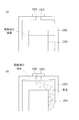
- FIG. 4A is a cross-sectional view showing a schematic configuration of the metal-air battery 3 according to the second embodiment.
- a space 63 is formed above the metal negative electrode 30 and the separator 50 in the negative electrode case 60.
- FIG. 4 (b) shows the metal-air battery 1 in which the space 63 is not formed for comparison.
- the liquid level of the electrolytic solution 40 which has risen during charging may exceed the upper surface of the negative electrode case 60. Then, if charging continues with the liquid surface of the electrolyte solution 40 exceeding the upper surface of the negative electrode case 60, dendrite grows above the negative electrode case 60, and a short circuit occurs between the negative electrode current collector 31 and the air electrode 20. May occur.
- the metal-air battery 3 by providing the space 63 between the upper end of the metal negative electrode 30 and the upper surface of the negative electrode case 60 inside the negative electrode case 60, electrolysis increased during charging.
- the liquid surface of the liquid 40 can be prevented from exceeding the upper surface of the negative electrode case 60.
- a short circuit between the negative electrode current collector 31 and the air electrode 20 due to the growth of dendrite above the negative electrode case 60 can be prevented.
- the height of the space 63 is H (mm)
- the volume of the lower region of the inside of the negative electrode case 60 and lower than the liquid surface of the electrolyte 40 at the time of standing is V1 (cm3)
- the negative electrode case The height H, the lower area volume V1 and the upper area volume V2 are inside the upper 60 when the upper area volume above the liquid surface of the electrolytic solution 40 at rest is V2 (cm3).
- H / (V1 / V2) When H / (V1 / V2) is less than 0.08, the liquid surface of the negative electrode case 60 may exceed the upper surface, and a short circuit may occur between the negative electrode current collector 31 and the air electrode 20.
- H / (V1 / V2) exceeds 2.0, in the metal-air battery 3, the volume occupied by the negative electrode case 60 increases, and the energy density of the battery decreases.
- FIG. 5 is a perspective view showing a state in which the metal negative electrode used in the metal-air battery according to Embodiment 3 is covered with a negative electrode case 60 and a separator 50.
- the third embodiment is characterized in that the liquid injection port 64 is covered with the liquid injection port 62 in the negative electrode case 60. Needless to say, the liquid injection port cover 64 is to be put on the liquid injection port 62 after the injection of the electrolytic solution in the metal-air battery is completed.
- the metal-air battery according to the third embodiment has basically the same structure as the metal-air battery 1 according to the first embodiment except that the liquid inlet 64 is covered with the liquid inlet 62.
- FIG. 6 (a) to 6 (c) show specific examples of the liquid injection port cover 64, and are cross-sectional views showing the negative electrode case 60 and the metal negative electrode 30 and the separator 50 in the inside thereof.
- FIG. 6A shows a configuration in which the liquid injection port cover 64 is a closed cover (for example, a resin cover or a sealing material).
- the liquid injection port 64 is not provided, the liquid level of the electrolyte 40 present outside the negative electrode case 60 rises above the liquid level in the stationary state during charging, and the liquid level exceeds the upper surface of the negative electrode case 60, The electrolytic solution 40 flows into the inside of the negative electrode case 60 from the liquid injection port 62, and through this path, a liquid junction in which the air electrode 20 and the metal negative electrode 30 inside the negative electrode case 60 are connected by the electrolytic solution occurs. A short circuit may occur between the metal negative electrode 30 and the air electrode 20 due to dendrite generated from the metal negative electrode 30 inside the negative electrode case 60 through the liquid junction.
- liquid injection port cover 64 by sealing the liquid injection port 62, liquid junction due to the flow of the electrolytic solution 40 into the liquid injection port 62 accompanying the liquid level rise of the electrolytic solution 40 during charging. It can prevent and can control a short circuit.
- FIG. 6 (b) shows the configuration in the case where the liquid inlet lid 64 is a gas-liquid separation membrane (for example, a water repellent porous membrane or the like).
- the gas-liquid separation film prevents the flow of the liquid, so that, as in the configuration of FIG. 6A, the electrolyte 40 to the injection port 62 accompanying the liquid level rise of the electrolyte 40 during charging. It is possible to prevent a liquid junction due to the inflow of water and to suppress a short circuit.
- the gas-liquid separation membrane allows the flow of gas, when hydrogen gas is generated by the self-corrosion reaction of the metal negative electrode 30 in the negative electrode case 60, the hydrogen gas is discharged from the liquid inlet 62 to the outside of the negative electrode case 60 It can be discharged. Thereby, expansion of the inside of negative electrode case 60 can be suppressed.
- FIG. 6C shows a configuration in the case where the liquid injection port cover 64 has a valve structure (such as a check valve) through which liquid or gas flows only from the inside to the outside of the negative electrode case 60.
- the short circuit can be suppressed as in the configuration of FIG. 6A, and the expansion of the inside of the negative electrode case 60 can be suppressed as in the configuration of FIG. 6B. Is possible.
- the metal ion concentration for example, zinc ion concentration
- the amount of electrolyte inside the negative electrode case 60 is increased by the osmotic pressure of the separator 50 on the negative electrode working surface.
- the level of the electrolyte 40 present outside the case 60 may be lowered and the air electrode active area may be lowered, whereby the discharge characteristics may be lowered.
- the liquid injection port cover 64 has a valve structure such as a check valve, the electrolyte 40 can be discharged from the inside of the negative electrode case 60 to the outside of the negative electrode case 60 through the liquid injection port 62.
- the liquid level inside and outside can be leveled, and the fall of a discharge characteristic can be controlled.
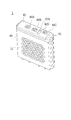
- FIG. 7 is a perspective view showing the appearance of the metal-air battery 1 according to Embodiment 4 of the present disclosure.
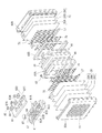
- FIG. 8 is an exploded perspective view showing each constituent member of the metal-air battery 1 in an exploded manner.
- the metal-air battery 1 includes a metal negative electrode 30 containing a metal serving as a negative electrode active material inside a battery case 80, a charging electrode 70 used as a positive electrode during charging, and a positive electrode during discharging.
- An air electrode 20 to be used and a separator 51 interposed between the charging electrode 70 and the air electrode 20 are accommodated. These are disposed in parallel with each other with at least a portion thereof immersed in the electrolyte solution (not shown) in the battery case 80.
- the metal negative electrode 30 is described as what integrated the negative electrode collector 31 by active material layer, and was integrated, as shown in FIG.
- the metal negative electrode 30 is sandwiched between two negative electrode case plates 60A and 60B, and is housed in the internal space of the negative electrode case 60 configured by joining the negative electrode case plates 60A and 60B.
- a packing 66 is disposed between the metal negative electrode 30 and the negative electrode case plates 60A and 60B.
- the negative electrode case 60 may be provided with a separator (not shown) for separating the charging electrode 70 and the metal negative electrode 30.
- the charging electrode 70 is disposed on the outer side surface of the negative electrode case plates 60A and 60B.
- a cylindrical liquid injection port 62 is provided on the negative electrode case 60 so as to protrude upward from the upper surface of the negative electrode case 60, and the inside and the outside of the negative electrode case 60 are conducted. The function of the injection port 62 will be described later.
- the side surface facing the charging electrode 70 or the air electrode 20 of the metal negative electrode 30 is covered with the separator 50 which can permeate
- a gas guiding rail 17 may be disposed between the charging electrode 70 and the separator 51.
- the gas guiding bar 17 is for forming a passage for releasing oxygen (bubbles) generated on the surface of the charging electrode 70 at the time of charging to the upper side of the electrolytic solution.
- the air electrode 20 is described in the state of being decomposed into a positive electrode current collector 20A, a catalyst layer 20B including catalyst particles having oxygen reducing ability, and a water repellent layer 20C as shown in FIG.
- the body 20A, the catalyst layer 20B and the water repellent layer 20C may be integrated together with the outer case plates 80A and 80B by a press or the like before the assembly of the metal-air battery 1.
- the outer case plates 80A and 80B are made of, for example, a resin, and the outer case plates 80A and 80B are joined to constitute the battery case 80.
- the air electrode 20 is provided so that oxygen gas contained in the atmosphere can be diffused.
- the air electrode 20 can be provided such that at least a portion of the surface of the air electrode 20 is exposed to the atmosphere.
- the air intake port 11 is provided in the outer case plates 80A and 80B of the battery case 80, and oxygen gas contained in the atmosphere via the air intake port 11 is present. It can diffuse into the cathode 20.
- the air electrode 20 is composed of the positive electrode current collector 20A, the catalyst layer 20B and the water repellent layer 20C.
- the catalyst layer 20B may be, for example, a conductive porous carrier and the porous carrier.
- an air electrode catalyst supported on the thus, it becomes possible to form a three-phase interface in which oxygen gas, water and electrons coexist on the air electrode catalyst, and the discharge reaction can be advanced.
- the water repellent layer 20C is provided to prevent the electrolyte from leaking from the air intake port 11 via the air electrode 20, and has a gas-liquid separation function.
- the upper edge portion of the battery case 80 is open, and the metal air battery 1 is provided with an inner lid 81 and an outer lid 82 which can close the upper edge portion of the battery case 80 so as to be attachable. That is, in the metal air battery 1, the case 10 is configured by the battery case 80, the inner lid 81 and the outer lid 82.
- FIG. 9 is a perspective view showing the battery case 80 in which only the inner lid 81 is mounted.
- the inner lid 81 is provided with terminal connection ports 81A to 81C, an air vent 81D and a liquid injection port 12.
- the terminal connection ports 81A to 81C are openings for connecting terminals to current collectors of the air electrode 20, the charging electrode 70, and the metal negative electrode 30, respectively.
- screw holes are formed in the bottoms of the terminal connection ports 81A to 81C.
- the vent 81D is a vent for releasing oxygen generated when the metal air battery 1 is charged to the outside of the battery.
- the injection port 12 is an opening for injecting the electrolytic solution into the assembled metal-air battery 1 (that is, in the battery case 80), and the injection port cap 83 (FIG. 9) after the injection of the electrolytic solution. (Not shown in the drawings).
- the outer lid 82 is provided with terminal connection ports 82A to 82C and a vent 82D.
- the terminal connection ports 82A to 82C are openings for connecting terminals to current collectors of the air electrode 20, the charging electrode 70, and the metal negative electrode 30, respectively.
- the terminal connection ports 82A to 82C communicate with the terminal connection ports 81A to 81C of the inner lid 81, respectively.
- the vent 82D is a vent for releasing oxygen generated when the metal air battery 1 is charged to the outside of the battery, and communicates with the vent 81D in the inner lid 81.
- Two metal terminal plates 84 are arranged at each of the terminal connection ports 81A to 81C and the terminal connection ports 82A to 82C to be communicated, and the charging electrode 70 and the metal negative electrode 30 are interposed between the two metal terminal boards 84.
- a connection extending from each current collector is disposed.
- the metal terminal plates 84 are fixed to the inner lid 81 by screws 85 to form terminals 86A to 86C.
- a load is connected between the terminal 86A and the terminal 86C (ie, between the air electrode 20 and the metal negative electrode 30).
- a power supply is connected between the terminal 86B and the terminal 86C (that is, between the charging electrode 70 and the metal negative electrode 30).
- a gas-liquid separation film 87A is disposed on the back surface side of the vent 82D of the outer lid 82.
- the gas-liquid separation film 87A does not inhibit the discharge of oxygen from the vent 81D and the vent 82D communicated with each other, and prevents only the leakage of the electrolyte.
- the gas-liquid separation film 87 B is disposed also on the top surface of the liquid injection port cap 83 that closes the liquid injection port 12. Thus, oxygen can be discharged from the liquid injection port 12 as well.
- FIG. 8 exemplifies a three-electrode type metal air secondary battery in which the air electrode 20 and the charging electrode 70 are selectively used as the positive electrode at the time of discharge and at the time of charge.
- the present disclosure is not limited to this, and if the catalyst having the oxygen reducing ability and the oxygen generating ability is used as the catalyst of the air electrode 20, the air electrode 20 can be used for the positive electrode both during discharging and charging. It may be a two-electrode type metal air secondary battery to be used. That is, in the two-pole type metal air secondary battery, the air electrode 20 also functions as a charging electrode at the time of charging.
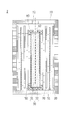
- FIG. 10 is a cross-sectional view of the metal-air battery 1 including the main surface of the metal negative electrode 30 (here, the arrangement surface of the current collector substantially at the center of the metal negative electrode 30).
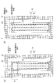
- FIG. 11 is a schematic cross-sectional view of the metal-air battery 1 according to the fourth embodiment, which corresponds to the cross section AA in FIG.
- the battery case 80 and the negative electrode case 60 are illustrated in FIG. 11, the electrodes (metal negative electrode 30, charging electrode 70, air electrode 20) are not shown. Further, although FIG.
- FIG 11 illustrates the gas-liquid separation membrane 87B as the gas-liquid separation membrane disposed on the upper surface of the battery case 80, this is compared with the gas-liquid separation membrane 87A. This is because the structure is more susceptible to the influence of the rise in the liquid level of the electrolytic solution, and therefore, when the rise in the liquid level of the electrolytic solution occurs, wetting by the electrolytic solution is likely to occur.
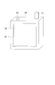
- FIG. 17 is a schematic cross-sectional view showing a part of a cross section of a conventional metal-air battery for explaining the conventional problems
- FIG. 17 (a) is a liquid level of the electrolyte of the metal-air battery in the stationary state.
- FIG. 17 (b) shows the electrolyte surface of the metal-air battery at the time of charging.
- the gas-liquid separation film 1003 which covers the battery housing 1000, the metal negative electrode 1001, electrolyte solution, the vent hole 1002, and the vent hole 1002 is shown, Is omitted.
- the vent 1002 is an opening for releasing oxygen generated in the vicinity of the charging electrode when charging the metal-air battery to the outside of the battery casing.
- the gas-liquid separation film 1003 is provided to prevent leakage of the electrolytic solution from the battery housing 1000 and to allow the oxygen to be discharged from the vent 1002.
- the gas-liquid separation film 1003 which has become wet does not function as a gas-liquid separation film, and oxygen can not be discharged to the outside in the battery housing 1000, and the internal pressure in the battery increases. As a result, the electrolyte leaks from the battery case 1000.
- the metal-air battery 1 according to the fourth embodiment is characterized in that the liquid injection port 62 is provided in the upper part of the negative electrode case 60 in order to solve the problems described above.
- the metal-air battery 1 can prevent the leakage of the electrolyte during charging by providing the liquid injection port 62.
- the upper end of the liquid injection port 62 is higher than the liquid level of the electrolytic solution in the stationary state shown in FIG. 11 (a).
- the liquid level of the electrolytic solution rises due to air bubbles generated near the charging electrode 70, but when the liquid level of the electrolytic solution finally reaches the upper end of the liquid injection port 62, the electrolysis is performed.
- the liquid is returned to the inside of the negative electrode case 60 from the injection port 62 by gravity, and a further rise in the liquid surface of the electrolytic solution is avoided.
- the electrolytic solution in the negative electrode case 60 penetrates to the charging electrode 70 side through the separator 50.
- the liquid level of the electrolyte rises above the upper end surface of the cylindrical liquid injection port 62 during charging.
- the air bubbles accumulated in the vicinity of the liquid surface may wet the gas-liquid separation film 87B or the air bubbles may be broken in the vicinity of the gas-liquid separation film 87B and the air-liquid separation film 87B may be wetted by the scattered electrolyte. It can be avoided.
- the gas-liquid separation film 87B does not stop functioning, and the internal pressure increase in the housing 10 can be prevented. As a result, it is possible to prevent the electrolytic solution from leaking from the joint of the battery case 80 of the metal-air battery 1 (for example, the joint of the outer case plates 80A and 80B and the inner lid 81).
- the liquid injection port 62 in the negative electrode case 60 is preferably located below the gas-liquid separation film 87 B (that is, below the liquid injection port 12). This is because the liquid level of the electrolytic solution at the time of charging is the lowest in the vicinity of the liquid injection port 62, and by positioning the liquid injection port 62 below the gas-liquid separation membrane 87B, the gas-liquid separation membrane 87B is affected by the electrolyte. It is because it can be most effectively prevented from getting wet.
- the liquid inlet 62 is positioned below the liquid inlet 12, it is not necessary to make the vertical center lines of the two coincide with each other, and they may be slightly shifted as shown in FIG.
- a concave portion 81F (see FIG. 10) is formed in the vicinity facing the liquid injection port 62, and the liquid injection port 62 is inserted into the concave portion 81F. It is preferable to set it as the structure arrange
- the liquid surface of the electrolytic solution is prevented from rising above the upper end surface of the cylindrical liquid injection port 62, the liquid surface of the electrolytic solution rises and the liquid passage is made by the electrolytic solution attached to the inner lid 80. It is also possible to prevent the liquid junction between the electrodes via this liquid passage, and also to prevent the short circuit.
- the upper space inside the negative electrode case 60 can be reduced by providing the protruding cylindrical injection port 62.
- the metal ion concentration (for example, zinc ion concentration) inside the negative electrode case 60 may increase, and the osmotic pressure of the separator 50 on the negative electrode working surface may increase the amount of electrolyte inside the negative electrode case 60 There is.
- the liquid level of the electrolyte present outside the negative electrode case 60 may be lowered, and the air electrode active area may be lowered, whereby the discharge characteristics may be deteriorated.
- the electrolytic solution inside the negative electrode case 60 passes through the injection port 62 and the negative electrode case 60 Since the amount of electrolytic solution required to discharge the electrolytic solution 40 from the inside to the outside of the negative electrode case 60 is small, it is possible to suppress the liquid level lowering outside the negative electrode case 60, and the discharge characteristic does not decrease. It is possible to suppress the decrease.
- the hydrogen gas when hydrogen gas is generated by the self-corrosion reaction of the metal negative electrode 30 in the negative electrode case 60, the hydrogen gas is discharged from the liquid inlet 62 to the outside of the negative electrode case 60. It can be discharged. Thereby, expansion of the inside of negative electrode case 60 can be suppressed.
- Comparative Example 1 in this experiment has all the same conditions as the metal-air battery 1 (Example 1) except that the liquid injection port is not provided in the negative electrode case 60.
- a power supply (5 V-5 A) was connected between the metal negative electrode 30 and the charging electrode 70, and charging was performed for 3 hours.
- the charging voltage at this time was lower than that of Comparative Example 1 and could be charged at a lower voltage in Example 1 (the charging voltage after 3 h of charging is 2.75 V in Comparative Example 1, 2.55 V in Example 1) ).
- the charging voltage after 3 h of charging is 2.75 V in Comparative Example 1, 2.55 V in Example 1
- leakage of the electrolyte was visually confirmed, in Comparative Example 1, leakage of the electrolyte (wet-out of the terminal surface of the inner lid 81) was confirmed, but in Example 1, leakage of the electrolyte was confirmed. It was not.
- the liquid injection port 62 and the liquid injection port 12 are provided on one end side (left end side in FIG. 10) of the metal air battery 1 in the longitudinal direction. There is. Therefore, air bubbles generated at the time of charging are induced to the vicinity of the liquid injection port 62 and the liquid injection port 12 along the lower surface of the inner lid 81 together with the electrolytic solution whose liquid level has risen (the moving direction is indicated by a solid arrow in FIG. 10). ), It is returned into the negative electrode case 60 from the liquid injection port 62.
- FIG. 13 shows the configuration of the metal-air battery 1 according to the fifth embodiment, and is a cross-sectional view including the main surface of the metal negative electrode 30 in the metal-air battery 1.
- the liquid injection port 62 and the liquid injection port 12 are provided on one end side (the left end side in FIG. 13) of the metal air battery 1 in the longitudinal direction.
- the lower surface of the inner lid 81 is an inclined surface which is inclined along the longitudinal direction. This inclined surface is an inclined surface which rises from the end on the side where the liquid inlet 62 and the liquid inlet 12 are not disposed toward the end on the side where the liquid inlet 62 and the liquid inlet 12 are disposed. It is done.
- the air bubbles generated at the time of charging are guided to the vicinity of the liquid inlet 62 and the liquid inlet 12 along the lower surface of the inner lid 81 together with the electrolyte rising the liquid level.
- the moving direction is shown by a solid arrow in FIG. 13).
- the lower surface of the inner lid 81 is an inclined surface along the longitudinal direction, the bubbles in the vicinity of the liquid surface are induced to reduce the number of bubbles while growing smoothly. Therefore, the number of air bubbles is sufficiently reduced near the liquid injection port 12, and it is possible to prevent a large number of air bubbles from being blown around the gas-liquid separation film 87B.
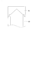
- FIG. 14 shows the configuration of the metal-air battery 1 according to Embodiment 6, and is a cross-sectional view showing the shape of the lower surface of the inner lid 81 in the short direction.
- the lower surface of the inner lid 81 is formed in an inverted V-shaped inclined surface along the short direction.
- the electrolytic solution whose liquid level has risen is guided along the lower surface of the inner lid 81 to the vicinity of the liquid injection port 62 and the liquid injection port 12.
- the lower surface of the inner lid 81 is an inverted V-shaped inclined surface along the lateral direction, air bubbles in the vicinity of the liquid surface gather near the center in the lateral direction, and grow smoothly. While being induced to reduce the number of bubbles. Therefore, the number of air bubbles is sufficiently reduced near the liquid injection port 12, and it is possible to prevent a large number of air bubbles from being blown around the gas-liquid separation film 87B.
- the metal-air battery 1 according to the seventh embodiment is characterized in that the frictional resistance of the lower surface of the inner lid 81 is reduced.
- the lower surface of the inner cover 81 is polished or the inner surface of the inner cover 81 is formed by injection molding (for example, the surface roughness Ra is 0.2 ⁇ m or less). Can be considered.
- the lower surface of the inner lid 81 may be subjected to surface treatment to reduce the frictional resistance of the lower surface of the inner lid 81. Examples of the surface treatment in this case include water repellent finishing such as Teflon (registered trademark) processing.
- the electrolytic solution whose liquid level has risen is guided along the lower surface of the inner lid 81 to the vicinity of the liquid injection port 62 and the liquid injection port 12.
- the frictional resistance of the lower surface of the inner lid 81 is reduced, the bubbles in the vicinity of the liquid surface are induced to reduce the number of bubbles while growing smoothly. Therefore, the number of air bubbles is sufficiently reduced near the liquid injection port 12, and it is possible to prevent a large number of air bubbles from being blown around the gas-liquid separation film 87B.
- Embodiments 4 to 7 above although there are differences in the shape of the lower surface of the inner lid 81 and the presence or absence of surface treatment, the mobility of air bubbles in the vicinity of the liquid surface of the electrolytic solution due to this difference was compared. In addition, as a comparative example, the mobility of air bubbles in the case where the liquid injection port 62 was not provided in the negative electrode case 60 was also confirmed.
- the generated air bubbles did not move while staying on the liquid surface of the electrolytic solution, and did not reach the liquid injection port 62.
- the lower surface of the inner lid 81 is a horizontal surface, and the surface treatment is not performed (surface roughness Ra is 3.2 ⁇ m or more)
- the generated bubbles form a cylindrical injection port together with the electrolyte. It was confirmed to move to 62. At this time, the arrival time from the generation of air bubbles to the liquid injection port 62 was 10 seconds or more.
- the configuration of the fifth embodiment (the lower surface of the inner lid 81 is an inclined surface along the longitudinal direction), the configuration of the sixth embodiment (an inverted V-shaped inclined surface where the lower surface of the inner lid 81 is along the shorter direction),
- the configuration of the seventh embodiment (surface treatment on the lower surface of the inner lid 81)
- the arrival time from the generation of air bubbles to the liquid injection port 62 is less than 10 seconds, and the movement of the air bubbles is promoted as compared with the configuration of the fourth embodiment.
- the shorter the arrival time from the generation of air bubbles to the liquid injection port 62 the smaller the number of air bubbles on the liquid surface.
Landscapes
- Chemical & Material Sciences (AREA)
- Chemical Kinetics & Catalysis (AREA)
- Electrochemistry (AREA)
- General Chemical & Material Sciences (AREA)
- Engineering & Computer Science (AREA)
- Materials Engineering (AREA)
- Manufacturing & Machinery (AREA)
- Hybrid Cells (AREA)
- Filling, Topping-Up Batteries (AREA)
Abstract
金属空気電池は、負極活物質となる金属を含む金属負極と、空気極とを、筐体の内部で電解液中に少なくとも一部が浸漬した状態で対向配置してなる。金属負極は、筐体内で負極ケースの内部に収納されている。負極ケースの側面には、金属負極と空気極との間を隔離するセパレータが配置されている。負極ケースの上面には、負極ケース内部と負極ケース外部とを連通する注液口が設けられている。
Description
本開示は、金属空気電池に使用される電池筐体、金属空気電池および金属空気電池の製造方法に関する。
金属空気電池は、空気極(正極)と、金属負極(負極)と、電解質層(電解液)とを備えて構成されている。また、金属空気二次電池には、放電時または充電時のデンドライトによる短絡防止のため、金属負極を被覆材とセパレータとで覆う構成が提案されている(特許文献1)。
図15は、特許文献1などに示される従来の金属空気二次電池の概略構成を示す断面図である。図16は、図15の金属空気二次電池において使用される金属負極を被覆材およびセパレータで覆った状態を示す斜視図である。
図15に示す金属空気二次電池は、筐体100内に空気極110と金属負極120とを配置しており、空気極110および金属負極120は電解液130中に浸漬した状態で互いに平行に配置される。
金属負極120は、負極集電体121を活物質層122で挟み込んだ構成とされている。また、金属負極120の両側にはセパレータ(例えばアニオン膜)140が配置され、金属負極120およびセパレータ140は共に負極ケース(被覆材)150内に収納されている。負極ケース150の両側面には開口151が設けられており、電解液130はセパレータ140を浸透して負極ケース150の内部に注入されるようになっている。
空気極110は、筐体100内の両側面に配置されるが、空気極110の表面の一部が大気に曝されるように筐体100の側板には空気取込口111が設けられている。さらに、筐体100の上面には、筐体100内に電解液130を注液するための注液口112が設けられている。
図15に示す従来の金属空気二次電池では、注液口112から電解液130を注液した後、電解液130がセパレータ140を浸透して負極ケース150内に注入されるのに時間がかかるといった問題がある。すなわち、金属空気電池の作製時における電解液の注液時間が長くなる。
尚、金属空気一次電池の場合でも、空気極と金属負極が接触(短絡)しないようにセパレータは必要であり、被覆材は負極端部の過剰放電を防止するために必要であるため、同様の課題は、金属空気二次電池に限らず、金属空気一次電池でも発生する。
本開示は、上記課題に鑑みてなされたものであり、負極ケース内部に収納された金属負極への電解液の注液時間を短縮可能な金属空気電池を提供することを目的とする。
上記の課題を解決するために、本開示の電池筐体は、筐体内部に、負極活物質となる金属を含む金属負極と、金属負極に対向配置された空気極と、を備えた電池筐体であって、金属負極は、筐体内で負極ケースに収納され、負極ケースの側面には、金属負極と空気極との間を隔離するセパレータが配置され、負極ケースの上面には、負極ケース内部と負極ケース外部とを連通する開口を有することを特徴としている。
本開示の電池筐体および金属空気電池は、筐体内への電解液の注液工程において、電解液は負極ケースに設けられた注液口から負極ケース内にも直接注入される。したがって、セパレータからの液浸透のみで負極ケースに電解液が注入される従来の金属空気電池に比べ、電解液の注液時間を大幅に短縮することができるといった効果を奏する。
〔実施の形態1〕
以下、本開示の実施の形態について、図面を参照して詳細に説明する。
以下、本開示の実施の形態について、図面を参照して詳細に説明する。
図1は、本実施の形態1に係る金属空気電池1の概略構成を示す断面図である。図2は、図1の金属空気電池1において使用される金属負極を被覆材およびセパレータで覆った状態を示す斜視図である。
図1に示す金属空気電池1は、筐体10内に空気極20と金属負極30とを配置しており、空気極20および金属負極30は電解液40中に浸漬した状態で互いに平行に配置される。
金属負極30は、金属元素を含む活物質からなる電極であり、放電時には活物質の酸化反応が、充電時には還元反応が起こる。金属元素としては、亜鉛、リチウム、ナトリウム、カルシウム、マグネシウム、アルミニウム、鉄などが用いられる。図1では、金属負極30は、負極集電体31を活物質層32で挟み込み一体化したものとして記載されている。
また、金属負極30の両側にはセパレータ(例えばアニオン伝導膜)50が配置されている。セパレータ50は、電極間で電子伝導経路が形成され短絡することを防ぐもので、電子的に絶縁性の材料で形成される。すなわち、セパレータ50は、例えば、充電時に金属負極30で還元析出した金属デンドライトが、空気極20に到達し、短絡することを抑制する。セパレータ50としては、当該分野の一般的な材料が用いることができ、多孔性樹脂シート、アニオン伝導膜やイオン交換膜などの固体電解質シートが利用される。電極間に配置されたセパレータ50を介して水酸化物イオンなどのイオン伝導が起こる。セパレータ50にアニオン伝導膜を用いた場合、水酸化物イオンはセパレータ50を透過し、[Zn[(OH)4]2-などイオン半径の大きいアニオンはセパレータ50を透過しないように設計することも可能である。
空気極20は、筐体10内の両側面に配置されるが、空気極20の表面の一部が大気に曝されるように筐体10の側板には空気取込口11が設けられている。さらに、筐体10の上面には、筐体10内に電解液40を注液するための注液口12が設けられている。図1では詳細な図示を省略しているが、空気極20は、集電体、触媒層および撥水層等により構成される。触媒層は、例えば、導電性の多孔性担体と、該多孔性担体に担持された酸素還元触媒とを含んでいてもよい。これにより、酸素還元触媒上において、酸素ガスと水と電子とが共存する三相界面を形成することが可能になり、放電反応を進行させることができる。また、触媒層は、さらに酸素発生触媒を含んでいてもよい。これにより、酸素発生触媒上において、酸素ガスと水と電子とが共存する三相界面を形成することが可能になり、充電反応を進行させることができる。また、触媒層は、酸素還元能および酸素発生能の両方を有する触媒であってもよい。また、撥水層は、空気取込口11から空気極20を介した電解液の漏洩を防ぐために設けられており、気液分離機能を有する。
また、金属空気電池1では、金属負極30およびセパレータ50は共に負極ケース(被覆材)60内に収納されている。負極ケース60の両側面には開口61が設けられており、電解液40は開口61からセパレータ50を浸透して負極ケース60の内部に注入されるようになっている。さらに、負極ケース60の上面には注液口62が設けられている。ここで、金属負極30を構成する負極集電体31は負極ケース60の上端から負極ケース60外部に突出している。負極集電体31の負極ケース60の外部に突出している領域の表面は絶縁被覆(図示せず)で覆われ、負極集電体31と電解液40とが直接接触しない構成としてもよい。
電解液40は、溶媒に電解質が溶解しイオン導電性を有する液体である。電解液40の種類は、金属電極に含まれる電極活物質の種類によって異なるが、水溶媒を用いた電解液(電解質水溶液)であってもよい。例えば、亜鉛空気電池、アルミニウム空気電池、鉄空気電池の場合、電解液40には、水酸化ナトリウム水溶液、水酸化カリウム水溶液などのアルカリ性水溶液を用いることができ、マグネシウム空気電池の場合、電解液40には塩化ナトリウム水溶液を用いることができる。リチウム空気電池の場合、有機性の電解液40を用いることができる。電解液40には、電解質以外の有機添加物や無機添加物が添加されても良く、高分子添加物によりゲル化されていてもよい。
本実施の形態1に係る金属空気電池1は、その構成部材(筐体や電極等)を組み立てた後、注液口12から電解液40が注液され、注液後は注液口12がキャップ(図示せず)等で閉じられる。この注液工程において、電解液40は注液口62から負極ケース60内にも直接注入される。したがって、セパレータからの液浸透のみで負極ケースに電解液が注入される従来の金属空気電池に比べ、電解液40の注液時間を大幅に短縮することができる。尚、本実施の形態1および後述する実施の形態2-4では、電解液40を注液する前の構成部材の組立構造物が特許請求の範囲に記載の電池筐体に相当する。
尚、図1に示す金属空気電池1では、放電時と充電時との両方で正極に空気極20を使用する2極方式の金属空気二次電池を例示しているが、本開示はこれに限定されるものではなく、金属空気一次電池であっても、または3極方式の金属空気二次電池であっても本開示は適用可能である。金属空気一次電池では、例えば、空気極の触媒層に酸素還元触媒を含み、酸素発生触媒能を含まなくてもよい。図3は、3極方式の金属空気二次電池2の概略構成を示す断面図である。
図3に示す金属空気二次電池2では、負極ケース60と空気極20との間に充電極70が配置され、さらに空気極20と充電極70との間にセパレータ51が配置される。3極方式の金属空気二次電池2では、放電時には空気極20が正極として用いられ、充電時には充電極70が正極として用いられる。3極方式の金属空気二次電池の空気極では、触媒層に酸素還元能触媒を含めばよい。また、充電極70は、酸素発生能を有する電極が用いることができ、例えば、Ni電極やステンレス電極が用いられる。充電極70は、Niやステンレスのメッシュ、エキスパンドメタル、パンチングメタル、金属粒子や金属繊維の焼結体、発泡金属などを使用することで多孔性とすることができる。また、充電極70は、表面に充電反応を促進する触媒粒子を更に備えていてもよい。
〔実施の形態2〕
本実施の形態2では、デンドライトによる短絡をより防止できる金属空気電池の構成について説明する。
本実施の形態2では、デンドライトによる短絡をより防止できる金属空気電池の構成について説明する。
図4(a)は、本実施の形態2に係る金属空気電池3の概略構成を示す断面図である。図4(a)における金属空気電池3では、負極ケース60の内部で、金属負極30およびセパレータ50の上方に空間63が形成されている。また、図4(b)には、比較のために空間63の形成されていない金属空気電池1を示している。
金属空気電池の充電時には、充電極(または空気極)の近傍で酸素が発生し、発生した酸素は電解液内で気泡となる。この気泡により、充電時の負極ケース60の外部に存在する電解液の液面は、静置状態時の液面よりも上昇する。
図4(b)に示す比較例(金属空気電池1)では、充電時に上昇した電解液40の液面が負極ケース60の上面を越えてしまう場合がある。そして、電解液40の液面が負極ケース60の上面を越えた状態で充電を続けると、負極ケース60よりも上部でデンドライトが成長し、負極集電体31と空気極20との間で短絡が生じる虞がある。
これに対し、本実施の形態2に係る金属空気電池3では、負極ケース60の内部に金属負極30の上端と負極ケース60の上面との間に空間63を設けることにより、充電時に上昇した電解液40の液面が負極ケース60の上面を越えることを防止できる。その結果、負極ケース60よりも上部でのデンドライトの成長による、負極集電体31と空気極20との間の短絡を防止できる。
金属空気電池3において、空間63の高さをH(mm)、負極ケース60の内部であって、静置時の電解液40の液面より下部の下部領域体積をV1(cm3)、負極ケース60の内部であって、静置時の電解液40の液面より上部の上部領域体積をV2(cm3)とするとき、高さH、下部領域体積V1および上部領域体積V2は、
0.08<(H/(V1/V2))<2.0
を満たすことが好ましく、
0.3<(H/(V1/V2))<1.5
を満たすことがより好ましい。
0.08<(H/(V1/V2))<2.0
を満たすことが好ましく、
0.3<(H/(V1/V2))<1.5
を満たすことがより好ましい。
H/(V1/V2)が0.08を下回る場合は、負極ケース60の液面が上面を超える虞があり、負極集電体31と空気極20との間で短絡が生じる場合がある。H/(V1/V2)が2.0を上回る場合は、金属空気電池3において、負極ケース60の占める体積が大きくなり、電池のエネルギー密度が低下する。
〔実施の形態3〕
本実施の形態3では、デンドライトによる短絡をより防止できる金属空気電池の他の構成について説明する。
本実施の形態3では、デンドライトによる短絡をより防止できる金属空気電池の他の構成について説明する。
図5は、本実施の形態3に係る金属空気電池において使用される金属負極を負極ケース60およびセパレータ50で覆った状態を示す斜視図である。図5に示すように、本実施の形態3では、負極ケース60における注液口62に注液口蓋64を被せる構造を特徴とする。無論、注液口蓋64は、金属空気電池における電解液の注液が完了した後に、注液口62に被せられるものである。尚、本実施の形態3に係る金属空気電池は、注液口62に注液口蓋64を被せる以外は、基本的に実施の形態1における金属空気電池1と同様の構造である。
図6(a)~(c)は、注液口蓋64の具体例を示すものであり、負極ケース60と、その内部の金属負極30およびセパレータ50とを示す断面図である。
図6(a)は、注液口蓋64を密閉蓋(例えば、樹脂蓋や封止材など)とした場合の構成を示す。注液口蓋64が無い場合、充電時には、負極ケース60の外部に存在する電解液40の液面は、静置状態時の液面よりも上昇し、液面が負極ケース60の上面を超え、注液口62から、負極ケース60内部へと電解液40が流れ込み、この経路を通じ、空気極20と負極ケース60内部の金属負極30とが電解液でつながる液絡が生じる。この液絡を介して、負極ケース60内部の金属負極30から生じるデンドライトにより、金属負極30と空気極20との間で短絡が発生する虞がある。一方、注液口蓋64を備える構成では、注液口62に密閉蓋をすることで、充電時における電解液40の液面上昇に伴う注液口62への電解液40の流れ込みによる液絡を防止でき、短絡を抑制できる。
図6(b)は、注液口蓋64を気液分離膜(例えば、撥水性多孔膜など)とした場合の構成を示す。この構成では、気液分離膜が液体の流通を防止することで、図6(a)の構成と同様に、充電時における電解液40の液面上昇に伴う注液口62への電解液40の流れ込みによる液絡を防止でき、短絡を抑制できる。さらに、気液分離膜は気体の流通は許容するため、負極ケース60内で金属負極30の自己腐食反応により水素ガスが発生した場合に該水素ガスを注液口62から負極ケース60の外部に排出することができる。これにより、負極ケース60内部の膨張を抑制できる。
図6(c)は、注液口蓋64を負極ケース60の内部から外部にのみ液体もしくは気体が流れる弁構造(逆止弁など)とした場合の構成を示す。この構成では、図6(a)の構成と同様に短絡を抑制でき、図6(b)の構成と同様に負極ケース60内部の膨張を抑制でき、加えて、放電時の液面バランスの保持が可能となる。放電時には、負極ケース60内部の金属イオン濃度(例えば、亜鉛イオン濃度)が上昇することで、負極作用面にあるセパレータ50の浸透圧により、負極ケース60内部の電解液量が増加する結果、負極ケース60の外部に存在する電解液40の液面が低下し空気極作用面積が下がることで放電特性が低下することがある。注液口蓋64を逆止弁のような弁構造にした場合には、注液口62を介して負極ケース60内部から負極ケース60外部へ電解液40を排出することができるため、負極ケース60内外の液面をレベリングすることができ、放電特性の低下を抑制することができる。
〔実施の形態4〕
図7は、本開示の実施の形態4に係る金属空気電池1の外観を示す斜視図である。また、図8は、金属空気電池1の各構成部材を分解して示す分解斜視図である。
図7は、本開示の実施の形態4に係る金属空気電池1の外観を示す斜視図である。また、図8は、金属空気電池1の各構成部材を分解して示す分解斜視図である。
金属空気電池1は、図7および図8に示すように、電槽80の内部に、負極活物質となる金属を含む金属負極30と、充電時に正極として用いる充電極70と、放電時に正極として用いる空気極20と、充電極70と空気極20との間に介装されたセパレータ51とが収納されている。これらは、電槽80内の電解液(図示せず)中に少なくとも一部が浸漬した状態で互いに平行に配置される。
金属負極30は、図8に示すように、負極集電体31を活物質層で挟み込み一体化したものとして記載されている。また、金属負極30は、2枚の負極ケース板60A,60Bに挟み込まれ、負極ケース板60A,60Bを接合して構成される負極ケース60の内部空間に収納される構成となる。金属負極30と負極ケース板60A,60Bとの間にはパッキン66が配置されている。また、負極ケース60には、充電極70と金属負極30を隔てるセパレータ(図示省略)を設けてもよい。
充電極70は、負極ケース板60A,60Bの外側面に配置される。また、負極ケース60には、筒状の注液口62が負極ケース60の上面から上方に突出するように設けられ、負極ケース60の内部と外部とを導通させている。注液口62の機能については後述する。また、金属負極30の充電極70または空気極20と対向しているそれぞれの側面は、電解液が浸透可能なセパレータ50で覆われていることが好ましい。
充電極70とセパレータ51との間には、ガス案内用桟17が配置されていてもよい。ガス案内用桟17は、充電時に充電極70の表面で発生する酸素(気泡)を電解液の上方へ逃がすための通路を形成するためのものである。
空気極20は、図8に示すように、正極集電体20A、酸素還元能を有する触媒粒子を含む触媒層20Bおよび撥水層20Cに分解された状態で記載されているが、正極集電体20A、触媒層20Bおよび撥水層20Cは、金属空気電池1の組立の前に、外部ケース板80A,80Bと共にプレス等によって一体化されていてもよい。外部ケース板80A,80Bは、例えば樹脂によって形成されており、外部ケース板80A,80Bが接合されて電槽80を構成する。
また、空気極20は、大気に含まれる酸素ガスが拡散できるように設けられる。例えば、空気極20は、少なくとも空気極20の表面の一部が大気に曝されるように設けることができる。図7及び図8に示した金属空気電池1では、電槽80の外部ケース板80A,80Bに空気取込口11を設けており、空気取込口11を介して大気に含まれる酸素ガスが空気極20中に拡散できる。
空気極20は、上述したように、正極集電体20A、触媒層20Bおよび撥水層20Cにより構成されているが、触媒層20Bは、例えば、導電性の多孔性担体と、該多孔性担体に担持された空気極触媒とを含んでいてもよい。これにより、空気極触媒上において、酸素ガスと水と電子とが共存する三相界面を形成することが可能になり、放電反応を進行させることができる。また、撥水層20Cは、空気取込口11から空気極20を介した電解液の漏洩を防ぐために設けられており、気液分離機能を有する。
電槽80の上縁部は開放されており、金属空気電池1には、電槽80の上縁部を閉塞する内蓋81及び外蓋82が装着可能に設けられている。すなわち、金属空気電池1では、電槽80と内蓋81及び外蓋82とによって筐体10が構成される。図9は、電槽80に内蓋81のみが装着された状態を示す斜視図である。
内蓋81には、端子接続口81A~81C、通気口81Dおよび注液口12が設けられている。端子接続口81A~81Cは、空気極20、充電極70および金属負極30のそれぞれの集電体に端子を接続するための開口である。また、端子接続口81A~81Cの底部には、それぞれネジ孔が形成されている。通気口81Dは、金属空気電池1の充電時に発生する酸素を電池外に逃がすための通気孔である。注液口12は、組み立てられた金属空気電池1内(すなわち、電槽80内)に電解液を注液するための開口であり、電解液の注液後は注液口キャップ83(図9では不図示)によって閉塞されるようになっている。
外蓋82には、端子接続口82A~82Cおよび通気口82Dが設けられている。端子接続口82A~82Cは、空気極20、充電極70および金属負極30のそれぞれの集電体に端子を接続するための開口である。また、端子接続口82A~82Cは、内蓋81における端子接続口81A~81Cのそれぞれに連通する。通気口82Dは、金属空気電池1の充電時に発生する酸素を電池外に逃がすための通気孔であり、内蓋81における通気口81Dに連通する。
連通される端子接続口81A~81Cおよび端子接続口82A~82Cのそれぞれには、2枚の金属端子板84が配置され、2枚の金属端子板84の間に充電極70および金属負極30のそれぞれの集電体から延設された接続部が配置される。これらの金属端子板84がネジ85にて内蓋81に固定されることで端子86A~86Cが構成される。放電時には、端子86Aと端子86Cとの間(すなわち空気極20と金属負極30との間)に負荷が接続される。また、充電時には、端子86Bと端子86Cとの間(すなわち充電極70と金属負極30との間)に電源が接続される。
外蓋82の通気口82Dの裏面側には、気液分離膜87Aが配置される。気液分離膜87Aは、連通される通気口81Dおよび通気口82Dからの酸素の排出を阻害せず、電解液の漏洩のみを防止する。また、金属空気電池1では、注液口12を塞ぐ注液口キャップ83の上面にも気液分離膜87Bが配置されている。これにより、注液口12からも酸素の排出が行えるようになっている。
尚、図8では、放電時と充電時とで正極に空気極20と充電極70とを使い分ける3極方式の金属空気二次電池を例示している。しかしながら、本開示はこれに限定されるものではなく、空気極20の触媒に酸素還元能および酸素発生能を有する触媒を利用すれば、放電時と充電時との両方で正極に空気極20を使用する2極方式の金属空気二次電池であってもよい。すなわち、2極方式の金属空気二次電池では、空気極20が充電時の充電極としても機能する。
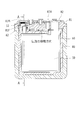
以上が本実施の形態4に係る金属空気電池1の基本構成であるが、続いて、金属空気電池1の特徴的構成とその作用効果とについて図10および図11を参照して説明する。図10は、金属空気電池1において、金属負極30の主面(ここでは、金属負極30のほぼ中央にある集電体の配置面)を含む断面図である。図11は、本実施の形態4に係る金属空気電池1の概略断面図であり、図10におけるA-A断面に対応する。尚、図11では、電槽80と負極ケース60とを図示しているが、電極(金属負極30、充電極70、空気極20)の図示は省略している。また、図11では、電槽80の上面に配置された気液分離膜として、気液分離膜87Bを図示しているが、これは、気液分離膜87Aに比べて気液分離膜87Bの方が電解液の液面上昇の影響を受けやすい構造にあるため、電解液の液面上昇が生じた時に電解液による濡れが生じ易いためである。
図17は、従来の課題を説明するための従来の金属空気電池の断面の一部を示す模式断面図であり、図17(a)は静置状態時の金属空気電池の電解液の液面を示し、図17(b)は充電時の金属空気電池の電解液面を示す。尚、図17では、電池構造を簡略に示すため、電池筐体1000、金属負極1001、電解液、通気口1002、通気口1002を覆う気液分離膜1003を示し、空気極および補助極の図示は省略している。
通気口1002は、金属空気電池の充電時に充電極近傍で発生する酸素を電池筐体外に逃がすための開口である。気液分離膜1003は、電池筐体1000からの電解液の漏れを防止し、かつ、通気口1002から酸素の導出を可能にするために設けられている。
図17(b)に示すように、充電時において充電極近傍で発生した酸素は、電解液内で気泡となり液面へと上昇する。そのため、電解液の液面が上昇する。つまり、図17(a)に示す静置状態に比べ、図17(b)に示す充電時では電解液の液面が高くなる。その結果、電解液の液面が気液分離膜1003に近づき、電解液の液面に蓄積された気泡が割れて、気液分離膜1003が電解液に濡れてしまうことがある。
濡れてしまった気液分離膜1003は、気液分離膜として機能しなくなり、電池筐体1000内で酸素を外部に排出できなくなり、電池内の内圧が上昇する。その結果、電池筐体1000から電解液が漏洩する原因となる。
本実施の形態4に係る金属空気電池1は、上記に記載した課題に対して、負極ケース60の上部において注液口62が設けられたことを特徴としている。金属空気電池1は、注液口62を設けたことにより、充電時における電解液の漏洩を防止できる。
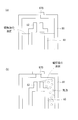
図11に示す金属空気電池1の構造では、図11(a)に示す静置状態時において、注液口62の上端は電解液の液面より高くなっている。図11(b)に示す充電時には、充電極70の近傍で発生する気泡によって電解液の液面が上昇するが、最終的に電解液の液面が注液口62の上端まで到達すると、電解液は重力によって注液口62から負極ケース60の内部に戻され、それ以上の電解液の液面上昇が回避される。尚、負極ケース60内の電解液は、セパレータ50を介して充電極70側へ浸透していく。
すなわち、金属空気電池1の構造では、負極ケース60に筒状の注液口62を設けたことにより、充電時に、電解液の液面が筒状の注液口62の上端面以上に上昇することを防ぐ。そのため、液面近傍に蓄積された気泡によって気液分離膜87Bが濡れたり、あるいは、気液分離膜87Bの近傍で気泡が割れ、飛び散った電解液によって気液分離膜87Bが濡れたりすることを回避できる。そして、気液分離膜87Bが電解液によって濡れることを回避したことにより、気液分離膜87Bが機能しなくなることはなく、筐体10内の内圧上昇を防止できる。その結果、金属空気電池1の電槽80の継ぎ目(例えば、外部ケース板80A,80Bと内蓋81との継ぎ目)などから電解液が漏洩することを防止できる。
また、金属空気電池1においては、負極ケース60における注液口62は、気液分離膜87Bの下方(すなわち注液口12の下方)に位置することが好ましい。これは、充電時における電解液の液面は注液口62の近傍で最も低くなり、注液口62を気液分離膜87Bの下方に位置させることで、気液分離膜87Bが電解液によって濡れることを最も効果的に防止できるためである。尚、注液口62を注液口12の下方に位置させるにあたって、両者の垂直方向の中心線は必ずしも一致させる必要は無く、図10に示すように若干ずれていてもよい。
また、内蓋81の下面(すなわち、筐体の上内面)においては、注液口62と対向する付近に凹部81F(図10参照)を形成し、注液口62を凹部81Fに挿入して配置する構成とすることが好ましい。この構成では、液面上昇した電解液が注液口62に流れ込む前に内蓋81に衝突するため、この衝突によって液面の気泡がつぶれて酸素の排出が促進される。
さらに、電解液の液面が筒状の注液口62の上端面以上に上昇することが防がれるので、電解液の液面が上昇することで内蓋80に付着した電解液により液路が形成され、この液路を介した電極間の液絡も防ぐことができ、短絡防止にも効果を奏する。
また、本実施の形態4に係る金属空気電池1では、突出した筒状の注液口62を設けることで、負極ケース60内部の上部空間を少なくすることができる。放電時には、負極ケース60内部の金属イオン濃度(例えば、亜鉛イオン濃度)が上昇することで、負極作用面にあるセパレータ50の浸透圧により、負極ケース60の内部の電解液量が増加する可能性がある。その結果、負極ケース60外部に存在する電解液の液面が低下し、空気極作用面積が下がることで放電特性が低下することがある。負極ケース60内部の上部空間が少なくなることで、放電時の負極ケース60内部の電解液40の液面上昇の際に、負極ケース60内部の電解液が注液口62を介して負極ケース60内部から負極ケース60外部へ電解液40を排出するのに必要な電解液量が少なく済むため、負極ケース60外部における液面低下を抑制でき、空気極作用面積が減少することなく、放電特性の低下を抑制することができる。
また、本実施の形態4に係る金属空気電池1では、負極ケース60内で金属負極30の自己腐食反応により水素ガスが発生した場合に該水素ガスを注液口62から負極ケース60の外部に排出することができる。これにより、負極ケース60内部の膨張を抑制できる。
本実施の形態1に係る金属空気電池1(実施例1)と比較例1とにおいて、充電および放電実験を行い、図12のグラフに示す結果が得られた。尚、この実験における比較例1は、負極ケース60において注液口が設けられていない以外は、全て金属空気電池1(実施例1)と同一の条件とされている。
先ず、充電時においては、金属負極30-充電極70間に電源(5V-5A)を接続し、3時間の充電を行った。この時の充電電圧は、比較例1に比べて実施例1の方が低い電圧で充電可能であった(充電3h後の充電電圧が比較例1では2.75V、実施例1では2.55V)。また、目視にて電解液の漏洩を確認したところ、比較例1では電解液の漏洩(内蓋81の端子表面の液濡れ)が確認されたが、実施例1では電解液の漏洩は確認されなかった。
次に、放電時においては、金属負極30-空気極20間に負荷(5V-5A)を接続し、電極の評価基準電流30mA/cm2が常に一定となるように負荷を可変で設定しながら放電を行った。また、放電電圧が0.6V以下になった時点で寿命と判断した。この時の放電電圧は、比較例1に比べて実施例1の方が全体的に高い電圧で放電可能であり、また実施例1の方が寿命が長いことも確認された(放電寿命までの放電時間が比較例1では1.5h、実施例1では2.7h)。
上記の実験結果は、電解液の漏洩の有無によって、電池性能に差が生じたものと考えられる。すなわち、比較例1では、電解液の漏洩によって充電電圧は高く、放電電圧は低くなるが、実施例1では、電解液の漏洩が無いため、比較例1に比べて充電電圧を低く、放電電圧を高くすることができる。
〔実施の形態5〕
実施の形態4に係る金属空気電池1では、図10に示すように、注液口62および注液口12が金属空気電池1の長手方向の一端側(図10では左端側)に設けられている。このため、充電時に発生した気泡は、液面上昇した電解液と共に内蓋81の下面に沿って注液口62および注液口12付近まで誘導され(移動方向を図10に実線矢印にて示す)、注液口62から負極ケース60内に戻される。
実施の形態4に係る金属空気電池1では、図10に示すように、注液口62および注液口12が金属空気電池1の長手方向の一端側(図10では左端側)に設けられている。このため、充電時に発生した気泡は、液面上昇した電解液と共に内蓋81の下面に沿って注液口62および注液口12付近まで誘導され(移動方向を図10に実線矢印にて示す)、注液口62から負極ケース60内に戻される。
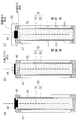
図13は、本実施の形態5に係る金属空気電池1の構成を示すものであり、金属空気電池1における金属負極30の主面を含む断面図である。図13に示す金属空気電池1では、注液口62および注液口12が金属空気電池1の長手方向の一端側(図13では左端側)に設けられている。さらに、図13に示す金属空気電池1では、内蓋81の下面が長手方向に沿って傾斜する傾斜面とされている。この傾斜面は、注液口62および注液口12が配置されていない側の端部から注液口62および注液口12が配置されている側の端部に向けて上昇する傾斜面とされている。
本実施の形態5に係る金属空気電池1でも、充電時に発生した気泡は、液面上昇した電解液と共に内蓋81の下面に沿って、注液口62および注液口12付近まで誘導される(移動方向を図13に実線矢印にて示す)。この時、内蓋81の下面が長手方向に沿った傾斜面となっているため、液面近傍の気泡は、スムーズに、且つ成長しつつ、気泡の数が減るよう誘導される。したがって、注液口12付近では気泡の数が十分に減っており、多数の気泡が気液分離膜87B付近ではじけることを防止できる。
〔実施の形態6〕
図14は、本実施の形態6に係る金属空気電池1の構成を示すものであり、内蓋81下面の短手方向の形状を示す断面図である。図14に示すように、本実施の形態6に係る金属空気電池1では、内蓋81の下面は短手方向に沿って逆V字状の傾斜面に形成されている。
図14は、本実施の形態6に係る金属空気電池1の構成を示すものであり、内蓋81下面の短手方向の形状を示す断面図である。図14に示すように、本実施の形態6に係る金属空気電池1では、内蓋81の下面は短手方向に沿って逆V字状の傾斜面に形成されている。
本実施の形態6に係る金属空気電池1でも、液面上昇した電解液は内蓋81の下面に沿って、注液口62および注液口12付近まで誘導される。この時、内蓋81の下面が短手方向に沿った逆V字状の傾斜面となっているため、液面近傍の気泡は、短手方向の中央付近に集まり、スムーズに、且つ成長しつつ、気泡の数が減るよう誘導される。したがって、注液口12付近では気泡の数が十分に減っており、多数の気泡が気液分離膜87B付近ではじけることを防止できる。
〔実施の形態7〕
本実施の形態7に係る金属空気電池1は、内蓋81の下面の摩擦抵抗を低減することを特徴とする。具体的な手法としては、内蓋81の下面表面を研磨したり、内蓋81を射出成型したりすることで内蓋81の下面を滑らかな表面(例えば、表面粗さRaが0.2μm以下)とすることが考えられる。あるいは、内蓋81の下面に表面処理を施し、内蓋81の下面の摩擦抵抗を低減するものであってもよい。この場合の表面処理としては、例えば、テフロン(登録商標)加工などの撥水加工が挙げられる。
本実施の形態7に係る金属空気電池1は、内蓋81の下面の摩擦抵抗を低減することを特徴とする。具体的な手法としては、内蓋81の下面表面を研磨したり、内蓋81を射出成型したりすることで内蓋81の下面を滑らかな表面(例えば、表面粗さRaが0.2μm以下)とすることが考えられる。あるいは、内蓋81の下面に表面処理を施し、内蓋81の下面の摩擦抵抗を低減するものであってもよい。この場合の表面処理としては、例えば、テフロン(登録商標)加工などの撥水加工が挙げられる。
本実施の形態7に係る金属空気電池1でも、液面上昇した電解液は内蓋81の下面に沿って、注液口62および注液口12付近まで誘導される。この時、内蓋81の下面の摩擦抵抗が低減されているため、液面近傍の気泡は、スムーズに、且つ成長しつつ、気泡の数が減るよう誘導される。したがって、注液口12付近では気泡の数が十分に減っており、多数の気泡が気液分離膜87B付近ではじけることを防止できる。
上記実施の形態4~7では、内蓋81の下面の形状や表面処理の有無に相違があるが、この相違による電解液の液面付近での気泡の移動性を比較した。また、比較例として、負極ケース60における注液口62が設けられていない場合の気泡の移動性についても確認を行った。
まず、注液口62が設けられていない比較例では、発生した気泡は電解液の液面に滞留したまま移動せず、注液口62に到達することは無かった。これに対し、実施の形態4の構成(内蓋81下面が水平面であり、表面処理無し(表面粗さRaは3.2μm以上))では、発生した気泡は電解液と共に筒状の注液口62に移動することが確認された。この時、気泡の発生から注液口62までの到達時間は10sec以上であった。
また、実施の形態5の構成(内蓋81下面が長手方向に沿った傾斜面)、実施の形態6の構成(内蓋81下面が短手方向に沿った逆V字状の傾斜面)、および実施の形態7の構成(内蓋81下面に表面処理有り)の何れでも、発生した気泡は電解液と共に注液口62に移動することが確認された。また、気泡の発生から注液口62までの到達時間は10sec未満であり、実施の形態4の構成に比べて気泡の移動が促進されることが確認された。さらに、気泡の発生から注液口62までの到達時間が短いほど、液面での気泡の数が減少することも確認された。
本開示は上述した各実施形態に限定されるものではなく、請求項に示した範囲で種々の変更が可能であり、異なる実施形態にそれぞれ開示された技術的手段を適宜組み合わせて得られる実施形態についても本開示の技術的範囲に含まれる。
〔援用の記載〕
本国際出願は、2017年10月2日に日本特許庁に出願された日本国特許出願第2017-192569号および日本国特許出願第2017-192571号に基づく優先権を主張するものであり、日本国特許出願第2017-192569号および日本国特許出願第2017-192571号の全内容を参照により本国際出願に援用する。
本国際出願は、2017年10月2日に日本特許庁に出願された日本国特許出願第2017-192569号および日本国特許出願第2017-192571号に基づく優先権を主張するものであり、日本国特許出願第2017-192569号および日本国特許出願第2017-192571号の全内容を参照により本国際出願に援用する。
Claims (16)
- 筐体内部に、
負極活物質となる金属を含む金属負極と、
前記金属負極に対向配置された空気極と、を備えた電池筐体であって、
前記金属負極は、前記筐体内で負極ケースに収納され、
前記負極ケースの側面には、前記金属負極と前記空気極との間を隔離するセパレータが配置され、
前記負極ケースの上面には、前記負極ケース内部と前記負極ケース外部とを連通する開口を有することを特徴とする電池筐体。 - 負極活物質となる金属を含む金属負極と、酸素還元能を有する空気極とを、筐体の内部で電解液中に少なくとも一部が浸漬した状態で対向配置してなる金属空気電池であって、
前記金属負極は、前記筐体内で負極ケースの内部に収納され、
前記負極ケースの側面には、前記金属負極と前記空気極との間を隔離する第1セパレータが配置され、
前記負極ケースの上面には、前記負極ケースの内部と前記負極ケースの外部とを連通する第1注液口が設けられていることを特徴とする金属空気電池。 - 請求項2に記載の金属空気電池であって、
前記負極ケースには、その内部で前記金属負極の上端と前記負極ケースの上面との間に空間が設けられていることを特徴とする金属空気電池。 - 請求項3に記載の金属空気電池であって、
前記金属負極上端と前記負極ケースの上面の空間の高さをH(mm)、前記負極ケースの内部であって、静置時の前記電解液の液面より下部の下部領域体積をV1(cm3)、前記負極ケースの内部であって静置時の前記電解液の液面より上部の上部領域体積をV2(cm3)とするとき、高さH、下部領域体積V1および上部領域体積V2が、
0.08<(H/(V1/V2))<2.0
を満たすことを特徴とする金属空気電池。 - 請求項2から4の何れか1項に記載の金属空気電池であって、
前記第1注液口には注液口蓋が設けられていることを特徴とする金属空気電池。 - 請求項5に記載の金属空気電池であって、
前記注液口蓋が密閉型であることを特徴とする金属空気電池。 - 請求項5に記載の金属空気電池であって、
前記注液口蓋が第1気液分離膜であることを特徴とする金属空気電池。 - 請求項5に記載の金属空気電池であって、
前記注液口蓋が前記負極ケースの内部から外部にのみ液体もしくは気体が流れる弁構造になっていることを特徴とする金属空気電池。 - 請求項2から8の何れか1項に記載の金属空気電池であって、
前記空気極は、酸素還元能および酸素発生能を有し、
前記筐体の上面には、第2注液口と、前記第2注液口を覆う第2気液分離膜が配置され、
前記第1注液口の上端は、前記電解液の液面よりも高い位置に設けられていることを特徴とする金属空気電池。 - 請求項2から8の何れか1項に記載の金属空気電池であって、
さらに、前記電解液に一部が浸漬され状態で前記金属負極と対向して配置され、酸素発生能を有する正極を有し、
前記負極ケースの側面には、前記金属負極と前記正極との間を隔離する第2セパレータが配置され、
前記筐体の上面には、第2注液口と、前記第2注液口を覆う気液分離膜が配置され、
前記第1注液口の上端は、前記電解液の液面よりも高い位置に設けられていることを特徴とする金属空気電池。 - 請求項9または10に記載の金属空気電池であって、
前記負極ケースの上面に筒状突起部が設けられ、前記筒状突起部内に前記第1注液口が設けられていることを特徴とする金属空気電池。 - 請求項11に記載の金属空気電池であって、
前記筐体の上内面には、前記第1注液口と対向する箇所に凹部が形成されており、前記筒状突起部の前記第1注液口を前記凹部に挿入して配置する構成であることを特徴とする金属空気電池。 - 請求項9から12の何れか1項に記載の金属空気電池であって、
前記筐体の上内面は、長手方向に沿って傾斜する傾斜面とされており、
前記傾斜面の上昇側端部付近に、前記第1注液口が設けられていることを特徴とする金属空気電池。 - 請求項9から13の何れか1項に記載の金属空気電池であって、
前記筐体の上内面は、短手方向に沿った逆V字状の傾斜面とされていることを特徴とする金属空気電池。 - 請求項9から14の何れか1項に記載の金属空気電池であって、
前記筐体の上内面は、摩擦抵抗を低減する表面処理が施されていることを特徴とする金属空気電池。 - 筐体と、
酸素還元能を有する空気極と、
前記空気極とセパレータを介して対向配置され、注液口を備える負極ケースに収納された金属負極と、を備えた金属空気電池の製造方法であって、
前記筐体内に電解液を注液するときに、前記金属負極と前記空気極とが前記電解液に浸漬されるように注液され、かつ、前記負極ケースの前記注液口よりも前記電解液の液面が低くなるように注液されることを特徴とする金属空気電池の製造方法。
Priority Applications (3)
| Application Number | Priority Date | Filing Date | Title |
|---|---|---|---|
| CN201880064619.5A CN111183549A (zh) | 2017-10-02 | 2018-09-26 | 电池壳体、金属空气电池以及金属空气电池的制造方法 |
| JP2019546650A JP6959987B2 (ja) | 2017-10-02 | 2018-09-26 | 電池筐体、金属空気電池および金属空気電池の製造方法 |
| US16/652,962 US11522173B2 (en) | 2017-10-02 | 2018-09-26 | Battery casing, metal-air battery, and method for producing metal-air battery |
Applications Claiming Priority (4)
| Application Number | Priority Date | Filing Date | Title |
|---|---|---|---|
| JP2017-192569 | 2017-10-02 | ||
| JP2017192571 | 2017-10-02 | ||
| JP2017-192571 | 2017-10-02 | ||
| JP2017192569 | 2017-10-02 |
Publications (1)
| Publication Number | Publication Date |
|---|---|
| WO2019069764A1 true WO2019069764A1 (ja) | 2019-04-11 |
Family
ID=65994941
Family Applications (1)
| Application Number | Title | Priority Date | Filing Date |
|---|---|---|---|
| PCT/JP2018/035707 Ceased WO2019069764A1 (ja) | 2017-10-02 | 2018-09-26 | 電池筐体、金属空気電池および金属空気電池の製造方法 |
Country Status (4)
| Country | Link |
|---|---|
| US (1) | US11522173B2 (ja) |
| JP (1) | JP6959987B2 (ja) |
| CN (1) | CN111183549A (ja) |
| WO (1) | WO2019069764A1 (ja) |
Cited By (3)
| Publication number | Priority date | Publication date | Assignee | Title |
|---|---|---|---|---|
| JP2022015634A (ja) * | 2020-07-09 | 2022-01-21 | シャープ株式会社 | 金属空気電池 |
| CN114207915A (zh) * | 2019-06-28 | 2022-03-18 | 福恩能源公司 | 金属-空气电池组的设备架构 |
| TWI916344B (zh) | 2020-05-07 | 2026-03-01 | 美商福恩能源公司 | 用於金屬-空氣電池之裝置架構 |
Families Citing this family (8)
| Publication number | Priority date | Publication date | Assignee | Title |
|---|---|---|---|---|
| US11228066B2 (en) | 2016-07-22 | 2022-01-18 | Form Energy, Inc. | Mist elimination system for electrochemical cells |
| JP2019521497A (ja) | 2016-07-22 | 2019-07-25 | ナントエナジー,インク. | 電気化学セル内の水分及び二酸化炭素管理システム |
| US11245143B2 (en) * | 2018-05-10 | 2022-02-08 | Form Energy, Inc. | Electrochemical cell having orthogonal arrangement of electrodes |
| CN112805868A (zh) | 2018-06-29 | 2021-05-14 | 福恩能源公司 | 金属空气电化学电池构架 |
| CN119481486A (zh) | 2018-06-29 | 2025-02-18 | 福恩能源公司 | 滚动膜片密封件 |
| KR102742762B1 (ko) * | 2019-09-23 | 2024-12-16 | 주식회사 엘지에너지솔루션 | 이차전지 제조방법 및 이차전지 |
| JP7626475B2 (ja) * | 2020-01-15 | 2025-02-04 | サンダージー・インダストリー・カンパニー・リミテッド | 複数の電気コネクタを有する燃料電池 |
| WO2021226399A1 (en) | 2020-05-06 | 2021-11-11 | Form Energy, Inc. | Decoupled electrode electrochemical energy storage system |
Citations (8)
| Publication number | Priority date | Publication date | Assignee | Title |
|---|---|---|---|---|
| US3645794A (en) * | 1970-02-19 | 1972-02-29 | Us Navy | Disposable anode package |
| JPS4718017U (ja) * | 1971-03-30 | 1972-10-31 | ||
| JPS4825145B1 (ja) * | 1969-07-28 | 1973-07-26 | ||
| JPS54147636U (ja) * | 1978-04-05 | 1979-10-13 | ||
| JP2013211261A (ja) * | 2012-02-29 | 2013-10-10 | Mitsubishi Heavy Ind Ltd | 電池用負極ユニット及び金属空気電池 |
| JP2015046312A (ja) * | 2013-08-28 | 2015-03-12 | 古河電池株式会社 | マグネシウム電池 |
| JP2016004647A (ja) * | 2014-06-16 | 2016-01-12 | スズキ株式会社 | リチウム空気電池の負極複合体およびその製造方法 |
| JP2017162773A (ja) * | 2016-03-11 | 2017-09-14 | 株式会社日本触媒 | 金属空気電池 |
Family Cites Families (8)
| Publication number | Priority date | Publication date | Assignee | Title |
|---|---|---|---|---|
| US4298666A (en) * | 1980-02-27 | 1981-11-03 | Celanese Corporation | Coated open-celled microporous membranes |
| US5441820A (en) * | 1993-10-26 | 1995-08-15 | Regents, University Of California | Electrically recharged battery employing a packed/spouted bed metal particle electrode |
| US5569551A (en) * | 1995-04-24 | 1996-10-29 | Aer Energy Resources Inc. | Dual air elecrtrode cell |
| CN2580616Y (zh) * | 2002-11-26 | 2003-10-15 | 徐杨 | 金属空气电池的负极原料盒 |
| JP5576830B2 (ja) * | 2011-06-09 | 2014-08-20 | 株式会社サンケイ技研 | 携帯型マグネシウム・空気電池 |
| CN103050644B (zh) * | 2011-10-12 | 2015-05-06 | 宏达国际电池股份有限公司 | 金属空气电池的固定件及其金属空气电池 |
| KR102256769B1 (ko) | 2013-02-01 | 2021-05-26 | 가부시키가이샤 닛폰 쇼쿠바이 | 전극 전구체, 전극 및 전지 |
| JP6532186B2 (ja) | 2013-05-23 | 2019-06-19 | 株式会社日本触媒 | 電極前駆体、電極、及び、二次電池 |
-
2018
- 2018-09-26 WO PCT/JP2018/035707 patent/WO2019069764A1/ja not_active Ceased
- 2018-09-26 CN CN201880064619.5A patent/CN111183549A/zh active Pending
- 2018-09-26 JP JP2019546650A patent/JP6959987B2/ja not_active Expired - Fee Related
- 2018-09-26 US US16/652,962 patent/US11522173B2/en active Active
Patent Citations (8)
| Publication number | Priority date | Publication date | Assignee | Title |
|---|---|---|---|---|
| JPS4825145B1 (ja) * | 1969-07-28 | 1973-07-26 | ||
| US3645794A (en) * | 1970-02-19 | 1972-02-29 | Us Navy | Disposable anode package |
| JPS4718017U (ja) * | 1971-03-30 | 1972-10-31 | ||
| JPS54147636U (ja) * | 1978-04-05 | 1979-10-13 | ||
| JP2013211261A (ja) * | 2012-02-29 | 2013-10-10 | Mitsubishi Heavy Ind Ltd | 電池用負極ユニット及び金属空気電池 |
| JP2015046312A (ja) * | 2013-08-28 | 2015-03-12 | 古河電池株式会社 | マグネシウム電池 |
| JP2016004647A (ja) * | 2014-06-16 | 2016-01-12 | スズキ株式会社 | リチウム空気電池の負極複合体およびその製造方法 |
| JP2017162773A (ja) * | 2016-03-11 | 2017-09-14 | 株式会社日本触媒 | 金属空気電池 |
Cited By (5)
| Publication number | Priority date | Publication date | Assignee | Title |
|---|---|---|---|---|
| CN114207915A (zh) * | 2019-06-28 | 2022-03-18 | 福恩能源公司 | 金属-空气电池组的设备架构 |
| EP3991234A4 (en) * | 2019-06-28 | 2024-01-17 | Form Energy, Inc. | DEVICE ARCHITECTURES FOR METAL-AIR BATTERIES |
| TWI916344B (zh) | 2020-05-07 | 2026-03-01 | 美商福恩能源公司 | 用於金屬-空氣電池之裝置架構 |
| JP2022015634A (ja) * | 2020-07-09 | 2022-01-21 | シャープ株式会社 | 金属空気電池 |
| JP7548737B2 (ja) | 2020-07-09 | 2024-09-10 | シャープ株式会社 | 金属空気電池 |
Also Published As
| Publication number | Publication date |
|---|---|
| JPWO2019069764A1 (ja) | 2020-10-15 |
| CN111183549A (zh) | 2020-05-19 |
| JP6959987B2 (ja) | 2021-11-05 |
| US20200266423A1 (en) | 2020-08-20 |
| US11522173B2 (en) | 2022-12-06 |
Similar Documents
| Publication | Publication Date | Title |
|---|---|---|
| JP6959987B2 (ja) | 電池筐体、金属空気電池および金属空気電池の製造方法 | |
| US5185218A (en) | Electrodes for metal/air batteries and fuel cells and metal/air batteries incorporating the same | |
| US5190833A (en) | Electrodes for metal/air batteries and fuel cells and bipolar metal/air batteries incorporating the same | |
| JP6326272B2 (ja) | 電槽及び金属空気電池 | |
| US20150162571A1 (en) | Concave cell design for an alkaline battery with a comb spacer | |
| JP6952884B2 (ja) | 空気極、金属空気電池及び金属空気電池の製造方法 | |
| JP2022046714A (ja) | 金属空気電池 | |
| US10087534B2 (en) | Hydrogen evolution cell having a cathode pocket | |
| JP6063049B2 (ja) | 中央領域が隆起したハウジングカバープレートを有するバッテリセル | |
| JP6836603B2 (ja) | 金属空気電池 | |
| US3853629A (en) | Battery having laminated wrapper member which includes gas venting passageway | |
| JP6605373B2 (ja) | 燃料電池 | |
| US11063310B2 (en) | Battery case and metal-air battery having same | |
| JPH0357006Y2 (ja) | ||
| CN113921957B (zh) | 金属空气电池 | |
| JPH0517814Y2 (ja) | ||
| US20150162570A1 (en) | Beveled cell design for an alkaline battery to remove gas | |
| JPH0122223Y2 (ja) | ||
| JP2017041307A (ja) | 金属空気電池、金属空気組電池、および移動体 | |
| JP2017084650A (ja) | 金属空気組電池 | |
| US20150162572A1 (en) | Cell design for an alkaline battery to remove gas | |
| US20050181274A1 (en) | High efficiency horizontal battery | |
| JPH0498771A (ja) | 電解液静止型の亜鉛―臭素二次電池 | |
| WO2015089200A1 (en) | Cell design for an alkaline battery to remove gas | |
| JPS58194263A (ja) | ボタン型空気電池 |
Legal Events
| Date | Code | Title | Description |
|---|---|---|---|
| 121 | Ep: the epo has been informed by wipo that ep was designated in this application |
Ref document number: 18864182 Country of ref document: EP Kind code of ref document: A1 |
|
| ENP | Entry into the national phase |
Ref document number: 2019546650 Country of ref document: JP Kind code of ref document: A |
|
| NENP | Non-entry into the national phase |
Ref country code: DE |
|
| 122 | Ep: pct application non-entry in european phase |
Ref document number: 18864182 Country of ref document: EP Kind code of ref document: A1 |