WO2019065713A1 - 供給装置、加工システム、及び、加工方法 - Google Patents
供給装置、加工システム、及び、加工方法 Download PDFInfo
- Publication number
- WO2019065713A1 WO2019065713A1 PCT/JP2018/035640 JP2018035640W WO2019065713A1 WO 2019065713 A1 WO2019065713 A1 WO 2019065713A1 JP 2018035640 W JP2018035640 W JP 2018035640W WO 2019065713 A1 WO2019065713 A1 WO 2019065713A1
- Authority
- WO
- WIPO (PCT)
- Prior art keywords
- holding surface
- supply
- supply device
- granular material
- holding
- Prior art date
- Legal status (The legal status is an assumption and is not a legal conclusion. Google has not performed a legal analysis and makes no representation as to the accuracy of the status listed.)
- Ceased
Links
Images









Classifications
-
- B—PERFORMING OPERATIONS; TRANSPORTING
- B22—CASTING; POWDER METALLURGY
- B22F—WORKING METALLIC POWDER; MANUFACTURE OF ARTICLES FROM METALLIC POWDER; MAKING METALLIC POWDER; APPARATUS OR DEVICES SPECIALLY ADAPTED FOR METALLIC POWDER
- B22F3/00—Manufacture of workpieces or articles from metallic powder characterised by the manner of compacting or sintering; Apparatus specially adapted therefor ; Presses and furnaces
- B22F3/10—Sintering only
- B22F3/105—Sintering only by using electric current other than for infrared radiant energy, laser radiation or plasma ; by ultrasonic bonding
-
- B—PERFORMING OPERATIONS; TRANSPORTING
- B22—CASTING; POWDER METALLURGY
- B22F—WORKING METALLIC POWDER; MANUFACTURE OF ARTICLES FROM METALLIC POWDER; MAKING METALLIC POWDER; APPARATUS OR DEVICES SPECIALLY ADAPTED FOR METALLIC POWDER
- B22F3/00—Manufacture of workpieces or articles from metallic powder characterised by the manner of compacting or sintering; Apparatus specially adapted therefor ; Presses and furnaces
- B22F3/12—Both compacting and sintering
- B22F3/16—Both compacting and sintering in successive or repeated steps
-
- B—PERFORMING OPERATIONS; TRANSPORTING
- B23—MACHINE TOOLS; METAL-WORKING NOT OTHERWISE PROVIDED FOR
- B23K—SOLDERING OR UNSOLDERING; WELDING; CLADDING OR PLATING BY SOLDERING OR WELDING; CUTTING BY APPLYING HEAT LOCALLY, e.g. FLAME CUTTING; WORKING BY LASER BEAM
- B23K26/00—Working by laser beam, e.g. welding, cutting or boring
- B23K26/20—Bonding
- B23K26/21—Bonding by welding
-
- B—PERFORMING OPERATIONS; TRANSPORTING
- B23—MACHINE TOOLS; METAL-WORKING NOT OTHERWISE PROVIDED FOR
- B23K—SOLDERING OR UNSOLDERING; WELDING; CLADDING OR PLATING BY SOLDERING OR WELDING; CUTTING BY APPLYING HEAT LOCALLY, e.g. FLAME CUTTING; WORKING BY LASER BEAM
- B23K26/00—Working by laser beam, e.g. welding, cutting or boring
- B23K26/34—Laser welding for purposes other than joining
- B23K26/342—Build-up welding
-
- B—PERFORMING OPERATIONS; TRANSPORTING
- B29—WORKING OF PLASTICS; WORKING OF SUBSTANCES IN A PLASTIC STATE IN GENERAL
- B29C—SHAPING OR JOINING OF PLASTICS; SHAPING OF MATERIAL IN A PLASTIC STATE, NOT OTHERWISE PROVIDED FOR; AFTER-TREATMENT OF THE SHAPED PRODUCTS, e.g. REPAIRING
- B29C31/00—Handling, e.g. feeding of the material to be shaped, storage of plastics material before moulding; Automation, i.e. automated handling lines in plastics processing plants, e.g. using manipulators or robots
- B29C31/02—Dispensing from vessels, e.g. hoppers
-
- B—PERFORMING OPERATIONS; TRANSPORTING
- B29—WORKING OF PLASTICS; WORKING OF SUBSTANCES IN A PLASTIC STATE IN GENERAL
- B29C—SHAPING OR JOINING OF PLASTICS; SHAPING OF MATERIAL IN A PLASTIC STATE, NOT OTHERWISE PROVIDED FOR; AFTER-TREATMENT OF THE SHAPED PRODUCTS, e.g. REPAIRING
- B29C64/00—Additive manufacturing, i.e. manufacturing of three-dimensional [3D] objects by additive deposition, additive agglomeration or additive layering, e.g. by 3D printing, stereolithography or selective laser sintering
- B29C64/10—Processes of additive manufacturing
- B29C64/141—Processes of additive manufacturing using only solid materials
- B29C64/153—Processes of additive manufacturing using only solid materials using layers of powder being selectively joined, e.g. by selective laser sintering or melting
-
- B—PERFORMING OPERATIONS; TRANSPORTING
- B29—WORKING OF PLASTICS; WORKING OF SUBSTANCES IN A PLASTIC STATE IN GENERAL
- B29C—SHAPING OR JOINING OF PLASTICS; SHAPING OF MATERIAL IN A PLASTIC STATE, NOT OTHERWISE PROVIDED FOR; AFTER-TREATMENT OF THE SHAPED PRODUCTS, e.g. REPAIRING
- B29C64/00—Additive manufacturing, i.e. manufacturing of three-dimensional [3D] objects by additive deposition, additive agglomeration or additive layering, e.g. by 3D printing, stereolithography or selective laser sintering
- B29C64/30—Auxiliary operations or equipment
- B29C64/307—Handling of material to be used in additive manufacturing
- B29C64/321—Feeding
- B29C64/329—Feeding using hoppers
-
- B—PERFORMING OPERATIONS; TRANSPORTING
- B33—ADDITIVE MANUFACTURING TECHNOLOGY
- B33Y—ADDITIVE MANUFACTURING, i.e. MANUFACTURING OF THREE-DIMENSIONAL [3D] OBJECTS BY ADDITIVE DEPOSITION, ADDITIVE AGGLOMERATION OR ADDITIVE LAYERING, e.g. BY 3D PRINTING, STEREOLITHOGRAPHY OR SELECTIVE LASER SINTERING
- B33Y30/00—Apparatus for additive manufacturing; Details thereof or accessories therefor
-
- B—PERFORMING OPERATIONS; TRANSPORTING
- B65—CONVEYING; PACKING; STORING; HANDLING THIN OR FILAMENTARY MATERIAL
- B65G—TRANSPORT OR STORAGE DEVICES, e.g. CONVEYORS FOR LOADING OR TIPPING, SHOP CONVEYOR SYSTEMS OR PNEUMATIC TUBE CONVEYORS
- B65G27/00—Jigging conveyors
- B65G27/04—Load carriers other than helical or spiral channels or conduits
-
- B—PERFORMING OPERATIONS; TRANSPORTING
- B65—CONVEYING; PACKING; STORING; HANDLING THIN OR FILAMENTARY MATERIAL
- B65G—TRANSPORT OR STORAGE DEVICES, e.g. CONVEYORS FOR LOADING OR TIPPING, SHOP CONVEYOR SYSTEMS OR PNEUMATIC TUBE CONVEYORS
- B65G65/00—Loading or unloading
- B65G65/30—Methods or devices for filling or emptying bunkers, hoppers, tanks, or like containers, of interest apart from their use in particular chemical or physical processes or their application in particular machines, e.g. not covered by a single other subclass
- B65G65/34—Emptying devices
- B65G65/40—Devices for emptying otherwise than from the top
-
- Y—GENERAL TAGGING OF NEW TECHNOLOGICAL DEVELOPMENTS; GENERAL TAGGING OF CROSS-SECTIONAL TECHNOLOGIES SPANNING OVER SEVERAL SECTIONS OF THE IPC; TECHNICAL SUBJECTS COVERED BY FORMER USPC CROSS-REFERENCE ART COLLECTIONS [XRACs] AND DIGESTS
- Y02—TECHNOLOGIES OR APPLICATIONS FOR MITIGATION OR ADAPTATION AGAINST CLIMATE CHANGE
- Y02P—CLIMATE CHANGE MITIGATION TECHNOLOGIES IN THE PRODUCTION OR PROCESSING OF GOODS
- Y02P10/00—Technologies related to metal processing
- Y02P10/25—Process efficiency
Definitions
- the present invention relates to the technical field of, for example, a feeding device for feeding powdery particles, and a processing system and method for processing using powdery particles fed from such a feeding device.
- a supply device for supplying powdery particles there is a supply device that supplies powder into a pipe attached to the tip of an ultrasonic motor and conveys the powder in a certain direction by elliptical vibration of the ultrasonic motor. (See Patent Document 1). In such a supply apparatus, it becomes a technical subject to carry
- a supply source having a supply port for supplying granular material, and a holding surface which is located below the supply port and which holds the granular material from the supply port. And a driving device for moving the holding surface, and moving the holding surface by the driving device to move a part of the granular material held at an angle of repose on the holding surface.
- a feeder is provided for dropping from the holding surface.
- a supply source having a supply port for supplying powder and granular material, and the powder and granular material from the supply port located at a lower position away from the supply port and the supply port.
- the particulate material provided with a holding member provided with a holding surface held between the holding surface and a driving device for moving the holding surface, and the holding surface is held by moving the holding surface with the driving device.
- the supply device in which the first virtual surface extending from the edge of the supply port to the end and the horizontal plane make an angle smaller than or equal to the repose angle of the powder or granular material. Provided.
- a supply source having a supply port for supplying powder and granular material, and a holding surface which is located below the supply port and which holds the powder and granular material from the supply port. And a driving device for moving the holding surface, and the driving device moves the holding surface to move a part of the granular material deposited between the holding surface and the supply port.
- a feeding device is provided for dropping from the holding surface.
- a holding member provided with a holding surface for holding powdery particles supplied from a supply source, and a driving device for moving the holding surface.
- the holding surface includes at least one of the amplitude and the frequency of the vibration of the holding surface, which causes part of the powder particles held at an angle of repose on the holding surface to fall from the holding surface by vibrating.
- the supply device is provided to control the vibration of the container to control the amount of the powdery material falling from the holding surface per unit time.
- a holding member having a holding surface for holding powdery particles
- a transport member having a conveyance surface including a surface for receiving the powdery particles falling from the holding surface
- the transport surface includes an inclined surface inclined with respect to a horizontal surface, and the transport member supplies the powder or granular material from the inclined surface, thereby causing the powder or granular material to fall from the holding surface per unit time.
- a supply device is provided that reduces the fluctuation of the amount of unloading of the powder and granular material per unit time from the transport surface, rather than the fluctuation of the amount of unloading.
- a feeding device provided by any one of the above-mentioned first to fifth aspects of the present invention, wherein the granular material fed from the feeding device is provided.
- a processing system is provided to perform processing using
- FIG. 1 is a cross-sectional view showing the structure of the modeling system of the present embodiment.
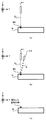
- FIGS. 2 (a) to 2 (c) are cross-sectional views each showing light irradiation and formation material supply in a certain area on the workpiece.
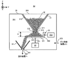
- FIG. 3 is a cross-sectional view showing the structure of the material supply device of the present embodiment.
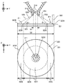
- FIG. 4 is a cross-sectional view and a plan view showing a part of the material supply device in an enlarged manner.
- FIG. 5 is a cross-sectional view showing the supply operation of the build material by the material supply device.
- FIG. 6 is a graph showing the relationship between the amplitude of vibration of the holding member and the supply amount of the forming material.
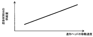
- FIG. 7 is a graph showing the relationship between the moving speed of the forming head and the supply amount of the forming material.
- FIG. 8 is a cross-sectional view showing the structure of the material supply device of the first modification.
- FIG. 9 is a cross-sectional view showing a structure of a material supply device of a second modified example.
- FIG. 10 is a cross-sectional view showing the structure of the material supply device of the third modification.
- FIG. 11 is a cross-sectional view showing the structure of the material supply device of the fourth modification.
- FIG. 12 is a cross-sectional view showing the structure of the material supply device of the fifth modification.
- FIG. 13 is a cross-sectional view showing the structure of the material supply device of the sixth modification.
- FIG. 14 is a cross-sectional view showing a structure of a material supply device of a seventh modified example.
- FIG. 15 is a cross-sectional view showing the structure of the material supply device of the eighth modification.
- each of the X-axis direction and the Y-axis direction is a horizontal direction (that is, a predetermined direction in a horizontal plane), and the Z-axis direction is a vertical direction (that is, a direction orthogonal to the horizontal plane). In the vertical direction).
- the rotational directions (in other words, the inclined directions) around the X axis, the Y axis and the Z axis are referred to as the ⁇ X direction, the ⁇ Y direction and the ⁇ Z direction, respectively.
- FIG. 1 is a cross-sectional view showing an example of the structure of a modeling system 1 of the present embodiment.
- the shaping system 1 can form a shaped object (specifically, a three-dimensional object).
- the shaping system 1 can form a shaped object on a work W as a basis for forming an object.
- the shaping system 1 can form a shaped object by performing additional processing on the workpiece W.
- the modeling system 1 can form a modeled object on the stage 43.
- the shaping system 1 can form a shaped object on the existing structure.
- the shaping system 1 may form a shaped object integrated with the existing structure.
- the operation of forming a shaped object integrated with an existing structure is equivalent to the operation of adding a new structure to the existing structure.
- the shaping system 1 may form a shaped object that can be separated from the existing structure.
- FIG. 1 shows an example in which the work W is an existing structure held by the stage 43. Also, in the following description, the description will be made using an example in which the workpiece W is an existing structure held by the stage 43.
- the shaping system 1 can form a shaped object by the laser buildup welding method. That is, it can be said that the modeling system 1 is a 3D printer that forms an object using the layered modeling technology.
- the additive manufacturing technology is also referred to as rapid prototyping, rapid manufacturing, or additive manufacturing.
- the shaping system 1 includes a material supply device 3, a shaping device 4, a light source 5, a gas supply device 6, and a control device 7, as shown in FIG.
- the material supply device 3, the modeling device 4, the light source 5, the gas supply device 6, and the control device 7 are housed in a housing C.
- the modeling apparatus 4 is accommodated in the upper space UC of the housing C, and the housing in which the material supply device 3, the light source 5, the gas supply device 6 and the control device 7 are located below the upper space UC. It is accommodated in the lower space LC of the body C.
- the arrangement positions of the material supply device 3, the modeling device 4, the light source 5, the gas supply device 6 and the control device 7 in the housing C are not limited to the arrangement positions shown in FIG. 1.
- the material supply device 3 supplies the modeling material M to the modeling device 4.
- the material supply device 3 is a desired supply according to the necessary amount so that the modeling material M is supplied to the modeling device 4 in an amount required for the modeling device 4 to form a modeled object per unit time.
- Supply molding material M at a rate. That is, the material supply device 3 supplies the modeling material M such that the supply amount of the modeling material M per unit time becomes the supply amount corresponding to the desired supply rate.
- the modeling material M is a material that can be melted by irradiation with light EL having a predetermined intensity or more.
- a modeling material M for example, at least one of a metallic material and a resinous material can be used.
- the shaping material M other materials different from metallic materials and resinous materials may be used.
- the shaping material M is a powdery or granular material. That is, the modeling material M is a granular material.
- the shaping device 4 processes the shaping material M supplied from the material supply device 3 to form a shaped object.
- the modeling apparatus 4 includes a modeling head 41, a drive system 42, and a stage 43.
- the forming head 41 includes an irradiation system 411 and a material nozzle (that is, a supply system that supplies the forming material M) 412.
- the modeling head 41, the drive system 42, and the stage 43 are accommodated in the chamber 44.
- the irradiation system 411 emits the light EL from the emission unit 411a. Specifically, the irradiation system 411 is optically connected to the light source 5 that emits the light EL via a light guide path (not shown) such as an optical fiber. The irradiation system 411 emits the light EL propagating from the light source 5 through the light guide path. The irradiation system 411 irradiates the light EL from the irradiation system 411 downward (that is, on the ⁇ Z side). Below the irradiation system 411, a stage 43 is disposed. When the work W is mounted on the stage 43, the irradiation system 411 irradiates the light EL toward the work W.
- the irradiation system 411 irradiates the workpiece W with the light EL. Furthermore, under the control of the control device 7, the state of the irradiation system 411 can be switched between the state in which the light EL is irradiated and the state in which the light EL is not irradiated.
- the material nozzle 412 has a supply outlet 412a for supplying the build material M.
- the material nozzle 412 supplies the build material M from the supply outlet 412.
- the material nozzle 412 is physically connected to the material supply device 3 which is a supply source of the forming material M via a pipe (not shown) or the like.
- the material nozzle 412 supplies the build material M supplied from the material supply device 3 at a desired supply rate via a pipe.
- the material nozzle 412 is drawn in a tube shape in FIG. 1, the shape of the material nozzle 412 is not limited to this shape.
- the material nozzle 412 supplies the build material M downward (ie, on the ⁇ Z side) from the material nozzle 412. Below the material nozzle 412, a stage 43 is disposed.
- the material nozzle 412 supplies the forming material M toward the workpiece W.
- the material nozzle 412 is aligned with the irradiation system 411 so as to supply the modeling material M toward the area (or the vicinity thereof) where the irradiation system 411 irradiates the light EL.
- the drive system 42 moves the shaping head 41.
- the drive system 42 moves the modeling head 41 along each of the X axis, the Y axis, and the Z axis.
- the drive system 42 may be moved along at least one of the ⁇ X direction, the ⁇ Y direction, and the ⁇ Z direction, in addition to each of the X axis, the Y axis, and the Z axis.
- the drive system 42 includes, for example, a motor.
- region where the modeling material M is supplied may be controllable separately.
- At least a part of the position of the ejection unit 411a, the orientation of the ejection unit 411a, the position of the supply outlet 412a, and the orientation of the supply outlet 412a may be adjustable. Further, the position of the area to be irradiated with the light EL may be adjusted by moving the optical member of the irradiation system 411.
- the stage 43 can hold the work W. Furthermore, the stage 43 can release the held work W.
- the irradiation system 411 described above irradiates the light EL in at least a part of a period in which the stage 43 holds the work W.
- the material nozzle 412 described above supplies the build material M in at least a part of a period in which the stage 43 holds the workpiece W.
- a part of the modeling material M supplied by the material nozzle 412 may scatter or spill out from the surface of the workpiece W to the outside of the workpiece W (for example, to the periphery of the stage 43).
- the shaping system 1 may be provided with a recovery device for recovering the scattered or spilled build material M around the stage 43.
- the light source 5 emits, for example, at least one of infrared light, visible light and ultraviolet light as light EL. However, other types of light may be used as the light EL.
- the light EL is a laser light.
- the light source 5 includes a laser light source (for example, a laser diode (LD: Laser Diode).
- LD Laser Diode
- the light EL may not be a laser light, and the light source 5 may be any light source (for example, LED (Light Emitting)). It may include a diode), a discharge lamp etc.).
- the gas supply device 6 is a supply source of an inert gas. Nitrogen gas or argon gas is mentioned as an example of inert gas.
- the gas supply device 6 supplies an inert gas into the chamber 44 of the modeling device 4. As a result, the internal space of the chamber 44 becomes a space purged with an inert gas.
- the gas supply device 6 further supplies an inert gas to the material supply device 3 as well.
- the inert gas supplied to the material supply device 3 is mainly used to pump the building material M, as described later. Therefore, the gas supply device 6 supplies the pressurized inert gas to the material supply device 3. Note that the gas supply to the chamber 44 and the gas supply to the material supply device 3 may be separately controlled.
- the gas supply amount per unit time to the chamber 44 and the gas supply amount per unit time to the material supply device 3 may be different.
- the gas supply to one of the chamber 44 and the material supply device 3 may be performed while the gas supply to the other is stopped.
- characteristics for example, temperature and the like
- the composition of the gas supplied to the chamber 44 and the gas supplied to the material supply device 3 may be different.
- the gas supply apparatus that supplies the gas to the chamber 44 and the gas supply apparatus that supplies the gas to the material supply apparatus 3 may be different.
- the control device 7 controls the operation of the modeling system 1.
- the control device 7 may include, for example, a central processing unit (CPU) and a memory.
- the control device 7 controls the emission mode of the light EL by the irradiation system 411.
- the emission mode includes, but is not limited to, at least one of the intensity of the light EL and the emission timing of the light EL.
- the emission mode may include at least one of the emission time of the pulsed light and the ratio (duty) of the emission time of the pulsed light to the extinction time when the light EL is pulsed light.
- the control device 7 controls the movement mode of the modeling head 41 by the drive system 42.
- the movement mode includes, but is not limited to, at least one of movement amount, movement speed, movement direction, and movement timing.
- the control device 7 controls the supply mode of the build material M by the material supply device 3. Delivery modes include, but are not limited to, delivery rates.
- the shaping system 1 forms a shaped object on the work W based on three-dimensional model data (for example, CAD (Computer Aided Design) data) of a shaped object to be formed.
- three-dimensional model data for example, measurement data of CT (Computed Tomography) and MRI (Magnetic resonance imaging) may be used.
- the modeling system 1 sequentially forms, for example, a plurality of layered partial structures (hereinafter, referred to as “structural layers”) aligned in the Z-axis direction in order to form a modeled object.
- the modeling system 1 sequentially forms a plurality of structural layers obtained by rounding the modeled object along the Z-axis direction.
- a three-dimensional object which is an assembly of a plurality of structural layers is formed.
- movement which forms a molded article by forming several structural layers one by one in order is demonstrated.
- the shaping system 1 controls the control unit 7 so as to eject a portion 411a of the irradiation system 411 with respect to a desired area on the workpiece W (specifically, an area where a structure for forming a certain structural layer is to be formed). Emits light EL.
- the condensing position of the light EL substantially coincides with the surface of the workpiece W.
- the molten pool that is, the pool of the metal melted by the light EL
- MA is formed on the work W by the light EL emitted from the emitting portion 411a of the irradiation system 411. .
- the shaping system 1 supplies the shaping material M from the material nozzle 412 to the molten pool MA as shown in FIG. 2 (b) under the control of the control device 7. As a result, the shaping material M supplied to the molten pool MA is melted. When the molten pool MA is not irradiated with the light EL with the movement of the shaping head 41, the modeling material M melted in the molten pool MA is cooled and solidified again (that is, solidified). As a result, as shown in FIG. 2 (c), the resolidified shaping material M is deposited on the work W. That is, a three-dimensional structure is formed by the deposit of the resolidified shaping material M.
- the formation of the molten pool MA by the light irradiation EL, the supply of the forming material M, the melting, and the resolidification thereof are repeated while moving the forming head 41 relative to the work W along the XY plane.
- the light EL is selectively irradiated to a region on the work W where it is desired to form a structure, while it is not selectively irradiated to the region on the work W where it is not desirable to form a structure.
- a structural layer corresponding to an aggregate of the solidified modeling material M is formed.
- the modeling system 1 performs an operation for forming such a structural layer under three-dimensional model data (in particular, three-dimensional model data corresponding to the first structural layer # 1) under the control of the control device 7. Do based on. As a result, the first structure layer # 1 is formed on the work W. Thereafter, the modeling system 1 forms a second structural layer # 2 on the workpiece W.
- the control device 7 first controls the drive system 42 so that the shaping head 41 moves along the Z-axis direction. Specifically, the control device 7 controls the drive system 42 so that the area to which the light EL is irradiated and the area to which the modeling material M is supplied are set on the surface of the first structural layer # 1. The molding head 41 is moved toward the + Z axis side.
- the condensing position of light EL substantially coincides with the surface of the structural layer # 1.
- the modeling system 1 performs an operation similar to the operation of forming the first structural layer # 1 under the control of the control device 7, based on the three-dimensional model data corresponding to the second structural layer # 2.
- the second structural layer # 2 is formed on the first structural layer # 1.
- the same operation is repeated until all structural layers constituting the object to be formed on the work W are formed.
- a three-dimensional object is formed by the assembly of the plurality of structural layers.
- the position of the shaping head 41 is changed in the Z-axis direction so that the light condensing position of the light EL substantially coincides with the lower structural layer (or the surface of the work W). It is also good.
- the condensing position of the light EL may be changed by, for example, the movement of the optical member of the irradiation system 411 without moving the modeling head 41.
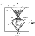
- FIG. 3 is a cross-sectional view showing the structure of the material supply device 3.
- FIG. 4 is a cross-sectional view and a plan view showing a part of the material supply device 3 in an enlarged manner.
- the material supply device 3 includes a hopper 31, a holding member 32, a vibrating device 33, and a material delivery member 34.
- the hopper 31, the holding member 32, the vibrating device 33, and the material delivery member 34 are accommodated in the internal space 351 of the housing 35. Note that at least a part of the vibration device 33 may be disposed outside the housing 35.
- the hopper 31 is a device for storing the modeling material M.
- the hopper 31 has a funnel-like shape (that is, an inverted conical shape).
- a space surrounded by a partition having a funnel-like shape corresponds to the storage space 313 for storing the shaping material M.
- the hopper 31 may have another shape.
- the shape of the hopper 31 may be another shape (for example, a shape of an inverted quadrangular pyramid).
- a supply port 311 is formed at the lower end of the hopper 31 (that is, below the storage space 313).
- the supply port 311 is an opening (that is, a through hole) which penetrates the partition wall at the bottom of the hopper 31 along the Z-axis direction.
- the supply port 311 is defined by (i.e. surrounded by) the lower inner surface 314 of the hopper 31.
- the shape of the cross section of the supply port 311 (specifically, the cross section along the XY plane) is circular, but may be another shape. Other shapes include at least one of an oval, an oval and a rectangle.
- the supply port 311 is an opening for supplying the modeling material M from the hopper 31 to the lower side of the hopper 31 (that is, to the ⁇ Z side). That is, the modeling material M stored in the hopper 31 is supplied to the outside of the hopper 31 through the supply port 311 (in other words, discharged or dropped).
- An air vent 312 is formed at the top of the hopper 31.
- the storage space 313 of the hopper 31 in particular, the space above the molding material M stored in the storage space 313) and the internal space 351 of the housing 35 (in particular, the modeling material M is discharged from the hopper 31 Through the partition wall of the hopper 31 so as to connect the By forming the vent holes 312, even when the building material M is stored in the storage space 313, an imbalance between the pressure in the storage space 313 and the pressure in the internal space 351 is prevented, and from the hopper 31.
- the molding material M is supplied smoothly. As a result, the modeling material M is not suddenly supplied from the hopper 31 due to the imbalance between the pressure of the storage space 313 and the pressure of the internal space 351.
- the modeling material M is not smoothly supplied from the hopper 31 (or the modeling material M discharged from the hopper 31 has the supply port 311 It does not flow back to the storage space 313 of the hopper 31).
- the storage space 313 of the hopper 31 and the internal space 351 of the housing 35 are connected by a pipe or the like so as to eliminate the imbalance between the pressure of the storage space 313 and the pressure of the internal space 351 instead of forming the vent holes 312. You may Further, for example, when the pressure difference between the storage space 313 and the internal space 351 is small, the storage space 313 and the internal space 351 may not be connected via the vent hole 312 or the like.
- the holding member 32 holds the modeling material M supplied from the supply port 311 of the hopper 31 to the outside of the hopper 31.
- the holding member 32 is disposed below the hopper 31.
- the holding member 32 is disposed below the supply port 311.
- the holding member 32 is disposed such that a portion of the holding member 32 is located directly below the supply port 311. That is, the holding member 32 is disposed such that a part of the holding member 32 faces the supply port 311 along the Z-axis direction.
- the holding member 32 includes a bottom member 321 and a side wall member 322.
- the bottom member 321 is disposed below the hopper 31.
- the bottom member 321 is disposed below the supply port 311.
- the bottom member 321 is disposed such that a portion of the bottom member 321 is located directly below the supply port 311. That is, the bottom member 321 is disposed such that a portion of the bottom member 321 faces the supply port 311 along the Z-axis direction.
- the upper surface (that is, the surface on the + Z side) of the bottom member 321 serves as a holding surface 323 for holding the modeling material M supplied from the supply port 311.
- the holding surface 323 is disposed below the hopper 31.
- the holding surface 323 is disposed below the supply port 311.
- the holding surface 323 is disposed such that a portion of the holding surface 323 is located directly below the supply port 311. That is, the holding surface 323 is arranged such that a part of the holding surface 323 faces the supply port 311 along the Z-axis direction.
- the holding surface 323 is a plane along the XY plane (or parallel to the XY plane), and is a horizontal plane.
- the holding surface 323 is disposed at a position separated from the supply port 311 in the Z-axis direction.
- the holding surface 323 does not contact the lower end portion 3141 of the lower inner surface 314 of the hopper 31 that defines the supply port 311.
- the holding surface 323 does not contact the lower surface 315 of the hopper 31.
- the holding surface 323 does not block the supply port 311.
- the lower surface 315 of the hopper 31 may or may not be parallel to a surface (or a horizontal surface) along the XY plane.
- the size of the holding surface 323 is a size that satisfies the first condition, the second condition, and the third condition described below.
- the first condition is that the size of the holding surface 323 is larger than the cross section of the supply port 311.
- the cross section of the supply port 311 can be a cross section in a plane parallel to the holding surface 323. That is, the first condition is a condition that the area S2 of the holding surface 323 becomes larger than the cross-sectional area S1 of the supply port 311, as shown in FIG.
- the second condition extends outward from the lower end portion 3141 of the lower inner surface 314 of the hopper 31 defining the supply port 311 and enlarges the holding surface 323 (or the holding surface 323).
- the virtual surface VS2 which is a surface to be the repose angle ⁇ r of the modeling material M is described by the virtual surface VS2).
- the second condition is that the outer edge (that is, the circumference) is defined by the intersection 3230 of the holding surface 323 and the virtual surface VS2 and the holding surface 323 (or a virtual surface obtained by enlarging the holding surface 323).
- the condition is that the size of the circular area 3231 which is at the same height as the holding surface 323 is equal to or larger than the size.
- the second condition is that the holding surface 323 is large enough to include the area 3231 (that is, the area 3231 can be set on the holding surface 323). That is, the virtual surface VS2 extends from the lower end portion 3141 to the holding surface 323, and is a surface inclined with respect to the holding surface 323 such that the angle formed with the holding surface 323 is the repose angle ⁇ r of the modeling material M. It is.
- the area 3231 is substantially a circular area extending outward from the reference point 3233 (see FIG. 4) on the holding surface 323 located directly below the supply port 311 and larger than the cross section of the supply port 311. It can be said that there is.
- the repose angle ⁇ r can maintain the stability of the mountain of the modeling material M deposited on the holding surface 323 under the situation where the holding member 32 is at rest (that is, the spontaneous movement of the mountain of the modeling material M) (Does not cause a serious collapse)) is the maximum angle of the slope of the mountain. Therefore, the second condition can substantially maintain the repose angle ⁇ r of the mountain of the modeling material M deposited on the holding surface 323 under the situation where the holding member 32 is at rest (that is, the modeling material It can also be said that the condition is that the holding surface 323 becomes large to the extent that the angle of the slope of the mountain of M can be made equal to or less than the repose angle ⁇ r.
- the radius of the circular area 3231 is larger than the distance between the supply port 311 and the holding surface 323.
- the area 3231 may not be a circular area.
- a circle inscribed in the area or a circumscribed circle may be regarded as the area 3231.
- the third condition is that the holding surface 323 is large enough that the holding surface 323 can be provided with a region 3232 (see FIG. 4) extending outside the region 3231 in addition to the region 3231. That is, the third condition is that the holding surface 323 is large enough to set the area 3232 outside the area 3231.
- the holding surface 323 includes the area 3232, as is apparent from FIG. 4, the lower end portion of the hopper 31 (that is, the edge of the supply port 311) 3141 to the outer edge 3234 of the holding surface 323 (that is, the area 3232).
- An angle ⁇ 1 formed by the virtual surface VS1 which is an outer edge and is a surface extending to the end of the holding surface 323 with the holding surface 323 is equal to or less than the repose angle ⁇ r.
- the holding surface 323 can hold the modeling material M between the virtual surface VS1 and the supply port 311. Since the first condition in which the holding surface 323 is larger than the cross section of the supply port 311 is satisfied, the virtual surface VS1 is a surface inclined with respect to the holding surface 323. Furthermore, when the holding surface 323 includes the region 3232, the virtual surface VS2 is a surface that intersects the holding surface 323.
- the side wall member 322 is a member (in other words, a portion) protruding from the bottom member 321 to the + Z side. In the example shown in FIGS. 3 and 4, the side wall member 322 is formed at the outer edge 3234 (or in the vicinity thereof) of the holding surface 323.
- the sidewall member 322 is a stopper for preventing the modeling material M from spilling out (i.e., falling, hereinafter the same) from the holding surface 323 (i.e., the bottom member 321) to an unintended region outside the holding surface 323. Act as.
- the side wall member 322 guides the shaping material M on the holding surface 323 so that the modeling material M spills from the holding surface 323 (that is, the bottom member 321) to the intended area outside the holding surface 323. Function as a guide member.
- the area intended as the area where the build material M falls off is the area where the material delivery member 34 is located from the holding surface 323.
- the modeling material M held by the holding surface 323 falls from the holding surface 323 and is carried out to the material delivery member 34. For this reason, while the modeling material M is carried out from the holding surface 323 to the material delivery member 34, the side wall member 322 prevents the modeling material M from falling off from the holding surface 323 to the portion where the material delivery member 34 is not located.
- the side wall member 322 is formed in an area on the holding surface 323 (in particular, the area at or near the outer edge 3234) where the build material M should not spill out.
- the side wall member 322 is not formed in the area on the holding surface 323 (in particular, the area at or near the outer edge 3234) where the build material M is to be dropped.
- the side wall member 322 may be provided on the + X side and the ⁇ X side of the outer edge 3234 of the holding surface 323.
- at least a part of the side wall member 322 may be provided in the region 3231 on the holding surface 323.
- the vibration device 33 vibrates the holding member 32 under the control of the control device 7. Specifically, the vibration device 33 is connected to the holding member 32 (the bottom member 321 in the example shown in FIG. 3) via the vibration transmission member 331. The vibration device 33 transmits the vibration to the holding member 32 via the vibration transmission member 331. As a result, the holding member 32 vibrates.
- the vibrating device 33 may vibrate the holding member 32 along the X-axis direction, may vibrate the holding member 32 along the Y-axis direction, and vibrate the holding member 32 along the Z-axis direction. It may be made to vibrate, and it may be made to vibrate in the direction which intersects at least one of X axis, Y axis, and Z axis.
- the vibration device 33 includes, but is not limited to, an ultrasonic motor or an electromagnetic motor, and an actuator using a laminated piezoelectric element.
- the holding member 32 may be vibrated indirectly using remote force such as electromagnetic force or resonance without using the vibration transfer member 331.
- the vibration by the vibration device 33 is not limited to the periodic vibration, and may be a non-periodic vibration.
- the vibrating device 33 vibrates the holding member 32 under the control of the control device 7 to hold a part of the modeling material M held by the holding surface 323 through the outer edge 3234 of the holding surface 323. Fall outside of the That is, the vibrating device 33 vibrates the holding member 32 to hold a part of the modeling material M held by the holding surface 323 (that is, deposited on the holding surface 323) from the holding surface 323.
- the surface 323 is carried out to the outside of the holding surface 323 (specifically, the material delivery member 34).
- the vibration device 33 under the control of the control device 7, in the vibration device 33, a part of the modeling material M held by the holding surface 323 is transmitted from the holding surface 323 to the holding surface 323 and outside the holding surface 323 (specifically The holding member 32 is vibrated so as to be carried out to the material delivery member 34).
- the holding surface 323 and the supply port 311 of the hopper 31 are separated (that is, not in contact with each other). That is, the holding member 32 and the hopper 31 are separated (that is, not in contact with each other). For this reason, the vibration device 33 does not vibrate the hopper 31.
- the material delivery member 34 receives the modeling material M carried out of the holding surface 323 (that is, dropped, and so forth).
- the material delivery member 34 is disposed at a position where it can receive the modeling material M carried out of the holding surface 323 in order to receive the modeling material M carried out of the holding surface 323.
- the material delivery member 34 is located at least one of the lower side and the diagonal lower side of the holding surface 323.
- the modeling material M is carried out of the holding surface 323 so as to spill out (that is, fall) from the holding surface 323, and the material delivery member 34 is in the dropping path of the modeling material M from the holding surface 323. Be placed.
- the material delivery member 34 has a funnel-like shape (for example, an inverted conical shape) in order to properly receive the build material M carried out of the holding surface 323.
- the material delivery member 34 receives the collection of the build material M carried out of the holding surface 323 by a partition having a funnel-like shape.
- the material delivery member 34 may have another shape (e.g., an inverted quadrangular pyramid shape).
- the material delivery member 34 further delivers the modeling material M received from the holding surface 323 to the outside of the material supply device 3 (that is, to the modeling device 4).
- a delivery port 341 is formed at the lower end of the material delivery member 34 in order to deliver the modeling material M to the modeling apparatus 4.
- the delivery port 341 is an opening (i.e., a through hole) penetrating the partition wall at the bottom of the material delivery member 34 along the Z-axis direction.
- the shape of the cross section of the delivery port 341 (specifically, the cross section along the XY plane) is circular, but may be another shape. Other shapes include at least one of an oval, an oval and a rectangle.
- the housing 35 is formed with a delivery port 352.
- the delivery port 352 is in communication with the delivery port 341 of the material delivery member 34.
- the above-mentioned unshown pipe connected to the modeling device 4 is connected to the delivery port 352. Accordingly, the modeling material M delivered by the material delivery member 34 is delivered to the modeling apparatus 4 via the delivery ports 341 and 352 and a pipe (not shown).
- An inlet 353 is further formed in the housing 35.
- the inlet (air supply port) 353 is connected to the gas supply device 6 described above. Therefore, pressurized inert gas is supplied to the internal space 351 of the housing 35 from the gas supply device 6 described above via the inlet 353.
- a material replenishment port 354 is further formed in the housing 35.
- the material replenishment port 354 is an opening for replenishing the hopper 31 with the modeling material M.
- the material replenishment port 354 is normally sealed by a lid (not shown) (specifically, during a period when the hopper 31 is not replenished with the build material M). For this reason, the state of the internal space 351 is normally maintained in the pressurized state.
- the lid of the material replenishment port 354 is opened during the time of replenishing the hopper 31 with the build material M.
- the material replenishment port 354 may be used for purposes other than replenishment of the modeling material M (for example, replacement of parts disposed in the housing 35, maintenance, etc.).
- the holding surface 323 is a surface along the XY plane, and is separated from the supply port 311 (in other words, the lower surface 315 of the hopper 31) along the Z-axis direction. It is placed below. For this reason, as shown in FIG. 5, the modeling material M supplied (that is, dropped) from the supply port 311 is deposited on the holding surface 323.
- the holding surface 323 holds the modeling material M such that the modeling material M supplied from the supply port 311 is deposited on the holding surface 323.
- the holding surface 323 holds the modeling material M such that the modeling material M is held between the supply port 311 and the holding surface 323 (that is, between the lower surface 315 of the hopper 31 and the holding surface 323).
- the holding surface 323 holds the amount of the modeling material M according to the distance D between the supply port 311 and the holding surface 323. Specifically, the holding surface 323 holds a large amount of the modeling material M as the distance D between the supply port 311 and the holding surface 323 increases. That is, the amount of the modeling material M held by the holding surface 323 increases as the distance D between the supply port 311 and the holding surface 323 increases.
- the size of the holding surface 323 is a size that satisfies the first condition that the holding surface 323 becomes larger than the cross section of the supply port 311. For this reason, as shown in FIG. 5, the modeling material M supplied from the supply port 311 is deposited on the holding surface 323 so as to form a mountain of the modeling material M spreading outward from the supply port 311 downward. Be done.
- the holding surface 323 holds more modeling material M the closer to the reference point 3233 (see FIG. 4) on the holding surface 323 located directly below the supply port 311.
- the holding surface 323 holds the modeling material M such that the modeling material M is held between the supply port 311, the holding surface 323, and the virtual surface VS1 (see FIG. 4) to form a mountain of the modeling material M.
- the size of the holding surface 323 is such that the circular area 3231 can be set on the holding surface 323 (that is, deposited on the holding surface 323 in a situation where the holding member 32 stands still) To the extent that it is possible to maintain the mountain repose angle ⁇ r of the modeling material M), and the size that satisfies the second condition that the holding surface 323 becomes large.
- the holding surface 323 is a holding surface in a state where the angle between the slope of the molding material M supplied from the supply port 311 and the holding surface 323 does not exceed the repose angle ⁇ r.
- the shaping material M can be held as formed on H.323. That is, the holding surface 323 is a molding material so that the pile of the molding material M does not spontaneously collapse under the condition that the holding member 32 is stationary (that is, the vibration device 33 does not vibrate the holding member 32). M can hold.
- the size of the holding surface 323 is the third condition that the holding surface 323 is large enough to include the region 3232 which spreads outside the region 3231 in addition to the region 3231. Meet. Therefore, the holding surface 323 can hold the modeling material M using not only the region 3231 but also the region 3232. For this reason, the holding surface 323 can hold a mountain formed by the modeling material M on the holding surface 323 in a state where an angle formed by the inclined surface and the holding surface 323 is equal to or less than the repose angle ⁇ r. As a result, the holding surface 323 can hold the modeling material M such that the peaks of the modeling material M supplied from the supply port 311 become more unlikely to collapse spontaneously.
- the modeling material M supplied from the hopper 31 to the outside of the hopper 31 is temporarily held by the holding surface 323 in a stable manner.
- the modeling material M deposited on the holding surface 323 is in contact with the supply port 311, and in the situation where the holding member 32 is at rest, the deposited modeling material M blocks the supply port 311 and further modeling material M Is prevented from being supplied to the holding surface 323.
- the holding member 32 is vibrated by the vibration device 33.
- the stationary holding member 32 starts to vibrate, a part of the modeling material M constituting the mountain gradually begins to collapse from the mountain of the modeling material M which is stably held by the holding surface 323.
- a part of the modeling material M constituting the mountain gradually starts to separate from the mountain of the modeling material M which the holding surface 323 is stably held. .
- a part of the modeling material M constituting the mountain is a unit from the mountain of the modeling material M which the holding surface 323 has stably held. It will continue to collapse gradually by a fixed amount every hour.
- a part of the modeling material M constituting the mountain is for every unit time
- the building material M which has fallen or separated from the mountain falls from the holding surface 323 to the outside of the holding surface 323 (that is, the material delivery member 34).
- a fixed amount of the modeling material M is carried out to the material carry-out device 34 every unit time.
- the vibration device 33 stops, the modeling material M deposited on the holding surface 323 stops collapsing, and the modeling material M does not spill out of the holding surface 323. That is, the carrying out of the modeling material M from the holding surface 323 to the material delivery member 34 is stopped. As a result, the supply of the modeling material M from the material supply device 3 to the modeling device 4 is also stopped. Therefore, the vibration device 33 does not have to supply the modeling material M to the modeling device 4 under the control of the control device 7 (for example, at the timing when the material nozzle 412 does not have to supply the modeling material M). , Stop the vibration of the holding member 32.
- the amount of the modeling material M carried out from the holding surface 323 to the outside of the holding surface 323 per unit time (that is, the carried-out amount of the modeling material M per unit time) can be controlled in the state of vibration of the holding member 32 is there. For this reason, in the vibration device 33, the amount of the modeling material M carried out from the holding surface 323 to the material delivery member 34 per unit time under the control of the control device 7 is that of the modeling material M necessary for forming a modeling object.
- the vibration state of the holding member 32 is set so as to achieve a desired carry-out amount corresponding to the supply rate.
- the vibrating device 33 is under the control of the control device 7 while the shaping device 4 forms a shaped object (more specifically, while the material nozzle 412 continues to supply the shaping material M)
- the holding member 32 is vibrated such that the holding member 32 continues to vibrate in the set vibration state.
- a fixed amount of the modeling material M required per unit time for the modeling apparatus 4 to form a modeled object is carried out.
- the state of vibration may include, for example, the amplitude (ie intensity) of the vibration.
- the amplitude of the vibration increases, the holding surface 323 vibrates more. For this reason, the amount of the modeling material M which falls or separates per unit time from the peak of the modeling material M which the holding surface 323 was holding increases, so that the amplitude of a vibration becomes large. That is, as the amplitude of the vibration increases, the amount of the modeling material M carried out from the holding surface 323 to the outside of the holding surface 323 increases per unit time.
- the quantity of the modeling material M carried out from the holding surface 323 to the outside of the holding surface 323 per unit time increases, the quantity of modeling material M supplied from the material supply device 3 to the modeling apparatus 4 per unit time In other words, the supply amount is increased. Therefore, as shown in FIG. 6, as the amplitude of the vibration increases, the amount of supply of the modeling material M supplied from the material supply device 3 to the modeling device 4 per unit time increases.
- the control device 7 is carried out from the holding surface 323 to the material delivery member 34 per unit time, taking into consideration the relationship between the amplitude of the vibration of the holding member 32 and the supply amount of the modeling material M.
- the amplitude of the vibration of the holding member 32 is set so that the amount of the modeling material M becomes a desired carry-out amount corresponding to the supply rate of the modeling material M necessary for forming the three-dimensional object.
- the control device 7 holds the holding member 32.
- the amplitude of the vibration of is set to A1.
- the controller 7 sets the amplitude of the vibration of the holding member 32 to A2 (where A2 ⁇ A1).
- the control device 7 may set the amplitude of vibration so as to satisfy the constraint that the peaks of the modeling material M held by the holding surface 323 gradually collapse (that is, not collapse at once).
- the state of vibration may include, for example, the frequency of vibration.
- the holding surface 323 vibrates at a higher speed. For this reason, as the frequency of vibration increases, the amount of the modeling material M that falls or separates per unit time from the peak of the modeling material M held by the holding surface 323 increases. That is, as the frequency of vibration increases, the amount of the modeling material M carried out from the holding surface 323 to the outside of the holding surface 323 per unit time increases. Therefore, like the amplitude of the vibration, the amount (the amount of supply) of the modeling material M supplied from the material supply device 3 to the modeling device 4 per unit time increases as the frequency of the vibration increases.
- the control device 7 is carried out from the holding surface 323 to the material delivery member 34 per unit time in consideration of the relationship between the frequency of the vibration of the holding member 32 and the supply amount of the modeling material M.
- the frequency of vibration of the holding member 32 may be set such that the amount of the modeling material M is a desired carry-out amount corresponding to the supply rate of the modeling material M necessary for forming the three-dimensional object.
- the control device 7 may set the frequency of vibration so as to satisfy the constraint that the peaks of the modeling material M held by the holding surface 323 gradually collapse (that is, not collapse at once).
- the amount of the modeling material M in the first state to be carried out from the holding surface 323 per unit time and the unit surface 31 to be carried out per unit time There is a possibility that the amount of the modeling material M in the second state (but the second state is different from the first state) may not be the same. That is, the amount of the modeling material M in the first state carried out per unit time from the holding surface 323 vibrating in a certain state, and the second different one carried out per unit time from the holding surface 323 vibrating in the same state. The amount of the modeling material M in the state may not be the same.
- the amount of the forming material M of the second type (but the second type is different from the first type) may not be the same.
- the amount of the modeling material M having the first particle size carried out per unit time from the holding surface 323 vibrating in a certain state, and the second carried out per unit time from the holding surface 323 vibrating in the same state may not be the same.
- the amount of the modeling material M of the first shape (in particular, the outer shape) carried out per unit time from the holding surface 323 vibrating in a certain state.
- the amount of the modeling material M in the second shape (but the second shape is different from the first shape) may not be the same.
- the amount of the modeling material M having a second value (where the second value is different from the first value) of the friction coefficient of the surface may not be the same.
- the control device 7 relates the relationship between the state of the modeling material M and the supply volume of the modeling material M
- the amount of the molding material M carried out from the holding surface 323 to the material delivery member 34 per unit time is the desired carry-out amount according to the supply rate of the molding material M necessary for forming the
- the state of vibration of the holding member 32 may be set so that
- the state of the modeling material M includes at least one of the type of the modeling material M, the size (particle diameter) of the modeling material M, the shape of the modeling material M, and the friction coefficient of the surface of the modeling material M It is also good.
- the holding surface 323 holds substantially the same amount of the modeling material M. In other words, the holding surface 323 holds the amount of the molding material M according to the distance D between the lower surface 315 of the hopper 31 and the holding surface 323 regardless of the unloading of the molding material M from the holding surface 323. .
- the modeling material M carried out of the holding surface 323 falls from the holding surface 323 to the material delivery member 34.
- the material delivery member 34 receives the modeling material M carried out of the holding surface 323.
- the modeling material M received by the material delivery member 34 is delivered to the outside of the material supply device 3 (that is, to the modeling device 4).
- the inert gas pressurized from the gas supply device 6 is supplied to the internal space 351 of the housing 35 in which the material delivery member 34 is accommodated, via the inflow port 353.
- the material delivery member 34 delivers the modeling material M to the modeling apparatus 4 by pressure feeding with the inert gas.
- the modeling material M received by the material delivery member 34 is delivered so as to be pushed out in the pipe via the delivery ports 341 and 352 by the pressure of the inert gas supplied to the internal space 351.
- the shaping material M delivered through the pipe is supplied from the material nozzle 412.
- the material delivery member 34 delivers the forming material M by pumping, the amount of the forming material M delivered by the material delivery member 34 per unit time is carried out from the holding surface 323 to the material delivery member 34 per unit time. It depends on the amount of the molding material M. For this reason, the material delivery member 34 can deliver a fixed amount of the modeling material M to the modeling apparatus 4 per unit time. As a result, the material supply device 3 can supply a fixed amount of the modeling material M to the modeling device 4 per unit time. That is, in the material supply device 3, the amount of the modeling material M supplied from the material supply device 3 to the modeling device 4 per unit time is constant according to the supply rate of the modeling material M required for forming the three-dimensional object. The modeling material M can be supplied to the modeling apparatus 4 so as to obtain a desired supply amount.
- the holding member 32 disposed below the hopper 31 holds a fixed amount of the modeling material M supplied from the hopper 31, and then the unit is moved by the vibration of the holding member 32.
- a fixed amount of modeling material M is carried out from the holding surface 323 to the material delivery member 34 per hour.
- the material supply device 3 can stably supply the modeling device 4 with a fixed amount of modeling material M required per unit time for the modeling device 4 to form a modeled object. That is, the material supply device 3 can supply the modeling material M while maintaining the desired supply rate.
- the amount of the modeling material M to be carried out from the holding surface 323 to the material delivery member 34 per unit time is constant. That is, while the modeling apparatus 4 forms a modeling object, the quantity of modeling material M supplied to the modeling apparatus 4 from the material supply apparatus 3 per unit time is constant. However, under the control of the control device 7, the material supply device 3 supplies the modeling material M supplied from the material supply device 3 to the modeling device 4 per unit time while the modeling device 4 is forming a modeled object. You may change the amount of Specifically, as described above, the amount of the modeling material M carried out from the holding surface 323 to the material delivery member 34 per unit time depends on the state of vibration of the holding member 323.
- control device 7 may control the vibration device 33 so as to change the vibration state of the holding member 32 while the modeling device 4 forms a modeled object.
- the control device 7 may control the vibration device 33 so as to change the vibration state of the holding member 32 while the modeling device 4 forms a modeled object.
- the control device 7 is carried out from the material supply device 3 to the modeling device 4 per unit time based on the traveling speed of the modeling head 41 (that is, information on the traveling speed of the modeling head 41).
- the amount of the molding material M is changed. Specifically, the time during which the material nozzle 412 supplies the forming material M to a certain unit area on the work W (or a certain unit area on the structural layer already formed on the work W, and the same applies hereinafter) The faster the moving speed of the head 41, the shorter it becomes.
- the faster the moving speed of the forming head 41 the smaller the amount of the forming material M supplied to the unit area.
- the control device 7 supplies the material per unit time based on the moving speed of the forming head 41 so that the amount of the forming material M supplied to each of the plurality of unit areas on the work W becomes the same. You may change the quantity of the modeling material M supplied from three. Specifically, as shown in FIG.
- the control device 7 supplies the amount of the forming material M supplied from the material supply device 3 per unit time (that is, per unit time).
- the supply amount of the build material M per unit time may be changed so that the supply amount of the build material M is increased.
- control apparatus 7 is not limited to the scene mentioned above, and based on at least one of the information on the moving speed of the modeling head 41 and the information on the irradiation of the light EL, the material supply apparatus 3 to the modeling apparatus 4 per unit time. You may change the quantity of the modeling material M carried out.
- strength of light EL, the irradiation position of light EL, the irradiation timing of light EL, etc. are mention
- the control device 7 may change the amount of the modeling material M carried out from the material supply device 3 to the modeling device 4 per unit time in accordance with the change in the intensity of the light EL.
- the control device 7 may change the amount of the modeling material M carried out from the material supply device 3 to the modeling device 4 per unit time in accordance with the change in the irradiation timing of the light EL.
- control unit 7 controls the holding surface 323 so that the amount of the modeling material M supplied from the material supply device 3 increases per unit time as the moving speed of the modeling head 41 increases. I changed the state of vibration. However, from the upper limit of the amplitude or frequency at which the vibration device 33 can vibrate the holding surface 323, the supply amount of the modeling material M per unit time that can be supplied to the modeling device 4 is calculated back based on the supply amount. The upper limit of the moving speed of the forming head 41 in the device 4 may be set.
- the molding system 1a according to the first modification differs from the above-described molding system 1 in that the material supply apparatus 3 is replaced with a material supply apparatus 3a.
- Other configurations of the modeling system 1 a may be the same as other configurations of the modeling system 1. Therefore, the material supply device 3a of the first modification will be described below with reference to FIG.
- the material supply device 3 a differs from the above-described material supply device 3 in that the conveyance member 36 a is further provided in the internal space 351 of the housing 35.
- the other configuration of the material supply device 3 a may be the same as the other configuration of the material supply device 3.
- the transport member 36 a receives the modeling material M carried out of the holding surface 323. Further, the transport member 36 a carries out the modeling material M received from the holding surface 323 to the material delivery member 34. Therefore, in the first modification, the modeling material M is supplied from the hopper 31 to the outside of the material supply device 3 (that is, the modeling device 4) via the holding member 32, the transport member 36a and the material delivery member 34 in this order. Be done.
- the transport member 36 a is disposed at a position capable of receiving the modeling material M unloaded from the holding surface 323 in order to receive the modeling material M unloaded (that is, dropped) from the holding surface 323.
- the transport member 36 a is located at least one of the lower side and the diagonal lower side of the holding surface 323.
- the modeling material M is carried out of the holding surface 323 so as to spill out (that is, falls) from the holding surface 323, and the transport member 36a is disposed in the falling path of the modeling material M from the holding surface 323. Be done.
- the transport member 36a receives the build material M on the top surface (that is, the surface facing the + Z side) 361a. That is, the modeling material M falls from the holding surface 323 to the upper surface 361a.
- the upper surface 361a is a surface inclined with respect to the XY plane which is a horizontal surface (that is, intersects the XY plane).
- the upper surface 361 a is a surface inclined with respect to the holding surface 323. Since the upper surface 361a is inclined, the modeling material M received by the upper surface 361a rolls off the upper surface 361a.
- a material delivery member 34 is disposed on at least one of the lower side and the lower side of the upper surface 361a.
- the material delivery member 34 is disposed on the path where the modeling material M rolls down from the upper surface 361a. For this reason, the material delivery member 34 receives the shaping material M rolling down on the upper surface 361a. That is, in the first modification, the transport member 36a causes the modeling material M received from the holding surface 323 by the upper surface 361a to fall from the upper surface 361a to the outside of the upper surface 361a (that is, And the material delivery member 34).
- Such a material supply device 3a can receive the same effects as the effects that can be obtained by the material supply device 3 described above. Furthermore, in the first modification, the modeling material M carried out from the holding surface 323 to the transport member 36a rolls off the top surface 361a due to the inclination of the top surface 361a of the transport member 36a. At this time, a frictional force from the upper surface 361a acts on the modeling material M. For this reason, the modeling material M rolls down the upper surface 361a stably at a substantially constant speed.
- the transport member 36a transfers the material delivery member 34 from the upper surface 361a per unit time rather than the fluctuation (in other words, pulsation) of the amount of the modeling material M carried out from the holding surface 323 to the transport member 36a per unit time.
- the fluctuation of the quantity of the modeling material M to be carried out can be reduced.
- the transport member 36a carries out the modeling material M so as to reduce (or suppress or cancel) the fluctuation of the amount of the modeling material M carried out from the holding surface 323 to the transportation member 36a per unit time.
- the material supply device 3a can reduce the fluctuation of the amount of the modeling material M supplied from the material supply device 3a to the modeling device 4 per unit time. Therefore, the material supply device 3 can supply the modeling material M while maintaining the desired supply rate more appropriately.
- the inclination angle of the upper surface 361a with respect to the XY plane is set to an appropriate angle that can exert an effect of reducing the fluctuation of the amount of the modeling material M carried out from the holding surface 323 to the transport member 36a per unit time. It is also good.
- An example of such an angle is an angle of 30 degrees or less (in particular, an angle of 20 degrees or less).
- the inclination angle of the upper surface 361a with respect to the XY plane may be set to an appropriate angle such that the modeling material M carried out from the holding surface 322 to the transport member 36a can properly fall over the upper surface 361a.
- the surface of the upper surface 361a may be subjected to surface processing to adjust the coefficient of friction with the modeling material M so that the modeling material M can fall properly.
- the surface processing includes at least a process of changing the coefficient of friction between the modeling material M and the surface of the upper surface 361a.
- a part of the upper surface 361 of the transport member 36a may be a surface (that is, a horizontal surface) along the XY plane. At least a portion of the upper surface 361a may be a curved surface.
- the transport member 36 a may be disposed at any position as long as the modeling material M received from the holding surface 323 can be received and the modeling material M received can be transported to the material delivery member 34.
- the material supply device 36a may include a plurality of transport members 36a.
- the modeling material M is supplied from the hopper 31 to the outside of the material supply device 3 (that is, the modeling device 4) via the holding member 32, the transport member 36a and the material delivery member 34 in this order.
- the plurality of transport members 36a are a first transport member 36a that is inclined at a first inclination angle with respect to the holding surface 323, and a second inclination angle that is different from the first inclination angle with respect to the holding surface 323 And a second transport member 36a that is inclined.
- the plurality of transport members 36 a may include at least two transport members 36 a inclined at the same inclination angle with respect to the holding surface 323.
- the molding system 1b of the second modification differs from the above-described molding system 1 in that the material supply device 3 is replaced with the material supply device 3b.
- Other configurations of the modeling system 1 b may be the same as other configurations of the modeling system 1. Therefore, below, the material supply apparatus 3b of a 2nd modification is demonstrated, referring FIG.
- the material supply device 3b differs from the material supply device 3a described above in that the vibration device 33 vibrates the transport member 36a.
- the other configuration of the material supply device 3b may be the same as the other configuration of the material supply device 3a.
- the vibrating device 33 is connected to the transport member 32 via the vibration transfer member 332 b.
- the vibration device 33 transmits the vibration to the transport member 36a via the vibration transmission member 332b.
- the transport member 36a vibrates.
- the vibrating device 33 may vibrate the transport member 36a along the X-axis direction, may vibrate the transport member 36a along the Y-axis direction, and vibrate the transport member 36a along the Z-axis direction. You may
- the transport member 36a since the transport member 36a vibrates, the modeling material M carried out from the holding surface 322 to the transport member 36a stagnates on the upper surface 361a as compared with the case where the transport member 36a does not vibrate. There is less chance of doing so. That is, in the second modification, the transport member 36a can carry out the modeling material M so that the modeling material M properly falls on the upper surface 361a.
- the vibrating device 33 for vibrating the holding member 32 vibrates the transport member 36a.
- the material supply device 3b may be separately and independently provided with a vibrating device 33b that vibrates the transport member 36a.
- the molding system 1c of the third modification differs from the above-described molding system 1 in that the material supply device 3 is replaced with the material supply device 3c.
- the other configuration of the modeling system 1 c may be the same as the other configuration of the modeling system 1. Therefore, the material supply device 3c of the third modification will be described below with reference to FIG.
- the material supply device 3c differs from the material supply device 3b described above in that the holding member 32 and the transport member 36a are integrated.
- the other configuration of the material supply device 3b may be the same as the other configuration of the material supply device 3b. Even with such a material supply device 3c, it is possible to receive the same effects as the effects that can be obtained by the material supply device 3b described above.
- a molding system 1d of the fourth modification differs from the above-described molding system 1 in that a material supply device 3d is provided instead of the material supply device 3.
- the other configurations of the modeling system 1 d may be the same as the other configurations of the modeling system 1. Therefore, the material supply device 3d of the fourth modified example will be described below with reference to FIG.
- the material supply device 3d differs from the material supply device 3 described above in that it includes a distance adjustment device 37d.
- the other configuration of the material supply device 3 d may be the same as the other configuration of the material supply device 3.
- the distance adjusting device 37 d can adjust the distance D between the supply port 311 of the hopper 31 and the holding surface 323 of the holding member 32 under the control of the control device 7. That is, under the control of the control device 7, the distance adjustment device 37d measures the distance between the lower surface 315 of the hopper 31 and the holding surface 323 (that is, the distance between the lower end 3141 of the hopper 31 and the holding surface 323) D Is adjustable.
- the distance adjusting device 37 d adjusts the distance D by moving the holding member 32 relative to the hopper 31 under the control of the control device 7.
- the distance adjustment device 37d may adjust the distance D by moving the holding member 32 along the Z axis. In this case, when the holding member 32 moves to the + Z side, the distance D decreases. On the other hand, when the holding member 32 moves to the ⁇ Z side, the distance D becomes large.
- the distance adjustment device 37d may adjust the distance D by moving the hopper 31 along the Z axis in addition to or instead of moving the holding member 32 along the Z axis. In this case, when the hopper 31 moves to the + Z side, the distance D increases.
- the distance adjustment device 37 d may include, for example, an actuator or the like in order to move at least one of the holding member 32 and the hopper 31.
- the distance adjustment device 37 d may include a measurement device that measures the distance D in order to adjust the distance D.
- the measuring device which measures the distance D includes, for example, but not limited to, an optical sensor, an electrostatic sensor or a magnetic sensor.
- the holding surface 323 holds the modeling material M in an amount corresponding to the distance D between the supply port 311 and the holding surface 323. That is, the amount of the modeling material M held by the holding surface 323 increases as the distance D between the supply port 311 and the holding surface 323 increases. Therefore, the control device 7 may adjust the amount of the modeling material M held by the holding member 32 by controlling the distance adjusting device 37 d so as to adjust the distance D.
- the control device 7 needs the amount of the modeling material M to be carried out from the holding surface 323 to the material delivery member 34 per unit time based on the state of the vibration of the holding member 32 for forming a shaped object.
- the distance D may be set so as to obtain a desired carry-out amount corresponding to the supply rate of the modeling material M.
- the control device 7 supplies the distance D and the supply amount of the modeling material M (that is, the material supply device 3 per unit time), as in the case of setting the vibration state (for example, amplitude or frequency) of the holding member 32.
- the control device 7 may control the distance adjustment device 37 d such that the supply port 311 and the holding surface 323 are separated along the Z axis by the set distance D.
- the control device 7 carries out the transfer from the holding surface 323 to the material delivery member 34 per unit time by adjusting (that is, changing) the distance D while the modeling device 4 forms a modeled object.
- the amount of shaping material M to be made may be changed.
- the amount of the modeling material M to be carried out from the material supply device 3 to the modeling device 4 per unit time is changed.
- an example of the scene which changes the quantity of the modeling material M supplied from the material supply apparatus 3 per unit time is as having mentioned above already.
- the material supply device 3 d can more appropriately supply the modeling material M to the modeling device 4.
- a molding system 1e of the fifth modification is different from the above-described molding system 1 in that a material supply device 3e is provided instead of the material supply device 3.
- Other configurations of the modeling system 1 e may be the same as other configurations of the modeling system 1. Therefore, the material supply device 3e of the fifth modification will be described below with reference to FIG.
- the material supply device 3e differs from the material supply device 3a described above in that it includes an angle adjustment device 38e.
- the other configuration of the material supply device 3e may be the same as the other configuration of the material supply device 3a.
- the angle adjustment device 38e can adjust the inclination angle of the upper surface 361a with respect to the XY plane (that is, the horizontal surface or the inclination angle of the upper surface 361a with respect to the holding surface 323) ⁇ under the control of the control device 7.
- the angle adjustment device 38 e adjusts the inclination angle ⁇ by moving the transport member 36 a with respect to the holding member 32 under the control of the control device 7.
- the angle adjustment device 38e may adjust the inclination angle ⁇ by rotating the transport member 36a around a rotation axis (for example, a rotation axis along the X axis) along the XY plane.
- the angle adjustment device 38e may adjust the inclination angle ⁇ by moving the transport member 36a along at least one of the ⁇ X direction and the ⁇ Y direction.
- the angle adjustment device 37d may include, for example, an actuator or the like in order to move the transport member 36a.
- the angle adjustment device 37 d may include a measurement device that measures the inclination angle ⁇ in order to adjust the inclination angle ⁇ .
- the measuring device which measures inclination angle (theta) is an inclination sensor or a rotary potentiometer, for example.
- the state of vibration of the holding member 32 is constant, if the inclination angle ⁇ of the conveying member 36a becomes constant, it is carried out from the holding surface 323 to the material delivery member 34 via the conveying member 36a per unit time.
- the amount of the molding material M becomes constant.
- the state of vibration of the holding member 32 changes, if the inclination angle ⁇ of the conveying member 36a changes according to the state of vibration, the material delivery member from the holding surface 323 through the conveying member 36a per unit time.
- the quantity of the modeling material M carried out to 34 may be constant.
- the control device 7 forms the amount of the modeling material M which is carried out from the holding surface 323 to the material delivery member 34 via the transport member 36a per unit time based on the state of vibration of the holding member 32.
- the inclination angle ⁇ may be set so as to obtain a desired carry-out amount in accordance with the supply rate of the modeling material M necessary for forming the object.
- the control device 7 supplies the inclination angle ⁇ and the supply amount of the modeling material M (that is, the material supply device per unit time) as in the case of setting the vibration state (for example, amplitude or frequency) of the holding member 32.
- the control device 7 may control the angle adjustment device 38e such that the upper surface 361a is inclined with respect to the XY plane at the set inclination angle ⁇ .
- the control device 7 adjusts (that is, changes) the inclination angle ⁇ while the modeling device 4 is forming a modeled object, from the holding surface 323 to the conveying member 36a per unit time.
- the amount of the molding material M to be carried out to the material delivery member 34 may be changed.
- the amount of the modeling material M to be carried out from the material supply device 3 to the modeling device 4 per unit time is changed.
- an example of the scene which changes the quantity of the modeling material M supplied from the material supply apparatus 3 per unit time is as above-mentioned.
- the material supply device 3e can more appropriately supply the modeling material M to the modeling device 4 by adjusting the inclination angle ⁇ .
- the molding system 1f of the sixth modification differs from the above-described molding system 1 in that the material supply device 3 is replaced with a material supply device 3f.
- Other configurations of the modeling system 1 f may be the same as other configurations of the modeling system 1. Therefore, the material supply device 3f of the sixth modification will be described below with reference to FIG.
- the material supply device 3 f is different from the above-described material supply device 3 in that a rotating device 39 f is provided instead of the vibrating device 33.
- the other configuration of the material supply device 3 f may be the same as the other configuration of the material supply device 3.
- at least a part of the rotation device 39 f may be disposed outside the housing 35.
- the rotation device 39 f rotates the holding member 32 about the rotation axis intersecting (e.g., orthogonal to) the holding surface 323 under the control of the control device 7. Specifically, the rotating device 39f is connected to the holding member 32 (the bottom member 321 in the example shown in FIG. 13) via the connecting member 391f. The rotating device 39f rotates the holding member 32 by rotating the connecting member 391f.
- the rotating device 39 f rotates the holding member 32 under the control of the control device 7 to make a part of the modeling material M held by the holding surface 323 from the holding surface 323 to the outside of the holding surface 323 (specifically, To the material delivery member 34). That is, under the control of the control device 7, in the rotation device 39f, a part of the modeling material M held by the holding surface 323 is outside the holding surface 323 from the holding surface 323 (specifically, the material delivery member 34) The holding member 32 is rotated so as to be carried out to 34).
- the holding surface 323 and the supply port 311 of the hopper 31 are separated (that is, not in contact with each other). That is, the holding member 32 and the hopper 31 are separated (that is, not in contact with each other). Therefore, the rotating device 39 f does not rotate the hopper 31.
- a part of the modeling material M constituting the mountain gradually begins to collapse from the mountain of the modeling material M which is stably held by the holding surface 323.
- a part of the modeling material M constituting the mountain gradually starts to separate from the mountain of the modeling material M which the holding surface 323 is stably held.
- a part of the modeling material M constituting the mountain is a unit from the mountain of the modeling material M which the holding surface 323 has stably held. It will continue to collapse gradually by a fixed amount every hour.
- the amount of the modeling material M carried out from the holding surface 323 to the outside of the holding surface 323 per unit time (that is, the carried-out amount of the modeling material M per unit time) can be controlled in the state of rotation of the holding member 32 is there.
- the rotating device 39f is configured such that the amount of the modeling material M carried out from the holding surface 323 to the material delivery member 34 per unit time under the control of the controller 7
- the state of rotation of the holding member 32 is set so as to achieve a desired carry-out amount corresponding to the supply rate.
- the rotating device 39f The holding member 32 is rotated so that the holding member 32 continues to rotate in the set rotation state. As a result, from the holding surface 323 to the material delivery member 34, a fixed amount of the modeling material M required per unit time for the modeling apparatus 4 to form a modeled object is carried out.
- the state of rotation may include, for example, the speed of rotation.
- the higher the speed of rotation the larger the amount of build material M that falls or separates per unit time from the pile of build material M held by the holding surface 323.
- the amount of the modeling material M which is carried out from the holding surface 323 to the outside of the holding surface 323 per unit time increases. That is, as the speed of rotation increases, the amount (that is, the supply amount) of the modeling material M supplied from the material supply device 3 to the modeling device 4 per unit time increases.
- the control device 7 is carried out from the holding surface 323 to the material delivery member 34 per unit time in consideration of the relationship between the speed of rotation of the holding member 32 and the supply amount of the modeling material M.
- the speed of rotation of the holding member 32 is set such that the amount of the modeling material M is a desired carry-out amount corresponding to the supply rate of the modeling material M necessary for forming the three-dimensional object.
- control device 7 may set the speed of rotation so as to satisfy the restriction that the pile of the modeling material M held by the holding surface 323 gradually collapses (that is, does not collapse at once).
- the controller 7 adds the state of the modeling material M and the modeling material M in addition to or in place of the relationship between the rotation state of the holding member 32 and the supply amount of the modeling material M.
- the amount of the modeling material M carried out from the holding surface 323 to the material delivery member 34 per unit time is the feeding rate of the modeling material M necessary for the formation of the modeling object
- the state of rotation of the holding member 32 may be set so as to achieve the desired carry-out amount according to the above.
- the modeling material M carried out of the holding surface 323 falls from the holding surface 323 to the material delivery member 34.
- the modeling material M is not always dropped from the holding surface 323 in the same direction.
- the material delivery member 34 has an appropriate size so as to be able to receive the forming material M falling radially, in all directions, or in all directions from the holding surface 323. And placed in the appropriate position.
- the holding member 32 forms the forming material on the holding surface 323.
- the side wall member 322 functioning as a guide member for guiding M may not be provided.
- the material supply device 3f a part of the modeling material M held by the holding surface 323 is replaced with the rotating device 39f from the holding surface 323 to the outside of the holding surface 323 (specifically, the material delivery member 34). It may be equipped with any driving device capable of moving the holding member 32 so as to be carried out. Furthermore, in this case, the control device 7 controls the state of movement of the holding member 32 to control the amount of the modeling material M carried out from the holding surface 323 to the outside of the holding surface 323 per unit time. May be Even in this case, the material supply device 3 f can receive the same effects as the effects that can be obtained by the material supply device 3 described above.
- the material supply device 3f may include the above-described vibrating device 33.
- the rotation device 39 f may be capable of vibrating the holding member 33 as in the case of the vibration device 33 described above. In this case, the holding member 32 may rotate simultaneously with vibration.
- the molding system 1g of the seventh modification differs from the above-described molding system 1 in that the material supply device 3 is replaced with a material supply device 3g.
- Other configurations of the modeling system 1 g may be the same as other configurations of the modeling system 1. Therefore, the material supply device 3g of the seventh modification will be described below with reference to FIG.
- the material supply device 3g differs from the above-described material supply device 3f in that it includes the transport member 36a.
- the other configuration of the material supply device 3g may be the same as the other configuration of the material supply device 3f.
- the conveyance member 36a since the conveyance member 36a has already been described in the first modification and the like, the detailed description thereof will be omitted.
- the transport member 36a has an appropriate size so as to be able to receive the modeling material M falling radially, in all directions, or in all directions from the holding surface 323 and Be placed in the proper position.
- a molding system 1h of the eighth modified example is different from the above-described molding system 1 in that a material supply device 3h is provided instead of the material supply device 3.
- Other configurations of the modeling system 1 h may be the same as other configurations of the modeling system 1. Therefore, the material supply device 3h of the eighth modification will be described below with reference to FIG.
- the material supply device 3 h differs from the material supply device 3 described above in that the bottom member 321 may not be opposed to the supply port 311 along the Z-axis direction.
- the material supply device 3 h differs from the material supply device 3 described above in that the holding surface 323 does not have to face the supply port 311 along the Z-axis direction.
- the material supply device 3 h includes a guide member 30 h that guides the modeling material M supplied from the supply port 311 to the holding surface 323.
- the other configuration of the material supply device 3 h may be the same as the other configuration of the material supply device 3.
- the guide member 30h includes an upper surface 301h. A portion of the upper surface 301 h faces the supply port 311 along the Z-axis direction. The end 302 h of the upper surface 301 h is disposed above the holding surface 323. The upper surface 301 h is inclined with respect to the horizontal surface so as to be lowered from the supply port 311 toward the holding surface 323. As a result, the modeling material M supplied from the supply port 311 falls on the upper surface 301 h and then slides down on the upper surface 301 h and then drops from the end portion 302 h of the upper surface 301 h to the holding surface 323.
- the modeling material M dropped from the upper surface 301h expands outward as it goes downward from the edge 302h. It is deposited on the holding surface 323 so as to form a mountain of M.
- the mountain of the modeling material M dropped from the upper surface 301h is formed by the inclined surface (specifically, the inclined surface from the lower end portion 3141 of the supply port 311 to the holding surface 323) and the holding surface 323.
- the shaping material M can be held so that the angle is formed on the holding surface 323 with the angle not exceeding the repose angle ⁇ r.
- the holding surface 323 can hold the modeling material M so that the mountain of the modeling material M does not collapse spontaneously under the situation where the holding member 32 stands still. Furthermore, because the pile of the modeling material M does not collapse spontaneously under the situation where the holding member 32 is at rest, the deposits are deposited on the upper surface 301 h and the holding surface 323 when the holding member 32 is at rest.
- the modeling material M can block the supply port 311 to suppress that the further modeling material M is supplied to the upper surface 301 h (further, it is supplied to the holding surface 323 via the upper surface 301 h).
- the holding member 32 does not necessarily have to face the supply port 311, so the degree of freedom in the arrangement of the holding member 32 is increased.
- the structure, the shape, and the arrangement of the guide member 30h illustrated in FIG. 16 are merely examples, and the guide member 30h having an arbitrary structure and shape may be arranged at an arbitrary position. Even in this case, as long as the guide member 30 h can guide the modeling material M supplied from the supply port 311 to the holding surface 323, the above-described effects can be obtained.
- the size of the holding surface 323 is set to such an extent that the holding surface 323 can be provided with a region 3232 which spreads outside the region 3231 in addition to the region 3231.
- the third condition of becoming large is satisfied.
- the size of the holding surface 323 may not satisfy the third condition. That is, the holding surface 323 may not be provided with the area 3232 extending to the outside of the area 3231.
- the holding surface 323 is a mountain formed by the modeling material M on the holding surface 323, and the slope of the mountain is the holding surface. It becomes possible to hold in a state where the angle with H.323 becomes the repose angle ⁇ r. Therefore, the holding surface 323 can hold the modeling material M such that a peak of the modeling material M formed on the holding surface 323, which is supplied from the supply port 311, does not spontaneously collapse.
- the holding member 32 includes the side wall member 322.
- the holding member 32 may not include the side wall member 322.
- the material delivery member 34 has an appropriate size so as to be able to receive the forming material M falling from the holding surface 323 radially, in all directions, or in all directions. And it is placed at an appropriate position.
- the holding member 32 (or the bottom member 321) receives the modeling material M supplied from the hopper 31, the holding member 32 (or the bottom member 321) may be called a material receiving member. Also, the holding surface 323 may be called a material receiving surface.
- the holding surface 323 is a surface parallel to the XY plane, but it may be a curved surface or may have asperities.
- the modeling apparatus 4 includes the drive system 42 for moving the modeling head 41.
- the modeling apparatus 4 may include a drive system that moves the stage 43 in addition to or instead of the drive system 42.
- the stage 43 may be movable in at least one of the X-axis direction, the Y-axis direction, the Z-axis direction, the ⁇ X direction, the ⁇ Y direction, and the ⁇ Z direction.
- the control device 7 supplies the material per unit time based on the moving speed of the stage 43 so that the amounts of the modeling material M supplied to each of the plurality of unit areas on the workpiece W become the same. You may change the quantity of the modeling material M supplied to the modeling apparatus 4 from three.
- the control device 7 supplies the amount of the modeling material M supplied from the material supply device 3 to the modeling device 4 per unit time (that is, of the modeling material M per unit time).
- the supply amount of the modeling material M per unit time may be changed so as to increase the supply amount).
- the amount of the modeling material M which the material delivery member 34 delivers per unit time is transferred from the holding surface 323 to the material delivery member 34 per unit time. It depends on the amount of the molding material M to be carried out. However, when the material supply device 3 is disposed above the shaping device 4 and the material delivery member 34 delivers the formation material M by gravity, the amount of the formation material M delivered by the material delivery member 34 per unit time can be Depending on the amount of the molding material M to be carried out from the holding surface 323 to the material delivery member 34, it may be dependent.
- the modeling apparatus 4 melts the modeling material M by irradiating the modeling material M with the light EL.
- the modeling apparatus 4 may melt the modeling material M by irradiating the modeling material M with an arbitrary energy beam.
- the modeling apparatus 4 may be equipped with a beam irradiation apparatus capable of irradiating an arbitrary energy beam in addition to or instead of the irradiation system 411.
- the optional energy beam includes, but is not limited to, charged particle beam such as electron beam, ion beam or electromagnetic wave.
- the shaping system 1 can form a shaped object by a laser buildup welding method.
- the shaping system 1 may form the shaped object from the shaped material M by another method capable of forming the shaped object from the powdered or granular shaped material M.
- powder bed fusion bonding method such as powder sinter layered manufacturing method (SLS: Selective Laser Sintering), binder injection method (Binder Jetting), or laser metal fusion method (LMF: Laser Metal Fusion.
- SLS powder sinter layered manufacturing method
- Binder injection method Binder injection method
- LMF Laser Metal Fusion
- the material supply device 3 described above may be used to supply the powdery or granular shaped material M.
- the shaping system 1 capable of forming a shaped object from the shaping material M includes the material supply device 3.
- a processable processing system using any particulate material may include the material supply device 3 that supplies the optional particulate material in place of the shaping material M.
- An example of such a processing system is a drug production system for producing a drug from a granular or powdery raw material.
- the material supply device 3 supplies granular or powdery raw material.
- the material supply device 3 supplies granular or powdery raw material.
- a processing system there is a recycling production system for producing a plastic bottle or a glass container (or other various products) from regenerated pellets obtained by finely crushing a plastic bottle or a glass container.
- the material supply device 3 supplies regenerated pellets.
- an example of such a processing system is an electronic product manufacturing system that manufactures an electronic product from minute parts. In this case, the material supply device 3 supplies minute parts.
Landscapes
- Engineering & Computer Science (AREA)
- Mechanical Engineering (AREA)
- Physics & Mathematics (AREA)
- Optics & Photonics (AREA)
- Chemical & Material Sciences (AREA)
- Materials Engineering (AREA)
- Manufacturing & Machinery (AREA)
- Plasma & Fusion (AREA)
- Robotics (AREA)
Abstract
供給装置は、粉粒体を供給する供給口を備える供給源と、供給口から下方に離れて位置し、供給口からの粉粒体を保持する保持面を備える保持部材と、保持面を動かす第1駆動装置とを備え、第1駆動装置で保持面を動かして、保持面上に安息角をなして保持された粉粒体の一部を保持面上から落下させる。
Description
本発明は、例えば、粉粒体を供給する供給装置、並びに、このような供給装置から供給される粉粒体を用いて加工処理を行う加工システム及び加工方法の技術分野に関する。
粉粒体を供給する供給装置の一例として、超音波モータの先端に取り付けられたパイプ中に粉体を供給し、超音波モータの楕円振動により粉体を一定方向に搬送する供給装置があげられる(特許文献1参照)。このような供給装置では、粉粒体を適切に搬送することが技術的課題となる。
本発明の第1の態様によれば、粉粒体を供給する供給口を備える供給源と、前記供給口から下方に離れて位置し、前記供給口からの前記粉粒体を保持する保持面を備える保持部材と、前記保持面を動かす駆動装置とを備え、前記駆動装置で前記保持面を動かして、前記保持面上に安息角をなして保持された前記粉粒体の一部を前記保持面上から落下させる供給装置が提供される。
本発明の第2の態様によれば、粉粒体を供給する供給口を備える供給源と、前記供給口から下方に離れて位置し、前記供給口からの前記粉粒体を前記供給口と前記保持面との間に保持する保持面を備える保持部材と、前記保持面を動かす駆動装置とを備え、前記駆動装置で前記保持面を動かすことにより、前記保持面が保持する前記粉粒体の一部を前記保持面の端部から落下させ、前記供給口の縁から前記端部まで延ばした第1仮想面と水平面とがなす角度は前記粉粒体の安息角以下である供給装置が提供される。
本発明の第3の態様によれば、粉粒体を供給する供給口を備える供給源と、前記供給口から下方に離れて位置し、前記供給口からの前記粉粒体を保持する保持面を備える保持部材と、前記保持面を動かす駆動装置とを備え、前記駆動装置で前記保持面を動かして、前記保持面と前記供給口との間に堆積された前記粉粒体の一部を前記保持面上から落下させる供給装置が提供される。
本発明の第4の態様によれば、供給源から供給された粉粒体を保持する保持面を備える保持部材と、前記保持面を動かす駆動装置とを備え、前記駆動装置で前記保持面を振動させることにより、前記保持面上に安息角をなして保持された前記粉粒体の一部を前記保持面から落下させ、前記保持面の振動の振幅及び周波数の少なくとも一方を含む前記保持面の振動を制御して、前記保持面から落下する前記粉粒体の単位時間当たりの搬出量を制御する供給装置が提供される。
本発明の第5の態様によれば、粉粒体を保持する保持面を有する保持部材と、前記保持面から落下する前記粉粒体を受け取る面を含む搬送面を有する搬送部材とを備え、前記搬送面は、水平面に対して傾斜した傾斜面を含み、前記搬送部材は、前記粉粒体を前記傾斜面から供給することにより、前記保持面から落下する前記粉粒体の単位時間当たりの搬出量の変動よりも前記搬送面からの前記粉粒体の単位時間当たりの搬出量の変動を小さくする供給装置が提供される。
本発明の第6の態様によれば、上述した本発明の第1の態様から第5の態様のいずれか一つによって提供される供給装置を備え、前記供給装置から供給される前記粉粒体を用いて加工処理を行う加工システムが提供される。
本発明の作用及び他の利得は次に説明する実施するための形態から明らかにされる。
以下、図面を参照しながら、供給装置、加工システム及び加工方法の実施形態について説明する。以下では、レーザ肉盛溶接法(LMD:Laser Metal Deposition)により、粉粒体の一具体例である造形材料Mを用いた付加加工を行うことで造形物を形成可能な造形システム1を用いて、供給装置、加工システム及び加工方法の実施形態を説明する。
また、以下の説明では、互いに直交するX軸、Y軸及びZ軸から定義されるXYZ直交座標系を用いて、造形システム1を構成する各種構成要素の位置関係について説明する。尚、以下の説明では、説明の便宜上、X軸方向及びY軸方向のそれぞれが水平方向(つまり、水平面内の所定方向)であり、Z軸方向が鉛直方向(つまり、水平面に直交する方向であり、実質的には上下方向)であるものとする。また、X軸、Y軸及びZ軸周りの回転方向(言い換えれば、傾斜方向)を、それぞれ、θX方向、θY方向及びθZ方向と称する。
(1)造形システム1
(1-1)造形システム1の全体構造
初めに、図1を参照しながら、本実施形態の造形システム1の全体構造について説明する。図1は、本実施形態の造形システム1の構造の一例を示す断面図である。
(1-1)造形システム1の全体構造
初めに、図1を参照しながら、本実施形態の造形システム1の全体構造について説明する。図1は、本実施形態の造形システム1の構造の一例を示す断面図である。
造形システム1は、造形物(具体的には、3次元の物体)を形成可能である。造形システム1は、物体を形成するための基礎となるワークW上に、造形物を形成可能である。造形システム1は、ワークWに付加加工を行うことで、造形物を形成可能である。ワークWが後述するステージ43である場合には、造形システム1は、ステージ43上に、造形物を形成可能である。ワークWがステージ43によって保持されている既存の構造物である場合には、造形システム1は、既存の構造物上に、造形物を形成可能である。この場合、造形システム1は、既存の構造物と一体化された造形物を形成してもよい。既存の構造物と一体化された造形物を形成する動作は、既存の構造物に新たな構造物を付加する動作と等価である。或いは、造形システム1は、既存の構造物と分離可能な造形物を形成してもよい。尚、図1は、ワークWが、ステージ43によって保持されている既存の構造物である例を示している。また、以下でも、ワークWがステージ43によって保持されている既存の構造物である例を用いて説明を進める。
上述したように、造形システム1は、レーザ肉盛溶接法により造形物を形成可能である。つまり、造形システム1は、積層造形技術を用いて物体を形成する3Dプリンタであるとも言える。尚、積層造形技術は、ラピッドプロトタイピング(Rapid Prototyping)、ラピッドマニュファクチャリング(Rapid Manufacturing)、又は、アディティブマニュファクチャリング(Additive Manufacturing)とも称される。
造形物を形成するために、造形システム1は、図1に示すように、材料供給装置3と、造形装置4と、光源5と、ガス供給装置6と、制御装置7とを備える。材料供給装置3と、造形装置4と、光源5と、ガス供給装置6と、制御装置7とは、筐体C内に収容されている。図1に示す例では、造形装置4が、筐体Cの上部空間UCに収容され、材料供給装置3、光源5、ガス供給装置6及び制御装置7が、上部空間UCの下方に位置する筐体Cの下部空間LCに収容される。但し、材料供給装置3、造形装置4、光源5、ガス供給装置6及び制御装置7の夫々の筐体C内での配置位置が図1に示す配置位置に限定されることはない。
材料供給装置3は、造形装置4に造形材料Mを供給する。材料供給装置3は、造形装置4が造形物を形成するために単位時間あたりに必要とする分量の造形材料Mが造形装置4に供給されるように、当該必要な分量に応じた所望の供給レートで造形材料Mを供給する。つまり、材料供給装置3は、単位時間当たりの造形材料Mの供給量が所望の供給レートに応じた供給量となるように、造形材料Mを供給する。尚、材料供給装置3の構造については、図3を参照しながら後に詳述するため、ここでの詳細な説明を省略する。
造形材料Mは、所定強度以上の光ELの照射によって溶融可能な材料である。このような造形材料Mとして、例えば、金属性の材料及び樹脂性の材料の少なくとも一方が使用可能である。但し、造形材料Mとして、金属性の材料及び樹脂性の材料とは異なるその他の材料が用いられてもよい。造形材料Mは、粉状の又は粒状の材料である。つまり、造形材料Mは、粉粒体である。
造形装置4は、材料供給装置3から供給される造形材料Mを加工して造形物を形成する。造形材料Mを加工するために、造形装置4は、造形ヘッド41と、駆動系42と、ステージ43とを備える。更に、造形ヘッド41は、照射系411と、材料ノズル(つまり造形材料Mを供給する供給系)412とを備えている。造形ヘッド41と、駆動系42と、ステージ43とは、チャンバ44内に収容されている。
照射系411は、射出部411aから光ELを射出する。具体的には、照射系411は、光ELを発する光源5と、光ファイバ等の不図示の導光路を介して光学的に接続されている。照射系411は、導光路を介して光源5から伝搬してくる光ELを射出する。照射系411は、照射系411から下方(つまり、-Z側)に向けて光ELを照射する。照射系411の下方には、ステージ43が配置されている。ステージ43にワークWが搭載されている場合には、照射系411は、ワークWに向けて光ELを照射する。つまり、照射系411は、ワークWに光ELを照射する。更に、照射系411の状態は、制御装置7の制御下で、光ELを照射する状態と、光ELを照射しない状態との間で切替可能である。
材料ノズル412は、造形材料Mを供給する供給アウトレット412aを有する。 材料ノズル412は、供給アウトレット412から造形材料Mを供給する。材料ノズル412は、造形材料Mの供給源である材料供給装置3と、不図示のパイプなどを介して物理的に接続されている。材料ノズル412は、パイプを介して材料供給装置3から所望の供給レートで供給される造形材料Mを供給する。尚、図1において材料ノズル412は、チューブ状に描かれているが、材料ノズル412の形状は、この形状に限定されない。材料ノズル412は、材料ノズル412から下方(つまり、-Z側)に向けて造形材料Mを供給する。材料ノズル412の下方には、ステージ43が配置されている。ステージ43にワークWが搭載されている場合には、材料ノズル412は、ワークWに向けて造形材料Mを供給する。材料ノズル412は、照射系411が光ELを照射する領域(或いは、その近傍)に向けて造形材料Mを供給するように、照射系411に対して位置合わせされている。
駆動系42は、造形ヘッド41を移動させる。駆動系42は、造形ヘッド41を、X軸、Y軸及びZ軸の夫々に沿って移動させる。駆動系42は、X軸、Y軸及びZ軸の夫々に加えて、θX方向、θY方向及びθZ方向の少なくとも一つに沿って移動させてもよい。駆動系42は、例えば、モータ等を含む。尚、光ELを照射する領域と、造形材料Mが供給される領域とが別々に制御可能であってもよい。例えば、射出部411aの位置、射出部411aの向き、供給アウトレット412aの位置、供給アウトレット412aの向きの少なくとも一部が調整可能であってもよい。また照射系411の光学部材を動かして光ELが照射される領域の位置を調整できるようにしてもよい。
ステージ43は、ワークWを保持可能である。更に、ステージ43は、保持したワークWをリリース可能である。上述した照射系411は、ステージ43がワークWを保持している期間の少なくとも一部において光ELを照射する。更に、上述した材料ノズル412は、ステージ43がワークWを保持している期間の少なくとも一部において造形材料Mを供給する。尚、材料ノズル412が供給した造形材料Mの一部は、ワークWの表面からワークWの外部へと(例えば、ステージ43の周囲へと)散乱する又はこぼれ落ちる可能性がある。このため、造形システム1は、ステージ43の周囲に、散乱した又はこぼれ落ちた造形材料Mを回収する回収装置を備えていてもよい。
光源5は、例えば、赤外光、可視光及び紫外光のうちの少なくとも一つを、光ELとして照射する。但し、光ELとして、その他の種類の光が用いられてもよい。光ELは、レーザ光である。この場合、光源5は、レーザ光源(例えば、レーザダイオード(LD:Laser Diode)を含む。但し、光ELはレーザ光でなくてもよいし、光源5は任意の光源(例えば、LED(Light Emitting Diode)、放電ランプ等)を含んでいてもよい。
ガス供給装置6は、不活性ガスの供給源である。不活性ガスの一例として、窒素ガス又はアルゴンガスがあげられる。ガス供給装置6は、造形装置4のチャンバ44内に不活性ガスを供給する。その結果、チャンバ44の内部空間は、不活性ガスによってパージされた空間となる。ガス供給装置6は更に、材料供給装置3に対しても不活性ガスを供給する。材料供給装置3に供給された不活性ガスは、後述するように、主として造形材料Mを圧送するために用いられる。このため、ガス供給装置6は、材料供給装置3に対して、加圧された不活性ガスを供給する。なお、チャンバ44へのガス供給と材料供給装置3へのガス供給を、別々に制御できるようにしてもよい。例えば、チャンバ44への単位時間あたりのガス供給量と、材料供給装置3への単位時間あたりのガス供給量とが異なっていてもよい。例えば、チャンバ44と材料供給装置3の一方へのガス供給と停止した状態で、他方へのガス供給を行ってもよい。また、チャンバ44へ供給されるガスと材料供給装置3へ供給されるガスとで特性(例えば、温度など)が異なっていてもよい。チャンバ44へ供給されるガスと材料供給装置3へ供給されるガスとで、組成が異なっていてもよい。チャンバ44にガスを供給するガス供給装置と、材料供給装置3にガスを供給するガス供給装置が異なっていてもよい。
制御装置7は、造形システム1の動作を制御する。制御装置7は、例えば、CPU(Central Processing Unit)や、メモリを含んでいてもよい。特に、本実施形態では、制御装置7は、照射系411による光ELの出射態様を制御する。出射態様は、限定されないが、光ELの強度、光ELの出射タイミングの少なくとも一方を含む。尚、出射態様は、光ELがパルス光である場合には、パルス光の発光時間及びパルス光の発光時間と消光時間との比(デューティ)の少なくとも一方を含んでいてもよい。更に、制御装置7は、駆動系42による造形ヘッド41の移動態様を制御する。移動態様は、限定されないが、移動量、移動速度、移動方向、及び移動タイミングの少なくとも一つを含む。更に、制御装置7は、材料供給装置3による造形材料Mの供給態様を制御する。供給態様は、限定されないが、供給レートを含む。
(1-2)造形システム1による造形物の形成動作
続いて、造形システム1による造形物の形成動作について説明する。上述したように、造形システム1は、レーザ肉盛溶接法により造形物を形成する。このため、造形システム1は、レーザ肉盛溶接法に準拠した既存の形成動作を行うことで、造形物を形成してもよい。以下、レーザ肉盛溶接法による造形物の形成動作の一例について簡単に説明する。
続いて、造形システム1による造形物の形成動作について説明する。上述したように、造形システム1は、レーザ肉盛溶接法により造形物を形成する。このため、造形システム1は、レーザ肉盛溶接法に準拠した既存の形成動作を行うことで、造形物を形成してもよい。以下、レーザ肉盛溶接法による造形物の形成動作の一例について簡単に説明する。
造形システム1は、形成するべき造形物の3次元モデルデータ(例えば、CAD(Computer Aided Design)データ)等に基づいて、ワークW上に造形物を形成する。3次元モデルデータとして、CT(Computed Tomography)、MRI(Magnetic resonance imaging)の計測データを用いてもよい。造形システム1は、造形物を形成するために、例えば、Z軸方向に沿って並ぶ複数の層状の部分構造物(以下、“構造層”と称する)を順に形成していく。例えば、造形システム1は、造形物をZ軸方向に沿って輪切りにすることで得られる複数の構造層を1層ずつ順に形成していく。その結果、複数の構造層の集合体である造形物が形成される。以下、複数の構造層を1層ずつ順に形成していくことで造形物を形成する動作の流れについて説明する。
まず、各構造層を形成する動作について説明する。造形システム1は、制御装置7の制御下で、ワークW上の所望領域(具体的には、ある構造層を構成するための構造物を形成したい領域)に対して照射系411の射出部411aから光ELを照射する。本実施形態においては、光ELの集光位置がワークWの表面にほぼ一致している。その結果、図2(a)に示すように、照射系411の射出部411aから出射された光ELによってワークW上に溶融池(つまり、光ELによって溶融した金属のプール)MAが形成される。造形システム1は、制御装置7の制御下で、図2(b)に示すように、この溶融池MAに対して、材料ノズル412から造形材料Mを供給する。その結果、溶融池MAに供給された造形材料Mが溶融する。造形ヘッド41の移動に伴って溶融池MAに光ELが照射されなくなると、溶融池MAにおいて溶融した造形材料Mは、冷却されて再度固化(つまり、凝固)する。その結果、図2(c)に示すように、再固化した造形材料MがワークW上に堆積される。つまり、再固化した造形材料Mの堆積物による3次元の構造物が形成される。このような光の照射ELによる溶融池MAの形成、造形材料Mの供給、溶融及び再固化が、ワークWに対して造形ヘッド41をXY平面に沿って相対的に移動させながら繰り返される。この際、光ELは、ワークW上において構造物を形成したい領域に対して選択的に照射される一方で、ワークW上において構造物を形成したくない領域に対して選択的に照射されない。その結果、ワークW上に、凝固した造形材料Mの集合体に相当する構造層が形成される。
造形システム1は、このような構造層を形成するための動作を、制御装置7の制御下で、3次元モデルデータ(特に、1層目の構造層#1に対応する3次元モデルデータ)に基づいて行う。その結果、ワークW上には、1層目の構造層#1が形成される。その後、造形システム1は、2層目の構造層#2をワークW上に形成する。構造層#2を形成するために、制御装置7は、まず、造形ヘッド41がZ軸方向に沿って移動するように駆動系42を制御する。具体的には、制御装置7は、駆動系42を制御して、光ELが照射される領域及び造形材料Mが供給される領域が1層目の構造層#1の表面に設定されるように、+Z軸側に向かって造形ヘッド41を移動させる。これにより、光ELの集光位置が構造層#1の表面にほぼ一致する。その後、造形システム1は、制御装置7の制御下で、1層目の構造層#1を形成する動作と同様の動作で、2層目の構造層#2に対応する3次元モデルデータに基づいて、1層目の構造層#1上に2層目の構造層#2を形成する。以降、同様の動作が、ワークW上に形成するべき造形物を構成する全ての構造層が形成されるまで繰り返される。その結果、複数の構造層の集合体によって、造形物が形成される。なお、ある一つの構造層の形成中に、光ELの集光位置が下の構造層(あるいはワークWの表面)とほぼ一致するように、造形ヘッド41のZ軸方向に位置を変化させてもよい。また、光ELの集光位置は、例えば造形ヘッド41を動かさずに、照射系411の光学部材などの移動により変化させてもよい。
(2)材料供給装置3
(2-1)材料供給装置3の構造
続いて、図3及び図4を参照しながら、材料供給装置3の構造について説明する。図3は、材料供給装置3の構造を示す断面図である。図4は、材料供給装置3の一部を拡大して示す断面図及び平面図である。
(2-1)材料供給装置3の構造
続いて、図3及び図4を参照しながら、材料供給装置3の構造について説明する。図3は、材料供給装置3の構造を示す断面図である。図4は、材料供給装置3の一部を拡大して示す断面図及び平面図である。
図3に示すように、材料供給装置3は、ホッパ31と、保持部材32と、振動装置33と、材料送出部材34とを備えている。ホッパ31と、保持部材32と、振動装置33と、材料送出部材34とは、筐体35の内部空間351に収容されている。なお、振動装置33の少なくとも一部は、筐体35の外部に配置されてもよい。
ホッパ31は、造形材料Mを貯蔵するための装置である。ホッパ31は、漏斗状の形状(つまり、逆円錐状の形状)を有している。漏斗状の形状を有する隔壁によって囲まれた空間が、造形材料Mを貯蔵するための貯蔵空間313に相当する。但し、ホッパ31は、その他の形状を有していてもよい。なお、ホッパ31の形状は、その他の形状(例えば、逆四角錐状の形状)であってもよい。
ホッパ31の下端(つまり、貯蔵空間313の下方)には、供給口311が形成されている。供給口311は、ホッパ31の底部の隔壁をZ軸方向に沿って貫通する開口(つまり、貫通孔)である。供給口311は、ホッパ31の下部内面314によって規定されている(つまり、囲まれている)。供給口311の断面(具体的には、XY平面に沿った断面)の形状は、円形であるが、その他の形状であってもよい。その他の形状は長丸形、楕円形及び矩形の少なくとも一方を含む。供給口311は、ホッパ31からホッパ31の下方に(つまり、-Z側に)造形材料Mを供給するための開口である。つまり、ホッパ31が貯蔵している造形材料Mは、供給口311を介してホッパ31の外部へと供給される(言い換えれば、排出されるないしは落とされる)。
ホッパ31の上部には、通気孔312が形成されている。通気孔312は、ホッパ31の貯蔵空間313(特に、貯蔵空間313に貯蔵されている造形材料Mの上部の空間)と筐体35の内部空間351(特に、ホッパ31から造形材料Mが排出される空間)とを連結するようにホッパ31の隔壁を貫通する開口(つまり、貫通孔)である。通気孔312が形成されることで、貯蔵空間313に造形材料Mが貯蔵されている場合であっても、貯蔵空間313の圧力と内部空間351の圧力との不均衡が防止され、ホッパ31から造形材料Mがスムーズに供給される。その結果、貯蔵空間313の圧力と内部空間351の圧力との不均衡に起因してホッパ31から造形材料Mが突発的に供給してしまうことはない。また、貯蔵空間313の圧力と内部空間351の圧力との不均衡に起因してホッパ31から造形材料Mがスムーズに供給しない(或いは、ホッパ31から排出された造形材料Mが、供給口311を介してホッパ31の貯蔵空間313に逆流してしまう)ことはない。尚、通気孔312を形成する代わりに貯蔵空間313の圧力と内部空間351の圧力との不均衡を解消するようにホッパ31の貯蔵空間313と筐体35の内部空間351とをパイプ等で連結してもよい。また、たとえば貯蔵空間313と内部空間351との圧力差が小さい場合には、貯蔵空間313と内部空間351とが通気孔312などを介して接続されていなくてもよい。
保持部材32は、ホッパ31の供給口311からホッパ31の外部に供給される造形材料Mを保持する。保持部材32は、ホッパ31の下方に配置される。保持部材32は、供給口311の下方に配置される。保持部材32は、保持部材32の一部が供給口311の直下に位置するように配置される。つまり、保持部材32は、保持部材32の一部がZ軸方向に沿って供給口311に対向するように配置される。
保持部材32は、底部材321と、側壁部材322とを備えている。
底部材321は、ホッパ31の下方に配置される。底部材321は、供給口311の下方に配置される。底部材321は、底部材321の一部が供給口311の直下に位置するように配置される。つまり、底部材321は、底部材321の一部がZ軸方向に沿って供給口311に対向するように配置される。
底部材321の上面(つまり、+Z側の面)は、供給口311から供給された造形材料Mを保持するための保持面323となる。このため、保持面323は、ホッパ31の下方に配置される。保持面323は、供給口311の下方に配置される。保持面323は、保持面323の一部が供給口311の直下に位置するように配置される。つまり、保持面323は、保持面323の一部がZ軸方向に沿って供給口311に対向するように配置される。
保持面323は、XY平面に沿った(或いは、XY平面に平行な)面であり、水平面である。保持面323は、供給口311からZ軸方向に沿って離れた位置に配置される。保持面323は、供給口311を規定するホッパ31の下部内面314の下端部3141と接触することはない。保持面323は、ホッパ31の下面315と接触することはない。保持面323は、供給口311をふさぐことはない。尚、ホッパ31の下面315はXY平面に沿った面(或いは、水平面)と平行でもよいし、平行でなくてもよい。
保持面323の大きさは、以下に説明する第1条件、第2条件及び第3条件を満たす大きさとなる。
第1条件は、保持面323の大きさが、供給口311の断面よりも大きくなるという条件である。ここで、供給口311の断面は、保持面323と平行な面における断面とすることができる。つまり、第1条件は、図4に示すように、保持面323の面積S2が、供給口311の断面積S1よりも大きくなるという条件である。
第2条件は、図4に示すように、供給口311を規定するホッパ31の下部内面314の下端部3141から下方に向かうにつれて外側に広がり、且つ、保持面323(或いは、保持面323を拡大した仮想的な面)となす角度が造形材料Mの安息角θrとなる面である仮想面VS2により記述される。第2条件は、保持面323の大きさが、仮想面VS2と保持面323(或いは、保持面323を拡大した仮想的な面)との交差部3230によって外縁(つまり、円周)が規定され且つ保持面323と同じ高さにある円形の領域3231の大きさ以上になるという条件である。つまり、第2条件は、保持面323が領域3231を包含し得る(つまり、保持面323上に領域3231を設定可能である)程度に保持面323が大きいという条件である。つまり、仮想面VS2は、下端部3141から保持面323に延びており、且つ、保持面323となす角度が造形材料Mの安息角θrとなるように保持面323に対して傾斜している面である。この場合、領域3231は、実質的には、供給口311の直下に位置する保持面323上の基準点3233(図4参照)から外側に広がり且つ供給口311の断面よりも大きい円形の領域であると言える。また、安息角θrは、保持部材32が静止している状況下で保持面323上に堆積している造形材料Mの山の安定を保つことが可能な(つまり、造形材料Mの山の自発的な崩壊を招かない)当該山の斜面の最大角である。従って、第2条件は、実質的には、保持部材32が静止している状況下で保持面323上に堆積している造形材料Mの山の安息角θrを維持可能な(つまり、造形材料Mの山の斜面の角度を安息角θr以下にすることが可能な)程度に保持面323が大きくなるという条件であるとも言える。通常、安息角θrは45度以下となるので、円形の領域3231の半径は供給口311と保持面323との間の距離より大きくなる。尚、領域3231は、円形の領域でなくてもよい。領域3231が円形の領域でない場合には、当該領域に内接する円又は外接する円を領域3231と見なしてもよい。
第3条件は、領域3231に加えて、領域3231の外側に広がる領域3232(図4参照)を保持面323が備えることができる程度に保持面323が大きいという条件である。つまり、第3条件は、領域3231の外側に領域3232を設定可能な程度に保持面323が大きいという条件である。保持面323が領域3232を備えている場合には、図4から明らかなように、ホッパ31の下端部(つまり、供給口311の縁)3141から保持面323の外縁3234(つまり、領域3232の外縁であり、保持面323の端部である)に延びる面である仮想面VS1が保持面323となす角度θ1は、安息角θr以下になる。そこで、保持面323は、仮想面VS1と供給口311との間に造形材料Mを保持することができる。尚、保持面323が供給口311の断面よりも大きい第1条件が満たされているため、仮想面VS1は、保持面323に対して傾斜した面となる。更に、保持面323が領域3232を備えている場合には、仮想面VS2は、保持面323に交差する面となる。
側壁部材322は、底部材321から+Z側に突き出る部材(言い換えれば、部分)である。図3及び図4に示す例では、側壁部材322は、保持面323の外縁3234(或いは、その近傍)に形成されている。側壁部材322は、保持面323(つまり、底部材321)から保持面323の外部の意図せぬ領域へと造形材料Mがこぼれ落ちる(つまり、落下する、以下同じ)ことを防止するためのストッパとして機能する。逆に言えば、側壁部材322は、保持面323(つまり、底部材321)から保持面323の外部の意図した領域へと造形材料Mがこぼれ落ちるように保持面323上の造形材料Mをガイドするガイド部材として機能する。造形材料Mがこぼれ落ちる領域として意図された領域は、保持面323から見て材料送出部材34が位置する領域である。後述するように、保持面323が保持する造形材料Mは、保持面323からこぼれ落ちて材料送出部材34に搬出される。このため、側壁部材322は、保持面323から材料送出部材34に造形材料Mが搬出される一方で、保持面323から材料送出部材34が位置していない部分に造形材料Mがこぼれ落ちないように、底部材321上の適切な位置に形成される。具体的には、側壁部材322は、造形材料Mがこぼれ落ちるべきでない保持面323上の領域(特に、外縁3234又はその近傍の領域)に形成される。一方で、側壁部材322は、造形材料Mがこぼれ落ちるべき保持面323上の領域(特に、外縁3234又はその近傍の領域)に形成されない。尚、側壁部材322を、保持面323の外縁3234のうち、+X側の部分及び-X側の部分に設けても良い。また、側壁部材322の少なくとも一部は、保持面323上の領域3231内に設けられてもよい。
図3に戻って、振動装置33は、制御装置7の制御下で、保持部材32を振動させる。具体的には、振動装置33は、振動伝達部材331を介して保持部材32(図3に示す例では、その底部材321)に連結されている。振動装置33は、振動伝達部材331を介して振動を保持部材32に伝達する。その結果、保持部材32が振動する。振動装置33は、X軸方向に沿って保持部材32を振動させてもよいし、Y軸方向に沿って保持部材32を振動させてもよいし、Z軸方向に沿って保持部材32を振動させてもよいし、X軸、Y軸、Z軸の少なくとも一つに交差する方向に振動させてもよい。振動装置33は、限定されないが、超音波モータ又は電磁モータ、積層圧電素子を用いたアクチュエータを含む。振動装置33の種類によっては、振動伝達部材331を介さずに、電磁気力等の遠隔力又は共鳴などを用いて間接的に保持部材32を振動させてもよい。振動装置33による振動は周期的な振動に限られず、非周期的な振動であってもよい。
振動装置33は、制御装置7の制御下で、保持部材32を振動させることで、保持面323が保持している造形材料Mの一部を、保持面323の外縁3234を介して保持面323の外部へと落下させる。つまり、振動装置33は、保持部材32を振動させることで、保持面323が保持している(つまり、保持面323上に堆積している)造形材料Mの一部を、保持面323から保持面323を伝って保持面323の外部(具体的には、材料送出部材34)へと搬出させる。つまり、振動装置33は、制御装置7の制御下で、保持面323が保持している造形材料Mの一部が、保持面323から、保持面323を伝って保持面323の外部(具体的には、材料送出部材34)へと搬出されるように、保持部材32を振動させる。
上述したように、保持面323とホッパ31の供給口311とは、離れている(つまり、接触していない)。つまり、保持部材32とホッパ31とは離れている(つまり、接触していない)。このため、振動装置33がホッパ31を振動させることはない。
材料送出部材34は、保持面323から搬出された(つまり、落下した、以下同じ)造形材料Mを受け取る。材料送出部材34は、保持面323から搬出された造形材料Mを受け取るために、保持面323から搬出された造形材料Mを受け取ることが可能な位置に配置される。図3に示す例では、材料送出部材34は、保持面323の下方及び斜め下方の少なくとも一方に位置している。この場合、造形材料Mは、保持面323からこぼれ落ちる(つまり、落下する)ように保持面323の外部へと搬出され、材料送出部材34は、保持面323からの造形材料Mの落下経路に配置される。
材料送出部材34は、保持面323から搬出された造形材料Mを適切に受け取るために、漏斗状の形状(例えば、逆円錐状の形状)を有している。材料送出部材34は、漏斗状の形状を有する隔壁によって、保持面323から搬出された造形材料Mを収集するように受け取る。但し、材料送出部材34は、その他の形状(例えば、逆四角錐状の形状)を有していてもよい。
材料送出部材34は、更に、保持面323から受け取った造形材料Mを、材料供給装置3の外部へと(つまり、造形装置4へと)送り出す。造形材料Mを造形装置4へと送り出すために、材料送出部材34の下端には、送出口341が形成されている。送出口341は、材料送出部材34の底部の隔壁をZ軸方向に沿って貫通する開口(つまり、貫通孔)である。送出口341の断面(具体的には、XY平面に沿った断面)の形状は、円形であるが、その他の形状であってもよい。その他の形状は長円形、楕円形及び矩形の少なくとも一方を含む。
筐体35には、送出口352が形成されている。送出口352は、材料送出部材34の送出口341に連通している。送出口352には、造形装置4につながる上述した不図示のパイプが接続されている。従って、材料送出部材34が送り出した造形材料Mは、送出口341及び352並びに不図示のパイプを介して、造形装置4へと送り出される。
筐体35には更に、流入口353が形成されている。流入口(給気口)353は、上述したガス供給装置6に接続されている。従って、筐体35の内部空間351には、流入口353を介して、上述したガス供給装置6から、加圧された不活性ガスが供給される。
筐体35には更に、材料補充口354が形成されている。材料補充口354は、ホッパ31に造形材料Mを補充するための開口である。材料補充口354は、通常は(具体的には、ホッパ31に造形材料Mを補充していない期間中は)、不図示の蓋によって密閉されている。このため、内部空間351の状態は、通常は、加圧された状態のまま維持される。この材料補充口354の蓋は、ホッパ31に造形材料Mを補充する期間中に開けられる。
なお、材料補充口354は、造形材料Mの補充以外の目的(たとえば、筐体35内に配置された部品の交換、メンテナンスなど)のために使用してもよい。
(2-2)材料供給装置3による造形材料Mの供給動作
続いて、図5(更には、必要に応じて上述した図4)を参照しながら、材料供給装置3による造形材料Mの供給動作について説明する。
続いて、図5(更には、必要に応じて上述した図4)を参照しながら、材料供給装置3による造形材料Mの供給動作について説明する。
まず、上述したように、保持面323は、XY平面に沿った面であり、且つ、供給口311(言い換えれば、ホッパ31の下面315)からZ軸方向に沿って離れるように供給口311の下方に配置される。このため、図5に示すように、供給口311から供給された(つまり、落下した)造形材料Mは、保持面323上に堆積される。保持面323は、供給口311から供給された造形材料Mが保持面323上で堆積するように、造形材料Mを保持する。保持面323は、供給口311と保持面323との間(つまり、ホッパ31の下面315と保持面323との間)に造形材料Mを保持するように、造形材料Mを保持する。このとき、保持面323は、供給口311と保持面323との間の距離Dに応じた分量の造形材料Mを保持する。具体的には、保持面323は、供給口311と保持面323との間の距離Dが大きくなるほど、多くの分量の造形材料Mを保持する。つまり、保持面323が保持する造形材料Mの分量は、供給口311と保持面323との間の距離Dが大きくなるほど多くなる。
更に、上述したように、保持面323の大きさは、保持面323が供給口311の断面よりも大きくなるという第1条件を満たす大きさとなっている。このため、図5に示すように、供給口311から供給された造形材料Mは、供給口311から下方に向かうにつれて外側に広がる造形材料Mの山を形成するように、保持面323上に堆積される。保持面323は、供給口311の直下に位置する保持面323上の基準点3233(図4参照)に近づくほどより多くの造形材料Mを保持する。保持面323は、供給口311と保持面323と仮想面VS1(図4参照)との間に造形材料Mを保持して造形材料Mの山を形成するように、造形材料Mを保持する。
更に、上述したように、保持面323の大きさは、保持面323上に円形の領域3231を設定可能な程度に(つまり、保持部材32が静止している状況下で保持面323上に堆積される造形材料Mの山の安息角θrを維持可能な程度に)保持面323が大きくなるという第2条件を満たす大きさとなっている。このため、図5に示すように、保持面323は、供給口311から供給された造形材料Mの山が、その斜面と保持面323とがなす角度が安息角θrを超えない状態で保持面323上に形成されるように、造形材料Mを保持することができる。つまり、保持面323は、保持部材32が静止している(つまり、振動装置33が保持部材32を振動させていない)状況下で造形材料Mの山が自発的に崩れないように、造形材料Mを保持することができる。
更に、上述したように、保持面323の大きさは、領域3231に加えて、領域3231の外側に広がる領域3232を保持面323が備えることができる程度に保持面323が大きくなるという第3条件を満たしている。このため、保持面323は、領域3231のみならず、領域3232をも用いて、造形材料Mを保持することができる。このため、保持面323は、保持面323上で造形材料Mが形成している山を、その斜面と保持面323とがなす角度が安息角θr以下になる状態で保持可能となる。その結果、保持面323は、供給口311から供給された造形材料Mの山がより一層自発的に崩れにくくなるように、造形材料Mを保持することができる。
このように、ホッパ31からホッパ31の外部に供給された造形材料Mは、一旦保持面323によって安定的に保持される。保持面323上に堆積した造形材料Mは供給口311と接触しており、保持部材32が静止している状況下では、堆積した造形材料Mは供給口311を塞いでそれ以上の造形材料Mが保持面323に供給されることを抑制している。この状態において、保持部材32は、振動装置33によって振動させられる。静止していた保持部材32が振動し始めると、保持面323が安定的に保持していた造形材料Mの山から、当該山を構成する造形材料Mの一部が徐々に崩れ始める。或いは、静止していた保持部材32が振動し始めると、保持面323が安定的に保持していた造形材料Mの山から、当該山を構成する造形材料Mの一部が徐々に分離し始める。
更に、保持部材32が継続的に且つ同じように振動し続けると、保持面323が安定的に保持していた造形材料Mの山から、当該山を構成する造形材料Mの一部が、単位時間毎に一定量ずつ徐々に崩れ続ける。保持部材32が継続的に且つ同じように振動し続けると、保持面323が安定的に保持していた造形材料Mの山から、当該山を構成する造形材料Mの一部が、単位時間毎に一定量ずつ徐々に分離し続ける(つまり、せん断され続ける)。山から崩れ落ちた又は分離した造形材料Mは、保持面323から保持面323の外部(つまり、材料送出部材34)へとこぼれ落ちる。その結果、保持面323からは、単位時間毎に一定量の造形材料Mが材料搬出装置34へと搬出される。
振動装置33による保持部材32の振動が停止すると、保持面323上に堆積された造形材料Mは崩れることを止め、保持面323から造形材料Mがこぼれ落ちなくなる。つまり、保持面323から材料送出部材34への造形材料Mの搬出が停止される。その結果、材料供給装置3から造形装置4への造形材料Mの供給も停止される。従って、振動装置33は、制御装置7の制御下で、造形装置4へ造形材料Mを供給しなくてもよいタイミング(例えば、材料ノズル412が造形材料Mを供給しなくてもよいタイミング)で、保持部材32の振動を停止する。
単位時間あたりに保持面323から保持面323の外部へと搬出される造形材料Mの分量(つまり、単位時間当たりの造形材料Mの搬出量)は、保持部材32の振動の状態で制御可能である。このため、振動装置33は、制御装置7の制御下で、単位時間あたりに保持面323から材料送出部材34へ搬出される造形材料Mの分量が、造形物の形成に必要な造形材料Mの供給レートに応じた所望搬出量となるように、保持部材32の振動の状態を設定する。更に、振動装置33は、制御装置7の制御下で、造形装置4が造形物を形成している間(より具体的には、材料ノズル412が造形材料Mを供給し続けている間)は、設定した振動の状態で保持部材32が振動し続けるように、保持部材32を振動させる。その結果、保持面323から材料送出部材34へと、造形装置4が造形物を形成するために単位時間あたりに必要とされる一定量の造形材料Mが搬出される。
振動の状態は、例えば、振動の振幅(つまり、強度)を含んでいてもよい。例えば、振動の振幅が大きくなるほど、保持面323が大きく振動することになる。このため、振動の振幅が大きくなるほど、保持面323が保持していた造形材料Mの山から単位時間当たりに崩れ落ちる又は分離する造形材料Mの分量が多くなる。つまり、振動の振幅が大きくなるほど、単位時間あたりに保持面323から保持面323の外部へと搬出される造形材料Mの分量が多くなる。単位時間あたりに保持面323から保持面323の外部へと搬出される造形材料Mの分量が多くなるほど、単位時間あたりに材料供給装置3から造形装置4へと供給される造形材料Mの分量(つまり、供給量)が多くなる。従って、図6に示すように、振動の振幅が大きくなるほど、単位時間あたりに材料供給装置3から造形装置4へと供給される造形材料Mの供給量が多くなる。制御装置7は、このような保持部材32の振動の振幅と造形材料Mの供給量との間の関係を考慮した上で、単位時間あたりに保持面323から材料送出部材34へと搬出される造形材料Mの分量が、造形物の形成に必要な造形材料Mの供給レートに応じた所望搬出量となるように、保持部材32の振動の振幅を設定する。例えば、図6に示すように、単位時間あたりに材料供給装置3から造形装置4へと分量M1の造形材料Mを供給することが要求されている場合には、制御装置7は、保持部材32の振動の振幅をA1に設定する。同様に、例えば、図6に示すように、単位時間あたりに材料供給装置3から造形装置4へと分量M2(但し、M2<M1)の造形材料Mを供給することが要求されている場合には、制御装置7は、保持部材32の振動の振幅をA2(但し、A2<A1)に設定する。
但し、保持部材32の振動の振幅が大きくなりすぎると、保持面323が保持していた造形材料Mの山が一気に崩れてしまう可能性がある。このため、制御装置7は、保持面323が保持していた造形材料Mの山が徐々に崩れる(つまり、一気に崩れない)という制約を満たすように、振動の振幅を設定してもよい。
振動の状態は、例えば、振動の周波数を含んでいてもよい。例えば、振動の周波数が大きくなるほど、保持面323が高速に振動することになる。このため、振動の周波数が大きくなるほど、保持面323が保持していた造形材料Mの山から単位時間当たりに崩れ落ちる又は分離する造形材料Mの分量が多くなる。つまり、振動の周波数が大きくなるほど、単位時間あたりに保持面323から保持面323の外部へと搬出される造形材料Mの分量が多くなる。従って、振動の振幅と同様に、振動の周波数が大きくなるほど、単位時間あたりに材料供給装置3から造形装置4へと供給される造形材料Mの分量(つまり、供給量)が多くなる。制御装置7は、このような保持部材32の振動の周波数と造形材料Mの供給量との間の関係を考慮した上で、単位時間あたりに保持面323から材料送出部材34へと搬出される造形材料Mの分量が、造形物の形成に必要な造形材料Mの供給レートに応じた所望搬出量となるように、保持部材32の振動の周波数を設定してもよい。
但し、保持部材32の振動の周波数が高くなりすぎると、保持面323が保持していた造形材料Mの山が一気に崩れてしまう可能性がある。このため、制御装置7は、保持面323が保持していた造形材料Mの山が徐々に崩れる(つまり、一気に崩れない)という制約を満たすように、振動の周波数を設定してもよい。
更に、保持部材34の振動の状態が同じであっても、単位時間あたりに保持面323から搬出される第1の状態の造形材料Mの分量と、単位時間あたりに保持面323から搬出される第2の状態(但し、第2の状態は、第1の状態とは異なる)の造形材料Mの分量とが同じにならない可能性がある。つまり、ある状態で振動する保持面323から単位時間あたりに搬出される第1の状態の造形材料Mの分量と、同じ状態で振動する保持面323から単位時間あたりに搬出される異なる第2の状態の造形材料Mの分量とが同じにならない可能性がある。具体的には、例えば、ある状態で振動する保持面323から単位時間あたりに搬出される第1の種類の造形材料Mの分量と、同じ状態で振動する保持面323から単位時間あたりに搬出される第2の種類(但し、第2の種類は、第1の種類とは異なる)の造形材料Mの分量とが同じにならない可能性がある。例えば、ある状態で振動する保持面323から単位時間あたりに搬出される第1の粒径の造形材料Mの分量と、同じ状態で振動する保持面323から単位時間あたりに搬出される第2の粒径(但し、第2の粒径は、第1の粒径とは異なる)の造形材料Mの分量とが同じにならない可能性がある。例えば、ある状態で振動する保持面323から単位時間あたりに搬出される第1の形状(特に、外形)の造形材料Mの分量と、同じ状態で振動する保持面323から単位時間あたりに搬出される第2の形状(但し、第2の形状は、第1の形状とは異なる)の造形材料Mの分量とが同じにならない可能性がある。例えば、ある状態で振動する保持面323から単位時間あたりに搬出される、表面の摩擦係数が第1値となる造形材料Mの分量と、同じ状態で振動する保持面323から単位時間あたりに搬出される、表面の摩擦係数が第2値(但し、第2値は、第1値とは異なる)の造形材料Mの分量とが同じにならない可能性がある。従って、制御装置7は、保持部材32の振動の状態と造形材料Mの供給量との間の関係に加えて又は代えて、造形材料Mの状態と造形材料Mの供給量との間の関係を考慮した上で、単位時間あたりに保持面323から材料送出部材34へと搬出される造形材料Mの分量が、造形物の形成に必要な造形材料Mの供給レートに応じた所望搬出量となるように、保持部材32の振動の状態を設定してもよい。ここで、造形材料Mの状態は、造形材料Mの種類、造形材料Mの大きさ(粒径)、造形材料Mの形状、造形材料Mの表面の摩擦係数のうち少なくとも1つを含んでいてもよい。
保持面323から材料送出部材34へと造形材料Mが搬出されると、保持面323が保持する造形材料Mの分量が減る。一方で、保持面323がホッパ31の供給口311の下方に位置しているがゆえに、保持面323が保持する造形材料Mの分量が減ると、造形材料M自身の重量によって、供給口311を介してホッパ31から保持面323へと新たな造形材料Mが供給される。つまり、保持面323には、保持面323から材料送出部材34へと搬出された造形材料Mの分量に等しい分量の造形材料Mが、新たにホッパ31から供給される。従って、保持面323は、実質的には概ね同じ分量の造形材料Mを保持することになる。つまり、保持面323は、保持面323からの造形材料Mの搬出に関わらず、ホッパ31の下面315と保持面323との間の距離Dに応じた分量の造形材料Mを保持することになる。
保持面323から搬出された造形材料Mは、保持面323から材料送出部材34へと落下していく。その結果、材料送出部材34は、保持面323から搬出された造形材料Mを受け取る。材料送出部材34が受け取った造形材料Mは、材料供給装置3の外部へと(つまり、造形装置4へと)送り出される。ここで、上述したように、材料送出部材34が収容されている筐体35の内部空間351には、流入口353を介してガス供給装置6から加圧された不活性ガスが供給される。材料送出部材34は、加圧された不活性ガスによる圧送で、造形材料Mを造形装置4へと送り出す。つまり、材料送出部材34が受け取った造形材料Mは、内部空間351に供給された不活性ガスの圧力によって送出口341及び352を介してパイプ内を押し出されるように送り出される。パイプを介して送り出された造形材料Mは、材料ノズル412から供給される。
材料送出部材34が圧送で造形材料Mを送り出しているがゆえに、単位時間あたりに材料送出部材34が送り出す造形材料Mの分量は、単位時間あたりに保持面323から材料送出部材34に搬出される造形材料Mの分量に依存する。このため、材料送出部材34は、単位時間あたりに一定量の造形材料Mを造形装置4に送り出すことができる。その結果、材料供給装置3は、単位時間あたりに一定量の造形材料Mを造形装置4に供給することができる。つまり、材料供給装置3は、単位時間あたりに材料供給装置3から造形装置4へと供給される造形材料Mの分量が、造形物の形成に必要な造形材料Mの供給レートに応じた一定の所望供給量となるように、造形装置4に造形材料Mを供給することができる。
このように、本実施形態の材料供給装置3は、ホッパ31の下方に配置した保持部材32で、ホッパ31から供給される造形材料Mを一定量保持した上で、保持部材32の振動によって単位時間あたりに一定量の造形材料Mを保持面323から材料送出部材34に搬出している。このため、材料供給装置3は、造形装置4が造形物を形成するために単位時間あたりに必要とされる一定量の造形材料Mを造形装置4に安定的に供給することができる。つまり、材料供給装置3は、所望の供給レートを維持したまま造形材料Mを供給することができる。
尚、上述した説明では、造形装置4が造形物を形成している間は、単位時間あたりに保持面323から材料送出部材34へと搬出される造形材料Mの分量が一定になっている。つまり、造形装置4が造形物を形成している間は、単位時間あたりに材料供給装置3から造形装置4へと供給される造形材料Mの分量が一定になっている。しかしながら、材料供給装置3は、制御装置7の制御下で、造形装置4が造形物を形成している間に、単位時間あたりに材料供給装置3から造形装置4へと供給される造形材料Mの分量を変更してもよい。具体的には、上述したように、単位時間あたりに保持面323から材料送出部材34へと搬出される造形材料Mの分量は、保持部材323の振動の状態に依存する。従って、制御装置7は、造形装置4が造形物を形成している間に、保持部材32の振動の状態を変更するように振動装置33を制御してもよい。その結果、振動の状態の変更に伴い、単位時間あたりに保持面323から材料送出部材34へと搬出される造形材料Mの分量が変更される。つまり、振動の状態の変更に伴い、単位時間あたりに材料供給装置3から造形装置4へと搬出される造形材料Mの分量が変更される。
単位時間あたりに材料供給装置3から供給される造形材料Mの分量を変更する場面の一例として、駆動系42による造形ヘッド41の移動速度が変化する場面があげられる。この場合、制御装置7は、造形ヘッド41の移動速度に基づいて(つまり、造形ヘッド41の移動速度に関する情報)に基づいて、単位時間あたりに材料供給装置3から造形装置4へと搬出される造形材料Mの分量を変更する。具体的には、ワークW上のある単位領域(或いは、ワークW上に形成済みの構造層上のある単位領域、以下同じ)に向けて材料ノズル412が造形材料Mを供給する時間は、造形ヘッド41の移動速度が速くなるほど短くなる。従って、造形ヘッド41の移動速度が速くなるほど、単位領域に供給される造形材料Mの分量が少なくなる。その結果、造形ヘッド41の移動速度が変化すると、ワークW上のある一の単位領域に供給される造形材料Mの分量と、ワークW上の他の単位領域に供給される造形材料Mの分量とが同じにならない可能性がある。この場合、形成される造形物の精度に影響が出る可能性がある。そこで、制御装置7は、ワークW上の複数の単位領域の夫々に供給される造形材料Mの分量が同じになるように、造形ヘッド41の移動速度に基づいて、単位時間あたりに材料供給装置3から供給される造形材料Mの分量を変更してもよい。具体的には、制御装置7は、図7に示すように、造形ヘッド41の移動速度が速くなるほど単位時間あたりに材料供給装置3から供給される造形材料Mの分量(つまり、単位時間当たりの造形材料Mの供給量)が多くなるように、単位時間当たりの造形材料Mの供給量を変更してもよい。
尚、上述した場面に限らず、制御装置7は、造形ヘッド41の移動速度に関する情報及び光ELの照射に関する情報の少なくとも一方に基づいて、単位時間あたりに材料供給装置3から造形装置4へと搬出される造形材料Mの分量を変更してもよい。尚、光ELの照射に関する情報のその他の一例としては、光ELの強度、光ELの照射位置又は光ELの照射タイミング等があげられる。例えば、制御装置7は、光ELの強度の変化に合わせて単位時間あたりに材料供給装置3から造形装置4へと搬出される造形材料Mの分量を変更してもよい。例えば、制御装置7は、光ELの照射タイミングの変化に合わせて単位時間あたりに材料供給装置3から造形装置4へと搬出される造形材料Mの分量を変更してもよい。
また、上述した説明では、造形ヘッド41の移動速度が速くなるほど単位時間あたりに材料供給装置3から供給される造形材料Mの分量が多くなるように、制御装置7の制御下で保持面323の振動の状態を変更した。しかしながら、振動装置33が保持面323を振動できる振幅又は周波数の上限から、材料供給装置3が造形装置4に供給できる単位時間当たりの造形材料Mの供給量を逆算し、当該供給量に基づき造形装置4における造形ヘッド41の移動速度の上限を定めてもよい。
(3)変形例
続いて、造形システム1の変形例について説明する。
続いて、造形システム1の変形例について説明する。
(3-1)第1変形例
第1変形例の造形システム1aは、上述した造形システム1と比較して、材料供給装置3に代えて材料供給装置3aを備えているという点で異なる。造形システム1aのその他の構成は、造形システム1のその他の構成と同じであってもよい。従って、以下では、図8を参照しながら、第1変形例の材料供給装置3aについて説明する。
第1変形例の造形システム1aは、上述した造形システム1と比較して、材料供給装置3に代えて材料供給装置3aを備えているという点で異なる。造形システム1aのその他の構成は、造形システム1のその他の構成と同じであってもよい。従って、以下では、図8を参照しながら、第1変形例の材料供給装置3aについて説明する。
図8に示すように、材料供給装置3aは、上述した材料供給装置3と比較して、搬送部材36aを筐体35の内部空間351に更に備えているという点で異なる。材料供給装置3aのその他の構成は、材料供給装置3のその他の構成と同じであってもよい。
搬送部材36aは、保持面323から搬出された造形材料Mを受け取る。更に、搬送部材36aは、保持面323から受け取った造形材料Mを、材料送出部材34へと搬出する。従って、第1変形例では、造形材料Mは、ホッパ31から、保持部材32、搬送部材36a及び材料送出部材34をこの順に介して材料供給装置3の外部(つまり、造形装置4)へと供給される。
搬送部材36aは、保持面323から搬出された(つまり、こぼれ落ちた)造形材料Mを受け取るために、保持面323から搬出された造形材料Mを受け取ることが可能な位置に配置される。図8に示す例では、搬送部材36aは、保持面323の下方及び斜め下方の少なくとも一方に位置している。この場合、造形材料Mは、保持面323からこぼれ落ちる(つまり、落下する)ように保持面323の外部へと搬出され、搬送部材36aは、保持面323からの造形材料Mの落下経路に配置される。
搬送部材36aは、上面(つまり、+Z側を向いた面)361aで造形材料Mを受け取る。つまり、造形材料Mは、保持面323から上面361aにこぼれ落ちる。上面361aは、水平面であるXY平面に対して傾斜した(つまり、XY平面に交差する)面である。上面361aは、保持面323に対して傾斜した面である。上面361aが傾斜しているため、上面361aが受け取った造形材料Mは、上面361aを転がり落ちていく。上面361aの下方及び斜め下方の少なくとも一方には、材料送出部材34が配置されている。つまり、上面361aから造形材料Mが転がり落ちる経路上には、材料送出部材34が配置されている。このため、材料送出部材34は、上面361aを転がり落ちてくる造形材料Mを受け取る。つまり、第1変形例では、搬送部材36aは、上面361aの傾斜により造形材料Mを落下させることで、保持面323から上面361aで受け取った造形材料Mを、上面361aから上面361aの外部(つまり、搬送部材36aの外部であって、材料送出部材34)へと搬出する。
このような材料供給装置3aは、上述した材料供給装置3が享受可能な効果と同様の効果を享受することができる。更に、第1変形例では、保持面323から搬送部材36aに搬出された造形材料Mは、搬送部材36aの上面361aの傾斜によって上面361aを転がり落ちていく。この際、造形材料Mには、上面361aからの摩擦力が作用する。このため、造形材料Mは、上面361aを概ね一定の速度で安定的に転がり落ちる。その結果、仮に単位時間あたりに保持面323から搬送部材36aに搬出される造形材料Mの分量が変動していたとしても、当該変動は、搬送部材36aで造形材料Mが上面361から受ける摩擦力によって緩和、抑制又は相殺される。つまり、搬送部材36aは、単位時間あたりに保持面323から搬送部材36aに搬出される造形材料Mの分量の変動(言い換えれば、脈動)よりも、単位時間あたりに上面361aから材料送出部材34に搬出される造形材料Mの分量の変動を小さくすることができる。言い換えれば、搬送部材36aは、単位時間あたりに保持面323から搬送部材36aに搬出される造形材料Mの分量の変動を緩和(或いは、抑制又は相殺)するように、造形材料Mを搬出することができる。その結果、材料供給装置3aは、単位時間あたりに材料供給装置3aから造形装置4に供給される造形材料Mの分量の変動を緩和することができる。従って、材料供給装置3は、所望の供給レートをより適切に維持したまま造形材料Mを供給することができる。
但し、XY平面に対する上面361aの傾斜角度(つまり、水平面又は保持面323に対する上面361aの傾斜角度)が大きくなりすぎると、保持面322から搬送部材36aに搬出される造形材料Mが一気に転げ落ちてしまう可能性がある。この場合、造形材料Mに作用する力としては、上面361aからの摩擦力よりも重力がより大きく作用する可能性がある。その結果、単位時間あたりに保持面323から搬送部材36aに搬出される造形材料Mの分量の変動を緩和する効果が薄れてしまう可能性がある。従って、XY平面に対する上面361aの傾斜角度は、単位時間あたりに保持面323から搬送部材36aに搬出される造形材料Mの分量の変動を緩和する効果を発揮できる程度の適切な角度に設定されてもよい。このような角度の一例として、30度以下の角度(特に、20度以下の角度)があげられる。
一方で、XY平面に対する上面361aの傾斜角度が小さくなりすぎると、保持面322から搬送部材36aに搬出される造形材料Mが、上面361a上で停滞(言い換えれば、滞留)してしまう可能性がある。つまり、造形材料Mが上面361aを転がり落ちにくくなる可能性がある。その結果、材料供給装置3が、所望の供給レートをより適切に維持したまま造形材料Mを供給することができなくなる可能性がある。従って、XY平面に対する上面361aの傾斜角度は、保持面322から搬送部材36aに搬出される造形材料Mが上面361aを適切に転げ落ちることが可能となるような適切な角度に設定されてもよい。このような角度の一例として、5度以上の角度(特に、15度以上の角度)があげられる。上面361aの表面は造形材料Mが適切に転げ落ちることができるよう、造形材料Mとの摩擦係数を調整する表面加工が施されていてもよい。当該表面加工には造形材料Mと上面361aの表面との摩擦係数を変更する処理が少なくとも含まれる。
尚、搬送部材36aの上面361の一部は、XY平面に沿った面(つまり、水平面)であってもよい。上面361aの少なくとも一部は、曲面であってもよい。搬送部材36aは、保持面323から搬出される造形材料Mを受け取り且つ受け取った造形材料Mを材料送出部材34に搬出できる限りは、どのような位置に配置されていてもよい。
材料供給装置36aは、複数の搬送部材36aを備えていてもよい。この場合、造形材料Mは、ホッパ31から、保持部材32、搬送部材36a及び材料送出部材34をこの順に介して材料供給装置3の外部(つまり、造形装置4)へと供給される。複数の搬送部材36aは、保持面323に対して第1の傾斜角で傾斜している第1の搬送部材36aと、保持面323に対して第1の傾斜角とは異なる第2の傾斜角で傾斜している第2の搬送部材36aとを含んでいてもよい。複数の搬送部材36aは、保持面323に対して同じ傾斜角で傾斜している少なくとも2つの搬送部材36aを含んでいてもよい。
(3-2)第2変形例
第2変形例の造形システム1bは、上述した造形システム1と比較して、材料供給装置3に代えて材料供給装置3bを備えているという点で異なる。造形システム1bのその他の構成は、造形システム1のその他の構成と同じであってもよい。従って、以下では、図9を参照しながら、第2変形例の材料供給装置3bについて説明する。
第2変形例の造形システム1bは、上述した造形システム1と比較して、材料供給装置3に代えて材料供給装置3bを備えているという点で異なる。造形システム1bのその他の構成は、造形システム1のその他の構成と同じであってもよい。従って、以下では、図9を参照しながら、第2変形例の材料供給装置3bについて説明する。
図9に示すように、材料供給装置3bは、上述した材料供給装置3aと比較して、振動装置33が搬送部材36aを振動させるという点で異なる。材料供給装置3bのその他の構成は、材料供給装置3aのその他の構成と同じであってもよい。振動装置33は、振動伝達部材332bを介して搬送部材32に連結されている。振動装置33は、振動伝達部材332bを介して振動を搬送部材36aに伝達する。その結果、搬送部材36aが振動する。振動装置33は、X軸方向に沿って搬送部材36aを振動させてもよいし、Y軸方向に沿って搬送部材36aを振動させてもよいし、Z軸方向に沿って搬送部材36aを振動させてもよい。
このような材料供給装置3bであっても、上述した材料供給装置3aが享受可能な効果と同様の効果を享受することができる。加えて、第2変形例では、搬送部材36aが振動するため、搬送部材36aが振動しない場合と比較して、保持面322から搬送部材36aに搬出される造形材料Mが、上面361a上で停滞してしまう可能性が小さくなる。つまり、第2変形例では、搬送部材36aは、造形材料Mが上面361aを適切に転げ落ちるように造形材料Mを搬出することができる。
尚、図9に示す例では、保持部材32を振動させる振動装置33が搬送部材36aを振動させている。しかしながら、材料供給装置3bは、保持部材32を振動させる振動装置33に加えて、搬送部材36aを振動させる振動装置33bを別個独立に備えていてもよい。
(3-3)第3変形例
第3変形例の造形システム1cは、上述した造形システム1と比較して、材料供給装置3に代えて材料供給装置3cを備えているという点で異なる。造形システム1cのその他の構成は、造形システム1のその他の構成と同じであってもよい。従って、以下では、図10を参照しながら、第3変形例の材料供給装置3cについて説明する。
第3変形例の造形システム1cは、上述した造形システム1と比較して、材料供給装置3に代えて材料供給装置3cを備えているという点で異なる。造形システム1cのその他の構成は、造形システム1のその他の構成と同じであってもよい。従って、以下では、図10を参照しながら、第3変形例の材料供給装置3cについて説明する。
図10に示すように、材料供給装置3cは、上述した材料供給装置3bと比較して、保持部材32と搬送部材36aとが一体化されているという点で異なる。材料供給装置3bのその他の構成は、材料供給装置3bのその他の構成と同じであってもよい。このような材料供給装置3cであっても、上述した材料供給装置3bが享受可能な効果と同様の効果を享受することができる。
(3-4)第4変形例
第4変形例の造形システム1dは、上述した造形システム1と比較して、材料供給装置3に代えて材料供給装置3dを備えているという点で異なる。造形システム1dのその他の構成は、造形システム1のその他の構成と同じであってもよい。従って、以下では、図11を参照しながら、第4変形例の材料供給装置3dについて説明する。
第4変形例の造形システム1dは、上述した造形システム1と比較して、材料供給装置3に代えて材料供給装置3dを備えているという点で異なる。造形システム1dのその他の構成は、造形システム1のその他の構成と同じであってもよい。従って、以下では、図11を参照しながら、第4変形例の材料供給装置3dについて説明する。
図11に示すように、材料供給装置3dは、上述した材料供給装置3と比較して、距離調整装置37dを備えているという点で異なる。材料供給装置3dのその他の構成は、材料供給装置3のその他の構成と同じであってもよい。
距離調整装置37dは、制御装置7の制御下で、ホッパ31の供給口311と保持部材32の保持面323との間の距離Dを調整可能である。つまり、距離調整装置37dは、制御装置7の制御下で、ホッパ31の下面315と保持面323との間の距離(つまり、ホッパ31の下端部3141と保持面323との間の距離)Dを調整可能である。
距離調整装置37dは、制御装置7の制御下で、ホッパ31に対して保持部材32を相対的に移動させることで距離Dを調整する。例えば、距離調整装置37dは、保持部材32をZ軸に沿って移動させることで、距離Dを調整してもよい。この場合、保持部材32が+Z側に移動すると、距離Dが小さくなる。一方で、保持部材32が-Z側に移動すると、距離Dが大きくなる。或いは、距離調整装置37dは、保持部材32をZ軸に沿って移動させることに加えて又は代えて、ホッパ31をZ軸に沿って移動させることで、距離Dを調整してもよい。この場合、ホッパ31が+Z側に移動すると、距離Dが大きくなる。一方で、ホッパ31が-Z側に移動すると、距離Dが小さくなる。距離調整装置37dは、保持部材32及びホッパ31の少なくとも一方を移動させるために、例えば、アクチュエータ等を備えていてもよい。距離調整装置37dは、距離Dを調整するため、距離Dを計測する計測装置を備えていてもよい。距離Dを計測する計測装置は、例えば、限定されないが、光学センサ、静電センサ又は磁気センサが挙げられる。
上述したように、保持面323は、供給口311と保持面323との間の距離Dに応じた分量の造形材料Mを保持する。つまり、保持面323が保持する造形材料Mの分量は、供給口311と保持面323との間の距離Dが大きくなるほど多くなる。従って、制御装置7は、距離Dを調整するように距離調整装置37dを制御することで、保持部材32が保持する造形材料Mの分量を調整してもよい。
保持部材32の振動の状態が一定である場合には、保持部材32が保持する造形材料Mの分量が一定になれば、単位時間あたりに保持面323から材料送出部材34に搬出される造形材料Mの分量が一定になる。一方で、保持部材32の振動の状態が変わる場合には、保持部材32が保持する造形材料Mの分量が振動の状態に応じて変われば、単位時間あたりに保持面323から材料送出部材34に搬出される造形材料Mの分量が一定になり得る。このため、制御装置7は、保持部材32の振動の状態に基づいて、単位時間あたりに保持面323から材料送出部材34へと搬出される造形材料Mの分量が、造形物の形成に必要な造形材料Mの供給レートに応じた所望搬出量となるように、距離Dを設定してもよい。このとき、制御装置7は、保持部材32の振動の状態(例えば、振幅又は周波数)を設定する場合と同様に、距離Dと造形材料Mの供給量(つまり、単位時間あたりに材料供給装置3から造形装置4へと供給される造形材料Mの分量)との間の関係及び造形材料Mの状態と造形材料Mの供給量との間の関係の少なくとも一方を考慮した上で、距離Dを設定してもよい。更に、制御装置7は、設定した距離Dだけ供給口311と保持面323とがZ軸に沿って離れるように、距離調整装置37dを制御してもよい。
或いは、保持部材32が保持する造形材料Mの分量が変わると、保持部材32の振動によって単位時間当たりに保持面323から材料送出部材34に搬出される造形材料Mの分量もまた変わり得る。このため、制御装置7は、造形装置4が造形物を形成している間に、距離Dを調整する(つまり、変更する)ことで、単位時間当たりに保持面323から材料送出部材34に搬出される造形材料Mの分量を変更してもよい。その結果、距離Dの変更に伴い、単位時間あたりに材料供給装置3から造形装置4へと搬出される造形材料Mの分量が変更される。尚、単位時間あたりに材料供給装置3から供給される造形材料Mの分量を変更する場面の一例は既に上述したとおりである。
このような材料供給装置3dであっても、上述した材料供給装置3が享受可能な効果と同様の効果を享受することができる。更には、材料供給装置3dは、距離Dを調整することで、造形材料Mをより適切に造形装置4に供給することができる。
(3-5)第5変形例
第5変形例の造形システム1eは、上述した造形システム1と比較して、材料供給装置3に代えて材料供給装置3eを備えているという点で異なる。造形システム1eのその他の構成は、造形システム1のその他の構成と同じであってもよい。従って、以下では、図12を参照しながら、第5変形例の材料供給装置3eについて説明する。
第5変形例の造形システム1eは、上述した造形システム1と比較して、材料供給装置3に代えて材料供給装置3eを備えているという点で異なる。造形システム1eのその他の構成は、造形システム1のその他の構成と同じであってもよい。従って、以下では、図12を参照しながら、第5変形例の材料供給装置3eについて説明する。
図12に示すように、材料供給装置3eは、上述した材料供給装置3aと比較して、角度調整装置38eを備えているという点で異なる。材料供給装置3eのその他の構成は、材料供給装置3aのその他の構成と同じであってもよい。
角度調整装置38eは、制御装置7の制御下で、XY平面に対する上面361aの傾斜角度(つまり、水平面又は保持面323に対する上面361aの傾斜角度)θを調整可能である。角度調整装置38eは、制御装置7の制御下で、保持部材32に対して搬送部材36aを移動させることで傾斜角度θを調整する。例えば、角度調整装置38eは、XY平面に沿った回転軸(例えば、X軸に沿った回転軸)周りに搬送部材36aを回転させることで、傾斜角度θを調整してもよい。例えば、角度調整装置38eは、θX方向及びθY方向の少なくとも一方に沿って搬送部材36aを移動させることで、傾斜角度θを調整してもよい。角度調整装置37dは、搬送部材36aを移動させるために、例えば、アクチュエータ等を備えていてもよい。角度調整装置37dは、傾斜角度θを調整するため、傾斜角度θを計測する計測装置を備えていてもよい。傾斜角度θを計測する計測装置は例えば、傾斜センサ又はロータリーポテンショメータが挙げられる。
保持部材32の振動の状態が一定である場合には、搬送部材36aの傾斜角度θが一定になれば、単位時間あたりに保持面323から搬送部材36aを介して材料送出部材34に搬出される造形材料Mの分量が一定になる。一方で、保持部材32の振動の状態が変わる場合には、搬送部材36aの傾斜角度θが振動の状態に応じて変われば、単位時間あたりに保持面323から搬送部材36aを介して材料送出部材34に搬出される造形材料Mの分量が一定になり得る。このため、制御装置7は、保持部材32の振動の状態に基づいて、単位時間あたりに保持面323から搬送部材36aを介して材料送出部材34へと搬出される造形材料Mの分量が、造形物の形成に必要な造形材料Mの供給レートに応じた所望搬出量となるように、傾斜角度θを設定してもよい。このとき、制御装置7は、保持部材32の振動の状態(例えば、振幅又は周波数)を設定する場合と同様に、傾斜角度θと造形材料Mの供給量(つまり、単位時間あたりに材料供給装置3から造形装置4へと供給される造形材料Mの分量)との間の関係及び造形材料Mの状態と造形材料Mの供給量との間の関係の少なくとも一方を考慮した上で、傾斜角度θを設定してもよい。更に、制御装置7は、設定した傾斜角度θで上面361aがXY平面に対して傾斜するように、角度調整装置38eを制御してもよい。
或いは、傾斜角度θが変わると、単位時間あたりに保持面323から搬送部材36aを介して材料送出部材34に搬出される造形材料Mの分量もまた変わり得る。このため、制御装置7は、造形装置4が造形物を形成している間に、傾斜角度θを調整する(つまり、変更する)ことで、単位時間あたりに保持面323から搬送部材36aを介して材料送出部材34に搬出される造形材料Mの分量を変更してもよい。その結果、傾斜角度θの変更に伴い、単位時間あたりに材料供給装置3から造形装置4へと搬出される造形材料Mの分量が変更される。尚、単位時間あたりに材料供給装置3から供給される造形材料Mの分量を変更する場面の一例は上述したとおりである。
このような材料供給装置3eであっても、上述した材料供給装置3aが享受可能な効果と同様の効果を享受することができる。更には、材料供給装置3eは、傾斜角度θを調整することで、造形材料Mをより適切に造形装置4に供給することができる。
(3-6)第6変形例
第6変形例の造形システム1fは、上述した造形システム1と比較して、材料供給装置3に代えて材料供給装置3fを備えているという点で異なる。造形システム1fのその他の構成は、造形システム1のその他の構成と同じであってもよい。従って、以下では、図13を参照しながら、第6変形例の材料供給装置3fについて説明する。
第6変形例の造形システム1fは、上述した造形システム1と比較して、材料供給装置3に代えて材料供給装置3fを備えているという点で異なる。造形システム1fのその他の構成は、造形システム1のその他の構成と同じであってもよい。従って、以下では、図13を参照しながら、第6変形例の材料供給装置3fについて説明する。
図13に示すように、材料供給装置3fは、上述した材料供給装置3と比較して、振動装置33に代えて、回転装置39fを備えているという点で異なる。材料供給装置3fのその他の構成は、材料供給装置3のその他の構成と同じであってもよい。なお、回転装置39fの少なくとも一部は、筐体35の外部に配置されてもよい。
回転装置39fは、制御装置7の制御下で、保持面323に交差する(例えば、直交する)回転軸周りに保持部材32を回転させる。具体的には、回転装置39fは、連結部材391fを介して保持部材32(図13に示す例では、その底部材321)に連結されている。回転装置39fは、連結部材391fを回転させることで、保持部材32を回転させる。
回転装置39fは、制御装置7の制御下で、保持部材32を回転させることで、保持面323が保持している造形材料Mの一部を、保持面323から保持面323の外部(具体的には、材料送出部材34)へと搬出させる。つまり、回転装置39fは、制御装置7の制御下で、保持面323が保持している造形材料Mの一部が、保持面323から、保持面323の外部(具体的には、材料送出部材34)へと搬出されるように、保持部材32を回転させる。
上述したように、保持面323とホッパ31の供給口311とは、離れている(つまり、接触していない)。つまり、保持部材32とホッパ31とは離れている(つまり、接触していない)。このため、回転装置39fがホッパ31を回転させることはない。
静止していた保持部材32が回転し始めると、保持面323が安定的に保持していた造形材料Mの山から、当該山を構成する造形材料Mの一部が徐々に崩れ始める。或いは、静止していた保持部材32が回転し始めると、保持面323が安定的に保持していた造形材料Mの山から、当該山を構成する造形材料Mの一部が徐々に分離し始める。更に、保持部材32が継続的に且つ同じように回転し続けると、保持面323が安定的に保持していた造形材料Mの山から、当該山を構成する造形材料Mの一部が、単位時間毎に一定量ずつ徐々に崩れ続ける。保持部材32が継続的に且つ同じように回転し続けると、保持面323が安定的に保持していた造形材料Mの山から、当該山を構成する造形材料Mの一部が、単位時間毎に一定量ずつ徐々に分離し続ける。山から崩れ落ちた又は分離した造形材料Mは、保持面323から保持面323の外部(つまり、材料送出部材34)へとこぼれ落ちる(つまり、搬出される)。その結果、保持面323からは、単位時間毎に一定量の造形材料Mが材料搬出装置34へと搬出される。
単位時間あたりに保持面323から保持面323の外部へと搬出される造形材料Mの分量(つまり、単位時間当たりの造形材料Mの搬出量)は、保持部材32の回転の状態で制御可能である。このため、回転装置39fは、制御装置7の制御下で、単位時間あたりに保持面323から材料送出部材34へ搬出される造形材料Mの分量が、造形物の形成に必要な造形材料Mの供給レートに応じた所望搬出量となるように、保持部材32の回転の状態を設定する。更に、回転装置39fは、制御装置7の制御下で、造形装置4が造形物を形成している間(より具体的には、材料ノズル412が造形材料Mを供給し続けている間)は、設定した回転の状態で保持部材32が回転し続けるように、保持部材32を回転させる。その結果、保持面323から材料送出部材34へと、造形装置4が造形物を形成するために単位時間あたりに必要とされる一定量の造形材料Mが搬出される。
回転の状態は、例えば、回転の速度を含んでいてもよい。例えば、回転の速度が速くなるほど、保持面323が保持していた造形材料Mの山から単位時間当たりに崩れ落ちる又は分離する造形材料Mの分量が多くなる。このため、回転の速度が速くなるほど、単位時間あたりに保持面323から保持面323の外部へと搬出される造形材料Mの分量が多くなる。つまり、回転の速度が速くなるほど、単位時間あたりに材料供給装置3から造形装置4へと供給される造形材料Mの分量(つまり、供給量)が多くなる。制御装置7は、このような保持部材32の回転の速度と造形材料Mの供給量との間の関係を考慮した上で、単位時間あたりに保持面323から材料送出部材34へと搬出される造形材料Mの分量が、造形物の形成に必要な造形材料Mの供給レートに応じた所望搬出量となるように、保持部材32の回転の速度を設定する。
但し、保持部材32の回転の速度が速くなりすぎると、保持面323が保持していた造形材料Mの山が一気に崩れてしまう可能性がある。このため、制御装置7は、保持面323が保持していた造形材料Mの山が徐々に崩れる(つまり、一気に崩れない)という制約を満たすように、回転の速度を設定してもよい。
更に、保持部材34の回転の速度が同じであっても、単位時間あたりに保持面323から搬出される第1の状態の造形材料Mの分量と、単位時間あたりに保持面323から搬出される第2の状態(但し、第2の状態は、第1の状態とは異なる)の造形材料Mの分量とが同じにならない可能性がある。従って、第6変形例においても、制御装置7は、保持部材32の回転の状態と造形材料Mの供給量との間の関係に加えて又は代えて、造形材料Mの状態と造形材料Mの供給量との間の関係を考慮した上で、単位時間あたりに保持面323から材料送出部材34へと搬出される造形材料Mの分量が、造形物の形成に必要な造形材料Mの供給レートに応じた所望搬出量となるように、保持部材32の回転の状態を設定してもよい。
保持面323から搬出された造形材料Mは、保持面323から材料送出部材34へと落下していく。但し、保持面323が回転しているがゆえに、保持面323から常に同じ方向に造形材料Mが落下するとは限らない。例えば、図13に示すように、保持面323の回転に合わせて、保持面323から放射状に、四方八方に又は360度あらゆる方向へと造形材料Mが落下する可能性がある。このため、第6変形例では、材料送出部材34は、保持面323から放射状に、四方八方に又は360度あらゆる方向へと落下する造形材料Mを受け取ることができるように、適切なサイズを有し且つ適切な位置に配置される。尚、保持面323から放射状に、四方八方に又は360度あらゆる方向へと落下する造形材料Mを材料送出部材34が受け取ることができる場合には、保持部材32は、保持面323上の造形材料Mをガイドするガイド部材として機能する側壁部材322を備えていなくてもよい。
このような材料供給装置3fであっても、上述した材料供給装置3が享受可能な効果と同様の効果を享受することができる。
尚、材料供給装置3fは、回転装置39fに代えて、保持面323が保持している造形材料Mの一部が保持面323から保持面323の外部(具体的には、材料送出部材34)へと搬出されるように保持部材32を動かすことが可能な任意の駆動装置を備えていてもよい。更に、この場合には、制御装置7は、保持部材32の動きの状態を制御して、単位時間あたりに保持面323から保持面323の外部へと搬出される造形材料Mの分量を制御してもよい。この場合であっても、材料供給装置3fは、上述した材料供給装置3が享受可能な効果と同様の効果を享受することができる。
また、材料供給装置3fは、回転装置39fに加えて、上述した振動装置33を備えていてもよい。或いは、回転装置39fは、上述した振動装置33と同様に、保持部材33を振動させることが可能であってもよい。この場合、保持部材32は、振動すると同時に回転してもよい。
(3-7)第7変形例
第7変形例の造形システム1gは、上述した造形システム1と比較して、材料供給装置3に代えて材料供給装置3gを備えているという点で異なる。造形システム1gのその他の構成は、造形システム1のその他の構成と同じであってもよい。従って、以下では、図14を参照しながら、第7変形例の材料供給装置3gについて説明する。
第7変形例の造形システム1gは、上述した造形システム1と比較して、材料供給装置3に代えて材料供給装置3gを備えているという点で異なる。造形システム1gのその他の構成は、造形システム1のその他の構成と同じであってもよい。従って、以下では、図14を参照しながら、第7変形例の材料供給装置3gについて説明する。
図14に示すように、材料供給装置3gは、上述した材料供給装置3fと比較して、搬送部材36aを備えているという点で異なる。材料供給装置3gのその他の構成は、材料供給装置3fのその他の構成と同じであってもよい。尚、搬送部材36aは、第1変形例等において既に説明済みであるため、その詳細な説明は省略する。但し、第7変形例では、搬送部材36aは、保持面323から放射状に、四方八方に又は360度あらゆる方向へと落下する造形材料Mを受け取ることができるように、適切なサイズを有し且つ適切な位置に配置される。
このような材料供給装置3gであっても、上述した材料供給装置3a及び3fの夫々が享受可能な効果と同様の効果を享受することができる。
(3-8)第8変形例
第8変形例の造形システム1hは、上述した造形システム1と比較して、材料供給装置3に代えて材料供給装置3hを備えているという点で異なる。造形システム1hのその他の構成は、造形システム1のその他の構成と同じであってもよい。従って、以下では、図15を参照しながら、第8変形例の材料供給装置3hについて説明する。
第8変形例の造形システム1hは、上述した造形システム1と比較して、材料供給装置3に代えて材料供給装置3hを備えているという点で異なる。造形システム1hのその他の構成は、造形システム1のその他の構成と同じであってもよい。従って、以下では、図15を参照しながら、第8変形例の材料供給装置3hについて説明する。
図15に示すように、材料供給装置3hは、上述した材料供給装置3と比較して、底部材321がZ軸方向に沿って供給口311に対向していなくてもよいという点で異なる。材料供給装置3hは、上述した材料供給装置3と比較して、保持面323がZ軸方向に沿って供給口311に対向していなくてもよいという点で異なる。但し、保持面323が供給口311に対向していない場合には、供給口311から供給された(つまり、落下した)造形材料Mは、そのままでは、保持面323上に供給されない。このため、材料供給装置3hは、供給口311から供給された造形材料Mを保持面323に導くガイド部材30hを備えている。材料供給装置3hのその他の構成は、材料供給装置3のその他の構成と同じであってもよい。
ガイド部材30hは、上面301hを備えている。上面301hの一部は、Z軸方向に沿って供給口311に対向する。上面301hの端部302hは、保持面323の上方に配置される。上面301hは、供給口311から保持面323に向かって下がるように、水平面に対して傾斜している。その結果、供給口311から供給された造形材料Mは、上面301hに落下し、その後、上面301hをすべり落ちていき、その後、上面301hの端部302hから保持面323に落下する。この場合であっても、上面301hの端部302hが保持面323の上方に位置しているがゆえに、上面301hから落下した造形材料Mは、端部302hから下方に向かうにつれて外側に広がる造形材料Mの山を形成するように、保持面323上に堆積される。その結果、保持面323は、上面301hから落下した造形材料Mの山が、その斜面(具体的には、供給口311の下端部3141から保持面323に至る斜面)と保持面323とがなす角度が安息角θrを超えない状態で保持面323上に形成されるように、造形材料Mを保持することができる。つまり、保持面323は、保持部材32が静止している状況下で造形材料Mの山が自発的に崩れないように、造形材料Mを保持することができる。更には、保持部材32が静止している状況下で造形材料Mの山が自発的に崩れないがゆえに、保持部材32が静止している状況下では、上面301h及び保持面323上に堆積した造形材料Mは供給口311を塞いでそれ以上の造形材料Mが上面301hに供給される(更には、上面301hを介して保持面323に供給される)ことを抑制できる。一方で、保持部材32が振動すると、上述した材料供給装置3と同様に、保持面323が安定的に保持していた造形材料Mの山から、当該山を構成する造形材料Mの一部が材料搬出装置34へと落下する。その結果、保持面323からは、単位時間毎に一定量の造形材料Mが材料搬出装置34へと搬出される。
このような第8変形例の材料供給装置3hであっても、上述した材料供給装置3が享受可能な効果と同様の効果を享受することができる。更に、材料供給装置3hでは、上述した材料供給装置3と比較して、保持部材32が必ずしも供給口311に対向していなくてもよいため、保持部材32の配置の自由度が増加する。
尚、図16に示したガイド部材30hの構造や形状や配置はあくまで一例であって、任意の構造及び形状を有するガイド部材30hが任意の位置に配置されていてもよい。この場合であっても、ガイド部材30hが供給口311から供給された造形材料Mを保持面323に導くことができる限りは、上述した効果が享受可能である。
(3-9)その他の変形例
上述した説明では、保持面323の大きさは、領域3231に加えて領域3231の外側に広がる領域3232を保持面323が備えることができる程度に保持面323が大きくなるという第3条件を満たしている。しかしながら、保持面323の大きさは、第3条件を満たしていなくてもよい。つまり、保持面323は、領域3231の外側に広がる領域3232を備えていなくてもよい。この場合であっても、保持面323上に領域3231が規定可能である限りは、保持面323は、保持面323上で造形材料Mが形成している山を、当該山の斜面が保持面323となす角度が安息角θrになる状態で保持可能となる。従って、保持面323は、供給口311から供給された造形材料Mが保持面323上で形成する造形材料Mの山が自発的に崩れないように、造形材料Mを保持することができる。
上述した説明では、保持面323の大きさは、領域3231に加えて領域3231の外側に広がる領域3232を保持面323が備えることができる程度に保持面323が大きくなるという第3条件を満たしている。しかしながら、保持面323の大きさは、第3条件を満たしていなくてもよい。つまり、保持面323は、領域3231の外側に広がる領域3232を備えていなくてもよい。この場合であっても、保持面323上に領域3231が規定可能である限りは、保持面323は、保持面323上で造形材料Mが形成している山を、当該山の斜面が保持面323となす角度が安息角θrになる状態で保持可能となる。従って、保持面323は、供給口311から供給された造形材料Mが保持面323上で形成する造形材料Mの山が自発的に崩れないように、造形材料Mを保持することができる。
上述した説明では、保持部材32は、側壁部材322を備えている。しかしながら、保持部材32は、側壁部材322を備えていなくてもよい。但し、この場合には、保持面323の振動に合わせて、保持面323から放射状に、四方八方に又は360度あらゆる方向へと造形材料Mが落下する可能性がある。このため、この場合には、材料送出部材34は、保持面323から放射状に、四方八方に又は360度あらゆる方向へと落下する造形材料Mを受け取ることができるように、適切なサイズを有し且つ適切な位置に配置される。
なお、上述の説明において、保持部材32(あるいは底部材321)は、ホッパ31から供給される造形材料Mを受け取るので、材料受け部材と呼んでもよい。また、保持面323を材料受け面と呼んでもよい。
なお上述の説明において、保持面323はXY平面と平行な面であるが、曲面であってよいし、凹凸が存在してもよい。
上述した説明では、造形装置4は、造形ヘッド41を移動させる駆動系42を備えている。しかしながら、造形装置4は、駆動系42に加えて又は代えて、ステージ43を移動させる駆動系を備えていてもよい。ステージ43がX軸方向、Y軸方向、Z軸方向、θX方向、θY方向及びθZ方向の少なくとも一つの方向に移動可能であってもよい。この場合、制御装置7は、ワークW上の複数の単位領域の夫々に供給される造形材料Mの分量が同じになるように、ステージ43の移動速度に基づいて、単位時間あたりに材料供給装置3から造形装置4に供給される造形材料Mの分量を変更してもよい。具体的には、制御装置7は、ステージ43の移動速度が速くなるほど単位時間あたりに材料供給装置3から造形装置4に供給される造形材料Mの分量(つまり、単位時間当たりの造形材料Mの供給量)が多くなるように、単位時間当たりの造形材料Mの供給量を変更してもよい。
上述した説明では、材料送出部材34が圧送で造形材料Mを送り出すことにより、単位時間あたりに材料送出部材34が送り出す造形材料Mの分量を、単位時間あたりに保持面323から材料送出部材34に搬出される造形材料Mの分量に依存させている。しかしながら、材料供給装置3を造形装置4の上方に配置し、材料送出部材34が重力で造形材料Mを送り出すことによって、単位時間あたりに材料送出部材34が送り出す造形材料Mの分量を、単位時間あたりに保持面323から材料送出部材34に搬出される造形材料Mの分量に依存させてもよい。
上述した説明では、造形装置4は、造形材料Mに光ELを照射することで、造形材料Mを溶融させている。しかしながら、造形装置4は、任意のエネルギービームを造形材料Mに照射することで、造形材料Mを溶融させてもよい。この場合、造形装置4は、照射系411に加えて又は代えて、任意のエネルギービームを照射可能なビーム照射装置を備えていてもよい。任意のエネルギービームは、限定されないが、電子ビーム、イオンビーム等の荷電粒子ビーム又は電磁波を含む。
上述した説明では、造形システム1は、レーザ肉盛溶接法により造形物を形成可能である。しかしながら、造形システム1は、粉状の又は粒状の造形材料Mから造形物を形成可能なその他の方式により造形材料Mから造形物を形成してもよい。その他の方式として、例えば、粉末焼結積層造形法(SLS:Selective Laser Sintering)等の粉末床溶融結合法(Powder Bed Fusion)、結合材噴射法(Binder Jetting)又は、レーザメタルフュージョン法(LMF:Laser Metal Fusion)があげられる。この場合であっても、粉状の又は粒状の造形材料Mを供給するために、上述した材料供給装置3が用いられてもよい。
上述した説明では、造形材料Mから造形物を形成可能な造形システム1が材料供給装置3を備えている。しかしながら、任意の粉粒体を用いた加工処理可能な加工システムが、造形材料Mに代えて当該任意の粉粒体を供給する材料供給装置3を備えていてもよい。このような加工システムの一例として、粒状又は粉状の原料から医薬品を製造する薬品製造システムがあげられる。この場合、材料供給装置3は、粒状又は粉状の原料を供給する。或いは、このような加工システムの一例として、粒状又は粉状の原料から食品を製造する食品製造システムがあげられる。この場合、材料供給装置3は、粒状又は粉状の原料を供給する。或いは、このような加工システムの一例として、ペットボトル又はガラス容器を細かく砕くことで得られる再生ペレットからペットボトル又はガラス容器(或いは、その他の各種製品)を製造するリサイクル製造システムがあげられる。この場合、材料供給装置3は、再生ペレットを供給する。或いは、このような加工システムの一例として、微小な部品から電子製品を製造する電子製品製造システムがあげられる。この場合、材料供給装置3は、微小な部品を供給する。
上述の各実施形態の構成要件の少なくとも一部は、上述の各実施形態の構成要件の少なくとも他の一部と適宜組み合わせることができる。上述の各実施形態の構成要件のうちの一部が用いられなくてもよい。また、法令で許容される限りにおいて、上述の各実施形態で引用した全ての公開公報及び米国特許の開示を援用して本文の記載の一部とする。
本発明は、上述した実施例に限られるものではなく、特許請求の範囲及び明細書全体から読み取れる発明の要旨或いは思想に反しない範囲で適宜変更可能であり、そのような変更を伴う供給装置、加工システム及び加工方法もまた本発明の技術的範囲に含まれるものである。
1 造形システム
3 材料供給装置
31 ホッパ
32 保持部材
323 保持面
33 振動装置
34 材料送出部材
35 筐体
36a 搬送部材
361a 上面
37d 距離調整装置
38e 角度調整装置
39f 回転装置
W ワーク
M 造形材料
3 材料供給装置
31 ホッパ
32 保持部材
323 保持面
33 振動装置
34 材料送出部材
35 筐体
36a 搬送部材
361a 上面
37d 距離調整装置
38e 角度調整装置
39f 回転装置
W ワーク
M 造形材料
Claims (75)
- 粉粒体を供給する供給口を備える供給源と、
前記供給口から下方に離れて位置し、前記供給口からの前記粉粒体を保持する保持面を備える保持部材と、
前記保持面を動かす駆動装置と、
を備え、
前記駆動装置で前記保持面を動かして、前記保持面上に安息角をなして保持された前記粉粒体の一部を前記保持面上から落下させる
供給装置。 - 前記駆動装置で前記保持面を動かすことにより、前記保持面が保持する前記粉粒体の一部を前記保持面の端部から落下させ、
前記供給口の縁から前記端部まで延ばした仮想面と水平面とがなす角度は前記粉粒体の安息角以下である請求項1に記載の供給装置。 - 粉粒体を供給する供給口を備える供給源と、
前記供給口から下方に離れて位置し、前記供給口からの前記粉粒体を前記供給口と前記保持面との間に保持する保持面を備える保持部材と、
前記保持面を動かす駆動装置と
を備え、
前記駆動装置で前記保持面を動かすことにより、前記保持面が保持する前記粉粒体の一部を前記保持面の端部から落下させ、
前記供給口の縁から前記端部まで延ばした仮想面と水平面とがなす角度は前記粉粒体の安息角以下である供給装置。 - 前記保持面は、前記供給口からの前記粉粒体を、前記供給口の縁から前記端部まで延ばした仮想面と前記供給口との間に保持する
請求項2又は3に記載の供給装置。 - 前記保持部材は、前記粉粒体の一部が落下しない端部の少なくとも一部に側壁を有する
請求項2から4のいずれか一項に記載の供給装置。 - 前記供給源が前記粉粒体を供給することによって前記粉粒体は前記保持面上に安息角をなして保持されることができる
請求項1から5のいずれか一項に記載の供給装置。 - 前記駆動装置で前記保持面を動かして、前記保持面と前記供給口との間に堆積された前記粉粒体の一部を前記保持面上から落下させる
請求項1から6のいずれか一項に記載の供給装置。 - 粉粒体を供給する供給口を備える供給源と、
前記供給口から下方に離れて位置し、前記供給口からの前記粉粒体を保持する保持面を備える保持部材と、
前記保持面を動かす駆動装置と
を備え、
前記駆動装置で前記保持面を動かして、前記保持面と前記供給口との間に堆積された前記粉粒体の一部を前記保持面上から落下させる
供給装置。 - 前記粉粒体は前記供給口から広がるように前記保持面上で堆積する
請求項7又は8に記載の供給装置。 - 前記保持面の大きさは、前記保持面の静止時に前記供給口と前記保持面との間に堆積される前記粉粒体の安息角を維持できる大きさである
請求項7から9のいずれか一項に記載の供給装置。 - 前記保持面上に堆積した前記粉粒体は前記供給口と接触する
請求項7から10のいずれか一項に記載の供給装置。 - 前記駆動装置が前記保持面を動かさないとき、前記供給口と接触するように前記保持面に堆積した前記粉粒体は、前記供給口からの前記粉粒体の供給を抑制する
請求項7から11のいずれか一項に記載の供給装置。 - 前記供給源が粉粒体を供給することによって、前記保持面上に所定量の前記粉粒体が保持される
請求項7から12のいずれか一項に記載の供給装置。 - 前記保持面は、前記供給口の直下に位置する前記保持面上の基準点から外側に広がる、前記供給口と前記保持面との間の距離よりも半径が大きい円形の第1領域を含む
請求項1から13のいずれか一項に記載の供給装置。 - 前記供給口から前記第1領域の外縁に延びる仮想面は、前記保持面に対して傾斜している
請求項14に記載の供給装置。 - 前記供給口から前記第1領域の外縁に延びる仮想面は、前記保持面に交差する
請求項14又は15に記載の供給装置。 - 前記供給口から前記第1領域の外縁に延びる仮想面と前記保持面とがなす角度は、前記粉粒体の安息角である
請求項15又は16に記載の供給装置。 - 前記保持面は、前記第1領域の外側に広がる第2領域を含む
請求項14から17のいずれか一項に記載の供給装置。 - 前記保持面は、前記供給口の直下に位置する前記保持面上の基準点に近づくほど多くの前記粉粒体を保持する
請求項1から18のいずれか一項に記載の供給装置。 - 前記駆動装置は、前記供給口を動かさない
請求項1から19に記載の供給装置。 - 前記駆動装置が前記保持面を動かして前記保持面から落下させる前記粉粒体の単位時間当たりの搬出量は、前記供給口から前記保持面に供給される前記粉粒体の単位時間当たりの供給量に等しい
請求項1から20に記載の供給装置。 - 前記供給口と前記保持面との間には、前記保持面の静止時に前記粉粒体の安息角を維持できる量の前記粉粒体が堆積する
請求項21に記載の供給装置。 - 前記保持面は、水平面を含む
請求項1から22のいずれか一項に記載の供給装置。 - 前記駆動装置による前記保持面の動きを停止することにより、前記保持面上からの前記粉粒体の落下を停止する
請求項1から23のいずれか一項に記載の供給装置。 - 前記供給口と前記保持面との間の距離を調整する距離調整装置を更に備え、
前記距離調整装置により前記距離を調整して、前記保持面から落下する前記粉粒体の単位時間当たりの搬出量を制御する
請求項1から24のいずれか一項に記載の供給装置。 - 前記駆動装置による前記保持面の動きを制御して、前記保持面から落下する前記粉粒体の単位時間当たりの搬出量を制御する
請求項1から25のいずれか一項に記載の供給装置。 - 前記駆動装置は、前記保持面に交差する回転軸周りに前記保持面を回転させ、
前記動きの制御は、前記保持面の回転の制御を含む
請求項26に記載の供給装置。 - 前記回転の制御は、前記保持面の回転速度の制御を含む
請求項27に記載の供給装置。 - 前記駆動装置は、前記保持面を振動させ、
前記動きの制御は、前記保持面の振動の制御を含む
請求項26から28のいずれか一項に記載の供給装置。 - 前記振動の制御は、前記振動の振幅及び周波数の少なくとも一方の制御を含む
請求項29に記載の供給装置。 - 供給源から供給された粉粒体を保持する保持面を備える保持部材と、
前記保持面を動かす駆動装置と
を備え、
前記駆動装置で前記保持面を振動させることにより、前記保持面上に安息角をなして保持された前記粉粒体の一部を前記保持面から落下させ、
前記保持面の振動の振幅及び周波数の少なくとも一方を含む前記保持面の振動を制御して、前記保持面から落下する前記粉粒体の単位時間当たりの搬出量を制御する
供給装置。 - 前記供給源が前記粉粒体を供給することによって前記粉粒体は前記保持面上に安息角をなして保持されることができる
請求項31に記載の供給装置。 - 前記駆動装置で前記保持面を振動させることにより、前記保持面上から前記粉粒体を落下させる
請求項1から32のいずれか一項に記載の供給装置。 - 前記駆動装置による前記保持面の振動の振幅及び周波数の少なくとも一方は可変である
請求項33に記載の供給装置。 - 前記駆動装置で前記保持面に交差する回転軸周りに前記保持面を回転させることにより、前記保持面上から前記粉粒体を落下させる
請求項1から34のいずれか一項に記載の供給装置。 - 前記駆動装置による前記保持面の回転速度は可変である
請求項35に記載の供給装置。 - 前記粉粒体に関する情報に基づいて前記駆動装置による前記保持面の動きを制御する
請求項1から36のいずれか一項に記載の供給装置。 - 前記粉粒体に関する情報は、前記粉粒体の種類、前記粉粒体の粒径、前記粉粒体の表面の摩擦係数、及び、前記粉粒体の形状の少なくとも一つを含む
請求項37に記載の供給装置。 - 前記供給装置の外部に供給した前記粉粒体を用いて行われる加工処理に関する情報に基づいて、前記駆動装置による前記保持面の動きを制御する
請求項1から38のいずれか一項に記載の供給装置。 - 前記供給口と前記保持面との間の距離を調整する距離調整装置を更に備える
請求項1から39のいずれか一項に記載の供給装置。 - 前記粉粒体に関する情報に基づいて前記距離調整装置により前記供給口と前記保持面との間の距離を調整する
請求項40に記載の供給装置。 - 前記粉粒体に関する情報は、前記粉粒体の種類、前記粉粒体の粒径、前記粉粒体の表面の摩擦係数、及び、前記粉粒体の形状の少なくとも一つを含む
請求項41に記載の供給装置。 - 前記供給装置の外部に供給した前記粉粒体を用いて行われる加工処理に関する情報に基づいて、前記距離調整装置により前記供給口と前記保持面との間の距離を調整する
請求項40から42のいずれか一項に記載の供給装置。 - 前記保持面から落下する前記粉粒体を受け取る面を含む搬送面を有する搬送部材を更に備え、
前記搬送面は、水平面に対して傾斜した傾斜面を含み、
前記搬送部材は、前記粉粒体を前記傾斜面から材料送出部材へ供給することにより、前記保持面から落下する前記粉粒体の単位時間当たりの搬出量の変動よりも前記搬送面からの前記粉粒体の単位時間当たりの搬出量の変動を小さくする
請求項1から43のいずれか一項に記載の供給装置。 - 前記駆動装置は第1の駆動装置であり、
前記搬送面を動かす第2駆動装置を備える
請求項44に記載の供給装置。 - 前記第2駆動装置は、前記搬送面を振動させる
請求項45に記載の供給装置。 - 粉粒体を保持する保持面を有する保持部材と、
前記保持面から落下する前記粉粒体を受け取る面を含む搬送面を有する搬送部材と
を備え、
前記搬送面は、水平面に対して傾斜した傾斜面を含み、
前記搬送部材は、前記粉粒体を前記傾斜面から供給することにより、前記保持面から落下する前記粉粒体の単位時間当たりの搬出量の変動よりも前記搬送面からの前記粉粒体の単位時間当たりの搬出量の変動を小さくする
供給装置。 - 前記供給源が前記粉粒体を供給することによって、前記保持面上に所定量の前記粉粒体が保持される
請求項47に記載の供給装置。 - 前記保持面及び前記搬送面の少なくとも一方を動かす駆動装置を更に備える
請求項47又は48に記載の供給装置。 - 前記傾斜面の傾斜角度を調整する角度調整装置を更に備える
請求項44から49のいずれか一項に記載の供給装置。 - 前記角度調整装置により前記傾斜角度を調整して、前記搬送面からの前記粉粒体の単位
時間当たりの搬出量を制御する
請求項50に記載の供給装置。 - 前記粉粒体に関する情報に基づいて前記傾斜角度を調整する
請求項50又は51に記載の供給装置。 - 前記粉粒体に関する情報は、前記粉粒体の種類、前記粉粒体の粒径、前記粉粒体の表面の摩擦係数、及び、前記粉粒体の形状の少なくとも一つを含む
請求項52に記載の供給装置。 - 前記搬送面を介して前記供給装置の外部に供給した前記粉粒体を用いて行われる加工処理に関する情報に基づいて、前記角度調整装置により前記傾斜角度を調整する
請求項50から53のいずれか一項に記載の供給装置。 - 前記供給源及び前記保持部材を内部空間に収容する収容装置を更に備える
請求項1から54のいずれか一項に記載の供給装置。 - 前記供給源、前記保持部材、及び前記搬送面を内部空間に収容する収容装置を更に備える
請求項44から54のいずれか一項に記載の供給装置。 - 前記内部空間を加圧する加圧装置を更に備える
請求項55又は56に記載の供給装置。 - 前記加圧装置は、前記内部空間に気体を供給して前記内部空間を加圧する
請求項57に記載の供給装置。 - 前記気体は不活性ガスである
請求項58に記載の供給装置。 - 前記保持面から落下する前記粉粒体を、前記内部空間の加圧により装置外部に送り出す
請求項57から59のいずれか一項に記載の供給装置。 - 前記内部空間に収容され、前記保持面から落下する前記粉粒体を受け取る面を含む搬送面を有する搬送部材を更に備え、
前記搬送面から供給される前記粉粒体を、前記内部空間の加圧により装置外部に送り出す
請求項57から59のいずれか一項に記載の供給装置。 - 前記粉粒体を供給する供給系と、エネルギービームを照射する照射系と、前記供給系及び前記照射系の少なくとも一方と対象物とを相対的に移動する駆動系とを備え、前記供給系からの前記粉粒体の供給と並行して、前記照射系からのエネルギービームの照射を行い前記対象物に付加加工を行う加工システムに対して、前記装置外部に供給された前記粉粒体が供給され、
前記粉粒体を用いて行われる加工処理に関する情報は、前記相対的な移動に関する情報及び前記エネルギービームの照射に関する情報の少なくとも一方を含む
請求項39、43又は54に記載の供給装置。 - 前記相対的な移動の速度が大きくなるほど、前記装置外部に供給される前記粉粒体の前記単位時間当たりの供給量を多くする
請求項62に記載の供給装置。 - 請求項1から63のいずれか一項に記載の供給装置を備え、
前記供給装置から供給される前記粉粒体を用いて加工処理を行う加工システム。 - 前記粉粒体を用いて行われる加工処理は、前記粉粒体を用いて対象物に付加加工を行う処理を含む
請求項64に記載の加工システム。 - 前記加工システムは、粉末焼結積層造形法により付加加工を行う3Dプリンタである
請求項64又は65に記載の加工システム。 - 前記加工システムは、前記対象物上に形成された溶融池に前記粉粒体を供給して溶融するレーザメタルデポジション方式により付加加工を行う3Dプリンタである
請求項64から66のいずれか一項に記載の加工システム。 - 前記供給装置からの前記粉粒体を供給する供給系と、
エネルギービームの照射を行う照射系と、
前記供給系及び前記照射系の少なくとも一方と前記対象物とを相対的に移動する駆動系と
を備える請求項64から67のいずれか一項に記載の加工システム。 - 前記加工処理に関する情報に基づいて前記供給装置からの前記粉粒体の単位時間当たりの供給量を制御する
請求項68に記載の加工システム。 - 前記加工処理に関する情報は、前記相対的な移動に関する情報及び前記照射系による前記エネルギービームの照射に関する情報の少なくとも一方を含む
請求項69に記載の加工システム。 - 前記相対的な移動に関する情報は、前記相対的な移動の速度を含む
請求項70に記載の加工システム。 - 前記相対的な移動の速度が大きくなるほど、前記単位時間当たりの供給量を多くする
請求項71に記載の加工システム。 - 前記照射に関する情報は、前記エネルギービームの強度を含む
請求項70から72のいずれか一項に記載の加工システム。 - 請求項1から63のいずれか一項に記載の供給装置から供給される前記粉粒体を用いて加工処理を行う加工方法。
- 前記粉粒体を用いて行われる加工処理は、前記粉粒体を用いて対象物に付加加工を行う処理を含む
請求項74に記載の加工方法。
Applications Claiming Priority (2)
| Application Number | Priority Date | Filing Date | Title |
|---|---|---|---|
| JP2017191057 | 2017-09-29 | ||
| JP2017-191057 | 2017-09-29 |
Publications (1)
| Publication Number | Publication Date |
|---|---|
| WO2019065713A1 true WO2019065713A1 (ja) | 2019-04-04 |
Family
ID=65903134
Family Applications (1)
| Application Number | Title | Priority Date | Filing Date |
|---|---|---|---|
| PCT/JP2018/035640 Ceased WO2019065713A1 (ja) | 2017-09-29 | 2018-09-26 | 供給装置、加工システム、及び、加工方法 |
Country Status (2)
| Country | Link |
|---|---|
| TW (1) | TW201922600A (ja) |
| WO (1) | WO2019065713A1 (ja) |
Cited By (2)
| Publication number | Priority date | Publication date | Assignee | Title |
|---|---|---|---|---|
| WO2021002365A1 (ja) * | 2019-07-01 | 2021-01-07 | 株式会社ニコン | 造形装置 |
| WO2021019644A1 (ja) * | 2019-07-29 | 2021-02-04 | 株式会社ニコン | 加工システム、加工方法、制御装置、コンピュータプログラム、記録媒体及び加工装置 |
Citations (5)
| Publication number | Priority date | Publication date | Assignee | Title |
|---|---|---|---|---|
| JPH01103632U (ja) * | 1987-12-26 | 1989-07-13 | ||
| JP2003237886A (ja) * | 2002-02-18 | 2003-08-27 | Iwatani Internatl Corp | 粒状ドライアイスの分配供給装置、及び粒状ドライアイスの連続供給システム |
| JP2011219157A (ja) * | 2010-04-14 | 2011-11-04 | Furukawa Mfg Co Ltd | 粉粒体供給装置 |
| JP5310031B2 (ja) * | 2009-01-28 | 2013-10-09 | 株式会社Ihi | テーブルフィーダ |
| WO2017061339A1 (ja) * | 2015-10-06 | 2017-04-13 | 花王株式会社 | 粉粒体散布装置及び粉粒体の散布方法、並びに粉粒体含有物品の製造方法 |
-
2018
- 2018-09-26 WO PCT/JP2018/035640 patent/WO2019065713A1/ja not_active Ceased
- 2018-09-28 TW TW107134236A patent/TW201922600A/zh unknown
Patent Citations (5)
| Publication number | Priority date | Publication date | Assignee | Title |
|---|---|---|---|---|
| JPH01103632U (ja) * | 1987-12-26 | 1989-07-13 | ||
| JP2003237886A (ja) * | 2002-02-18 | 2003-08-27 | Iwatani Internatl Corp | 粒状ドライアイスの分配供給装置、及び粒状ドライアイスの連続供給システム |
| JP5310031B2 (ja) * | 2009-01-28 | 2013-10-09 | 株式会社Ihi | テーブルフィーダ |
| JP2011219157A (ja) * | 2010-04-14 | 2011-11-04 | Furukawa Mfg Co Ltd | 粉粒体供給装置 |
| WO2017061339A1 (ja) * | 2015-10-06 | 2017-04-13 | 花王株式会社 | 粉粒体散布装置及び粉粒体の散布方法、並びに粉粒体含有物品の製造方法 |
Cited By (2)
| Publication number | Priority date | Publication date | Assignee | Title |
|---|---|---|---|---|
| WO2021002365A1 (ja) * | 2019-07-01 | 2021-01-07 | 株式会社ニコン | 造形装置 |
| WO2021019644A1 (ja) * | 2019-07-29 | 2021-02-04 | 株式会社ニコン | 加工システム、加工方法、制御装置、コンピュータプログラム、記録媒体及び加工装置 |
Also Published As
| Publication number | Publication date |
|---|---|
| TW201922600A (zh) | 2019-06-16 |
Similar Documents
| Publication | Publication Date | Title |
|---|---|---|
| JP6811283B2 (ja) | 3次元プリンタ用の粉末リコータ | |
| CN109420766B (zh) | 粉末床重涂器设备及其使用方法 | |
| JP5740716B2 (ja) | 3次元造形物の製造方法 | |
| US10744596B2 (en) | Material feeder of additive manufacturing apparatus, additive manufacturing apparatus, and additive manufacturing method | |
| JP6356741B2 (ja) | 粉体再循環式付加製造装置及び方法 | |
| CN106061668B (zh) | 喷嘴装置以及层叠造型物的制造方法 | |
| US20160332371A1 (en) | Additive manufacturing system and method of operation | |
| JP5917586B2 (ja) | 積層造形装置の材料供給装置及び積層造形装置 | |
| CN109070457B (zh) | 用于形成用于增材制造的颗粒层的方法和装置 | |
| JP2021503397A (ja) | 三次元物体の製造のための装置 | |
| JP6828829B2 (ja) | 粉末供給装置および三次元積層造形装置 | |
| EP3094411B1 (en) | Particle separator for an additive manufacturing system and method of operation | |
| EP3243584B1 (en) | Additive manufacturing systems and methods | |
| CN112839756A (zh) | 具有可移动、可控的粉末分配的增材制造设备 | |
| WO2019065713A1 (ja) | 供給装置、加工システム、及び、加工方法 | |
| KR20200125610A (ko) | 진동을 이용하여 가동 표면 상으로 분말을 분배하기 위한 장치를 포함하는 적층 제조 기계 | |
| JP2024529992A (ja) | 複数の積層造形装置に原料粉末を分配するシステムおよびその方法 | |
| WO2020188741A1 (ja) | 供給装置、加工システム、及び、加工方法 | |
| JP2022013004A (ja) | 立体造形装置 | |
| JP2021522418A (ja) | ねじ式分配装置を使用して可動面へ粉末を分配する装置を備える付加製造機 | |
| WO2020194450A1 (ja) | 加工システム | |
| CN108698312A (zh) | 3d打印方法和设备 | |
| JP6344296B2 (ja) | 堆積粉体の破砕方法 | |
| WO2021166731A1 (ja) | 粉粒体の散布方法及び粉粒体含有物品の製造方法 | |
| WO2021064895A1 (ja) | 加工システム、制御装置、制御方法及びコンピュータプログラム |
Legal Events
| Date | Code | Title | Description |
|---|---|---|---|
| 121 | Ep: the epo has been informed by wipo that ep was designated in this application |
Ref document number: 18860473 Country of ref document: EP Kind code of ref document: A1 |
|
| NENP | Non-entry into the national phase |
Ref country code: DE |
|
| 122 | Ep: pct application non-entry in european phase |
Ref document number: 18860473 Country of ref document: EP Kind code of ref document: A1 |
|
| NENP | Non-entry into the national phase |
Ref country code: JP |