EP3243584B1 - Additive manufacturing systems and methods - Google Patents
Additive manufacturing systems and methods Download PDFInfo
- Publication number
- EP3243584B1 EP3243584B1 EP17170379.6A EP17170379A EP3243584B1 EP 3243584 B1 EP3243584 B1 EP 3243584B1 EP 17170379 A EP17170379 A EP 17170379A EP 3243584 B1 EP3243584 B1 EP 3243584B1
- Authority
- EP
- European Patent Office
- Prior art keywords
- recoater
- drive axis
- oscillating
- oscillation
- powder
- Prior art date
- Legal status (The legal status is an assumption and is not a legal conclusion. Google has not performed a legal analysis and makes no representation as to the accuracy of the status listed.)
- Active
Links
Images


Classifications
-
- B—PERFORMING OPERATIONS; TRANSPORTING
- B29—WORKING OF PLASTICS; WORKING OF SUBSTANCES IN A PLASTIC STATE IN GENERAL
- B29C—SHAPING OR JOINING OF PLASTICS; SHAPING OF MATERIAL IN A PLASTIC STATE, NOT OTHERWISE PROVIDED FOR; AFTER-TREATMENT OF THE SHAPED PRODUCTS, e.g. REPAIRING
- B29C64/00—Additive manufacturing, i.e. manufacturing of three-dimensional [3D] objects by additive deposition, additive agglomeration or additive layering, e.g. by 3D printing, stereolithography or selective laser sintering
- B29C64/10—Processes of additive manufacturing
- B29C64/141—Processes of additive manufacturing using only solid materials
- B29C64/153—Processes of additive manufacturing using only solid materials using layers of powder being selectively joined, e.g. by selective laser sintering or melting
-
- B—PERFORMING OPERATIONS; TRANSPORTING
- B22—CASTING; POWDER METALLURGY
- B22F—WORKING METALLIC POWDER; MANUFACTURE OF ARTICLES FROM METALLIC POWDER; MAKING METALLIC POWDER; APPARATUS OR DEVICES SPECIALLY ADAPTED FOR METALLIC POWDER
- B22F10/00—Additive manufacturing of workpieces or articles from metallic powder
- B22F10/10—Formation of a green body
- B22F10/14—Formation of a green body by jetting of binder onto a bed of metal powder
-
- B—PERFORMING OPERATIONS; TRANSPORTING
- B22—CASTING; POWDER METALLURGY
- B22F—WORKING METALLIC POWDER; MANUFACTURE OF ARTICLES FROM METALLIC POWDER; MAKING METALLIC POWDER; APPARATUS OR DEVICES SPECIALLY ADAPTED FOR METALLIC POWDER
- B22F10/00—Additive manufacturing of workpieces or articles from metallic powder
- B22F10/30—Process control
- B22F10/37—Process control of powder bed aspects, e.g. density
-
- B—PERFORMING OPERATIONS; TRANSPORTING
- B22—CASTING; POWDER METALLURGY
- B22F—WORKING METALLIC POWDER; MANUFACTURE OF ARTICLES FROM METALLIC POWDER; MAKING METALLIC POWDER; APPARATUS OR DEVICES SPECIALLY ADAPTED FOR METALLIC POWDER
- B22F12/00—Apparatus or devices specially adapted for additive manufacturing; Auxiliary means for additive manufacturing; Combinations of additive manufacturing apparatus or devices with other processing apparatus or devices
- B22F12/60—Planarisation devices; Compression devices
-
- B—PERFORMING OPERATIONS; TRANSPORTING
- B29—WORKING OF PLASTICS; WORKING OF SUBSTANCES IN A PLASTIC STATE IN GENERAL
- B29C—SHAPING OR JOINING OF PLASTICS; SHAPING OF MATERIAL IN A PLASTIC STATE, NOT OTHERWISE PROVIDED FOR; AFTER-TREATMENT OF THE SHAPED PRODUCTS, e.g. REPAIRING
- B29C64/00—Additive manufacturing, i.e. manufacturing of three-dimensional [3D] objects by additive deposition, additive agglomeration or additive layering, e.g. by 3D printing, stereolithography or selective laser sintering
- B29C64/20—Apparatus for additive manufacturing; Details thereof or accessories therefor
- B29C64/205—Means for applying layers
-
- B—PERFORMING OPERATIONS; TRANSPORTING
- B29—WORKING OF PLASTICS; WORKING OF SUBSTANCES IN A PLASTIC STATE IN GENERAL
- B29C—SHAPING OR JOINING OF PLASTICS; SHAPING OF MATERIAL IN A PLASTIC STATE, NOT OTHERWISE PROVIDED FOR; AFTER-TREATMENT OF THE SHAPED PRODUCTS, e.g. REPAIRING
- B29C64/00—Additive manufacturing, i.e. manufacturing of three-dimensional [3D] objects by additive deposition, additive agglomeration or additive layering, e.g. by 3D printing, stereolithography or selective laser sintering
- B29C64/30—Auxiliary operations or equipment
- B29C64/307—Handling of material to be used in additive manufacturing
- B29C64/321—Feeding
-
- B—PERFORMING OPERATIONS; TRANSPORTING
- B29—WORKING OF PLASTICS; WORKING OF SUBSTANCES IN A PLASTIC STATE IN GENERAL
- B29C—SHAPING OR JOINING OF PLASTICS; SHAPING OF MATERIAL IN A PLASTIC STATE, NOT OTHERWISE PROVIDED FOR; AFTER-TREATMENT OF THE SHAPED PRODUCTS, e.g. REPAIRING
- B29C64/00—Additive manufacturing, i.e. manufacturing of three-dimensional [3D] objects by additive deposition, additive agglomeration or additive layering, e.g. by 3D printing, stereolithography or selective laser sintering
- B29C64/30—Auxiliary operations or equipment
- B29C64/386—Data acquisition or data processing for additive manufacturing
- B29C64/393—Data acquisition or data processing for additive manufacturing for controlling or regulating additive manufacturing processes
-
- B—PERFORMING OPERATIONS; TRANSPORTING
- B33—ADDITIVE MANUFACTURING TECHNOLOGY
- B33Y—ADDITIVE MANUFACTURING, i.e. MANUFACTURING OF THREE-DIMENSIONAL [3-D] OBJECTS BY ADDITIVE DEPOSITION, ADDITIVE AGGLOMERATION OR ADDITIVE LAYERING, e.g. BY 3-D PRINTING, STEREOLITHOGRAPHY OR SELECTIVE LASER SINTERING
- B33Y10/00—Processes of additive manufacturing
-
- B—PERFORMING OPERATIONS; TRANSPORTING
- B33—ADDITIVE MANUFACTURING TECHNOLOGY
- B33Y—ADDITIVE MANUFACTURING, i.e. MANUFACTURING OF THREE-DIMENSIONAL [3-D] OBJECTS BY ADDITIVE DEPOSITION, ADDITIVE AGGLOMERATION OR ADDITIVE LAYERING, e.g. BY 3-D PRINTING, STEREOLITHOGRAPHY OR SELECTIVE LASER SINTERING
- B33Y30/00—Apparatus for additive manufacturing; Details thereof or accessories therefor
-
- B—PERFORMING OPERATIONS; TRANSPORTING
- B22—CASTING; POWDER METALLURGY
- B22F—WORKING METALLIC POWDER; MANUFACTURE OF ARTICLES FROM METALLIC POWDER; MAKING METALLIC POWDER; APPARATUS OR DEVICES SPECIALLY ADAPTED FOR METALLIC POWDER
- B22F10/00—Additive manufacturing of workpieces or articles from metallic powder
- B22F10/10—Formation of a green body
- B22F10/12—Formation of a green body by photopolymerisation, e.g. stereolithography [SLA] or digital light processing [DLP]
-
- B—PERFORMING OPERATIONS; TRANSPORTING
- B22—CASTING; POWDER METALLURGY
- B22F—WORKING METALLIC POWDER; MANUFACTURE OF ARTICLES FROM METALLIC POWDER; MAKING METALLIC POWDER; APPARATUS OR DEVICES SPECIALLY ADAPTED FOR METALLIC POWDER
- B22F10/00—Additive manufacturing of workpieces or articles from metallic powder
- B22F10/20—Direct sintering or melting
- B22F10/25—Direct deposition of metal particles, e.g. direct metal deposition [DMD] or laser engineered net shaping [LENS]
-
- B—PERFORMING OPERATIONS; TRANSPORTING
- B22—CASTING; POWDER METALLURGY
- B22F—WORKING METALLIC POWDER; MANUFACTURE OF ARTICLES FROM METALLIC POWDER; MAKING METALLIC POWDER; APPARATUS OR DEVICES SPECIALLY ADAPTED FOR METALLIC POWDER
- B22F10/00—Additive manufacturing of workpieces or articles from metallic powder
- B22F10/20—Direct sintering or melting
- B22F10/28—Powder bed fusion, e.g. selective laser melting [SLM] or electron beam melting [EBM]
-
- B—PERFORMING OPERATIONS; TRANSPORTING
- B22—CASTING; POWDER METALLURGY
- B22F—WORKING METALLIC POWDER; MANUFACTURE OF ARTICLES FROM METALLIC POWDER; MAKING METALLIC POWDER; APPARATUS OR DEVICES SPECIALLY ADAPTED FOR METALLIC POWDER
- B22F2999/00—Aspects linked to processes or compositions used in powder metallurgy
-
- Y—GENERAL TAGGING OF NEW TECHNOLOGICAL DEVELOPMENTS; GENERAL TAGGING OF CROSS-SECTIONAL TECHNOLOGIES SPANNING OVER SEVERAL SECTIONS OF THE IPC; TECHNICAL SUBJECTS COVERED BY FORMER USPC CROSS-REFERENCE ART COLLECTIONS [XRACs] AND DIGESTS
- Y02—TECHNOLOGIES OR APPLICATIONS FOR MITIGATION OR ADAPTATION AGAINST CLIMATE CHANGE
- Y02P—CLIMATE CHANGE MITIGATION TECHNOLOGIES IN THE PRODUCTION OR PROCESSING OF GOODS
- Y02P10/00—Technologies related to metal processing
- Y02P10/25—Process efficiency
Definitions
- the present disclosure relates generally to additive manufacturing, and more particularly to depositing powder in additive manufacturing system build chambers.
- Additive manufacturing techniques are commonly used to fabricate articles by projecting an energy beam on a powder bed.
- the beam is generally moved across the powder bed such that a portion of the powder fuses, thereby forming a layer of an article.
- the powder bed is refreshed by spreading new powder across the fused layer, and a subsequent layer formed by fusing a portion of the added powder to the underlying layer.
- the uniformity of powder spread within the build chamber can influence mechanical properties of articles produced using the technique. For example, some powders tend to clump together as the powder is spread across the fused layer.
- One approach to this challenge is to carefully control the shape of particulate forming the powder, such as by forming the particulate with spherical shapes, which are generally less apt to interlock and/or adhere to one another while being spread across the fused layer. While spherically shaped particles can generally be spread with good uniformity, generating such powders can be relatively expensive and/or can require specialized powder generation equipment, like plasma rotating electrode generators, instead of more common powder generation equipment.
- a method of depositing powder in an additive manufacturing system includes driving a recoater along a drive axis and oscillating the recoater along an oscillation axis.
- the recoater is oscillated along the oscillation axis while the recoater is driven along the drive axis to overcome the effect of one or more particle movement restriction mechanisms for smoothing powder deposited in a build chamber of an additive manufacturing system, and by pitching or yawing the recoater relative to the drive axis.
- oscillating the recoater along the oscillation axis can include overcoming inter-particle forces associated with particle movement restriction mechanisms like friction, interlock, liquid bridging, and/or cohesion.
- the method can include smoothing the powder by oscillating the recoater along the oscillation axis.
- the powder can have particulate with titanium or alloys thereof.
- the powder can have particulate with non-spherical shapes.
- the recoater can smooth the powder while pitched or yawed relative to the drive axis.
- oscillating the recoater can include oscillating the recoater as the recoater reciprocates along the drive axis.
- Oscillating the recoater can include oscillating the recoater along the drive axis.
- Oscillating the recoater can include oscillating the recoater in a direction angled relative to the drive axis.
- Oscillating the recoater can include oscillating the recoater laterally relative to the drive axis.
- Oscillating the recoater can include oscillating the recoater vertically relative to the direction of gravity.
- One or more of the oscillation frequency, oscillation direction, and oscillation magnitude can be selected according to a constitution of the powder or size of the additive manufacturing system build chamber.
- oscillating the recoater can include vibrating the recoater.
- the recoater can be vibrated in the direction of the drive axis, at an angle relative to the drive axis, laterally relative to the drive axis, and/or vertically relative to the direction of gravity.
- the method can include selecting one or more of a vibration frequency, vibration direction, and/or a vibration magnitude based on a constitution of the powder or size of an additive manufacturing system build chamber.
- the vibration can be in a frequency range between about five (5) hertz and about 300 hertz.
- An additive manufacturing system includes a recoater having a drive axis and an oscillation axis, a build chamber disposed along the drive axis, and a drive module operably connected to the recoater to drive the recoater along the drive axis.
- An oscillation module is operably connected to the recoater to oscillate the recoater along the oscillation axis.
- a control module is communicative with the drive module, the pitching/yawing module and the oscillation module and is configured to select one or more of an oscillation direction, oscillation frequency, and oscillation magnitude according to constitution of a powder in the build chamber, and further comprising a charging module disposed along the drive axis, and one or more of a pitching /yawing module operably connected to the recoater and configured and adapted to pitch or yaw the recoater relative to the drive axis, at a pitch and/ or yaw angle.
- the oscillation axis can be aligned with or angled to the drive axis.
- the recoater can have at least two degrees of freedom.
- the recoater can be a non-rigid recoater, and can include a blade or a roller.
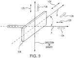
- FIG. 1 a partial view of an exemplary embodiment of an additive manufacturing system in accordance with the disclosure is shown in Fig. 1 and is designated generally by reference character 100.
- FIGs. 2 - 7 Other embodiments of additive manufacturing systems and methods of depositing powder in additive manufacturing systems in accordance with the disclosure, or aspects thereof, are provided in Figs. 2 - 7 , as will be described.
- the systems and methods described herein can be used for smoothing powder in additive manufacturing system build chambers, though the present disclosure is not limited to powder smoothing or to additive manufacturing in general.
- Fig. 1 schematically illustrates additive manufacturing system 100.
- Exemplary additive manufacturing system 100 may include a stereolithographic apparatus, a direct selective laser sintering apparatus, an electron beam sintering apparatus, an electron beam melting apparatus, a laser engineered net shaping apparatus, a laser net shape manufacturing apparatus, a direct metal deposition apparatus, or a direct metal laser sintering apparatus by way of non-limiting example.
- Additive manufacturing system 100 includes a build chamber 102, a charging module 104, a recoater 106, and an energy beam source 120.
- Build chamber 102 and charging module 104 are disposed along a drive axis A.
- Recoater 106 is movable along drive axis A between charging module 104 and build chamber 102 to smooth a powder 10 provided by charging module 104 in build chamber 102.
- Energy beam source 120 is configured to project an energy beam 122 over powder 10, thereby fusing a portion of powder 10 into successive layers of an article 12.
- Additive manufacturing system 100 also includes one or more of a control module 108, a drive module 110, an oscillation module 112, a vibration module 114, and a pitching/yawing module 116.
- Control module 108 is communicative with drive module 110, oscillation module 112, vibration module 114, pitching/yawing module 116, and/or energy beam source 120.
- Drive module 110 is operably connected to recoater module 106 and is configured and adapted to drive recoater 106 along drive axis A.
- Oscillation module 112 is operably connected to recoater 106 and is configured and adapted to oscillate recoater 106 with one or more oscillatory components along an oscillation axis B (shown in Fig.
- Vibration module 114 is operably connected to recoater 106 and is configured and adapted to vibrate recoater 106 with one or more vibratory components along oscillation axis B while recoater 106 is driven along drive axis A.
- Pitching/yawing module 116 is operably connected to recoater 106 is configured and adapted to pitch or yaw recoater 106 relative to drive axis A.
- Recoater 106 includes one or more of a roller 120 and a blade 122, which may be rigid or non-rigid in construction, and which may have two or more degrees of freedom.
- recoater 106 is movable along both drive axis A and oscillation axis B.
- oscillatory movement of recoater 106 may include to and from movement along a single axis, e.g., drive axis A, oscillation axis B, or relative to the direction of gravity, whereas vibratory movement of recoater 106 may be in two or more directions, for example having a movement component in two directions including drive axis A, oscillation axis B, and/or the direction of gravity.
- Pitching/yawing module 118 is configured and adapted to pitch or yaw recoater 106 relative to drive axis A at a pitch angle 124 and/or a yaw angle 126.
- Pitch angle 124 and/yaw angle 126 can be during a given movement of recoater 106 along drive axis A across build chamber 102.
- Pitch angle 124 and/or yaw angle 126 can be varied, and in embodiments continuously varied, as recoater 106 moves along drive axis A. Varying pitch angle 124 and/or yaw angle 126 can change the direction of force applied to particles while smoothing, improving smoothing by increasing the tendency of particulate forming powder 10 to separate from one another.
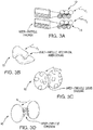
- powder 10 has a constitution influenced by the discrete particles of constitution characterized by one or more of size (or size distribution), shape (e.g., spherical, irregular, ellipsoid, jagged, etc.), and composition (e.g., titanium-containing, etc.).
- the particulate forming powder 10 may have a composition that includes titanium.
- the particulate forming powder 10 may have a non-spherical shape.
- the particulate forming powder 10 may have a particulate size, e.g., a mean particle size, that is between about forty (40) microns and about fifty (50) microns is size.
- the one or more of the particle composition, shape, and size may influence the particle movement restriction mechanism of the powder.
- FIG. 3A frictional adherence between particles of an exemplary powder having spherical shape are shown being overcome by an oscillatory or vibratory force F 1 /F 2 .
- FIG. 3B adherence from mechanical interlock of irregularly-shaped (e.g., jagged) particles of an exemplary powder by an oscillatory or vibratory force F 3 .
- Fig. 3C adherence from liquid bridging between particles of an exemplary powder are shown being overcome by an oscillatory or vibratory force F 4 .
- Fig. 3D adherence from cohesion between particles of an exemplary powder 10 are shown being overcome by an oscillatory or vibratory force F 5 .
- the oscillation or vibratory motion of recoater 106 (shown in Fig. 1 ) be selected according to a powder movement restriction mechanism of powder 10.
- a powder movement restriction mechanism of powder 10 For example, one or more of oscillation frequency, oscillation direction, and/or oscillation magnitude may be selected by controller 106 according to an association with a particular powder constitution and stored in a module 118, which may be a lookup table by way of non-limiting example.
- a vibration frequency, vibration direction, and/or vibration magnitude may be selected by controller 106 according to a predetermined association with a particular powder constitution, which is stored in module 118 as a lookup table.
- oscillating recoater 106 includes vibrating recoater 106 with a frequency that is between about five (5) hertz and about 300 hertz, which can improve the uniformity of powders including titanium and/or powder having particulate of non-spherical shapes.
- recoater 106 is disposed along drive axis A and defines an oscillation axis B.
- Recoater 106 has at least two degrees of freedom, a first degree of freedom being disposed along drive axis A and a second degree of freedom being disposed along oscillation axis B.
- recoater 106 is configured and adapted to oscillate along oscillation axis B while recoater 106 is driven along drive axis A.
- recoater 106 may oscillate with an oscillation component 128 that is aligned relative to drive axis A.
- Recoater 106 may oscillate with an oscillation component 130 that is oriented laterally relative to the direction of gravity.
- Recoater 106 may oscillate with an oscillation component 132 that is oriented vertically relative to the direction of gravity.
- the orientation, magnitude, and frequency of the oscillation may be selected according to one or more of the particle movement restriction mechanism of the particulate forming the powder being smoothed within build chamber 102 (shown in Fig. 1 ).
- recoater 106 may alternatively or additionally be configured and adapted to vibrate along oscillation axis B while recoater 106 is driven along drive axis A.
- the vibration may have a vibratory component 134 that is aligned relative to drive axis A.
- the vibration may have a vibratory component that is not aligned relative to the drive axis A.
- the vibration may have a vibratory component 136 that is oriented laterally relative to the direction of gravity.
- the vibration may have a vibratory component 138 that is oriented vertically relative to the direction of gravity.
- the orientation, magnitude, and frequency of the vibration may be selected according to one or more of the particle movement restriction mechanism (shown in Figs. 3A-3D ) of the particulate forming powder 10 as it is smoothed within build chamber 102 (shown in Fig. 1 ).
- Method 200 includes depositing powder, e.g., powder 10 (shown in Fig. 1 ) along a drive axis, e.g., drive axis A (shown in Fig. 1 ), as shown with box 210.
- the powder can include titanium, may have particle having non-spherical shape, and sizes in the range of forty (40) microns and about fifty (50) microns.
- Method 200 includes driving the recoater along the drive axis, as shown with box 220.
- the recoater may be pitched relative to the drive axis, as shown with box 230.
- the recoater may be yawed relative to the drive axis, as shown with box 240.
- the yaw and/or pitch angle may be selected to overcome an attribute of the particle that otherwise limits the ability of the recoater to smooth the powder in the build chamber, such as particle size, particle composition, and/or particle shape.
- the yaw angle and/or pitch angle may be selected to overcome one or more particle movement restriction mechanisms of the powder, such as friction, mechanical interlocking, liquid bridging, and inter-particle cohesion, thereby allowing the recoater to smooth the powder layer deposited in the build chamber.
- the recoater may be oscillated, as shown with box 250.
- the recoater may be vibrated, as shown with box 260. It is contemplated that the oscillation and or vibration be continuous as the recoater recoats the build chamber.
- oscillating 250 the recoater can include oscillating the recoater along the oscillation axis as the recoater is driven along the drive axis.
- the oscillation may have an oscillation component that is in a direction that is aligned to the drive axis, as shown with box 252.
- the oscillation may have an oscillation component that is in a direction that is not aligned to the drive axis, as shown with box 254.
- Oscillation may be with a lateral component relative to the direction of gravity, as shown with box 256.
- Oscillation may be with a vertical component relative to the direction of gravity, as shown with box 258.
- One or more of the oscillation direction, magnitude, and/or frequency can be selected according to the constitution of the powder smoothed by the recoater, such as based upon the material composition of the particulate, the size of the particulate forming the particulate, and/or the shape of particles forming the powder, as shown with box 258.
- the oscillation direction and/or magnitude can be selected to overcome one or more particle movement restriction mechanisms of the powder, such as friction, mechanical interlocking, liquid bridging, and inter-particle cohesion, thereby allowing the recoater to smooth the powder layer deposited in the build chamber.
- vibrating 260 the recoater may include vibrating the recoater with a vibratory component extending along the drive axis, as shown with box 262.
- Vibrating the recoater may include vibrating the recoater with a vibratory component that is at an angle relative to the drive axis, as shown with box 264.
- the recoater can be vibrated with a vibratory component that is lateral relative to the drive axis, as shown with box 266.
- the recoater can be vibrated with a vertical component relative to the direction of gravity, as shown with box 268.
- One or more of the vibratory direction, magnitude, and/or frequency can be selected according to the constitution of the powder smoothed by the recoater, such as based upon the material composition of the particulate, the size of the particulate forming the particulate, and/or the shape of particles forming the powder, as shown with box 269.
- the vibratory direction and/or magnitude can be selected to overcome one or more particle movement restriction mechanisms of the powder, such as friction, mechanical interlocking, liquid bridging, and inter-particle cohesion, thereby allowing the recoater to smooth the powder layer deposited in the build chamber.
Landscapes
- Engineering & Computer Science (AREA)
- Chemical & Material Sciences (AREA)
- Materials Engineering (AREA)
- Manufacturing & Machinery (AREA)
- Physics & Mathematics (AREA)
- Optics & Photonics (AREA)
- Mechanical Engineering (AREA)
- Automation & Control Theory (AREA)
- Powder Metallurgy (AREA)
Description
- The present disclosure relates generally to additive manufacturing, and more particularly to depositing powder in additive manufacturing system build chambers.
- Additive manufacturing techniques are commonly used to fabricate articles by projecting an energy beam on a powder bed. The beam is generally moved across the powder bed such that a portion of the powder fuses, thereby forming a layer of an article. Once the layer is formed, the powder bed is refreshed by spreading new powder across the fused layer, and a subsequent layer formed by fusing a portion of the added powder to the underlying layer.
- In some additive manufacturing techniques, the uniformity of powder spread within the build chamber can influence mechanical properties of articles produced using the technique. For example, some powders tend to clump together as the powder is spread across the fused layer. One approach to this challenge is to carefully control the shape of particulate forming the powder, such as by forming the particulate with spherical shapes, which are generally less apt to interlock and/or adhere to one another while being spread across the fused layer. While spherically shaped particles can generally be spread with good uniformity, generating such powders can be relatively expensive and/or can require specialized powder generation equipment, like plasma rotating electrode generators, instead of more common powder generation equipment.
- Such conventional methods and systems have generally been considered satisfactory for their intended purpose. Various other solutions to improve the spread and flatness of the powder bed have been suggested such as by vibration, as in e.g..
EP3165304 A1 ,DE4325573 A1 ,US6387380 , "Powder layer position accuracy in powder-based rapid prototyping" (S.-J.J.Lee e.a. in Solid Freeform Fabrication Symposium Proceedings, 1993, pp.223-236), or alternatively by oscillation, as in e.g.US2004/0170765 A1 . However, there is still a need in the art for improved systems and methods for depositing powder in additive manufacturing system build chambers. The present disclosure provides a solution for this need. - A method of depositing powder in an additive manufacturing system includes driving a recoater along a drive axis and oscillating the recoater along an oscillation axis. The recoater is oscillated along the oscillation axis while the recoater is driven along the drive axis to overcome the effect of one or more particle movement restriction mechanisms for smoothing powder deposited in a build chamber of an additive manufacturing system, and by pitching or yawing the recoater relative to the drive axis.
- In certain embodiments, oscillating the recoater along the oscillation axis can include overcoming inter-particle forces associated with particle movement restriction mechanisms like friction, interlock, liquid bridging, and/or cohesion. The method can include smoothing the powder by oscillating the recoater along the oscillation axis. The powder can have particulate with titanium or alloys thereof. The powder can have particulate with non-spherical shapes. The recoater can smooth the powder while pitched or yawed relative to the drive axis.
- In accordance with certain embodiments, oscillating the recoater can include oscillating the recoater as the recoater reciprocates along the drive axis. Oscillating the recoater can include oscillating the recoater along the drive axis. Oscillating the recoater can include oscillating the recoater in a direction angled relative to the drive axis. Oscillating the recoater can include oscillating the recoater laterally relative to the drive axis. Oscillating the recoater can include oscillating the recoater vertically relative to the direction of gravity. One or more of the oscillation frequency, oscillation direction, and oscillation magnitude can be selected according to a constitution of the powder or size of the additive manufacturing system build chamber.
- It is also contemplated that, in accordance with certain embodiments, oscillating the recoater can include vibrating the recoater. The recoater can be vibrated in the direction of the drive axis, at an angle relative to the drive axis, laterally relative to the drive axis, and/or vertically relative to the direction of gravity. The method can include selecting one or more of a vibration frequency, vibration direction, and/or a vibration magnitude based on a constitution of the powder or size of an additive manufacturing system build chamber. The vibration can be in a frequency range between about five (5) hertz and about 300 hertz.
- An additive manufacturing system includes a recoater having a drive axis and an oscillation axis, a build chamber disposed along the drive axis, and a drive module operably connected to the recoater to drive the recoater along the drive axis. An oscillation module is operably connected to the recoater to oscillate the recoater along the oscillation axis. A control module is communicative with the drive module, the pitching/yawing module and the oscillation module and is configured to select one or more of an oscillation direction, oscillation frequency, and oscillation magnitude according to constitution of a powder in the build chamber, and further comprising a charging module disposed along the drive axis, and one or more of a pitching /yawing module operably connected to the recoater and configured and adapted to pitch or yaw the recoater relative to the drive axis, at a pitch and/ or yaw angle. In certain embodiments, the oscillation axis can be aligned with or angled to the drive axis. The recoater can have at least two degrees of freedom. The recoater can be a non-rigid recoater, and can include a blade or a roller.
- These and other features of the systems and methods of the subject disclosure will become more readily apparent to those skilled in the art from the following detailed description of the preferred embodiments taken in conjunction with the drawings.
- So that those skilled in the art to which the subject disclosure appertains will readily understand how to make and use the devices and methods of the subject disclosure without undue experimentation, embodiments thereof will be described in detail herein below with reference to certain figures, wherein:
-
Fig. 1 is a schematic perspective view of an exemplary embodiment of an additive manufacturing system constructed in accordance with the present disclosure, showing a recoater; -
Fig. 2 is schematic side elevation view of the recoater ofFig. 1 , showing recoaters including a non-rigid blade and a non-rigid roller, respectively, according to embodiments; -
Figs. 3A-3D show force exerted upon discrete particles of a powder disposed within the additive manufacturing system ofFig. 1 , showing the forces overcoming particle movement restriction mechanisms of the powder, according to embodiments; -
Fig. 4 is a is a schematic view of the recoater ofFig. 1 , showing oscillation and vibration of the recoater, according to embodiments; - Fig. 5 is a diagram of a method of depositing powder in an additive manufacturing system, showing steps of the method;
-
Fig. 6 is a diagram showing the method ofFig. 4 , showing steps for oscillating a recoater to smooth powder deposited in an additive manufacturing system build chamber, according to embodiments; and -
Fig. 7 is a diagram showing the method ofFig. 4 , showing steps for vibrating a recoater to smooth powder deposited in an additive manufacturing system build chamber, according to embodiments. - Reference will now be made to the drawings wherein like reference numerals identify similar structural features or aspects of the subject disclosure. For purposes of explanation and illustration, and not limitation, a partial view of an exemplary embodiment of an additive manufacturing system in accordance with the disclosure is shown in
Fig. 1 and is designated generally byreference character 100. Other embodiments of additive manufacturing systems and methods of depositing powder in additive manufacturing systems in accordance with the disclosure, or aspects thereof, are provided inFigs. 2 - 7 , as will be described. The systems and methods described herein can be used for smoothing powder in additive manufacturing system build chambers, though the present disclosure is not limited to powder smoothing or to additive manufacturing in general. -
Fig. 1 schematically illustratesadditive manufacturing system 100. Exemplaryadditive manufacturing system 100 may include a stereolithographic apparatus, a direct selective laser sintering apparatus, an electron beam sintering apparatus, an electron beam melting apparatus, a laser engineered net shaping apparatus, a laser net shape manufacturing apparatus, a direct metal deposition apparatus, or a direct metal laser sintering apparatus by way of non-limiting example. -
Additive manufacturing system 100 includes abuild chamber 102, acharging module 104, arecoater 106, and anenergy beam source 120.Build chamber 102 andcharging module 104 are disposed along a driveaxis A. Recoater 106 is movable along drive axis A betweencharging module 104 andbuild chamber 102 to smooth apowder 10 provided bycharging module 104 inbuild chamber 102.Energy beam source 120 is configured to project anenergy beam 122 overpowder 10, thereby fusing a portion ofpowder 10 into successive layers of anarticle 12. -
Additive manufacturing system 100 also includes one or more of acontrol module 108, adrive module 110, anoscillation module 112, avibration module 114, and a pitching/yawing module 116.Control module 108 is communicative withdrive module 110,oscillation module 112,vibration module 114, pitching/yawing module 116, and/orenergy beam source 120.Drive module 110 is operably connected torecoater module 106 and is configured and adapted to driverecoater 106 along drive axisA. Oscillation module 112 is operably connected torecoater 106 and is configured and adapted tooscillate recoater 106 with one or more oscillatory components along an oscillation axis B (shown inFig. 4 ) whilerecoater 106 is driven along drive axisA. Vibration module 114 is operably connected torecoater 106 and is configured and adapted to vibraterecoater 106 with one or more vibratory components along oscillation axis B whilerecoater 106 is driven along drive axis A. Pitching/yawing module 116 is operably connected torecoater 106 is configured and adapted to pitch oryaw recoater 106 relative to drive axis A. - With reference to
Fig. 2 ,recoater 106 is shown.Recoater 106 includes one or more of aroller 120 and ablade 122, which may be rigid or non-rigid in construction, and which may have two or more degrees of freedom. For example,recoater 106 is movable along both drive axis A and oscillation axis B. As will be appreciated by those of skill in the art in view of the present disclosure, it is contemplated that oscillatory movement ofrecoater 106 may include to and from movement along a single axis, e.g., drive axis A, oscillation axis B, or relative to the direction of gravity, whereas vibratory movement ofrecoater 106 may be in two or more directions, for example having a movement component in two directions including drive axis A, oscillation axis B, and/or the direction of gravity. - Pitching/
yawing module 118 is configured and adapted to pitch oryaw recoater 106 relative to drive axis A at apitch angle 124 and/or ayaw angle 126.Pitch angle 124 and/yaw angle 126 can be during a given movement ofrecoater 106 along drive axis A acrossbuild chamber 102.Pitch angle 124 and/oryaw angle 126 can be varied, and in embodiments continuously varied, asrecoater 106 moves along drive axis A. Varyingpitch angle 124 and/oryaw angle 126 can change the direction of force applied to particles while smoothing, improving smoothing by increasing the tendency of particulate formingpowder 10 to separate from one another. - Referring the
Figs. 3A -- 3D ,powder 10 has a constitution influenced by the discrete particles of constitution characterized by one or more of size (or size distribution), shape (e.g., spherical, irregular, ellipsoid, jagged, etc.), and composition (e.g., titanium-containing, etc.). In certain embodiments theparticulate forming powder 10 may have a composition that includes titanium. Theparticulate forming powder 10 may have a non-spherical shape. Theparticulate forming powder 10 may have a particulate size, e.g., a mean particle size, that is between about forty (40) microns and about fifty (50) microns is size. As will be appreciated by those of skill in the art in view of the present disclosure, the one or more of the particle composition, shape, and size may influence the particle movement restriction mechanism of the powder. - With respect to
Fig. 3A , frictional adherence between particles of an exemplary powder having spherical shape are shown being overcome by an oscillatory or vibratory force F1/F2. With respect toFig. 3B , adherence from mechanical interlock of irregularly-shaped (e.g., jagged) particles of an exemplary powder by an oscillatory or vibratory force F3. With respect toFig. 3C , adherence from liquid bridging between particles of an exemplary powder are shown being overcome by an oscillatory or vibratory force F4. With respect toFig. 3D , adherence from cohesion between particles of anexemplary powder 10 are shown being overcome by an oscillatory or vibratory force F5. Overcoming the forces associated with one or more of the illustrated exemplary particle movement restriction mechanisms renderspowder 10 more apt to smooth uniformly during spreading (i.e. recoating) by fluidizing the particulate. Fluidization of particulate formingpowder 10 potentially improves the mechanical characteristics of articles constructed from the smoothed powder, e.g., article 12 (shown inFig. 1 ). - It is contemplated that the oscillation or vibratory motion of recoater 106 (shown in
Fig. 1 ) be selected according to a powder movement restriction mechanism ofpowder 10. For example, one or more of oscillation frequency, oscillation direction, and/or oscillation magnitude may be selected bycontroller 106 according to an association with a particular powder constitution and stored in amodule 118, which may be a lookup table by way of non-limiting example. One or more of a vibration frequency, vibration direction, and/or vibration magnitude may be selected bycontroller 106 according to a predetermined association with a particular powder constitution, which is stored inmodule 118 as a lookup table. As will be appreciated by those of skill in the art in view of the present disclosure, the associations can be arrived at through experimentation for a given additive manufacturing technique, powder constitution, and/or build chamber size. In an exemplary embodiment, oscillatingrecoater 106 includes vibratingrecoater 106 with a frequency that is between about five (5) hertz and about 300 hertz, which can improve the uniformity of powders including titanium and/or powder having particulate of non-spherical shapes. - With reference to
Fig. 4 ,recoater 106 is disposed along drive axis A and defines an oscillationaxis B. Recoater 106 has at least two degrees of freedom, a first degree of freedom being disposed along drive axis A and a second degree of freedom being disposed along oscillation axis B. In certain embodiments,recoater 106 is configured and adapted to oscillate along oscillation axis B whilerecoater 106 is driven along drive axis A. In thisrespect recoater 106 may oscillate with anoscillation component 128 that is aligned relative to driveaxis A. Recoater 106 may oscillate with anoscillation component 130 that is oriented laterally relative to the direction of gravity.Recoater 106 may oscillate with anoscillation component 132 that is oriented vertically relative to the direction of gravity. The orientation, magnitude, and frequency of the oscillation may be selected according to one or more of the particle movement restriction mechanism of the particulate forming the powder being smoothed within build chamber 102 (shown inFig. 1 ). - In accordance within certain embodiments,
recoater 106 may alternatively or additionally be configured and adapted to vibrate along oscillation axis B whilerecoater 106 is driven along drive axis A. The vibration may have avibratory component 134 that is aligned relative to drive axis A. The vibration may have a vibratory component that is not aligned relative to the drive axis A. For example, the vibration may have avibratory component 136 that is oriented laterally relative to the direction of gravity. The vibration may have avibratory component 138 that is oriented vertically relative to the direction of gravity. The orientation, magnitude, and frequency of the vibration may be selected according to one or more of the particle movement restriction mechanism (shown inFigs. 3A-3D ) of theparticulate forming powder 10 as it is smoothed within build chamber 102 (shown inFig. 1 ). - Referring to Fig. 5, a
method 200 of depositing powder in an additive manufacturing system build chamber is shown.Method 200 includes depositing powder, e.g., powder 10 (shown inFig. 1 ) along a drive axis, e.g., drive axis A (shown inFig. 1 ), as shown withbox 210. The powder can include titanium, may have particle having non-spherical shape, and sizes in the range of forty (40) microns and about fifty (50) microns. -
Method 200 includes driving the recoater along the drive axis, as shown withbox 220. As the recoater is driven along the drive axis, the recoater may be pitched relative to the drive axis, as shown withbox 230. As the recoater is driven along the drive axis, the recoater may be yawed relative to the drive axis, as shown withbox 240. The yaw and/or pitch angle may be selected to overcome an attribute of the particle that otherwise limits the ability of the recoater to smooth the powder in the build chamber, such as particle size, particle composition, and/or particle shape. The yaw angle and/or pitch angle may be selected to overcome one or more particle movement restriction mechanisms of the powder, such as friction, mechanical interlocking, liquid bridging, and inter-particle cohesion, thereby allowing the recoater to smooth the powder layer deposited in the build chamber. As the recoater is driven the along the drive axis the recoater may be oscillated, as shown withbox 250. As the recoater is driven along the drive axis the recoater may be vibrated, as shown withbox 260. It is contemplated that the oscillation and or vibration be continuous as the recoater recoats the build chamber. - With reference to
Fig. 6 , oscillating 250 the recoater can include oscillating the recoater along the oscillation axis as the recoater is driven along the drive axis. The oscillation may have an oscillation component that is in a direction that is aligned to the drive axis, as shown withbox 252. The oscillation may have an oscillation component that is in a direction that is not aligned to the drive axis, as shown with box 254. Oscillation may be with a lateral component relative to the direction of gravity, as shown withbox 256. Oscillation may be with a vertical component relative to the direction of gravity, as shown withbox 258. - One or more of the oscillation direction, magnitude, and/or frequency can be selected according to the constitution of the powder smoothed by the recoater, such as based upon the material composition of the particulate, the size of the particulate forming the particulate, and/or the shape of particles forming the powder, as shown with
box 258. The oscillation direction and/or magnitude can be selected to overcome one or more particle movement restriction mechanisms of the powder, such as friction, mechanical interlocking, liquid bridging, and inter-particle cohesion, thereby allowing the recoater to smooth the powder layer deposited in the build chamber. - Referring to
Fig. 7 , vibrating 260 the recoater may include vibrating the recoater with a vibratory component extending along the drive axis, as shown withbox 262. Vibrating the recoater may include vibrating the recoater with a vibratory component that is at an angle relative to the drive axis, as shown withbox 264. The recoater can be vibrated with a vibratory component that is lateral relative to the drive axis, as shown withbox 266. The recoater can be vibrated with a vertical component relative to the direction of gravity, as shown withbox 268. - One or more of the vibratory direction, magnitude, and/or frequency can be selected according to the constitution of the powder smoothed by the recoater, such as based upon the material composition of the particulate, the size of the particulate forming the particulate, and/or the shape of particles forming the powder, as shown with
box 269. The vibratory direction and/or magnitude can be selected to overcome one or more particle movement restriction mechanisms of the powder, such as friction, mechanical interlocking, liquid bridging, and inter-particle cohesion, thereby allowing the recoater to smooth the powder layer deposited in the build chamber. - The methods and systems of the present disclosure, as described above and shown in the drawings, provide for additive manufacturing methods and systems with superior properties including the capability to smooth powders with non-spherically shaped particulate within the build chamber of an additive manufacturing system, reducing the manufacturing costs and complexity of certain types of powder feedstock for additive manufacturing techniques. While the apparatus and methods of the subject disclosure have been shown and described with reference to preferred embodiments, those skilled in the art will readily appreciate that changes and/or modifications may be made thereto without departing from the scope of the subject invention as defined by the claims.
Claims (12)
- A method of depositing powder (10) in an additive manufacturing system, comprising:driving a recoater (106) along a drive axis (A); andoscillating the recoater along an oscillation axis (B) while driving the recoater along the drive axis to overcome the effect of one or more particle movement restriction mechanisms and smooth the powder (10) in a build chamber (102) of an additive manufacturing system; and characterised by pitching or yawing the recoater relative to the drive axis.
- A method as recited in claim 1, wherein oscillating the recoater (106) further comprises overcoming one or more of inter-particle friction, inter-particle interlocking, inter-particle liquid bridging, and inter-particle cohesion.
- A method as recited in claim 1 or 2, wherein oscillating the recoater (106) comprises oscillating the recoater along the drive axis, and/or wherein oscillating the recoater (106) comprises oscillating the recoater in a direction angled relative to the drive axis, and/or wherein oscillating the recoater (106) comprises oscillating the recoater laterally relative to the drive axis, and/or wherein oscillating the recoater (106) comprises oscillating the recoater vertically relative to the direction of gravity.
- A method as recited in any preceding claim, further comprising selecting at least one of an oscillation frequency, an oscillation direction, and an oscillation magnitude is based on a constitution of the powder or size of an additive manufacturing system build chamber.
- A method as recited in any preceding claim, wherein oscillating the recoater comprises vibrating the recoater.
- A method as recited in claim 5, wherein vibrating the recoater comprises at least one of (a) vibrating the recoater in the direction of the drive axis, (b) vibrating the recoater at an angle relative to the drive axis, (c) vibrating the recoater laterally relative to the drive axis, and (d) vibrating the recoater vertically relative to the direction of gravity.
- A method as recited in claim 6, wherein vibrating the recoater comprises selecting at least one of a vibration frequency, vibration direction, and a vibration magnitude based on a constitution of the powder or size of an additive manufacturing system build chamber.
- A method as recited in any preceding claim, wherein oscillating the recoater comprises vibrating the recoater with a frequency that is between about five (5) hertz and about 300 hertz.
- A method as recited in any preceding claim, wherein oscillating the recoater further comprises oscillating the recoater as the recoater reciprocates along the drive axis.
- An additive manufacturing system, comprising:a recoater (106) having an drive axis (A) and an oscillation axis (B);a build chamber (102) disposed along the drive axis;a drive module (110) operably connected to the recoater to drive the recoater along the drive axis;an oscillation module (112) operably connected to the recoater to oscillate the recoater along the oscillation axis; anda control module (108) communicative with the drive module, the pitching/yawing module (116) and the oscillation module and configured to select one or more of an oscillation direction, frequency, and/or magnitude according to constitution of a powder disposed within the build chamber; and further comprisinga charging module (104) disposed along the drive axis, and one or more of a pitching or yawing module operably connected to the recoater and configured and adapted to pitch or yaw the recoater relative to the drive axis (A), at a pitch (124) and/or yaw (126) angle.
- An additive manufacturing system as recited in claim 10, wherein the oscillation axis is aligned with the drive axis or angled relative to the drive axis.
- An additive manufacturing system as recited in claim 10, wherein the recoater is a non-rigid recoater including a blade or a roller.
Priority Applications (1)
| Application Number | Priority Date | Filing Date | Title |
|---|---|---|---|
| EP19187350.4A EP3575019B1 (en) | 2016-05-10 | 2017-05-10 | Additive manufacturing system |
Applications Claiming Priority (1)
| Application Number | Priority Date | Filing Date | Title |
|---|---|---|---|
| US15/151,311 US10518478B2 (en) | 2016-05-10 | 2016-05-10 | Additive manufacturing systems and methods |
Related Child Applications (1)
| Application Number | Title | Priority Date | Filing Date |
|---|---|---|---|
| EP19187350.4A Division EP3575019B1 (en) | 2016-05-10 | 2017-05-10 | Additive manufacturing system |
Publications (2)
| Publication Number | Publication Date |
|---|---|
| EP3243584A1 EP3243584A1 (en) | 2017-11-15 |
| EP3243584B1 true EP3243584B1 (en) | 2019-07-31 |
Family
ID=58701464
Family Applications (2)
| Application Number | Title | Priority Date | Filing Date |
|---|---|---|---|
| EP19187350.4A Active EP3575019B1 (en) | 2016-05-10 | 2017-05-10 | Additive manufacturing system |
| EP17170379.6A Active EP3243584B1 (en) | 2016-05-10 | 2017-05-10 | Additive manufacturing systems and methods |
Family Applications Before (1)
| Application Number | Title | Priority Date | Filing Date |
|---|---|---|---|
| EP19187350.4A Active EP3575019B1 (en) | 2016-05-10 | 2017-05-10 | Additive manufacturing system |
Country Status (2)
| Country | Link |
|---|---|
| US (2) | US10518478B2 (en) |
| EP (2) | EP3575019B1 (en) |
Families Citing this family (8)
| Publication number | Priority date | Publication date | Assignee | Title |
|---|---|---|---|---|
| DE102015202347A1 (en) * | 2015-02-10 | 2016-08-11 | Trumpf Laser- Und Systemtechnik Gmbh | Irradiation device, processing machine and method for producing a layer of a three-dimensional component |
| US11597147B2 (en) | 2018-07-31 | 2023-03-07 | Hewlett-Packard Development Company, L.P. | Ultrasonic spreading blades with kickers |
| EP3774292B1 (en) * | 2018-10-12 | 2023-04-26 | Hewlett-Packard Development Company, L.P. | Frequency control of spreader vibrations |
| EP3741542A1 (en) | 2019-05-20 | 2020-11-25 | LayerWise N.V. | Three-dimensional printing system with self-maintaining powder distribution subsystem |
| CN114126843A (en) * | 2019-05-28 | 2022-03-01 | 伏尔肯模型公司 | Recoater system for additive manufacturing |
| US20200376773A1 (en) * | 2019-05-28 | 2020-12-03 | Vulcanforms Inc. | Recoater system for additive manufacturing |
| DE102020004503A1 (en) | 2020-07-24 | 2022-01-27 | Aixway3D GmbH | Device and method for improved powder application in an additive manufacturing process |
| EP3943219A1 (en) * | 2020-07-24 | 2022-01-26 | Aixway3D GmbH | Device and method for improved powder application in an additive manufacturing method |
Family Cites Families (8)
| Publication number | Priority date | Publication date | Assignee | Title |
|---|---|---|---|---|
| US5387380A (en) | 1989-12-08 | 1995-02-07 | Massachusetts Institute Of Technology | Three-dimensional printing techniques |
| DE4325573C2 (en) | 1993-07-30 | 1998-09-03 | Stephan Herrmann | Process for the production of moldings by successive build-up of powder layers and device for its implementation |
| DE10117875C1 (en) | 2001-04-10 | 2003-01-30 | Generis Gmbh | Method, device for applying fluids and use of such a device |
| GB0712027D0 (en) | 2007-06-21 | 2007-08-01 | Materials Solutions | Rotating build plate |
| WO2013167194A1 (en) * | 2012-05-11 | 2013-11-14 | Arcam Ab | Powder distribution in additive manufacturing |
| JP2015533650A (en) | 2012-07-27 | 2015-11-26 | エアロジェット ロケットダイン オブ ディーイー,インコーポレイテッド | Selective laser melting solid axisymmetric powder bed. |
| EP3151782B1 (en) * | 2014-06-06 | 2018-12-26 | 3M Innovative Properties Company | A device for powder based additive material manufacturing of dental appliances |
| JP2017087469A (en) | 2015-11-04 | 2017-05-25 | 株式会社リコー | Apparatus for three-dimensional fabrication |
-
2016
- 2016-05-10 US US15/151,311 patent/US10518478B2/en active Active
-
2017
- 2017-05-10 EP EP19187350.4A patent/EP3575019B1/en active Active
- 2017-05-10 EP EP17170379.6A patent/EP3243584B1/en active Active
-
2019
- 2019-11-21 US US16/690,945 patent/US11413825B2/en active Active
Non-Patent Citations (1)
| Title |
|---|
| None * |
Also Published As
| Publication number | Publication date |
|---|---|
| US20170326806A1 (en) | 2017-11-16 |
| US10518478B2 (en) | 2019-12-31 |
| EP3575019B1 (en) | 2021-09-15 |
| EP3243584A1 (en) | 2017-11-15 |
| US20200164587A1 (en) | 2020-05-28 |
| US11413825B2 (en) | 2022-08-16 |
| EP3575019A1 (en) | 2019-12-04 |
Similar Documents
| Publication | Publication Date | Title |
|---|---|---|
| EP3243584B1 (en) | Additive manufacturing systems and methods | |
| KR102458119B1 (en) | Multiple Materials and Printing Parameters for Additive Manufacturing | |
| CN108349001B (en) | Additive manufacturing system and method utilizing localized ultrasonic enhanced material flow and fusion | |
| US10882110B2 (en) | Method and device for applying fluids | |
| Zhang et al. | Weld deposition-based rapid prototyping: a preliminary study | |
| JP5740716B2 (en) | Manufacturing method of three-dimensional structure | |
| US20220266342A1 (en) | Method of determining a tool path for controlling a printing tool | |
| JP6303016B2 (en) | Manufacturing method of layered objects | |
| WO2016196382A1 (en) | Three-dimensional printing and three-dimensional objects formed using the same | |
| US20170326792A1 (en) | Method, Device, and Recoating Module for Producing a Three-Dimensional Object | |
| GB2459262A (en) | Particle damper constuction | |
| US6027699A (en) | Material forming apparatus using a directed droplet stream | |
| JP2006200030A (en) | Method and device for producing cubic molding | |
| EP3094411B1 (en) | Particle separator for an additive manufacturing system and method of operation | |
| US20170216918A1 (en) | Methods and systems for fabrication using multi-material and precision alloy droplet jetting | |
| CN215144707U (en) | Equipment system for improving powder bed quality in additive manufacturing process | |
| JP6875446B2 (en) | Method of additively manufacturing at least one 3D object | |
| JP2019077939A (en) | Lamination molding device | |
| EP3444051B1 (en) | Movable wall for additive powder bed | |
| US11446868B2 (en) | Assembly and method for creating a 3D structure | |
| TW201922600A (en) | Supply apparatus, processing system and processing method | |
| KR101582739B1 (en) | 3D-forming machine and control method thereof | |
| US11344949B2 (en) | Powder removal floating structures | |
| JP6768459B2 (en) | Three-dimensional laminated molding method and three-dimensional laminated molding equipment | |
| EP2865479A1 (en) | Method and system for generating a component using thermal spraying and laser fusing |
Legal Events
| Date | Code | Title | Description |
|---|---|---|---|
| PUAI | Public reference made under article 153(3) epc to a published international application that has entered the european phase |
Free format text: ORIGINAL CODE: 0009012 |
|
| STAA | Information on the status of an ep patent application or granted ep patent |
Free format text: STATUS: THE APPLICATION HAS BEEN PUBLISHED |
|
| AK | Designated contracting states |
Kind code of ref document: A1 Designated state(s): AL AT BE BG CH CY CZ DE DK EE ES FI FR GB GR HR HU IE IS IT LI LT LU LV MC MK MT NL NO PL PT RO RS SE SI SK SM TR |
|
| AX | Request for extension of the european patent |
Extension state: BA ME |
|
| STAA | Information on the status of an ep patent application or granted ep patent |
Free format text: STATUS: REQUEST FOR EXAMINATION WAS MADE |
|
| 17P | Request for examination filed |
Effective date: 20180515 |
|
| RBV | Designated contracting states (corrected) |
Designated state(s): AL AT BE BG CH CY CZ DE DK EE ES FI FR GB GR HR HU IE IS IT LI LT LU LV MC MK MT NL NO PL PT RO RS SE SI SK SM TR |
|
| RIC1 | Information provided on ipc code assigned before grant |
Ipc: B33Y 30/00 20150101ALI20181218BHEP Ipc: B29C 64/205 20170101ALI20181218BHEP Ipc: B22F 3/105 20060101AFI20181218BHEP Ipc: B29C 64/153 20170101ALI20181218BHEP Ipc: B33Y 10/00 20150101ALI20181218BHEP Ipc: B29C 64/321 20170101ALI20181218BHEP |
|
| GRAP | Despatch of communication of intention to grant a patent |
Free format text: ORIGINAL CODE: EPIDOSNIGR1 |
|
| STAA | Information on the status of an ep patent application or granted ep patent |
Free format text: STATUS: GRANT OF PATENT IS INTENDED |
|
| INTG | Intention to grant announced |
Effective date: 20190130 |
|
| GRAS | Grant fee paid |
Free format text: ORIGINAL CODE: EPIDOSNIGR3 |
|
| GRAA | (expected) grant |
Free format text: ORIGINAL CODE: 0009210 |
|
| STAA | Information on the status of an ep patent application or granted ep patent |
Free format text: STATUS: THE PATENT HAS BEEN GRANTED |
|
| AK | Designated contracting states |
Kind code of ref document: B1 Designated state(s): AL AT BE BG CH CY CZ DE DK EE ES FI FR GB GR HR HU IE IS IT LI LT LU LV MC MK MT NL NO PL PT RO RS SE SI SK SM TR |
|
| REG | Reference to a national code |
Ref country code: CH Ref legal event code: EP Ref country code: GB Ref legal event code: FG4D |
|
| REG | Reference to a national code |
Ref country code: AT Ref legal event code: REF Ref document number: 1160391 Country of ref document: AT Kind code of ref document: T Effective date: 20190815 |
|
| REG | Reference to a national code |
Ref country code: IE Ref legal event code: FG4D |
|
| REG | Reference to a national code |
Ref country code: DE Ref legal event code: R096 Ref document number: 602017005630 Country of ref document: DE |
|
| REG | Reference to a national code |
Ref country code: NL Ref legal event code: MP Effective date: 20190731 |
|
| REG | Reference to a national code |
Ref country code: LT Ref legal event code: MG4D |
|
| REG | Reference to a national code |
Ref country code: AT Ref legal event code: MK05 Ref document number: 1160391 Country of ref document: AT Kind code of ref document: T Effective date: 20190731 |
|
| PG25 | Lapsed in a contracting state [announced via postgrant information from national office to epo] |
Ref country code: PT Free format text: LAPSE BECAUSE OF FAILURE TO SUBMIT A TRANSLATION OF THE DESCRIPTION OR TO PAY THE FEE WITHIN THE PRESCRIBED TIME-LIMIT Effective date: 20191202 Ref country code: LT Free format text: LAPSE BECAUSE OF FAILURE TO SUBMIT A TRANSLATION OF THE DESCRIPTION OR TO PAY THE FEE WITHIN THE PRESCRIBED TIME-LIMIT Effective date: 20190731 Ref country code: NL Free format text: LAPSE BECAUSE OF FAILURE TO SUBMIT A TRANSLATION OF THE DESCRIPTION OR TO PAY THE FEE WITHIN THE PRESCRIBED TIME-LIMIT Effective date: 20190731 Ref country code: BG Free format text: LAPSE BECAUSE OF FAILURE TO SUBMIT A TRANSLATION OF THE DESCRIPTION OR TO PAY THE FEE WITHIN THE PRESCRIBED TIME-LIMIT Effective date: 20191031 Ref country code: SE Free format text: LAPSE BECAUSE OF FAILURE TO SUBMIT A TRANSLATION OF THE DESCRIPTION OR TO PAY THE FEE WITHIN THE PRESCRIBED TIME-LIMIT Effective date: 20190731 Ref country code: HR Free format text: LAPSE BECAUSE OF FAILURE TO SUBMIT A TRANSLATION OF THE DESCRIPTION OR TO PAY THE FEE WITHIN THE PRESCRIBED TIME-LIMIT Effective date: 20190731 Ref country code: AT Free format text: LAPSE BECAUSE OF FAILURE TO SUBMIT A TRANSLATION OF THE DESCRIPTION OR TO PAY THE FEE WITHIN THE PRESCRIBED TIME-LIMIT Effective date: 20190731 Ref country code: NO Free format text: LAPSE BECAUSE OF FAILURE TO SUBMIT A TRANSLATION OF THE DESCRIPTION OR TO PAY THE FEE WITHIN THE PRESCRIBED TIME-LIMIT Effective date: 20191031 Ref country code: FI Free format text: LAPSE BECAUSE OF FAILURE TO SUBMIT A TRANSLATION OF THE DESCRIPTION OR TO PAY THE FEE WITHIN THE PRESCRIBED TIME-LIMIT Effective date: 20190731 |
|
| PG25 | Lapsed in a contracting state [announced via postgrant information from national office to epo] |
Ref country code: ES Free format text: LAPSE BECAUSE OF FAILURE TO SUBMIT A TRANSLATION OF THE DESCRIPTION OR TO PAY THE FEE WITHIN THE PRESCRIBED TIME-LIMIT Effective date: 20190731 Ref country code: RS Free format text: LAPSE BECAUSE OF FAILURE TO SUBMIT A TRANSLATION OF THE DESCRIPTION OR TO PAY THE FEE WITHIN THE PRESCRIBED TIME-LIMIT Effective date: 20190731 Ref country code: GR Free format text: LAPSE BECAUSE OF FAILURE TO SUBMIT A TRANSLATION OF THE DESCRIPTION OR TO PAY THE FEE WITHIN THE PRESCRIBED TIME-LIMIT Effective date: 20191101 Ref country code: AL Free format text: LAPSE BECAUSE OF FAILURE TO SUBMIT A TRANSLATION OF THE DESCRIPTION OR TO PAY THE FEE WITHIN THE PRESCRIBED TIME-LIMIT Effective date: 20190731 Ref country code: LV Free format text: LAPSE BECAUSE OF FAILURE TO SUBMIT A TRANSLATION OF THE DESCRIPTION OR TO PAY THE FEE WITHIN THE PRESCRIBED TIME-LIMIT Effective date: 20190731 |
|
| PG25 | Lapsed in a contracting state [announced via postgrant information from national office to epo] |
Ref country code: TR Free format text: LAPSE BECAUSE OF FAILURE TO SUBMIT A TRANSLATION OF THE DESCRIPTION OR TO PAY THE FEE WITHIN THE PRESCRIBED TIME-LIMIT Effective date: 20190731 |
|
| PG25 | Lapsed in a contracting state [announced via postgrant information from national office to epo] |
Ref country code: RO Free format text: LAPSE BECAUSE OF FAILURE TO SUBMIT A TRANSLATION OF THE DESCRIPTION OR TO PAY THE FEE WITHIN THE PRESCRIBED TIME-LIMIT Effective date: 20190731 Ref country code: EE Free format text: LAPSE BECAUSE OF FAILURE TO SUBMIT A TRANSLATION OF THE DESCRIPTION OR TO PAY THE FEE WITHIN THE PRESCRIBED TIME-LIMIT Effective date: 20190731 Ref country code: DK Free format text: LAPSE BECAUSE OF FAILURE TO SUBMIT A TRANSLATION OF THE DESCRIPTION OR TO PAY THE FEE WITHIN THE PRESCRIBED TIME-LIMIT Effective date: 20190731 Ref country code: IT Free format text: LAPSE BECAUSE OF FAILURE TO SUBMIT A TRANSLATION OF THE DESCRIPTION OR TO PAY THE FEE WITHIN THE PRESCRIBED TIME-LIMIT Effective date: 20190731 Ref country code: PL Free format text: LAPSE BECAUSE OF FAILURE TO SUBMIT A TRANSLATION OF THE DESCRIPTION OR TO PAY THE FEE WITHIN THE PRESCRIBED TIME-LIMIT Effective date: 20190731 |
|
| PG25 | Lapsed in a contracting state [announced via postgrant information from national office to epo] |
Ref country code: CZ Free format text: LAPSE BECAUSE OF FAILURE TO SUBMIT A TRANSLATION OF THE DESCRIPTION OR TO PAY THE FEE WITHIN THE PRESCRIBED TIME-LIMIT Effective date: 20190731 Ref country code: IS Free format text: LAPSE BECAUSE OF FAILURE TO SUBMIT A TRANSLATION OF THE DESCRIPTION OR TO PAY THE FEE WITHIN THE PRESCRIBED TIME-LIMIT Effective date: 20200224 Ref country code: SK Free format text: LAPSE BECAUSE OF FAILURE TO SUBMIT A TRANSLATION OF THE DESCRIPTION OR TO PAY THE FEE WITHIN THE PRESCRIBED TIME-LIMIT Effective date: 20190731 Ref country code: SM Free format text: LAPSE BECAUSE OF FAILURE TO SUBMIT A TRANSLATION OF THE DESCRIPTION OR TO PAY THE FEE WITHIN THE PRESCRIBED TIME-LIMIT Effective date: 20190731 |
|
| REG | Reference to a national code |
Ref country code: DE Ref legal event code: R097 Ref document number: 602017005630 Country of ref document: DE |
|
| PLBE | No opposition filed within time limit |
Free format text: ORIGINAL CODE: 0009261 |
|
| STAA | Information on the status of an ep patent application or granted ep patent |
Free format text: STATUS: NO OPPOSITION FILED WITHIN TIME LIMIT |
|
| PG2D | Information on lapse in contracting state deleted |
Ref country code: IS |
|
| PG25 | Lapsed in a contracting state [announced via postgrant information from national office to epo] |
Ref country code: IS Free format text: LAPSE BECAUSE OF FAILURE TO SUBMIT A TRANSLATION OF THE DESCRIPTION OR TO PAY THE FEE WITHIN THE PRESCRIBED TIME-LIMIT Effective date: 20191030 |
|
| 26N | No opposition filed |
Effective date: 20200603 |
|
| PG25 | Lapsed in a contracting state [announced via postgrant information from national office to epo] |
Ref country code: SI Free format text: LAPSE BECAUSE OF FAILURE TO SUBMIT A TRANSLATION OF THE DESCRIPTION OR TO PAY THE FEE WITHIN THE PRESCRIBED TIME-LIMIT Effective date: 20190731 |
|
| PG25 | Lapsed in a contracting state [announced via postgrant information from national office to epo] |
Ref country code: MC Free format text: LAPSE BECAUSE OF FAILURE TO SUBMIT A TRANSLATION OF THE DESCRIPTION OR TO PAY THE FEE WITHIN THE PRESCRIBED TIME-LIMIT Effective date: 20190731 Ref country code: CH Free format text: LAPSE BECAUSE OF NON-PAYMENT OF DUE FEES Effective date: 20200531 Ref country code: LI Free format text: LAPSE BECAUSE OF NON-PAYMENT OF DUE FEES Effective date: 20200531 |
|
| REG | Reference to a national code |
Ref country code: BE Ref legal event code: MM Effective date: 20200531 |
|
| PG25 | Lapsed in a contracting state [announced via postgrant information from national office to epo] |
Ref country code: LU Free format text: LAPSE BECAUSE OF NON-PAYMENT OF DUE FEES Effective date: 20200510 |
|
| PG25 | Lapsed in a contracting state [announced via postgrant information from national office to epo] |
Ref country code: IE Free format text: LAPSE BECAUSE OF NON-PAYMENT OF DUE FEES Effective date: 20200510 |
|
| PG25 | Lapsed in a contracting state [announced via postgrant information from national office to epo] |
Ref country code: BE Free format text: LAPSE BECAUSE OF NON-PAYMENT OF DUE FEES Effective date: 20200531 |
|
| PG25 | Lapsed in a contracting state [announced via postgrant information from national office to epo] |
Ref country code: MT Free format text: LAPSE BECAUSE OF FAILURE TO SUBMIT A TRANSLATION OF THE DESCRIPTION OR TO PAY THE FEE WITHIN THE PRESCRIBED TIME-LIMIT Effective date: 20190731 Ref country code: CY Free format text: LAPSE BECAUSE OF FAILURE TO SUBMIT A TRANSLATION OF THE DESCRIPTION OR TO PAY THE FEE WITHIN THE PRESCRIBED TIME-LIMIT Effective date: 20190731 |
|
| PG25 | Lapsed in a contracting state [announced via postgrant information from national office to epo] |
Ref country code: MK Free format text: LAPSE BECAUSE OF FAILURE TO SUBMIT A TRANSLATION OF THE DESCRIPTION OR TO PAY THE FEE WITHIN THE PRESCRIBED TIME-LIMIT Effective date: 20190731 |
|
| P01 | Opt-out of the competence of the unified patent court (upc) registered |
Effective date: 20230522 |
|
| PGFP | Annual fee paid to national office [announced via postgrant information from national office to epo] |
Ref country code: FR Payment date: 20230420 Year of fee payment: 7 Ref country code: DE Payment date: 20230419 Year of fee payment: 7 |
|
| PGFP | Annual fee paid to national office [announced via postgrant information from national office to epo] |
Ref country code: GB Payment date: 20230420 Year of fee payment: 7 |