JP2017087469A - Apparatus for three-dimensional fabrication - Google Patents
Apparatus for three-dimensional fabrication Download PDFInfo
- Publication number
- JP2017087469A JP2017087469A JP2015217143A JP2015217143A JP2017087469A JP 2017087469 A JP2017087469 A JP 2017087469A JP 2015217143 A JP2015217143 A JP 2015217143A JP 2015217143 A JP2015217143 A JP 2015217143A JP 2017087469 A JP2017087469 A JP 2017087469A
- Authority
- JP
- Japan
- Prior art keywords
- powder
- modeling
- tank
- supply
- supply tank
- Prior art date
- Legal status (The legal status is an assumption and is not a legal conclusion. Google has not performed a legal analysis and makes no representation as to the accuracy of the status listed.)
- Pending
Links
- 238000004519 manufacturing process Methods 0.000 title abstract 10
- 239000000843 powder Substances 0.000 claims abstract description 303
- 230000015572 biosynthetic process Effects 0.000 claims abstract description 17
- 238000003756 stirring Methods 0.000 claims description 24
- 238000001514 detection method Methods 0.000 claims description 11
- 230000008859 change Effects 0.000 claims description 8
- 239000007788 liquid Substances 0.000 description 38
- 238000011084 recovery Methods 0.000 description 21
- 230000007246 mechanism Effects 0.000 description 14
- 238000010586 diagram Methods 0.000 description 10
- 238000006073 displacement reaction Methods 0.000 description 9
- 238000007599 discharging Methods 0.000 description 6
- 238000000034 method Methods 0.000 description 6
- 230000008531 maintenance mechanism Effects 0.000 description 4
- 238000013019 agitation Methods 0.000 description 3
- 230000009471 action Effects 0.000 description 2
- 239000000853 adhesive Substances 0.000 description 2
- 230000001070 adhesive effect Effects 0.000 description 2
- 230000007423 decrease Effects 0.000 description 2
- 230000000694 effects Effects 0.000 description 2
- 238000003475 lamination Methods 0.000 description 2
- 238000012423 maintenance Methods 0.000 description 2
- 230000008569 process Effects 0.000 description 2
- 230000007704 transition Effects 0.000 description 2
- 230000032258 transport Effects 0.000 description 2
- 238000009825 accumulation Methods 0.000 description 1
- 239000000654 additive Substances 0.000 description 1
- 230000000996 additive effect Effects 0.000 description 1
- 230000008901 benefit Effects 0.000 description 1
- 235000008429 bread Nutrition 0.000 description 1
- 230000007547 defect Effects 0.000 description 1
- 230000002950 deficient Effects 0.000 description 1
- 230000008021 deposition Effects 0.000 description 1
- 230000006866 deterioration Effects 0.000 description 1
- 238000001035 drying Methods 0.000 description 1
- 230000007613 environmental effect Effects 0.000 description 1
- 230000006870 function Effects 0.000 description 1
- 230000010365 information processing Effects 0.000 description 1
- 238000010030 laminating Methods 0.000 description 1
- 239000000463 material Substances 0.000 description 1
- 230000005499 meniscus Effects 0.000 description 1
- 239000002184 metal Substances 0.000 description 1
- 238000000465 moulding Methods 0.000 description 1
- 231100000989 no adverse effect Toxicity 0.000 description 1
- 230000002093 peripheral effect Effects 0.000 description 1
- 238000010079 rubber tapping Methods 0.000 description 1
- 239000002699 waste material Substances 0.000 description 1
Images


Classifications
-
- B—PERFORMING OPERATIONS; TRANSPORTING
- B29—WORKING OF PLASTICS; WORKING OF SUBSTANCES IN A PLASTIC STATE IN GENERAL
- B29C—SHAPING OR JOINING OF PLASTICS; SHAPING OF MATERIAL IN A PLASTIC STATE, NOT OTHERWISE PROVIDED FOR; AFTER-TREATMENT OF THE SHAPED PRODUCTS, e.g. REPAIRING
- B29C64/00—Additive manufacturing, i.e. manufacturing of three-dimensional [3D] objects by additive deposition, additive agglomeration or additive layering, e.g. by 3D printing, stereolithography or selective laser sintering
- B29C64/10—Processes of additive manufacturing
- B29C64/165—Processes of additive manufacturing using a combination of solid and fluid materials, e.g. a powder selectively bound by a liquid binder, catalyst, inhibitor or energy absorber
-
- B—PERFORMING OPERATIONS; TRANSPORTING
- B22—CASTING; POWDER METALLURGY
- B22F—WORKING METALLIC POWDER; MANUFACTURE OF ARTICLES FROM METALLIC POWDER; MAKING METALLIC POWDER; APPARATUS OR DEVICES SPECIALLY ADAPTED FOR METALLIC POWDER
- B22F10/00—Additive manufacturing of workpieces or articles from metallic powder
- B22F10/10—Formation of a green body
- B22F10/14—Formation of a green body by jetting of binder onto a bed of metal powder
-
- B—PERFORMING OPERATIONS; TRANSPORTING
- B22—CASTING; POWDER METALLURGY
- B22F—WORKING METALLIC POWDER; MANUFACTURE OF ARTICLES FROM METALLIC POWDER; MAKING METALLIC POWDER; APPARATUS OR DEVICES SPECIALLY ADAPTED FOR METALLIC POWDER
- B22F10/00—Additive manufacturing of workpieces or articles from metallic powder
- B22F10/10—Formation of a green body
- B22F10/16—Formation of a green body by embedding the binder within the powder bed
-
- B—PERFORMING OPERATIONS; TRANSPORTING
- B22—CASTING; POWDER METALLURGY
- B22F—WORKING METALLIC POWDER; MANUFACTURE OF ARTICLES FROM METALLIC POWDER; MAKING METALLIC POWDER; APPARATUS OR DEVICES SPECIALLY ADAPTED FOR METALLIC POWDER
- B22F10/00—Additive manufacturing of workpieces or articles from metallic powder
- B22F10/20—Direct sintering or melting
- B22F10/28—Powder bed fusion, e.g. selective laser melting [SLM] or electron beam melting [EBM]
-
- B—PERFORMING OPERATIONS; TRANSPORTING
- B22—CASTING; POWDER METALLURGY
- B22F—WORKING METALLIC POWDER; MANUFACTURE OF ARTICLES FROM METALLIC POWDER; MAKING METALLIC POWDER; APPARATUS OR DEVICES SPECIALLY ADAPTED FOR METALLIC POWDER
- B22F10/00—Additive manufacturing of workpieces or articles from metallic powder
- B22F10/30—Process control
- B22F10/37—Process control of powder bed aspects, e.g. density
-
- B—PERFORMING OPERATIONS; TRANSPORTING
- B22—CASTING; POWDER METALLURGY
- B22F—WORKING METALLIC POWDER; MANUFACTURE OF ARTICLES FROM METALLIC POWDER; MAKING METALLIC POWDER; APPARATUS OR DEVICES SPECIALLY ADAPTED FOR METALLIC POWDER
- B22F10/00—Additive manufacturing of workpieces or articles from metallic powder
- B22F10/70—Recycling
- B22F10/73—Recycling of powder
-
- B—PERFORMING OPERATIONS; TRANSPORTING
- B22—CASTING; POWDER METALLURGY
- B22F—WORKING METALLIC POWDER; MANUFACTURE OF ARTICLES FROM METALLIC POWDER; MAKING METALLIC POWDER; APPARATUS OR DEVICES SPECIALLY ADAPTED FOR METALLIC POWDER
- B22F12/00—Apparatus or devices specially adapted for additive manufacturing; Auxiliary means for additive manufacturing; Combinations of additive manufacturing apparatus or devices with other processing apparatus or devices
- B22F12/30—Platforms or substrates
-
- B—PERFORMING OPERATIONS; TRANSPORTING
- B22—CASTING; POWDER METALLURGY
- B22F—WORKING METALLIC POWDER; MANUFACTURE OF ARTICLES FROM METALLIC POWDER; MAKING METALLIC POWDER; APPARATUS OR DEVICES SPECIALLY ADAPTED FOR METALLIC POWDER
- B22F12/00—Apparatus or devices specially adapted for additive manufacturing; Auxiliary means for additive manufacturing; Combinations of additive manufacturing apparatus or devices with other processing apparatus or devices
- B22F12/50—Means for feeding of material, e.g. heads
- B22F12/55—Two or more means for feeding material
-
- B—PERFORMING OPERATIONS; TRANSPORTING
- B22—CASTING; POWDER METALLURGY
- B22F—WORKING METALLIC POWDER; MANUFACTURE OF ARTICLES FROM METALLIC POWDER; MAKING METALLIC POWDER; APPARATUS OR DEVICES SPECIALLY ADAPTED FOR METALLIC POWDER
- B22F12/00—Apparatus or devices specially adapted for additive manufacturing; Auxiliary means for additive manufacturing; Combinations of additive manufacturing apparatus or devices with other processing apparatus or devices
- B22F12/60—Planarisation devices; Compression devices
- B22F12/63—Rollers
-
- B—PERFORMING OPERATIONS; TRANSPORTING
- B22—CASTING; POWDER METALLURGY
- B22F—WORKING METALLIC POWDER; MANUFACTURE OF ARTICLES FROM METALLIC POWDER; MAKING METALLIC POWDER; APPARATUS OR DEVICES SPECIALLY ADAPTED FOR METALLIC POWDER
- B22F3/00—Manufacture of workpieces or articles from metallic powder characterised by the manner of compacting or sintering; Apparatus specially adapted therefor ; Presses and furnaces
- B22F3/004—Filling molds with powder
-
- B—PERFORMING OPERATIONS; TRANSPORTING
- B29—WORKING OF PLASTICS; WORKING OF SUBSTANCES IN A PLASTIC STATE IN GENERAL
- B29C—SHAPING OR JOINING OF PLASTICS; SHAPING OF MATERIAL IN A PLASTIC STATE, NOT OTHERWISE PROVIDED FOR; AFTER-TREATMENT OF THE SHAPED PRODUCTS, e.g. REPAIRING
- B29C64/00—Additive manufacturing, i.e. manufacturing of three-dimensional [3D] objects by additive deposition, additive agglomeration or additive layering, e.g. by 3D printing, stereolithography or selective laser sintering
- B29C64/10—Processes of additive manufacturing
- B29C64/188—Processes of additive manufacturing involving additional operations performed on the added layers, e.g. smoothing, grinding or thickness control
-
- B—PERFORMING OPERATIONS; TRANSPORTING
- B29—WORKING OF PLASTICS; WORKING OF SUBSTANCES IN A PLASTIC STATE IN GENERAL
- B29C—SHAPING OR JOINING OF PLASTICS; SHAPING OF MATERIAL IN A PLASTIC STATE, NOT OTHERWISE PROVIDED FOR; AFTER-TREATMENT OF THE SHAPED PRODUCTS, e.g. REPAIRING
- B29C64/00—Additive manufacturing, i.e. manufacturing of three-dimensional [3D] objects by additive deposition, additive agglomeration or additive layering, e.g. by 3D printing, stereolithography or selective laser sintering
- B29C64/20—Apparatus for additive manufacturing; Details thereof or accessories therefor
- B29C64/205—Means for applying layers
- B29C64/218—Rollers
-
- B—PERFORMING OPERATIONS; TRANSPORTING
- B29—WORKING OF PLASTICS; WORKING OF SUBSTANCES IN A PLASTIC STATE IN GENERAL
- B29C—SHAPING OR JOINING OF PLASTICS; SHAPING OF MATERIAL IN A PLASTIC STATE, NOT OTHERWISE PROVIDED FOR; AFTER-TREATMENT OF THE SHAPED PRODUCTS, e.g. REPAIRING
- B29C64/00—Additive manufacturing, i.e. manufacturing of three-dimensional [3D] objects by additive deposition, additive agglomeration or additive layering, e.g. by 3D printing, stereolithography or selective laser sintering
- B29C64/20—Apparatus for additive manufacturing; Details thereof or accessories therefor
- B29C64/255—Enclosures for the building material, e.g. powder containers
-
- B—PERFORMING OPERATIONS; TRANSPORTING
- B29—WORKING OF PLASTICS; WORKING OF SUBSTANCES IN A PLASTIC STATE IN GENERAL
- B29C—SHAPING OR JOINING OF PLASTICS; SHAPING OF MATERIAL IN A PLASTIC STATE, NOT OTHERWISE PROVIDED FOR; AFTER-TREATMENT OF THE SHAPED PRODUCTS, e.g. REPAIRING
- B29C64/00—Additive manufacturing, i.e. manufacturing of three-dimensional [3D] objects by additive deposition, additive agglomeration or additive layering, e.g. by 3D printing, stereolithography or selective laser sintering
- B29C64/30—Auxiliary operations or equipment
- B29C64/307—Handling of material to be used in additive manufacturing
- B29C64/314—Preparation
-
- B—PERFORMING OPERATIONS; TRANSPORTING
- B29—WORKING OF PLASTICS; WORKING OF SUBSTANCES IN A PLASTIC STATE IN GENERAL
- B29C—SHAPING OR JOINING OF PLASTICS; SHAPING OF MATERIAL IN A PLASTIC STATE, NOT OTHERWISE PROVIDED FOR; AFTER-TREATMENT OF THE SHAPED PRODUCTS, e.g. REPAIRING
- B29C64/00—Additive manufacturing, i.e. manufacturing of three-dimensional [3D] objects by additive deposition, additive agglomeration or additive layering, e.g. by 3D printing, stereolithography or selective laser sintering
- B29C64/30—Auxiliary operations or equipment
- B29C64/307—Handling of material to be used in additive manufacturing
- B29C64/321—Feeding
-
- B—PERFORMING OPERATIONS; TRANSPORTING
- B33—ADDITIVE MANUFACTURING TECHNOLOGY
- B33Y—ADDITIVE MANUFACTURING, i.e. MANUFACTURING OF THREE-DIMENSIONAL [3-D] OBJECTS BY ADDITIVE DEPOSITION, ADDITIVE AGGLOMERATION OR ADDITIVE LAYERING, e.g. BY 3-D PRINTING, STEREOLITHOGRAPHY OR SELECTIVE LASER SINTERING
- B33Y10/00—Processes of additive manufacturing
-
- B—PERFORMING OPERATIONS; TRANSPORTING
- B33—ADDITIVE MANUFACTURING TECHNOLOGY
- B33Y—ADDITIVE MANUFACTURING, i.e. MANUFACTURING OF THREE-DIMENSIONAL [3-D] OBJECTS BY ADDITIVE DEPOSITION, ADDITIVE AGGLOMERATION OR ADDITIVE LAYERING, e.g. BY 3-D PRINTING, STEREOLITHOGRAPHY OR SELECTIVE LASER SINTERING
- B33Y30/00—Apparatus for additive manufacturing; Details thereof or accessories therefor
-
- B—PERFORMING OPERATIONS; TRANSPORTING
- B22—CASTING; POWDER METALLURGY
- B22F—WORKING METALLIC POWDER; MANUFACTURE OF ARTICLES FROM METALLIC POWDER; MAKING METALLIC POWDER; APPARATUS OR DEVICES SPECIALLY ADAPTED FOR METALLIC POWDER
- B22F12/00—Apparatus or devices specially adapted for additive manufacturing; Auxiliary means for additive manufacturing; Combinations of additive manufacturing apparatus or devices with other processing apparatus or devices
- B22F12/60—Planarisation devices; Compression devices
- B22F12/67—Blades
-
- B—PERFORMING OPERATIONS; TRANSPORTING
- B22—CASTING; POWDER METALLURGY
- B22F—WORKING METALLIC POWDER; MANUFACTURE OF ARTICLES FROM METALLIC POWDER; MAKING METALLIC POWDER; APPARATUS OR DEVICES SPECIALLY ADAPTED FOR METALLIC POWDER
- B22F12/00—Apparatus or devices specially adapted for additive manufacturing; Auxiliary means for additive manufacturing; Combinations of additive manufacturing apparatus or devices with other processing apparatus or devices
- B22F12/90—Means for process control, e.g. cameras or sensors
-
- B—PERFORMING OPERATIONS; TRANSPORTING
- B22—CASTING; POWDER METALLURGY
- B22F—WORKING METALLIC POWDER; MANUFACTURE OF ARTICLES FROM METALLIC POWDER; MAKING METALLIC POWDER; APPARATUS OR DEVICES SPECIALLY ADAPTED FOR METALLIC POWDER
- B22F2202/00—Treatment under specific physical conditions
- B22F2202/01—Use of vibrations
-
- B—PERFORMING OPERATIONS; TRANSPORTING
- B22—CASTING; POWDER METALLURGY
- B22F—WORKING METALLIC POWDER; MANUFACTURE OF ARTICLES FROM METALLIC POWDER; MAKING METALLIC POWDER; APPARATUS OR DEVICES SPECIALLY ADAPTED FOR METALLIC POWDER
- B22F2999/00—Aspects linked to processes or compositions used in powder metallurgy
-
- B—PERFORMING OPERATIONS; TRANSPORTING
- B29—WORKING OF PLASTICS; WORKING OF SUBSTANCES IN A PLASTIC STATE IN GENERAL
- B29C—SHAPING OR JOINING OF PLASTICS; SHAPING OF MATERIAL IN A PLASTIC STATE, NOT OTHERWISE PROVIDED FOR; AFTER-TREATMENT OF THE SHAPED PRODUCTS, e.g. REPAIRING
- B29C64/00—Additive manufacturing, i.e. manufacturing of three-dimensional [3D] objects by additive deposition, additive agglomeration or additive layering, e.g. by 3D printing, stereolithography or selective laser sintering
- B29C64/30—Auxiliary operations or equipment
- B29C64/386—Data acquisition or data processing for additive manufacturing
- B29C64/393—Data acquisition or data processing for additive manufacturing for controlling or regulating additive manufacturing processes
-
- B—PERFORMING OPERATIONS; TRANSPORTING
- B33—ADDITIVE MANUFACTURING TECHNOLOGY
- B33Y—ADDITIVE MANUFACTURING, i.e. MANUFACTURING OF THREE-DIMENSIONAL [3-D] OBJECTS BY ADDITIVE DEPOSITION, ADDITIVE AGGLOMERATION OR ADDITIVE LAYERING, e.g. BY 3-D PRINTING, STEREOLITHOGRAPHY OR SELECTIVE LASER SINTERING
- B33Y50/00—Data acquisition or data processing for additive manufacturing
- B33Y50/02—Data acquisition or data processing for additive manufacturing for controlling or regulating additive manufacturing processes
-
- G—PHYSICS
- G05—CONTROLLING; REGULATING
- G05B—CONTROL OR REGULATING SYSTEMS IN GENERAL; FUNCTIONAL ELEMENTS OF SUCH SYSTEMS; MONITORING OR TESTING ARRANGEMENTS FOR SUCH SYSTEMS OR ELEMENTS
- G05B19/00—Programme-control systems
- G05B19/02—Programme-control systems electric
- G05B19/18—Numerical control [NC], i.e. automatically operating machines, in particular machine tools, e.g. in a manufacturing environment, so as to execute positioning, movement or co-ordinated operations by means of programme data in numerical form
- G05B19/409—Numerical control [NC], i.e. automatically operating machines, in particular machine tools, e.g. in a manufacturing environment, so as to execute positioning, movement or co-ordinated operations by means of programme data in numerical form characterised by using manual data input [MDI] or by using control panel, e.g. controlling functions with the panel; characterised by control panel details or by setting parameters
-
- G—PHYSICS
- G05—CONTROLLING; REGULATING
- G05B—CONTROL OR REGULATING SYSTEMS IN GENERAL; FUNCTIONAL ELEMENTS OF SUCH SYSTEMS; MONITORING OR TESTING ARRANGEMENTS FOR SUCH SYSTEMS OR ELEMENTS
- G05B2219/00—Program-control systems
- G05B2219/30—Nc systems
- G05B2219/49—Nc machine tool, till multiple
- G05B2219/49018—Laser sintering of powder in layers, selective laser sintering SLS
-
- G—PHYSICS
- G05—CONTROLLING; REGULATING
- G05B—CONTROL OR REGULATING SYSTEMS IN GENERAL; FUNCTIONAL ELEMENTS OF SUCH SYSTEMS; MONITORING OR TESTING ARRANGEMENTS FOR SUCH SYSTEMS OR ELEMENTS
- G05B2219/00—Program-control systems
- G05B2219/30—Nc systems
- G05B2219/49—Nc machine tool, till multiple
- G05B2219/49023—3-D printing, layer of powder, add drops of binder in layer, new powder
-
- G—PHYSICS
- G05—CONTROLLING; REGULATING
- G05B—CONTROL OR REGULATING SYSTEMS IN GENERAL; FUNCTIONAL ELEMENTS OF SUCH SYSTEMS; MONITORING OR TESTING ARRANGEMENTS FOR SUCH SYSTEMS OR ELEMENTS
- G05B2219/00—Program-control systems
- G05B2219/30—Nc systems
- G05B2219/49—Nc machine tool, till multiple
- G05B2219/49078—Control of feed only
-
- G—PHYSICS
- G05—CONTROLLING; REGULATING
- G05B—CONTROL OR REGULATING SYSTEMS IN GENERAL; FUNCTIONAL ELEMENTS OF SUCH SYSTEMS; MONITORING OR TESTING ARRANGEMENTS FOR SUCH SYSTEMS OR ELEMENTS
- G05B2219/00—Program-control systems
- G05B2219/30—Nc systems
- G05B2219/49—Nc machine tool, till multiple
- G05B2219/49106—Feed as function of lateral movement of saw blade
-
- Y—GENERAL TAGGING OF NEW TECHNOLOGICAL DEVELOPMENTS; GENERAL TAGGING OF CROSS-SECTIONAL TECHNOLOGIES SPANNING OVER SEVERAL SECTIONS OF THE IPC; TECHNICAL SUBJECTS COVERED BY FORMER USPC CROSS-REFERENCE ART COLLECTIONS [XRACs] AND DIGESTS
- Y02—TECHNOLOGIES OR APPLICATIONS FOR MITIGATION OR ADAPTATION AGAINST CLIMATE CHANGE
- Y02P—CLIMATE CHANGE MITIGATION TECHNOLOGIES IN THE PRODUCTION OR PROCESSING OF GOODS
- Y02P10/00—Technologies related to metal processing
- Y02P10/25—Process efficiency
Landscapes
- Engineering & Computer Science (AREA)
- Chemical & Material Sciences (AREA)
- Materials Engineering (AREA)
- Manufacturing & Machinery (AREA)
- Physics & Mathematics (AREA)
- Mechanical Engineering (AREA)
- Optics & Photonics (AREA)
- Automation & Control Theory (AREA)
- Plasma & Fusion (AREA)
- Life Sciences & Earth Sciences (AREA)
- Sustainable Development (AREA)
Abstract
Description
本発明は立体造形装置に関する。 The present invention relates to a three-dimensional modeling apparatus.
立体造形物(三次元造形物)を造形する立体造形装置(三次元造形装置)として、例えば積層造形法で造形するものが知られている。これは、例えば、造形ステージに平坦化された金属又は非金属の粉体を層状に形成し、層状の粉体(これを「粉体層」という。)に対して粉体を結合させる造形液を吐出して、粉体が結合された層状造形物(これを「造形層」といい。)を形成する。そして、この造形層上に粉体層に形成し、再度、造形層を形成する動作を繰り返して、造形層を積層することで立体造形物を造形する。 As a three-dimensional modeling apparatus (three-dimensional modeling apparatus) for modeling a three-dimensional modeled object (three-dimensional modeled object), for example, one that models by a layered modeling method is known. This is, for example, a modeling liquid in which a metal or non-metallic powder flattened on a modeling stage is formed into a layer and the powder is bonded to the layered powder (this is referred to as a “powder layer”). Are ejected to form a layered structure (this is referred to as a “modeling layer”) to which the powder is bonded. And it forms in a powder layer on this modeling layer, The operation | movement which forms a modeling layer is repeated again, and a three-dimensional molded item is modeled by laminating | stacking a modeling layer.
従来、造形層を挟んで2つの供給槽を配置し、一方の供給槽から造形槽に粉体を供給するときの余剰な粉体を他方の供給槽に回収して収容するものが知られている(特許文献1)。 Conventionally, it is known that two supply tanks are arranged with a modeling layer in between, and excess powder when the powder is supplied from one supply tank to the modeling tank is collected and stored in the other supply tank. (Patent Document 1).
しかしながら、供給槽内に収容された余剰な粉体はかさ密度が低いなど、当初供給した粉体に比べて品質が低下するため、そのまま造形に使用すると、造形物の品質が低下するという課題がある。 However, since the quality of the excess powder stored in the supply tank is lower than that of the initially supplied powder, for example, the bulk density is low, there is a problem in that the quality of the molded article is reduced when used as it is for modeling. is there.
本発明は上記の課題に鑑みてなされたものであり、造形物の品質低下を抑制しつつ、粉体の使用効率を向上することを目的とする。 This invention is made | formed in view of said subject, and it aims at improving the use efficiency of powder, suppressing the quality fall of a molded article.
上記の課題を解決するため、本発明の請求項1に係る立体造形装置は、
粉体を層状にした粉体層が形成され、前記粉体層の前記粉体が所要形状に結合された層状造形物が造形される造形槽と、
前記粉体を収容する供給槽と、
前記供給槽及び前記造形槽上を往復移動可能に配置され、前記粉体を移送し、前記造形槽に供給された前記粉体を平坦化して前記粉体層を形成する平坦化手段と、
前記粉体の移送と前記粉体層の形成を制御する手段と、を備え、
前記制御する手段は、
前記平坦化手段の一方向への移動で、前記供給槽から前記造形槽に対して前記粉体を移送して供給し、
前記平坦化手段の他方向への移動で、前記粉体層を形成し、前記粉体層の形成に使用されなかった前記粉体を前記造形槽から前記供給槽に戻し移送する
制御を行う
構成とした。
In order to solve the above-described problem, a three-dimensional modeling apparatus according to
A modeling tank in which a powder layer in which powder is layered is formed, and a layered shaped article in which the powder of the powder layer is combined in a required shape, and
A supply tank containing the powder;
A flattening means arranged so as to be reciprocally movable on the supply tank and the modeling tank, transferring the powder, flattening the powder supplied to the modeling tank, and forming the powder layer;
Means for controlling the transfer of the powder and the formation of the powder layer,
The means for controlling is
In one direction of movement of the flattening means, the powder is transferred from the supply tank to the modeling tank and supplied,
A configuration in which the powder layer is formed by movement in the other direction of the flattening means, and the powder not used for forming the powder layer is controlled to be transferred back from the modeling tank to the supply tank. It was.
本発明によれば、造形物の品質低下を抑制しつつ、粉体の使用効率を向上することができる。 ADVANTAGE OF THE INVENTION According to this invention, the usage efficiency of powder can be improved, suppressing the quality fall of a molded article.
以下、本発明の実施の形態について添付図面を参照して説明する。本発明の第1実施形態に係る立体造形装置の一例の概要について図1ないし図4を参照して説明する。図1は同立体造形装置の概略平面説明図、図2は同じく概略側面説明図、図3は同じく造形部の断面説明図である。なお、図3は造形時の状態で示している。また、図4は同じく具体的構成の要部斜視説明図である。 Embodiments of the present invention will be described below with reference to the accompanying drawings. An outline of an example of the three-dimensional modeling apparatus according to the first embodiment of the present invention will be described with reference to FIGS. 1 to 4. FIG. 1 is a schematic plan view of the three-dimensional modeling apparatus, FIG. 2 is a schematic side view of the same, and FIG. FIG. 3 shows a state during modeling. FIG. 4 is an explanatory perspective view of the essential part of the specific configuration.
この立体造形装置は、粉体造形装置(粉末造形装置ともいう。)であり、粉体(粉末)が結合された層状造形物である造形層30が形成される造形部1と、造形部1の層状に敷き詰められた粉体層31に対して造形液10を吐出して立体造形物を造形する造形ユニット5とを備えている。
This three-dimensional modeling apparatus is a powder modeling apparatus (also referred to as a powder modeling apparatus), and a
造形部1は、粉体槽11と、平坦化手段(リコータ)である回転体としての平坦化ローラ12などを備えている。なお、平坦化手段は、回転体に代えて、例えば板状部材(ブレード)とすることもできる。
The
粉体槽11は、造形槽22に供給する粉体20を保持する供給槽21と、造形層30が積層されて立体造形物が造形される造形槽22とを有している。
The
供給槽21の底部は供給ステージ23として鉛直方向(高さ方向)に昇降自在となっている。同様に、造形槽22の底部は造形ステージ24として鉛直方向(高さ方向)に昇降自在となっている。造形ステージ24上に造形層30が積層された立体造形物が造形される。
The bottom of the
供給ステージ23は、例えば図4に示すように、モータ27によって矢印Z方向(高さ方向)に昇降され、造形ステージ24は、同じく、モータ28によって矢印Z方向に昇降される。
For example, as shown in FIG. 4, the
平坦化ローラ12は、供給槽21の供給ステージ23上に供給された粉体20を造形槽22に移送して供給する。平坦化手段である平坦化ローラ12によって造形槽22に供給した粉体20の表面を均して平坦化して、粉体層31を形成する。
The
この平坦化ローラ12は、造形ステージ24のステージ面(粉体20が積載される面)に沿って矢印Y方向に、ステージ面に対して相対的に往復移動可能に配置され、往復移動機構25によって移動される。また、平坦化ローラ12は、モータ26によって回転駆動される。
The
一方、造形ユニット5は、造形ステージ24上の粉体層31に粉体20を結合させる造形液10を吐出して(与えて)、粉体20が結合された層状造形物としての造形層30を形成する液体吐出ユニット50を備えている。
On the other hand, the modeling unit 5 discharges (gives) the
液体吐出ユニット50は、キャリッジ51と、キャリッジ51に搭載された2つ(1又は3つ以上でもよい。)の液体吐出ヘッド(以下、単に「ヘッド」という。)52a、52bを備えている。
The
キャリッジ51は、ガイド部材54及び55に移動可能に保持されている。ガイド部材54及び55は、両側の側板70、70に昇降可能に保持されている。
The
このキャリッジ51は、後述するX方向走査機構550を構成するX方向走査モータによってプーリ及びベルトを介して主走査方向である矢印X方向(以下、単に「X方向」という。他のY、Zについても同様とする。)に往復移動される。
The
2つのヘッド52a、52b(以下、区別しないときは「ヘッド52」という。)は、造形液を吐出する複数のノズルを配列したノズル列がそれぞれ2列配置されている。一方のヘッド52aの2つのノズル列は、シアン造形液及びマゼンタ造形液を吐出する。他方のヘッド52bの2つのノズル列は、イエロー造形液及びブラック造形液をそれぞれ吐出する。なお、ヘッド構成はこれに限るものではない。
The two
これらのシアン造形液、マゼンタ造形液、イエロー造形液、ブラック造形液の各々を収容した複数のタンク60がタンク装着部56に装着され、供給チューブなどを介してヘッド52a、52bに供給される。
A plurality of
また、X方向の一方側には、液体吐出ユニット50のヘッド52の維持回復を行うメンテナンス機構61が配置されている。
A
メンテナンス機構61は、主にキャップ62とワイパ63で構成される。キャップ62をヘッド52のノズル面(ノズルが形成された面)に密着させ、ノズルから造形液を吸引する。ノズルに詰まった粉体の排出や高粘度化した造形液を排出するためである。その後、ノズルのメニスカス形成(ノズル内は負圧状態である)のため、ノズル面をワイパ63でワイピング(払拭)する。また、メンテナンス機構61は、造形液の吐出が行われない場合に、ヘッドのノズル面をキャップ62で覆い、粉体20がノズルに混入することや造形液10が乾燥することを防止する。
The
造形ユニット5は、ベース部材7上に配置されたガイド部材71に移動可能に保持されたスライダ部72を有し、造形ユニット5全体がX方向と直交するY方向(副走査方向)に往復移動可能である。この造形ユニット5は、後述するY方向走査機構552によって全体がY方向に往復移動される。
The modeling unit 5 has a
液体吐出ユニット50は、ガイド部材54、55とともに矢印Z方向に昇降可能に配置され、後述するZ方向昇降機構551によってZ方向に昇降される。
The
ここで、造形部1の詳細について説明する。
Here, the detail of the
粉体槽11は、箱型形状をなし、供給槽21と造形槽22と、余剰粉体受け槽29の3つの上面が開放された槽とを備えている。供給槽21内部には供給ステージ23が、造形槽22内部には造形ステージ24がそれぞれ昇降可能に配置される。
The
供給ステージ23の側面は供給槽21の内側面に接するように配置されている。造形ステージ24の側面は造形槽22の内側面に接するように配置されている。これらの供給ステージ23及び造形ステージ24の上面は水平に保たれている。
The side surface of the
供給槽21上には後述する粉体供給装置554が配置される。造形の初期動作時や供給槽21の粉体量が減少した場合に、粉体供給装置554を構成するタンク内の粉体を供給槽21に供給する。粉体供給のための粉体搬送方法としては、スクリューを利用したスクリューコンベア方式や、エアーを利用した空気輸送方式などが挙げられる。
A
平坦化ローラ12は、供給槽21から粉体20を造形槽22へと移送供給して、表面を均すことで平坦化して所定の厚みの層状の粉体である粉体層31を形成する。
The flattening
この平坦化ローラ12は、造形槽22及び供給槽21の内寸(即ち、粉体が供される部分又は仕込まれている部分の幅)よりも長い棒状部材であり、往復移動機構25によってステージ面に沿って、供給槽21及び造形槽22上をY方向(副走査方向)に往復移動される。
The flattening
この平坦化ローラ12は、モータ26によって回転されながら、供給槽21及び造形槽22の上方を通過するようにして水平方向に往復移動する。これにより、粉体20が造形槽22上へと移送供給され、また、平坦化ローラ12が造形槽22上を通過しながら粉体20を平坦化することで粉体層31が形成される。
The flattening
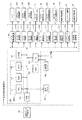
次に、上記立体造形装置の制御部の概要について図5を参照して説明する。図5は同制御部のブロック図である。 Next, the outline | summary of the control part of the said three-dimensional modeling apparatus is demonstrated with reference to FIG. FIG. 5 is a block diagram of the control unit.
制御部500は、この立体造形装置全体の制御を司るCPU501と、CPU501に本発明に係わる制御を含む立体造形動作の制御を実行させるためのプログラムを含むプログラム、その他の固定データを格納するROM502と、造形データ等を一時格納するRAM503とを含む主制御部500Aを備えている。
The
制御部500は、装置の電源が遮断されている間もデータを保持するための不揮発性メモリ(NVRAM)504を備えている。また、制御部500は、画像データに対する各種信号処理等を行う画像処理やその他装置全体を制御するための入出力信号を処理するASIC505を備えている。
The
制御部500は、外部の造形データ作成装置600から造形データを受信するときに使用するデータ及び信号の送受を行うためのI/F506を備えている。なお、造形データ作成装置600は、最終形態の造形物を各造形層にスライスした造形データを作成する装置であり、パーソナルコンピュータ等の情報処理装置で構成されている。
The
制御部500は、各種センサの検知信号を取り込むためのI/O507を備えている。
The
制御部500は、液体吐出ユニット50のヘッド52を駆動制御するヘッド駆動制御部508を備えている。
The
制御部500は、液体吐出ユニット50のキャリッジ51をX方向(主走査方向)に移動させるX方向走査機構550を構成するモータを駆動するモータ駆動部510と、造形ユニット5をY方向(副走査方向)に移動させるY方向走査機構552を構成するモータを駆動するモータ駆動部512を備えている。
The
制御部500は、液体吐出ユニット50のキャリッジ51をZ方向に移動(昇降)させるZ方向昇降機構551を構成するモータを駆動するモータ駆動部511を備えている。なお、矢印Z方向への昇降は造形ユニット5全体を昇降させる構成とすることもできる。
The
制御部500は、供給ステージ23を昇降させるモータ27を駆動するモータ駆動部513と、造形ステージ24を昇降させるモータ28を駆動するモータ駆動部514を備えている。
The
制御部500は、平坦化ローラ12を移動させる往復移動機構25のモータ553を駆動するモータ駆動部515と、平坦化ローラ12を回転駆動するモータ26を駆動する516を備えている。
The
制御部500は、供給槽21に粉体20を供給する粉体供給装置554を駆動する供給系駆動部517と、液体吐出ユニット50のメンテナンス機構61を駆動するメンテナンス駆動部518を備えている。
The
制御部500は、粉体後供給部80から粉体20の供給を行わせる後供給駆動部519を備えている。
The
制御部500のI/O507には、装置の環境条件としての温度及び湿度を検出する温湿度センサ560などの検知信号やその他のセンサ類の検知信号が入力される。
The I /
制御部500には、この装置に必要な情報の入力及び表示を行うための操作パネル522が接続されている。
An
なお、造形データ作成装置600と立体造形装置(粉体積層造形装置)601によって造形装置が構成される。
The modeling apparatus is configured by the modeling
次に、本発明の第1実施形態における制御部による粉体層の形成動作の制御について図6を参照して説明する。図6は同説明に供する模式的説明図である。 Next, control of the powder layer forming operation by the control unit according to the first embodiment of the present invention will be described with reference to FIG. FIG. 6 is a schematic explanatory diagram for explaining the same.
図6(a)に示すように、造形槽22の造形ステージ24上に、1又は複数層の造形層30が形成されているものとする。
As shown in FIG. 6A, it is assumed that one or more modeling layers 30 are formed on the
そこで、最上層の造形層30上に次の粉体層31を形成するときには、図6(b)に示すように、供給槽21の供給ステージ23をZ1方向に移動量z1分上昇させ、造形槽22の造形ステージ24をZ2方向に移動量z2分下降させる。
Therefore, when the
このとき、移動量z1、z2は粉体層31の厚みΔtよりも大きな値であり、移動量z2≧z1としている。これにより、供給槽21から粉体20を造形槽22に供給するとき供給される粉体20をすべて造形槽22内に収容することができる。
At this time, the movement amounts z1 and z2 are larger than the thickness Δt of the
そこで、図6(c)に示すように、平坦化ローラ12を、供給槽21側から一方の方向であるY2方向(往路方向とする。)に移動させて、粉体20を造形槽22へと移送供給する(粉体供給)。
Therefore, as shown in FIG. 6C, the flattening
次いで、図6(d)に示すように、供給槽21の供給ステージ23をZ2方向に移動量z3分下降させ、造形槽22の造形ステージ24をZ1方向に移動量z4分上昇させる。これにより、造形槽22の造形ステージ24上の粉体20が造形槽22の開口部から上方に盛り上がった状態になる。
Next, as shown in FIG. 6D, the
このときの造形ステージ24の移動量z4は、造形槽22の前回の粉体層31の表面(粉体面)の表面と平坦化ローラ12の下部(下方接線部)との間隔が粉体層31の厚みΔt1となるように設定する。粉体層31の厚みΔt1(積層ピッチ)は、数十〜100μm程度であることが好ましい。
The moving amount z4 of the
そこで、図6(e)に示すように、平坦化ローラ12をY1方向(復路方向とする。)に移動させることで、造形ステージ24の造形層30上で所定の厚さΔt1になる粉体層31が形成される。このとき、粉体層31の形成に使用されなかった未使用の粉体20は供給槽21に戻される。
Therefore, as shown in FIG. 6E, the powder having a predetermined thickness Δt1 on the
粉体層31を形成後、平坦化ローラ12は、図6(f)に示すように、更にY1方向に移動されて初期位置(原点位置)に戻される(復帰される)。その後、ヘッド52から造形液10の液滴を吐出して、次の粉体層31に所要形状の造形層30を積層形成する(造形)動作に移行する。
After the
なお、造形層30は、例えば、ヘッド52から吐出された造形液10が粉体20と混合されることで、粉体20に含まれる接着剤が溶解し、溶解した接着剤同士が結合して粉体20が結合されることで形成される。
The
次いで、上述した一方向に平坦化ローラ12を移動して造形槽22に粉体を移送供給し、他方向に平坦化ローラ12を移動して粉体の平坦化による粉体層31の形成を行い、ヘッド52による造形液の吐出して造形層30を形成する。このとき、新たな造形層30とその下層の造形層30とは一体化して三次元形状造形物の一部を構成する。
Next, the flattening
以後、粉体の供給・平坦化よる粉体層31を形成する工程、ヘッド52による造形液吐出工程を必要な回数繰り返すことによって、三次元形状造形物(立体造形物)を完成させる。
Thereafter, the step of forming the
このように、平坦化手段の往路移動(一方向への移動)で供給槽から造形槽に粉体を供給し、続いて、平坦化手段の復路移動(他方向への移動)で粉体層の形成と未使用粉体の供給槽への回収を行う。 In this way, the powder is supplied from the supply tank to the modeling tank by the forward movement of the flattening means (moving in one direction), and then the powder layer by the backward movement of the flattening means (moving in the other direction). And recovery of unused powder to the supply tank.
これにより、粉体層の形成に使用されなった未使用粉体はそのまま造形槽に戻されるので、品質の低下が抑制される。 As a result, the unused powder that has not been used for forming the powder layer is returned to the modeling tank as it is, so that deterioration in quality is suppressed.
また、供給槽及び造形槽外に未使用の粉体を排出することがないので、余剰な粉体を収容する余剰粉体受け手段、余剰粉体受け手段から粉体を回収して再度供給槽に戻すための回収機構を設ける必要がなく、装置の大型化を抑制できる。 In addition, since unused powder is not discharged outside the supply tank and the modeling tank, surplus powder receiving means for storing surplus powder, and the powder is recovered from the surplus powder receiving means and supplied again. There is no need to provide a recovery mechanism for returning to the apparatus, and an increase in the size of the apparatus can be suppressed.
次に、本発明の第2実施形態について図7を参照して説明する。図7は同実施形態における制御部による粉体層の形成動作の制御の説明に供する模式的説明図である。 Next, a second embodiment of the present invention will be described with reference to FIG. FIG. 7 is a schematic explanatory diagram for explaining the control of the powder layer forming operation by the control unit in the embodiment.
まず、図7(a)に示すように、供給槽21の供給ステージ23をZ1方向に移動量z1分上昇させ、造形槽22の造形ステージ24をZ2方向に移動量z2分下降させた後、平坦化ローラ12のY2方向への移動を開始する。
First, as shown in FIG. 7A, after the
そして、図7(b)に示すように、平坦化ローラ12のY2方向への移動によって供給槽21側から造形槽22側に粉体20を移送供給する(粉体供給)。
Then, as shown in FIG. 7B, the
次いで、図7(c)に示すように、供給槽21の供給ステージ23をZ2方向に移動量z3分下降させ、造形槽22の造形ステージ24をZ1方向に移動量z4分上昇させる。
Next, as shown in FIG. 7C, the
そして、平坦化ローラ12の矢印方向への回転駆動を開始し、平坦化ローラ12のY1方向への移動を開始する。
Then, rotational driving of the flattening
これにより、図7(d)に示すように、平坦化ローラ12は矢印方向に回転しながらY1方向に移動して、造形ステージ24の造形層30上で所定の厚さΔt1になる粉体層31が形成される。このとき、粉体層31の形成に使用されなかった未使用の粉体20は供給槽21に戻される。
As a result, as shown in FIG. 7D, the flattening
そして、図7(e)に示すように、厚さΔtの粉体層31を形成後、平坦化ローラ12が造形槽22を通過したとき、平坦化ローラ12の回転駆動を停止する。その後、更に平坦化ローラ12をY1方向に移動させて、図7(f)に示すように平坦化ローラ12を初期位置(原点位置)まで戻す。
Then, as shown in FIG. 7 (e), after the
その後、ヘッド52から造形液10を吐出して、次の粉体層31に所要形状の造形層30を積層形成する(造形)動作に移行すること、粉体層31の形成と造形層30の造形を繰り返して立体造形物を形成することは、前記第1実施形態と同様である。
Thereafter, the
本実施形態では、平坦化ローラ12を復路移動させて平坦化による粉体層31の形成を行うとき、造形槽22上を通過するときには平坦化ローラ12を矢印方向に回転させ、造形槽22を通過したときには平坦化ローラ12の回転駆動を停止している。
In the present embodiment, when the flattening
このように、平坦化ローラ12を回転させながら移動することで、高平面度な粉体層31を形成できる。そして、粉体層31を形成しているとき以外(造形テーブル24上を通過しているとき以外)は、平坦化ローラ12の回転駆動を停止することで、騒音の発生を少なくし、省電力を図れる。
Thus, the
また、供給槽21から造形槽22に対して1層分の粉体層31を形成するために必要な量に対して多量の粉体20を移送供給している。これにより、平坦化ローラ12のY2方向への移動、Y2方向への移動後の供給槽21及び造形槽22の平面度、平坦化ローラ12のY1方向への移動後の供給槽21の平面度が、粉体層31の平面度に及ぼす影響は小さく、造形物品質には影響がない。
Further, a large amount of the
次に、本発明の第3実施形態について図8を参照して説明する。図8は同実施形態の説明に供する模式的説明図である。 Next, a third embodiment of the present invention will be described with reference to FIG. FIG. 8 is a schematic explanatory diagram for explaining the embodiment.
本実施形態では、平坦化ローラ12がY2方向に移動するとき、つまり、供給槽21から造形槽22に粉体20を移送供給するときに、平坦化ローラ12の移動方向前方側に、平坦化ローラ12にとともに移動するブレード110を配置している。ブレード31には振動発生手段としての振動子111を備えている。
In the present embodiment, when the flattening
振動子111は、前記実施形態で説明した制御部500に備えた振動駆動部530を介して主制御部500Aで駆動制御される。なお、制御部500のその他の構成は前記第1実施形態で説明した同様である。
The
次に、本実施形態における制御部による粉体層の形成動作の制御の説明について図9を参照して説明する。図9は同説明に供する模式的説明図である。 Next, description will be given of the control of the operation of forming the powder layer by the control unit in the present embodiment with reference to FIG. FIG. 9 is a schematic explanatory view for explaining the same.
まず、図9(a)に示すように、供給槽21の供給ステージ23をZ1方向に移動量z1分上昇させ、造形槽22の造形ステージ24をZ2方向に移動量z2分下降させる。その後、振動子111を駆動してブレード110を振動させた状態で、ブレード111とともに平坦化ローラ12のY2方向への移動を開始する。
First, as shown in FIG. 9A, the
そして、図9(b)に示すように、ブレード110及び平坦化ローラ12のY2方向への移動によって供給槽21側から造形槽22側に粉体20を移送供給する(粉体供給)。このとき、ブレッド110によって粉体20がタッピングされる。ブレード110は、造形槽22を通過したときに振動が停止される。
Then, as shown in FIG. 9B, the
次いで、図9(c)に示すように、供給槽21の供給ステージ23をZ2方向に移動量z3分下降させ、造形槽22の造形ステージ24をZ1方向に移動量z4分上昇させる。
Next, as shown in FIG. 9C, the
そして、平坦化ローラ12の矢印方向への回転駆動を開始し、平坦化ローラ12のY1方向への移動を開始する。
Then, rotational driving of the flattening
これにより、図9(d)に示すように、平坦化ローラ12は矢印方向に回転しながらY1方向に移動して、造形ステージ24の造形層30上で所定の厚さΔt1になる粉体層31が形成される。このとき、粉体層31の形成に使用されなかった未使用の粉体20は供給槽21に戻される。
As a result, as shown in FIG. 9D, the flattening
そして、図9(e)に示すように、厚さΔtの粉体層31を形成後、平坦化ローラ12が造形槽22を通過したとき、平坦化ローラ12の回転駆動を停止する。その後、更に平坦化ローラ12をY1方向に移動させて、図9(f)に示すように平坦化ローラ12を初期位置(原点位置)まで戻す。
Then, as shown in FIG. 9 (e), after the
その後、ヘッド52から造形液10を吐出して、次の粉体層31に所要形状の造形層30を積層形成する(造形)動作に移行すること、粉体層31の形成と造形層30の造形を繰り返して立体造形物を形成することは、前記第1実施形態と同様である。
Thereafter, the
このように、振動するブレード110(振動付与手段)で粉体20をタッピングしながら移送供給することで、高密度な状態で造形槽22内に粉体が供給される。これにより、高密度、高平面度な粉体層31を形成することができる。
Thus, the
また、供給槽21から造形槽22に対して1層分の粉体層31を形成するために必要な量に対して多量の粉体20を移送供給しているので、ブレード110と前層の造形層30とが粉体層31の積層ピッチより大きく離間した状態となる。
In addition, since a large amount of the
これにより、ブレード110の振動により粉体20をタッピングしながら造形槽22に供給するとき、振動のエネルギーを大きくしても、既存の造形層30に対する悪影響(ズレや破損)を生じることなく、高密度な粉体層31を形成することができる。
As a result, when the
次に、本発明の第4実施形態について図10を参照して説明する。図10は同実施形態の説明に供する模式的説明図である。 Next, a fourth embodiment of the present invention will be described with reference to FIG. FIG. 10 is a schematic explanatory diagram for explaining the embodiment.
本実施形態では、平坦化ローラ12の移動方向において、造形槽22と反対側の供給槽21の端部における粉体20の表面のZ方向位置を検知する第1変位検知手段41を備えている。同様に、平坦化ローラ12の移動方向において、供給槽21と反対側の造形槽供22の端部における粉体20の表面のZ方向位置を検知する第2変位検知手段42を備えている。
In the present embodiment, the first displacement detection means 41 that detects the Z-direction position of the surface of the
第1変位検知手段41、第2変位検知手段42の各検知信号は、制御部500のI/O507に入力される。制御部500は、第1変位検知手段41で検知した粉体20の表面のZ方向位置は不揮発性メモリ505などに格納保持される。
The detection signals of the first displacement detection means 41 and the second displacement detection means 42 are input to the I /
次に、本実施形態における制御部による造形制御について図11及び図12を参照して説明する。図11は同制御の説明に供するフロー図、図12は図10のC部に相当する粉体層の形成状態の説明に供する説明図である。 Next, modeling control by the control unit in the present embodiment will be described with reference to FIGS. 11 and 12. FIG. 11 is a flowchart for explaining the control, and FIG. 12 is an explanatory diagram for explaining the formation state of the powder layer corresponding to part C of FIG.
まず、図11を参照して、前記第3実施形態と同様にして、粉体層31の形成(リコート)を行う。
First, referring to FIG. 11, the
そして、第1変位検知手段41で供給槽22の粉体層形成後の粉体表面のZ方向位置を検知し、格納保持された前回の粉体供給時の粉体表面のZ方向位置と比較し、前回からの変化量(差)が予め設定した閾値を越えているか否かを判別する。
Then, the first displacement detection means 41 detects the Z-direction position of the powder surface after the powder layer is formed in the
ここで、前回からの変化量(差)が閾値を越えているときには、次回リコート時の供給ステージ23と造形ステージ24の移動量z1、z2を変更し、格納保持しているZ方向位置と検知したZ方向位置の差がなくなるように補正する。
Here, when the amount of change (difference) from the previous time exceeds the threshold, the movement amounts z1 and z2 of the
その後、また、前回からの変化量(差)が閾値を越えていないときはそのまま、第2変位検知手段42によって粉体層31の端部を検知して、粉体層31の形成不良が発生していないか否かを判別する。
After that, when the amount of change (difference) from the previous time does not exceed the threshold value, the end of the
すなわち、第2変位検知手段42によって粉体層31の端部を検知した結果、例えば図12(a)に示す状態であるときは正常とし、図12(b)に示すようにだれているときには不良とする。
That is, as a result of detecting the end portion of the
ここで、粉体層31の形成不良が発生しているときには、再度粉体層31の形成を行う。
Here, when the formation failure of the
そして、正常な粉体層31が形成されたときに、液体を吐出して造形層30を形成する。
Then, when the
これにより、造形動作を繰返し、粉体層形成(リコート)、液体吐出を実施しても確実に薄層形成不良を防止することができる。したがって、造形物形状や雰囲気環境に起因して生じる液体吐出後の造形層30の収縮量変化や、粉体20のかさ密度変化が生じても、継続して安定的に粉体層の形成と造形層の造形を繰り返すことができる。
Thereby, even if modeling operation is repeated and powder layer formation (recoating) and liquid discharge are implemented, the thin layer formation defect can be prevented reliably. Therefore, even if the shrinkage amount change of the
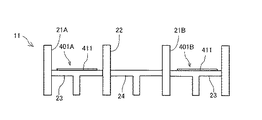
次に、本発明の第5実施形態に係る立体造形装置の一例の概要について図13ないし図15を参照して説明する。図13は同立体造形装置の概略平面説明図、図14は同じく概略側面説明図、図15は同じく造形部の断面説明図である。 Next, an outline of an example of the three-dimensional modeling apparatus according to the fifth embodiment of the present invention will be described with reference to FIGS. FIG. 13 is an explanatory schematic plan view of the three-dimensional modeling apparatus, FIG. 14 is an explanatory schematic side view, and FIG. 15 is an explanatory sectional view of the modeling unit.
この装置では、粉体槽11として、造形槽22と、平坦化ローラ12の移動方向において造形槽22の両側に配置され、粉体20を収容する2つの供給槽21A、21B(以下、区別しないときは「供給槽21」という。他の部材も同様)を備えている。
In this apparatus, as the
そして、平坦化ローラ12は、供給槽21A、造形層22及び供給槽21B上を往復移動可能に配置されている。平坦化ローラ12は、供給槽21A又は21Bから造形槽22に粉体20を移送し、造形槽22に供給された粉体20を平坦化して粉体層31を形成する平坦化手段である。
And the flattening
次に、本実施形態における供給槽内の攪拌手段について図16及び図17を参照して説明する。図16は同実施形態における粉体槽部分の側面説明図、図17は同じく平面説明図である。 Next, the stirring means in the supply tank in this embodiment is demonstrated with reference to FIG.16 and FIG.17. FIG. 16 is an explanatory side view of a powder tank portion in the same embodiment, and FIG. 17 is an explanatory plan view of the same.
本実施形態では、供給槽21Aの供給ステージ23上には、攪拌手段401Aとしての回転盤411が回転可能に配置されている。同様に、供給槽21Bの供給ステージ23上には、攪拌手段401Bとしての回転盤411が回転可能に配置されている。
In the present embodiment, on the
回転盤411は、正逆両方向に回転可能であり、回転速度も変更可能である。
The
なお、その他の構成は、前記第1実施形態で説明した装置と同様である。 Other configurations are the same as those of the apparatus described in the first embodiment.
次に、この装置における制御部の概要について図18を参照して説明する。図18は同制御部のブロック説明図である。 Next, an outline of a control unit in this apparatus will be described with reference to FIG. FIG. 18 is a block diagram of the control unit.
制御部500は、供給槽21A、21Bの各造形ステージ23を昇降させるモータ27A、27Bを個別に駆動するモータ駆動部513と、攪拌手段401A、401Bの回転盤411を回転させるモータ542A、542Bを個別に駆動するモータ駆動部541とを備えている。
The
なお、その他の構成は、前記第1実施形態で制御部と同様である。 The other configuration is the same as that of the control unit in the first embodiment.
次に、本実施形態における制御部による粉体層の形成動作の制御について図19及び図20を参照して説明する。図19は同制御の説明に供するフロー図、図20は同じく説明図である。 Next, control of the powder layer forming operation by the control unit in the present embodiment will be described with reference to FIGS. 19 and 20. FIG. 19 is a flowchart for explaining the control, and FIG. 20 is an explanatory diagram.
ここでは、供給槽21A、21Bのいずれか一方から造形槽22に粉体20を供給するとき、他方は未使用の粉体20を受けて収容する回収槽として機能させる。そこで、供給側と回収側を区別するときには、平坦化ローラ12で造形槽22に粉体20を供給する側を「供給側の供給槽21」と称し、未使用の粉体20を回収している側を「回収側の供給槽21」と称する。
Here, when the
図19を参照して、供給槽21Aの供給ステージ23と供給槽21Bの供給ステージ23の高さを、供給側の供給槽21に合わせる。
Referring to FIG. 19, the heights of the
すなわち、供給側の供給槽21から供給される粉体20の供給量と回収側の供給槽21に収容される粉体20の回収量は、粉体層31を1層形成するための粉体量分少なくなる。
That is, the supply amount of the
そこで、供給槽21Aの供給ステージ23と供給槽21Bの供給ステージ23の高さを、供給側の供給槽21に合わせておくことで、回収側の供給槽21の容積が当該粉体層31を形成するときに生じる未使用の粉体20で満たされることはない。これにより、回収側の供給槽21の上部をヘッド52が通過するときにノズル面が粉体20と接触して吐出不良を生じるおそれがなくなる。
Therefore, by adjusting the height of the
その後、造形槽22の造形ステージ24を上昇させないで、供給側の供給槽21から1層分以上の粉体20を回収側の供給槽21に移送する(これを「捨てリコート」という。)。これは、詳細は後述するが、供給側と回収側を入れ替えるときに、次の供給側の供給槽21から供給される粉体20の量を一定に保つために行っている。
Thereafter, the
そして、所定厚みの粉体層31を形成する。
Then, a
ここでは、供給側の供給槽21の供給ステージ23を所要量上昇させ、造形槽22の造形ステージ24を所定量(粉体層31の厚みΔt相当分)下降させる。そして、平坦化ローラ12をY方向に移動して、供給側の供給槽21から造形槽22に粉体20を供給し、所定厚みΔtの粉体層31を形成する。このとき、平坦化ローラ12は回収側の供給槽21の上方まで移動して、未使用の粉体20は回収側の供給槽21に収容されて回収される。
Here, the
その後、回収側の供給槽21の攪拌手段401としての回転盤411を正逆両方向に往復回転させて収容された粉体20を攪拌して均す。
After that, the
そして、供給側の供給槽21の供給ステージ23が所定の高さまで到達した(上昇した)か否かを判別する。
Then, it is determined whether or not the
ここで、供給側の供給槽21の供給ステージ23が所定の高さまで到達していないときには、供給側の供給槽21の粉体20を使用して粉体層31の形成を行い、回収側の供給槽21に収容した粉体20を攪拌して均す動作を繰り返す。
Here, when the
これに対し、供給側の供給槽21の供給ステージ23が所定の高さまで到達したときには、現在の回収側の供給槽21が供給槽21Bであるか否かを判別する。
In contrast, when the
ここで、現在の回収側の供給槽21が供給槽21Bであるときには、平坦化ローラ12を供給槽21Bの初期位置に移動する。
Here, when the
そして、供給槽21Bから粉体20がはみ出るまで供給ステージ23Bを上昇させる。
Then, the supply stage 23B is raised until the
その後、供給槽21Bを供給側の供給槽21とし、供給槽21Aを回収側の供給槽21とする入れ替え設定を行う。
Thereafter, the
これに対し、現在の回収側の供給槽21が供給槽21Bでないときには、すなわち、回収側の供給槽21が供給槽21Aであるときには、平坦化ローラ12を供給槽21Aの初期位置に移動する。
In contrast, when the current collection-
そして、供給槽21Aから粉体20がはみ出るまで供給ステージ23Bを上昇させる。
Then, the supply stage 23B is raised until the
その後、供給槽21Aを供給側の供給槽21とし、供給槽21Bを回収側の供給槽21とする入れ替え設定を行う。
Thereafter, the
このように、攪拌手段を有する2つの供給槽を備えて、粉体層に形成に使用されなかった未使用の粉体を収容して攪拌することで、収容した粉体の均しを行っている。 In this way, two supply tanks having stirring means are provided, and unused powder that has not been used for forming the powder layer is contained and stirred, so that the contained powder is leveled. Yes.
例えば、図20(a)に示すように、平坦化ローラ12で粉体層31を形成するときに粉体層31の形成に使用されなかった未使用の粉体20は、例えば回収側の供給槽21が供給槽21Bであるとき、供給槽21Bに収容される。
For example, as shown in FIG. 20A,
そこで、攪拌手段401Bとしての回転盤411を回転して、図20(b)に示すように、供給槽21Bに収容された粉体20を均している。
Therefore, the
すなわち、供給側の供給槽21から供給された粉体20のうちの粉体層31の形成に使用されなかった粉体20は回収側の供給槽21まで移送される。このとき、造形槽22を通過した未使用の粉体20は、回収側の供給槽21の造形槽22側の壁面を伝って落下することになる。
That is, of the
そのため、回収側の供給槽21の造形槽22側の壁面に偏って堆積する。堆積された粉体20は、粉体材料由来の安息角を超えない限り崩れ落ちないため、そのままでは粉体20の偏った領域での堆積が進行することになる。その結果、供給槽21に収容余力があるにもかかわらず、供給槽21の開口から上部に部分的にはみ出してしまう。
For this reason, the deposits are concentrated on the wall surface of the recovery-
また、供給槽21で粉体20の堆積に偏りが生じることで、回収側の供給槽21と供給側の供給槽21とを交代させたときに、交代直後の供給量を一定にするのが難しくなる。
Further, since the accumulation of the
そこで、供給槽21の供給ステージ23に撹拌手段401を設けて、粉体20を回収している間に回収側の供給槽21内を撹拌することで、回収された粉体20が回収側の供給槽21の開口からはみ出てしまうことを防止する。また、回収側の供給槽21内の粉体20を撹拌することで、収容された粉体の密度むらを低減して再供給することになる粉体の品質低下を低減することができる。
In view of this, the agitation means 401 is provided in the
ここで、攪拌手段401としての回転盤411は、少なくとも粉体層31を1層積層する間回転させる。
Here, the
これにより、堆積された粉体20が崩され、ある程度平らに均される。毎回同じ機構で供給ステージ23の回転盤411が回転されるため、回収側となる供給槽21が入れ替わっても、粉体の撹拌度合いは一定である。したがって、供給される粉体20の状態(量、密度)も一定にすることができ、造形物の品質を一定に保つことができる。
Thereby, the deposited
また、供給側の供給槽21と回収側の供給槽21を入れ替えるとき、上述したように、造形槽22の造形ステージ24を上昇させないで、入れ替え後に供給側となる供給槽21から1層分以上の粉体20を入れ替え後に回収側となる供給槽21に移送する捨てリコートを行う。
Further, when the
つまり、撹拌手段によって撹拌しても回収側の供給槽21に収容された粉体20の表面の平坦性は十分でない。一方、粉体20の供給量を一定にするためには、供給槽21の上部で粉体20が擦り切り状態になっていることが好ましい。
That is, even if stirring is performed by the stirring means, the flatness of the surface of the
そこで、造形ステージ24の高さを変えずに、次に供給側となる供給槽21の供給ステージ23を上昇させ、平坦化ローラ12で擦り切るように捨てリコートを行う。これにより、造形再開時に粉体20の供給量が変化することはなく、常に一定量の供給量を搬送することができる。
Therefore, without changing the height of the
そして、捨てリコート中、又は、捨てリコート終了後に、次に回収側となる供給槽21の供給ステージ23の高さを次に供給側となる供給槽21の供給ステージ23の高さに合わせ、その後、粉体層31の形成、造形層10の造形を再開する。
Then, during the disposal recoating or after the disposal recoating, the height of the
これを造形終了まで繰り返すことによって、常に一定の供給量を確保しつつ、使用した粉体を再利用することができる。 By repeating this until the end of modeling, the used powder can be reused while always ensuring a constant supply amount.
次に、本発明の第6実施形態について図21及び図22を参照して説明する。図21は同実施形態における粉体槽の模式的側面説明図、図22は同じく平面説明図である。 Next, a sixth embodiment of the present invention will be described with reference to FIGS. FIG. 21 is a schematic side view of the powder tank in the same embodiment, and FIG. 22 is a plan view of the same.
攪拌手段401として、供給ステージ23に対して垂直方向に立つ複数本の円柱状部材413を備えている。円柱状部材413の周面はスクリュー形状に形成され、円柱状部材413を回転させることで、供給ステージ23の上昇、下降動作も同時に行うことができる。
As the stirring means 401, a plurality of
次に、本実施形態の作用について図23も参照して説明する。図23は同作用説明に供する要部側面説明図である。 Next, the operation of this embodiment will be described with reference to FIG. FIG. 23 is an explanatory side view of the main part for explaining the operation.
図23(a)に示すように、粉体層31の形成に使用されなかった未使用の粉体20は、回収側の供給槽21(ここでは、供給槽21Bとする。)に排出されて収容される。そこで、攪拌手段401としての円柱状部材413が少なくとも積層回数1回以上の間隔で正逆方向に回転される。
As shown in FIG. 23A,
これにより、供給ステージ23が上下に動作する(昇降する)とともに、円柱状部材413の側面に位置する粉体20が回転によって動くことで、円柱状部材413の近傍にある堆積された粉体20が崩され、図23(b)に示すように、粉体20はある程度平らに均される。
Accordingly, the
このとき、毎回同じ攪拌手段401で動作するため、回収側の供給槽21が入れ替わっても粉体20の撹拌度合いは一定である。
At this time, since the same stirring means 401 is operated every time, the degree of stirring of the
したがって、供給される粉体20の状態(量、密度)も一定にすることができ、造形品質を一定に保つことができる。
Therefore, the state (amount and density) of the supplied
次に、本発明の第7実施形態について図24及び図25を参照して説明する。図24は同実施形態における粉体槽の模式的側面説明図、図25は同じく平面説明図である。 Next, a seventh embodiment of the present invention will be described with reference to FIGS. FIG. 24 is a schematic side view of the powder tank in the same embodiment, and FIG. 25 is a plan view of the same.
攪拌手段401として、供給ステージ23の内部に配置された振動機構部414を備えている。振動機構部414による振動方向は、供給ステージ23の面内方向及び面直方向のいずれでもよい。
As the agitation means 401, a
次に、本実施形態の作用について図26も参照して説明する。図26は同作用説明に供する要部側面説明図である。 Next, the operation of this embodiment will be described with reference to FIG. FIG. 26 is an explanatory side view of the main part for explaining the operation.
図26(a)に示すように、粉体層31の形成に使用されなかった未使用の粉体20は、回収側の供給槽21(ここでは、供給槽21Bとする。)に排出されて収容される。そこで、攪拌手段401としての振動機構部414によって振動を与える。
As shown in FIG. 26 (a),
これにより、供給ステージ23上に堆積された粉体20が崩され、ある程度平らに均される。
As a result, the
このとき、毎回同じ攪拌手段401で動作するため、回収側の供給槽21が入れ替わっても粉体20の撹拌度合いは一定である。
At this time, since the same stirring means 401 is operated every time, the degree of stirring of the
したがって、供給される粉体20の状態(量、密度)も一定にすることができ、造形品質を一定に保つことができる。
Therefore, the state (amount and density) of the supplied
次に、供給側の供給槽と回収側の供給槽の入れ替えについて図27を参照して説明する。図27は同説明に供する模式的説明図である。 Next, replacement of the supply tank on the supply side and the supply tank on the recovery side will be described with reference to FIG. FIG. 27 is a schematic explanatory view for the same explanation.
図27(a)に示すように、供給側の供給槽21(ここでは、供給槽21Aとする。)の供給ステージ23が所定の高さまで到達すると、平坦化ローラ12は、Y2方向に、回収側の供給槽21(ここでは、供給槽21Bとする。)から供給するときの初期位置に移動する。
As shown in FIG. 27A, when the
この場合、供給槽21Aから造形槽22への粉体供給が終了した段階で、そのまま平坦化ローラ12は供給槽21Bの初期位置まで移動する。
In this case, at the stage where the powder supply from the
その後、図27(b)に示すように、供給槽21Bの供給ステージ23を供給槽21Bの開口から粉体20が完全にはみ出るまで供給ステージ23を上昇させ、供給槽21Aの供給ステージ23を供給槽21Bの供給ステージ23と同じ高さまで下降させる。
Thereafter, as shown in FIG. 27B, the
そして、平坦化ローラ12を、Y1方向に、供給槽21B側から供給槽21A側に移動させて、図27(c)に示すように、はみ出している粉体20を供給槽21Aに移送する。
Then, the flattening
すなわち、前述したように、回収側の供給槽21であった供給槽21Bに収容されている粉体20は、完全には均されていないため、粉体20を完全に均すために捨てリコートを一層分行っている。
That is, as described above, the
このとき、平坦化ローラ12の移動速度は、粉体層31を形成するときの移動速度以下とすることが好ましい。つまり、造形槽22の最表面の粉体層31には造形層30が形成された状態にある。そこで、平坦化ローラ12の移動速度を、粉体層31を形成するときの移動速度以下とすることで、粉体20を移送するときに、造形層30の位置ずれが生じることを防止し、造形物の状態を維持する。
At this time, the moving speed of the flattening
上述した捨てリコートを行うことで、供給槽21B内の粉体20は完全に均されるため、その後の粉体層31の形成を行うときに供給される粉体量のばらつきを低減できる。
By performing the above-described discard recoating, the
1 造形部
5 造形ユニット
10 造形液
12 平坦化ローラ(平坦化手段、回転体)
20 粉体
21、21A、21B 供給槽
22 造形槽
23 供給ステージ
24 造形ステージ
30 造形層(層状造形物)
31 粉体層(層状の粉体)
50 液体吐出ユニット
51 キャリッジ
52 液体吐出ヘッド(造形液用)
401 攪拌手段
DESCRIPTION OF
20
31 Powder layer (layered powder)
50
401 Stirring means
Claims (10)
前記粉体を収容する供給槽と、
前記供給槽及び前記造形槽の上方を往復移動可能に配置され、前記粉体を移送し、前記造形槽に供給された前記粉体を平坦化して前記粉体層を形成する平坦化手段と、
前記粉体の移送と前記粉体層の形成を制御する手段と、を備え、
前記制御する手段は、
前記平坦化手段の一方向への移動で、前記供給槽から前記造形槽に対して前記粉体を移送して供給し、
前記平坦化手段の他方向への移動で、前記粉体層を形成し、前記粉体層の形成に使用されなかった前記粉体を前記造形槽から前記供給槽に戻し移送する
制御を行う
ことを特徴とする立体造形装置。 A modeling tank in which a powder layer in which powder is layered is formed, and a layered shaped article in which the powder of the powder layer is combined in a required shape, and
A supply tank containing the powder;
A flattening means arranged so as to be reciprocally movable above the supply tank and the modeling tank, transferring the powder, and flattening the powder supplied to the modeling tank to form the powder layer;
Means for controlling the transfer of the powder and the formation of the powder layer,
The means for controlling is
In one direction of movement of the flattening means, the powder is transferred from the supply tank to the modeling tank and supplied,
The powder layer is formed by movement in the other direction of the flattening means, and the powder that has not been used to form the powder layer is controlled to be transferred back from the modeling tank to the supply tank. 3D modeling apparatus characterized by
ことを特徴とする請求項1に記載の立体造形装置。 The three-dimensional modeling apparatus according to claim 1, wherein the flattening means is a rotating member and is rotationally driven when moving in the other direction above the modeling tank.
前記振動を与える手段は、前記供給槽から前記造形槽に粉体を移送するときに前記粉体に振動を与える
ことを特徴とする請求項1又は2に記載の立体造形装置。 Above the supply tank and the modeling tank is disposed so as to be reciprocally movable, and includes means for applying vibration to the powder.
The three-dimensional modeling apparatus according to claim 1, wherein the vibration applying unit applies vibration to the powder when the powder is transferred from the supply tank to the modeling tank.
前記検知する手段の検知結果から次回の平坦化を行うときの条件を変更する制御をする
ことを特徴とする請求項1ないし3のいずれかに記載の立体造形装置。 Means for detecting the surface state of the powder in the modeling tank;
The three-dimensional modeling apparatus according to any one of claims 1 to 3, wherein control is performed to change a condition for performing the next flattening based on a detection result of the detecting means.
前記検知する手段の検知結果から前記粉体層の形成をやり直す制御をする
ことを特徴とする請求項1ないし3のいずれかに記載の立体造形装置。 Means for detecting the surface state of the powder in the modeling tank;
4. The three-dimensional modeling apparatus according to claim 1, wherein control is performed to redo the formation of the powder layer from the detection result of the detecting means. 5.
前記造形槽の両側に配置され、前記粉体を収容する2つの供給槽と、
前記供給槽及び前記造形槽の上方を往復移動可能に配置され、前記供給槽から前記造形槽に前記粉体を移送し、前記造形槽に供給された前記粉体を平坦化して前記粉体層を形成する平坦化手段と、を備え、
前記2つの供給槽の内の一方の供給槽から前記造形槽に前記粉体を供給するとき、他方の供給槽には前記粉体層の形成に使用されなかった前記粉体が排出されて収容され、
前記2つの供給槽には、収容された前記粉体を撹拌する撹拌手段を備えている
ことを特徴とする立体造形装置。 A modeling tank in which a powder layer in which powder is layered is formed, and a layered shaped article in which the powder of the powder layer is combined in a required shape, and
Two supply tanks arranged on both sides of the modeling tank and containing the powder;
The powder layer is disposed so as to be able to reciprocate above the supply tank and the modeling tank, transfers the powder from the supply tank to the modeling tank, and flattens the powder supplied to the modeling tank. And flattening means for forming,
When the powder is supplied to the modeling tank from one of the two supply tanks, the powder that has not been used for forming the powder layer is discharged and stored in the other supply tank. And
The three-dimensional modeling apparatus, wherein the two supply tanks are provided with stirring means for stirring the powder contained therein.
ことを特徴とする請求項6に記載の立体造形装置。 When the supply tank that supplies the powder to the modeling tank is switched from one supply tank to the other supply tank, the flattening means does not form the powder layer in the modeling tank. The three-dimensional modeling apparatus according to claim 6, wherein the powder is transferred from the other supply tank to the one supply tank and the powder surface of the other supply tank is leveled.
ことを特徴とする請求項7に記載の立体造形装置。 The movement speed of the flattening means when transferring the powder from the other supply tank to the one supply tank is slower than the movement speed when forming the powder layer in the modeling tank. The three-dimensional modeling apparatus according to claim 7.
前記攪拌手段は、前記供給ステージ上に配置された回転盤を有し、
前記回転盤は、少なくとも一層の前記粉体層を形成する間は回転する
ことを特徴とする請求項6ないし8のいずれかに記載の立体造形装置。 The supply tank has a supply stage that is arranged to be movable up and down and holds the powder.
The stirring means has a turntable disposed on the supply stage,
The three-dimensional modeling apparatus according to any one of claims 6 to 8, wherein the rotating disk rotates while forming at least one powder layer.
ことを特徴とする請求項9に記載の立体造形装置。 The three-dimensional modeling apparatus according to claim 9, wherein the rotating disk periodically repeats rotation in both forward and reverse directions.
Priority Applications (4)
| Application Number | Priority Date | Filing Date | Title |
|---|---|---|---|
| JP2015217143A JP2017087469A (en) | 2015-11-04 | 2015-11-04 | Apparatus for three-dimensional fabrication |
| EP20169133.4A EP3695925B1 (en) | 2015-11-04 | 2016-10-21 | Apparatus for fabricating three-dimensional object |
| US15/299,788 US10265769B2 (en) | 2015-11-04 | 2016-10-21 | Apparatus for fabricating three-dimensional object |
| EP16195144.7A EP3165304B1 (en) | 2015-11-04 | 2016-10-21 | Apparatus for fabricating three-dimensional object |
Applications Claiming Priority (1)
| Application Number | Priority Date | Filing Date | Title |
|---|---|---|---|
| JP2015217143A JP2017087469A (en) | 2015-11-04 | 2015-11-04 | Apparatus for three-dimensional fabrication |
Related Child Applications (1)
| Application Number | Title | Priority Date | Filing Date |
|---|---|---|---|
| JP2020020388A Division JP6699811B2 (en) | 2020-02-10 | 2020-02-10 | 3D modeling device |
Publications (1)
| Publication Number | Publication Date |
|---|---|
| JP2017087469A true JP2017087469A (en) | 2017-05-25 |
Family
ID=57189900
Family Applications (1)
| Application Number | Title | Priority Date | Filing Date |
|---|---|---|---|
| JP2015217143A Pending JP2017087469A (en) | 2015-11-04 | 2015-11-04 | Apparatus for three-dimensional fabrication |
Country Status (3)
| Country | Link |
|---|---|
| US (1) | US10265769B2 (en) |
| EP (2) | EP3165304B1 (en) |
| JP (1) | JP2017087469A (en) |
Cited By (4)
| Publication number | Priority date | Publication date | Assignee | Title |
|---|---|---|---|---|
| JP2019044263A (en) * | 2017-07-31 | 2019-03-22 | ゼネラル・エレクトリック・カンパニイ | Automatic powder compaction |
| WO2019159644A1 (en) * | 2018-02-16 | 2019-08-22 | 株式会社日立製作所 | Additive manufacturing apparatus |
| JP2020082487A (en) * | 2018-11-22 | 2020-06-04 | ローランドディー.ジー.株式会社 | Three-dimensional molding device |
| US11179777B2 (en) | 2017-05-11 | 2021-11-23 | Ricoh Company, Ltd. | Device for fabricating three-dimensional fabrication object and method of manufacturing three-dimensional fabrication object |
Families Citing this family (10)
| Publication number | Priority date | Publication date | Assignee | Title |
|---|---|---|---|---|
| KR101682087B1 (en) * | 2015-11-27 | 2016-12-02 | 한국기계연구원 | Apparatus and method for manufacturing three dimensional shapes using laser and powder |
| US10518478B2 (en) * | 2016-05-10 | 2019-12-31 | Hamilton Sundstrand Corporation | Additive manufacturing systems and methods |
| WO2017194144A1 (en) * | 2016-05-12 | 2017-11-16 | Hewlett-Packard Development Company, L.P. | Container for 3d printed objects and method of cooling and unpacking a manufactured object from a 3d printer using that container |
| WO2018022002A1 (en) | 2016-07-26 | 2018-02-01 | Hewlett-Packard Development Company, L.P. | Cooling of build material in 3d printing system |
| CN110461577B (en) * | 2017-04-21 | 2021-12-03 | 惠普发展公司,有限责任合伙企业 | Recoater movement |
| JP2020059227A (en) | 2018-10-11 | 2020-04-16 | 株式会社リコー | Manufacturing method and apparatus for three-dimensional modeling object |
| EP3718745A1 (en) * | 2019-04-02 | 2020-10-07 | Concept Laser GmbH | Apparatus for additively manufacturing a three-dimensional object |
| JP2021161492A (en) | 2020-03-31 | 2021-10-11 | 株式会社リコー | Molding table and molding apparatus |
| FR3123580B1 (en) * | 2021-06-03 | 2024-07-26 | Centre Techn Ind Mecanique | Methods and installation for additive manufacturing of three-dimensional metal parts |
| US20240157643A1 (en) * | 2022-11-11 | 2024-05-16 | General Electric Company | Build material escapement assembly and additive manufacturing systems including same |
Citations (3)
| Publication number | Priority date | Publication date | Assignee | Title |
|---|---|---|---|---|
| JP2003245981A (en) * | 2002-02-25 | 2003-09-02 | Matsushita Electric Works Ltd | Method and device for manufacturing three- dimensionally shaped article |
| JP2004143581A (en) * | 2002-08-27 | 2004-05-20 | Matsushita Electric Works Ltd | Manufacturing device of three-dimensionally shaped article |
| JP2007516342A (en) * | 2003-06-30 | 2007-06-21 | フェニックス システムズ | An apparatus for producing a thin powder layer by processing based on the action of a laser on the material, especially at high temperatures |
Family Cites Families (21)
| Publication number | Priority date | Publication date | Assignee | Title |
|---|---|---|---|---|
| US5387380A (en) * | 1989-12-08 | 1995-02-07 | Massachusetts Institute Of Technology | Three-dimensional printing techniques |
| US5252264A (en) * | 1991-11-08 | 1993-10-12 | Dtm Corporation | Apparatus and method for producing parts with multi-directional powder delivery |
| JP3551838B2 (en) | 1999-05-26 | 2004-08-11 | 松下電工株式会社 | Manufacturing method of three-dimensional shaped object |
| JP2005059324A (en) | 2003-08-08 | 2005-03-10 | Ricoh Co Ltd | Three-dimensional laminate shaping apparatus |
| US7296990B2 (en) | 2005-10-14 | 2007-11-20 | Hewlett-Packard Development Company, L.P. | Systems and methods of solid freeform fabrication with translating powder bins |
| JP4866145B2 (en) | 2006-05-17 | 2012-02-01 | 株式会社アスペクト | Powder sintering additive manufacturing apparatus and method of using the same |
| JP5332724B2 (en) * | 2009-02-26 | 2013-11-06 | ソニー株式会社 | Three-dimensional modeling apparatus and control method |
| WO2011001270A2 (en) * | 2009-07-03 | 2011-01-06 | Inspire AG für mechatronische Produktionssysteme und Fertigungstechnik | Device and method for the layered production of a three-dimensional object |
| EP2674283A3 (en) * | 2009-08-20 | 2014-05-07 | Matthias Fockele | Device for manufacturing moulded bodies by layered construction using a material powder |
| DE102010043166A1 (en) | 2010-10-29 | 2012-05-03 | Eos Gmbh Electro Optical Systems | Device for treating powder for a device for producing a three-dimensional object and device for producing a three-dimensional object |
| EP3597398A1 (en) | 2013-03-12 | 2020-01-22 | Orange Maker, LLC | 3d printing using spiral buildup |
| US9550207B2 (en) * | 2013-04-18 | 2017-01-24 | Arcam Ab | Method and apparatus for additive manufacturing |
| JP5740716B2 (en) | 2013-05-24 | 2015-06-24 | 株式会社シマブンコーポレーション | Manufacturing method of three-dimensional structure |
| US9505057B2 (en) | 2013-09-06 | 2016-11-29 | Arcam Ab | Powder distribution in additive manufacturing of three-dimensional articles |
| EP2851145A1 (en) * | 2013-09-18 | 2015-03-25 | Siemens Aktiengesellschaft | Device for layered generation of components by means of a generative production method, method and component |
| US20160332371A1 (en) | 2014-01-22 | 2016-11-17 | United Technologies Corporation | Additive manufacturing system and method of operation |
| JP6379684B2 (en) | 2014-06-02 | 2018-08-29 | 株式会社リコー | 3D modeling equipment |
| US9694542B2 (en) | 2014-09-12 | 2017-07-04 | Ricoh Company, Ltd. | Method and apparatus for molding three-dimensional object and molding data generation method for three-dimensional object |
| JP6481383B2 (en) | 2015-01-27 | 2019-03-13 | 株式会社リコー | 3D modeling apparatus, 3D modeling production method, program |
| US20160236422A1 (en) | 2015-02-13 | 2016-08-18 | Ricoh Company, Ltd. | Device and method for removing powder and apparatus for fabricating three-dimensional object |
| US10029440B2 (en) | 2015-02-19 | 2018-07-24 | Ricoh Company, Ltd. | Method and apparatus for fabricating three-dimensional object and recording medium |
-
2015
- 2015-11-04 JP JP2015217143A patent/JP2017087469A/en active Pending
-
2016
- 2016-10-21 EP EP16195144.7A patent/EP3165304B1/en active Active
- 2016-10-21 EP EP20169133.4A patent/EP3695925B1/en active Active
- 2016-10-21 US US15/299,788 patent/US10265769B2/en active Active
Patent Citations (3)
| Publication number | Priority date | Publication date | Assignee | Title |
|---|---|---|---|---|
| JP2003245981A (en) * | 2002-02-25 | 2003-09-02 | Matsushita Electric Works Ltd | Method and device for manufacturing three- dimensionally shaped article |
| JP2004143581A (en) * | 2002-08-27 | 2004-05-20 | Matsushita Electric Works Ltd | Manufacturing device of three-dimensionally shaped article |
| JP2007516342A (en) * | 2003-06-30 | 2007-06-21 | フェニックス システムズ | An apparatus for producing a thin powder layer by processing based on the action of a laser on the material, especially at high temperatures |
Cited By (4)
| Publication number | Priority date | Publication date | Assignee | Title |
|---|---|---|---|---|
| US11179777B2 (en) | 2017-05-11 | 2021-11-23 | Ricoh Company, Ltd. | Device for fabricating three-dimensional fabrication object and method of manufacturing three-dimensional fabrication object |
| JP2019044263A (en) * | 2017-07-31 | 2019-03-22 | ゼネラル・エレクトリック・カンパニイ | Automatic powder compaction |
| WO2019159644A1 (en) * | 2018-02-16 | 2019-08-22 | 株式会社日立製作所 | Additive manufacturing apparatus |
| JP2020082487A (en) * | 2018-11-22 | 2020-06-04 | ローランドディー.ジー.株式会社 | Three-dimensional molding device |
Also Published As
| Publication number | Publication date |
|---|---|
| US10265769B2 (en) | 2019-04-23 |
| EP3695925A1 (en) | 2020-08-19 |
| EP3695925B1 (en) | 2022-01-12 |
| EP3165304A1 (en) | 2017-05-10 |
| US20170120521A1 (en) | 2017-05-04 |
| EP3165304B1 (en) | 2020-06-03 |
Similar Documents
| Publication | Publication Date | Title |
|---|---|---|
| JP2017087469A (en) | Apparatus for three-dimensional fabrication | |
| JP6958661B2 (en) | Three-dimensional modeling equipment | |
| JP6565486B2 (en) | 3D modeling apparatus, 3D modeling method, program | |
| JP6904035B2 (en) | Equipment for modeling 3D objects, methods for modeling 3D objects, 3D objects | |
| JP6617515B2 (en) | 3D modeling equipment | |
| JP6458543B2 (en) | Modeling data creation device, program, modeling device | |
| JP6860849B2 (en) | 3D modeling equipment | |
| JP2013208878A (en) | Three-dimensional shaping apparatus, and program for creating three-dimensional shaping data | |
| JP6481383B2 (en) | 3D modeling apparatus, 3D modeling production method, program | |
| JP2017170875A (en) | Device for molding solid molded object, program and method for molding solid molded object | |
| JP2017154491A (en) | Stereo-molding apparatus and stereo-molding method | |
| JP2018012282A (en) | Three-dimensional molding device and three-dimensional molding method | |
| JP2016155367A (en) | Three-dimensional molding method, program, and apparatus | |
| JP2017202620A (en) | Three-dimensional molding device | |
| JP2015182304A (en) | Solid molding device and drive control method thereof | |
| JP2018154047A (en) | Three-dimensional molding apparatus, method for manufacturing three-dimensional molded article and program | |
| JP6699811B2 (en) | 3D modeling device | |
| JP6872170B2 (en) | 3D modeling equipment, 3D model manufacturing method and program | |
| US11782417B2 (en) | Method of manufacturing 3D modeled object | |
| JP6766381B2 (en) | Equipment for modeling 3D objects, programs, methods for modeling 3D objects | |
| JP2018196966A (en) | Three-dimensional molding device, molding program, and three-dimensional molding production method | |
| JP2016135579A (en) | Three-dimensional object molding device, production method of three-dimensional object, and program | |
| JP2017202569A (en) | Apparatus for molding three-dimensional molded article, program, method for molding three-dimensional molded article, and method for creating molding data of three-dimensional molded article | |
| JP2018196968A (en) | Three-dimensional molding device, three-dimensional molding production method, and molding program | |
| US11858209B2 (en) | Fabricating apparatus and method for altering the kinetic energy of liquid droplets |
Legal Events
| Date | Code | Title | Description |
|---|---|---|---|
| A621 | Written request for application examination |
Free format text: JAPANESE INTERMEDIATE CODE: A621 Effective date: 20181009 |
|
| A977 | Report on retrieval |
Free format text: JAPANESE INTERMEDIATE CODE: A971007 Effective date: 20190829 |
|
| A131 | Notification of reasons for refusal |
Free format text: JAPANESE INTERMEDIATE CODE: A131 Effective date: 20190924 |
|
| A521 | Request for written amendment filed |
Free format text: JAPANESE INTERMEDIATE CODE: A523 Effective date: 20191105 |
|
| A02 | Decision of refusal |
Free format text: JAPANESE INTERMEDIATE CODE: A02 Effective date: 20191119 |