WO2019065117A1 - 手動バルブ装置および流体制御装置 - Google Patents
手動バルブ装置および流体制御装置 Download PDFInfo
- Publication number
- WO2019065117A1 WO2019065117A1 PCT/JP2018/032708 JP2018032708W WO2019065117A1 WO 2019065117 A1 WO2019065117 A1 WO 2019065117A1 JP 2018032708 W JP2018032708 W JP 2018032708W WO 2019065117 A1 WO2019065117 A1 WO 2019065117A1
- Authority
- WO
- WIPO (PCT)
- Prior art keywords
- manual valve
- operation member
- valve body
- drive mechanism
- valve device
- Prior art date
- Legal status (The legal status is an assumption and is not a legal conclusion. Google has not performed a legal analysis and makes no representation as to the accuracy of the status listed.)
- Ceased
Links
Images












Classifications
-
- F—MECHANICAL ENGINEERING; LIGHTING; HEATING; WEAPONS; BLASTING
- F16—ENGINEERING ELEMENTS AND UNITS; GENERAL MEASURES FOR PRODUCING AND MAINTAINING EFFECTIVE FUNCTIONING OF MACHINES OR INSTALLATIONS; THERMAL INSULATION IN GENERAL
- F16K—VALVES; TAPS; COCKS; ACTUATING-FLOATS; DEVICES FOR VENTING OR AERATING
- F16K31/00—Actuating devices; Operating means; Releasing devices
- F16K31/44—Mechanical actuating means
- F16K31/52—Mechanical actuating means with crank, eccentric, or cam
- F16K31/524—Mechanical actuating means with crank, eccentric, or cam with a cam
- F16K31/52408—Mechanical actuating means with crank, eccentric, or cam with a cam comprising a lift valve
-
- F—MECHANICAL ENGINEERING; LIGHTING; HEATING; WEAPONS; BLASTING
- F16—ENGINEERING ELEMENTS AND UNITS; GENERAL MEASURES FOR PRODUCING AND MAINTAINING EFFECTIVE FUNCTIONING OF MACHINES OR INSTALLATIONS; THERMAL INSULATION IN GENERAL
- F16K—VALVES; TAPS; COCKS; ACTUATING-FLOATS; DEVICES FOR VENTING OR AERATING
- F16K31/00—Actuating devices; Operating means; Releasing devices
- F16K31/44—Mechanical actuating means
- F16K31/52—Mechanical actuating means with crank, eccentric, or cam
- F16K31/524—Mechanical actuating means with crank, eccentric, or cam with a cam
- F16K31/52491—Mechanical actuating means with crank, eccentric, or cam with a cam comprising a diaphragm cut-off apparatus
-
- F—MECHANICAL ENGINEERING; LIGHTING; HEATING; WEAPONS; BLASTING
- F16—ENGINEERING ELEMENTS AND UNITS; GENERAL MEASURES FOR PRODUCING AND MAINTAINING EFFECTIVE FUNCTIONING OF MACHINES OR INSTALLATIONS; THERMAL INSULATION IN GENERAL
- F16K—VALVES; TAPS; COCKS; ACTUATING-FLOATS; DEVICES FOR VENTING OR AERATING
- F16K31/00—Actuating devices; Operating means; Releasing devices
- F16K31/44—Mechanical actuating means
- F16K31/52—Mechanical actuating means with crank, eccentric, or cam
- F16K31/524—Mechanical actuating means with crank, eccentric, or cam with a cam
-
- F—MECHANICAL ENGINEERING; LIGHTING; HEATING; WEAPONS; BLASTING
- F16—ENGINEERING ELEMENTS AND UNITS; GENERAL MEASURES FOR PRODUCING AND MAINTAINING EFFECTIVE FUNCTIONING OF MACHINES OR INSTALLATIONS; THERMAL INSULATION IN GENERAL
- F16K—VALVES; TAPS; COCKS; ACTUATING-FLOATS; DEVICES FOR VENTING OR AERATING
- F16K31/00—Actuating devices; Operating means; Releasing devices
- F16K31/44—Mechanical actuating means
- F16K31/60—Handles
-
- F—MECHANICAL ENGINEERING; LIGHTING; HEATING; WEAPONS; BLASTING
- F16—ENGINEERING ELEMENTS AND UNITS; GENERAL MEASURES FOR PRODUCING AND MAINTAINING EFFECTIVE FUNCTIONING OF MACHINES OR INSTALLATIONS; THERMAL INSULATION IN GENERAL
- F16K—VALVES; TAPS; COCKS; ACTUATING-FLOATS; DEVICES FOR VENTING OR AERATING
- F16K35/00—Means to prevent accidental or unauthorised actuation
- F16K35/02—Means to prevent accidental or unauthorised actuation to be locked or disconnected by means of a pushing or pulling action
- F16K35/027—Means to prevent accidental or unauthorised actuation to be locked or disconnected by means of a pushing or pulling action the locking mechanism being actuated by pushing or pulling the valve actuator, the valve actuator being rotated subsequently to bring the valve closure element in the desired position
-
- F—MECHANICAL ENGINEERING; LIGHTING; HEATING; WEAPONS; BLASTING
- F16—ENGINEERING ELEMENTS AND UNITS; GENERAL MEASURES FOR PRODUCING AND MAINTAINING EFFECTIVE FUNCTIONING OF MACHINES OR INSTALLATIONS; THERMAL INSULATION IN GENERAL
- F16K—VALVES; TAPS; COCKS; ACTUATING-FLOATS; DEVICES FOR VENTING OR AERATING
- F16K7/00—Diaphragm valves or cut-off apparatus, e.g. with a member deformed, but not moved bodily, to close the passage ; Pinch valves
- F16K7/12—Diaphragm valves or cut-off apparatus, e.g. with a member deformed, but not moved bodily, to close the passage ; Pinch valves with flat, dished, or bowl-shaped diaphragm
- F16K7/14—Diaphragm valves or cut-off apparatus, e.g. with a member deformed, but not moved bodily, to close the passage ; Pinch valves with flat, dished, or bowl-shaped diaphragm arranged to be deformed against a flat seat
- F16K7/16—Diaphragm valves or cut-off apparatus, e.g. with a member deformed, but not moved bodily, to close the passage ; Pinch valves with flat, dished, or bowl-shaped diaphragm arranged to be deformed against a flat seat the diaphragm being mechanically actuated, e.g. by screw-spindle or cam
Definitions
- the present invention relates to a manual valve device and a fluid control device in which a fluid apparatus including the valve device is integrated.
- the fluid control device as described above includes a manual valve which is not normally used but is used in an emergency or when performing a total stop of the device. Since such a manual valve is provided with a handle and a lever for manual operation, these parts are difficult to manually operate when miniaturized in accordance with the miniaturization of fluid devices such as other automatic valve devices. Therefore, there is a problem that miniaturization is difficult. Moreover, in order to prevent the manual valve from being operated unintentionally, it is necessary to provide a protective frame, a cap, a cover, etc. on the handle or lever for manual operation and also to provide an indicator indicating the open / close state, further downsizing It will be difficult.
- One object of the present invention is to provide a manual valve device suitable for a miniaturized and integrated fluid control device. Another object of the present invention is to provide a miniaturized, integrated fluid control device including the above-mentioned manual valve device.
- a manual valve device comprising: an operation member for operating the drive mechanism; and a cam portion for converting a force acting on the operation member into a drive force of the drive mechanism, It has a protective cover provided on the upper end side of the casing and covering at least a part of the operation member,
- the operating member has a mounting portion for detachably mounting an auxiliary tool for causing the operating member to exert a force necessary for operating the drive mechanism.
- the protective cover is characterized in that it is configured to allow access and manipulation of the tool to the mounting portion of the operating member.
- the operation member and the protective cover may be configured to be fitted within the outer shape of the casing in a top view. More preferably, the mounting portion may be formed in a concave shape.
- the operating member is rotatably held around a central axis of the casing.
- the protective cover covers an outer periphery of the operation member.
- the mounting portion may be configured to be formed on the upper end surface of the operation member.
- the drive mechanism is a movable rod movably held in a direction to open and close the valve body; A roller member movable on a cam surface formed on the cam portion and rotatably held by the movable rod;
- the cam surface may be configured to have a locking portion that locks the roller member to hold the operation member between the open position and the closed position.
- the operation member when the flow path is opened or closed, the operation member is maintained in a state where a part of the upper end of the operation member protrudes from the protective member, and the flow path is closed from the open or closed state Alternatively, it is possible to adopt a configuration in which, when released, the entire operation member is kept housed inside the protective member.
- a manual valve device for achieving the above object is a block-shaped valve body that defines opposite bottom and top surfaces and defines a fluid flow path, and can open and close the flow path of the valve body.
- a drive mechanism for driving the valve body in the opening and closing direction a cylindrical casing connected to the valve body and extending upward from the top surface of the valve body, and the drive mechanism
- a manual valve device having an operating member for operating the valve and a cam portion for converting a tilting force acting on the operating member into a driving force of the drive mechanism, It has a protective cover provided on the upper end side of the casing and covering at least a part of the operation member,
- the operating member has a mounting portion for detachably mounting an auxiliary lever for causing the operating member to exert a tilting force necessary for operating the drive mechanism.
- the protective cover is characterized in that it is formed to allow access of the auxiliary lever to the mounting portion of the operating member.
- the mounting portion may have a concave shape.
- the drive mechanism includes a movable rod movably held in a direction of opening and closing the valve body.
- the operation member is connected to the movable rod so as to be capable of tilting about a predetermined axis,
- the cam portion may have a cam surface formed on the operation member, and a receiving surface that receives the tilting force that is engaged with the cam surface and acts on the operation member.
- the receiving member having the receiving surface may have a through hole through which the movable rod passes, and may be held by the casing in the protective cover. Also, The receiving member having the receiving surface may have a through hole through which the movable rod passes, and may be held by the casing in the protective cover.
- the fluid control device of the present invention is a fluid control device having a plurality of fluid devices,
- the fluid device includes the manual valve device configured as described above.
- a manual valve device suitable for a miniaturized and integrated fluid control device can be obtained, and the manual valve device can be reliably prevented from being operated unintentionally.
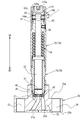
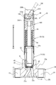
- FIG. 2 is a cross-sectional view of a manual valve device according to an embodiment of the present invention, showing a valve closed state.
- FIG. 1B is a top view of the manual valve device of FIG. 1A.
- FIG. 1B is a cross-sectional view of the manual valve device of FIG. 1A showing the valve open.
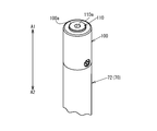
- It is a principal part external appearance perspective view of the manual valve apparatus of FIG. 1A, and a figure which shows a valve closed state.
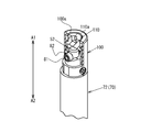
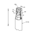
- It is a principal part external appearance perspective view of the manual valve apparatus of FIG. 2 Comprising: The figure which shows a valve open state.
- FIG. 9B is a top view of the manual valve device of FIG. 9A. It is sectional drawing of the manual valve apparatus of FIG. 9A, Comprising: The figure which shows valve open state.
- FIG. 10B is a top view of the manual valve device of FIG. 10A. It is a principal part external appearance perspective view of the manual valve apparatus of FIG. 9A, and a figure which shows a valve closed state.
- FIG. 10A It is a principal part external appearance perspective view of the manual valve apparatus of FIG. 10A, Comprising: The figure which shows a valve open state.
- the perspective view which shows the internal structure of the manual valve apparatus of FIG. 12A, partially including a cross section.
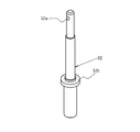
- External perspective view of movable rod The external appearance perspective view of a casing member.
- the external appearance perspective view of a receiving member The external appearance perspective view of an operation member.
- FIG. BRIEF DESCRIPTION OF THE DRAWINGS The perspective view which shows an example of the fluid control apparatus with which the manual valve of this invention is applied.
- FIG. 17 An example of a fluid control device to which the present invention is applied will be described with reference to FIG.
- five rail members 500 arranged along the width directions W1 and W2 and extending in the longitudinal directions G1 and G2 are provided on a metal base plate BS.
- W1 indicates the front side
- W2 indicates the back side
- G1 indicates the upstream side
- G2 indicates the downstream side.
- various fluid devices 210A to 210E are installed via a plurality of flow path blocks 200, and a plurality of flow path blocks 200 allow the flow of fluid from the upstream side to the downstream side. Are formed respectively.
- the "fluid device” is a device used in a fluid control device that controls the flow of fluid, and includes a body that defines a fluid flow passage, and at least two flow passage ports that open at the surface of the body
- the introduction pipe 310 is connected to a flow path port on the upstream side of the flow path (not shown) described above.
- fluid devices are miniaturized and integrated, as can be seen from FIG. 17, they are generally elongated, and it can be seen that almost no gap exists between adjacent fluid devices in the width direction W1 and W2.
- the manual valve device of the present invention can be applied, for example, to the position of the on-off valve 210A.
- FIG. 1 In the drawing, arrows A1 and A2 indicate the vertical direction, A1 indicates the upward direction, and A2 indicates the downward direction.
- the manual valve device 1 has a valve body 20, a diaphragm 40 as a valve body, a drive mechanism 50, a casing 70 incorporating the drive mechanism 50, a protective cover 100, and an operation member 110.
- the valve body 20 defines opposite top and bottom surfaces 20a and 20b, and the bottom surface 20b.
- the flow paths 21 and 22 of gas etc. which have the opening parts 21a and 22a are demarcated.
- the flow paths 21 and 22 are connected to other flow path members via seal members (not shown).
- the valve body 20 is formed with through holes 23 and 24 penetrating the top surface 20 a and the bottom surface 20 b.
- the through holes 23 and 24 are holes for fastening bolts for fixing the valve body 20 to the flow path block 200 described above.
- the valve seat 30 is provided around the flow passage 21 of the valve body 20.
- the valve seat 30 is made of a resin such as PFA or PTFE so as to be elastically deformable.
- the diaphragm 40 functions as a valve body, has a diameter larger than that of the valve seat 30, and is formed so as to be elastically deformable in a spherical shell shape from a metal such as stainless steel or NiCo alloy or a fluorine resin.
- the diaphragm 40 is supported by the valve body 20 so as to be able to abut and be separated from the valve seat 30 by being pressed toward the valve body 20 by the lower end surface of the casing member 71 via the pressing adapter 42.
- the diaphragm 40 is pressed by the diaphragm presser 51 to be elastically deformed and pressed against the valve seat 30.
- the pressure by the diaphragm presser 51 is released, it is restored to a spherical shape.
- the flow passage 21 is closed.
- the flow passage 21 is opened and communicated with the flow passage 22.
- the casing 70 comprises cylindrically formed casing members 71 and 72 connected to each other, and is fixed to the valve body 20 by screwing the lower end portion of the casing member 71 to the upper side of the valve body 20.
- the drive mechanism 50 has a diaphragm presser 51, a movable rod 52 and a coil spring 54.
- the diaphragm presser 51 and the movable rod 52 are held movably in the vertical direction A1 and A2 in the casing 70, and the movable rod 52 is configured such that a flange 52b formed halfway is in contact with the upper end surface of the casing member 71. Thus, the movement in the downward direction A2 is restricted.
- the coil spring 54 is interposed between the collar 52 b of the movable rod 52 and the casing member 72, and always biases the movable rod 52 in the downward direction A 2 by a restoring force.
- the manual valve device 1 is a normally closed valve whose flow passage 21 is normally closed by a diaphragm 40. As shown in FIGS. 1A and 2, a pin hole 52a penetrating in a direction perpendicular to the central axis of the movable rod 52 is formed at the upper end portion of the movable rod 52, and the pin 81 is inserted into the pin hole 52a.
- the roller members 82 are fitted at both ends of the pin 81.
- a cam surface 80 is formed at the upper end of the casing member 72, and the force of the cam surface 80 and the roller member 82 described above acting on the operation member 110 is used as the driving force of the drive mechanism 50.
- the cam part to convert is comprised (refer FIG. 4B).
- the cam surface 80 has a first locking portion 80a to which the roller member 82 can be locked and a second locking portion 80b formed at a position lower than the first locking portion 80a in the vertical directions A1 and A2.
- the first locking portion 80a and the second locking portion 80b are respectively formed at two symmetrical positions, and the first locking portion 80a and the second locking portion 80b are mutually 90 degrees with respect to the central axis of the casing member 72. It is formed at a distant position. That is, the manual valve device 1 is configured to open and close the flow path 21 by rotating the operation member 110 in the forward and reverse directions by 90 degrees.
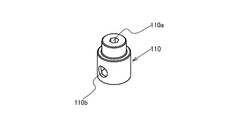
- the operation member 110 is a cylindrical member whose upper end is closed, and an insertion hole 110b into which a part of the above-mentioned roller member 82 is inserted is formed at a symmetrical position of the cylindrical portion. It is done.
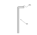
- a mounting recess 110a is formed in which a tip end portion 600a of a torque wrench 600 as an auxiliary tool as shown in FIG. 8 is detachably fitted.
- the protective cover 100 is a cylindrical member, connected to the upper end of the casing member 72 and fixed by a screw member.
- the opening 100 a on the upper end side of the protective cover 100 is formed in a diameter such that the cylindrical portion on the upper end side of the operation member 110 can be inserted.
- FIG. 1B is a top view of the manual valve device 1, in which B1 and B2 indicate the longitudinal direction (flow direction of fluid) of the valve body 20, and C1 and C2 indicate the width direction.
- the protective cover 100 and the operation member 110 are contained in the outer shape of the casing 70 and in the outer shape of the upper surface 20 a of the valve body 20. Therefore, the manual valve device 1 can be applied to a fluid control device in which fluid devices are miniaturized and integrated as shown in FIG.
- the roller member 82 held at both ends of the pin 81 is partially inserted into the insertion hole 110 b of the operation member 110 as shown in FIG. 2, so that the force between the operation member 110 and the movable rod 52 is obtained. Transmission is possible. Further, a protective cover 100 is provided on the outer periphery of the operation member 110, and the inner peripheral surface of the protective cover 100 restricts the axial movement of the roller member 82 with respect to the pin 81 so that the roller member 82 does not fall off the pin 81 It is supposed to be.
- the roller member 82 In the closed state as shown in FIG. 1A, the roller member 82 is positioned at the second locking portion 80 b located on the lower side of the cam surface 80. Further, as shown in FIGS. 3A and 3B, the entire operation member 110 is housed in the protective cover 100. From this state, in order to bring it into the open state shown in FIG. 2, the torque wrench 600 is attached to the mounting recess 110 a of the operation member 110, and the operation member 110 is rotated about the central axis of the casing 70. The roller member 82 receives a cam action of moving from the cam surface 80 in the upward direction A1 side, and the movable rod 52 moves in the upward direction A1 against the biasing force of the coil spring 54. As shown in FIGS.
- a pin hole 52 a penetrating in a direction orthogonal to the central axis of the movable rod 52 is formed at the upper end portion of the movable rod 52.
- the pin 90 shown in FIGS. 9A and 10A is inserted into the pin hole 52a.
- the operation member 210 is provided with a mounting recess 210a to which the tip of the round bar-like auxiliary lever 700 shown by dotted lines in FIGS. 9A and 10A is removably mounted. And the opposite wall portion 210b extending in parallel downward.
- each of the opposing wall portions 210b is a cam surface 210f that slopes and curves, and a pin hole 210h is formed in the opposing wall portion 210b perpendicularly to the wall surface.
- the above-described pin 90 is inserted into the two pin holes 210h.
- the movement of the pin 90 is restricted by the inner peripheral surface of the protective cover 400 by inserting and fixing the cylindrically formed protective cover 400 to the upper end portion of the casing member 73 shown in FIG. And the pin holes 210h.
- a locking convex portion 210g curved in a convex shape is formed on one end side of the cam surface 210f of the operation member 210, and the locking convex portion 210g is a member of the receiving member 180 described later.
- the movement of the operation member 210 can be locked by fitting into the locking recess 180t.
- the receiving member 180 includes a through hole 180h into which the upper end portion of the movable rod 52 is inserted, two projecting portions 180a formed to sandwich the movable rod 52, and two projecting portions 180a. And a receiving surface 180 f formed on both sides and engaged with the cam surface 210 f of the operating member 210. In the receiving surface 180f, a locking recess 180t is formed where a part of the operation member 210 is locked.
- the opposing surfaces of the two protrusions 180a are curved surfaces 180b that are curved so that the movable rod 52 can pass through.
- the protective cover 400 is a cylindrical member as described above, and is provided with the protective wall portions 200 b facing each other at the upper end portion.
- the operation member 210 is disposed so that the majority thereof is sandwiched between the protective wall portions 200 b, and the protective wall portion 200 b prevents an object or the like from unintentionally colliding with the operation member 210.
- FIGS. 9B and 10B are top views of the manual valve device 1B, in which B1 and B2 are the longitudinal direction (flow direction of fluid) of the valve body 20, and C1 and C2 are the width direction.
- the protective cover 400 and the operating member 210 fit within the outline of the top surface 20a of the valve body 20. Therefore, the manual valve device 1B can be applied to a fluid control device in which the fluid device is miniaturized and integrated as shown in FIGS. 9A and 9B.
- the cam surface 210f of the operation member 210 is in a state of being separated from the receiving surface 180f of the receiving member 180. From this state, as shown in FIGS. 10A and 12B using the auxiliary lever 700, when the operating member 210 is tilted against the biasing force of the coil spring 54, the operating member 210 is moved by the cam action of the cam surface 210f. The movable rod 52 coupled thereto moves in the upward direction A1 to open the valve. At this time, as shown in FIGS. 10A and 12B, the engagement convex portion 210g of the operation member 210 is fitted into the engagement concave portion 180t formed in the receiving member 180, whereby the posture of the operation member 210 is maintained and the valve The open state is maintained.
- the open / close state of the valve can be determined by the attitude of the operation member 210.
- the open / close indicator on the surface of the projecting portion 180a of the receiving member 180, the visibility of the open / close state of the valve is improved.
- cam surface of the cam portion is formed on the operating member and the receiving surface is formed on the receiving member in the above embodiment, the cam surface is formed on the receiving member side and the receiving surface is formed on the operating member side It is also possible.
- Embodiments 1 and 2 of the present invention illustrate a normally closed manual valve device
- the present invention is not limited to this, and is applicable to a normally open manual valve device. .
- valve body 20a upper surface 20b: bottom surface 21: flow path 21a: opening 22: flow path 22a: opening 23, 24: through hole 30: valve seat 40: diaphragm 42: presser adapter 50: Drive mechanism 51: Diaphragm presser 52: Movable rod 52a: Pin hole 52b: Flange 54: Coil spring 70: Casing 71, 72, 73: Casing member 80: Cam surface 80a: First locking portion 80b: Second Locking portion 81: Pin 82: Roller member 90: Pin 100: Protective cover 100a: Opening 110: Operating member 110a: Mounting recess 110b: Insertion hole 180: Receiving member 180a: Projection 180b: Curved surface 180f: Receiving surface 180h: Through hole 180t: Locking recess 200: Channel block 2 0b: Protective wall portion 210: Operating member 210A: On-off valve 210B: Regulator 210C: Pressure gauge 210D: Fluid device 210E: Mass flow controller
Landscapes
- Engineering & Computer Science (AREA)
- General Engineering & Computer Science (AREA)
- Mechanical Engineering (AREA)
- Mechanically-Actuated Valves (AREA)
Abstract
小型化、集積化された流体制御装置に適した手動バルブ装置を提供する。駆動機構(50)を内蔵する筒状のケーシング(70)と、駆動機構(50)を作動させるための操作部材(110)と、当該操作部材(110)に作用する力を当該駆動機構の駆動力に変換するカム部(80)とを有する手動バルブ装置であって、ケーシング(70)の上端側に設けられ、操作部材(110)の少なくとも一部を覆う保護カバー(100)を有し、操作部材(110)は、駆動機構(50)の作動に必要な力を操作部材(110)に作用させるための補助工具(600)を取り外し可能に装着させる装着部(110a)を有し、保護カバー(100)は、操作部材(110)の装着部(110a)への補助工具(600)のアクセスを可能に形成されている。
Description
本発明は、手動バルブ装置およびこのバルブ装置を含む流体機器が集積化された流体制御装置に関する。
例えば、半導体製造装置等のチャンバへ各種のプロセスガスを供給するために使用される流体制御装置としては、下記の引用文献1等に開示されたものが知られている。
上記のような流体制御装置の分野においては、プロセスガスの供給制御により高い応答性が求められており、このためには流体制御装置をできるだけ小型化、集積化することが進められている。
上記のような流体制御装置の分野においては、プロセスガスの供給制御により高い応答性が求められており、このためには流体制御装置をできるだけ小型化、集積化することが進められている。
ところで、上記のような流体制御装置では、通常は使用されないが、緊急時や装置の全停止を実施する際に使用される手動バルブを含む。このような手動バルブは、手動操作用のハンドルやレバーを備えているため、これらの部品は、他の自動バルブ装置等の流体機器の小型化に合わせて、小型化すると手動操作が困難になるため、小型化が難しいという問題があった。
また、手動バルブが意図せず操作されるのを防ぐためには、手動操作用のハンドルやレバーに保護枠、キャップ、カバー等を設け、開閉状態を示すインジケータも設ける必要があり、さらに小型化が困難となる。
また、手動バルブが意図せず操作されるのを防ぐためには、手動操作用のハンドルやレバーに保護枠、キャップ、カバー等を設け、開閉状態を示すインジケータも設ける必要があり、さらに小型化が困難となる。
本発明の一の目的は、小型化、集積化された流体制御装置に適した手動バルブ装置を提供することにある。
本発明の他の目的は、上記の手動バルブ装置を含む小型化、集積化された流体制御装置を提供することにある。
本発明の他の目的は、上記の手動バルブ装置を含む小型化、集積化された流体制御装置を提供することにある。
上記目的を達成するための本第1発明の手動バルブ装置は、対向する底面及び上面を画定するとともに流体流路を画定するブロック状のバルブボディと、前記バルブボディの流路を開閉可能に設けられた弁体と、前記弁体を開閉方向に駆動する駆動機構と、前記バルブボディに接続されて当該バルブボディの上面から上方に向けて延在し前記駆動機構を内蔵する筒状のケーシングと、前記駆動機構を作動させるための操作部材と、当該操作部材に作用する力を当該駆動機構の駆動力に変換するカム部とを有する手動バルブ装置であって、
前記ケーシングの上端側に設けられ、前記操作部材の少なくとも一部を覆う保護カバーを有し、
前記操作部材は、前記駆動機構の作動に必要な力を当該操作部材に作用させるための補助工具を取り外し可能に装着させる装着部を有し、
前記保護カバーは、前記操作部材の装着部への前記工具のアクセスおよび操作を可能にするように形成されている、ことを特徴とする。
前記ケーシングの上端側に設けられ、前記操作部材の少なくとも一部を覆う保護カバーを有し、
前記操作部材は、前記駆動機構の作動に必要な力を当該操作部材に作用させるための補助工具を取り外し可能に装着させる装着部を有し、
前記保護カバーは、前記操作部材の装着部への前記工具のアクセスおよび操作を可能にするように形成されている、ことを特徴とする。
好適には、前記操作部材および保護カバーは、上面視において、前記ケーシングの外形内に収まるように形成されている、構成を採用できる。さらに好適には、前記装着部は、凹状に形成されている、構成を採用できる。
好適には、前記操作部材は、前記ケーシングの中心軸線を中心に回転可能に保持され、
前記保護カバーは、前記操作部材の外周を覆い、
前記装着部は、前記操作部材の上端面に形成されている、構成を採用できる。
前記保護カバーは、前記操作部材の外周を覆い、
前記装着部は、前記操作部材の上端面に形成されている、構成を採用できる。
さらに好適には、前記駆動機構は、前記弁体を開閉する方向に移動可能に保持された可動ロッドと、
前記カム部に形成されたカム面上を移動可能で、かつ、前記可動ロッドに回転可能に保持されたローラ部材と、を有し、
前記カム面は、前記ローラ部材が係止して前記操作部材を開放位置と閉鎖位置とに保持する係止部を有する、構成を採用できる。
前記カム部に形成されたカム面上を移動可能で、かつ、前記可動ロッドに回転可能に保持されたローラ部材と、を有し、
前記カム面は、前記ローラ部材が係止して前記操作部材を開放位置と閉鎖位置とに保持する係止部を有する、構成を採用できる。
好適には、前記操作部材は、前記流路が開放又は閉鎖されると前記操作部材の上端部の一部が前記保護部材から突出した状態に維持され、前記流路が開放又は閉鎖状態から閉鎖又は開放されると、当該操作部材の全体が前記保護部材の内部に収容された状態に維持される、構成を採用できる。
また、上記目的を達成するための本第2発明の手動バルブ装置は、対向する底面及び上面を画定するとともに流体流路を画定するブロック状のバルブボディと、前記バルブボディの流路を開閉可能に設けられた弁体と、前記弁体を開閉方向に駆動する駆動機構と、前記バルブボディに接続されて当該バルブボディの上面から上方に向けて延在する筒状のケーシングと、前記駆動機構を作動させるための操作部材と、当該操作部材に作用する傾動力を当該駆動機構の駆動力に変換するカム部とを有する手動バルブ装置であって、
前記ケーシングの上端側に設けられ、前記操作部材の少なくとも一部を覆う保護カバーを有し、
前記操作部材は、前記駆動機構の作動に必要な傾動力を当該操作部材に作用させるための補助レバーを取り外し可能に装着させる装着部を有し、
前記保護カバーは、前記操作部材の装着部への前記補助レバーのアクセスを可能にするように形成されている、ことを特徴とする。
前記ケーシングの上端側に設けられ、前記操作部材の少なくとも一部を覆う保護カバーを有し、
前記操作部材は、前記駆動機構の作動に必要な傾動力を当該操作部材に作用させるための補助レバーを取り外し可能に装着させる装着部を有し、
前記保護カバーは、前記操作部材の装着部への前記補助レバーのアクセスを可能にするように形成されている、ことを特徴とする。
好適には、前記装着部は、凹状に形成されている、構成を採用できる。
好適には、前記駆動機構は、前記弁体を開閉する方向に移動可能に保持された可動ロッドを有し、
前記操作部材は、所定軸線を中心に傾動可能に前記可動ロッドに連結され、
前記カム部は、前記操作部材に形成されたカム面と、当該カム面と係合し前記操作部材に作用する傾動力を受ける受け面とを有する、構成を採用できる。
前記操作部材は、所定軸線を中心に傾動可能に前記可動ロッドに連結され、
前記カム部は、前記操作部材に形成されたカム面と、当該カム面と係合し前記操作部材に作用する傾動力を受ける受け面とを有する、構成を採用できる。
さらに好適には、前記受け面を有する受け部材は、前記可動ロッドが貫通する貫通孔を有し、前記保護カバー内で前記ケーシングに保持されている、構成を採用できる。また、
前記受け面を有する受け部材は、前記可動ロッドが貫通する貫通孔を有し、前記保護カバー内で前記ケーシングに保持されている、構成を採用できる。
前記受け面を有する受け部材は、前記可動ロッドが貫通する貫通孔を有し、前記保護カバー内で前記ケーシングに保持されている、構成を採用できる。
本発明の流体制御装置は、複数の流体機器を有する流体制御装置であって、
前記流体機器に上記構成の手動バルブ装置が含まれる、ことを特徴とする。
前記流体機器に上記構成の手動バルブ装置が含まれる、ことを特徴とする。
本発明によれば、小型化、集積化された流体制御装置に適した手動バルブ装置を得られるとともに、手動バルブ装置が意図せず操作されるのを確実に防ぐことができる。
以下、本第1発明及び第2発明の実施形態について図面を参照して説明する。
先ず、図17を参照して、本発明が適用される流体制御装置の一例を説明する。
図17に示す流体制御装置は、金属製のベースプレートBS上には、幅方向W1,W2に沿って配列され長手方向G1,G2に延びる5本のレール部材500が設けられている。なお、W1は正面側、W2は背面側,G1は上流側、G2は下流側の方向を示している。各レール部材500には、複数の流路ブロック200を介して各種流体機器210A~210Eが設置され、複数の流路ブロック200によって、上流側から下流側に向かって流体が流通する図示しない流路がそれぞれ形成されている。
ここで、「流体機器」とは、流体の流れを制御する流体制御装置に使用される機器であって、流体流路を画定するボディを備え、このボディの表面で開口する少なくとも2つの流路口を有する機器である。具体的には、開閉弁(2方弁)210A、レギュレータ210B、プレッシャーゲージ210C、開閉弁(3方弁)210D、マスフローコントローラ210E等が含まれるが、これらに限定されるわけではない。なお、導入管310は、上記した図示しない流路の上流側の流路口に接続されている。
流体機器を小型化、集積化していくと、図17から分かるように、全体的に細長く形成され、幅方向W1,W2の隣り合う流体機器間にはほとんど隙間が存在しないのがわかる。
本発明の手動バルブ装置は、例えば、開閉弁210Aの位置に適用されうる。
先ず、図17を参照して、本発明が適用される流体制御装置の一例を説明する。
図17に示す流体制御装置は、金属製のベースプレートBS上には、幅方向W1,W2に沿って配列され長手方向G1,G2に延びる5本のレール部材500が設けられている。なお、W1は正面側、W2は背面側,G1は上流側、G2は下流側の方向を示している。各レール部材500には、複数の流路ブロック200を介して各種流体機器210A~210Eが設置され、複数の流路ブロック200によって、上流側から下流側に向かって流体が流通する図示しない流路がそれぞれ形成されている。
ここで、「流体機器」とは、流体の流れを制御する流体制御装置に使用される機器であって、流体流路を画定するボディを備え、このボディの表面で開口する少なくとも2つの流路口を有する機器である。具体的には、開閉弁(2方弁)210A、レギュレータ210B、プレッシャーゲージ210C、開閉弁(3方弁)210D、マスフローコントローラ210E等が含まれるが、これらに限定されるわけではない。なお、導入管310は、上記した図示しない流路の上流側の流路口に接続されている。
流体機器を小型化、集積化していくと、図17から分かるように、全体的に細長く形成され、幅方向W1,W2の隣り合う流体機器間にはほとんど隙間が存在しないのがわかる。
本発明の手動バルブ装置は、例えば、開閉弁210Aの位置に適用されうる。
<実施形態1>
次に、図1A~図7を参照して、本第1発明の一実施形態に係る手動バルブ装置について説明する。なお、図中において、矢印A1,A2は上下方向を示しており、A1が上方向、A2が下方向を示している。
手動バルブ装置1は、バルブボディ20と、弁体としてのダイヤフラム40と、駆動機構50と、駆動機構50を内蔵するケーシング70と、保護カバー100と、操作部材110とを有する。
次に、図1A~図7を参照して、本第1発明の一実施形態に係る手動バルブ装置について説明する。なお、図中において、矢印A1,A2は上下方向を示しており、A1が上方向、A2が下方向を示している。
手動バルブ装置1は、バルブボディ20と、弁体としてのダイヤフラム40と、駆動機構50と、駆動機構50を内蔵するケーシング70と、保護カバー100と、操作部材110とを有する。
バルブボディ20は、対向する上面20a及び底面20bを画定しており、底面20b
に開口部21a,22aを有するガス等の流路21,22を画定している。流路21,22は他の流路部材と図示しないシール部材を介して接続される。バルブボディ20には、上面20aと底面20bとを貫通する貫通孔23,24が形成されている。これらの貫通孔23,24は、上記した流路ブロック200にバルブボディ20を固定するための締結ボルト用の孔である。
に開口部21a,22aを有するガス等の流路21,22を画定している。流路21,22は他の流路部材と図示しないシール部材を介して接続される。バルブボディ20には、上面20aと底面20bとを貫通する貫通孔23,24が形成されている。これらの貫通孔23,24は、上記した流路ブロック200にバルブボディ20を固定するための締結ボルト用の孔である。
バルブシート30は、バルブボディ20の流路21の周囲に設けられている。バルブシート30は、PFA、PTFE等の樹脂で弾性変形可能に形成されている。
ダイヤフラム40は、弁体として機能し、バルブシート30よりも大きな直径を有し、ステンレス、NiCo系合金などの金属やフッ素系樹脂で球殻状に弾性変形可能に形成されている。ダイヤフラム40は、押えアダプタ42を介してケーシング部材71の下端面によりバルブボディ20に向けて押し付けられることによりバルブシート30に対して当接離隔可能にバルブボディ20に支持されている。図1Aにおいて、ダイヤフラム40はダイヤフラム押え51により押圧されて弾性変形し、バルブシート30に押し付けられている状態にある。ダイヤフラム押え51による押圧を開放すると、球殻状に復元する。ダイヤフラム40がバルブシート30に押し付けられている状態では、流路21が閉鎖されている。図2に示すように、ダイヤフラム40がバルブシート30から離れると、流路21は開放され、流路22と連通する。
ダイヤフラム40は、弁体として機能し、バルブシート30よりも大きな直径を有し、ステンレス、NiCo系合金などの金属やフッ素系樹脂で球殻状に弾性変形可能に形成されている。ダイヤフラム40は、押えアダプタ42を介してケーシング部材71の下端面によりバルブボディ20に向けて押し付けられることによりバルブシート30に対して当接離隔可能にバルブボディ20に支持されている。図1Aにおいて、ダイヤフラム40はダイヤフラム押え51により押圧されて弾性変形し、バルブシート30に押し付けられている状態にある。ダイヤフラム押え51による押圧を開放すると、球殻状に復元する。ダイヤフラム40がバルブシート30に押し付けられている状態では、流路21が閉鎖されている。図2に示すように、ダイヤフラム40がバルブシート30から離れると、流路21は開放され、流路22と連通する。
ケーシング70は、円筒状に形成され互いに接続されたケーシング部材71,72からなり、ケーシング部材71の下端部がバルブボディ20の上側に螺合することにより、バルブボディ20に固定されている。
駆動機構50は、ダイヤフラム押え51、可動ロッド52およびコイルばね54を有する。ダイヤフラム押え51および可動ロッド52はケーシング70内を上下方向A1,A2に移動可能に保持されており、可動ロッド52は、中途に形成された鍔部52bがケーシング部材71の上端面に当接することにより、下方向A2への移動が規制される。
コイルばね54は、可動ロッド52の鍔部52bとケーシング部材72との間に介在し、復元力により、可動ロッド52を下方向A2へ向けて常時付勢している。手動バルブ装置1は、通常は流路21がダイヤフラム40により閉鎖されたノーマリクローズのバルブである。
図1Aおよび図2に示すように、可動ロッド52の上端部には、可動ロッド52の中心軸線に対して直交する向きに貫通するピン孔52aが形成され、このピン孔52aにピン81が挿入され、ピン81の両端部にローラ部材82が嵌め込まれている。
駆動機構50は、ダイヤフラム押え51、可動ロッド52およびコイルばね54を有する。ダイヤフラム押え51および可動ロッド52はケーシング70内を上下方向A1,A2に移動可能に保持されており、可動ロッド52は、中途に形成された鍔部52bがケーシング部材71の上端面に当接することにより、下方向A2への移動が規制される。
コイルばね54は、可動ロッド52の鍔部52bとケーシング部材72との間に介在し、復元力により、可動ロッド52を下方向A2へ向けて常時付勢している。手動バルブ装置1は、通常は流路21がダイヤフラム40により閉鎖されたノーマリクローズのバルブである。
図1Aおよび図2に示すように、可動ロッド52の上端部には、可動ロッド52の中心軸線に対して直交する向きに貫通するピン孔52aが形成され、このピン孔52aにピン81が挿入され、ピン81の両端部にローラ部材82が嵌め込まれている。
図5に示すように、ケーシング部材72の上端には、カム面80が形成されており、このカム面80と上記したローラ部材82が操作部材110に作用する力を駆動機構50の駆動力に変換するカム部を構成する(図4B参照)。カム面80には、ローラ部材82が係止可能な第1係止部80aと、上下方向A1,A2において第1係止部80aよりも低い位置に形成された第2係止部80bとを有する。第1係止部80aおよび第2係止部80bは、それぞれ対称な2カ所に形成され、第1係止部80aと第2係止部80bとは、ケーシング部材72の中心軸線に関して互いに90度離れた位置に形成されている。すなわち、手動バルブ装置1は、操作部材110を正逆方向に90度回転させることで、流路21を開閉するようになっている。
図6Aおよび図6Bに示すように、操作部材110は、上端部が閉塞した円筒状部材であり、円筒部分の対称な位置に上記したローラ部材82の一部が挿入される挿入孔110bが形成されている。上端側の中心部には、図8に示すような補助工具としてのトルクレンチ600の先端部600aが着脱自在に嵌る装着凹部110aが形成されている。
保護カバー100は、図7に示すように、円筒状部材であり、ケーシング部材72の上端部に接続されねじ部材で固定されている。保護カバー100の上端側の開口100aは、操作部材110の上端側の円柱部分が挿入可能な直径に形成されている。
保護カバー100は、図7に示すように、円筒状部材であり、ケーシング部材72の上端部に接続されねじ部材で固定されている。保護カバー100の上端側の開口100aは、操作部材110の上端側の円柱部分が挿入可能な直径に形成されている。
ここで、図1Bは手動バルブ装置1の上面視であり、図中B1,B2はバルブボディ20の長手方向(流体の流通方向)であり、C1,C2が幅方向である。図1Bからわかるように、保護カバー100および操作部材110は、ケーシング70の外形内に収まっており、かつ、バルブボディ20の上面20aの外形内に収まっている。このため、図17に示したような、流体機器が小型化、集積化された流体制御装置に手動バルブ装置1を適用可能となる。
ピン81の両端部に保持されたローラ部材82は、図2に示すように、一部が操作部材110の挿入孔110bに挿入されることにより、操作部材110と可動ロッド52との間の力の伝達が可能になる。また、操作部材110の外周には、保護カバー100が設けられ、この保護カバー100の内周面によりローラ部材82のピン81に対する軸線方向の移動を規制し、ローラ部材82がピン81から脱落しないようになっている。
図1Aに示すような閉鎖状態では、ローラ部材82は、カム面80の低位側に位置する第2係止部80bに位置付けられている。また、図3Aおよび図3Bに示すように、操作部材110の全体は、保護カバー100内に収容された状態にある。
この状態から、図2に示す開放状態にするには、トルクレンチ600を操作部材110の装着凹部110aに装着し、操作部材110をケーシング70の中心軸線を中心に回転させる。ローラ部材82はカム面80から上方向A1側に移動するカム作用を受け、可動ロッド52がコイルばね54の付勢力に抗して上方向A1に移動する。図4Aおよび図4Bに示すように、操作部材110を90度回転させたところで、ローラ部材82は、高位側に位置する第1係止部80aに位置付けられて係止する。ローラ部材82の動きに伴って、操作部材110は、図4Aおよび図4Bに示すように、上方向A1に移動し、上端部の一部が保護カバー100の上端面から突出した状態となる。
このように、操作部材110の保護カバー100に対する位置から、手動バルブ装置1の開閉状態を判別できる。
この状態から、図2に示す開放状態にするには、トルクレンチ600を操作部材110の装着凹部110aに装着し、操作部材110をケーシング70の中心軸線を中心に回転させる。ローラ部材82はカム面80から上方向A1側に移動するカム作用を受け、可動ロッド52がコイルばね54の付勢力に抗して上方向A1に移動する。図4Aおよび図4Bに示すように、操作部材110を90度回転させたところで、ローラ部材82は、高位側に位置する第1係止部80aに位置付けられて係止する。ローラ部材82の動きに伴って、操作部材110は、図4Aおよび図4Bに示すように、上方向A1に移動し、上端部の一部が保護カバー100の上端面から突出した状態となる。
このように、操作部材110の保護カバー100に対する位置から、手動バルブ装置1の開閉状態を判別できる。
<実施形態2>
次に、図9A~図16Bを参照して、本第2発明の一実施形態(実施形態2)に係る手動バルブ装置について説明する。なお、実施形態1の手動バルブと同様の構造については説明を省略する。
次に、図9A~図16Bを参照して、本第2発明の一実施形態(実施形態2)に係る手動バルブ装置について説明する。なお、実施形態1の手動バルブと同様の構造については説明を省略する。
実施形態2に係る手動バルブは、図13に示すように、可動ロッド52の上端部には、可動ロッド52の中心軸線に対して直交する向きに貫通するピン孔52aが形成されており、このピン孔52aには、図9Aおよび図10Aに示したピン90が挿入される。
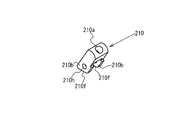
また、図16Aおよび図16Bに示すように、操作部材210は、図9A、10Aに点線で示した丸棒状の補助レバー700の先端が取り外し可能に装着される装着凹部210aが形成され、上端側から下方に向けて平行に延びる対向壁部210bを有する。対向壁部210bのそれぞれの下端面側は傾斜および湾曲するカム面210fとなっており、また、対向壁部210bには壁面に垂直にピン孔210hが形成されている。2つのピン孔210hには上記したピン90が挿入される。
操作部材210の2つの対向壁部210bの間に可動ロッド52の上端部が挿入され、ピン孔52aおよびピン孔210hにピン90が挿入されると、操作部材210はピン90を中心に可動ロッド52に対して傾動自在に保持される。なお、ピン90は、円筒状に形成された保護カバー400を、図14に示すケーシング部材73の上端部に挿入固定することで、保護カバー400の内周面により移動が規制され、ピン孔52aおよびピン孔210hから脱落しないようになっている。
また、図16Bに示すように、操作部材210のカム面210fの一端側には凸状に湾曲する係止凸部210gが形成されており、この係止凸部210gが後述する受け部材180の係止凹部180tに嵌ることにより、操作部材210の動きをロックできるようになっている。
また、図16Aおよび図16Bに示すように、操作部材210は、図9A、10Aに点線で示した丸棒状の補助レバー700の先端が取り外し可能に装着される装着凹部210aが形成され、上端側から下方に向けて平行に延びる対向壁部210bを有する。対向壁部210bのそれぞれの下端面側は傾斜および湾曲するカム面210fとなっており、また、対向壁部210bには壁面に垂直にピン孔210hが形成されている。2つのピン孔210hには上記したピン90が挿入される。
操作部材210の2つの対向壁部210bの間に可動ロッド52の上端部が挿入され、ピン孔52aおよびピン孔210hにピン90が挿入されると、操作部材210はピン90を中心に可動ロッド52に対して傾動自在に保持される。なお、ピン90は、円筒状に形成された保護カバー400を、図14に示すケーシング部材73の上端部に挿入固定することで、保護カバー400の内周面により移動が規制され、ピン孔52aおよびピン孔210hから脱落しないようになっている。
また、図16Bに示すように、操作部材210のカム面210fの一端側には凸状に湾曲する係止凸部210gが形成されており、この係止凸部210gが後述する受け部材180の係止凹部180tに嵌ることにより、操作部材210の動きをロックできるようになっている。
受け部材180は、図15に示すように、可動ロッド52の上端部が挿入される貫通孔180hと、可動ロッド52を挟むように形成された2つの突出部180aと、2つの突出部180aの両側に形成され操作部材210のカム面210fが係合する受け面180fとを有する。受け面180fには、操作部材210の一部が係止する係止凹部180tが形成されている。2つの突出部180aの対向面は、可動ロッド52が通過できるように湾曲する湾曲面180bとなっている。
保護カバー400は、上記したように円筒状の部材であり、上端部に互いに対向する保護壁部200bを備える。操作部材210は、その大部分は保護壁部200bの間に挟まれるように配置されるようになっており、保護壁部200bは、操作部材210に不意に物体等が衝突するのを防いでいる。
ここで、図9Bおよび図10Bは、手動バルブ装置1Bの上面視であり、図中B1,B2はバルブボディ20の長手方向(流体の流通方向)であり、C1,C2が幅方向である。図9Bおよび図10Bからわかるように、保護カバー400および操作部材210は、バルブボディ20の上面20aの外形内に収まっている。このため、図9A、図9Bに示したような、流体機器が小型化、集積化された流体制御装置に手動バルブ装置1Bを適用可能となる。
ここで、図9Bおよび図10Bは、手動バルブ装置1Bの上面視であり、図中B1,B2はバルブボディ20の長手方向(流体の流通方向)であり、C1,C2が幅方向である。図9Bおよび図10Bからわかるように、保護カバー400および操作部材210は、バルブボディ20の上面20aの外形内に収まっている。このため、図9A、図9Bに示したような、流体機器が小型化、集積化された流体制御装置に手動バルブ装置1Bを適用可能となる。
図9Aおよび図11Bに示すような閉鎖状態では、操作部材210のカム面210fは受け部材180の受け面180fから離隔した状態にある。この状態から、補助レバー700を用いて、図10Aおよび図12Bに示すように、操作部材210をコイルばね54の付勢力に抗して傾動させると、カム面210fのカム作用により、操作部材210に連結された可動ロッド52が上方向A1に移動し、バルブが開放された状態となる。このとき、図10Aおよび図12Bに示すように、操作部材210の係止凸部210gが受け部材180に形成された係止凹部180tに嵌ることで、操作部材210の姿勢が保持され、バルブが開放された状態が維持される。
本実施形態では、操作部材210の姿勢によってバルブの開閉状態を判別できるが、受け部材180の突出部180aの表面に開閉を示すインジケータを記すことにより、バルブの開閉状態の視認性が向上する。
上記実施形態では、カム部のカム面を操作部材に形成し、受け面を受け部材に形成した場合を例示したが、カム面を受け部材側に形成し、受け面を操作部材側に形成することも可能である。
以上のように、本発明によれば、流体機器が小型化、集積化された流体制御装置に適用するのに好ましい手動バルブ装置が得られる。
上記本発明の実施形態1~2では、ノーマリークローズタイプの手動バルブ装置を例示したが、本発明はこれに限定されるわけではなく、ノーマリーオープンタイプの手動バルブ装置にも適用可能である。
1,1B :手動バルブ装置
20 :バルブボディ
20a :上面
20b :底面
21 :流路
21a :開口部
22 :流路
22a :開口部
23,24:貫通孔
30 :バルブシート
40 :ダイヤフラム
42 :押えアダプタ
50 :駆動機構
51 :ダイヤフラム押え
52 :可動ロッド
52a :ピン孔
52b :鍔部
54 :コイルばね
70 :ケーシング
71,72,73:ケーシング部材
80 :カム面
80a :第1係止部
80b :第2係止部
81 :ピン
82 :ローラ部材
90 :ピン
100 :保護カバー
100a :開口
110 :操作部材
110a :装着凹部
110b :挿入孔
180 :受け部材
180a :突出部
180b :湾曲面
180f :受け面
180h :貫通孔
180t :係止凹部
200 :流路ブロック
200b :保護壁部
210 :操作部材
210A :開閉弁
210B :レギュレータ
210C :プレッシャーゲージ
210D :流体機器
210E :マスフローコントローラ
210a :装着凹部
210b :対向壁部
210f :カム面
210g :係止凸部
210h :ピン孔
310 :導入管
400 :保護カバー
500 :レール部材
600 :トルクレンチ
600a :先端部
700 :補助レバー
A1 :上方向
A2 :下方向
BS :ベースプレート
G1 :長手方向
G2 :長手方向
W1 :幅方向
W2 :幅方向
20 :バルブボディ
20a :上面
20b :底面
21 :流路
21a :開口部
22 :流路
22a :開口部
23,24:貫通孔
30 :バルブシート
40 :ダイヤフラム
42 :押えアダプタ
50 :駆動機構
51 :ダイヤフラム押え
52 :可動ロッド
52a :ピン孔
52b :鍔部
54 :コイルばね
70 :ケーシング
71,72,73:ケーシング部材
80 :カム面
80a :第1係止部
80b :第2係止部
81 :ピン
82 :ローラ部材
90 :ピン
100 :保護カバー
100a :開口
110 :操作部材
110a :装着凹部
110b :挿入孔
180 :受け部材
180a :突出部
180b :湾曲面
180f :受け面
180h :貫通孔
180t :係止凹部
200 :流路ブロック
200b :保護壁部
210 :操作部材
210A :開閉弁
210B :レギュレータ
210C :プレッシャーゲージ
210D :流体機器
210E :マスフローコントローラ
210a :装着凹部
210b :対向壁部
210f :カム面
210g :係止凸部
210h :ピン孔
310 :導入管
400 :保護カバー
500 :レール部材
600 :トルクレンチ
600a :先端部
700 :補助レバー
A1 :上方向
A2 :下方向
BS :ベースプレート
G1 :長手方向
G2 :長手方向
W1 :幅方向
W2 :幅方向
Claims (12)
- 対向する底面及び上面を画定するとともに流体流路を画定するブロック状のバルブボディと、前記バルブボディの前記流体流路を開閉可能に設けられた弁体と、前記弁体を開閉方向に駆動する駆動機構と、前記バルブボディに接続されて当該バルブボディの前記上面から上方に向けて延在し前記駆動機構を内蔵する筒状のケーシングと、前記駆動機構を作動させるための操作部材と、当該操作部材に作用する力を当該駆動機構の駆動力に変換するカム部とを有する手動バルブ装置であって、
前記ケーシングの上端側に設けられ、前記操作部材の少なくとも一部を覆う保護カバーを有し、
前記操作部材は、前記駆動機構の作動に必要な力を当該操作部材に作用させるための補助工具を取り外し可能に装着させる装着部を有し、
前記保護カバーは、前記操作部材の装着部への前記補助工具のアクセスを可能に形成されている、ことを特徴とする手動バルブ装置。 - 前記操作部材および前記保護カバーは、上面視において、前記ケーシングの外形内に収まるように形成されている、ことを特徴とする請求項1に記載の手動バルブ装置。
- 前記装着部は、凹状に形成されていることを特徴とする請求項1又は2に記載の手動バルブ装置。
- 前記操作部材は、前記ケーシングの中心軸線を中心に回転可能に保持され、
前記保護カバーは、前記操作部材の外周を覆い、
前記装着部は、前記操作部材の上端面に形成されている、ことを特徴とする請求項2又は3に記載の手動バルブ装置。 - 前記駆動機構は、前記弁体を開閉する方向に移動可能に保持された可動ロッドと、
前記カム部に形成されたカム面上を移動可能で、かつ、前記可動ロッドに回転可能に保持されたローラ部材と、を有し、
前記カム面は、前記ローラ部材が係止して前記操作部材を開放位置と閉鎖位置とに保持する係止部を有する、
ことを特徴とする請求項4に記載の手動バルブ装置。 - 前記操作部材は、前記流路が閉鎖されると前記操作部材の上端部の全体が前記保護部材の内部に収容された状態に維持され、前記流路が閉鎖状態から開放されると、当該操作部材の一部が前記保護部材から突出した状態に維持される、ことを特徴とする請求項4又は5に記載の手動バルブ装置。
- 対向する底面及び上面を画定するとともに流体流路を画定するブロック状のバルブボディと、前記バルブボディの前記流体流路を開閉可能に設けられた弁体と、前記弁体を開閉方向に駆動する駆動機構と、前記バルブボディに接続されて当該バルブボディの前記上面から上方に向けて延在する筒状のケーシングと、前記駆動機構を作動させるための操作部材と、当該操作部材に作用する傾動力を当該駆動機構の駆動力に変換するカム部とを有する手動バルブ装置であって、
前記ケーシングの上端側に設けられ、前記操作部材の少なくとも一部を覆う保護カバーを有し、
前記操作部材は、前記駆動機構の作動に必要な傾動力を当該操作部材に作用させるための補助レバーを取り外し可能に装着させる装着部を有し、
前記保護カバーは、前記操作部材の装着部への前記補助レバーのアクセスを可能にするように形成されている、ことを特徴とする手動バルブ装置。 - 前記装着部は、凹状に形成されていることを特徴とする請求項7に記載の手動バルブ装置。
- 前記駆動機構は、前記弁体を開閉する方向に移動可能に保持された可動ロッドを有し、
前記操作部材は、所定軸線を中心に傾動可能に前記可動ロッドに連結され、
前記カム部は、前記操作部材に形成されたカム面と、当該カム面と係合し前記操作部材に作用する傾動力を受ける受け面とを有する、ことを特徴とする請求項7又は8に記載の手動バルブ装置。 - 前記受け面を有する受け部材は、前記可動ロッドが貫通する貫通孔を有し、前記保護カバー内で前記ケーシングに保持されている、ことを特徴とする請求項9に記載の手動バルブ装置。
- 前記受け部材は、前記操作部材の一部が係合し、開放状態または閉鎖状態に当該操作部材を維持するための係止部をさらに有する、ことを特徴とする請求項10に記載の手動バルブ装置。
- 複数の流体機器を有する流体制御装置であって、
前記流体機器に請求項1乃至11のいずれかに記載の手動バルブ装置が含まれる、ことを特徴とする流体制御装置。
Priority Applications (4)
| Application Number | Priority Date | Filing Date | Title |
|---|---|---|---|
| CN201880063249.3A CN111201393A (zh) | 2017-09-29 | 2018-09-04 | 手动阀装置和流体控制装置 |
| US16/649,847 US11346461B2 (en) | 2017-09-29 | 2018-09-04 | Manual valve device and fluid control device |
| KR1020207000035A KR102256211B1 (ko) | 2017-09-29 | 2018-09-04 | 수동 밸브장치 및 유체 제어장치 |
| JP2019544485A JP7253803B2 (ja) | 2017-09-29 | 2018-09-04 | 手動バルブ装置および流体制御装置 |
Applications Claiming Priority (4)
| Application Number | Priority Date | Filing Date | Title |
|---|---|---|---|
| JP2017-189554 | 2017-09-29 | ||
| JP2017-189432 | 2017-09-29 | ||
| JP2017189554 | 2017-09-29 | ||
| JP2017189432 | 2017-09-29 |
Publications (1)
| Publication Number | Publication Date |
|---|---|
| WO2019065117A1 true WO2019065117A1 (ja) | 2019-04-04 |
Family
ID=65901244
Family Applications (1)
| Application Number | Title | Priority Date | Filing Date |
|---|---|---|---|
| PCT/JP2018/032708 Ceased WO2019065117A1 (ja) | 2017-09-29 | 2018-09-04 | 手動バルブ装置および流体制御装置 |
Country Status (6)
| Country | Link |
|---|---|
| US (1) | US11346461B2 (ja) |
| JP (1) | JP7253803B2 (ja) |
| KR (1) | KR102256211B1 (ja) |
| CN (1) | CN111201393A (ja) |
| TW (1) | TWI729312B (ja) |
| WO (1) | WO2019065117A1 (ja) |
Citations (9)
| Publication number | Priority date | Publication date | Assignee | Title |
|---|---|---|---|---|
| DE616251C (de) * | 1934-06-05 | 1935-07-24 | Metallwerke Zoeblitz A G | Absperrventil, insbesondere fuer Brennstoffleitungen |
| FR1580379A (ja) * | 1968-07-02 | 1969-09-05 | ||
| JPS61123865U (ja) * | 1985-01-22 | 1986-08-04 | ||
| JPH0380163U (ja) * | 1989-12-06 | 1991-08-16 | ||
| JPH0842742A (ja) * | 1994-08-02 | 1996-02-16 | Nisso Eng Kk | 手動操作バルブのハンドル機構 |
| JPH11311365A (ja) * | 1998-04-25 | 1999-11-09 | Fujikin Inc | 空圧作動式制御器の手動作動装置及びこの作動装置を備えた空圧作動式制御器 |
| JP2001146977A (ja) * | 1999-11-24 | 2001-05-29 | Nippon Daiya Valve Co Ltd | 急速開閉型ダイヤフラム弁 |
| JP2004169810A (ja) * | 2002-11-20 | 2004-06-17 | Fujikin Inc | 流体制御器 |
| JP2009068664A (ja) * | 2007-09-18 | 2009-04-02 | Fujikin Inc | 流体制御器 |
Family Cites Families (9)
| Publication number | Priority date | Publication date | Assignee | Title |
|---|---|---|---|---|
| US3070125A (en) * | 1959-08-17 | 1962-12-25 | Gulley Irvin Glenu | Manually operated supply and vent valve |
| TW479773U (en) * | 1996-12-01 | 2002-03-11 | Tadahiro Ohmi | Fluid control valve and fluid supply/exhaust system |
| JP3482601B2 (ja) | 2000-06-30 | 2003-12-22 | 東京エレクトロン株式会社 | 流体制御装置 |
| TWI324664B (en) * | 2004-02-10 | 2010-05-11 | Fujikin Kk | Fluid controller |
| JP4237781B2 (ja) * | 2006-06-29 | 2009-03-11 | シーケーディ株式会社 | 流量制御弁 |
| CN101839368A (zh) * | 2009-03-22 | 2010-09-22 | 新疆天业(集团)有限公司 | 灌溉管路中电磁阀上的执行器 |
| CN102650343A (zh) * | 2012-04-17 | 2012-08-29 | 宁波市鄞州液压机械有限公司 | 气胀救生设施中速放阀的释放装置 |
| CN104500770A (zh) * | 2014-12-30 | 2015-04-08 | 苏州福润机械有限公司 | 一种双向推塞式阀门 |
| JP6228152B2 (ja) * | 2015-04-01 | 2017-11-08 | Ckd株式会社 | 手動弁 |
-
2018
- 2018-09-04 JP JP2019544485A patent/JP7253803B2/ja active Active
- 2018-09-04 CN CN201880063249.3A patent/CN111201393A/zh active Pending
- 2018-09-04 WO PCT/JP2018/032708 patent/WO2019065117A1/ja not_active Ceased
- 2018-09-04 KR KR1020207000035A patent/KR102256211B1/ko active Active
- 2018-09-04 US US16/649,847 patent/US11346461B2/en active Active
- 2018-09-13 TW TW107132195A patent/TWI729312B/zh active
Patent Citations (9)
| Publication number | Priority date | Publication date | Assignee | Title |
|---|---|---|---|---|
| DE616251C (de) * | 1934-06-05 | 1935-07-24 | Metallwerke Zoeblitz A G | Absperrventil, insbesondere fuer Brennstoffleitungen |
| FR1580379A (ja) * | 1968-07-02 | 1969-09-05 | ||
| JPS61123865U (ja) * | 1985-01-22 | 1986-08-04 | ||
| JPH0380163U (ja) * | 1989-12-06 | 1991-08-16 | ||
| JPH0842742A (ja) * | 1994-08-02 | 1996-02-16 | Nisso Eng Kk | 手動操作バルブのハンドル機構 |
| JPH11311365A (ja) * | 1998-04-25 | 1999-11-09 | Fujikin Inc | 空圧作動式制御器の手動作動装置及びこの作動装置を備えた空圧作動式制御器 |
| JP2001146977A (ja) * | 1999-11-24 | 2001-05-29 | Nippon Daiya Valve Co Ltd | 急速開閉型ダイヤフラム弁 |
| JP2004169810A (ja) * | 2002-11-20 | 2004-06-17 | Fujikin Inc | 流体制御器 |
| JP2009068664A (ja) * | 2007-09-18 | 2009-04-02 | Fujikin Inc | 流体制御器 |
Also Published As
| Publication number | Publication date |
|---|---|
| JPWO2019065117A1 (ja) | 2020-09-10 |
| KR102256211B1 (ko) | 2021-05-26 |
| US20200278046A1 (en) | 2020-09-03 |
| TWI729312B (zh) | 2021-06-01 |
| KR20200031091A (ko) | 2020-03-23 |
| JP7253803B2 (ja) | 2023-04-07 |
| US11346461B2 (en) | 2022-05-31 |
| CN111201393A (zh) | 2020-05-26 |
| TW201917315A (zh) | 2019-05-01 |
Similar Documents
| Publication | Publication Date | Title |
|---|---|---|
| TWI448864B (zh) | 減壓裝置 | |
| JP7145884B2 (ja) | 残圧機能を有するコンパクトなガスボンベ弁 | |
| KR102116592B1 (ko) | 감압 밸브 내에 내장된 잔류 압력 기능을 갖는 감압 밸브 | |
| JP5889962B2 (ja) | バルブと共に用いられる流体流れ制御部材 | |
| US8033525B2 (en) | Valve trim adjustor for a poppet control valve | |
| JP2019032025A (ja) | パックレスバルブ | |
| US9500290B2 (en) | Pressure reducer with flywheel for closing and putting into service | |
| US8376311B2 (en) | Valve adjustment assembly | |
| WO2019065117A1 (ja) | 手動バルブ装置および流体制御装置 | |
| JP6618918B2 (ja) | キャップ形状をなす可変チャンバを備えた減圧弁 | |
| WO2018227289A1 (en) | Release valve with fail-safe | |
| JP5873739B2 (ja) | トグル弁 | |
| KR102237047B1 (ko) | 밸브 장치 및 유체제어장치 | |
| JP2005036869A (ja) | 複合弁 | |
| CA3067236A1 (en) | Pressure-balanced relief valve | |
| GB2378746B (en) | Isolation valve | |
| US20070044855A1 (en) | Counterpole self-sealing poppet valve | |
| TWM519205U (zh) | 對位自封活塞閥 |
Legal Events
| Date | Code | Title | Description |
|---|---|---|---|
| 121 | Ep: the epo has been informed by wipo that ep was designated in this application |
Ref document number: 18863025 Country of ref document: EP Kind code of ref document: A1 |
|
| ENP | Entry into the national phase |
Ref document number: 2019544485 Country of ref document: JP Kind code of ref document: A |
|
| NENP | Non-entry into the national phase |
Ref country code: DE |
|
| 122 | Ep: pct application non-entry in european phase |
Ref document number: 18863025 Country of ref document: EP Kind code of ref document: A1 |