WO2019064808A1 - 電子機器、操作支援方法及びプログラム - Google Patents
電子機器、操作支援方法及びプログラム Download PDFInfo
- Publication number
- WO2019064808A1 WO2019064808A1 PCT/JP2018/025870 JP2018025870W WO2019064808A1 WO 2019064808 A1 WO2019064808 A1 WO 2019064808A1 JP 2018025870 W JP2018025870 W JP 2018025870W WO 2019064808 A1 WO2019064808 A1 WO 2019064808A1
- Authority
- WO
- WIPO (PCT)
- Prior art keywords
- unit
- electronic device
- moving image
- operation unit
- light emitting
- Prior art date
- Legal status (The legal status is an assumption and is not a legal conclusion. Google has not performed a legal analysis and makes no representation as to the accuracy of the status listed.)
- Ceased
Links
Images





Classifications
-
- G—PHYSICS
- G06—COMPUTING OR CALCULATING; COUNTING
- G06F—ELECTRIC DIGITAL DATA PROCESSING
- G06F3/00—Input arrangements for transferring data to be processed into a form capable of being handled by the computer; Output arrangements for transferring data from processing unit to output unit, e.g. interface arrangements
- G06F3/01—Input arrangements or combined input and output arrangements for interaction between user and computer
- G06F3/02—Input arrangements using manually operated switches, e.g. using keyboards or dials
-
- G—PHYSICS
- G06—COMPUTING OR CALCULATING; COUNTING
- G06F—ELECTRIC DIGITAL DATA PROCESSING
- G06F3/00—Input arrangements for transferring data to be processed into a form capable of being handled by the computer; Output arrangements for transferring data from processing unit to output unit, e.g. interface arrangements
- G06F3/01—Input arrangements or combined input and output arrangements for interaction between user and computer
- G06F3/048—Interaction techniques based on graphical user interfaces [GUI]
- G06F3/0481—Interaction techniques based on graphical user interfaces [GUI] based on specific properties of the displayed interaction object or a metaphor-based environment, e.g. interaction with desktop elements like windows or icons, or assisted by a cursor's changing behaviour or appearance
-
- G—PHYSICS
- G06—COMPUTING OR CALCULATING; COUNTING
- G06F—ELECTRIC DIGITAL DATA PROCESSING
- G06F3/00—Input arrangements for transferring data to be processed into a form capable of being handled by the computer; Output arrangements for transferring data from processing unit to output unit, e.g. interface arrangements
- G06F3/01—Input arrangements or combined input and output arrangements for interaction between user and computer
- G06F3/048—Interaction techniques based on graphical user interfaces [GUI]
- G06F3/0484—Interaction techniques based on graphical user interfaces [GUI] for the control of specific functions or operations, e.g. selecting or manipulating an object, an image or a displayed text element, setting a parameter value or selecting a range
-
- G—PHYSICS
- G11—INFORMATION STORAGE
- G11B—INFORMATION STORAGE BASED ON RELATIVE MOVEMENT BETWEEN RECORD CARRIER AND TRANSDUCER
- G11B33/00—Constructional parts, details or accessories not provided for in the other groups of this subclass
- G11B33/10—Indicating arrangements; Warning arrangements
Definitions
- the present application relates to an electronic device, an operation support method, and a program.
- a handling instruction is provided by a printed instruction manual or an instruction manual page published on the Internet.
- Patent Document 1 There is known a technique for making it possible to visually and intuitively grasp the operation mode and operation state of an audio device (see, for example, Patent Document 1). This technology changes the on / off state according to the operating state of the audio device, with the key illumination element provided on the operation key of the audio device such as a car audio device. There is known a technology related to a DVD player that can determine whether the operation is currently valid or invalid when operating the operation key (see, for example, Patent Document 2).
- the printed instruction manual may have a large number of pages or small characters.
- the instruction manual page published on the Internet has to operate the electronic device while referring to the description over a plurality of pages.
- a printed instruction manual or an instruction manual page published on the Internet may be unreadable or difficult to find information that you want to know.
- the electronic device has room for improvement in operability.
- the present invention has been made in view of the above, and it is an object of the present invention to provide an electronic device having excellent operability, an operation support method, and a program.
- an electronic device is disposed corresponding to an operation unit capable of receiving an operation and the operation unit, and a light emitting unit notifying the position of the operation unit And a light emission control unit configured to cause the light emitting unit to emit light corresponding to the operation unit described in the instruction explanation data describing the handling of the electronic device displayed on the display unit.
- An operation support method is an operation support method of an electronic device including an operation unit capable of receiving an operation, and a light emitting unit disposed corresponding to the operation unit and notifying the position of the operation unit. And a light emission control step of causing the light emitting unit disposed corresponding to the operation unit described in the instruction explanation data describing handling of the electronic device displayed on the display unit to emit light. .
- a program according to the present invention is to be executed by a computer operating as an electronic device having an operation unit capable of receiving an operation, and a light emitting unit disposed corresponding to the operation unit and notifying the position of the operation unit.
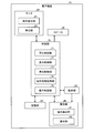
- FIG. 1 is a block diagram showing a configuration example of the electronic device according to the first embodiment.
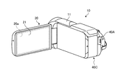
- FIG. 2 is a perspective view of a video camera as an example of the electronic device according to the first embodiment.
- FIG. 3 is a view for explaining an example of the handling instruction moving image of the electronic device according to the first embodiment.
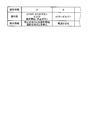
- FIG. 4 is a diagram for explaining an example of operation unit control information of the electronic device according to the first embodiment.
- FIG. 5 is a flowchart illustrating an example of processing performed by the electronic device according to the first embodiment.
- FIG. 6 is a view showing an example of the handling instruction moving image of the electronic device according to the first embodiment.
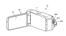
- FIG. 7 is a perspective view showing an example of the operation unit of the electronic device according to the first embodiment.
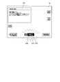
- FIG. 8 is a view showing an example of a display surface on which a handling instruction moving image of the electronic device according to the first embodiment is displayed.
- FIG. 9 is a view showing another example of the handling instruction moving image of the electronic device according to the first embodiment.
- FIG. 10 is a perspective view showing another example of the operation unit of the electronic device according to the first embodiment.
- FIG. 11 is a perspective view showing another example of the operation unit of the electronic device according to the first embodiment.
- FIG. 12 is a perspective view showing another example of the operation unit of the electronic device according to the first embodiment.
- FIG. 13 is a flowchart illustrating an example of processing performed by the electronic device according to the second embodiment.
- FIG. 14 is a block diagram showing a configuration example of the electronic device according to the third embodiment.
- FIG. 1 is a block diagram showing a configuration example of the electronic device according to the first embodiment.
- FIG. 2 is a perspective view of a video camera as an example of the electronic device according to the first embodiment.
- the electronic device 10 is, for example, a video camera, an audio device, a car navigation device, a drive recorder, or the like. In the present embodiment, a video camera will be described as an example of the electronic device 10.
- the electronic device 10 supports the operation according to the reproduction position indicating the position during reproduction when the handling instruction data is reproduced Have.
- the electronic device 10 includes a monitor 20, a speaker 30, an operation unit 40, an operation unit 50, a storage unit 60, and a control unit 70.
- the monitor 20 can display a moving image and various information on the screen 20 a.
- the monitor 20 is a touch panel display and can input various operations.
- the monitor 20 includes, for example, a liquid crystal display (LCD) or an organic electro-luminescence (EL) display.
- the monitor 20 includes an operation detection unit 21 which is a sensor.
- the monitor 20 displays an image based on a control signal from the reproduction control unit 71 of the control unit 70.
- the main body of the monitor 20 opens and closes the housing 11 of the electronic device 10.
- the power of the electronic device 10 is turned on.
- the main unit of the monitor 20 is closed, the power of the electronic device 10 is turned off.
- the main body of the monitor 20 functions in the same manner as the operation unit 40 capable of accepting an operation on the electronic device 10.
- the operation detection unit 21 detects an opening / closing operation of the main body of the monitor 20 with respect to the housing 11 of the electronic device 10.
- the operation detection unit 21 outputs the detected operation information to the control unit 70.
- the light emitting unit 22 is a light emitting element that emits light to indicate the position of the monitor 20.
- the light emitting unit 22 is disposed on the side surface of the main body of the monitor 20.
- the light emitting unit 22 switches on / off in accordance with the operation state of the main body of the monitor 20. Lighting includes blinking.
- the light emitting unit 22 switches on / off when instruction manual data including an operation of the main body of the monitor 20 is displayed on the monitor 20. In the present embodiment, the light emitting unit 22 switches on / off when, for example, the instruction manual moving image 100 described later with reference to FIG. 6 is reproduced, including the operation of the main body of the monitor 20.
- the speaker 30 is an audio output unit.
- the speaker 30 outputs the audio of the video based on the control signal from the reproduction control unit 71 of the control unit 70.
- the operation unit 40 can receive an operation on the electronic device 10.
- the operation unit 40 is provided in the electronic device 10.
- the operation unit 40 is a button for operating the video camera by the user, a switch knob, a dial, or each image displayed on the screen 20 a and operated by the touch panel.
- One or more operation units 40 are disposed in the electronic device 10.
- Each operation unit 40 includes at least one of the operation detection unit 41 and the light emitting unit 42.
- the operation detection unit 41 detects an operation performed by the user on the operation unit 40.
- the operation detection unit 41 outputs the detected operation information to the control unit 70.
- the light emitting unit 42 is a light emitting element that emits light to indicate the position of the operation unit 40.
- the light emitting unit 42 is disposed corresponding to the operation unit 40.
- the arrangement corresponding to the operation unit 40 includes one arranged in the vicinity of the operation unit 40 and one integrally formed with the operation unit 40.
- the light emission unit 42 causes the color or the brightness of the operation unit 40 to be changed so as to be recognized as light emission to indicate the position of the operation unit 40. It is.
- the state in which the image of the operation unit 40 in which the color or the luminance is changed is displayed is included in the state in which the light emitting unit 42 of the operation unit 40 is lit.
- FIG. 7 In addition to FIG. 1 and FIG. 2, using FIG. 7, FIG. 8, FIG. 10, and FIG. Although it demonstrates, the detail is mentioned later.
- the START / STOP button 40A is a button capable of inputting an operation for starting or stopping shooting of a moving image or a still image.
- the START / STOP button 40 ⁇ / b> A is a physical button disposed on the housing 11 of the electronic device 10.
- the START / STOP button 40A is pressed.
- the START / STOP button 40A has an operation detection unit 41A and a light emitting unit 42A.
- the operation detection unit 41A detects an input operation on the START / STOP button 40A. When the operation detection unit 41A detects an input operation, the operation detection unit 41A outputs operation information to the control unit 70 in FIG.
- the light emitting unit 42A is a light emitting element that emits light to indicate the position of the START / STOP button 40A.
- the light emitting unit 42A is integrally formed with the START / STOP button 40A.
- the light emitting unit 42A switches on / off in accordance with the operation state of the START / STOP button 40A.
- the instruction manual data including the operation of the START / STOP button 40A is displayed on the monitor 20, the light emitting unit 42A switches on / off.
- the instruction manual moving image 100 including the operation of the START / STOP button 40A is reproduced, the light emitting unit 42A switches on / off.
- the shooting start / stop button 40B is an image displayed on the screen 20a.
- the shooting start / stop button 40B is a button capable of inputting an operation for starting or stopping shooting of a moving image or a still image.
- the shooting start / stop button 40B is touch-operated.
- the shooting start / stop button 40B includes an operation detection unit 41B and a light emitting unit 42B.
- the operation detection unit 41B detects an input operation on the imaging start / stop button 40B. More specifically, the operation detection unit 41B detects a touch operation on the shooting start / stop button 40B using a sensor.
- the sensor system may be, for example, any known system such as a capacitance system.
- the light emitting unit 42B is an image of the shooting start / stop button 40B in which the color or the luminance is changed so that the light emitting unit 42 visually recognizes as emitting light to indicate the position of the shooting start / stop button 40B.
- the light emitting unit 42B displays / hides the image of the shooting start / stop button 40B whose color or luminance is changed according to the operation state of the shooting start / stop button 40B.
- the light emitting unit 42B switches display / non-display when instruction manual data including an operation of the photographing start / stop button 40B is displayed on the monitor 20 of FIG. In the present embodiment, the light emitting unit 42B switches display / non-display when the instruction manual moving image 100 including the operation of the shooting start / stop button 40B is reproduced.
- the SD card cover 40C will be described with reference to FIG.
- the SD card cover 40C is, for example, a cover disposed so as to be able to open and close with respect to a connection terminal and a storage medium slot including an SD card.
- the SD card cover 40C is opened and closed with respect to the housing 11.
- the SD card cover 40C has an operation detection unit 41C and a light emitting unit 42C.
- the operation detection unit 41C detects an open / close operation on the SD card cover 40C. More specifically, when the SD card cover 40C detects an opening / closing operation, the operation detection unit 41C outputs operation information to the control unit 70 in FIG.
- the light emitting unit 42C is a light emitting element that emits light to indicate the position of the SD card cover 40C.
- the light emitting unit 42C is disposed in the vicinity of the SD card cover 40C.
- the light emitting unit 42C switches on / off according to the open / close state of the SD card cover 40C.
- the light emitting unit 42C switches on / off when instruction manual data including an operation of the SD card cover 40C is displayed on the monitor 20. In the present embodiment, when the instruction manual moving image 100 including the operation of the SD card cover 40C is reproduced, the light emitting unit 42C switches on / off.
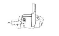
- the SD card slot 40D will be described with reference to FIG.
- the SD card slot 40D is a slot to which an SD card can be attached and detached. An SD card is inserted into and removed from the SD card slot 40D.
- the SD card slot 40D has an operation detection unit 41D and a light emitting unit 42D.
- the operation detection unit 41D detects the insertion / removal operation of the SD card with respect to the SD card slot 40D. More specifically, the operation detection unit 41D outputs operation information to the control unit 70 shown in FIG. 1 when detecting the insertion / removal operation of the SD card with respect to the SD card slot 40D.
- the light emitting unit 42D is a light emitting element that emits light to indicate the position of the SD card slot 40D.
- the light emitting unit 42D is disposed in the vicinity of the SD card slot 40D.
- the light emitting unit 42D switches on / off according to the insertion / removal state of the SD card to the SD card slot 40D.
- the light emitting unit 42D switches on / off when instruction manual data including an operation of the SD card slot 40D is displayed on the monitor 20. In the present embodiment, the light emitting unit 42D switches on / off when the instruction manual moving image 100 including the operation of the SD card slot 40D is reproduced.
- the operating unit 50 operates based on the operation performed on the operating unit 40.
- the operation unit 50 is an imaging unit that operates by an operation on the START / STOP button 40A or the imaging start / stop button 40B.
- the operation unit 50 is a reading unit that operates by the operation of inserting and removing the SD card into and from the SD card slot 40D.
- the operating unit 50 is a power supply unit that operates by opening and closing the main body of the monitor 20.
- the storage unit 60 is used, for example, for temporary storage of data in the electronic device 10.
- the storage unit 60 is, for example, a semiconductor memory device such as a random access memory (RAM), a read only memory (ROM), a flash memory, or a storage device such as a hard disk or an optical disk. Alternatively, it may be an external storage device wirelessly connected via a communication device (not shown).
- the storage unit 60 is associated with the handling instruction data and the reproduction position of the handling instruction data, and operation unit control information indicating control information of the main body of the monitor 20 and the operation unit 40 which is the operation target described in the handling instruction data. And remember.
- the instruction manual data describes an operation method when the user operates the electronic device 10.
- the instruction manual data includes, for each operation, an operation target to be operated by the user and an operation method for explaining how to operate the operation target.
- the handling instruction data has, as one of metadata, identification information for referring to the operation unit control information related to the operation target.
- the instruction manual data includes, for example, a moving image representing a printed instruction manual by a moving image, an image including data of a web page for publishing the printed instruction manual, and the printed instruction manual electronically. Including saved electronic files.
- the handling instruction data is described as a handling instruction moving image 100.
- the instruction manual moving image 100 is one or more moving images explaining the handling of the electronic device 10. More specifically, the handling instruction moving image 100 includes, for each operation, a main body and an operation unit 40 of the monitor 20 which is an operation target to be operated by the user, and an operation method for explaining how to operate the operation target. Including. For example, the instruction manual moving image 100 for the “power on” operation of the electronic device 10 will be described as pressing the power button as the operation unit 40.
- the operation instruction control information is associated with the instruction manual moving image 100. More specifically, in the instruction manual moving image 100, identification information for identifying operation unit control information is associated with a reproduction position where an operation of the operation unit 40 by the user is required. A plurality of operation unit control information may be associated with one handling instruction moving image 100.
- the playback position of the instruction manual moving image 100 is, for example, chapter information indicating a break of the instruction manual moving image 100, stamp information indicating a predetermined position of the instruction manual moving image 100, or a time indicating a reproduction time from the start of reproduction of the instruction manual moving image 100. It is information.
- FIG. 3 is a view for explaining an example of the handling instruction moving image of the electronic device according to the first embodiment.
- the instruction manual moving image 100 includes a plurality of moving images.
- a moving image i1 which is one of the instruction manual moving image 100, includes identification information "A" of the operation unit control information in the metadata.
- the moving image i2 and the moving image i4, which are one of the instruction manual moving image 100, do not include identification information of operation unit control information in the metadata.
- the operation unit control information is control information of the operation target described in the instruction manual moving image 100.
- the operation unit control information stores an operation target and operation information for each identification information that identifies the operation unit control information. More specifically, the operation unit control information stores an operation target and operation information of the operation unit 50 that operates by an operation on the operation target.
- the operation unit control information includes control information for outputting a control signal to cause the light emitting unit as the operation target to emit light when the reproduction position of the handling instruction moving image 100 becomes a predetermined position.
- the operation unit control information also includes control information for outputting a control signal to the operation unit 50 operated by the operation when the operation on the operation target is performed.
- FIG. 4 is a diagram for explaining an example of operation unit control information of the electronic device according to the first embodiment.
- the operation unit 40 of the operation target is the START / STOP button 40A or the shooting start / stop button 40B, and the operation information is "shooting start when stopped", "shooting state" When it is "stop”.
- the operation unit control information of the identification information B is that the operation unit 40 to be operated is the SD card cover 40C and the operation information is "turn off the power”.
- control unit 70 the reproduction control unit 71, the display control unit 72, the light emission control unit 73, the operation information acquisition unit 74, and the operation control unit 75 will be described.
- the control unit 70 controls the monitor 20, the speaker 30, the operation unit 40, the operation unit 50, and the storage unit 60. More specifically, the control unit 70 performs playback control of the instruction manual moving image 100. Then, the control unit 70 controls the light emission of the light emitting unit 22 of the main body of the monitor 20 or the light emitting unit 42 of each operation unit 40 described in the instruction manual moving image 100 being reproduced. Then, the control unit 70 controls the operation of the operation unit 50 in accordance with an operation on the main body of the monitor 20 or each operation unit 40.
- the control unit 70 is, for example, an arithmetic processing unit (control unit) configured of a CPU (Central Processing Unit), a processor for video processing, and the like.
- the control unit 70 loads the program stored in the storage unit 60 into the memory and executes an instruction included in the program.
- the control unit 70 may be configured of one or more devices.
- the control unit 70 includes a reproduction control unit 71, a display control unit 72, a light emission control unit 73, an operation information acquisition unit 74, and an operation control unit 75.
- the reproduction control unit 71 controls reproduction of the instruction manual moving image 100. More specifically, the reproduction control unit 71 outputs a control signal for executing the display of the instruction manual moving image 100 on the monitor 20 and the output of the audio of the instruction manual moving image 100 on the speaker 30.
- the reproduction control unit 71 acquires, from the storage unit 60, the instruction manual moving image 100 selected based on the user's operation, displays the moving image on the monitor 20, and outputs the sound from the speaker 30.
- the reproduction control unit 71 displays the instruction explanation moving image 100 related to the operated operation unit 40 on the monitor 20. Good.
- the reproduction control unit 71 may display the thumbnails of each moving image on the monitor 20 as a list when there are a plurality of instruction manual moving images 100 related to the operation unit 40.
- the display control unit 72 outputs a video signal for displaying the instruction manual moving image 100 on the monitor 20 or stops the output based on the control by the reproduction control unit 71.
- the display control unit 72 can always obtain the reproduction position indicating the position during reproduction of the instruction manual moving image 100.
- the display control unit 72 can always obtain the reproduction position of the instruction manual moving image 100 reproduced on the monitor 20.
- the display control unit 72 outputs the reproduction position of the acquired instruction manual moving image 100 to the light emission control unit 73.
- the display control unit 72 changes the display mode of the instruction manual moving image 100 on the screen 20a when the image of the operation target is lit, and the image of the operation target On the front. More specifically, the display control unit 72 may reduce the display range on the screen 20a of the instruction manual moving image 100 and may display the image of the operation target on the front of the screen 20a when lighting the image of the operation target. When lighting the image of the operation target, the display control unit 72 may make the handling instruction moving image 100 semi-transparent and display the image of the operation target on the front of the screen 20a. When lighting the image of the operation target, the display control unit 72 may shift the display position on the screen 20 a of the handling instruction moving image 100 to display the image of the operation target on the front of the screen 20 a.
- the light emission control unit 73 causes the light emitting unit disposed in the vicinity of the main body of the monitor 20 or the operation unit 40 which is the operation target described in the instruction manual moving image 100 displayed on the monitor 20 to emit light.
- the light emission control unit 73 outputs a control signal for controlling on / off of the light emitting unit 22 of the main body of the monitor 20 or the light emitting unit 42 of the operation unit 40. More specifically, the light emission control unit 73 displays the light emission control unit 73 on the monitor 20 based on the reproduction position acquired by the display control unit 72 and the operation unit control information associated with the reproduction position at the time of reproduction of the instruction manual moving image 100.
- the light emitting unit 22 of the main body of the monitor 20 or the light emitting unit 42 of the operation unit 40 described in the instruction manual moving image 100 is turned on.
- the operation information acquisition unit 74 operates the user on the main unit of the monitor 20 or the operation unit 40 to be operated.
- the light emitting unit 22 of the main body of the monitor 20 or the light emitting unit 42 of the operation unit 40 is turned off.
- the light emission control unit 73 displays the image of the operation unit 40 in which the color or the luminance is changed. After the light emission control unit 73 displays the image of the operation unit 40 in which the color or the luminance is changed, when the user's operation on the image of the operation unit 40 is detected by the operation information acquisition unit 74, the normal state is not lit The image of the operation unit 40 is displayed.
- the operation information acquisition unit 74 acquires operation information detected by the operation detection unit 21 of the main body of the monitor 20 or the operation detection unit 41 of the operation unit 40. More specifically, the operation information acquisition unit 74 acquires operation information related to the user's operation on the main body of the monitor 20 or the operation unit 40. The operation information acquisition unit 74 outputs the acquired operation information to the operation control unit 75.
- Operation control unit 75 controls the operation of target operation unit 50 when the user's operation on the main unit of monitor 20 or operation unit 40 is detected based on the operation information acquired by operation information acquisition unit 74.
- FIG. 5 is a flowchart illustrating an example of processing performed by the electronic device according to the first embodiment.
- the user performs a reproduction start operation of the instruction manual moving image 100. More specifically, for example, the user selects an item that the user wants to confirm the content from among the items displayed on the menu screen.
- the menu screen displays items for the operation of the electronic device 10 which is a video camera.
- the items are operations such as "turn on power”, “take a video”, and "insert SD card”.
- the electronic device 10 When the user selects an item to be confirmed from the instruction manual moving image 100 and performs a reproduction start operation, the electronic device 10 reproduces the instruction manual moving image 100 corresponding to the selected item (step S11). More specifically, the electronic device 10 causes the reproduction control unit 71 to output a control signal for reproducing the instruction manual moving image 100 corresponding to the selected item. The electronic device 10 causes the display control unit 72 to output a video signal for displaying the handling instruction moving image 100 on the monitor 20. The electronic device 10 proceeds to step S12.
- the electronic device 10 determines whether the reproduction position of the handling instruction moving image 100 has reached the position at which the operation target is lit (step S12). More specifically, the electronic device 10 detects the reproduction position of the instruction manual moving image 100 by the reproduction control unit 71, and the reproduction position of the instruction manual moving image 100 has reached a position to light the main body of the monitor 20 or the operation unit 40 In other words, it is determined whether the position where the operation unit control information is associated has been reached. When it is determined that the electronic device 10 has reached the position associated with the operation unit control information, the electronic device 10 determines that the reproduction position of the instruction manual moving image 100 has reached the position for lighting the main unit of the monitor 20 or the operation unit 40. (Yes in step S12), the process proceeds to step S13.
- step S12 If it is determined that the electronic device 10 has not reached the position associated with the operation unit control information, the reproduction position of the instruction manual moving image 100 has not reached the position for lighting the main unit of the monitor 20 or the operation unit 40. It determines with (No in step S12), and performs the process of step S12 again.
- the electronic device 10 lights the operation target (step S13). More specifically, the electronic device 10 causes the light emission control unit 73 to light the light emitting unit 22 of the main body of the monitor 20 or the light emitting unit 42 of the operation unit 40 based on the operation unit control information. The electronic device 10 proceeds to step S14.
- the electronic device 10 determines whether there is an input to the operation target (step S14). More specifically, the electronic device 10 detects the presence or absence of an input to the main body of the monitor 20 or the operation unit 40 by the operation information acquisition unit 74. When the operation information acquisition unit 74 detects an input to the main body of the monitor 20 or the operation unit 40 (Yes in step S14), the electronic device 10 proceeds to step S15. When the operation information acquisition unit 74 does not detect an input to the main body of the monitor 20 or the operation unit 40 (No in step S14), the electronic device 10 repeats the process of step S14.
- the electronic device 10 executes an operation (step S15). More specifically, the electronic device 10 causes the operation control unit 75 to execute the operation of the operation unit 50 in response to the input to the main body of the monitor 20 or the operation unit 40. The electronic device 10 proceeds to step S16.
- the electronic device 10 ends the reproduction of the instruction manual moving image 100 (step S16). More specifically, the electronic device 10 ends the reproduction of the instruction manual moving image 100 by the reproduction control unit 71. The electronic device 10 ends the process.
- the electronic device 10 performs the process from step S11 to step S15 and the operation unit control information until the reproduction of the instruction instruction moving image 100 ends. Repeat as many times as you like.
- FIG. 6 is a view showing an example of the handling instruction moving image of the electronic device according to the first embodiment.
- FIG. 7 is a perspective view showing an example of the operation unit of the electronic device according to the first embodiment.
- FIG. 8 is a view showing an example of a display surface on which a handling instruction moving image of the electronic device according to the first embodiment is displayed.
- the electronic device 10 causes the reproduction control unit 71 to display an instruction manual moving image 100 describing an operation for taking a moving image on the monitor 20, and outputs the sound of the instruction manual moving image 100 by the speaker 30.
- the reproduction position of the instruction manual moving image 100 is a position at which the moving image shown in FIG. 6 is displayed on the monitor 20, the associated operation unit control information exists.
- the electronic device 10 causes the light emission control unit 73 to start START, which is the operation unit 40, based on the operation unit control information.
- start START which is the operation unit 40
- the light emitting unit 42A of the / STOP button 40A and the light emitting unit 42B of the shooting start / stop button 40B are turned on.
- the display control unit 72 reduces the display range of the instruction manual moving image 100 on the screen 20a, and the shooting start / stop button 40B and the light emission The section 42B is displayed on the front of the screen 20a.
- the user confirms that the light emitting unit 42A and the light emitting unit 42B are turned on, so that the user can operate the imaging start / stop button 40B displayed on the START / STOP button 40A or the screen 20a.
- the user presses the START / STOP button 40A or touches the shooting start / stop button 40B.
- the electronic device 10 detects that the operation has been input to the START / STOP button 40A or the imaging start / stop button 40B displayed on the screen 20a by the operation detection unit 41A or the operation detection unit 41B.
- the operation information acquisition unit 74 acquires operation information.
- the electronic device 10 causes the operation control unit 75 to output a control signal for starting imaging to the imaging unit.
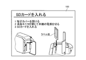
- FIG. 9 is a view showing another example of the handling instruction moving image of the electronic device according to the first embodiment.
- FIG. 10 is a perspective view showing another example of the operation unit of the electronic device according to the first embodiment.
- FIG. 11 is a perspective view showing another example of the operation unit of the electronic device according to the first embodiment.
- FIG. 12 is a perspective view showing another example of the operation unit of the electronic device according to the first embodiment.
- the electronic device 10 causes the reproduction control unit 71 to display the instruction manual moving image 100 describing the operation of inserting the SD card on the monitor 20, and outputs the sound of the instruction manual moving image 100 by the speaker 30.
- Three operation unit control information is associated with the instruction manual moving image 100. More specifically, when the playback position of the instruction manual moving image 100 is a position at which the sound “1 SD card cover is opened” is reproduced while the moving image shown in FIG. 9 is displayed on the monitor 20, “2 Control panel control information associated with the position where the sound to close the liquid crystal monitor and the power of the device is turned off is played back, and the sound to "3 Insert SD card” is played back Each exists.
- the electronic device 10 is based on the operation unit control information.
- the light emission control unit 73 turns on the light emission unit 42C of the SD card cover 40C that is the operation unit 40.
- the user confirms that it is sufficient to operate the SD card cover 40C because the light emitting unit 42C of the SD card cover 40C is on.
- the user opens the SD card cover 40C.
- the electronic device 10 reproduces the sound “2 close the liquid crystal monitor and turn off the power of this machine”.
- the light emission control unit 73 turns on the light emission unit 22 of the main body of the monitor 20 which is the operation unit 40 based on the operation unit control information.
- the user confirms that it is sufficient to operate the main body of the monitor 20 because the light emitting unit 22 of the main body of the monitor 20 is on.
- the user closes the main body of the monitor 20.
- the electronic device 10 detects that the closing operation of the monitor 20 is performed by the operation detection unit 21.
- the operation information acquisition unit 74 acquires operation information.
- the electronic device 10 causes the operation control unit 75 to output a control signal to turn off the power of the electronic device 10.
- the electronic device 10 is based on the operation unit control information.
- the light emission control unit 73 turns on the light emitting unit 42D of the SD card slot 40D that is the operation unit 40.
- the user confirms that it is sufficient to operate the SD card slot 40D because the light emitting unit 42D of the SD card slot 40D is on.
- the user inserts an SD card into the SD card slot 40D.
- the electronic device 10 detects that the SD card is inserted into the SD card slot 40D by the operation detection unit 41D.
- the operation information acquisition unit 74 acquires operation information.
- the electronic device 10 causes the operation control unit 75 to output a control signal for reading the SD card to the reading unit.
- the electronic device 10 controls the light emission of the light emitting unit 22 of the main body of the monitor 20 or the light emitting unit 42 of each operation unit 40 described in the instruction manual moving image 100 being reproduced.
- the electronic device 10 controls the operation of the operation unit 50 in accordance with an operation on the main body of the monitor 20 or each operation unit 40.
- the operation unit 40 is operated in a state where the handling instruction moving image 100 is not reproduced on the monitor 20.
- the “description mode” is set in advance, or the operation on the operation unit 40 is changed to a long press different from the normal operation.
- the user operates the operation unit 40 in a state where the instruction manual moving image 100 is not reproduced on the monitor 20.
- the reproduction control unit 71 Since the user operates the operation unit 40 in a state where the instruction manual moving image 100 is not reproduced, the reproduction control unit 71 displays the instruction manual moving image 100 related to the operated operation unit 40 on the monitor 20. When there are a plurality of instruction manual moving images 100 related to the operation unit 40, the reproduction control unit 71 may display thumbnails of each moving image on the monitor 20 as a list.
- the electronic device 10 displays the handling instruction moving image 100 related to the operated operation unit 40 on the monitor 20. .
- the handling instruction moving image 100 and the operation target for performing the operation corresponding to the handling instruction moving image 100 are associated and stored.
- the light emitting unit 22 of the main unit of the monitor 20 or the light emitting unit 42 of the operation unit 40 described in the instruction instruction moving image 100 is lit.
- the light emitting unit 22 of the main body of the monitor 20 or the light emitting unit 42 of the operation unit 40 is turned on in accordance with the reproduction position of the handling instruction moving image 100.
- the handling instruction moving image 100 related to the operated operation unit 40 is displayed on the monitor 20.
- the user can easily confirm the operation that can be performed by the operation unit 40 by the instruction manual moving image 100. Compared with searching for an operation related to the operation unit 40 in the conventional printed instruction manual, confirmation of the operation can be facilitated.
- the operation of the electronic device 10 can be described more easily.
- the present embodiment can more appropriately support the operation of the electronic device 10.
- operability can be improved.
- FIG. 13 is a flowchart illustrating an example of processing performed by the electronic device according to the second embodiment.
- the electronic device 10 has the same basic configuration as the electronic device 10 of the first embodiment. In the following description, the same reference numerals or the corresponding reference numerals are given to the same constituent elements as the electronic device 10, and the detailed description thereof is omitted.
- the electronic device 10 of the present embodiment differs from the first embodiment in the processing in the control unit 70.
- the reproduction control unit 71 When a jump operation is performed to move to an instruction manual moving image 100 different from the instruction manual moving image 100 being reproduced, the reproduction control unit 71 reproduces the instruction manual moving image 100 of the jump destination as the movement destination. More specifically, when the reproduction control unit 71 detects that the instruction manual moving image 100 is jumped, the reproduction control unit 71 outputs a control signal for reproducing the instruction instruction moving image 100 as the jump destination.
- the jump operation means, for example, a fast forward operation or a jump operation.
- the display control unit 72 detects that the instruction manual moving image 100 is jumped by the operation of the user during the reproduction of the instruction manual moving image 100.
- the display control unit 72 outputs a video signal for displaying the instruction manual moving image 100 of the jump destination on the monitor 20 based on the control by the reproduction control unit 71 during the reproduction of the instruction manual moving image 100.
- step S21 and steps S23 to S27 of the flowchart shown in FIG. 13 perform the same processes as the processes of step S11 and steps S12 to S16 of the flowchart shown in FIG.
- the electronic device 10 determines whether a jump operation has been performed during the reproduction of the handling instruction moving image 100 (step S22). More specifically, when the reproduction control unit 71 detects a jump operation (Yes in step S22), the electronic device 10 proceeds to step S28. When the reproduction control unit 71 does not detect a jump operation (No in step S22), the electronic device 10 proceeds to step S23.
- the electronic device 10 When the user performs a jump operation during reproduction of the instruction manual moving image 100 (Yes in step S22), the electronic device 10 reproduces the instruction manual moving image 100 at the jump destination (step S28). More specifically, the electronic device 10 causes the reproduction control unit 71 to output a control signal for reproducing the instruction manual moving image 100 at the jump destination. The electronic device 10 causes the display control unit 72 to output, on the monitor 20, a video signal for displaying the instruction manual moving image 100 of the jump destination. The electronic device 10 proceeds to step S29.
- the electronic device 10 determines whether the reproduction position of the handling instruction moving image 100 at the jump destination has reached the position at which the operation target is to be lit (step S29). When it is determined that the electronic device 10 has reached the position associated with the operation unit control information, the reproduction position of the instruction manual moving image 100 at the jump destination has reached the position at which the main unit of the monitor 20 or the operation unit 40 is lit. The determination is made (Yes in step S29), and the process proceeds to step S30. When it is determined that the electronic device 10 has not reached the position associated with the operation unit control information, the reproduction position of the instruction manual moving image 100 at the jump destination reaches the position at which the main unit of the monitor 20 or the operation unit 40 is lit. It determines with not having carried out (it is No at step S29), and performs processing of step S29 again.
- the electronic device 10 lights the operation target of the jump destination (step S30). More specifically, the electronic device 10 causes the light emission control unit 73 to light the light emitting unit 22 of the main body of the monitor 20 or the light emitting unit 42 of the operation unit 40 based on the operation unit control information. The electronic device 10 proceeds to step S31.
- the electronic device 10 determines whether there is an input to the operation target of the jump destination (step S31).
- the operation information acquisition unit 74 detects an input to the main body of the monitor 20 or the operation unit 40 (Yes in step S31)
- the electronic device 10 proceeds to step S32.
- the operation information acquisition unit 74 does not detect an input to the main body of the monitor 20 or the operation unit 40 (No in step S31)
- the electronic device 10 repeats the process of step S31.
- the electronic device 10 executes the operation of the jump destination (step S32). More specifically, the electronic device 10 causes the operation control unit 75 to execute the operation of the operation unit 50 in response to the input to the main body of the monitor 20 or the operation unit 40. The electronic device 10 proceeds to step S33.
- the electronic device 10 ends the reproduction of the instruction manual 100 as the jump destination (step S33). More specifically, the electronic device 10 ends the reproduction of the instruction manual moving image 100 by the reproduction control unit 71. The electronic device 10 ends the process.
- the instruction manual moving image 100 of the jump destination is reproduced, and when the reproduction position becomes a predetermined position, the instruction manual moving image of the jump destination
- the light emitting unit 22 of the main body of the monitor 20 or the light emitting unit 42 of the operation unit 40 described in 100 is turned on.
- the light emitting unit 22 of the main body of the monitor 20 or the light emitting unit 42 of the operation unit 40 is turned on in accordance with the reproduction position of the handling instruction moving image 100 at the jump destination.
- FIG. 14 is a block diagram showing a configuration example of the electronic device according to the third embodiment.
- the display device 200 for reproducing the handling instruction moving image 100 and the electronic device 300 are configured as independent devices.
- the display device 200 mainly performs various controls on the monitor 210 having the function of the monitor 20 of the first embodiment, the speaker 220 having the function of the speaker 30, the storage unit 230 having the function of the storage unit 60, and the like.
- the control unit 240 is included.
- the control unit 240 includes a reproduction control unit 241, a display control unit 242, and a control signal output unit 243.
- the reproduction control unit 241 has the same function as the reproduction control unit 71.
- the display control unit 242 has the same function as the display control unit 72.
- the control signal output unit 243 has the same function as the light emission control unit 73.
- control signal output unit 243 emits light from the light emitting unit 22 or the operation unit 40 of the main body of the monitor 20 described in the instruction manual moving image 100 based on the operation unit control information when reproducing the instruction manual moving image 100.
- a control signal to light the unit 42 is output to the electronic device 300.
- the electronic device 300 includes an operation unit 310 configured in the same manner as the operation unit 40, an operation unit 320 configured in the same manner as the operation unit 50, and a control unit 330 that performs various controls on them.
- the control unit 330 includes a control signal acquisition unit 331, a light emission control unit 332, an operation information acquisition unit 333, and an operation control unit 334.
- the control signal acquisition unit 331 acquires a control signal from the display device 200.
- the light emission control unit 332 has a function corresponding to the light emission control unit 73.
- the operation information acquisition unit 333 has a function corresponding to the operation information acquisition unit 74.
- the operation control unit 334 has a function corresponding to the operation control unit 75.
- the electronic device 300 that does not have a monitor that displays information uses the display device 200 that has a monitor including a mobile communication terminal or a computer, for example. We can support the operation appropriately.
- Each component of the illustrated electronic device 10 is functionally conceptual and may not necessarily be physically configured as illustrated. That is, the specific form of each device is not limited to the illustrated one, and all or a part thereof is functionally or physically dispersed or integrated in an arbitrary unit according to the processing load and use condition of each device, etc. May be
- the configuration of the electronic device 10 is realized by, for example, a program loaded into a memory as software.
- the above embodiment has been described as a functional block realized by cooperation of these hardware or software. That is, these functional blocks can be realized in various forms by hardware only, software only, or a combination thereof.
- the electronic device 10 turns on the light emitting unit 22 of the main body of the monitor 20 or the light emitting unit 42 of the operation unit 40 described in the instruction manual moving image 100 and, for example, a moving mechanism for moving the operation unit 40 or the operation unit 40
- the control unit 70 may have an operation control unit (not shown) that drives the drive. More specifically, for example, when the instruction manual moving image 100 for explaining an operation for inserting an SD card shown in FIG. 9 is reproduced, the light emission control unit 73 turns on the light emitting unit 42C of the SD card cover 40C and performs operation control. The unit drives the moving mechanism of the SD card cover 40C to open the SD card cover 40C.
- the operation control unit when attention is required. By doing this, it is possible to support the operation more appropriately.
- the instruction manual data is described as the instruction manual moving image 100, but is not limited thereto.
- the instruction manual data may be a web page or an electronic file in which the instruction manual is published as an image on a homepage or the like.
- the display control unit 72 sets the color of the character string indicating the operation unit 40 to be operated on the corresponding page of the instruction manual data. You may change it.
- the color of the character string indicating the operation target 40 is changed according to the order of the operations, and when the operation is completed, the next operation target is displayed.
- the color of the character string indicating the operation unit 40 is changed.
- the description in the instruction manual moving image 100 displayed on the monitor 20 is detailed or simplified You may change the size of the Furthermore, depending on the user attribute, as described above, the light emitting unit 22 of the main body of the monitor 20 or the light emitting unit 42 of the operation unit 40 may be turned on and the operation control unit may operate the operation unit 40. In this way, the operation can be supported more appropriately in accordance with the user's attributes.
- the operation unit 40 may vibrate.
- the operation unit 40 may have a vibrating unit (not shown) instead of the light emitting unit 42.
- the vibration unit is, for example, a vibration motor or a diaphragm.
- the speaker 30 may emit sound when the reproduction position is at a predetermined position.
- a voice including the position of the operation unit 40 may be issued, such as "Please press the button on the right" so that the position of the operation unit 40 can be grasped.
Landscapes
- Engineering & Computer Science (AREA)
- General Engineering & Computer Science (AREA)
- Theoretical Computer Science (AREA)
- Human Computer Interaction (AREA)
- Physics & Mathematics (AREA)
- General Physics & Mathematics (AREA)
- User Interface Of Digital Computer (AREA)
- Input From Keyboards Or The Like (AREA)
Abstract
操作を受付可能な操作部40と、操作部40に対応して配置され、操作部40の位置を知らせる発光部42と、モニタ20に表示している電子機器10の取り扱いを説明する取扱説明データにおいて説明している操作部40に対応して配置された発光部42を発光させる発光制御部73、を備えることを特徴とする。
Description
本出願は、電子機器、操作支援方法及びプログラムに関する。
電子機器は、多くの機能を有している。そこで、ユーザの操作を支援するために、印刷された取扱説明書またはインターネット上に公開された取扱説明ページによって、取り扱い説明が提供される。
音響装置の動作モード及び動作状態を視覚に直感的に把握できるようにする技術が知られている(例えば、特許文献1参照)。この技術は、カーオーディオ装置等の音響装置の操作キーに設けられているキー照明素子を音響装置の動作状態に合わせて、点灯/消灯状態を変化させる。操作キーを操作する際に、現時点で操作が有効となっているか無効となっているかをわかるようにしたDVDプレーヤーに関する技術が知られている(例えば、特許文献2参照)。
しかしながら、印刷された取扱説明書は、ページ数が多かったり、文字が小さかったりすることがある。インターネット上に公開された取扱説明ページは、複数ページに亘る記載を参照しながら電子機器を操作しなくてはならない。印刷された取扱説明書またはインターネット上に公開された取扱説明ページは、可読性が悪かったり、知りたい情報を見つけにくかったりすることがある。このように、電子機器は、操作性について改善の余地があった。
本発明は、上記に鑑みてなされたものであって、操作性のよい電子機器、操作支援方法及びプログラムを提供することを目的とする。
上述した課題を解決し、目的を達成するために、本発明に係る電子機器は、操作を受付可能な操作部と、前記操作部に対応して配置され、前記操作部の位置を知らせる発光部と、表示部に表示している電子機器の取り扱いを説明する取扱説明データにおいて説明している前記操作部に対応して配置された前記発光部を発光させる発光制御部と、を備えることを特徴とする。
本発明に係る操作支援方法は、操作を受付可能な操作部と、前記操作部に対応して配置され、前記操作部の位置を知らせる発光部と、を有する電子機器の操作支援方法であって、表示部に表示している電子機器の取り扱いを説明する取扱説明データにおいて説明している前記操作部に対応して配置された前記発光部を発光させる発光制御ステップ、を含むことを特徴とする。
本発明に係るプログラムは、操作を受付可能な操作部と、前記操作部に対応して配置され、前記操作部の位置を知らせる発光部と、を有する電子機器として動作するコンピュータに実行させるためのプログラムであって、表示部に表示している電子機器の取り扱いを説明する取扱説明データにおいて説明している前記操作部に対応して配置された前記発光部を発光させる発光制御ステップを電子機器として動作するコンピュータに実行させる。
本発明によれば、操作性のよい電子機器、操作支援方法及びプログラムを提供することができるという効果を奏する。
以下に添付図面を参照して、本発明に係る電子機器、操作支援方法及びプログラムの実施形態を詳細に説明する。なお、以下の実施形態により本発明が限定されるものではない。
[第一実施形態]
図1は、第一実施形態に係る電子機器の構成例を示すブロック図である。図2は、第一実施形態に係る電子機器の一例としてビデオカメラの斜視図である。電子機器10は、例えば、ビデオカメラ、オーディオ機器、カーナビゲーション装置、ドライブレコーダなどである。本実施形態では、電子機器10の一例として、ビデオカメラについて説明する。電子機器10は、ユーザが取扱説明データによって電子機器10の取り扱いを確認する際に、取扱説明データが再生されている際の、再生中の位置を示す再生位置に応じて、操作を支援する機能を有する。電子機器10は、モニタ20と、スピーカ30と、操作部40と、動作部50と、記憶部60と、制御部70とを備える。
図1は、第一実施形態に係る電子機器の構成例を示すブロック図である。図2は、第一実施形態に係る電子機器の一例としてビデオカメラの斜視図である。電子機器10は、例えば、ビデオカメラ、オーディオ機器、カーナビゲーション装置、ドライブレコーダなどである。本実施形態では、電子機器10の一例として、ビデオカメラについて説明する。電子機器10は、ユーザが取扱説明データによって電子機器10の取り扱いを確認する際に、取扱説明データが再生されている際の、再生中の位置を示す再生位置に応じて、操作を支援する機能を有する。電子機器10は、モニタ20と、スピーカ30と、操作部40と、動作部50と、記憶部60と、制御部70とを備える。
モニタ20は、動画および各種情報を画面20aに表示可能である。モニタ20は、タッチパネル式ディスプレイであり、各種操作を入力可能である。モニタ20は、例えば、液晶ディスプレイ(LCD:Liquid Crystal Display)または有機EL(Organic Electro-Luminescence)ディスプレイなどを含む。モニタ20は、センサである操作検出部21を含む。モニタ20は、制御部70の再生制御部71からの制御信号に基づいて、映像を表示する。
本実施形態において、モニタ20の本体は、電子機器10の筐体11に対して開閉操作する。モニタ20の本体を開操作すると、電子機器10の電源を入れる。モニタ20の本体を閉操作すると、電子機器10の電源を切る。このように、本実施形態において、モニタ20の本体は、電子機器10に対する操作を受付可能な操作部40と同様に機能する。
操作検出部21は、モニタ20の本体の、電子機器10の筐体11に対する開閉操作を検出する。操作検出部21は、検出した操作情報を制御部70に出力する。
発光部22は、モニタ20の位置を知らせるために発光する発光素子である。発光部22は、モニタ20の本体の側面に配置されている。発光部22は、モニタ20の本体の動作状態に合わせて点灯/消灯を切り替える。点灯には、点滅を含む。発光部22は、モニタ20の本体の操作を含む取扱説明データがモニタ20に表示されるとき、点灯/消灯を切り替える。本実施形態では、発光部22は、モニタ20の本体の操作を含む、例えば、図6を用いて後述する取扱説明動画100が再生されるとき、点灯/消灯を切り替える。
スピーカ30は、音声出力部である。スピーカ30は、制御部70の再生制御部71からの制御信号に基づいて、映像の音声を出力する。
操作部40は、電子機器10に対する操作を受付可能である。操作部40は、電子機器10に設けられている。操作部40は、ユーザがビデオカメラを操作するボタン、スイッチノブ、ダイヤル、または、画面20aに表示されタッチパネルによって操作する各画像である。操作部40は、電子機器10に一つ以上配置される。各操作部40は、操作検出部41と発光部42との少なくともいずれかを有する。
操作検出部41は、操作部40に対してユーザが行った操作を検出する。操作検出部41は、検出した操作情報を制御部70に出力する。
発光部42は、操作部40の位置を知らせるために発光する発光素子である。発光部42は、操作部40に対応して配置されている。操作部40に対応して配置されているとは、操作部40の近傍に配置されているものと、操作部40と一体に形成されているものとを含む。
または、発光部42は、操作部40が画面20aに表示された画像である場合、操作部40の位置を知らせるために発光したように視認させる、色または輝度を変化させた操作部40の画像である。ここでは、色または輝度を変化させた操作部40の画像を表示している状態を、当該操作部40の発光部42が点灯しているという状態に含める。
ここで、図1、図2以外にも、図7、図8、図10、図12を用いて、本実施形態の一部を構成する操作部40、SDカードカバー40C、SDカードスロット40Dについて説明するが、詳細は後述する。
図7を用いて、本実施形態における操作部40の例を説明する。START/STOPボタン40Aは、動画または静止画の撮影を開始または停止するための操作を入力可能なボタンである。START/STOPボタン40Aは、電子機器10の筐体11に配置された物理ボタンである。START/STOPボタン40Aは、押下操作される。START/STOPボタン40Aは、操作検出部41Aと発光部42Aとを有する。
操作検出部41Aは、START/STOPボタン40Aに対する入力操作を検出する。操作検出部41Aは、入力操作を検出すると、操作情報を図1の制御部70に出力する。
発光部42Aは、START/STOPボタン40Aの位置を知らせるために発光する発光素子である。発光部42Aは、START/STOPボタン40Aと一体に形成されている。発光部42Aは、START/STOPボタン40Aの動作状態に合わせて点灯/消灯を切り替える。発光部42Aは、START/STOPボタン40Aの操作を含む取扱説明データがモニタ20に表示されるとき、点灯/消灯を切り替える。本実施形態では、発光部42Aは、START/STOPボタン40Aの操作を含む取扱説明動画100が再生されるとき、点灯/消灯を切り替える。
また図8を用いて、画面20aに表示された画像が操作部40として機能している状態を説明する。撮影開始/停止ボタン40Bは、画面20aに表示された画像である。撮影開始/停止ボタン40Bは、動画または静止画の撮影を開始または停止するための操作を入力可能なボタンである。撮影開始/停止ボタン40Bは、タッチ操作される。撮影開始/停止ボタン40Bは、操作検出部41Bと発光部42Bとを有する。
操作検出部41Bは、撮影開始/停止ボタン40Bに対する入力操作を検出する。より詳しくは、操作検出部41Bは、撮影開始/停止ボタン40Bに対するタッチ操作をセンサによって検出する。センサの方式は、例えば、静電容量方式などの公知のいずれの方式でもよい。操作検出部41Bは、入力操作を検出すると、操作情報を図1の制御部70に出力する。
発光部42Bは、撮影開始/停止ボタン40Bの位置を知らせるために発光したように視認させる、色または輝度を変化させた撮影開始/停止ボタン40Bの画像である。発光部42Bは、撮影開始/停止ボタン40Bの動作状態に合わせて、色または輝度を変化させた撮影開始/停止ボタン40Bの画像を表示/非表示にする。発光部42Bは、撮影開始/停止ボタン40Bの操作を含む取扱説明データが図2のモニタ20に表示されるとき、表示/非表示を切り替える。本実施形態では、発光部42Bは、撮影開始/停止ボタン40Bの操作を含む取扱説明動画100が再生されるとき、表示/非表示を切り替える。
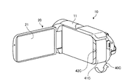
図10を用いて、SDカードカバー40Cについて説明する。SDカードカバー40Cは、例えば、接続端子と、SDカードを含む記憶メディア用のスロットとに対して開閉自在に配置されたカバーである。SDカードカバー40Cは、筐体11に対して開閉操作される。SDカードカバー40Cは、操作検出部41Cと発光部42Cとを有する。
操作検出部41Cは、SDカードカバー40Cに対する開閉操作を検出する。より詳しくは、操作検出部41Cは、SDカードカバー40Cが開閉操作を検出すると、操作情報を図1の制御部70に出力する。
発光部42Cは、SDカードカバー40Cの位置を知らせるために発光する発光素子である。発光部42Cは、SDカードカバー40Cの近傍に配置されている。発光部42Cは、SDカードカバー40Cの開閉状態に合わせて点灯/消灯を切り替える。発光部42Cは、SDカードカバー40Cの操作を含む取扱説明データがモニタ20に表示されるとき、点灯/消灯を切り替える。本実施形態では、発光部42Cは、SDカードカバー40Cの操作を含む取扱説明動画100が再生されるとき、点灯/消灯を切り替える。
図12を用いて、SDカードスロット40Dについて説明する。SDカードスロット40Dは、SDカードを着脱可能なスロットである。SDカードスロット40Dには、SDカードが抜き差しされる。SDカードスロット40Dは、操作検出部41Dと発光部42Dとを有する。
操作検出部41Dは、SDカードスロット40Dに対するSDカードの抜き差し操作を検出する。より詳しくは、操作検出部41Dは、SDカードスロット40Dに対するSDカードの抜き差し操作を検出すると、操作情報を図1の制御部70に出力する。
発光部42Dは、SDカードスロット40Dの位置を知らせるために発光する発光素子である。発光部42Dは、SDカードスロット40Dの近傍に配置されている。発光部42Dは、SDカードスロット40DへのSDカードの抜き差し状態に合わせて点灯/消灯を切り替える。発光部42Dは、SDカードスロット40Dの操作を含む取扱説明データがモニタ20に表示されるとき、点灯/消灯を切り替える。本実施形態では、発光部42Dは、SDカードスロット40Dの操作を含む取扱説明動画100が再生されるとき、点灯/消灯を切り替える。
ここで図1に戻り、動作部50、記憶部60について説明する。動作部50は、操作部40に対して行われた操作に基づいて動作する。例えば、動作部50は、START/STOPボタン40Aまたは撮影開始/停止ボタン40Bに対する操作によって動作する撮像部である。例えば、動作部50は、SDカードスロット40Dに対するSDカードの抜き差し操作によって動作する読取部である。例えば、動作部50は、モニタ20の本体の開閉操作によって動作する電源部である。
記憶部60は、電子機器10におけるデータの一時記憶などに用いられる。記憶部60は、例えば、RAM(Random Access Memory)、ROM(Read Only Memory)、フラッシュメモリ(Flash Memory)などの半導体メモリ素子、または、ハードディスク、光ディスクなどの記憶装置である。または、図示しない通信装置を介して無線接続される外部記憶装置であってもよい。記憶部60は、取扱説明データと、取扱説明データの再生位置に関連付けられ、記取扱説明データにおいて説明している操作対象であるモニタ20の本体および操作部40の制御情報を示す操作部制御情報とを記憶している。
取扱説明データは、ユーザが電子機器10を操作する際の操作方法を説明する。取扱説明データは、操作ごとに、ユーザが操作を行うべき操作対象と、操作対象をどのように操作するかを説明した操作方法とを含む。取扱説明データは、メタデータの一つとして操作対象に関する操作部制御情報を参照するための識別情報とを有する。取扱説明データは、例えば、印刷された取扱説明書を動画像によって表した動画と、印刷された取扱説明書を公開するWEBページのデータを含む画像と、印刷された取扱説明書を電子的に保存した電子ファイルとを含む。本実施形態では、取扱説明データは、取扱説明動画100として説明する。
取扱説明動画100は、電子機器10の取り扱いを説明する一つ以上の動画である。より詳しくは、取扱説明動画100は、操作ごとに、ユーザが操作を行うべき操作対象であるモニタ20の本体および操作部40と、操作対象をどのように操作するかを説明する操作方法とを含む。例えば、電子機器10の「電源を入れる」操作についての取扱説明動画100は、操作部40である電源ボタンを押下操作することを説明する。取扱説明動画100には、操作部制御情報が関連付けられている。より詳しくは、取扱説明動画100には、ユーザによる操作部40の操作が求められる再生位置に、操作部制御情報を識別する識別情報が関連付けられている。一つの取扱説明動画100に対して、複数の操作部制御情報が関連付けられていてもよい。
取扱説明動画100の再生位置は、例えば、取扱説明動画100の区切りを示すチャプター情報、取扱説明動画100の所定位置を示すスタンプ情報、または、取扱説明動画100の再生開始からの再生時間を示す時間情報である。
図3を用いて、取扱説明動画100の一例について説明する。図3は、第一実施形態に係る電子機器の取扱説明動画の一例を説明する図である。例えば、取扱説明動画100は、複数の動画を含む。取扱説明動画100の一つである動画i1は、メタデータに操作部制御情報の識別情報「A」を含む。取扱説明動画100の一つである動画i3は、メタデータに操作部制御情報の識別情報「B」を含む。取扱説明動画100の一つである動画i2、動画i4は、メタデータに操作部制御情報の識別情報を含まない。
操作部制御情報は、取扱説明動画100において説明している操作対象の制御情報である。操作部制御情報は、操作部制御情報を識別する識別情報ごとに、操作対象と、動作情報とを記憶する。より詳しくは、操作部制御情報は、操作対象と、操作対象に対する操作によって動作する動作部50の動作情報とを記憶する。操作部制御情報は、取扱説明動画100の再生位置が所定位置となると、操作対象の発光部を発光させる制御信号を出力するための制御情報を含む。また、操作部制御情報は、操作対象に対する操作が行われると、操作によって動作する動作部50に対して制御信号を出力するための制御情報を含む。
図4を用いて、操作部制御情報の一例について説明する。図4は、第一実施形態に係る電子機器の操作部制御情報の一例を説明する図である。例えば、識別情報Aの操作部制御情報は、操作対象の操作部40がSTART/STOPボタン40Aまたは撮影開始/停止ボタン40Bであり、動作情報が「停止状態のとき撮影開始」、「撮影状態のとき停止」である。識別情報Bの操作部制御情報は、操作対象の操作部40がSDカードカバー40Cであり、動作情報が「電源を切る」である。
ここで図1に戻り、制御部70、再生制御部71、表示制御部72、発光制御部73、操作情報取得部74、動作制御部75について説明する。
制御部70は、モニタ20とスピーカ30と操作部40と動作部50と記憶部60との制御を実行する。より詳しくは、制御部70は、取扱説明動画100の再生制御を行う。そして、制御部70は、再生している取扱説明動画100において説明されているモニタ20の本体の発光部22または各操作部40の発光部42の発光を制御する。そして、制御部70は、モニタ20の本体または各操作部40に対する操作に応じて、動作部50の動作を制御する。制御部70は、例えば、CPU(Central Processing Unit)や映像処理用プロセッサなどで構成された演算処理装置(制御部)である。制御部70は、記憶部60に記憶されているプログラムをメモリにロードして、プログラムに含まれる命令を実行する。制御部70は、一または複数の装置で構成されていてもよい。制御部70は、再生制御部71と、表示制御部72と、発光制御部73と、操作情報取得部74と、動作制御部75とを有する。
再生制御部71は、取扱説明動画100の再生を制御する。より詳しくは、再生制御部71は、モニタ20における取扱説明動画100の表示と、スピーカ30における取扱説明動画100の音声の出力とを実行する制御信号を出力する。再生制御部71は、ユーザの操作に基づいて選択された取扱説明動画100を記憶部60から取得し、モニタ20に動画を表示し、スピーカ30によって音声を出力する。
また、再生制御部71は、取扱説明動画100が再生されていない状態において、操作部40をユーザが操作すると、操作された操作部40に関連する取扱説明動画100をモニタ20に表示してもよい。再生制御部71は、操作部40に関連する取扱説明動画100が複数ある場合は、各動画のサムネイルをモニタ20にリストとして表示してもよい。
表示制御部72は、再生制御部71による制御に基づいて、モニタ20に取扱説明動画100を表示する映像信号を出力したり、出力を停止したりする。表示制御部72は、常時、取扱説明動画100の再生中の位置を示す再生位置を取得可能である。表示制御部72は、常時、モニタ20において再生している取扱説明動画100の再生位置を取得可能である。表示制御部72は、取得した取扱説明動画100の再生位置を発光制御部73に出力する。
表示制御部72は、操作対象が画面20aに表示されタッチパネルによって操作する画像である場合、操作対象の画像を点灯するとき、画面20aにおける取扱説明動画100の表示態様を変えて、操作対象の画像を前面に表示する。より詳しくは、表示制御部72は、操作対象の画像を点灯するとき、取扱説明動画100の画面20aにおける表示範囲を縮小して、操作対象の画像を画面20aの前面に表示してもよい。表示制御部72は、操作対象の画像を点灯するとき、取扱説明動画100を半透過にして、操作対象の画像を画面20aの前面に表示してもよい。表示制御部72は、操作対象の画像を点灯するとき、取扱説明動画100の画面20aにおける表示位置をずらして、操作対象の画像を画面20aの前面に表示してもよい。
発光制御部73は、モニタ20に表示している取扱説明動画100において説明している操作対象であるモニタ20の本体または操作部40の近傍に配置された発光部を発光させる。発光制御部73は、モニタ20の本体の発光部22または操作部40の発光部42の点灯/消灯を制御する制御信号を出力する。より詳しくは、発光制御部73は、取扱説明動画100の再生時に、表示制御部72によって取得した再生位置と、再生位置に関連付けられた操作部制御情報とに基づいて、モニタ20に表示している取扱説明動画100において説明されているモニタ20の本体の発光部22または操作部40の発光部42を点灯する。発光制御部73は、モニタ20の本体の発光部22または操作部40の発光部42を点灯した後、操作情報取得部74によって操作対象であるモニタ20の本体または操作部40に対するユーザの操作が検出されると、モニタ20の本体の発光部22または操作部40の発光部42を消灯する。
発光制御部73は、操作部40が画面20aに表示された画像である場合、色または輝度を変化させた操作部40の画像を表示させる。発光制御部73は、色または輝度を変化させた操作部40の画像を表示した後、操作情報取得部74によって操作部40の画像に対するユーザの操作が検出されると、点灯していない通常状態の操作部40の画像を表示する。
操作情報取得部74は、モニタ20の本体の操作検出部21または操作部40の操作検出部41で検出した操作情報を取得する。より詳しくは、操作情報取得部74は、モニタ20の本体または操作部40に対するユーザの操作に係る操作情報を取得する。操作情報取得部74は、取得した操作情報を動作制御部75に出力する。
動作制御部75は、操作情報取得部74で取得した操作情報に基づいて、モニタ20の本体または操作部40に対するユーザの操作が検出されると、対象の動作部50の動作を制御する制御信号を出力する。
次に、図5を用いて、電子機器10が行う処理の方法及び作用について説明する。図5は、第一実施形態に係る電子機器が行う処理の一例を示すフローチャートである。
ユーザが取扱説明動画100の再生開始操作を行う。より詳しくは、例えば、ユーザが、メニュー画面に表示された項目の中から内容を確認したい項目を選択する。メニュー画面には、ビデオカメラである電子機器10の操作の項目を表示する。例えば、項目としては、「電源を入れる」、「動画を撮る」、「SDカードを入れる」のような各操作である。
ユーザが取扱説明動画100の中から、確認したい項目を選択して再生開始操作を行うと、電子機器10は、選択された項目に対応した取扱説明動画100を再生する(ステップS11)。より詳しくは、電子機器10は、再生制御部71によって、選択された項目に対応した取扱説明動画100を再生する制御信号を出力する。電子機器10は、表示制御部72によって、モニタ20に取扱説明動画100を表示する映像信号を出力する。電子機器10は、ステップS12に進む。
電子機器10は、取扱説明動画100の再生位置が、操作対象を点灯させる位置に到達したか否かを判定する(ステップS12)。より詳しくは、電子機器10は、再生制御部71によって、取扱説明動画100の再生位置を検出し、取扱説明動画100の再生位置がモニタ20の本体または操作部40を点灯させる位置に到達したか否か、言い換えると、操作部制御情報が関連付けられた位置に到達したか否かを判定する。電子機器10は、操作部制御情報が関連付けられた位置に到達したと判定される場合、取扱説明動画100の再生位置がモニタ20の本体または操作部40を点灯させる位置に到達したと判定して(ステップS12でYes)、ステップS13に進む。電子機器10は、操作部制御情報が関連付けられた位置に到達していないと判定される場合、取扱説明動画100の再生位置がモニタ20の本体または操作部40を点灯させる位置に到達していないと判定し(ステップS12でNo)、ステップS12の処理を再度実行する。
電子機器10は、操作対象を点灯させる(ステップS13)。より詳しくは、電子機器10は、発光制御部73によって、操作部制御情報に基づいて、モニタ20の本体の発光部22または操作部40の発光部42を点灯する。電子機器10は、ステップS14に進む。
電子機器10は、操作対象への入力があるか否かを判定する(ステップS14)。より詳しくは、電子機器10は、操作情報取得部74によって、モニタ20の本体または操作部40への入力の有無を検出する。電子機器10は、操作情報取得部74によって、モニタ20の本体または操作部40への入力が検出された場合(ステップS14でYes)、ステップS15に進む。電子機器10は、操作情報取得部74によって、モニタ20の本体または操作部40への入力が検出されない場合(ステップS14でNo)、ステップS14の処理を繰り返す。
電子機器10は、動作を実行する(ステップS15)。より詳しくは、電子機器10は、動作制御部75によって、モニタ20の本体または操作部40への入力に応じて動作部50の動作を実行する。電子機器10は、ステップS16に進む。
電子機器10は、取扱説明動画100の再生を終了する(ステップS16)。より詳しくは、電子機器10は、再生制御部71によって、取扱説明動画100の再生を終了する。電子機器10は、処理を終了する。
また、電子機器10は、一つの取扱説明動画100に複数の操作部制御情報が関連付けられている場合、ステップS11からステップS15の処理を、取扱説明動画100の再生が終了するまで操作部制御情報の数だけ繰り返す。
図6ないし図8を用いて、例えば、動画を撮る操作について説明する取扱説明動画100を再生するとき、電子機器10が行う処理について説明する。図6は、第一実施形態に係る電子機器の取扱説明動画の一例を示す図である。図7は、第一実施形態に係る電子機器の操作部の一例を示す斜視図である。図8は、第一実施形態に係る電子機器の取扱説明動画が表示された表示面の一例を示す図である。
図6に示すように、電子機器10は、再生制御部71によって、動画を撮る操作について説明する取扱説明動画100をモニタ20に表示し、スピーカ30で取扱説明動画100の音声を出力する。
取扱説明動画100の再生位置が、図6に示す動画像をモニタ20に表示する位置であるとき、関連付けられた操作部制御情報が存在する。
図7、図8に示すように、電子機器10は、モニタ20に図6に示す動画像が表示されると、操作部制御情報に基づいて、発光制御部73によって、操作部40であるSTART/STOPボタン40Aの発光部42A、および、撮影開始/停止ボタン40Bの発光部42Bを点灯する。
本実施形態では、撮影開始/停止ボタン40Bの発光部42Bが点灯されるとき、表示制御部72によって、画面20aにおける取扱説明動画100の表示範囲が縮小されて、撮影開始/停止ボタン40Bおよび発光部42Bが画面20aの前面に表示されるようにする。
ユーザは、発光部42Aおよび発光部42Bが点灯していることにより、START/STOPボタン40Aまたは画面20aに表示された撮影開始/停止ボタン40Bを操作すればよいことを確認する。ユーザは、START/STOPボタン40Aを押下操作するか、または、撮影開始/停止ボタン40Bをタッチ操作する。
電子機器10は、START/STOPボタン40A、または、画面20aに表示された撮影開始/停止ボタン40Bに対して操作が入力されたことを、操作検出部41Aまたは操作検出部41Bによって検出する。電子機器10は、操作情報取得部74によって操作情報を取得する。電子機器10は、動作制御部75によって撮像部に対して撮影を開始する制御信号を出力する。
図9ないし図12を用いて、例えば、SDカードを入れる操作について説明する取扱説明動画100を再生するとき、電子機器10が行う処理について説明する。図9は、第一実施形態に係る電子機器の取扱説明動画の他の例を示す図である。図10は、第一実施形態に係る電子機器の操作部の他の例を示す斜視図である。図11は、第一実施形態に係る電子機器の操作部の他の例を示す斜視図である。図12は、第一実施形態に係る電子機器の操作部の他の例を示す斜視図である。
図9に示すように、電子機器10は、再生制御部71によって、SDカードを入れる操作について説明する取扱説明動画100をモニタ20に表示し、スピーカ30で取扱説明動画100の音声を出力する。
取扱説明動画100には、3つの操作部制御情報が関連付けられている。より詳しくは、取扱説明動画100の再生位置が、図9に示す動画像がモニタ20に表示された状態で、「1 SDカードカバーを開ける」という音声が再生される位置であるとき、「2 液晶モニタを閉じて本機の電源を切る」という音声が再生される位置であるとき、および、「3 SDカードを入れる」という音声が再生される位置であるとき、関連付けられた操作部制御情報がそれぞれ存在する。
図10に示すように、電子機器10は、図9に示す動画像がモニタ20に表示された状態で、「1 SDカードカバーを開ける」という音声が再生されると、操作部制御情報に基づいて、発光制御部73によって、操作部40であるSDカードカバー40Cの発光部42Cを点灯する。
ユーザは、SDカードカバー40Cの発光部42Cが点灯していることにより、SDカードカバー40Cを操作すればよいことを確認する。ユーザは、SDカードカバー40Cを開操作する。
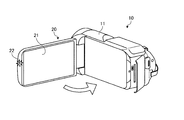
図11に示すように、電子機器10は、図9に示す動画像がモニタ20に表示された状態で、「2 液晶モニタを閉じて本機の電源を切る」という音声が再生されると、操作部制御情報に基づいて、発光制御部73によって、操作部40であるモニタ20の本体の発光部22を点灯する。
ユーザは、モニタ20の本体の発光部22が点灯していることにより、モニタ20の本体を操作すればよいことを確認する。ユーザは、モニタ20の本体を閉操作する。
電子機器10は、モニタ20が閉操作されたことを操作検出部21によって検出する。電子機器10は、操作情報取得部74によって操作情報を取得する。電子機器10は、動作制御部75によって電子機器10の電源をオフにする制御信号を出力する。
図12に示すように、電子機器10は、図9に示す動画像がモニタ20に表示された状態で、「3 SDカードを入れる」という音声が再生されると、操作部制御情報に基づいて、発光制御部73によって、操作部40であるSDカードスロット40Dの発光部42Dを点灯する。
ユーザは、SDカードスロット40Dの発光部42Dが点灯していることにより、SDカードスロット40Dに対して操作すればよいことを確認する。ユーザは、SDカードスロット40DにSDカードを挿入する。
電子機器10は、SDカードスロット40DにSDカードが挿入されたことを操作検出部41Dによって検出する。電子機器10は、操作情報取得部74によって操作情報を取得する。電子機器10は、動作制御部75によって読取部にSDカードを読み取る制御信号を出力する。
このように、電子機器10は、再生している取扱説明動画100において説明されているモニタ20の本体の発光部22または各操作部40の発光部42の発光を制御する。電子機器10は、モニタ20の本体または各操作部40に対する操作に応じて、動作部50の動作を制御する。
つづいて、モニタ20において取扱説明動画100が再生されていない状態において、操作部40を操作した場合について説明する。なお、通常の操作と異なる動作をするように、予め「説明モード」に設定したり、操作部40に対する操作を通常の操作とは異なる長押しなどに変えたりするものとする。
ユーザは、モニタ20において取扱説明動画100が再生されていない状態において、操作部40を操作する。
再生制御部71は、取扱説明動画100が再生されていない状態において、操作部40をユーザが操作するので、操作された操作部40に関連する取扱説明動画100をモニタ20に表示する。再生制御部71は、操作部40に関連する取扱説明動画100が複数ある場合は、各動画のサムネイルをモニタ20にリストにして表示してもよい。
このように、電子機器10は、モニタ20において取扱説明動画100が再生されていない状態において、操作部40を操作すると、操作された操作部40に関連する取扱説明動画100をモニタ20に表示する。
上述したように、本実施形態は、取扱説明動画100と、取扱説明動画100に対応して操作を行う操作対象とを関連付けて記憶する。本実施形態は、取扱説明動画100が再生され、再生位置が所定位置になると、取扱説明動画100において説明されているモニタ20の本体の発光部22または操作部40の発光部42を点灯する。本実施形態によれば、取扱説明動画100の再生位置に応じて、操作を行うモニタ20の本体の発光部22または操作部40の発光部42が点灯する。これにより、本実施形態は、ユーザが取扱説明動画100によって操作を確認する際に、操作対象を迷ったり誤って操作したりすることを抑制することができる。
これに対して、従来の印刷された取扱説明書を参照して、操作を確認する場合、取扱説明書の該当ページを参照しながら、電子機器10に照らし合わせて操作対象の位置を確認したり、操作を確認する必要があった。このため、初めて電子機器10を操作する場合や、電子機器10の操作に不慣れなユーザが使用する場合には、操作の確認に手間と時間とを要するおそれがある。
また、本実施形態は、取扱説明動画100が再生されていない状態において、操作部40をユーザが操作すると、操作された操作部40に関連する取扱説明動画100をモニタ20に表示する。これにより、ユーザが、電子機器10の操作部40の操作がわからないときに、取扱説明動画100によって、操作部40で行うことができる操作を容易に確認することができる。従来の印刷された取扱説明書において当該操作部40に関連した操作を探すことに比べて、操作の確認を容易にすることができる。
このように、本実施形態は、電子機器10の操作をよりわかり易く説明することができる。本実施形態は、電子機器10の操作をより適切に支援することができる。このようにして、本実施形態によれば、操作性をよくすることができる。
[第二実施形態]
図13を参照しながら、本実施形態に係る電子機器10について説明する。図13は、第二実施形態に係る電子機器が行う処理の一例を示すフローチャートである。電子機器10は、基本的な構成は第一実施形態の電子機器10と同様である。以下の説明においては、電子機器10と同様の構成要素には、同一の符号または対応する符号を付し、その詳細な説明は省略する。本実施形態の電子機器10は、制御部70における処理が、第一実施形態と異なる。
図13を参照しながら、本実施形態に係る電子機器10について説明する。図13は、第二実施形態に係る電子機器が行う処理の一例を示すフローチャートである。電子機器10は、基本的な構成は第一実施形態の電子機器10と同様である。以下の説明においては、電子機器10と同様の構成要素には、同一の符号または対応する符号を付し、その詳細な説明は省略する。本実施形態の電子機器10は、制御部70における処理が、第一実施形態と異なる。
再生制御部71は、再生している取扱説明動画100と異なる取扱説明動画100へ移動する操作であるジャンプ操作がされると、移動先であるジャンプ先の取扱説明動画100を再生する。より詳しくは、再生制御部71は、取扱説明動画100がジャンプされたことを検出すると、ジャンプ先の取扱説明動画100を再生する制御信号を出力する。ジャンプ操作されたとは、例えば、早送り操作またはジャンプ操作のことをいう。
表示制御部72は、取扱説明動画100の再生中に、ユーザの操作によって取扱説明動画100がジャンプされたことを検出する。表示制御部72は、取扱説明動画100の再生中に、再生制御部71による制御に基づいて、モニタ20にジャンプ先の取扱説明動画100を表示する映像信号を出力する。
図13に示すフローチャートのステップS21、ステップS23ないしステップS27の処理は、図5に示すフローチャートのステップS11、ステップS12ないしステップS16の処理と同様の処理を行う。
電子機器10は、取扱説明動画100の再生中に、ジャンプ操作がされたか否かを判定する(ステップS22)。より詳しくは、電子機器10は、再生制御部71によって、ジャンプ操作が検出された場合(ステップS22でYes)、ステップS28に進む。電子機器10は、再生制御部71によって、ジャンプ操作が検出されない場合(ステップS22でNo)、ステップS23に進む。
ユーザが取扱説明動画100の再生中にジャンプ操作を行うと(ステップS22でYes)、電子機器10は、ジャンプ先の取扱説明動画100を再生する(ステップS28)。より詳しくは、電子機器10は、再生制御部71によって、ジャンプ先の取扱説明動画100を再生する制御信号を出力する。電子機器10は、表示制御部72によって、モニタ20にジャンプ先の取扱説明動画100を表示する映像信号を出力する。電子機器10は、ステップS29に進む。
電子機器10は、ジャンプ先の取扱説明動画100の再生位置が、操作対象を点灯させる位置に到達したか否かをを判定する(ステップS29)。電子機器10は、操作部制御情報が関連付けられた位置に到達したと判定される場合、ジャンプ先の取扱説明動画100の再生位置がモニタ20の本体または操作部40を点灯させる位置に到達したと判定して(ステップS29でYes)、ステップS30に進む。電子機器10は、操作部制御情報が関連付けられた位置に到達していないと判定される場合、ジャンプ先の取扱説明動画100の再生位置がモニタ20の本体または操作部40を点灯させる位置に到達していないと判定し(ステップS29でNo)、ステップS29の処理を再度実行する。
電子機器10は、ジャンプ先の操作対象を点灯させる(ステップS30)。より詳しくは、電子機器10は、発光制御部73によって、操作部制御情報に基づいて、モニタ20の本体の発光部22または操作部40の発光部42を点灯する。電子機器10は、ステップS31に進む。
電子機器10は、ジャンプ先の操作対象への入力があるか否かを判定する(ステップS31)。電子機器10は、操作情報取得部74によって、モニタ20の本体または操作部40への入力が検出された場合(ステップS31でYes)、ステップS32に進む。電子機器10は、操作情報取得部74によって、モニタ20の本体または操作部40への入力が検出されない場合(ステップS31でNo)、ステップS31の処理を繰り返す。
電子機器10は、ジャンプ先の動作を実行する(ステップS32)。より詳しくは、電子機器10は、動作制御部75によって、モニタ20の本体または操作部40への入力に応じて動作部50の動作を実行する。電子機器10は、ステップS33に進む。
電子機器10は、ジャンプ先の取扱説明動画100の再生を終了する(ステップS33)。より詳しくは、電子機器10は、再生制御部71によって、取扱説明動画100の再生を終了する。電子機器10は、処理を終了する。
上述したように、本実施形態は、取扱説明動画100の再生中にジャンプ操作がされたとき、ジャンプ先の取扱説明動画100が再生され、再生位置が所定位置になると、ジャンプ先の取扱説明動画100において説明されているモニタ20の本体の発光部22または操作部40の発光部42を点灯する。本実施形態によれば、ジャンプ先の取扱説明動画100の再生位置に応じて、操作を行うモニタ20の本体の発光部22または操作部40の発光部42が点灯する。これにより、本実施形態は、ユーザが取扱説明動画100によって操作を確認する際に、ジャンプ操作を行ったとしても、適切に操作を確認することができる。
[第三実施形態]
図14を参照しながら、本実施形態に係る電子機器10について説明する。図14は、第三実施形態に係る電子機器の構成例を示すブロック図である。本実施形態では、取扱説明動画100を再生する表示装置200と、電子機器300とが独立した機器で構成されている。
図14を参照しながら、本実施形態に係る電子機器10について説明する。図14は、第三実施形態に係る電子機器の構成例を示すブロック図である。本実施形態では、取扱説明動画100を再生する表示装置200と、電子機器300とが独立した機器で構成されている。
表示装置200は、主に、第一実施形態のモニタ20の機能を有するモニタ210、スピーカ30の機能を有するスピーカ220、記憶部60の機能を有する記憶部230、および、これらに対する各種制御を行う制御部240を有する。制御部240は、再生制御部241と表示制御部242と制御信号出力部243とを有する。再生制御部241は、再生制御部71と同様の機能を有する。表示制御部242は、表示制御部72と同様の機能を有する。制御信号出力部243は、発光制御部73と同様の機能を有する。より詳しくは、制御信号出力部243は、取扱説明動画100の再生時に、操作部制御情報に基づいて、取扱説明動画100において説明されているモニタ20の本体の発光部22または操作部40の発光部42を点灯する制御信号を電子機器300に出力する。
電子機器300は、操作部40と同様に構成された操作部310と、動作部50と同様に構成された動作部320と、これらに対する各種制御を行う制御部330とを有する。制御部330は、制御信号取得部331と発光制御部332と操作情報取得部333と動作制御部334とを有する。制御信号取得部331は、表示装置200から制御信号を取得する。発光制御部332は、発光制御部73に対応する機能を有する。操作情報取得部333は、操作情報取得部74に対応する機能を有する。動作制御部334は、動作制御部75に対応する機能を有する。
上述したように、本実施形態によれば、情報を表示するモニタを有していない電子機器300であっても、例えば、携帯通信端末またはコンピュータを含むモニタを有する表示装置200を使用して、適切に操作を支援することができる。
これまで本発明に係る電子機器10について説明したが、上述した実施形態以外にも種々の異なる形態にて実施されてよいものである。
図示した電子機器10の各構成要素は、機能概念的なものであり、必ずしも物理的に図示の如く構成されていなくてもよい。すなわち、各装置の具体的形態は、図示のものに限られず、各装置の処理負担や使用状況などに応じて、その全部または一部を任意の単位で機能的または物理的に分散または統合してもよい。
電子機器10の構成は、例えば、ソフトウェアとして、メモリにロードされたプログラムなどによって実現される。上記実施形態では、これらのハードウェアまたはソフトウェアの連携によって実現される機能ブロックとして説明した。すなわち、これらの機能ブロックについては、ハードウェアのみ、ソフトウェアのみ、または、それらの組み合わせによって種々の形で実現できる。
電子機器10は、取扱説明動画100において説明されているモニタ20の本体の発光部22または操作部40の発光部42を点灯するとともに、例えば、操作部40または操作部40を移動する移動機構などを駆動する図示しない操作制御部を制御部70に有してもよい。より詳しくは、例えば、図9に示す、SDカードを入れる操作について説明する取扱説明動画100が再生されると、発光制御部73によって、SDカードカバー40Cの発光部42Cを点灯するとともに、操作制御部によって、SDカードカバー40Cの移動機構を駆動してSDカードカバー40Cを開操作する。これにより、例えば、操作部40の操作が難しいと予想される場合、注意を要する場合などに、操作制御部によって操作部40の操作を実行することができる。このようにすることで、より適切に操作を支援することができる。
上記の実施形態では、取扱説明データは、取扱説明動画100として説明したが、これに限定されない。取扱説明データが取扱説明書をホームページなどで画像として公開するWEBページまたは電子ファイルであってもよい。この場合、発光制御部73によって、操作対象の操作部40の発光部42を発光するとき、表示制御部72によって、取扱説明データの該当ページにおいて操作対象の操作部40を示す文字列の色を変えてもよい。また、一ページに複数の操作対象の操作部40が表示されている場合、操作の順番に従って、操作対象の操作部40を示す文字列の色を変え、操作が完了したら、次の操作対象の操作部40を示す文字列の色を変えるようにすることが好ましい。
例えば、年齢、性別、電子機器10の使用頻度、同じ取扱説明動画100の再生回数など電子機器10のユーザ属性によって、モニタ20に表示する取扱説明動画100における説明を詳細化または簡略化したり、文字の大きさを変えたりしてもよい。さらに、ユーザ属性によって、上述したように、モニタ20の本体の発光部22または操作部40の発光部42を点灯するとともに、操作制御部によって操作部40の操作を実行するようにしてもよい。これにより、ユーザの属性に合わせて、より適切に操作を支援することができる。
上記の実施形態では、取扱説明動画100が再生され、再生位置が所定位置になると、取扱説明動画100において説明されているモニタ20の本体の発光部22または操作部40の発光部42を点灯するとしたが、他の方法であってもよい。再生位置が所定位置になると、例えば、操作部40が振動するようにしてもよい。この場合、操作部40は、発光部42に代えて、振動部(図示せず)を有してもよい。振動部は、例えば、振動モータや振動板である。
さらに、他の方法としては、再生位置が所定位置になると、例えば、スピーカ30が音声を発してもよい。例えば、操作部40の位置が把握できるように「右横のボタンを押して下さい」など、操作部40の位置を含めた音声を発してもよい。
上記に記載した構成要素には、当業者が容易に想定できるもの、実質的に同一のものを含む。さらに、上記に記載した構成は適宜組み合わせが可能である。また、本発明の要旨を逸脱しない範囲において構成の種々の省略、置換または変更が可能である。
10 電子機器
20 モニタ
21 操作検出部
22 発光部
30 スピーカ
40 操作部
41 操作検出部
42 発光部
50 動作部
60 記憶部
70 制御部
71 再生制御部
72 表示制御部
73 発光制御部
74 操作情報取得部
75 動作制御部
100 取扱説明動画
20 モニタ
21 操作検出部
22 発光部
30 スピーカ
40 操作部
41 操作検出部
42 発光部
50 動作部
60 記憶部
70 制御部
71 再生制御部
72 表示制御部
73 発光制御部
74 操作情報取得部
75 動作制御部
100 取扱説明動画
Claims (5)
- 操作を受付可能な操作部と、
前記操作部に対応して配置され、前記操作部の位置を知らせる発光部と、
表示部に表示している電子機器の取り扱いを説明する取扱説明データにおいて説明している前記操作部に対応して配置された前記発光部を発光させる発光制御部と、
を備えることを特徴とする電子機器。 - 前記取扱説明データを再生することを制御する再生制御部と、
前記再生制御部による制御に基づいて、前記取扱説明データを前記表示部に表示する映像信号を出力し、前記取扱説明データの再生中の位置を示す再生位置を取得可能な表示制御部と、
を備え、
前記発光制御部は、前記表示制御部によって取得した前記再生位置に基づいて、前記表示部に表示している前記取扱説明データにおいて説明している前記操作部に対応して配置された前記発光部を発光させる、
請求項1に記載の電子機器。 - 前記再生制御部は、前記取扱説明データを再生していない状態において、前記操作部に対して操作されると、操作された前記操作部の取り扱いを説明する前記取扱説明データを再生する、
請求項2に記載の電子機器。 - 操作を受付可能な操作部と、
前記操作部に対応して配置され、前記操作部の位置を知らせる発光部と、
を有する電子機器の操作支援方法であって、
表示部に表示している電子機器の取り扱いを説明する取扱説明データにおいて説明している前記操作部に対応して配置された前記発光部を発光させる発光制御ステップ、
を含むことを特徴とする電子機器の操作支援方法。 - 操作を受付可能な操作部と、
前記操作部に対応して配置され、前記操作部の位置を知らせる発光部と、
を有する電子機器として動作するコンピュータに実行させるためのプログラムであって、
表示部に表示している電子機器の取り扱いを説明する取扱説明データにおいて説明している前記操作部に対応して配置された前記発光部を発光させる発光制御ステップ、
を電子機器として動作するコンピュータに実行させるためのプログラム。
Applications Claiming Priority (2)
| Application Number | Priority Date | Filing Date | Title |
|---|---|---|---|
| JP2017184413A JP2019061401A (ja) | 2017-09-26 | 2017-09-26 | 電子機器、操作支援方法及びプログラム |
| JP2017-184413 | 2017-09-26 |
Publications (1)
| Publication Number | Publication Date |
|---|---|
| WO2019064808A1 true WO2019064808A1 (ja) | 2019-04-04 |
Family
ID=65903433
Family Applications (1)
| Application Number | Title | Priority Date | Filing Date |
|---|---|---|---|
| PCT/JP2018/025870 Ceased WO2019064808A1 (ja) | 2017-09-26 | 2018-07-09 | 電子機器、操作支援方法及びプログラム |
Country Status (2)
| Country | Link |
|---|---|
| JP (1) | JP2019061401A (ja) |
| WO (1) | WO2019064808A1 (ja) |
Citations (3)
| Publication number | Priority date | Publication date | Assignee | Title |
|---|---|---|---|---|
| JP2001092576A (ja) * | 1999-09-22 | 2001-04-06 | Furuno Electric Co Ltd | 表示装置および測深装置 |
| JP2010050596A (ja) * | 2008-08-20 | 2010-03-04 | Sharp Corp | デジタル放送受信装置 |
| JP2010268207A (ja) * | 2009-05-14 | 2010-11-25 | Toshiba Corp | 携帯端末 |
-
2017
- 2017-09-26 JP JP2017184413A patent/JP2019061401A/ja active Pending
-
2018
- 2018-07-09 WO PCT/JP2018/025870 patent/WO2019064808A1/ja not_active Ceased
Patent Citations (3)
| Publication number | Priority date | Publication date | Assignee | Title |
|---|---|---|---|---|
| JP2001092576A (ja) * | 1999-09-22 | 2001-04-06 | Furuno Electric Co Ltd | 表示装置および測深装置 |
| JP2010050596A (ja) * | 2008-08-20 | 2010-03-04 | Sharp Corp | デジタル放送受信装置 |
| JP2010268207A (ja) * | 2009-05-14 | 2010-11-25 | Toshiba Corp | 携帯端末 |
Also Published As
| Publication number | Publication date |
|---|---|
| JP2019061401A (ja) | 2019-04-18 |
Similar Documents
| Publication | Publication Date | Title |
|---|---|---|
| JP5347673B2 (ja) | 情報処理装置、情報処理方法及びプログラム | |
| JP4179269B2 (ja) | 携帯型電子機器、表示方法、そのプログラム及び表示操作装置 | |
| TW523632B (en) | Digital camera and method of obtaining information relating to at least one function associated with a digital camera | |
| JP2021073567A (ja) | 音声制御方法、端末機器、クラウドサーバ及びシステム | |
| US8536437B2 (en) | Musical score playing device and musical score playing program | |
| KR101179601B1 (ko) | 편리한 이동 모드를 위한 디지털 영상 처리 장치의 제어방법, 및 이 방법을 채용한 디지털 영상 처리 장치 | |
| JP2007181068A (ja) | リモコン装置 | |
| JP6128919B2 (ja) | 表示制御装置及びその制御方法 | |
| JP2008033844A (ja) | 表示装置、制御方法およびプログラム | |
| JP6069927B2 (ja) | コンテンツ表示装置、コンテンツ表示方法およびプログラム | |
| KR101776674B1 (ko) | 휴대용 영상 편집 장치 및 그 동작 방법 | |
| JP2009164757A (ja) | 画像表示装置及び撮像装置 | |
| WO2019064808A1 (ja) | 電子機器、操作支援方法及びプログラム | |
| US10976895B2 (en) | Electronic apparatus and controlling method thereof | |
| CN100432912C (zh) | 便携式电子设备及其显示方法和图形用户接口装置 | |
| CN106453987A (zh) | 管理文件的装置以及其方法 | |
| JP4881360B2 (ja) | 情報処理装置、入力支援方法および入力支援プログラム | |
| JP2010282245A (ja) | 電子機器 | |
| JP2006330283A (ja) | 電子機器 | |
| JP2010259028A (ja) | 画像表示装置 | |
| JP5661511B2 (ja) | 携帯端末装置 | |
| JP2011248733A (ja) | 電子機器 | |
| WO2011010442A1 (ja) | 情報処理端末 | |
| JP2011118838A (ja) | 電子機器 | |
| KR20190111310A (ko) | 전자 장치 및 전자 장치의 기능 실행 방법 |
Legal Events
| Date | Code | Title | Description |
|---|---|---|---|
| 121 | Ep: the epo has been informed by wipo that ep was designated in this application |
Ref document number: 18862084 Country of ref document: EP Kind code of ref document: A1 |
|
| NENP | Non-entry into the national phase |
Ref country code: DE |
|
| 122 | Ep: pct application non-entry in european phase |
Ref document number: 18862084 Country of ref document: EP Kind code of ref document: A1 |