WO2019059358A1 - 回転伝達装置 - Google Patents
回転伝達装置 Download PDFInfo
- Publication number
- WO2019059358A1 WO2019059358A1 PCT/JP2018/035101 JP2018035101W WO2019059358A1 WO 2019059358 A1 WO2019059358 A1 WO 2019059358A1 JP 2018035101 W JP2018035101 W JP 2018035101W WO 2019059358 A1 WO2019059358 A1 WO 2019059358A1
- Authority
- WO
- WIPO (PCT)
- Prior art keywords
- armature
- shaft
- spring
- rotor
- transmission device
- Prior art date
- Legal status (The legal status is an assumption and is not a legal conclusion. Google has not performed a legal analysis and makes no representation as to the accuracy of the status listed.)
- Ceased
Links
Images






Classifications
-
- F—MECHANICAL ENGINEERING; LIGHTING; HEATING; WEAPONS; BLASTING
- F16—ENGINEERING ELEMENTS AND UNITS; GENERAL MEASURES FOR PRODUCING AND MAINTAINING EFFECTIVE FUNCTIONING OF MACHINES OR INSTALLATIONS; THERMAL INSULATION IN GENERAL
- F16D—COUPLINGS FOR TRANSMITTING ROTATION; CLUTCHES; BRAKES
- F16D27/00—Magnetically- or electrically- actuated clutches; Control or electric circuits therefor
- F16D27/10—Magnetically- or electrically- actuated clutches; Control or electric circuits therefor with an electromagnet not rotating with a clutching member, i.e. without collecting rings
- F16D27/108—Magnetically- or electrically- actuated clutches; Control or electric circuits therefor with an electromagnet not rotating with a clutching member, i.e. without collecting rings with axially movable clutching members
- F16D27/112—Magnetically- or electrically- actuated clutches; Control or electric circuits therefor with an electromagnet not rotating with a clutching member, i.e. without collecting rings with axially movable clutching members with flat friction surfaces, e.g. discs
-
- F—MECHANICAL ENGINEERING; LIGHTING; HEATING; WEAPONS; BLASTING
- F16—ENGINEERING ELEMENTS AND UNITS; GENERAL MEASURES FOR PRODUCING AND MAINTAINING EFFECTIVE FUNCTIONING OF MACHINES OR INSTALLATIONS; THERMAL INSULATION IN GENERAL
- F16D—COUPLINGS FOR TRANSMITTING ROTATION; CLUTCHES; BRAKES
- F16D41/00—Freewheels or freewheel clutches
- F16D41/06—Freewheels or freewheel clutches with intermediate wedging coupling members between an inner and an outer surface
- F16D41/08—Freewheels or freewheel clutches with intermediate wedging coupling members between an inner and an outer surface with provision for altering the freewheeling action
Definitions
- the present invention relates to a rotation transmission device used for switching between transmission and shutoff of power in a power transmission path.
- a cam surface is formed on the outer periphery of the inner member to form a wedge-shaped space with the cylindrical surface formed on the inner periphery of the outer member, and the cam surface and the cylindrical surface
- maintains the roller as an engaging element incorporated in between with a holder is employ
- a spring force of a switch spring is applied to the cage to elastically hold the cage in a neutral position where the engagement with the cam surface and the cylindrical surface of the roller is released.
- the electromagnetic clutch is detentated relative to the cage by energization of the electromagnet, and the armature slidably supported in the axial direction is attracted to the rotor decelerated by the outward member, thereby retaining the cage.
- a configuration that can be coupled to the outer member is employed.
- the separation spring which assists the separation of the armature from the rotor at the time of de-energizing the electromagnet in the electromagnetic clutch has one end portion contacting with the adsorption surface with the rotor of the armature. It was supported and the other end was supported by contacting the opposite surface of the rotor with the armature.
- the armature is rotated in the neutral state by the projection provided on the snap ring fixed to the inner ring (input shaft) to prevent mis-engagement at high speed rotation on the input side. It has a structure to prevent that.
- the problem to be solved by the present invention is to suppress the wear of the member due to the contact with the separation spring in the rotation transmission device which switches power transmission and disconnection by combining the two-way clutch and the electromagnetic clutch.
- the second task is to strengthen the means for fixing the rotation of the armature.
- a rotation transmission device includes an inner member, an outer member coaxial with the inner member, and an outer member disposed on the outer side of the inner member, and the inner member.
- Two-way clutch switchable between a torque transmission state for transmitting rotational torque in forward and reverse directions from a member to the outward member and a torque cutoff state for blocking the rotational torque, and operation of the two-way clutch
- an electromagnetic clutch that controls switching between the time of non-operation and the time of non-operation.
- the two-way clutch has an engaging element disposed between an outer diameter surface of the inward member and an inner diameter surface of the outer member, a holder for holding the engaging element, and a neutral position of the holder. And a switch spring for biasing the same.
- the retainer when the torque transmission state is performed, the retainer is displaced from the neutral position against the bias of the switch spring, whereby the engaging member is moved outward from the inward member.
- the retainer returns to the neutral position by the biasing of the switch spring, so that the inward member and the outward member of the engaging element are opposed to each other. The biting between the surfaces shall be released.
- the electromagnetic clutch is axially slidably fitted in the inward member and is rotatably supported by the outer member in an armature which is detentated by the retainer and axially opposed to the armature.
- an electromagnet for releasing the adsorption of
- the electromagnetic clutch is attracted to the rotor by the armature, and the retainer detentated by the armature is displaced from the neutral position by receiving rotational resistance from the rotor, and the electromagnet
- the armature is separated from the rotor by the biasing of the separating spring at the time of de-energization of the motor, and the cage released from the rotational resistance from the rotor returns to the neutral position by the biasing of the switch spring.
- the disengaging spring is supported at one end thereof on the suction surface of the armature to the rotor, and at the other end thereof is supported by a spring receiving convex portion formed on the outer periphery of the inward member.
- the end portion of the separation spring close to the rotor is supported by the spring receiving convex portion formed on the outer periphery of the inward member, and the inward member and the armature are of the electromagnetic clutch. Since the members rotate integrally when de-energizing, no difference in rotation occurs between the members supporting both ends of the separating spring. Therefore, unlike the case where one end of the separating spring is supported in contact with the rotor, the rotational difference does not cause wear on the separating spring.
- the spring force of the separation spring is maintained for a long time, and when the energization of the electromagnet is released, the armature quickly separates from the rotor, and the power is smoothly cut off from the inward member to the outward member.
- the spring receiving convex portion of the inward member is a snap ring externally fitted on the outer periphery of the inward member. In this way, the spring receiving convex portion can be formed inexpensively and easily.
- the present invention includes an electromagnetic clutch that engages and disengages a first shaft and a second shaft that are coaxially disposed, the electromagnetic clutch comprising the first clutch An armature axially movable with respect to the axis or the second axis, an electromagnet rotatably rotatable about the axis with respect to the armature and axially opposed to the armature, and urging the armature away from the electromagnet And the elastic member is supported by a locking portion provided on the first shaft or the second shaft which is rotatable with respect to the electromagnet and supports the armature axially movably. Adopted a rotation transmission device.
- the electromagnetic clutch controls engagement and release between the first shaft and the second shaft by a two-way clutch
- the two-way clutch is an inward member provided on the first shaft
- An outer member provided on the second shaft a holder incorporated between the inner member and the outer member, and a relative rotation of the holder relative to the inner member held by the holder
- a roller engaged between a cylindrical surface provided on one of the inner member and the outer member and a cam surface provided on the other, and the retainer in a neutral position where the roller is disengaged
- a neutral holding elastic member for biasing is an inward member provided on the first shaft,
- An outer member provided on the second shaft a holder incorporated between the inner member and the outer member, and a relative rotation of the holder relative to the inner member held by the holder
- a roller engaged between a cylindrical surface provided on one of the inner member and the outer member and a cam surface provided on the other, and the retainer in a neutral position where the roller is disengaged
- the armature is provided on one of the first shaft or the second shaft provided with the locking portion and the armature. Meshing between the projection and the notch provided on the other side prevents relative rotation between the armature or the first shaft or the second shaft provided with the locking portion when the electromagnet is deenergized. Adopted the configuration.
- the projection may be provided on the first axis or the second axis, and the notch may be provided on the armature.
- the configuration in which the locking portion is a snap ring fitted to the first shaft or the second shaft can be adopted.
- shaft can be employ
- the disengaging spring may adopt a configuration in which it is a coil spring.
- the elastic member may be a wave spring.
- the said elastic member can employ
- the armature can adopt a configuration in which a spring end storage groove in which one end of the separation spring is stored is provided on the suction surface to the rotor.
- a centrifugal force is generated in the separating spring as the armature rotates, the end of the spring is stored and positioned in the spring end storage groove, so the armature is dislocated in the radial direction. It is prevented from moving. Therefore, the load of the unbalanced load can be suppressed along with the partial contact of the disengaging spring, and the breakage can be prevented.
- the rotation transmission device is configured as described above, wear of the member due to contact with the separation spring can be suppressed. Also, the means for fixing the rotation of the armature can be made more robust.
- an inner ring (hereinafter, referred to as an inner ring 2) as the inner member 2 is incorporated in the housing 1.
- the inner ring 2 has a cam ring 3 at a central portion in the axial direction, and a pair of small diameter shaft portions 4 and 5 are provided at both ends of the cam ring 3.
- a spline 2a is formed on the inner diameter surface of the inner ring 2, and an input shaft (not shown) is fitted here.
- a seal 2 b is provided on the inner diameter surface of the inner ring 2.
- An outer ring (hereinafter referred to as an outer ring 6) 6 as an outer member 6 is provided on the outer side of the inner ring 2, and the outer ring 6 and the inner ring 2 are relatively rotatably supported via a bearing 7. Further, the outer ring 6 is rotatably supported via a bearing 8 incorporated in the housing 1.
- a seal 9 is provided between the outer ring 6 and the open end of the housing 1.
- a spline 6a is formed on the inner diameter surface of the outer ring 6, and an output shaft (not shown) is fitted here.
- An oil seal 1 a closes the space between the input shaft and the housing 1.
- a two-way clutch 10 is provided between the inner ring 2 and the outer ring 6, and an electromagnetic clutch 20 for controlling the operation and non-operation of the two-way clutch 10 is adjacent to the two-way clutch 10 in the axial direction of the rotation transmitting device. It is installed side by side.
- the two-way clutch 10 has a cylindrical surface 11 formed on the inner diameter surface of the outer ring 6, and a plurality of cams forming a wedge shaped space with the cylindrical surface 11 on the outer diameter surface of the cam ring 3.
- Surfaces 12 are circumferentially spaced apart, and rollers 13 as engaging elements are incorporated between each cam surface 12 and cylindrical surface 11, and a cage 14 is incorporated between the inner ring 2 and the outer ring 6. It consists of the held roller clutch.
- a switch spring 15 is incorporated between the inner ring 2 and the cage 14 for resiliently holding the cage 14 in a neutral position where the roller 13 is disengaged with respect to the cylindrical surface 11 and the cam surface 12 .
- the switch spring 15 is configured such that a pair of pressing pieces 15b are formed outward at both ends of the C-shaped ring portion 15a.
- the switch spring 15 is assembled such that the C-shaped ring portion 15 a is fitted in a spring receiving recess 16 formed in the end face of the cam ring 3.
- the pair of pressing pieces 15 b are inserted into the notches 18 provided on the end face of the holder 14 through the notches 17 formed on the peripheral wall of the spring housing recess 16.
- the switch spring 15 presses the end surfaces of the notch 17 and the notch 18 facing each other in the circumferential direction in opposite directions, and holds the roller 13 in the neutral position.
- the switch spring 15 is axially fixed by a spring retainer 19 fitted to the small diameter shaft portion 5 of the inner ring 2.
- the spring retainer 19 is locked against the retainer 14 by engaging with the retainer 14.
- the electromagnetic clutch 20 is slidably fitted on the small diameter shaft portion 5 of the inner ring 2 and has an armature 21 axially opposed to the end face of the cage 14, and the armature 21 and shaft thereof. It comprises a rotor 22 facing in the direction, an electromagnet 23 facing the rotor 22 in the axial direction, and a separating spring 24 for pressing the armature 21 in a direction away from the rotor 22.
- an engagement hole 25 is formed in the armature 21, and a projection piece 26 provided on the outer edge of the spring retainer 19 is inserted in the engagement hole 25.
- the engagement between the projection 26 and the engagement hole 25 prevents the armature 21 from rotating with respect to the holder 14 via the spring retainer 19 and is axially slidable.
- the rotor 22 has cylindrical portions 22 a and 22 b on the inner and outer peripheries, and a non-magnetic rotor guide 27 in which the cylindrical portion 22 b on the outer periphery is mounted in the open end of the outer ring 6. And is locked to the outer ring 6.
- a bearing 22 c for rotatably supporting an input shaft (not shown) is provided on the inner diameter surface of the inner cylindrical portion 22 a of the rotor 22.
- the electromagnet 23 comprises a field core 23a and an electromagnetic coil 23b supported by the field core 23a.
- the electromagnet 23 is disposed between the inner and outer cylindrical portions 22 a and 22 b of the rotor 22, and the field core 23 a is non-rotatably supported at the closed end of the housing 1.
- a washer 29 is interposed between the field core 23 a and the housing 1.
- an engagement groove 30 and an engagement groove 31 are formed in two rows, and a snap ring 32 and a snap ring 33 are fitted respectively.
- the retaining ring 32 on the side closer to the cam ring 3 abuts when the armature 21 separates from the rotor 22 to limit the amount of separation.
- the retaining ring 33 remote from the cam ring 3 supports the end of the separating spring 24 as described later.
- the separation spring 24 is provided between the armature 21 and the rotor 22.
- One end of the both ends of the separating spring 24 is supported by coming into contact with the attracting surface of the armature 21 to the rotor 22. Further, the other end of the separation spring 24 is supported by coming into contact with a snap ring 33 as a spring receiving convex portion. As illustrated, the separation spring 24 and the rotor 22 are in a non-contact state.
- the configuration of the rotation transmission device of the embodiment is as described above, and in the state where the energization of the electromagnetic coil 23b of the electromagnet 23 is cut off, the roller 13 is held in the neutral state by the spring force of the switch spring 15 as shown in FIG. Therefore, the rotation of the inner ring 2 is not transmitted to the outer ring 6, and the two-way clutch is in a torque cutoff state, causing the inner ring 2 to slip.
- the frictional resistance acting on the attraction surfaces of the rotor 22 and the armature 21 is the rotational resistance of the holder 14, but the frictional resistance is set to a value larger than the spring force of the switch spring 15 in advance. For this reason, the switch spring 15 is elastically deformed and the inner ring 2 and the retainer 14 rotate relative to each other. Due to the relative rotation, the cage 14 is displaced from the neutral position, and the roller 13 is pushed into the narrow portion of the wedge-shaped space and engaged with the cylindrical surface 11 and the cam surface 12. Therefore, the two-way clutch is in a torque transmitting state, and the rotation of the inner ring 2 is transmitted to the outer ring 6 via the roller 13.
- both ends of the separating spring 24 are supported by the armature 21 and the rotor 22, respectively, there is a risk that the separating spring 24 may be worn due to the rotational difference at the both ends, and the spring force may be reduced. Since both ends of the separating spring 24 are respectively supported by the retaining ring 33 provided on the inner ring 2 and the armature 21 rotating integrally with the inner ring 2, no difference in rotation occurs between the ends of the separating spring 24 and wear occurs. Can be suppressed. Therefore, a decrease in the spring force of the separation spring 24 is prevented, and a highly reliable rotation transmission device having high responsiveness of the two-way clutch 10 can be obtained.
- FIG. 5 shows the rotation transmission device of the second embodiment.
- the spring end storage groove 34 is provided on the inner diameter side of the suction surface of the armature 21 to the rotor 22 and the end of the separation spring 24 supported by the armature 21 is the spring end storage groove. It is stored in 34.
- the snap ring is shown as an example of the spring receiving convex portion for supporting the end opposite to the side supported by the armature 21 of the separating spring 24.
- the present invention is not limited to this. It may be a spring receiving convex portion integrally formed on the outer diameter surface of the inner ring 2. Further, the spring receiving convex portion does not have to be provided on the entire circumference of the outer diameter surface of the inner ring, and may be provided intermittently or partially.
- an inner ring and an outer ring separated from an input shaft or an output shaft were shown as an example of an inward member or an outward member, it is not limited to this, an inward member or an outward member is input It may be integrated with the shaft or the output shaft.
- the roller is shown as an example of the engaging element of the two-way clutch, it is not limited to this, and a ball or the like may be used.
- the rotation transmission device includes a first axis S1, a second axis S2 coaxially disposed with the first axis S1, and transmission of rotation from the first axis S1 to the second axis S2. And an electromagnetic clutch 140 for controlling engagement and disengagement of the two-way clutch 110.
- an electromagnetic clutch 140 for controlling engagement and disengagement of the two-way clutch 110.
- the first axis S1 is on the input side, and the input shaft S1 'is inserted through the hole provided in the axial center of the first axis S1, and the connection shaft 117 such as serration or spline is used to The one axis S1 and the input shaft S1 'are integrally rotatable.
- the second shaft S2 is on the output side, and the output shaft S2 'is inserted through the hole provided at the axial center of the end of the second shaft S2, and the second shaft S2 and the output shaft S2' can be integrally rotated. It has become.
- shaft S2 and output-shaft S2' respectively with the integral member is also considered.
- the electromagnetic clutch 140 is provided on the first shaft S 1 and is juxtaposed to the two-way clutch 110, and the two-way clutch 110 and the electromagnetic clutch 140 are covered by a cylindrical housing 111.
- the shaft end of the input shaft S1 ′ is inserted into the shaft insertion hole 113 formed in the end wall 112 of the housing 111, and the bearing 118 incorporated in the shaft insertion hole 113 and the inner diameter side of the electromagnetic clutch 140 It is rotatably supported with respect to the housing 111 by the incorporated bearing 158 and the like.
- a seal member 159 seals the space between the shaft end of the input shaft S1 'and the inner periphery of the other end of the first shaft S1.
- the output shaft S2 ' is rotatable relative to the housing 111 by a bearing 115 incorporated in the opening at the other end of the housing 111, and is supported in a non-movable state in the axial direction by snap rings 115a, 115b, 150, etc. ing.
- a seal member 116 seals between the output shaft S 2 ′ and the inner periphery of the other end portion of the housing 111.
- the two-way clutch 110 includes an annular outer member 102 provided on the second shaft S2, an inner member 101 provided on the first shaft S1 and incorporated inside the outer member 102, and an inner member thereof. It is a two-way roller clutch provided with a roller 104 as an engaging element incorporated between opposing portions of the outer member 102 and the outer member 102, and an annular retainer 103 for holding the roller 104 and the like.
- the inward member 101 and the outward member 102 are each formed of a member integral with the first axis S1 and the second axis S2, respectively, the inward member 101 and the first axis S1 or the outward direction
- the member 102 and the second axis S2 may be configured as separate members, and may be integrated with each other by connection means such as serrations or splines.
- a small diameter cylindrical portion smaller in diameter than the inward member 101 is provided on both ends of the inward member 101 in the axial direction of the first shaft S1, and a small diameter cylindrical portion on the other axial end side facing the second shaft S2 Is rotatably supported by the bearing 119 relative to the second axis S2.
- the members indicated by reference numerals 119a and 119b in the figure are retaining rings for fixing the bearing 119 in the axial direction with respect to the first axis S1 and the second axis S2.
- a plurality of flat cam surfaces 101a forming a wedge space in which both ends in the circumferential direction are narrowed with the cylindrical surface 102a formed on the inner periphery of the outer member 102 It is formed at equal intervals along the direction.
- a cylindrical roller 104 is incorporated between each cam surface 101a and the cylindrical surface 102a.
- pockets 103a are formed at positions radially opposed to the cam surface 101a of the inward member 101, and the rollers 104 are accommodated in the pockets 103a.
- the roller 104 is a cylindrical member having a rolling surface 104 a on the outer periphery.
- the retainer 103 is provided with an inward flange 103 c at an end on the other axial end side facing the first axis S ⁇ b> 1.
- the flange 103 c is rotatably fitted in the small diameter cylindrical portion on the other axial end side of the inward member 1. Further, the flange 103 c is positioned in the axial direction by a snap ring 125 attached to the outer periphery of the small diameter cylindrical portion on the other axial end side of the inward member 1.
- a neutral holding elastic member 105 resiliently holds the cage 103 at a neutral position where the roller 104 disengages from the cylindrical surface 102a and the cam surface 101a on the small diameter cylindrical portion at one axial end side of the inward member 101. It is provided.
- a switch spring hereinafter referred to as a switch spring 105 shown in FIG. 10 is adopted as the neutral holding elastic member 105, but a spring or the like of another type may be used.
- the switch spring 105 has a configuration in which a pair of engagement pieces 105b are provided outward at both ends of a ring portion 105a having a separation end in a part in the circumferential direction.
- the ring portion 105a is fitted on the outer diameter surface of the small diameter cylindrical portion and fitted in a circular recess 101c formed on one end surface of the inner member 101, and the pair of engagement pieces 105b are circular. It inserts in the notch 103b formed in the end part of the holder
- the switch spring 105 By the incorporation of the switch spring 105, the pair of engagement pieces 105b press opposite ends in the circumferential direction of the notch 101b and the notch 103b in opposite directions. As a result of the pressure, the holder 103 is elastically held at the neutral position where the roller 104 is disengaged from the cylindrical surface 102a and the cam surface 101a. That is, when the switch spring 105 is elastically deformed by relative rotation of the holder 103 with respect to the inward member 101, the switch spring 105 biases the holder 103 in the circumferential direction so that the roller 104 is maintained at the neutral position by its elastic force. .
- a protruding piece portion 103 d is provided at an end of the holder 103 at one axial end side.
- the projecting portion 103 d is slidably fitted in a hole 143 provided in the armature 141. As a result, the armature 141 is locked against the holder 103.
- the electromagnetic clutch 140 is rotationally supported with respect to the first shaft S1 and an armature 141 supported in a rotatable manner in the axial direction with respect to the first shaft S1 while being prevented from rotating with respect to the retainer 103.
- An electromagnet 144 axially opposed to the armature 141 and a separating spring (hereinafter referred to as a separating spring 120) as an elastic member 120 biasing the armature 141 in a direction away from the electromagnet 144 are provided.
- the electromagnet 144 includes a rotor 145 made of a magnetic material, and an electromagnetic coil 146 held by the rotor 145.
- the rotor 145 is formed of a tubular member having a U-shaped cross section in which the inner cylinder portion and the outer cylinder portion are connected by an end wall on the other end side in the axial direction. An end wall of the other end side in the axial direction of the rotor 145 is opposed to the armature 141, and supported rotatably relative to the first axis S1 by a bearing 158 incorporated between the inner cylindrical portion and the first axis S1. ing.
- the rotor 145 is connected to the outward member 102 of the two-way clutch 110 via a nonmagnetic body cylinder 147 and rotates integrally with the outward member 102.
- a projection is provided on the outer diameter surface of the end of the outer member 102 in the axial direction one end side, and the projection is used as the other axial end of the cylinder 147 It is fitted in the notch which opens in the inside diameter side of the end of the side, and further, it is considered as the retention prevention of the projection by the snap ring 150 attached to the outside diameter side of the cylindrical body 147.
- the projection 151 is provided on the outer diameter surface of the one end of the outer cylinder fitted to the end of the cylinder 147 at one end in the axial direction.
- the protrusion 151 is engaged with a notch 152 which is open in the inner diameter surface on one end side in the axial direction of the cylindrical body 147, and is further prevented by the retaining ring 153 attached to the inner diameter surface of the cylindrical body 147.
- One axial end of the electromagnetic coil 146 is held in contact with a plate 154 fixed to the housing 111.
- the plate 154 is fixed in a state in which the axial movement is restricted with respect to the housing 111 via the retaining ring 155 and the shim 156.
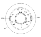
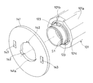
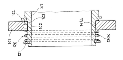
- the armature 141 prevents relative rotation with the first axis S1 when the electromagnet 144 is deenergized by meshing between the protrusion 123 provided on the first axis S1 and the notch 142 provided on the armature 141. It is done. When the electromagnet 144 is energized, this meshing is released, and the first shaft S1 and the armature 141 are in a relatively rotatable state.
- the projection 123 is provided such that a portion thereof protrudes to the outer diameter side along the circumferential direction of the outer periphery of the cylindrical portion for supporting the armature 141 in the first axis S1, and the notch 142 is The part is provided so as to be recessed along the circumferential direction of the inner circumference 141a of the hole of the axial center of the armature 141.
- the protrusion 123 is provided on the outer circumference of the first axis S1.
- a portion of the flange portion is provided so as to protrude in the axial direction from the side surface (surface facing in the axial direction), and the notch 142 is partially recessed in the side surface (surface facing in the axial direction) of the armature 141 Aspects provided as such are also conceivable.
- the protrusions 123 and the corresponding notches 142 can be provided at a plurality of locations (three locations in the embodiment) along the circumferential direction, as shown in FIGS. 9 and 12, but can exhibit the function of preventing relative rotation. In this case, at least one protrusion 123 and the corresponding notch 142 may be provided at any one of the circumferential positions.
- the projection 123 is provided on the first axis S1, and the notch 141 corresponding to this is provided on the armature 141 to exhibit the relative rotation preventing function, so that the projection 123 can be used during forging of the first axis S1.
- the projection 123 can be molded at the same time.
- the projection 123 can be formed of a member integral with the first axis S1, there is no particular limitation in setting of the thickness, and securing of the strength is easy.
- the protrusion 123 and the notch 142 may be interchanged, and the notch 142 may be provided on the first axis S1 and the protrusion 123 may be provided on the armature 41.
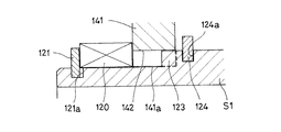
- the separating spring 120 is supported between the armature 141 and the locking portions 121 and 122 provided on the first axis S1.
- One end of the separating spring 120 is supported by the locking portions 121 and 122, and the other end of the separating spring 120 is supported by the armature 141, and is elastically tensioned in the direction of separating the locking portions 121 and 122 from the armature 141. It is a structure.
- the locking portion 121 is a locking ring fitted to the first shaft S1.
- the retaining ring 121 is a locking ring fitted to the first shaft S1.
- the cylindrical portion for supporting the armature 141 in the first axis S1 has a snap ring groove 121a at an end on one end side in the axial direction, and the snap ring 121 is inserted into the snap ring groove 121a.
- a C-shaped member in which one portion of the annular member is divided is adopted as the retaining ring 121.
- the separating spring 120 Since the separating spring 120 is disposed between the side surface of the retaining ring 121 and the side surface of the armature 141, the separating spring 120 bears the reaction force on the retaining ring 121, and the armature 141 is held by its elastic force. It always presses in the direction away from the rotor 145 (the other end side in the axial direction).
- the separating spring 120 separates the armature 141 and the rotor 145, when the armature 141 and the rotor 145 rotate relative to each other, the first shaft S1 and the separating spring 120, the separating spring 120, and the armature 141 Since there is no sliding part between them, it is possible to prevent the occurrence of wear of the members.
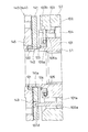
- the roller 104 of the two-way clutch 110 is against the cylindrical surface 102 a of the outer member 102 and the cam surface 101 a of the inner member 101 as shown in FIG. Is held in the neutral position for disengaging. That is, the roller 104 is located near the center of the cam surface 101a (near the center with respect to the circumferential direction), and the two-way clutch 110 is in the disengaged state.
- the rotation transmission device may use either the first axis S1 or the second axis S2 as the input side.
- the rotation in the case where the first shaft S1 is connected to the input shaft S1 ′ and used, when the first shaft S1 rotates in a state where the two-way clutch 110 is disengaged, the rotation is The first axis S1 and the inward member 1 are free rotated without being transmitted to the two axes S2 (see FIG. 10).
- the rotation of the inner member 101 is transmitted to the holder 103 via the switch spring 105, and the holder 103 and the roller 104 rotate together. Further, since the armature 141 is detentated by the holder 103, the armature 141 also rotates.
- the armature 141 moves in the axial direction toward the rotor 145, the meshing between the projection 123 and the notch 142 is released, and the armature 141 is in a state of being able to rotate relative to the first axis S1.
- the rotor 145 is connected to the outer member 102 through the cylindrical body 147, so the holder 103 is connected to the outer member 102 by adsorption of the armature 141, and the holder 103 and the inner member 101 rotate relative to each other.
- the holder 103 rotates relative to the first axis S1 (inner member 101) together with the armature 141.
- the movement of the armature 141 in the axial direction is guided by the projecting portion 103 d provided on the holder 103.
- the projecting piece portion 103 d is axially slidably inserted in the detent hole 143 provided in the armature 141, so that the projecting piece portion 103 d advances and retracts in the detent hole 143 as the armature 141 moves in the axial direction. By doing this, the axial movement of the armature 141 is guided.
- a connector (not shown) to which a wire for supplying electricity is connected is attached to the end wall 112 of the housing 111, and a brush provided on the connector and an annular contact provided on the rotor 145 The electric coil 146 is supplied with electricity by the contact of
- the relative rotation between the holder 103 and the inward member 101 causes the roller 104 to engage with the cylindrical surface 102a of the outward member 102 and the cam surface 101a of the inward member 101, and the two-way clutch 110 is engaged.
- the rotation of the inward member 101 is transmitted to the outward member 102, and the second shaft S2 is rotated.
- FIG. 13A to 13C show a specific configuration of the separation spring 120 used in each of the above embodiments.
- a disc spring 120 a is employed as the separation spring 120.
- a plurality of disc springs 120a may be arranged along the axial direction.
- the wave spring 120 b is adopted as the separation spring 120.
- a coil spring 120c is adopted as the separation spring 120.
- the separating spring 120 one having various configurations can be adopted.
- a fourth embodiment is shown in FIG.
- a recess provided in the first shaft S1 is employed as the locking portion 122 for supporting the separation spring 120 on the first shaft S1.
- a concave portion 122 it is referred to as a concave portion 122.
- the separating spring 120 Since the separating spring 120 is disposed between the side surface at one end in the axial direction in the recess 122 and the side surface of the armature 141, the separating spring 120 bears a reaction force on the side surface in the recess 122, The elastic force can always press the armature 141 in the direction (the other axial end side) away from the rotor 145.
- the recess 122 can be formed on the outer periphery of the first axis S1, there is an advantage that it is not necessary to attach a separate member as in the case where the snap ring 121 is adopted.
- the recess 122 also has an advantage that it can be formed simultaneously with the forging of the first axis S1.
- shaft S1 is employable as the latching
- the convex portion is formed of a member integral with the member constituting the first axis S1, there is also an advantage that it is not necessary to attach another member to the first axis S1.
- the convex portion has an advantage that it can be simultaneously formed at the time of forging of the first axis S1.
- the convex portion may be intermittent along the circumferential direction of the outer periphery of the first axis S1 as long as the separation spring 120 is locked, or may be continuous along the circumferential direction of the outer periphery It may be one.
- the convex portion may be a ridge extending over the entire outer periphery of the first axis S1.
- the separating spring 120 is expanded in diameter by the centrifugal force accompanying the high speed rotation depending on its structure, and predetermined performance is obtained. In some cases it can not be demonstrated. For this reason, it is desirable to properly select one of the plurality of types of disjunction springs 120 according to the range of rotation speed (centrifugal force) in which the rotation transmission device is used.
- a coil spring can be adopted as the separation spring 120 in a rotation transmission device used in a low rotation range where the centrifugal force is relatively small.
- Coil springs have the advantage of low cost.
- a disc spring can be adopted as the separation spring 120 in the rotation transmission device used in the high rotation range where the centrifugal force is relatively large.
- the disc spring may have a relatively high cost, but can exert predetermined performance even under a large centrifugal force.
- a wave spring can be employed as the separation spring 120 in an intermediate region between the high rotation region and the low rotation region. The wave spring can exert an intermediate performance between the coil spring and the disc spring in the resistance to centrifugal force, and is similar in cost.
- the separation spring 120 can be easily locked in the recess 122.
- a wave spring or a disc spring a notch is provided in a part of the annular member in the circumferential direction, and the outer diameter of the annular member changes with expansion and contraction of the width of the notch. .
- the wave spring or disc spring changes its outer diameter with respect to the shaft to which it is attached (expansion), and is fitted into the recess 122, and after being fitted, is returned to the original outer diameter and fixed .
- the two-way clutch 110 is configured between the inward member 101 provided on the first shaft S1 and the outward member 102 provided on the second shaft S2, and the outward member 102 is configured.
- a cylindrical surface 102a is provided on the inner periphery of the cam and a cam surface 101a is provided on the outer periphery of the inward member 101.
- a configuration in which the cam surface 101a is reversed inside and outside can be adopted.
- the two-way clutch 110 has a cylindrical surface 101 a ′ on the outer periphery of the member 101 and a cam surface 102 a ′ on the inner periphery of the outer member 102.
- the elastic member 120 is disposed on the inner periphery of the second axis S2, there is an advantage that it is not necessary to consider the deformation of the elastic member 120 due to the centrifugal force.
- the second shaft S2 is fixed to the electromagnet 144, the armature 141 is supported movably in the axial direction with respect to the first shaft S1, and the locking portions 121 and 122 for locking the separating spring 120 are the first shaft S1.
- the same points are provided to the
- the first shaft S1 is fixed to the electromagnet 144, the armature 141 is supported movably in the axial direction with respect to the second shaft S2, and the locking portions 121 and 122 for locking the separating spring 120 are the second
- shaft S2 is also considered.
- the locking portions 121 and 122 are provided on the second axis S2, the locking portions 121 and 122 can be provided on the outer periphery of the second axis S2.
- the locking portions 121 and 122 may be configured to be provided on the inner periphery of the second shaft S2.
- the locking portions 121 and 122 provided on the inner periphery of the second shaft S2 include, for example, a retaining ring 121 fitted on the inner periphery of the second shaft S2 and a convex integrally provided on the inner periphery of the second shaft S2.
- a concave portion 122 or the like provided on the inner circumference of the second shaft S2 can be employed.
- FIG. 16 a sixth embodiment is shown in FIG. In the embodiment of FIG. 16, the first shaft S1 and the second shaft S2 are engaged and released only by the electromagnetic clutch 140 without using the two-way clutch 110.
- the electromagnetic clutch 140 includes an armature 141 axially movable with respect to the first axis S1 or the second axis S2, an electromagnet 144 rotatable about the axis with respect to the armature 141 and axially facing the armature 141, and an armature And a separating spring 120 for urging the 141 in a direction away from the electromagnet 144.
- the armature 141 is axially movable with respect to the first axis S1, and the electromagnet 144 is supported so as to be rotatable around the first axis S1.
- the armature 141 and the first axis S1 are supported movably in the axial direction by engagement by splines indicated by reference numerals 148 and 126 in the figure, or by engagement of a convex portion and a concave portion provided along the circumferential direction, etc. Further, the armature 141 and the first axis S1 are integrally rotatable around the axis.
- the separation spring 120 is supported by locking portions 121 and 122 provided on a first axis S ⁇ b> 1 that supports the armature 141 so as to be movable in the axial direction. Therefore, the separation spring 120 is rotatable with respect to the electromagnet 144.
- the concave portion 122 is adopted as the locking portion 121, 122, but it is fixed to the convex portion integrally formed with the shaft as the locking portion 121, 122 or to the shaft as in the above embodiment. Retaining ring 121 grade
- the armature 141 is axially movable with respect to the second axis S2, and the electromagnet 144 is supported so as to be rotatable about the second axis S2.
- the locking portions 121 and 122 for supporting the separating spring 120 are provided on the second axis S2.
- the first axis S1 is the input side and the second axis S2 is the output side
- the first axis S1 is the output side
- the second axis S2 is the input side by reversing this. It is also good.
- the specification of the two-way clutch 110 is not limited to the above-described embodiment, and various clutches that can control engagement and release by the electromagnetic clutch 140 are adopted. be able to.
- the configuration of the spring end storage groove 34 used in the second embodiment can be adopted.
- the spring end storage groove 34 is provided on the inner diameter side of the suction surface of the armature 21 to the rotor 22, and the end of the separation spring 120 supported by the armature 141 is stored in the spring end storage groove 34.
Landscapes
- Engineering & Computer Science (AREA)
- General Engineering & Computer Science (AREA)
- Mechanical Engineering (AREA)
- Physics & Mathematics (AREA)
- Electromagnetism (AREA)
- Arrangement And Mounting Of Devices That Control Transmission Of Motive Force (AREA)
Abstract
離反ばね(24)の一端部をアーマチュア(21)のロータ(22)との吸着面に接触させて支持するとともに、ロータ(22)に近接する他端部を、内輪(2)の小径軸部の係合溝(31)にはめ込んだ止め輪(33)で支持する回転伝達装置を採用する。内輪(2)とアーマチュア(21)とは電磁クラッチの通電解除時に一体に回転することから、離反ばね(24)両端を支持する部材の間に回転差が生じることはないので、離反ばね(24)の片方の端部がロータ(22)に接触して支持されている場合とは異なり、回転差により離反ばね(24)に磨耗が生じることはない。
Description
本発明は、動力伝達経路における動力の伝達と遮断の切り換えに用いられる回転伝達装置に関する。
回転伝達装置として、特許文献1に記載されているように、2方向クラッチと電磁クラッチとを組み合わせた装置が知られている。この種の回転伝達装置は、入力側部材としての内方部材の外側に、出力側部材としての外方部材を設け、その内方部材と外方部材の間に2方向クラッチを組込み、その2方向クラッチのトルク伝達状態とトルク遮断状態との切り替えを電磁クラッチにより制御するようにしている。
ここで、2方向クラッチは、内方部材の外周に、外方部材の内周に形成された円筒面との間でくさび形空間を形成するカム面を設け、そのカム面と円筒面との間に組込まれた係合子としてのローラを、保持器で保持する構成を採用している。
その保持器には、スイッチばねのばね力が付与されて、ローラのカム面および円筒面に対する噛みこみが解除される中立位置に保持器を弾性的に保持している。
その保持器には、スイッチばねのばね力が付与されて、ローラのカム面および円筒面に対する噛みこみが解除される中立位置に保持器を弾性的に保持している。
また、電磁クラッチは、電磁石に対する通電により、保持器に対して回り止めされ、かつ軸方向にスライド可能に支持されたアーマチュアを、外方部材に回り止めされたロータに吸着して、保持器を外方部材に対して結合可能な構成を採用している。
いま、電磁石に通電すると、ロータに吸着したアーマチュアには、回転方向の摩擦抵抗が生じ、このアーマチュアに回り止めされた保持器が、内方部材に対し相対回転するため、中立位置から変位する。保持器に保持されたローラは、保持器の変位に伴なって円筒面およびカム面に噛みこむため、2方向クラッチはトルク伝達状態となって、内方部材の回転がローラを介して外方部材へと伝達されることになる。
一方、電磁石に対する通電を解除すると、アーマチュアのロータに対する吸着力は消失する。この際に、アーマチュアをロータから速やかに離反させるために、離反ばねのばね力が利用されている。
ロータとアーマチュアとの接触に伴なう摩擦抵抗から解放された保持器は、スイッチばねのばね力により中立位置に戻される。したがって、保持器に保持されたローラの円筒面およびカム面に対する噛みこみが解除され、2方向クラッチはトルク遮断状態となって内方部材が空転することになる。
ロータとアーマチュアとの接触に伴なう摩擦抵抗から解放された保持器は、スイッチばねのばね力により中立位置に戻される。したがって、保持器に保持されたローラの円筒面およびカム面に対する噛みこみが解除され、2方向クラッチはトルク遮断状態となって内方部材が空転することになる。
ところで、従来のこの種の回転伝達装置では、電磁クラッチにおける電磁石の通電解除時に、アーマチュアのロータからの離反を補助する離反ばねは、その一端部がアーマチュアのロータとの吸着面に接触することで支持され、その他端部がロータのアーマチュアとの対向面に接触することで支持されていた。
このような構成を採用した場合、2方向クラッチをトルク伝達状態からトルク遮断状態に切り替える際、ともに高速回転している内方部材から外方部材への動力の伝達が遮断されることで、内方部材と一体に回転するアーマチュアと外方部材と一体に回転するロータとの間に大きな回転差が生じる。
したがって、両端部がアーマチュアとロータにそれぞれ支持されている離反ばねは、この回転差により摩耗することが懸念される。特に、想定を超えるような高速回転が発生すると、これらの接触部での摺動により、部材の摩耗が発生する可能性がある。離反ばねのばね力が低下すると、電磁クラッチにおける電磁石の通電を解除した場合にも、アーマチュアがロータから離れにくくなるため、2方向クラッチにおけるトルク伝達状態とトルク遮断状態との切り替えがスムーズに行われなくなるおそれがある。
また、特許文献1の回転伝達装置では、入力側の高速回転時におけるミス係合対策のため、内輪(入力軸)に固定された止め輪に設けた突起により、中立状態において、アーマチュアが回転することを防止する構造としている。
しかし、この構造では、止め輪の突起によって、アーマチュアの回転を固定しているため、突起自体の肉厚を厚くすることが難しいという問題がある。このため、同じく、想定を超えるような高速回転が発生した場合には、突起の変形が発生する可能性があることから、許容できる回転速度には限界があった。
そこで本発明の解決すべき課題は、2方向クラッチと電磁クラッチとを組み合わせて、動力の伝達と遮断の切り換えをおこなう回転伝達装置において、離反ばねとの接触による部材の摩耗を抑えることを第一の課題とし、アーマチュアの回転を固定する手段をより強固にすることを第二の課題とする。
上記第一の課題を解決するため、発明にかかる回転伝達装置を、内方部材と、前記内方部材の外側に、前記内方部材と同軸上に配置された外方部材と、前記内方部材から前記外方部材へと、正逆両方向への回転トルクを伝達するトルク伝達状態と回転トルクを遮断するトルク遮断状態との間で切り替え可能な2方向クラッチと、前記2方向クラッチの作動時と非作動時との切り替えを制御する電磁クラッチと、を備えるものとしたのである。
そして、前記2方向クラッチは、前記内方部材の外径面と前記外方部材の内径面の間に配置された係合子と、前記係合子を保持する保持器と、前記保持器を中立位置に付勢するスイッチばねと、を有するものとしたのである。ここで、前記2方向クラッチは、前記トルク伝達状態のときには、前記保持器が前記スイッチばねの付勢に抗して中立位置から変位することで、前記係合子が前記内方部材と前記外方部材の対向面間に噛みこみ、前記トルク遮断状態のときには、前記保持器は前記スイッチばねの付勢により中立位置に復帰することで、前記係合子の前記内方部材と前記外方部材の対向面間への噛みこみは解除されるものとする。
そして、前記2方向クラッチは、前記内方部材の外径面と前記外方部材の内径面の間に配置された係合子と、前記係合子を保持する保持器と、前記保持器を中立位置に付勢するスイッチばねと、を有するものとしたのである。ここで、前記2方向クラッチは、前記トルク伝達状態のときには、前記保持器が前記スイッチばねの付勢に抗して中立位置から変位することで、前記係合子が前記内方部材と前記外方部材の対向面間に噛みこみ、前記トルク遮断状態のときには、前記保持器は前記スイッチばねの付勢により中立位置に復帰することで、前記係合子の前記内方部材と前記外方部材の対向面間への噛みこみは解除されるものとする。
また、前記電磁クラッチは、前記内方部材に軸方向にスライド可能に嵌合され、かつ前記保持器に回り止めされたアーマチュアと、前記外方部材に回り止めされて前記アーマチュアと軸方向に対向するロータと、前記アーマチュアを前記ロータから離反する方向に付勢する離反ばねと、前記ロータと軸方向に対向し、通電により前記ロータに前記アーマチュアを吸着させ、通電遮断により前記ロータへの前記アーマチュアの吸着を解除する電磁石と、を有するものとしたのである。ここで前記電磁クラッチは、前記電磁石の通電時には、前記アーマチュアの前記ロータへの吸着により、アーマチュアに回り止めされた前記保持器はロータからの回転抵抗を受けて前記中立位置から変位し、前記電磁石の通電遮断時には、前記離反ばねの付勢により前記アーマチュアは前記ロータから離反して、ロータからの回転抵抗から解放された前記保持器は前記スイッチばねの付勢で前記中立位置へと復帰するものとする。
さらに、前記離反ばねは、その一端部が前記アーマチュアのロータへの吸着面に支持されており、その他端部が前記内方部材の外周に形成されたばね受け凸部に支持されているものとしたのである。
発明にかかる回転伝達装置では、離反ばねのロータに近接する側の端部が、内方部材の外周に形成されたばね受け凸部に支持されているところ、内方部材とアーマチュアとは電磁クラッチの通電解除時に一体に回転することから、離反ばねの両端を支持する部材の間に回転差が生じることはない。したがって、離反ばねの片方の端部がロータに接触して支持されている場合とは異なり、回転差により離反ばねに磨耗が生じることはない。
このため、離反ばねのばね力が長期にわたって維持され、電磁石の通電を解除した場合に、アーマチュアがロータから速やかに離反し、内方部材から外方部材への動力の遮断がスムーズに行われる。
発明にかかる回転伝達装置では、前記内方部材のばね受け凸部は、前記内方部材の外周に外嵌された止め輪である構成を採用するのが好ましい。
このようにすると、安価かつ簡単にばね受け凸部を形成することができる。
このようにすると、安価かつ簡単にばね受け凸部を形成することができる。
また、上記第一の課題を解決するために、この発明は、同軸上に配置された第1軸と第2軸とを係合及び解除する電磁クラッチを備え、前記電磁クラッチは、前記第1軸又は前記第2軸に対して軸方向移動自在のアーマチュアと、前記アーマチュアに対して軸回り回転自在で前記アーマチュアと軸方向で対向する電磁石と、前記アーマチュアを前記電磁石から離反する方向へ付勢する離反ばねと、を備え、前記弾性部材は、前記電磁石に対して回転自在で前記アーマチュアを軸方向移動自在に支持する前記第1軸又は前記第2軸に設けられた係止部で支持されている回転伝達装置を採用した。
ここで、前記電磁クラッチは、前記第1軸と前記第2軸との係合及び解除を2方向クラッチによって制御し、前記2方向クラッチは、前記第1軸に設けられた内方部材と、前記第2軸に設けられた外方部材と、前記内方部材と前記外方部材との間に組み込まれた保持器と、前記保持器に保持され前記内方部材に対する前記保持器の相対回転により前記内方部材及び前記外方部材の一方に設けられた円筒面と他方に設けられたカム面との間に係合するローラと、前記ローラが係合解除される中立位置に前記保持器を付勢する中立保持用弾性部材と、を備える構成を採用することができる。
また、上記第二の課題を解決するために、この発明は、上記の構成において、前記アーマチュアは、前記係止部が設けられた前記第1軸又は前記第2軸及び前記アーマチュアの一方に設けられた突起と他方に設けた切欠きとの噛合いにより、前記電磁石への非通電時に前記係止部が設けられた前記第1軸又は前記第2軸と前記アーマチュアとの相対回転を防止する構成を採用した。
ここで、前記一方は前記係止部が設けられた前記第1軸又は前記第2軸であり、前記他方は前記アーマチュアである構成を採用することができる。すなわち、前記突起は前記第1軸又は前記第2軸に、前記切欠きは前記アーマチュアに設けられた構成を採用することができる。
これらの各態様において、前記係止部は、前記第1軸又は前記第2軸に嵌合した止め輪である構成を採用することができる。あるいは、前記係止部は、前記第1軸又は前記第2軸に一体に設けられた凸部である構成を採用することができる。さらには、前記係止部は、前記第1軸又は前記第2軸に設けた凹部である構成を採用することができる。
これらの各態様において、前記離反ばねは、コイルスプリングである構成を採用することができる。あるいは、前記弾性部材は、ウェーブスプリングである構成を採用することができる。さらには、前記弾性部材は、皿ばねである構成を採用することができる。
これらの各態様において、前記アーマチュアは、前記ロータへの吸着面に、前記離反ばねの一端部が格納されるばね端格納溝を有している構成を採用することができる。このようにすると、アーマチュアの回転に伴ない、離反ばねに遠心力が生じるなどしても、ばねの端部がばね端格納溝に格納されて位置決めされていることから、アーマチュアの径方向にずれ動くことが防止される。したがって、離反ばねの片当りなどに伴なう、偏荷重の負荷が抑制され、破損を防止することができる。
発明にかかる回転伝達装置を以上のように構成したので、離反ばねとの接触による部材の摩耗を抑えることができる。また、アーマチュアの回転を固定する手段をより強固なものにすることができる。
以下、図面を参照しつつ本発明の実施形態について説明する。
図1から図4に示す、第一の実施形態の回転伝達装置では、ハウジング1内に内方部材2としての内輪(以下、内輪2と称する)が組込まれている。この内輪2は、カムリング3を軸方向の中央部に有し、そのカムリング3の両端に一対の小径軸部4,5を設けた構成とされている。
内輪2の内径面には、スプライン2aが形成されており、ここに図示省略の入力軸が嵌合されている。また、内輪2の内径面には、シール2bが設けられている。
内輪2の内径面には、スプライン2aが形成されており、ここに図示省略の入力軸が嵌合されている。また、内輪2の内径面には、シール2bが設けられている。
内輪2の外側には外方部材6としての外輪(以下、外輪6と称する)6が設けられ、その外輪6と内輪2は軸受7を介して相対的に回転自在に支持されている。また、外輪6はハウジング1内に組込まれた軸受8を介して回転自在に支持されている。外輪6とハウジング1の開放端との間には、シール9が設けられている。
外輪6の内径面には、スプライン6aが形成されており、ここに図示省略の出力軸が嵌合されている。入力軸とハウジング1の間は、オイルシール1aにより閉塞されている。
外輪6の内径面には、スプライン6aが形成されており、ここに図示省略の出力軸が嵌合されている。入力軸とハウジング1の間は、オイルシール1aにより閉塞されている。
内輪2と外輪6との間には2方向クラッチ10が設けられ、その2方向クラッチ10の作動および非作動を制御する電磁クラッチ20が上記2方向クラッチ10と回転伝達装置の軸方向に隣接して並設されている。
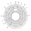
図3に示すように、2方向クラッチ10は、外輪6の内径面に円筒面11を形成し、カムリング3の外径面には円筒面11との間でくさび形空間を形成する複数のカム面12を周方向に間隔をおいて設け、各カム面12と円筒面11間に係合子としてのローラ13を組込み、そのローラ13を内輪2と外輪6の間に組込まれた保持器14で保持したローラクラッチからなる。
内輪2と保持器14の相互間には、ローラ13が円筒面11およびカム面12に対して係合解除される中立位置に保持器14を弾性保持するためのスイッチばね15が組込まれている。
このスイッチばね15は、C形リング部15aの両端に一対の押圧片15bを外向きに形成した構成とされている。
このスイッチばね15は、C形リング部15aの両端に一対の押圧片15bを外向きに形成した構成とされている。
図2および図3に示すように、スイッチばね15は、カムリング3の端面に形成されたばね収納凹部16内にC形リング部15aが嵌合される組付けとされている。
一対の押圧片15bは、ばね収納凹部16の周壁に形成された切欠き部17を通じて保持器14の端面に設けられた切欠き18内に挿入されている。これにより、スイッチばね15は、切欠き部17および切欠き18の周方向で対向する端面を相反する方向に押圧し、ローラ13を中立位置に保持している。
一対の押圧片15bは、ばね収納凹部16の周壁に形成された切欠き部17を通じて保持器14の端面に設けられた切欠き18内に挿入されている。これにより、スイッチばね15は、切欠き部17および切欠き18の周方向で対向する端面を相反する方向に押圧し、ローラ13を中立位置に保持している。
スイッチばね15は、内輪2の小径軸部5に嵌合されたばね押え19により、軸方向に固定されている。ばね押え19は、保持器14と係合することで保持器14に対して回り止めされている。
図1および図2に示すように、電磁クラッチ20は、内輪2の小径軸部5にスライド自在に嵌合されて保持器14の端面と軸方向で対向するアーマチュア21と、そのアーマチュア21と軸方向で対向するロータ22と、そのロータ22と軸方向で対向する電磁石23と、アーマチュア21をロータ22から離反する方向に押圧する離反ばね24とからなる。
図1および図2に示すように、アーマチュア21には係合孔25が形成され、その係合孔25にばね押え19の外縁に設けられた突片26が挿入されている。
その突片26と係合孔25の係合によって、アーマチュア21はばね押え19を介して保持器14に対して回り止めされ、かつ、軸方向にスライド可能となっている。
その突片26と係合孔25の係合によって、アーマチュア21はばね押え19を介して保持器14に対して回り止めされ、かつ、軸方向にスライド可能となっている。
図1に示すように、ロータ22は、内周および外周に円筒部22a、22bを有し、外周の円筒部22bが外輪6の開口端部内に取付けられた非磁性体から成るロータガイド27内に圧入されて外輪6に回り止めされている。
ロータ22の内側の円筒部22aの内径面には、図示省略の入力軸を回転可能に支持するための軸受22cが設けられている。
ロータ22の内側の円筒部22aの内径面には、図示省略の入力軸を回転可能に支持するための軸受22cが設けられている。
電磁石23は、フィールドコア23aと、そのフィールドコア23aに支持された電磁コイル23bから成る。この電磁石23は、ロータ22の内外の円筒部22a、22bの間に配置され、そのフィールドコア23aがハウジング1の閉塞端に非回転に支持されている。フィールドコア23aとハウジング1の間には、ワッシャ29が介在している。
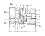
図2に示すように、内輪2の一端側の小径軸部5には、係合溝30および係合溝31が二列に形成されており、それぞれ止め輪32及び止め輪33が嵌め込まれている。
カムリング3に近い側の止め輪32は、アーマチュア21がロータ22から離反した際に当接してその離反量を制限するものである。また、カムリング3から遠い側の止め輪33は、後述するように離反ばね24の端部を支持するものである。
カムリング3に近い側の止め輪32は、アーマチュア21がロータ22から離反した際に当接してその離反量を制限するものである。また、カムリング3から遠い側の止め輪33は、後述するように離反ばね24の端部を支持するものである。
図2のように、離反ばね24は、アーマチュア21とロータ22との間に設けられている。離反ばね24の両端部のうち一端部は、アーマチュア21のロータ22への吸着面に接触することで支持されている。また、離反ばね24の他端部は、ばね受け凸部としての止め輪33に接触することで支持されている。図示のように、離反ばね24とロータ22とは、非接触の状態にある。
実施形態の回転伝達装置の構成は以上のようであり、電磁石23の電磁コイル23bに対する通電の遮断状態では、図3のように、スイッチばね15のばね力によりローラ13は中立状態に保持されるため、内輪2の回転は外輪6に伝達されず、2方向クラッチはトルク遮断状態となって、内輪2が空転する。
このような内輪2の空転状態から、電磁石23の電磁コイル23bに通電すると、アーマチュア21に吸引力が付与され、アーマチュア21は離反ばね24の弾性に抗して軸方向にスライドして、図4に示すように、ロータ22に吸着される。
ロータ22とアーマチュア21の吸着面に作用する摩擦抵抗は保持器14の回転抵抗となるが、その摩擦抵抗は、スイッチばね15のばね力より予め大きな値に設定されている。このため、スイッチばね15は弾性変形して、内輪2と保持器14とが相対回転する。その相対回転により、保持器14は中立位置から変位し、ローラ13がくさび形空間の狭小部に押し込まれて円筒面11およびカム面12に噛みこむ。したがって、2方向クラッチはトルク伝達状態となって、内輪2の回転はローラ13を介して外輪6に伝達されることになる。
このような内輪2から外輪6へのトルク伝達状態から、電磁コイル23bに対する通電を遮断すると、離反ばね24の押圧により、アーマチュア21はロータ22から離反して、図2に示すように、止め輪32に当接する位置まで移動する。
また、アーマチュア21がロータ22から離反すると、スイッチばね15のばね力により保持器14が内輪2に対して係合時の逆方向に回転され、ローラ13は円筒面11およびカム面12への噛みこみが解除されて中立位置に復帰する。このため、内輪2から外輪6への回転伝達が遮断される。
内輪2から外輪6への回転伝達が遮断されると、内輪2と外輪6との間に回転差が生じ、内輪2と一体に回転するアーマチュア21と外輪6と一体に回転するロータ22との間にも回転差が生じることになる。
離反ばね24の両端部がアーマチュア21とロータ22にそれぞれ支持されている場合、その両端部における回転差により離反ばね24が摩耗し、ばね力が低下してしまう恐れがあるが、本実施形態では、離反ばね24の両端部は内輪2に設けられた止め輪33と内輪2と一体に回転するアーマチュア21にそれぞれ支持されているため、離反ばね24の両端部間に回転差が生じず、摩耗を抑制することができる。したがって、離反ばね24のばね力の低下が防止され、2方向クラッチ10の応答性がよく、信頼性の高い回転伝達装置を得ることができる。
図5に、第二の実施形態の回転伝達装置を示す。
この実施形態では、アーマチュア21のロータ22への吸着面の内径側にばね端格納溝34が設けられており、離反ばね24のアーマチュア21に支持される側の端部が、このばね端格納溝34に格納されている。
この実施形態では、アーマチュア21のロータ22への吸着面の内径側にばね端格納溝34が設けられており、離反ばね24のアーマチュア21に支持される側の端部が、このばね端格納溝34に格納されている。
内輪2が回転すると、内輪2と一体的に回転するアーマチュア21に支持される離反ばね24の端部には、遠心力が生じるなどして、アーマチュア21の径方向にずれ動きやすくなるが、その端部がばね端格納溝34に格納されることで、径方向へのずれ動きが防止される。
このように、離反ばね24がアーマチュア21に対してずれ動かないように位置決めすることで、片当たり状態が発生するなどして離反ばね24に偏荷重が負荷される事態が防がれ、その破損が防止される。したがって、離反ばね24のばね力の低下が一層防止され、一層信頼性の高い回転伝達装置を得ることができる。
上記の各実施形態では、離反ばね24のアーマチュア21に支持される側の逆側の端部を支持するためのばね受け凸部の一例として止め輪を示したが、これに限定されず、たとえば内輪2の外径面に一体に形成されたばね受け凸部としてもよい。また、ばね受け凸部は内輪の外径面の全周に設ける必要はなく、断続的に設けたり、一部に設けたりしてもよい。
上記の各実施形態では、内方部材や外方部材の一例として、入力軸や出力軸と別体の内輪と外輪を示したが、これに限定されず、内方部材や外方部材を入力軸や出力軸と一体としてもよい。上記の各実施形態では、2方向クラッチの係合子の一例として、ローラを示したが、これに限定されず、ボール等でもよい。
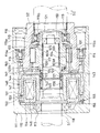
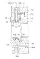
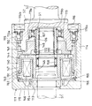
図6~図13Cに、第三の実施形態の回転伝達装置を示す。この第三の実施形態の回転伝達装置は、第1軸S1と、その第1軸S1と同軸上に配置された第2軸S2と、第1軸S1から第2軸S2への回転の伝達と遮断とを行なう2方向クラッチ110、及び、その2方向クラッチ110の係合、解除を制御する電磁クラッチ140とを備えている。2方向クラッチ110が係合すると第1軸S1から第2軸S2への回転の伝達が可能となり、2方向クラッチ110の係合が解除されると第1軸S1から第2軸S2への回転の伝達が遮断される。
この実施形態では、第1軸S1は入力側であり、その第1軸S1の軸心に設けた孔に入力軸S1’が挿通され、セレーションやスプライン等の結合手段117等を介して、第1軸S1と入力軸S1’とは一体回転可能となっている。また、第2軸S2は出力側であり、その第2軸S2の端部の軸心に設けた孔に出力軸S2’が挿通され、第2軸S2と出力軸S2’とは一体回転可能となっている。なお、第1軸S1と入力軸S1’、あるいは、第2軸S2と出力軸S2’は、それぞれ一体の部材で構成した態様も考えられる。
電磁クラッチ140は、第1軸S1上に設けられて2方向クラッチ110に並設され、その2方向クラッチ110および電磁クラッチ140は筒状のハウジング111によって覆われている。
入力軸S1’は、ハウジング111の端壁112に形成された軸挿入孔113に軸端部が挿入され、その軸挿入孔113内に組み込まれた軸受118、及び、電磁クラッチ140の内径側に組み込まれた軸受158等によって、ハウジング111に対して回転自在に支持されている。入力軸S1’の軸端部と第1軸S1の他端部内周間は、シール部材159によって密閉されている。
出力軸S2’は、ハウジング111の他端開口部内に組み込まれた軸受115によりハウジング111に対して回転自在で、且つ、止め輪115a,115b,150等によって軸方向へ非可動の状態で支持されている。出力軸S2’とハウジング111の他端部内周間は、シール部材116によって密閉されている。
2方向クラッチ110は、第2軸S2に設けられた環状の外方部材102と、第1軸S1に設けられて外方部材102の内側に組み込まれた内方部材101と、その内方部材101と外方部材102の対向部間に組み込まれた係合子としてのローラ104と、そのローラ104を保持する環状の保持器103等を備えた2方向ローラクラッチである。ここで、内方部材101や外方部材102は、それぞれ第1軸S1や第2軸S2と一体の部材で形成されているが、その内方部材101と第1軸S1、あるいは、外方部材102と第2軸S2をそれぞれ別部材で構成するとともに、互いにセレーションやスプライン等の結合手段により一体化してもよい。
第1軸S1には、内方部材101の軸方向の両端部にその内方部材101よりも小径の小径筒部が設けられ、第2軸S2と対向する軸方向他端側の小径筒部が、軸受119によって第2軸S2に対して相対的に回転自在に支持されている。図中の符号119a,119bで示す部材は、軸受119を第1軸S1、第2軸S2に対して軸方向へ固定する止め輪である。
内方部材101の外周には、外方部材102の内周に形成された円筒面102aとの間で周方向の両端が狭小となるくさび空間を形成する複数の平坦なカム面101aが、周方向に沿って等間隔に形成されている。各カム面101aと円筒面102aとの間に、円筒状を成すローラ104が組み込まれている。
保持器103には、内方部材101のカム面101aと径方向で対向する位置にポケット103aが形成され、そのポケット103a内にそれぞれローラ104が収容されている。ローラ104は、外周に転動面104aを有する円筒状の部材である。内方部材101に対して保持器103が相対回転した際に、ローラ104は、円筒面102a及びカム面101aに係合して第1軸S1と第2軸S2とを結合させ、その第1軸S1と第2軸S2との相互間で回転トルクを伝達する。
保持器103には、第1軸S1と対向する軸方向他端側の端部に、内向きのフランジ103cを備えている。フランジ103cが、内方部材1の軸方向他端側の小径筒部に回転自在に嵌合されている。また、フランジ103cは、内方部材1の軸方向他端側の小径筒部の外周に取り付けた止め輪125によって軸方向に位置決めされている。
内方部材101の軸方向一端側の小径筒部上には、ローラ104が円筒面102a及びカム面101aと係合解除する中立位置に、保持器103を弾性保持する中立保持用弾性部材105が設けられている。この実施形態では、中立保持用弾性部材105として、図10に示すスイッチばね(以下、スイッチばね105と称する。)を採用しているが、他の種別からなるスプリング等であってもよい。
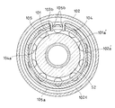
スイッチばね105は、図10に示すように、周方向の一部に切り離し端を有するリング部105aの両端に一対の係合片105bを外向きに設けた構成とされている。スイッチばね105は、リング部105aが小径筒部の外径面上に嵌め合されて内方部材101の一端面に形成された円形凹部101c内に嵌合され、一対の係合片105bが円形凹部101cの外周壁に形成された切欠部101bから保持器103の一端部に形成された切欠き103b内に挿入される。
スイッチばね105の組み込みによって、一対の係合片105bが切欠部101b及び切欠き103bの周方向で対向する両端部を相反する方向に向けて押圧する。その押圧によって保持器103はローラ104が円筒面102a及びカム面101aに対して係合解除する中立位置に弾性保持される。すなわち、スイッチばね105は、内方部材101に対する保持器103の相対回転により弾性変形した際、その弾性力によりローラ104が中立位置に維持されるように、保持器103を周方向へ付勢する。
また、保持器103の軸方向一端側の端部には、突片部103dが設けられている。突片部103dは、アーマチュア141に設けられた孔143にスライド自在に嵌合される。これにより、アーマチュア141は保持器103に対して回り止めされている。
電磁クラッチ140は、保持器103に対して回り止めされて第1軸S1に対して軸方向へ移動自在に支持されたアーマチュア141と、第1軸S1に対して軸回り回転自在に支持されてアーマチュア141と軸方向で対向する電磁石144と、アーマチュア141を電磁石144から離反する方向へ付勢する弾性部材120として離反ばね(以下、離反ばね120と称する)を備えている。
電磁石144は、磁性体からなるロータ145と、そのロータ145に保持された電磁コイル146とを備えている。ロータ145は、内筒部と外筒部とを軸方向他端側の端壁で結んだ断面コ字状の筒状部材で構成される。ロータ145の軸方向他端側の端壁がアーマチュア141と対向し、内筒部と第1軸S1との間に組み込まれた軸受158により、第1軸S1に対して相対回転自在に支持されている。また、ロータ145は、非磁性体からなる筒体147を介して、2方向クラッチ110の外方部材102に連結され、外方部材102と一体に回転する。
ここで、外方部材102と筒体147との連結は、外方部材102の軸方向一端側の端部の外径面に突出部を設け、その突出部を筒体147の軸方向他端側の端部の内径面に開口する切欠部に嵌合して、さらに、筒体147の外径面に取り付けた止め輪150によって、突出部の抜け止めとしている。
また、ロータ145と筒体147との連結は、筒体147の軸方向一端側の端部に嵌合された外筒部の一端部外径面に突出部151を設け、その突出部151を、筒体147の軸方向一端側の内径面に開口する切欠部152に嵌合し、さらに、筒体147の内径面に取り付けた止め輪153によって、突出部151の抜け止めとしている。電磁コイル146の軸方向一端は、ハウジング111に固定されたプレート154に当接して保持されている。プレート154は、止め輪155及びシム156を介して、ハウジング111に対して軸方向移動が規制された状態に固定されている。
アーマチュア141は、第1軸S1に設けられた突起123と、アーマチュア141に設けられた切欠き142との噛合いにより、電磁石144への非通電時において、第1軸S1との相対回転が防止されている。電磁石144への通電時においては、この噛合いは解除され、第1軸S1とアーマチュア141とは相対回転可能な状態となる。
この実施形態では、突起123は、第1軸S1におけるアーマチュア141を支持するための円筒部外周の周方向に沿って、その一部が外径側へ突出するように設けられ、切欠き142はアーマチュア141の軸心の孔の内周141aの周方向に沿って、その一部が凹むように設けられているが、これ以外にも、例えば、突起123は第1軸S1の外周に設けたフランジ部の側面(軸方向へ向く面)から、その一部が軸方向側へ突出するように設けられ、切欠き142はアーマチュア141の側面(軸方向へ向く面)に、その一部が凹むように設けられた態様も考えられる。
突起123とそれに対応する切欠き142は、図9や図12に示すように、周方向に沿って複数箇所(実施形態では3箇所)設けることができるが、相対回転防止の機能が発揮できるものであれば、突起123とそれに対応する切欠き142は、周方向のいずれかの箇所に少なくとも1箇所あればよい。
このように、第1軸S1に突起123を設け、アーマチュア141には、これに対応する切欠き142を設けて相対回転防止機能を発揮させたので、突起123は、第1軸S1の鍛造時に同時に成形できるという利点がある。また、突起123は、第1軸S1と一体の部材で形成できるため、肉厚の設定にあまり制限がなく強度の確保が容易である。
なお、上記の各態様において、突起123と切欠き142を入れ替えて、切欠き142を第1軸S1に、突起123をアーマチュア41に設けた態様としてもよい。
離反ばね120は、アーマチュア141と第1軸S1に設けられた係止部121,122との間で支持されている。離反ばね120の一端は係止部121,122で支持され、離反ばね120の他端はアーマチュア141で支持され、その係止部121,122とアーマチュア141との間を遠ざける方向へ弾性力で突っ張る構成である。
この第三の実施形態では、図6~図8に示すように、係止部121は、第1軸S1に嵌合した止め輪である。以下、止め輪121と称する。
第1軸S1におけるアーマチュア141を支持するための円筒部には、軸方向一端側の端部に止め輪溝121aがあり、この止め輪溝121aに止め輪121が挿入される。止め輪121には、環状部材の1箇所が分断されたC字状の部材を採用する。
この止め輪121の側面と、アーマチュア141の側面との間に離反ばね120が配置されているので、離反ばね120は、止め輪121に反力を負担させながら、その弾性力で、アーマチュア141をロータ145から離反する方向(軸方向他端側)へ常時押圧している。
電磁クラッチ140の電磁石144に対する通電が無い場合には、弾性部材120の押圧力で、アーマチュア141は第1軸S1の突起123側に押されているため、図7、図8に示すように、突起123と切欠き142とが噛合い、第1軸S1に対してアーマチュア141が回転することはなく、ローラ104の引き摺りトルクによるミス係合を防止できる。また、離反ばね120はアーマチュア141とロータ145とを離反させているものの、そのアーマチュア141とロータ145とが互いに相対回転する際に、第1軸S1と離反ばね120、離反ばね120とアーマチュア141との間には、互いに摺動する部分が無いため、部材の摩耗の発生を防止することが可能となる。
電磁クラッチ140の電磁コイル146への通電の遮断状態では、2方向クラッチ110のローラ104は、図10に示すように、外方部材102の円筒面102a及び内方部材101のカム面101aに対して係合解除する中立位置に保持されている。すなわち、ローラ104は、カム面101aの中央付近(周方向に対する中央付近)に位置し、2方向クラッチ110は係合解除状態にある。
ここで、回転伝達装置は、第1軸S1と第2軸S2のいずれを入力側として使用してもよい。この実施形態のように、第1軸S1を入力軸S1’に接続して使用する場合において、2方向クラッチ110が係合解除とされる状態で第1軸S1が回転すると、その回転は第2軸S2に伝達されず、第1軸S1および内方部材1がフリー回転する(図10参照)。
このとき、内方部材101の回転はスイッチばね105を介して保持器103に伝達されて、保持器103及びローラ104が共に回転する。また、アーマチュア141は、保持器103に回り止めされているため、アーマチュア141も回転する。
この第1軸S1のフリー回転状態において、電磁クラッチ140の電磁コイル146に通電すると、アーマチュア141が電磁石144のロータ145に磁気吸引されてロータ145の端壁にアーマチュア141が近づき、アーマチュア141はロータ145の端壁に吸着される(図11参照)。
アーマチュア141がロータ145側へと軸方向へ移動するので、突起123と切欠き142との噛合いは解除され、第1軸S1に対してアーマチュア141が相対回転可能な状態となる。ロータ145は、筒体147を介して外方部材102に連結されているため、アーマチュア141の吸着により保持器103は外方部材102に連結され、保持器103と内方部材101とが相対回転する。
これにより、保持器103は、アーマチュア141とともに、第1軸S1(内方部材101)に対して相対回転する。このとき、アーマチュア141の軸方向への移動は、保持器103に設けた突片部103dによってガイドされている。突片部103dは、アーマチュア141に設けた回り止め孔143内に軸方向へスライド自在に挿入されているので、アーマチュア141の軸方向移動とともに、その突片部103dが回り止め孔143内で進退することで、アーマチュア141の軸方向移動のガイドが行われる。
なお、ハウジング111の端壁112には、電気供給用の電線が接続されるコネクタ(図示せず)が取り付けられており、そのコネクタに設けられたブラシとロータ145に設けられた環状の接点との接触により、電磁コイル146に電気が供給されるようになっている。
保持器103と内方部材101との相対回転により、ローラ104は、外方部材102の円筒面102a及び内方部材101のカム面101aに係合し、2方向クラッチ110は係合状態となり、内方部材101の回転が外方部材102に伝達されて、第2軸S2が回転する。
保持器103と内方部材101とが相対回転した際、図10に示す切欠部101bの端面と切欠き103bの端面とが周方向に位置がずれ、スイッチばね105のリング部105aが弾性変形して縮径する。このため、電磁コイル146に対する通電を解除すると、スイッチばね105の復元弾性により保持器103が復帰回動し、ローラ104が係合解除する中立位置に戻され、2方向クラッチ110が係合解除する。その係合解除によって第1軸S1から第2軸S2への回転トルクの伝達が遮断される。
なお、図6に示す第2軸S2を入力側として使用する場合は、2方向クラッチ110の係合解除状態において、入力軸の回転によって第2軸S2が回転すると、その第2軸S2と外方部材102、筒体147及び電磁石144が共にフリー回転する。
第2軸S2のフリー回転状態において、電磁コイル146に通電すると、前述と同様に、ロータ145の端壁にアーマチュア141が吸着され、そのアーマチュア141及び筒体147を介して保持器103が外方部材102に連結される。これにより、内方部材101と保持器103とが相対回転する。この相対回転により、ローラ104は、外方部材102の円筒面102a及び内方部材101のカム面101aに係合し、2方向クラッチ110が係合状態となり、第2軸S2の回転が第1軸S1に伝達されることとなる。
図13A~図13Cに、上記の各実施形態で用いられる離反ばね120の具体的構成を示す。図13Aの例では、離反ばね120として皿ばね120aを採用している。皿ばね120aは、軸方向に沿って複数配置してよい。図13Bの例では、離反ばね120としてウェーブスプリング120bを採用している。さらに、図13Cの例では、離反ばね120としてコイルスプリング120cを採用している。このように、離反ばね120としては種々の構成のものを採用できる。
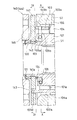
また、第四の実施形態を図14に示す。この実施形態は、離反ばね120を第1軸S1に支持する係止部122として、第1軸S1に設けた凹部を採用したものである。以下、凹部122と称する。
この凹部122内の軸方向一端側の側面と、アーマチュア141の側面との間に離反ばね120が配置されているので、離反ばね120は、凹部122内の側面に反力を負担させながら、その弾性力で、アーマチュア141をロータ145から離反する方向(軸方向他端側)へ常時押圧することができる。
凹部122は、第1軸S1の外周に形成できるので、止め輪121を採用した場合のように別部材を取り付ける必要がないという利点がある。また、凹部122は、第1軸S1の鍛造時に同時に成形できるという利点もある。
さらに、他の形態の係止部121,122として、第1軸S1に一体に設けられた凸部を採用することができる。凸部が、第1軸S1を構成する部材と一体の部材で形成されるものであれば、同じく、第1軸S1に別部材を取り付ける必要がないという利点がある。また、凸部は、第1軸S1の鍛造時に同時に成形できるという利点もある。凸部は、離反ばね120が係止されるものであれば、第1軸S1の外周の周方向に沿って断続的なものであってもよいし、外周の周方向に沿って連続的なものであってもよい。特に、凸部を、第1軸S1の外周全周に亘る突条とすることもできる。
このように、第1軸S1側に係止部121,122を設けて高速回転をさせた場合、離反ばね120は、その構造によっては高速回転に伴う遠心力で拡径し、所定の性能を発揮できない場合もあり得る。このため、その回転伝達装置が使用される回転数(遠心力)の領域に応じて、複数の種別の離反ばね120の中から最適なものを使い分けることが望ましい。
例えば、比較的遠心力が小さい低回転域で使用される回転伝達装置では、離反ばね120としてコイルスプリングを採用することができる。コイルスプリングはコストが安いという利点がある。逆に、比較的遠心力が大きい高回転域で使用される回転伝達装置では、離反ばね120として皿ばねを採用することができる。皿ばねは、比較的コストが高い場合もあるが、大きな遠心力が作用する条件下でも、所定の性能を発揮することができる。また、高回転域と低回転域との間の中間領域では、離反ばね120としてウェーブスプリングを採用することができる。ウェーブスプリングは、耐遠心力性能においてコイルスプリングと皿ばねとの間の中間的な性能を発揮することができ、また、コスト面においても同様である。
なお、係止部121,122として凹部122を採用する場合、離反ばね120として、例えば、ウェーブスプリングや皿ばねを採用すれば、その凹部122に離反ばね120を係止しやすいという利点がある。ウェーブスプリングや皿ばねとしては、その円環状の部材の周方向の一部に切欠きが設けられ、その切欠きの幅の拡縮を伴って円環状の部材の外径が変化するものを採用する。ウェーブスプリングや皿ばねは、それを取り付ける軸に対してその外径を変化(拡径)させて凹部122内へ嵌め込み、嵌め込んだ後はもとの状態の外径に復帰して固定される。
上記の各実施形態では、2方向クラッチ110は、第1軸S1に設けられた内方部材101と、第2軸S2に設けられた外方部材102との間で構成され、外方部材102の内周に円筒面102a、内方部材101の外周にカム面101aを備えた構成としたが、これを内外逆転させた構成を採用することができる。
例えば、図15に示す第五の実施形態のように、第1軸S1に設けられた内方部材101と、第2軸S2に設けられた外方部材102との間で構成され、内方部材101の外周に円筒面101a’、外方部材102の内周にカム面102a’を備えた2方向クラッチ110の構成である。この場合、弾性部材120は第2軸S2の内周に配置されるので、遠心力による弾性部材120の変形を考慮する必要がないという利点がある。電磁石144に対して第2軸S2が固定され、アーマチュア141が第1軸S1に対して軸方向移動自在に支持され、離反ばね120を係止する係止部121,122は、第1軸S1に備えられる点は同様である。
なお、電磁石144に対して第1軸S1が固定され、アーマチュア141が第2軸S2に対して軸方向移動自在に支持され、離反ばね120を係止する係止部121,122が、第2軸S2に備えられる態様も考えられる。係止部121,122が第2軸S2に備えられる場合、その係止部121,122は、第2軸S2の外周に備えられる態様とすることができる。また、筒軸で構成される部分を備えた第2軸S2の場合、係止部121,122は、第2軸S2の内周に備えられる構成とすることもできる。第2軸S2の内周に備えられる係止部121,122としては、例えば、第2軸S2の内周に嵌合した止め輪121、第2軸S2の内周に一体に設けられた凸部、第2軸S2の内周に設けた凹部122等を採用することができる。
さらに、第六の実施形態を図16に示す。図16の実施形態は、2方向クラッチ110を用いずに電磁クラッチ140のみによって、第1軸S1と第2軸S2とを係合及び解除するものである。
電磁クラッチ140は、第1軸S1又は第2軸S2に対して軸方向移動自在のアーマチュア141と、アーマチュア141に対して軸回り回転自在でそのアーマチュア141と軸方向で対向する電磁石144と、アーマチュア141を電磁石144から離反する方向へ付勢する離反ばね120とを備えている。
図16の態様では、アーマチュア141は第1軸S1に対して軸方向移動自在で、電磁石144は、第1軸S1に対して軸回り回転自在に支持されている。アーマチュア141と第1軸S1とは、図中の符号148,126に示すスプラインによる嵌合、あるいは、周方向に沿って設けた凸部と凹部との噛み合い等によって軸方向移動自在に支持され、また、アーマチュア141と第1軸S1とは軸回りに一体回転可能である。
図16に示すように、離反ばね120は、アーマチュア141を軸方向移動自在に支持する第1軸S1に設けられた係止部121,122で支持されている。このため、離反ばね120は電磁石144に対して回転自在である。ここでは、係止部121,122として凹部122を採用しているが、前述の実施形態と同様に、係止部121,122として軸と一体に形成された凸部や、軸に固定される止め輪121等を採用することもできる。
ただし、アーマチュア141が第2軸S2に対して軸方向移動自在で、電磁石144は、第2軸S2に対して軸回り回転自在に支持されている態様も考えられる。この場合、離反ばね120を支持する係止部121,122は、第2軸S2に設けられる。
また、上記の各実施形態では、第1軸S1を入力側、第2軸S2を出力側としたが、これを逆転させて、第1軸S1を出力側、第2軸S2を入力側としてもよい。また、2方向クラッチ110を用いた実施形態においては、2方向クラッチ110の仕様として、上記した実施形態には限定されず、電磁クラッチ140によって係合、解除の制御ができる種々のクラッチを採用することができる。
また、上記の第一、第三~第六の各実施形態において、第二の実施形態に用いられたばね端格納溝34の構成を採用することができる。このとき、アーマチュア21のロータ22への吸着面の内径側にばね端格納溝34が設けられ、離反ばね120のアーマチュア141に支持される側の端部が、このばね端格納溝34に格納されることになる。
今回開示された実施形態はすべての点で例示であって制限的なものではない。本発明の範囲は特許請求の範囲によって示され、特許請求の範囲内およびこれと均等の意味でのすべての修正と変形を含む。
1 ハウジング
1a オイルシール
2 内輪(内方部材)
2a スプライン
2b シール
3 カムリング
4 小径軸部
5 小径軸部
6 外輪(外方部材)
6a スプライン
7 軸受
8 軸受
9 シール
10 2方向クラッチ
11 円筒面
12 カム面
13 ローラ(係合子)
14 保持器
15 スイッチばね
15a C形リング部
15b 押圧片
16 ばね収納凹部
17 切欠き部
18 切欠き
19 ばね押え
20 電磁クラッチ
21 アーマチュア
22 ロータ
22a 円筒部
22b 円筒部
22c 軸受
23 電磁石
23a フィールドコア
23b 電磁コイル
24 離反ばね
25 係合孔
26 突片
27 ロータガイド
28 軸受
29 ワッシャ
30 係合溝
31 係合溝
32 止め輪
33 止め輪
34 ばね端格納溝
101 内方部材
101a カム面
102 外方部材
102a 円筒面
103 保持器
104 ローラ
105 中立保持用弾性部材(スイッチばね)
110 2方向クラッチ(2方向ローラクラッチ)
111 ハウジング
120 弾性部材(離反ばね)
121 係止部(止め輪)
122 係止部(凹部)
123 突起
140 電磁クラッチ
141 アーマチュア
141a 内周
142 切欠き
144 電磁石
145 ロータ
S1 第1軸
S2 第2軸
1a オイルシール
2 内輪(内方部材)
2a スプライン
2b シール
3 カムリング
4 小径軸部
5 小径軸部
6 外輪(外方部材)
6a スプライン
7 軸受
8 軸受
9 シール
10 2方向クラッチ
11 円筒面
12 カム面
13 ローラ(係合子)
14 保持器
15 スイッチばね
15a C形リング部
15b 押圧片
16 ばね収納凹部
17 切欠き部
18 切欠き
19 ばね押え
20 電磁クラッチ
21 アーマチュア
22 ロータ
22a 円筒部
22b 円筒部
22c 軸受
23 電磁石
23a フィールドコア
23b 電磁コイル
24 離反ばね
25 係合孔
26 突片
27 ロータガイド
28 軸受
29 ワッシャ
30 係合溝
31 係合溝
32 止め輪
33 止め輪
34 ばね端格納溝
101 内方部材
101a カム面
102 外方部材
102a 円筒面
103 保持器
104 ローラ
105 中立保持用弾性部材(スイッチばね)
110 2方向クラッチ(2方向ローラクラッチ)
111 ハウジング
120 弾性部材(離反ばね)
121 係止部(止め輪)
122 係止部(凹部)
123 突起
140 電磁クラッチ
141 アーマチュア
141a 内周
142 切欠き
144 電磁石
145 ロータ
S1 第1軸
S2 第2軸
Claims (13)
- 内方部材(2)と、
前記内方部材(2)の外側に、前記内方部材(2)と同軸上に配置された外方部材(6)と、
前記内方部材(2)から前記外方部材(6)へと、正逆両方向への回転トルクを伝達するトルク伝達状態と回転トルクを遮断するトルク遮断状態との間で切り替え可能な2方向クラッチ(10)と、
前記2方向クラッチ(10)のトルク伝達状態とトルク遮断状態との切り替えを制御する電磁クラッチ(20)と、を備え、
前記2方向クラッチ(10)は、
前記内方部材(2)の外径面と前記外方部材(6)の内径面の間に配置された係合子(13)と、
前記係合子(13)を保持する保持器(14)と、
前記保持器(14)を中立位置に付勢するスイッチばね(15)と、を有し、
前記電磁クラッチ(20)は、
前記内方部材(2)に軸方向にスライド可能に嵌合され、かつ前記保持器に回り止めされたアーマチュア(21)と、
前記外方部材(6)に回り止めされて前記アーマチュア(21)と軸方向に対向するロータ(22)と、
前記アーマチュア(21)を前記ロータ(22)から離反する方向に付勢する離反ばね(24)と、
前記ロータ(22)と軸方向に対向し、通電により前記ロータ(22)に前記アーマチュア(21)を吸着させ、通電遮断により前記ロータ(22)への前記アーマチュア(21)の吸着を解除する電磁石(23)と、を有し、
前記離反ばね(24)は、
その一端部が前記アーマチュア(21)の前記ロータ(22)への吸着面に支持されており、
その他端部が前記内方部材(2)の外周に形成されたばね受け凸部に支持されている、回転伝達装置。 - 前記内方部材(2)のばね受け凸部は、
前記内方部材(2)の外周に外嵌された止め輪(33)である請求項1に記載の回転伝達装置。 - 同軸上に配置された第1軸(S1)と第2軸(S2)とを係合及び解除する電磁クラッチ(140)を備え、
前記電磁クラッチ(140)は、前記第1軸(S1)又は前記第2軸(S2)に対して軸方向移動自在のアーマチュア(141)と、前記アーマチュア(141)に対して軸回り回転自在で前記アーマチュア(141)と軸方向で対向する電磁石(144)と、前記アーマチュア(141)を前記電磁石(144)から離反する方向へ付勢する離反ばね(120)と、を備え、
前記離反ばね(120)は、前記電磁石(144)に対して回転自在で前記アーマチュア(141)を軸方向移動自在に支持する前記第1軸(S1)又は前記第2軸(S2)に設けられた係止部(121,122)で支持されている回転伝達装置。 - 前記電磁クラッチ(140)は、前記第1軸(S1)と前記第2軸(S2)との係合及び解除を2方向クラッチ(110)によって制御し、
前記2方向クラッチ(110)は、前記第1軸(S1)に設けられた内方部材(101)と、前記第2軸(S2)に設けられた外方部材(102)と、前記内方部材(101)と前記外方部材(102)との間に組み込まれた保持器(103)と、前記保持器(103)に保持され前記内方部材(101)に対する前記保持器(103)の相対回転により前記内方部材(101)及び前記外方部材(102)の一方に設けられた円筒面(102a)と他方に設けられたカム面(101a)との間に係合するローラ(104)と、前記ローラ(104)が係合解除される中立位置に前記保持器(103)を付勢する中立保持用弾性部材(105)と、
を備える請求項3に記載の回転伝達装置。 - 前記アーマチュア(141)は、前記係止部(121,122)が設けられた前記第1軸(S1)又は前記第2軸(S2)及び前記アーマチュア(141)の一方に設けられた突起(123)と他方に設けた切欠き(142)との噛合いにより、前記電磁石(144)への非通電時に前記係止部(121,122)が設けられた前記第1軸(S1)又は前記第2軸(S2)と前記アーマチュア(141)との相対回転を防止する
請求項3又は4に記載の回転伝達装置。 - 前記係止部(121,122)が設けられた前記第1軸(S1)又は前記第2軸(S2)及び前記アーマチュア(141)の一方は前記係止部(121,122)が設けられた前記第1軸(S1)又は前記第2軸(S2)であり、前記係止部(121,122)が設けられた前記第1軸(S1)又は前記第2軸(S2)及び前記アーマチュア(141)の他方は前記アーマチュア(141)である
請求項5に記載の回転伝達装置。 - 前記係止部(121,122)は、前記第1軸(S1)又は前記第2軸(S2)に嵌合した止め輪(121)である
請求項3から6のいずれか一つに記載の回転伝達装置。 - 前記係止部(121,122)は、前記第1軸(S1)又は前記第2軸(S2)に一体に設けられた凸部である
請求項3から6のいずれか一つに記載の回転伝達装置。 - 前記係止部(121,122)は、前記第1軸(S1)又は前記第2軸(S2)に設けた凹部(122)である
請求項3から6のいずれか一つに記載の回転伝達装置。 - 前記離反ばね(24、120)は、コイルスプリングである
請求項1から9のいずれか一つに記載の回転伝達装置。 - 前記離反ばね(24、120)は、ウェーブスプリングである
請求項1から9のいずれか一つに記載の回転伝達装置。 - 前記離反ばね(24、120)は、皿ばねである
請求項1から9のいずれか一つに記載の回転伝達装置。 - 前記アーマチュア(21、141)は、
前記電磁石(23、144)への吸着面に、前記離反ばね(24、120)の一端部が格納されるばね端格納溝(34)を有している請求項1から12のいずれか一つに記載の回転伝達装置。
Applications Claiming Priority (4)
| Application Number | Priority Date | Filing Date | Title |
|---|---|---|---|
| JP2017-182299 | 2017-09-22 | ||
| JP2017182299A JP2019056453A (ja) | 2017-09-22 | 2017-09-22 | 回転伝達装置 |
| JP2018-001275 | 2018-01-09 | ||
| JP2018001275A JP2019120340A (ja) | 2018-01-09 | 2018-01-09 | 回転伝達装置 |
Publications (1)
| Publication Number | Publication Date |
|---|---|
| WO2019059358A1 true WO2019059358A1 (ja) | 2019-03-28 |
Family
ID=65811284
Family Applications (1)
| Application Number | Title | Priority Date | Filing Date |
|---|---|---|---|
| PCT/JP2018/035101 Ceased WO2019059358A1 (ja) | 2017-09-22 | 2018-09-21 | 回転伝達装置 |
Country Status (1)
| Country | Link |
|---|---|
| WO (1) | WO2019059358A1 (ja) |
Citations (6)
| Publication number | Priority date | Publication date | Assignee | Title |
|---|---|---|---|---|
| JPS5245725Y2 (ja) * | 1971-06-08 | 1977-10-18 | ||
| JPS5329868Y2 (ja) * | 1972-05-23 | 1978-07-26 | ||
| JPH0496626U (ja) * | 1991-01-30 | 1992-08-21 | ||
| JP2001050302A (ja) * | 1999-08-10 | 2001-02-23 | Ntn Corp | 回転伝達装置 |
| JP2004308784A (ja) * | 2003-04-07 | 2004-11-04 | Ntn Corp | 逆回転防止用クラッチユニットおよび坂道逆走行防止システム |
| JP2005307604A (ja) * | 2004-04-22 | 2005-11-04 | Ntn Corp | 自動車用電動ドア開閉装置 |
-
2018
- 2018-09-21 WO PCT/JP2018/035101 patent/WO2019059358A1/ja not_active Ceased
Patent Citations (6)
| Publication number | Priority date | Publication date | Assignee | Title |
|---|---|---|---|---|
| JPS5245725Y2 (ja) * | 1971-06-08 | 1977-10-18 | ||
| JPS5329868Y2 (ja) * | 1972-05-23 | 1978-07-26 | ||
| JPH0496626U (ja) * | 1991-01-30 | 1992-08-21 | ||
| JP2001050302A (ja) * | 1999-08-10 | 2001-02-23 | Ntn Corp | 回転伝達装置 |
| JP2004308784A (ja) * | 2003-04-07 | 2004-11-04 | Ntn Corp | 逆回転防止用クラッチユニットおよび坂道逆走行防止システム |
| JP2005307604A (ja) * | 2004-04-22 | 2005-11-04 | Ntn Corp | 自動車用電動ドア開閉装置 |
Similar Documents
| Publication | Publication Date | Title |
|---|---|---|
| US8448764B2 (en) | Rotation transmission device | |
| US8272487B2 (en) | Rotation transmission device | |
| US6257386B1 (en) | Power cut/connect device | |
| CN105934601B (zh) | 旋转传递装置 | |
| CN110945260A (zh) | 离合器以及车辆的动力传递结构 | |
| US9109642B2 (en) | Rotation transmission device | |
| EP3369958B1 (en) | Attracting arrangement for a rotation transmission device | |
| US11346403B2 (en) | Rotation braking device | |
| WO2019059358A1 (ja) | 回転伝達装置 | |
| JP7108506B2 (ja) | 回転伝達装置 | |
| JP4732200B2 (ja) | 回転伝達装置 | |
| US7086513B2 (en) | Rotation transmission device | |
| JP7262267B2 (ja) | 回転伝達装置 | |
| WO2019138933A1 (ja) | 回転伝達装置 | |
| JP2019120340A (ja) | 回転伝達装置 | |
| JP4907301B2 (ja) | 回転伝達装置 | |
| JP2019056453A (ja) | 回転伝達装置 | |
| JP2007187249A (ja) | 回転伝達装置 | |
| JP2020051530A (ja) | 回転伝達装置 | |
| WO2024043172A1 (ja) | 回転伝達装置 | |
| JP2012122563A (ja) | 係合装置 | |
| JP2020125811A (ja) | 回転伝達装置 | |
| JP2005308052A (ja) | 回転伝達装置 | |
| JP2005155659A (ja) | 回転伝達装置 | |
| JP2020003032A (ja) | 回転伝達装置 |
Legal Events
| Date | Code | Title | Description |
|---|---|---|---|
| 121 | Ep: the epo has been informed by wipo that ep was designated in this application |
Ref document number: 18859592 Country of ref document: EP Kind code of ref document: A1 |
|
| NENP | Non-entry into the national phase |
Ref country code: DE |
|
| 122 | Ep: pct application non-entry in european phase |
Ref document number: 18859592 Country of ref document: EP Kind code of ref document: A1 |