WO2019059336A1 - 油圧式オートテンショナ - Google Patents
油圧式オートテンショナ Download PDFInfo
- Publication number
- WO2019059336A1 WO2019059336A1 PCT/JP2018/034992 JP2018034992W WO2019059336A1 WO 2019059336 A1 WO2019059336 A1 WO 2019059336A1 JP 2018034992 W JP2018034992 W JP 2018034992W WO 2019059336 A1 WO2019059336 A1 WO 2019059336A1
- Authority
- WO
- WIPO (PCT)
- Prior art keywords
- cylinder
- return spring
- tensioner
- hydraulic
- cylindrical portion
- Prior art date
- Legal status (The legal status is an assumption and is not a legal conclusion. Google has not performed a legal analysis and makes no representation as to the accuracy of the status listed.)
- Ceased
Links
Images


Classifications
-
- F—MECHANICAL ENGINEERING; LIGHTING; HEATING; WEAPONS; BLASTING
- F16—ENGINEERING ELEMENTS AND UNITS; GENERAL MEASURES FOR PRODUCING AND MAINTAINING EFFECTIVE FUNCTIONING OF MACHINES OR INSTALLATIONS; THERMAL INSULATION IN GENERAL
- F16H—GEARING
- F16H7/00—Gearings for conveying rotary motion by endless flexible members
- F16H7/08—Means for varying tension of belts, ropes or chains
- F16H7/10—Means for varying tension of belts, ropes or chains by adjusting the axis of a pulley
- F16H7/12—Means for varying tension of belts, ropes or chains by adjusting the axis of a pulley of an idle pulley
Definitions
- the present invention relates to a hydraulic auto-tensioner that generates a damper force using hydraulic fluid.
- the auxiliary shaft of an automobile such as an alternator, a car air conditioner, a water pump, etc.
- a pulley arm provided so as to be pivotable about a fulcrum shaft, a tension pulley rotatably attached to the pulley arm, and a tension pulley for the accessory belt
- a tension adjustment device is used which comprises an auto-tensioner which biases the pulley arm in the pressing direction.
- This hydraulic auto tensioner has a cylinder whose upper end is open and whose lower end is closed, a rod movably inserted in the cylinder up and down, a spring seat fixed to the upper end of the rod, and its spring seat upward
- the rod moves to a position where the tension of the accessory belt and the biasing force of the return spring are balanced to absorb the tension fluctuation of the accessory belt.
- this hydraulic auto-tensioner has a hydraulic damper mechanism inside the cylinder that buffers the downward force applied to the rod from the accessory belt in order to damp the vibration of the accessory belt.
- the above-mentioned hydraulic type auto tensioner may be arranged at a low position of the belt transmission because of the layout of the accessory belt.
- dust and the like generated by the belt transmission fall on the periphery of the hydraulic autotensioner, so that the problem of dust and the like intruding into the cylinder of the hydraulic autotensioner tends to occur, and dust and the like invading the cylinder It has been found that the wear of the components of the hydraulic damper mechanism is promoted by this, and as a result, the damper force of the hydraulic autotensioner may be reduced.
- the problem to be solved by the present invention is to provide a hydraulic autotensioner in which the reduction of the damper force hardly occurs even when used in an environment with a large amount of dust and the like.
- the present invention provides a hydraulic auto-tensioner having the following configuration.
- a cylinder whose upper end is open and whose lower end is closed, A rod movably inserted into the cylinder up and down;
- a hydraulic damper mechanism provided inside the cylinder to buffer the downward force applied to the rod;
- a spring seat fixed to the upper end of the rod;
- a return spring disposed so as to surround the outer periphery of the cylinder and biasing the spring seat upward, An annular flange portion sandwiched between an upper end of the return spring and the spring seat, and a lower portion from a radially inner end of the flange portion through an annular gap between an outer periphery of the cylinder and an inner periphery of the return spring
- a hydraulic auto-tensioner comprising a dust cap comprising:
- the length in the vertical direction of the cylindrical portion is set to 40% or more of the length of the return spring in a natural state where no external force is applied.
- the length of the vertically elongated space formed between the outer periphery of the cylinder and the cylindrical portion of the dust cap becomes sufficiently long, and dust and the like can be effectively prevented from entering the inside of the cylinder. it can.
- the cylindrical portion has a straight portion having a constant outer diameter along the vertical direction, and a tapered portion whose outer diameter gradually decreases from the lower end of the straight portion downward, and the vertical direction of the tapered portion It is preferable to adopt one in which the length is set to 20% or more of the length of the return spring in the natural state where no external force is acting.
- the cylindrical portion of the dust cap has a tapered portion that gradually reduces in diameter downward even if deformation occurs, the cylindrical portion of the dust cap can be prevented from interfering with the return spring.
- the cylindrical portion has a straight portion having a constant outer diameter along the vertical direction, and a small diameter straight portion connected to the lower end of the straight portion via a step portion and having an outer diameter smaller than the straight portion. It is also possible to adopt one in which the length in the vertical direction of the small diameter straight portion is set to 20% or more of the length of the return spring in a natural state where no external force is applied.
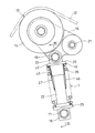
- FIG. 1 Front view showing an example of a belt transmission incorporating the hydraulic auto tensioner according to the first embodiment of the present invention
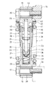
- FIG. 1 Sectional view along line III-III in FIG. 2
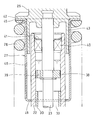
- FIG. 2 An enlarged cross-sectional view near the dust cap of FIG.
- FIG. 1 shows an example of a belt transmission incorporating the hydraulic auto-tensioner 1 according to the first embodiment of the present invention.
- This belt transmission is attached to the crank pulley 3 attached to the crankshaft 2 of the engine, the accessory pulley 5 attached to the rotation shaft 4 of the water pump, and the rotation shaft 6 of the ISG (Integrated Starter Generator)
- an auxiliary pulley 11 attached to a rotary shaft 10 of a compressor of an air conditioner, and these pulleys 3, 5, 7, 9, 11 Belt 12 and a tension adjusting device 13 for keeping the tension of the belt 12 in an appropriate range.
- the rotating shaft 6 of ISG functions as an input shaft of a generator that generates electric power by the driving force of the crankshaft 2 at the time of steady operation of the engine, and forces the crankshaft 2 in a stopped state at engine startup. It functions as an output shaft of an electric motor (starter) to be rotated.
- the tension adjustment device 13 is disposed at a low position of the belt transmission. That is, the belt 12 travels in an annular path circulating with a difference in height via the pulleys 3, 5, 7, 9, 11 so that the hydraulic auto-tensioner 1 is positioned below the annular path. A tension adjustment device 13 is arranged.
- the tension adjusting device 13 has a tension pulley 14 in contact with the belt 12, a pulley arm 15 supporting the tension pulley 14, and a pulley arm 15 in a direction to press the tension pulley 14 against the belt 12. And a hydraulic auto-tensioner 1 for biasing.
- the lower connecting piece 16 of the hydraulic auto-tensioner 1 is rotatably connected to an engine block 18 (see FIG. 3) via a lower connecting shaft 17.
- An upper connecting piece 19 of the hydraulic auto-tensioner 1 is rotatably connected to a pulley arm 15 via an upper connecting shaft 20.
- the pulley arm 15 is swingably supported around a fulcrum shaft 21 fixed to the engine block 18.
- the hydraulic auto-tensioner 1 has a cylinder 22, a rod 23 vertically movably inserted into the cylinder 22, and a cylinder 22 so as to buffer a downward force applied to the rod 23.
- the hydraulic damper mechanism 24 provided inside, the spring seat 25 fixed to the upper end of the rod 23, the return spring 26 biasing the spring seat 25 upward, and the prevention of the entry of dust etc. into the inside of the cylinder 22 And a dust cap 27.
- the cylinder 22 is formed in the shape of a cylinder whose upper end is open and whose lower end is closed.
- a lower connection piece 16 is integrally provided at the lower end of the cylinder 22.
- the lower connecting piece 16 incorporates a bearing 28 rotatably supporting the lower connecting shaft 17.
- a support flange 29 supporting the lower end of the return spring 26 is integrally provided on the outer periphery of the cylinder 22.
- the cylinder 22 is formed of an aluminum alloy.
- the hydraulic damper mechanism 24 includes a steel sleeve 30 fitted in the cylinder 22, a plunger 31 slidably inserted in the sleeve 30 up and down, and a pressure chamber 32 formed on the lower side of the plunger 31. , A reservoir chamber 33 formed on the upper side of the plunger 31, an oil passage 34 communicating between the pressure chamber 32 and the reservoir chamber 33, and a flow of hydraulic oil from the oil chamber 34 side to the pressure chamber 32 side. And a leak gap 36 formed between the sliding surfaces of the plunger 31 and the sleeve 30.
- the pressure chamber 32 is filled with hydraulic oil, and the reservoir chamber 33 contains air and hydraulic oil in upper and lower two layers.
- the oil passage 34 is formed to penetrate the inside of the plunger 31 up and down.
- the check valve 35 is disposed at an end of the oil passage 34 on the pressure chamber 32 side.
- the size of the leak gap 36 is minute, and the difference in radius between the cylindrical surface of the outer periphery of the plunger 31 and the cylindrical surface of the inner periphery of the sleeve 30 is set in the range of 0.015 to 0.080 mm.
- the plunger 31 is biased upward by a plunger spring 37 incorporated in the pressure chamber 32.
- the plunger 31 supports the lower end of the rod 23. When the rod 23 moves up and down, the plunger 31 moves up and down integrally with the rod 23.
- a wear ring 38 is attached to the outer periphery of the insertion portion of the rod 23 into the cylinder 22.
- the wear ring 38 is guided on the inner periphery of the cylinder 22 so that the position of the rod 23 does not deviate from the center of the cylinder 22.
- the wear ring 38 is provided with a through hole 39 through which hydraulic oil passes.
- An annular oil seal 40 slidably fitted on the outer periphery of the rod 23 is fitted on the inner periphery of the upper end opening of the cylinder 22, and the hydraulic oil in the cylinder 22 is sealed by the oil seal 40.
- the oil seal 40 is fixed to the cylinder 22 by a snap ring 41 mounted on the inner periphery of the upper end opening of the cylinder 22.
- the spring seat 25 has an upper connecting piece 19 and a spring receiving flange 42 formed on the outer periphery of the lower end of the upper connecting piece 19, and the upper end of the return spring 26 is received by the spring receiving flange 42. Further, a cylindrical skirt portion 43 extending downward through between the outer periphery of the cylinder 22 and the inner periphery of the return spring 26 is integrally formed on the spring seat 25.
- the upper connecting piece 19 and the spring receiving flange 42 are integrally formed in a seamless manner.
- a bearing 44 rotatably supporting the upper connecting shaft 20 is incorporated in the upper connecting piece 19.
- the return spring 26 is a cylindrical coiled spring having an inner diameter larger than the outer diameter of the cylinder 22, and is disposed coaxially with the cylinder 22 so as to surround the outer periphery of the cylinder 22.
- the dust cap 27 has an annular flange portion 45 sandwiched between the upper end of the return spring 26 and the spring seat 25, and the outer periphery of the cylinder 22 and the return spring 26 from the radial inner end of the flange portion 45. And a cylindrical portion 46 extending downward through an annular gap between the inner and outer circumferences of the two.
- the flange portion 45 is a portion of a flat annular plate sandwiched between the lower surface of the spring receiving flange 42 of the spring seat 25 and the upper end of the return spring 26.
- the cylindrical portion 46 includes a straight portion 47 having a constant outer diameter along the vertical direction, and a tapered portion 48 whose outer diameter gradually decreases from the lower end of the straight portion 47 downward.
- the length of the cylindrical portion 46 in the vertical direction is set to 40% or more and 60% or less of the length of the return spring 26 in the natural state where no external force is applied.
- the length of the tapered portion 48 in the vertical direction is set to 20% or more and 35% or less of the length of the return spring 26 in the natural state where no external force is applied.
- a radially inward annular projection 49 is formed on the lower end of the cylindrical portion 46 (here, the lower end of the tapered portion 48) and fitted on the outer periphery of the cylinder 22 with a gap.
- the size of the annular gap formed between the inner periphery of the tip of the annular projection 49 and the outer periphery of the cylinder 22 is 1.0 mm or less (preferably 0.5 mm or less) in radius.
- the flange portion 45, the cylindrical portion 46, and the annular projection 49 are integrally formed without joint by deep drawing of a metal plate (steel plate, aluminum plate or the like).
- the flange portion 45, the cylindrical portion 46 and the annular protrusion 49 can also be formed of a fiber reinforced resin material in which a fiber reinforcing material such as glass fiber or carbon fiber is combined with a resin material. In this way, the weight of the hydraulic auto-tensioner 1 can be reduced.
- the hydraulic auto-tensioner 1 of this embodiment is provided with a dust cap 27 which covers the upper outer periphery of the cylinder 22 in order to make it difficult to reduce the damper force even when used in an environment with a lot of dust etc. .
- dust and the like outside the hydraulic auto-tensioner 1 move from the lower side to the upper side against the gravity in the vertically elongated space formed between the outer periphery of the cylinder 22 and the cylindrical portion 46 of the dust cap 27. If it does not pass through, it can not reach the opening at the upper end of the cylinder 22. Therefore, even when used in an environment with a large amount of dust etc., it is difficult for dust etc. to penetrate inside the cylinder 22 of the hydraulic autotensioner 1, and the damper force Less likely to occur.
- the hydraulic auto-tensioner 1 sets the length in the vertical direction of the cylindrical portion 46 to 40% or more of the length of the return spring 26 in the natural state where no external force is applied, the cylinder 22
- the length of the vertically elongated space formed between the outer periphery of the dust cap 27 and the cylindrical portion 46 of the dust cap 27 is sufficiently long, and it is possible to effectively prevent the intrusion of dust and the like into the inside of the cylinder 22 ing.
- the hydraulic auto-tensioner 1 is subjected to buckling deformation (the axial center portion of the return spring 26 is in a direction perpendicular to the axis) when the return spring 26 is compressed. Even if the return spring 26 is deformed to curve as a whole, the cylindrical portion 46 of the dust cap 27 has a tapered portion 48 whose diameter gradually decreases downward, so the cylindrical portion 46 of the dust cap 27 It is possible to prevent interference with the return spring 26.
- the radially inward annular projection 49 is formed at the lower end of the cylindrical portion 46, the clearance between the inner periphery of the lower end of the cylindrical portion 46 and the outer periphery of the cylinder 22 is It is difficult for dust and the like to pass through, and dust and the like outside the hydraulic auto-tensioner 1 can be effectively prevented from entering the inside of the cylinder 22.
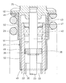
- FIG. 5 shows a second embodiment of the present invention.
- the second embodiment is different from the first embodiment only in the shape of the dust cap 27 and the other configuration is the same. Therefore, the parts corresponding to the first embodiment are given the same reference numerals and the description thereof is omitted.
- the cylindrical portion 46 of the dust cap 27 has a straight shape whose outer diameter is constant over the entire length.
- the length of the cylindrical portion 46 in the vertical direction is set to 40% or more and 60% or less of the length of the return spring 26 in the natural state where no external force is applied.
- a radially inward annular projection 49 is formed at the lower end of the cylindrical portion 46 and fitted on the outer periphery of the cylinder 22 with a gap.
- the size of the annular gap formed between the inner periphery of the tip of the annular projection 49 and the outer periphery of the cylinder 22 is 1.0 mm or less (preferably 0.5 mm or less) in radius.
- FIG. 6 shows a third embodiment of the present invention.
- the third embodiment differs from the first embodiment only in the shape of the dust cap 27 and the other configuration is the same. Therefore, the parts corresponding to the first embodiment are given the same reference numerals and the description thereof is omitted.
- the cylindrical portion 46 includes a straight portion 50 having a constant outer diameter along the vertical direction, and a small diameter straight portion 52 connected to the lower end of the straight portion 50 via the step 51 and having a smaller outer diameter than the straight portion 50.
- a small diameter straight portion 52 has a constant outer diameter along the top and bottom, but the outer diameter of the small diameter straight portion 52 is smaller than the outer diameter of the straight portion 50.
- the length of the cylindrical portion 46 in the vertical direction is set to 40% or more and 60% or less of the length of the return spring 26 in the natural state where no external force is applied.
- the length of the small diameter straight portion 52 in the vertical direction is set to 20% or more and 35% or less of the length of the return spring 26 in the natural state where no external force is applied.
- a radially inward annular projection 49 is formed on the lower end of the cylindrical portion 46 (here, the lower end of the small diameter straight portion 52) to be fitted on the outer periphery of the cylinder 22 with a gap.
- the size of the annular gap formed between the inner periphery of the tip of the annular projection 49 and the outer periphery of the cylinder 22 is 1.0 mm or less (preferably 0.5 mm or less) in radius.
- the cylindrical portion 46 of the dust cap 27 has a shape in which the small diameter straight portion 52 is connected to the lower end of the straight portion 50 via the step portion 51 Therefore, it is possible to prevent the cylindrical portion 46 of the dust cap 27 from interfering with the return spring 26.
Landscapes
- Engineering & Computer Science (AREA)
- General Engineering & Computer Science (AREA)
- Mechanical Engineering (AREA)
- Devices For Conveying Motion By Means Of Endless Flexible Members (AREA)
Abstract
上端が開口し、下端が閉塞したシリンダ(22)と、シリンダ(22)に上下に移動可能に挿入されたロッド(23)と、シリンダ(22)の内部に設けられた油圧ダンパ機構(24)と、ロッド(23)の上端に固定されたばね座(25)と、シリンダ(22)の外周を囲むように配置されたリターンスプリング(26)と、を備える油圧式オートテンショナにおいて、リターンスプリング(26)の上端とばね座(25)の間に挟み込まれる環状のフランジ部(45)と、フランジ部(45)の径方向内端からシリンダ(22)の外周とリターンスプリング(26)の内周との間の環状隙間を通って下方に延びる筒部(46)とからなるダストキャップ(27)を設ける。
Description
この発明は、作動油を用いてダンパ力を発生する油圧式オートテンショナに関する。
自動車の補機、たとえばオルタネータやカーエアコンやウォータポンプなどは、その回転軸がエンジンのクランクシャフトに補機ベルトで連結され、その補機ベルトを介して駆動される。この補機ベルトの張力を適正範囲に保つために、一般に、支点軸を中心として揺動可能に設けたプーリアームと、そのプーリアームに回転可能に取り付けたテンションプーリと、そのテンションプーリを補機ベルトに押さえ付ける方向にプーリアームを付勢するオートテンショナとからなる張力調整装置が使用される。
この張力調整装置に組み込まれる油圧式オートテンショナとして、例えば、特許文献1に記載のものが知られている。この油圧式オートテンショナは、上端が開口し、下端が閉塞したシリンダと、そのシリンダに上下に移動可能に挿入されたロッドと、そのロッドの上端に固定されたばね座と、そのばね座を上方に付勢するリターンスプリングとを有し、補機ベルトの張力が変動すると、その補機ベルトの張力とリターンスプリングの付勢力がつりあう位置までロッドが移動して補機ベルトの張力変動を吸収する。またこの油圧式オートテンショナは、補機ベルトの振動を減衰するため、補機ベルトからロッドに負荷される下向きの力を緩衝する油圧ダンパ機構をシリンダの内部に有する。
ところで、上記のような油圧式オートテンショナは、補機ベルトのレイアウトの都合上、ベルト伝動装置の低い位置に配置されることがある。この場合、ベルト伝動装置で発生する粉塵等が、油圧式オートテンショナの周囲に降り掛かるため、油圧式オートテンショナのシリンダ内部に粉塵等が侵入する問題が生じやすくなり、シリンダ内部に侵入した粉塵等によって、油圧ダンパ機構の構成部品の摩耗が促進され、その結果、油圧式オートテンショナのダンパ力が低下するおそれがあることが分かった。
この発明が解決しようとする課題は、粉塵等の多い環境で使用したときにもダンパ力の低下が生じにくい油圧式オートテンショナを提供することである。
上記課題を解決するため、この発明では、以下の構成の油圧式オートテンショナを提供する。
上端が開口し、下端が閉塞したシリンダと、
前記シリンダに上下に移動可能に挿入されたロッドと、
前記ロッドに負荷される下向きの力を緩衝するように前記シリンダの内部に設けられた油圧ダンパ機構と、
前記ロッドの上端に固定されたばね座と、
前記シリンダの外周を囲むように配置され、前記ばね座を上方に付勢するリターンスプリングと、を備える油圧式オートテンショナにおいて、
前記リターンスプリングの上端と前記ばね座の間に挟み込まれる環状のフランジ部と、前記フランジ部の径方向内端から前記シリンダの外周と前記リターンスプリングの内周との間の環状隙間を通って下方に延びる筒部とからなるダストキャップを設けたことを特徴とする油圧式オートテンショナ。
上端が開口し、下端が閉塞したシリンダと、
前記シリンダに上下に移動可能に挿入されたロッドと、
前記ロッドに負荷される下向きの力を緩衝するように前記シリンダの内部に設けられた油圧ダンパ機構と、
前記ロッドの上端に固定されたばね座と、
前記シリンダの外周を囲むように配置され、前記ばね座を上方に付勢するリターンスプリングと、を備える油圧式オートテンショナにおいて、
前記リターンスプリングの上端と前記ばね座の間に挟み込まれる環状のフランジ部と、前記フランジ部の径方向内端から前記シリンダの外周と前記リターンスプリングの内周との間の環状隙間を通って下方に延びる筒部とからなるダストキャップを設けたことを特徴とする油圧式オートテンショナ。
このようにすると、油圧式オートテンショナの外部の粉塵等は、シリンダの外周とダストキャップの筒部との間に形成される上下に細長い空間を、重力に逆らって下側から上側に通過しない限り、シリンダの上端の開口に到達することができないので、粉塵等の多い環境で使用したときにも、油圧式オートテンショナのシリンダ内部に粉塵等が侵入しにくく、ダンパ力の低下が生じにくい。
前記筒部の上下方向の長さを、外力が作用していない自然状態での前記リターンスプリングの長さの40%以上に設定すると好ましい。
このようにすると、シリンダの外周とダストキャップの筒部との間に形成される上下に細長い空間の長さが十分に長くなり、シリンダ内部への粉塵等の侵入を効果的に防止することができる。
前記筒部は、上下方向に沿って外径が一定のストレート部と、前記ストレート部の下端から下方に向かって外径が次第に縮径するテーパ部とを有し、前記テーパ部の上下方向の長さが、外力が作用していない自然状態での前記リターンスプリングの長さの20%以上に設定されているものを採用すると好ましい。
このようにすると、補機ベルトの張力が大きくなってリターンスプリングが圧縮されたときに、リターンスプリングに座屈変形(リターンスプリングの軸方向の中央部分が軸直角方向にずれるようにリターンスプリングが全体として湾曲する変形)が生じても、ダストキャップの筒部が下方に向かって次第に縮径するテーパ部をもつ形状なので、ダストキャップの筒部がリターンスプリングに干渉するのを防止することができる。
また、前記筒部は、上下方向に沿って外径が一定のストレート部と、前記ストレート部の下端に段差部を介して接続され、前記ストレート部よりも外径が小さい小径ストレート部とを有し、前記小径ストレート部の上下方向の長さが、外力が作用していない自然状態での前記リターンスプリングの長さの20%以上に設定されているものを採用することもできる。
このようにすると、補機ベルトの張力が大きくなってリターンスプリングが圧縮されたときに、リターンスプリングに座屈変形(リターンスプリングの軸方向の中央部分が軸直角方向にずれるようにリターンスプリングが全体として湾曲する変形)が生じても、ダストキャップの筒部が、ストレート部の下端に段差部を介して小径ストレート部を接続した形状なので、ダストキャップの筒部がリターンスプリングに干渉するのを防止することができる。
前記筒部の下端に、前記シリンダの外周に隙間をもって嵌合する径方向内向きの環状突起を形成すると好ましい。
このようにすると、筒部の下端に径方向内向きの環状突起が形成されているので、筒部の下端の内周とシリンダの外周との間の隙間を粉塵等が通過しにくくなり、油圧式オートテンショナの外部の粉塵等がシリンダ内部に侵入するのを効果的に防止することが可能となる。
この発明の油圧式オートテンショナは、粉塵等の多い環境で使用したときにも、油圧式オートテンショナのシリンダ内部に粉塵等が侵入しにくく、ダンパ力の低下が生じにくい。
図1に、この発明の第1実施形態の油圧式オートテンショナ1を組み込んだベルト伝動装置の例を示す。このベルト伝動装置は、エンジンのクランクシャフト2に取り付けられたクランクプーリ3と、ウォータポンプの回転軸4に取り付けられた補機プーリ5と、ISG(Integrated Starter Generator)の回転軸6に取り付けられたISGプーリ7と、固定軸8に取り付けられたアイドラプーリ9と、エアコンのコンプレッサの回転軸10に取り付けられた補機プーリ11と、これらの各プーリ3,5,7,9,11に掛け渡されたベルト12と、ベルト12の張力を適正範囲に保つ張力調整装置13とを有する。
ISGの回転軸6は、エンジンの定常運転時には、クランクシャフト2の駆動力によって発電を行なう発電機(ジェネレータ)の入力軸として機能し、エンジン始動時には、停止状態にあるクランクシャフト2を強制的に回転させる電動モータ(スタータ)の出力軸として機能する。
張力調整装置13は、ベルト伝動装置の低い位置に配置されている。すなわち、ベルト12は、各プーリプーリ3,5,7,9,11を経由しながら高低差をもって循環する環状経路を走行し、その環状経路の下側に油圧式オートテンショナ1が位置するように、張力調整装置13が配置されている。
図2、図3に示すように、張力調整装置13は、ベルト12に接触するテンションプーリ14と、テンションプーリ14を支持するプーリアーム15と、テンションプーリ14をベルト12に押さえ付ける方向にプーリアーム15を付勢する油圧式オートテンショナ1とを有する。
油圧式オートテンショナ1の下部連結片16は下部連結軸17を介してエンジンブロック18(図3参照)に回動可能に連結されている。油圧式オートテンショナ1の上部連結片19は上部連結軸20を介してプーリアーム15に回動可能に連結されている。プーリアーム15は、エンジンブロック18に固定された支点軸21を中心に揺動可能に支持されている。
図3に示すように、油圧式オートテンショナ1は、シリンダ22と、シリンダ22に上下に移動可能に挿入されたロッド23と、ロッド23に負荷される下向きの力を緩衝するようにシリンダ22の内部に設けられた油圧ダンパ機構24と、ロッド23の上端に固定されたばね座25と、ばね座25を上方に付勢するリターンスプリング26と、シリンダ22の内部への粉塵等の侵入を防止するダストキャップ27とを有する。
シリンダ22は、上端が開口し、下端が閉塞した筒状に形成されている。シリンダ22の下端には、下部連結片16が一体に設けられている。下部連結片16には、下部連結軸17を回動可能に支持する軸受28が組み込まれている。シリンダ22の外周には、リターンスプリング26の下端を支持する支持フランジ29が一体に設けられている。シリンダ22は、アルミ合金で形成されている。
油圧ダンパ機構24は、シリンダ22内に嵌め込まれた鋼製のスリーブ30と、スリーブ30内に上下に摺動可能に挿入されたプランジャ31と、プランジャ31の下側に形成された圧力室32と、プランジャ31の上側に形成されたリザーバ室33と、圧力室32とリザーバ室33の間を連通する油通路34と、油通路34のリザーバ室33側から圧力室32側への作動油の流れのみを許容するチェックバルブ35と、プランジャ31とスリーブ30の摺動面間に形成されたリーク隙間36とからなる。
圧力室32は、作動油で満たされ、リザーバ室33には、空気と作動油が上下二層に収容されている。油通路34は、プランジャ31の内部を上下に貫通して形成されている。チェックバルブ35は、油通路34の圧力室32側の端部に配置されている。リーク隙間36の大きさは微小であり、プランジャ31の外周の円筒面とスリーブ30の内周の円筒面の半径差で0.015~0.080mmの範囲に設定されている。プランジャ31は、圧力室32に組み込まれたプランジャスプリング37で上方に付勢されている。プランジャ31はロッド23の下端を支持しており、ロッド23が上下に移動するとき、そのロッド23と一体にプランジャ31が上下に移動するようになっている。
ロッド23のシリンダ22内への挿入部分の外周には、ウェアリング38が取り付けられている。ウェアリング38は、ロッド23の位置がシリンダ22の中心からずれないようにシリンダ22の内周で案内されている。ウェアリング38には、作動油を通過させる貫通孔39が設けられている。
シリンダ22の上端開口の内周には、ロッド23の外周に摺接する環状のオイルシール40が嵌め込まれ、このオイルシール40によってシリンダ22内の作動油が密封されている。オイルシール40は、シリンダ22の上端開口の内周に装着した止め輪41でシリンダ22に固定されている。
ばね座25は、上部連結片19と、上部連結片19の下端外周に形成されたばね受けフランジ42とを有し、そのばね受けフランジ42でリターンスプリング26の上端を受けている。また、ばね座25には、シリンダ22の外周とリターンスプリング26の内周との間を通って下方に延びる筒状のスカート部43が一体に形成されている。上部連結片19とばね受けフランジ42は、継ぎ目のない一体に形成されている。上部連結片19には、上部連結軸20を回動可能に支持する軸受44が組み込まれている。
リターンスプリング26は、シリンダ22の外径よりも大きい内径をもつ円筒コイルばねであり、シリンダ22の外周を囲むようにシリンダ22と同軸に配置されている。
図4に示すように、ダストキャップ27は、リターンスプリング26の上端とばね座25の間に挟み込まれる環状のフランジ部45と、フランジ部45の径方向内端からシリンダ22の外周とリターンスプリング26の内周との間の環状隙間を通って下方に延びる筒部46とからなる。フランジ部45は、ばね座25のばね受けフランジ42の下面と、リターンスプリング26の上端との間に挟み込まれる平坦な環状板の部分である。
筒部46は、上下方向に沿って外径が一定のストレート部47と、ストレート部47の下端から下方に向かって外径が次第に縮径するテーパ部48とからなる。筒部46の上下方向の長さは、外力が作用していない自然状態でのリターンスプリング26の長さの40%以上60%以下に設定されている。テーパ部48の上下方向の長さは、外力が作用していない自然状態でのリターンスプリング26の長さの20%以上35%以下に設定されている。筒部46の上下方向の長さを外力が作用していない自然状態でのリターンスプリング26の長さの60%以下に設定することにより、ベルト12の張力が急激に大きくなり、ばね座25とダストキャップ27が下方に大きく移動したときにも、ダストキャップ27の筒部46の下端がシリンダ22の下部に干渉するのを防止することができる。
筒部46の下端(ここではテーパ部48の下端)には、シリンダ22の外周に隙間をもって嵌合する径方向内向きの環状突起49が形成されている。環状突起49の先端部の内周とシリンダ22の外周との間に形成される環状隙間の大きさは、半径で1.0mm以下(好ましくは0.5mm以下)とされている。フランジ部45と筒部46と環状突起49は、金属板(鋼板、アルミ板など)の深絞り加工によって継ぎ目のない一体に形成されている。フランジ部45と筒部46と環状突起49は、ガラス繊維や炭素繊維などの繊維強化材を樹脂材料に複合した繊維強化樹脂材料で形成することも可能である。このようにすると、油圧式オートテンショナ1の軽量化を図ることができる。
次に、この油圧式オートテンショナ1の動作例を説明する。
図2に示すベルト12の張力が小さくなると、リターンスプリング26の付勢力によって、図3に示すロッド23がスリーブ30から突出する方向にロッド23が移動し、ベルト12の弛みを吸収する。このとき、図3に示す圧力室32の容積が拡大するので、チェックバルブ35が開き、リザーバ室33内の作動油が油通路34を通って圧力室32に流入する。
一方、図2に示すベルト12の張力が大きくなると、そのベルト12の張力によって、図3に示すロッド23がスリーブ30内に押し込まれる方向にロッド23が移動し、ベルト12の緊張を吸収する。このとき、図3に示す圧力室32の容積が縮小するので、チェックバルブ35が閉じ、圧力室32内の作動油がリーク隙間36を通って流出し、その作動油の粘性抵抗によってダンパ力を生じる。
ところで、上記の油圧式オートテンショナ1は、図1に示すように、ベルト伝動装置の低い位置に配置した場合、ベルト伝動装置で発生する粉塵等が、油圧式オートテンショナ1の周囲に降り掛かるため、油圧式オートテンショナ1のシリンダ22内部に粉塵等が侵入する問題が生じやすくなり、シリンダ22内部に侵入した粉塵等によって、油圧ダンパ機構24の構成部品の摩耗が促進され、その結果、油圧式オートテンショナ1のダンパ力が低下するおそれがある。
これに対し、この実施形態の油圧式オートテンショナ1は、粉塵等の多い環境で使用したときにもダンパ力の低下を生じにくくするため、シリンダ22の上部外周を覆うダストキャップ27を設けている。このようにすると、油圧式オートテンショナ1の外部の粉塵等は、シリンダ22の外周とダストキャップ27の筒部46との間に形成される上下に細長い空間を、重力に逆らって下側から上側に通過しない限り、シリンダ22の上端の開口に到達することができないので、粉塵等の多い環境で使用したときにも、油圧式オートテンショナ1のシリンダ22内部に粉塵等が侵入しにくく、ダンパ力の低下が生じにくい。
また、この油圧式オートテンショナ1は、筒部46の上下方向の長さを、外力が作用していない自然状態でのリターンスプリング26の長さの40%以上に設定しているので、シリンダ22の外周とダストキャップ27の筒部46との間に形成される上下に細長い空間の長さが十分に長くなり、シリンダ22内部への粉塵等の侵入を効果的に防止することが可能となっている。
また、この油圧式オートテンショナ1は、ベルト12の張力が大きくなってリターンスプリング26が圧縮されたときに、リターンスプリング26に座屈変形(リターンスプリング26の軸方向の中央部分が軸直角方向にずれるようにリターンスプリング26が全体として湾曲する変形)が生じても、ダストキャップ27の筒部46が下方に向かって次第に縮径するテーパ部48をもつ形状なので、ダストキャップ27の筒部46がリターンスプリング26に干渉するのを防止することが可能となっている。
また、この油圧式オートテンショナ1は、筒部46の下端に径方向内向きの環状突起49が形成されているので、筒部46の下端の内周とシリンダ22の外周との間の隙間を粉塵等が通過しにくく、油圧式オートテンショナ1の外部の粉塵等がシリンダ22内部に侵入するのを効果的に防止することが可能となっている。
図5に、この発明の第2実施形態を示す。第2実施形態は、第1実施形態とダストキャップ27の形状が異なるだけであり、その他の構成は同一である。そのため、第1実施形態に対応する部分には同一の符号を付して説明を省略する。
ダストキャップ27の筒部46は、全長にわたって外径が一定のストレート形状である。筒部46の上下方向の長さは、外力が作用していない自然状態でのリターンスプリング26の長さの40%以上60%以下に設定されている。筒部46の下端には、シリンダ22の外周に隙間をもって嵌合する径方向内向きの環状突起49が形成されている。環状突起49の先端部の内周とシリンダ22の外周との間に形成される環状隙間の大きさは、半径で1.0mm以下(好ましくは0.5mm以下)とされている。
図6に、この発明の第3実施形態を示す。第3実施形態は、第1実施形態とダストキャップ27の形状が異なるだけであり、その他の構成は同一である。そのため、第1実施形態に対応する部分には同一の符号を付して説明を省略する。
筒部46は、上下方向に沿って外径が一定のストレート部50と、ストレート部50の下端に段差部51を介して接続され、ストレート部50よりも外径が小さい小径ストレート部52とを有する。小径ストレート部52も、ストレート部50と同様に、上下に沿って外径が一定であるが、小径ストレート部52の外径は、ストレート部50の外径よりも小さい。
筒部46の上下方向の長さは、外力が作用していない自然状態でのリターンスプリング26の長さの40%以上60%以下に設定されている。小径ストレート部52の上下方向の長さは、外力が作用していない自然状態でのリターンスプリング26の長さの20%以上35%以下に設定されている。
筒部46の下端(ここでは小径ストレート部52の下端)には、シリンダ22の外周に隙間をもって嵌合する径方向内向きの環状突起49が形成されている。環状突起49の先端部の内周とシリンダ22の外周との間に形成される環状隙間の大きさは、半径で1.0mm以下(好ましくは0.5mm以下)とされている。
この第3実施形態の油圧式オートテンショナ1は、ベルト12の張力が大きくなってリターンスプリング26が圧縮されたときに、リターンスプリング26に座屈変形(リターンスプリング26の軸方向の中央部分が軸直角方向にずれるようにリターンスプリング26が全体として湾曲する変形)が生じても、ダストキャップ27の筒部46が、ストレート部50の下端に段差部51を介して小径ストレート部52を接続した形状なので、ダストキャップ27の筒部46がリターンスプリング26に干渉するのを防止することが可能となっている。
今回開示された実施の形態はすべての点で例示であって制限的なものではないと考えられるべきである。本発明の範囲は上記した説明ではなくて特許請求の範囲によって示され、特許請求の範囲と均等の意味および範囲内でのすべての変更が含まれることが意図される。
1 油圧式オートテンショナ
22 シリンダ
23 ロッド
24 油圧ダンパ機構
25 ばね座
26 リターンスプリング
27 ダストキャップ
45 フランジ部
46 筒部
47 ストレート部
48 テーパ部
49 環状突起
50 ストレート部
51 段差部
52 小径ストレート部
22 シリンダ
23 ロッド
24 油圧ダンパ機構
25 ばね座
26 リターンスプリング
27 ダストキャップ
45 フランジ部
46 筒部
47 ストレート部
48 テーパ部
49 環状突起
50 ストレート部
51 段差部
52 小径ストレート部
Claims (5)
- 上端が開口し、下端が閉塞したシリンダ(22)と、
前記シリンダ(22)に上下に移動可能に挿入されたロッド(23)と、
前記ロッド(23)に負荷される下向きの力を緩衝するように前記シリンダ(22)の内部に設けられた油圧ダンパ機構(24)と、
前記ロッド(23)の上端に固定されたばね座(25)と、
前記シリンダ(22)の外周を囲むように配置され、前記ばね座(25)を上方に付勢するリターンスプリング(26)と、を備える油圧式オートテンショナにおいて、
前記リターンスプリング(26)の上端と前記ばね座(25)の間に挟み込まれる環状のフランジ部(45)と、前記フランジ部(45)の径方向内端から前記シリンダ(22)の外周と前記リターンスプリング(26)の内周との間の環状隙間を通って下方に延びる筒部(46)とからなるダストキャップ(27)を設けたことを特徴とする油圧式オートテンショナ。 - 前記筒部(46)の上下方向の長さを、外力が作用していない自然状態での前記リターンスプリング(26)の長さの40%以上に設定した請求項1に記載の油圧式オートテンショナ。
- 前記筒部(46)は、上下方向に沿って外径が一定のストレート部(47)と、前記ストレート部(47)の下端から下方に向かって外径が次第に縮径するテーパ部(48)とを有し、前記テーパ部(48)の上下方向の長さが、外力が作用していない自然状態での前記リターンスプリング(26)の長さの20%以上に設定されている請求項1または2に記載の油圧式オートテンショナ。
- 前記筒部(46)は、上下方向に沿って外径が一定のストレート部(50)と、前記ストレート部(50)の下端に段差部(51)を介して接続され、前記ストレート部(50)よりも外径が小さい小径ストレート部(52)とを有し、前記小径ストレート部(52)の上下方向の長さが、外力が作用していない自然状態での前記リターンスプリング(26)の長さの20%以上に設定されている請求項1または2に記載の油圧式オートテンショナ。
- 前記筒部(46)の下端に、前記シリンダ(22)の外周に隙間をもって嵌合する径方向内向きの環状突起(49)が形成されている請求項1から4のいずれかに記載の油圧式オートテンショナ。
Applications Claiming Priority (2)
| Application Number | Priority Date | Filing Date | Title |
|---|---|---|---|
| JP2017-182291 | 2017-09-22 | ||
| JP2017182291A JP6800823B2 (ja) | 2017-09-22 | 2017-09-22 | 油圧式オートテンショナ |
Publications (1)
| Publication Number | Publication Date |
|---|---|
| WO2019059336A1 true WO2019059336A1 (ja) | 2019-03-28 |
Family
ID=65810328
Family Applications (1)
| Application Number | Title | Priority Date | Filing Date |
|---|---|---|---|
| PCT/JP2018/034992 Ceased WO2019059336A1 (ja) | 2017-09-22 | 2018-09-21 | 油圧式オートテンショナ |
Country Status (2)
| Country | Link |
|---|---|
| JP (1) | JP6800823B2 (ja) |
| WO (1) | WO2019059336A1 (ja) |
Cited By (1)
| Publication number | Priority date | Publication date | Assignee | Title |
|---|---|---|---|---|
| CN112722700A (zh) * | 2020-12-31 | 2021-04-30 | 江苏帝全自动化机械有限公司 | 一种具有防跳带结构的高速开箱机 |
Citations (2)
| Publication number | Priority date | Publication date | Assignee | Title |
|---|---|---|---|---|
| JP2005042774A (ja) * | 2003-07-24 | 2005-02-17 | Ntn Corp | 油圧式オートテンショナ |
| JP2007218401A (ja) * | 2006-02-20 | 2007-08-30 | Ntn Corp | 油圧式オートテンショナ |
-
2017
- 2017-09-22 JP JP2017182291A patent/JP6800823B2/ja active Active
-
2018
- 2018-09-21 WO PCT/JP2018/034992 patent/WO2019059336A1/ja not_active Ceased
Patent Citations (2)
| Publication number | Priority date | Publication date | Assignee | Title |
|---|---|---|---|---|
| JP2005042774A (ja) * | 2003-07-24 | 2005-02-17 | Ntn Corp | 油圧式オートテンショナ |
| JP2007218401A (ja) * | 2006-02-20 | 2007-08-30 | Ntn Corp | 油圧式オートテンショナ |
Cited By (2)
| Publication number | Priority date | Publication date | Assignee | Title |
|---|---|---|---|---|
| CN112722700A (zh) * | 2020-12-31 | 2021-04-30 | 江苏帝全自动化机械有限公司 | 一种具有防跳带结构的高速开箱机 |
| CN112722700B (zh) * | 2020-12-31 | 2024-10-29 | 江苏帝全自动化机械有限公司 | 一种具有防跳带结构的高速开箱机 |
Also Published As
| Publication number | Publication date |
|---|---|
| JP6800823B2 (ja) | 2020-12-16 |
| JP2019056452A (ja) | 2019-04-11 |
Similar Documents
| Publication | Publication Date | Title |
|---|---|---|
| WO2012144402A1 (ja) | 油圧式オートテンショナ | |
| WO2016143788A1 (ja) | 油圧式オートテンショナ | |
| JP2013204767A (ja) | 油圧式オートテンショナ | |
| WO2019059336A1 (ja) | 油圧式オートテンショナ | |
| WO2015019838A1 (ja) | 油圧式オートテンショナ | |
| EP2184511A1 (en) | Hydraulic auto-tensioner and belt transmission device | |
| JP6560939B2 (ja) | 油圧式オートテンショナ | |
| JP6250343B2 (ja) | 油圧式オートテンショナ | |
| JP4718355B2 (ja) | 油圧式オートテンショナ | |
| JP6069556B2 (ja) | 油圧式オートテンショナ | |
| WO2018168745A1 (ja) | 油圧式オートテンショナ | |
| JP6644504B2 (ja) | 油圧式オートテンショナ | |
| EP3557095B1 (en) | Support structure for tensioner device | |
| JP2012225447A (ja) | オートテンショナ | |
| JP6659454B2 (ja) | オートテンショナ | |
| JP6599165B2 (ja) | 油圧式オートテンショナ | |
| JP6581451B2 (ja) | 油圧式オートテンショナ | |
| JP4718346B2 (ja) | 油圧式オートテンショナ | |
| JP5282994B2 (ja) | オートテンショナ | |
| JP6234252B2 (ja) | 油圧式オートテンショナ | |
| JP2010223290A (ja) | 油圧式オートテンショナ | |
| JP2006207614A (ja) | ベルトの張力調整装置 | |
| JP2008175224A (ja) | オートテンショナ | |
| JP2007303646A (ja) | 油圧式オートテンショナ | |
| JP2008175272A (ja) | 油圧式オートテンショナ |
Legal Events
| Date | Code | Title | Description |
|---|---|---|---|
| 121 | Ep: the epo has been informed by wipo that ep was designated in this application |
Ref document number: 18859755 Country of ref document: EP Kind code of ref document: A1 |
|
| NENP | Non-entry into the national phase |
Ref country code: DE |
|
| 122 | Ep: pct application non-entry in european phase |
Ref document number: 18859755 Country of ref document: EP Kind code of ref document: A1 |