WO2019059152A1 - 電流制御装置 - Google Patents
電流制御装置 Download PDFInfo
- Publication number
- WO2019059152A1 WO2019059152A1 PCT/JP2018/034378 JP2018034378W WO2019059152A1 WO 2019059152 A1 WO2019059152 A1 WO 2019059152A1 JP 2018034378 W JP2018034378 W JP 2018034378W WO 2019059152 A1 WO2019059152 A1 WO 2019059152A1
- Authority
- WO
- WIPO (PCT)
- Prior art keywords
- current
- full
- control
- cycle
- target
- Prior art date
- Legal status (The legal status is an assumption and is not a legal conclusion. Google has not performed a legal analysis and makes no representation as to the accuracy of the status listed.)
- Ceased
Links
Images





Classifications
-
- F—MECHANICAL ENGINEERING; LIGHTING; HEATING; WEAPONS; BLASTING
- F16—ENGINEERING ELEMENTS AND UNITS; GENERAL MEASURES FOR PRODUCING AND MAINTAINING EFFECTIVE FUNCTIONING OF MACHINES OR INSTALLATIONS; THERMAL INSULATION IN GENERAL
- F16H—GEARING
- F16H61/00—Control functions within control units of change-speed- or reversing-gearings for conveying rotary motion ; Control of exclusively fluid gearing, friction gearing, gearings with endless flexible members or other particular types of gearing
- F16H61/02—Control functions within control units of change-speed- or reversing-gearings for conveying rotary motion ; Control of exclusively fluid gearing, friction gearing, gearings with endless flexible members or other particular types of gearing characterised by the signals used
- F16H61/0202—Control functions within control units of change-speed- or reversing-gearings for conveying rotary motion ; Control of exclusively fluid gearing, friction gearing, gearings with endless flexible members or other particular types of gearing characterised by the signals used the signals being electric
- F16H61/0251—Elements specially adapted for electric control units, e.g. valves for converting electrical signals to fluid signals
-
- F—MECHANICAL ENGINEERING; LIGHTING; HEATING; WEAPONS; BLASTING
- F16—ENGINEERING ELEMENTS AND UNITS; GENERAL MEASURES FOR PRODUCING AND MAINTAINING EFFECTIVE FUNCTIONING OF MACHINES OR INSTALLATIONS; THERMAL INSULATION IN GENERAL
- F16K—VALVES; TAPS; COCKS; ACTUATING-FLOATS; DEVICES FOR VENTING OR AERATING
- F16K31/00—Actuating devices; Operating means; Releasing devices
- F16K31/02—Actuating devices; Operating means; Releasing devices electric; magnetic
- F16K31/06—Actuating devices; Operating means; Releasing devices electric; magnetic using a magnet, e.g. diaphragm valves, cutting off by means of a liquid
-
- G—PHYSICS
- G01—MEASURING; TESTING
- G01R—MEASURING ELECTRIC VARIABLES; MEASURING MAGNETIC VARIABLES
- G01R19/00—Arrangements for measuring currents or voltages or for indicating presence or sign thereof
- G01R19/0007—Frequency selective voltage or current level measuring
-
- H—ELECTRICITY
- H01—ELECTRIC ELEMENTS
- H01F—MAGNETS; INDUCTANCES; TRANSFORMERS; SELECTION OF MATERIALS FOR THEIR MAGNETIC PROPERTIES
- H01F7/00—Magnets
- H01F7/06—Electromagnets; Actuators including electromagnets
- H01F7/08—Electromagnets; Actuators including electromagnets with armatures
- H01F7/18—Circuit arrangements for obtaining desired operating characteristics, e.g. for slow operation, for sequential energisation of windings, for high-speed energisation of windings
-
- H—ELECTRICITY
- H02—GENERATION; CONVERSION OR DISTRIBUTION OF ELECTRIC POWER
- H02H—EMERGENCY PROTECTIVE CIRCUIT ARRANGEMENTS
- H02H3/00—Emergency protective circuit arrangements for automatic disconnection directly responsive to an undesired change from normal electric working condition with or without subsequent reconnection ; integrated protection
- H02H3/08—Emergency protective circuit arrangements for automatic disconnection directly responsive to an undesired change from normal electric working condition with or without subsequent reconnection ; integrated protection responsive to excess current
-
- H—ELECTRICITY
- H02—GENERATION; CONVERSION OR DISTRIBUTION OF ELECTRIC POWER
- H02H—EMERGENCY PROTECTIVE CIRCUIT ARRANGEMENTS
- H02H3/00—Emergency protective circuit arrangements for automatic disconnection directly responsive to an undesired change from normal electric working condition with or without subsequent reconnection ; integrated protection
- H02H3/26—Emergency protective circuit arrangements for automatic disconnection directly responsive to an undesired change from normal electric working condition with or without subsequent reconnection ; integrated protection responsive to difference between voltages or between currents; responsive to phase angle between voltages or between currents
-
- H—ELECTRICITY
- H02—GENERATION; CONVERSION OR DISTRIBUTION OF ELECTRIC POWER
- H02H—EMERGENCY PROTECTIVE CIRCUIT ARRANGEMENTS
- H02H7/00—Emergency protective circuit arrangements specially adapted for specific types of electric machines or apparatus or for sectionalised protection of cable or line systems, and effecting automatic switching in the event of an undesired change from normal working conditions
- H02H7/22—Emergency protective circuit arrangements specially adapted for specific types of electric machines or apparatus or for sectionalised protection of cable or line systems, and effecting automatic switching in the event of an undesired change from normal working conditions for distribution gear, e.g. bus-bar systems; for switching devices
-
- F—MECHANICAL ENGINEERING; LIGHTING; HEATING; WEAPONS; BLASTING
- F16—ENGINEERING ELEMENTS AND UNITS; GENERAL MEASURES FOR PRODUCING AND MAINTAINING EFFECTIVE FUNCTIONING OF MACHINES OR INSTALLATIONS; THERMAL INSULATION IN GENERAL
- F16H—GEARING
- F16H61/00—Control functions within control units of change-speed- or reversing-gearings for conveying rotary motion ; Control of exclusively fluid gearing, friction gearing, gearings with endless flexible members or other particular types of gearing
- F16H61/02—Control functions within control units of change-speed- or reversing-gearings for conveying rotary motion ; Control of exclusively fluid gearing, friction gearing, gearings with endless flexible members or other particular types of gearing characterised by the signals used
- F16H61/0202—Control functions within control units of change-speed- or reversing-gearings for conveying rotary motion ; Control of exclusively fluid gearing, friction gearing, gearings with endless flexible members or other particular types of gearing characterised by the signals used the signals being electric
- F16H61/0251—Elements specially adapted for electric control units, e.g. valves for converting electrical signals to fluid signals
- F16H2061/0255—Solenoid valve using PWM or duty-cycle control
-
- F—MECHANICAL ENGINEERING; LIGHTING; HEATING; WEAPONS; BLASTING
- F16—ENGINEERING ELEMENTS AND UNITS; GENERAL MEASURES FOR PRODUCING AND MAINTAINING EFFECTIVE FUNCTIONING OF MACHINES OR INSTALLATIONS; THERMAL INSULATION IN GENERAL
- F16H—GEARING
- F16H61/00—Control functions within control units of change-speed- or reversing-gearings for conveying rotary motion ; Control of exclusively fluid gearing, friction gearing, gearings with endless flexible members or other particular types of gearing
- F16H61/02—Control functions within control units of change-speed- or reversing-gearings for conveying rotary motion ; Control of exclusively fluid gearing, friction gearing, gearings with endless flexible members or other particular types of gearing characterised by the signals used
- F16H61/0202—Control functions within control units of change-speed- or reversing-gearings for conveying rotary motion ; Control of exclusively fluid gearing, friction gearing, gearings with endless flexible members or other particular types of gearing characterised by the signals used the signals being electric
- F16H61/0251—Elements specially adapted for electric control units, e.g. valves for converting electrical signals to fluid signals
- F16H2061/026—On-off solenoid valve
Definitions
- the present disclosure relates to a current control device that controls the current of a solenoid of a solenoid valve.
- the current control mode executed by the current control device of Patent Document 1 includes a steady mode and a transient mode.
- the steady mode is performed when the target current is constant.
- on / off of the current that is, energization / non-energization
- Transient mode is performed when the target current is changed.
- the current is fully turned on to the target current, and when the target current is reached, the current is repeatedly turned on and off in a cycle shorter than the PWM cycle of the steady mode, and preparation for resynchronization with the PWM cycle of the steady mode is made.
- the transition to the steady mode is performed.
- Patent Document 1 By the way, it is conceivable to apply the current control technology disclosed in Patent Document 1 to a solenoid valve.
- the target current is turned off. Therefore, when applied to a solenoid valve, there is a concern that the valve body can not reach a desired overstroke state (that is, an appropriate position for achieving high response), and fluctuation delay of the control amount may occur.
- Patent Document 1 when transitioning from the transient mode to the steady mode, there is a standby period in which the current is repeatedly turned on and off at a relatively fast frequency until the PWM cycle of the steady mode is reached. Therefore, when applied to a solenoid valve, the valve body can not follow since the current amplitude during the waiting period is very small, and the dynamic friction state of the valve body is not maintained. This leads to a delay in the operation of the valve body, and there is a concern that the overshoot of the control amount becomes large.
- the present disclosure has been made in view of the above-described point, and an object thereof is to provide a solenoid current control device capable of enhancing the responsiveness of a control amount and suppressing an overshoot of the control amount. .
- the current control device includes a current acquisition unit, a steady control unit, and a target determination unit.
- the current acquisition unit acquires an excitation current of the solenoid.
- the steady state control unit performs steady state control to keep the average value of the excitation current close to the target current by repeating the operation of energizing the solenoid and deenergizing the solenoid at a predetermined on / off cycle.
- the target determination unit determines whether or not the target current is changed at predetermined target determination cycles shorter than the on / off cycle when steady control is being performed.
- the current control device further includes a full on control unit, a full on determination unit, a full off control unit, a full off determination unit, and a control transition unit.
- the full-on control unit is in a full-on state in which the solenoid is always energized at the first timing that arrives at a predetermined control transition cycle shorter than the on-off cycle after the target current is changed to the up side.
- the full on determination unit determines whether the excitation current is equal to or greater than the full on threshold larger than the target current.
- the full-off control unit causes the solenoid to be in a full-off state in which the solenoid is always de-energized at the first timing that arrives at a predetermined energization switching cycle shorter than the on-off cycle after the excitation current becomes equal to or higher than the full on threshold.
- the full off determination unit determines whether the excitation current has become equal to or less than the full off threshold smaller than the target current.
- the control transition unit shifts to steady-state control at the first timing that arrives in the control transition cycle after the excitation current becomes equal to or less than the full off threshold.
- the current control device of the second aspect further includes a full off control unit, a full off determination unit, and a control transition unit.
- the full-off control unit puts the solenoid into a full-off state in which the solenoid is always de-energized at the first timing that arrives at a predetermined control transition cycle shorter than the on-off cycle after the target current is changed to the lower side.
- the full off determination unit determines whether the excitation current has become equal to or less than the full off threshold smaller than the target current.
- the control transition unit shifts to steady-state control at the first timing that arrives in the control transition cycle after the excitation current becomes equal to or less than the full off threshold.
- the current control device of the first aspect can obtain the following effects (A) to (D) and (F), and the current control device of the second aspect has the following effects (A) to (C), The effects of (E) to (F) can be obtained.
- the excitation current can be changed to a threshold (that is, full on threshold or full off threshold) ahead of the target current, so that the valve body reaches a desired overstroke state. it can. Therefore, fluctuation delay (that is, rise delay or fall delay) of the control amount is suppressed, and the response can be improved.
- the energization can be stopped at a relatively early timing when the exciting current becomes equal to or higher than the full on threshold or lower than the full off threshold, so that the valve can be stopped quickly in a desired overstroke state. Therefore, overshoot of the control amount can be suitably controlled.
- overshoot is the excess of the control amount. That is, when the control amount changes toward the target, it changes so as to exceed the target. If the target is larger than the current control amount, the control amount is to be larger than the target. In addition, when the target is smaller than the current control amount, the control amount is smaller than the target.
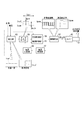
- FIG. 1 is a schematic view showing an automatic transmission to which the current control device of the first embodiment is applied
- FIG. 2 is a schematic view showing the hydraulic circuit of FIG.
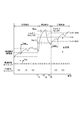
- FIG. 3 is a first time chart for explaining current control performed by the current control device of FIG.
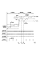
- FIG. 4 is a second time chart for explaining the current control performed by the current control device of FIG.
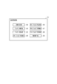
- FIG. 5 is a block diagram for explaining functional units included in the current control device of FIG. 6 is a block diagram for explaining the transient control unit of FIG.
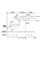
- FIG. 7 is a first time chart showing the excitation current of the solenoid when the current control device of FIG. 1 executes transient control
- FIG. 1 is a schematic view showing an automatic transmission to which the current control device of the first embodiment is applied
- FIG. 2 is a schematic view showing the hydraulic circuit of FIG.
- FIG. 3 is a first time chart for explaining current control performed by the current control device of FIG.
- FIG. 4 is a second time chart for explaining the current control performed by the current control device of
- FIG. 8 is a second time chart showing the excitation current of the solenoid when the current control device of FIG. 1 executes transient control
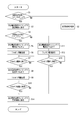
- FIG. 9 is a flowchart illustrating processing executed by the current control device of FIG. 1 for steady control and transient control
- FIG. 10 is a first time chart for explaining current control performed by the current control device according to the second embodiment
- FIG. 11 is a second time chart for explaining the current control performed by the current control device of the second embodiment
- FIG. 12 is a first time chart for explaining current control performed by the current control device of the third embodiment
- FIG. 13 is a second time chart for illustrating current control performed by the current control device according to the third embodiment.
- the current control device of the first embodiment is applied to an automatic transmission shown in FIG.
- the automatic transmission 10 includes a transmission mechanism 11, a hydraulic circuit 12, and a current control device 13.
- the transmission mechanism 11 has a plurality of friction elements 21 to 26, which are, for example, clutches and brakes, and the transmission elements are gradually changed by selective engagement of the friction elements 21 to 26.
- the hydraulic circuit 12 has a plurality of linear solenoid valves 31 to 36 that regulate the pressure of hydraulic oil fed from the oil pump 28 and supply the pressure to the friction elements 21 to 26.
- the linear solenoid valve 31 has a sleeve 41, a spool 42 as a valve body, and a solenoid 43 for driving the spool 42.
- the plunger 44 inside the solenoid 43 moves in the axial direction according to the magnitude of the exciting current of the solenoid 43.
- the spool 42 moves in the axial direction together with the movable core 44, and changes the output hydraulic pressure according to the axial position.
- the damper 45 and the throttle valve 46 are for reducing the pulsation of the hydraulic pressure.
- the current control device 13 includes a microcomputer 51, a drive circuit 52, and the like.
- the microcomputer 51 executes program processing based on detection values of various sensors to calculate the target values of the output hydraulic pressure of the linear solenoid valves 31 to 36 and the target current of the corresponding solenoid 43, and the target current is calculated according to the target current.
- Output a driving signal.
- the drive circuit 52 energizes or deenergizes the solenoid 43 according to the drive signal.
- the current control device 13 controls the excitation current of the solenoid 43.
- the current control performed by the current controller 13 includes steady-state control and transient control.
- Steady-state control is control that is executed when the target current is constant, and the operation of energizing the solenoid 43 and then de-energizing is repeated in a PWM cycle to make the average value of the excitation current of the solenoid 43 close to the target current. keep.
- the average value of the excitation current is periodically changed between “target current + dither amplitude” to “target current ⁇ dither amplitude” in a dither cycle longer than the PWM cycle.
- Transient control is control that is executed when the target current is changed, and changes the exciting current as quickly as possible to the vicinity of the target current after the change.
- the full on state means that the solenoid 43 is always energized.
- the full off state means that the solenoid 43 is always deenergized.
- the full on state is maintained until the excitation current reaches or exceeds the full on threshold.
- the full off state is maintained until the excitation current falls below the full off threshold.
- FIG. 4 when the target current is changed to the lower side, the solenoid 43 is fully turned off. After transient control, current control is transferred to steady state control.
- the current control device 13 includes a setting unit 55, a dither applying unit 56, a current acquisition unit 57, a current comparison unit 58, a steady control unit 59, and a transient control unit 61.
- the setting unit 55 sets a PWM cycle Tpwm (or a PWM frequency), a dither cycle Tdth (or a dither frequency), a dither amplitude Adth, a target current Iref, a full on threshold THon, and a full off threshold THoff.
- the dither amplitude Adth is set according to the oil temperature of the hydraulic circuit 12 and the voltage of the current control device 13.
- the full on threshold THon is set to “target current Iref + dither amplitude Adth”.
- the full off threshold THoff is set to “target current Iref ⁇ dither amplitude Adth”.
- the dither applying unit 56 generates a drive signal Spwm (that is, a PWM signal) to change the excitation current cyclically at the dither cycle Tdth during steady control, “target current Iref + dither amplitude Adth”. To “target current Iref ⁇ dither amplitude Adth” periodically.
- a drive signal Spwm that is, a PWM signal
- the current acquisition unit 57 acquires an excitation current at each current acquisition timing that arrives in a current acquisition cycle Tad shorter than the PWM cycle Tpwm.
- the current acquisition period Tad is about 1 ⁇ 4 of the PWM period Tpwm.
- the current comparison unit 58 compares the average value of the excitation current in a predetermined period with the command current Icom. This comparison is performed at the F / B calculation timing of FIG. 7 and FIG.
- the steady control unit 59 generates and outputs the drive signal Spwm based on the command current Icom so as to reduce the difference between the average value of the excitation current and the command current Icom, and executes steady control.
- the transient control unit 61 executes transient control.
- the transient control unit 61 includes a target determination unit 62, a full on control unit 63, a full on determination unit 64, a first full off control unit 65, a first full off determination unit 66, a second full off control unit 67, a second full off determination unit 68, and A control transition unit 69 is included.
- the target determination unit 62 determines whether the target current Iref has been changed for each predetermined target determination period shorter than the PWM period Tpwm. The target determination period is shorter than the current acquisition period Tad.
- the target current Iref is changed at time point t1, and the target determination unit 62 determines the target change between time points t1 and t2.
- the target current Iref is changed at time t11, and the target determination unit 62 determines the target change between time t11 and t12.
- the full-on control unit 63 causes the solenoid 43 to be fully on at the first timing that arrives at a predetermined control transition cycle shorter than the PWM cycle Tpwm after the target current Iref is changed to the up side.
- the full on state is 100% duty ratio.
- the control transition period is the same as the current acquisition period Tad.
- the full on state is started at time t2.
- the full-on determination unit 64 determines whether the excitation current is equal to or higher than the full-on threshold THon larger than the target current Iref. In FIG. 7, the excitation current becomes equal to or higher than the full on threshold THon at time t3, and the full on determination unit 64 determines that the full on threshold THon is equal to or higher between time t3 and t4.
- the first full off control unit 65 causes the solenoid 43 to be fully off at the first timing that arrives at a predetermined energization switching cycle shorter than the PWM cycle Tpwm after the excitation current becomes equal to or higher than the full on threshold THon.
- the duty ratio is 0%.
- the energization switching cycle is the same as the current acquisition cycle Tad.
- the full off state is started at time t4.
- the first full off determination unit 66 determines whether or not the excitation current has become equal to or less than the full off threshold THoff smaller than the target current Iref. In FIG. 7, the excitation current becomes equal to or less than the full off threshold THoff at time t5, and it is determined that the first full off determination unit 66 becomes equal to or less than the full off threshold THoff between time t5 and t6.
- the second full off control unit 67 causes the solenoid 43 to be fully off at the first timing that arrives in the control transition period.
- the full off state is started at time t12.
- the second full off determination unit 68 determines whether the excitation current has become equal to or less than the full off threshold THoff when the second full off control unit 67 is in the full off state. In FIG. 8, it is determined that the excitation current becomes equal to or less than the full off threshold THoff at time t13, and the second full off determination unit 68 becomes equal to or less than the full off threshold THoff between time t13 and t14.
- the control transition unit 69 shifts to steady-state control at the first timing that arrives in the control transition cycle.
- the transition to the steady control means that the full off state by the first full off control unit 65 or the second full off control unit 67 is ended, and execution of the steady control by the steady control unit 59 is permitted.
- steady control is entered at time t6, and in FIG. 8 steady control is entered at time t14.
- the steady control unit 59 executes steady control with the PWM cycle Tpwm newly reset from time t6 to time t14.
- the functional units 55 to 59 and 61 to 69 included in the current control device 13 may be realized by hardware processing by a dedicated logic circuit, or are stored in advance in a memory such as a computer readable non-transitory tangible recording medium
- the program may be realized by software processing by execution by a CPU, or may be realized by a combination of both. It is possible to appropriately select which part of the functional units 55 to 59 and 61 to 69 is realized by hardware processing and which part is realized by software processing.
- S7 it is determined whether the exciting current has become equal to or more than the full on threshold THon. If the excitation current has become equal to or higher than the full on threshold THon (S7: YES), the process proceeds to S8. If the excitation current is smaller than the full on threshold THon (S7: NO), the process repeats S7.
- S10 it is determined whether the excitation current has become equal to or less than the full off threshold THoff. If the excitation current has become equal to or less than the full off threshold THoff (S10: YES), the process proceeds to S14. When the excitation current is larger than the full off threshold THoff (S10: NO), the process repeats S10.
- S13 it is determined whether the excitation current has become equal to or less than the full off threshold THoff. If the excitation current has become equal to or less than the full off threshold THoff (S13: YES), the process proceeds to S14. If the excitation current is larger than the full off threshold THoff (S13: NO), the process repeats S13.
- the excitation current is changed to a threshold (that is, full on threshold THon or full off threshold THoff) before the target current Iref is exceeded.
- a threshold that is, full on threshold THon or full off threshold THoff
- the exciting current becomes equal to or higher than the full on threshold THon or lower than the full off threshold THoff
- the current supply is stopped at a relatively early timing. This allows the spool 42 to be quickly stopped in the desired overstroke condition. Therefore, the overshoot of the output hydraulic pressure can be suitably controlled.
- the exciting current can be largely changed to the full off threshold THoff relatively quickly after reaching the full on threshold THon, so that the spool 42 can be quickly returned to the steady position from the overstroke state. it can.
- the excitation current is changed relatively largely to cross the full on threshold THon and the full off threshold THoff, the dynamic friction state of the spool 42 is maintained. Therefore, it is possible to suppress the occurrence of overshooting of the output hydraulic pressure due to the operation delay of the spool 42.
- the excitation current is changed relatively largely so as to cross the full off threshold THoff. Therefore, the dynamic friction state of the spool 42 is maintained. Therefore, it is possible to suppress the occurrence of overshooting of the output hydraulic pressure due to the operation delay of the spool 42.
- the full on threshold THon is “target current Iref + dither amplitude Adth”
- the full off threshold THoff is “target current Iref ⁇ dither amplitude Adth”. Therefore, the full on threshold THon and the full off threshold THoff are set according to the dither amplitude Adth. Further, the control transition period and the energization switching period are the same as the current acquisition period. Therefore, transition of current control and switching of energization are performed without waiting for the timing at which the PWM cycle is completed.
- the setting unit sets the full on threshold THon and the full off threshold THoff to the change width of the target current Iref, the oil temperature of the hydraulic circuit 12, and the voltage of the current control device 13. Set accordingly.
- the full on threshold THon and the full off threshold THoff are set to be smaller as the change width of the target current Iref, the oil temperature of the hydraulic circuit 12 and the voltage of the current control device 13 are larger.
- the full-on control unit arrives at the first timing (control transition timing) arriving at a control transition period shorter than the current acquisition period Tad. Set to full on with).
- the first full-off control unit causes the solenoid 43 to be fully-off at the first timing (energization switching timing) that arrives at the energization switching cycle shorter than the current acquisition cycle Tad after the excitation current reaches the full on threshold THon. .
- the second full-off control unit receives the first timing (control transition timing) that arrives at the control transition period shorter than the current acquisition period Tad. Make it full off. Also, as shown in FIG. 12 and FIG. 13, the control transition section receives the first timing (control transition timing) that arrives at a control transition cycle shorter than the current acquisition cycle Tad after the excitation current becomes equal to or less than the full off threshold THoff. Transition to steady state control.
- the spool 42 can be controlled more quickly in an optimal state, and hydraulic performance can be improved.
- a normal control unit that performs the same current control as the steady control unit when the target current is changed may be newly provided. And the control content at the time of transient control may be changed according to the change width of the target current. For example, when the change width of the target current is smaller than a predetermined value, the normal control unit executes current control, and when the change width of the target current is equal to or larger than the predetermined value, the full on control unit 63, the full on determination unit 64, the first The full off control unit 65, the first full off determination unit 66, the second full off control unit 67, and the second full off determination unit 68 may be configured to execute current control.
- the full on threshold and the full off threshold may be set in accordance with any one or more of the change width of the target current, the oil temperature of the hydraulic circuit, and the voltage of the current control device.
- the current control device may be applied not only to linear solenoid valves but also to other types of solenoid valves.
- the solenoid valve is not limited to the spool type, and may be another type of valve.
- the current control device is not limited to the hydraulic pressure control, and may control another control amount.
Landscapes
- Engineering & Computer Science (AREA)
- General Engineering & Computer Science (AREA)
- Physics & Mathematics (AREA)
- Mechanical Engineering (AREA)
- Electromagnetism (AREA)
- General Physics & Mathematics (AREA)
- Power Engineering (AREA)
- Magnetically Actuated Valves (AREA)
Abstract
電流取得部(57)は、励磁電流を取得する。定常制御部(59)は、励磁電流の平均値を指令電流付近に保つ。目標判定部(62)は、定常制御時、目標電流が変更されたか否かを判定する。フルオン制御部(63)は、目標電流が上げ側に変更された後、制御移行周期で到来する最初のタイミングでソレノイド(43)をフルオン状態にする。フルオン判定部(64)は、励磁電流がフルオン閾値以上になったか否かを判定する。第1フルオフ制御部(65)は、励磁電流がフルオン閾値以上になった後、通電切替周期で到来する最初のタイミングでソレノイド(43)をフルオフ状態にする。第1フルオフ判定部(66)は、励磁電流がフルオフ閾値以下になったか否かを判定する。制御移行部(69)は、励磁電流がフルオフ閾値以下になった後、制御移行周期で到来する最初のタイミングで定常制御に移行する。
Description
本出願は、2017年9月25日に出願された特許出願番号2017-183324号に基づくものであり、ここにその記載内容を援用する。
本開示は、ソレノイドバルブのソレノイドの電流を制御する電流制御装置に関する。
従来、ソレノイドの電流を制御する技術として特許文献1に開示されたものが知られている。特許文献1の電流制御装置が実行する電流制御モードには、定常モードと過渡モードがある。
定常モードは、目標電流が一定であるときに実行される。この定常モードでは、励磁電流の平均値が目標電流と一致するように、電流のオンオフ(すなわち、通電・非通電)が所定のPWM周期で繰り返される。
定常モードは、目標電流が一定であるときに実行される。この定常モードでは、励磁電流の平均値が目標電流と一致するように、電流のオンオフ(すなわち、通電・非通電)が所定のPWM周期で繰り返される。
過渡モードは、目標電流が変更されたときに実行される。この過渡モードでは、電流が目標電流までフルオンされ、目標電流に到達したら定常モードのPWM周期よりも短い周期で電流のオンオフが繰り返され、定常モードのPWM周期と再同期させる準備がなされる。定常モードのPWM周期と合うタイミングになったとき、定常モードへの移行が行われる。
ところで、特許文献1に開示されている電流制御技術をソレノイドバルブに適用することが考えられる。
しかし、特許文献1では、過渡モードで電流がフルオンされた後に目標電流でオフされる。そのため、ソレノイドバルブに適用した場合、弁体が所望のオーバーストローク状態(すなわち、高応答を実現するための適切な位置)まで到達できず、制御量の変動遅れが発生する懸念がある。
しかし、特許文献1では、過渡モードで電流がフルオンされた後に目標電流でオフされる。そのため、ソレノイドバルブに適用した場合、弁体が所望のオーバーストローク状態(すなわち、高応答を実現するための適切な位置)まで到達できず、制御量の変動遅れが発生する懸念がある。
また、特許文献1では、過渡モードから定常モードに移行するとき、定常モードのPWM周期と合うタイミングになるまで比較的早い周波数で電流のオンオフを繰り返す待機期間がある。そのため、ソレノイドバルブに適用した場合、待機期間中の電流振幅がとても小さいために弁体が追従できず、弁体の動摩擦状態が維持されない。これが弁体の作動遅れにつながり、制御量のオーバーシュートが大きくなる懸念がある。
本開示は、上述の点に鑑みてなされたものであり、その目的は、制御量の応答性を高めるとともに制御量のオーバーシュートを抑制することができるソレノイドの電流制御装置を提供することである。
本開示の第1態様および第2態様の電流制御装置は、電流取得部と、定常制御部と、目標判定部とを備えている。
電流取得部は、ソレノイドの励磁電流を取得する。
定常制御部は、ソレノイドを通電したのち非通電にする作動を所定のオンオフ周期で繰り返して、励磁電流の平均値を目標電流付近に保つ定常制御を行う。
目標判定部は、定常制御が行われているとき、オンオフ周期よりも短い所定の目標判定周期ごとに目標電流が変更されたか否かを判定する。
電流取得部は、ソレノイドの励磁電流を取得する。
定常制御部は、ソレノイドを通電したのち非通電にする作動を所定のオンオフ周期で繰り返して、励磁電流の平均値を目標電流付近に保つ定常制御を行う。
目標判定部は、定常制御が行われているとき、オンオフ周期よりも短い所定の目標判定周期ごとに目標電流が変更されたか否かを判定する。
第1態様の電流制御装置は、フルオン制御部と、フルオン判定部と、フルオフ制御部と、フルオフ判定部と、制御移行部とをさらに備えている。
フルオン制御部は、目標電流が上げ側に変更された後、オンオフ周期よりも短い所定の制御移行周期で到来する最初のタイミングでソレノイドを常に通電するフルオン状態にする。
フルオン制御部は、目標電流が上げ側に変更された後、オンオフ周期よりも短い所定の制御移行周期で到来する最初のタイミングでソレノイドを常に通電するフルオン状態にする。
フルオン判定部は、フルオン状態であるとき、励磁電流が目標電流よりも大きいフルオン閾値以上になったか否かを判定する。
フルオフ制御部は、励磁電流がフルオン閾値以上になった後、オンオフ周期よりも短い所定の通電切替周期で到来する最初のタイミングでソレノイドを常に非通電とするフルオフ状態にする。
フルオフ制御部は、励磁電流がフルオン閾値以上になった後、オンオフ周期よりも短い所定の通電切替周期で到来する最初のタイミングでソレノイドを常に非通電とするフルオフ状態にする。
フルオフ判定部は、フルオフ状態であるとき、励磁電流が目標電流よりも小さいフルオフ閾値以下になったか否かを判定する。
制御移行部は、励磁電流がフルオフ閾値以下になった後、制御移行周期で到来する最初のタイミングで定常制御に移行する。
制御移行部は、励磁電流がフルオフ閾値以下になった後、制御移行周期で到来する最初のタイミングで定常制御に移行する。
第2態様の電流制御装置は、フルオフ制御部と、フルオフ判定部と、制御移行部とをさらに備えている。
フルオフ制御部は、目標電流が下げ側に変更された後、オンオフ周期よりも短い所定の制御移行周期で到来する最初のタイミングでソレノイドを常に非通電とするフルオフ状態にする。
フルオフ制御部は、目標電流が下げ側に変更された後、オンオフ周期よりも短い所定の制御移行周期で到来する最初のタイミングでソレノイドを常に非通電とするフルオフ状態にする。
フルオフ判定部は、フルオフ状態であるとき、励磁電流が目標電流よりも小さいフルオフ閾値以下になったか否かを判定する。
制御移行部は、励磁電流がフルオフ閾値以下になった後、制御移行周期で到来する最初のタイミングで定常制御に移行する。
制御移行部は、励磁電流がフルオフ閾値以下になった後、制御移行周期で到来する最初のタイミングで定常制御に移行する。
以上より、第1態様の電流制御装置は以下(A)~(D)、(F)の効果を得ることができ、また、第2態様の電流制御装置は以下(A)~(C)、(E)~(F)の効果を得ることができる。
(A)目標電流が変更された後、オンオフ周期が完了するタイミングを待たずにフルオン状態またはフルオフ状態にされるので、定常制御から過渡制御へ素早く移行することができる。
(A)目標電流が変更された後、オンオフ周期が完了するタイミングを待たずにフルオン状態またはフルオフ状態にされるので、定常制御から過渡制御へ素早く移行することができる。
(B)過渡制御に移行したあと、励磁電流が目標電流を越えた先にある閾値(すなわち、フルオン閾値またはフルオフ閾値)まで変化させられるので、弁体を所望のオーバーストローク状態まで到達させることができる。そのため、制御量の変動遅れ(すなわち、立ち上がり遅れ又は立ち下がり遅れ)が抑制され、応答性を高めることができる。
(C)励磁電流がフルオン閾値以上またはフルオフ閾値以下になると比較的早いタイミングで通電が止められるので、弁体を所望のオーバーストローク状態で素早く止めることができる。そのため、制御量のオーバーシュートを好適に制御することができる。
(C)励磁電流がフルオン閾値以上またはフルオフ閾値以下になると比較的早いタイミングで通電が止められるので、弁体を所望のオーバーストローク状態で素早く止めることができる。そのため、制御量のオーバーシュートを好適に制御することができる。
(D)励磁電流がフルオン閾値到達後に比較的早くフルオフ閾値まで大きく変化させられるので、弁体をオーバーストローク状態から素早く定常位置に戻すことができる。また、励磁電流がフルオン閾値およびフルオフ閾値を跨ぐように比較的大きく変化させられるので、弁体の動摩擦状態が維持される。そのため、弁体の作動遅れに起因した制御量のオーバーシュートの発生を抑制することができる。
(E)励磁電流がフルオフ閾値を跨ぐように比較的大きく変化させられるので、弁体の動摩擦状態が維持される。そのため、弁体の作動遅れに起因した制御量のオーバーシュートの発生を抑制することができる。
(F)励磁電流がフルオフ閾値以下になると、オンオフ周期のタイミングとは関係なく比較的早いタイミングで通常制御に移行されるので、過渡制御から定常制御へ素早く移行することができる。
(F)励磁電流がフルオフ閾値以下になると、オンオフ周期のタイミングとは関係なく比較的早いタイミングで通常制御に移行されるので、過渡制御から定常制御へ素早く移行することができる。
ここで、「オーバーシュート」とは制御量の行き過ぎのことである。つまり、制御量が目標に向かって変化していくとき、目標を越えるように変化することである。現状の制御量よりも目標が大きい場合、制御量が目標よりも大きくなることである。また、現状の制御量よりも目標が小さい場合、制御量が目標よりも小さくなることである。
本開示についての上記目的およびその他の目的、特徴や利点は、添付の図面を参照しながら下記の詳細な記述により、より明確になる。その図面は、
図1は、第1実施形態の電流制御装置が適用された自動変速機を示す模式図であり、
図2は、図1の油圧回路を示す模式図であり、
図3は、図1の電流制御装置が実行する電流制御を説明するための第1のタイムチャートであり、
図4は、図1の電流制御装置が実行する電流制御を説明するための第2のタイムチャートであり、
図5は、図1の電流制御装置が備える機能部を説明するブロック図であり、
図6は、図5の過渡制御部を説明するブロック図であり、
図7は、図1の電流制御装置が過渡制御を実行するときのソレノイドの励磁電流を示す第1のタイムチャートであり、
図8は、図1の電流制御装置が過渡制御を実行するときのソレノイドの励磁電流を示す第2のタイムチャートであり、
図9は、図1の電流制御装置が定常制御および過渡制御のために実行する処理を説明するフローチャートであり、
図10は、第2実施形態の電流制御装置が実行する電流制御を説明するための第1のタイムチャートであり、
図11は、第2実施形態の電流制御装置が実行する電流制御を説明するための第2のタイムチャートであり、
図12は、第3実施形態の電流制御装置が実行する電流制御を説明するための第1のタイムチャートであり、
図13は、第3実施形態の電流制御装置が実行する電流制御を説明するための第2のタイムチャートである。
以下、複数の実施形態を図面に基づき説明する。実施形態同士で実質的に同一の構成には同一の符号を付して説明を省略する。
[第1実施形態]
第1実施形態の電流制御装置は、図1に示す自動変速機に適用されている。自動変速機10は、変速機構11、油圧回路12および電流制御装置13を備えている。
[第1実施形態]
第1実施形態の電流制御装置は、図1に示す自動変速機に適用されている。自動変速機10は、変速機構11、油圧回路12および電流制御装置13を備えている。
変速機構11は、例えばクラッチやブレーキ等からなる複数の摩擦要素21~26を有しており、各摩擦要素21~26が選択的に係合されることで変速比を段階的に変化させる。
油圧回路12は、オイルポンプ28から圧送された作動油を調圧して摩擦要素21~26に供給する複数のリニアソレノイドバルブ31~36を有している。
油圧回路12は、オイルポンプ28から圧送された作動油を調圧して摩擦要素21~26に供給する複数のリニアソレノイドバルブ31~36を有している。
図2に示すように、リニアソレノイドバルブ31は、スリーブ41と、弁体としてのスプール42と、スプール42を駆動するソレノイド43とを有している。ソレノイド43の内側のプランジャ44は、ソレノイド43の励磁電流の大きさに応じて軸方向に移動する。スプール42は、可動鉄心44と共に軸方向に移動し、軸方向位置に応じて出力油圧を変化させる。ダンパ45および絞り弁46は、油圧の脈動を低減するためのものである。
電流制御装置13は、マイクロコンピュータ51および駆動回路52などから構成されている。マイクロコンピュータ51は、各種センサの検出値に基づきプログラム処理を実行することにより、リニアソレノイドバルブ31~36の出力油圧の目標値およびそれに対応するソレノイド43の目標電流を算出し、この目標電流に応じた駆動信号を出力する。駆動回路52は、駆動信号に応じてソレノイド43を通電または非通電とする。電流制御装置13は、ソレノイド43の励磁電流を制御する。
<電流制御>
次に、電流制御装置13が実行する電流制御について図3、図4を参照して説明する。
電流制御装置13が実行する電流制御には、定常制御および過渡制御がある。
定常制御は、目標電流が一定であるときに実行される制御であり、ソレノイド43を通電したのち非通電にする作動をPWM周期で繰り返して、ソレノイド43の励磁電流の平均値を目標電流付近に保つ。本実施形態では、励磁電流の平均値は、PWM周期よりも長いディザ周期で「目標電流+ディザ振幅」から「目標電流-ディザ振幅」までの間で周期的に変化させられる。励磁電流をディザ周期で周期的に変化させることにより、スプール42が微振動し、スプール42の動摩擦状態が維持される。
次に、電流制御装置13が実行する電流制御について図3、図4を参照して説明する。
電流制御装置13が実行する電流制御には、定常制御および過渡制御がある。
定常制御は、目標電流が一定であるときに実行される制御であり、ソレノイド43を通電したのち非通電にする作動をPWM周期で繰り返して、ソレノイド43の励磁電流の平均値を目標電流付近に保つ。本実施形態では、励磁電流の平均値は、PWM周期よりも長いディザ周期で「目標電流+ディザ振幅」から「目標電流-ディザ振幅」までの間で周期的に変化させられる。励磁電流をディザ周期で周期的に変化させることにより、スプール42が微振動し、スプール42の動摩擦状態が維持される。
過渡制御は、目標電流が変更されたときに実行される制御であり、励磁電流を変更後の目標電流付近まで可及的に早く変化させる。図3に示すように、目標電流が上げ側に変更された場合、ソレノイド43をフルオン状態にしたあとフルオフ状態にする。フルオン状態とはソレノイド43を常に通電することである。フルオフ状態とはソレノイド43を常に非通電にすることである。フルオン状態は、励磁電流がフルオン閾値以上になるまで維持される。フルオフ状態は、励磁電流がフルオフ閾値以下になるまで維持される。図4に示すように、目標電流が下げ側に変更された場合、ソレノイド43をフルオフ状態にする。過渡制御の後、電流制御は定常制御に移行される。
<電流制御装置の機能部>
次に、電流制御装置13が備える機能部について図5~図8を参照して説明する。
電流制御装置13は、設定部55、ディザ付与部56、電流取得部57、電流比較部58、定常制御部59および過渡制御部61を備えている。
次に、電流制御装置13が備える機能部について図5~図8を参照して説明する。
電流制御装置13は、設定部55、ディザ付与部56、電流取得部57、電流比較部58、定常制御部59および過渡制御部61を備えている。
設定部55は、PWM周期Tpwm(またはPWM周波数)、ディザ周期Tdth(またはディザ周波数)、ディザ振幅Adth、目標電流Iref、フルオン閾値THonおよびフルオフ閾値THoffを設定する。例えば、ディザ振幅Adthは、油圧回路12の油温および電流制御装置13の電圧に応じて設定される。フルオン閾値THonは、「目標電流Iref+ディザ振幅Adth」に設定される。フルオフ閾値THoffは、「目標電流Iref-ディザ振幅Adth」に設定される。
ディザ付与部56は、定常制御時に励磁電流をディザ周期Tdthで周期的に変化させるために、駆動信号Spwm(すなわちPWM信号)を生成する元となる指令電流Icomを「目標電流Iref+ディザ振幅Adth」から「目標電流Iref-ディザ振幅Adth」までの間で周期的に変化させる。
電流取得部57は、PWM周期Tpwmよりも短い電流取得周期Tadで到来する電流取得タイミングごとに励磁電流を取得する。本実施形態では、例えば電流取得周期TadはPWM周期Tpwmの1/4程度である。
電流比較部58は、所定期間の励磁電流の平均値と指令電流Icomとを比較する。この比較は図7、図8のF/B演算タイミングで行われる。
定常制御部59は、指令電流Icomに基づき、励磁電流の平均値と指令電流Icomとの差が小さくなるように駆動信号Spwmを生成して出力し、定常制御を実行する。
電流比較部58は、所定期間の励磁電流の平均値と指令電流Icomとを比較する。この比較は図7、図8のF/B演算タイミングで行われる。
定常制御部59は、指令電流Icomに基づき、励磁電流の平均値と指令電流Icomとの差が小さくなるように駆動信号Spwmを生成して出力し、定常制御を実行する。
過渡制御部61は、過渡制御を実行する。過渡制御部61は、目標判定部62、フルオン制御部63、フルオン判定部64、第1フルオフ制御部65、第1フルオフ判定部66、第2フルオフ制御部67、第2フルオフ判定部68、および制御移行部69を含む。
目標判定部62は、定常制御が行われているとき、PWM周期Tpwmよりも短い所定の目標判定周期ごとに目標電流Irefが変更されたか否かを判定する。目標判定周期は、電流取得周期Tadよりも短い。図7では、時点t1で目標電流Irefが変更され、時点t1~t2の間で目標判定部62が目標変更を判定する。図8では、時点t11で目標電流Irefが変更され、時点t11~t12の間で目標判定部62が目標変更を判定する。
目標判定部62は、定常制御が行われているとき、PWM周期Tpwmよりも短い所定の目標判定周期ごとに目標電流Irefが変更されたか否かを判定する。目標判定周期は、電流取得周期Tadよりも短い。図7では、時点t1で目標電流Irefが変更され、時点t1~t2の間で目標判定部62が目標変更を判定する。図8では、時点t11で目標電流Irefが変更され、時点t11~t12の間で目標判定部62が目標変更を判定する。
フルオン制御部63は、目標電流Irefが上げ側に変更された後、PWM周期Tpwmよりも短い所定の制御移行周期で到来する最初のタイミングでソレノイド43をフルオン状態にする。フルオン状態はデューティ比100%となる。本実施形態では、制御移行周期は、電流取得周期Tadと同じである。図7では時点t2でフルオン状態が開始されている。
フルオン判定部64は、フルオン制御部63によるフルオン状態であるとき、励磁電流が目標電流Irefよりも大きいフルオン閾値THon以上になったか否かを判定する。図7では、時点t3で励磁電流がフルオン閾値THon以上になり、時点t3~t4の間でフルオン判定部64がフルオン閾値THon以上になったことを判定する。
第1フルオフ制御部65は、励磁電流がフルオン閾値THon以上になった後、PWM周期Tpwmよりも短い所定の通電切替周期で到来する最初のタイミングでソレノイド43をフルオフ状態にする。フルオフ状態はデューティ比0%となる。本実施形態では、通電切替周期は、電流取得周期Tadと同じである。図7では時点t4でフルオフ状態が開始されている。
第1フルオフ判定部66は、第1フルオフ制御部65によるフルオフ状態であるとき、励磁電流が目標電流Irefよりも小さいフルオフ閾値THoff以下になったか否かを判定する。図7では、時点t5で励磁電流がフルオフ閾値THoff以下になり、時点t5~t6の間で第1フルオフ判定部66がフルオフ閾値THoff以下になったことを判定する。
第2フルオフ制御部67は、目標電流Irefが下げ側に変更された後、制御移行周期で到来する最初のタイミングでソレノイド43をフルオフ状態にする。図8では時点t12でフルオフ状態が開始されている。
第2フルオフ判定部68は、第2フルオフ制御部67によるフルオフ状態であるとき、励磁電流がフルオフ閾値THoff以下になったか否かを判定する。図8では、時点t13で励磁電流がフルオフ閾値THoff以下になり、時点t13~t14の間で第2フルオフ判定部68がフルオフ閾値THoff以下になったことを判定する。
第2フルオフ判定部68は、第2フルオフ制御部67によるフルオフ状態であるとき、励磁電流がフルオフ閾値THoff以下になったか否かを判定する。図8では、時点t13で励磁電流がフルオフ閾値THoff以下になり、時点t13~t14の間で第2フルオフ判定部68がフルオフ閾値THoff以下になったことを判定する。
制御移行部69は、励磁電流がフルオフ閾値THoff以下になった後、制御移行周期で到来する最初のタイミングで定常制御に移行する。定常制御に移行するとは、第1フルオフ制御部65または第2フルオフ制御部67によるフルオフ状態を終了させて、定常制御部59による定常制御の実行を許可することを意味する。図7では、時点t6で定常制御に移行され、図8では、時点t14で定常制御に移行されている。このとき定常制御部59は、時点t6、t14から新たにリセットされたPWM周期Tpwmで定常制御を実行する。
電流制御装置13が有する各機能部55~59、61~69は、専用の論理回路によるハードウェア処理により実現されてもよいし、コンピュータ読み出し可能非一時的有形記録媒体等のメモリに予め記憶されたプログラムをCPUで実行することによるソフトウェア処理により実現されてもよいし、あるいは、両者の組み合わせで実現されてもよい。各機能部55~59、61~69のうちどの部分をハードウェア処理により実現し、どの部分をソフトウェア処理により実現するかは、適宜選択可能である。
<電流制御装置が実行する処理>
次に、電流制御装置13が定常制御および過渡制御のために実行する処理について図9を参照して説明する。図9に示すルーチンは、電流制御装置13の起動後に定常制御が実行開始されてから、目標判定周期で繰り返し実行される。以降、「S」はステップを意味する。
次に、電流制御装置13が定常制御および過渡制御のために実行する処理について図9を参照して説明する。図9に示すルーチンは、電流制御装置13の起動後に定常制御が実行開始されてから、目標判定周期で繰り返し実行される。以降、「S」はステップを意味する。
図9のS1では、目標電流Irefが変更されたか否かが判定される。
目標電流Irefが変更されず一定である場合(S1:YES)、処理はS2に移行する。
目標電流Irefが変更された場合(S1:NO)、処理はS3に移行する。
目標電流Irefが変更されず一定である場合(S1:YES)、処理はS2に移行する。
目標電流Irefが変更された場合(S1:NO)、処理はS3に移行する。
S2では、定常制御が維持される。S2の後、処理は図9のルーチンを抜ける。
S3では、次の電流取得タイミングで過渡制御に移行される。過渡制御に移行するとは、フルオン制御部63または第2フルオフ制御部67による電流制御の実行を許可することを意味する。S3の後、処理はS4に移行する。
S3では、次の電流取得タイミングで過渡制御に移行される。過渡制御に移行するとは、フルオン制御部63または第2フルオフ制御部67による電流制御の実行を許可することを意味する。S3の後、処理はS4に移行する。
S4では、目標電流Irefが上げ側に変更されたか否かが判定される。
目標電流Irefの変更が上げ側である場合(S4:YES)、処理はS5に移行する。
目標電流Irefの変更が上げ側ではない(すなわち、下げ側である)である場合(S4:NO)、処理はS11に移行する。
目標電流Irefの変更が上げ側である場合(S4:YES)、処理はS5に移行する。
目標電流Irefの変更が上げ側ではない(すなわち、下げ側である)である場合(S4:NO)、処理はS11に移行する。
S5では、次の電流取得タイミングでソレノイド43がフルオン状態にされる。S5の後、処理はS6に移行する。
S6では、フルオン閾値THonが設定される。S6の後、処理はS7に移行する。
S6では、フルオン閾値THonが設定される。S6の後、処理はS7に移行する。
S7では、励磁電流がフルオン閾値THon以上になったか否かが判定される。
励磁電流がフルオン閾値THon以上になった場合(S7:YES)、処理はS8に移行する。
励磁電流がフルオン閾値THonよりも小さい場合(S7:NO)、処理はS7を繰り返す。
励磁電流がフルオン閾値THon以上になった場合(S7:YES)、処理はS8に移行する。
励磁電流がフルオン閾値THonよりも小さい場合(S7:NO)、処理はS7を繰り返す。
S8では、次の電流取得タイミングでソレノイド43がフルオフ状態にされる。S8の後、処理はS9に移行する。
S9では、フルオフ閾値THoffが設定される。S9の後、処理はS10に移行する。
S9では、フルオフ閾値THoffが設定される。S9の後、処理はS10に移行する。
S10では、励磁電流がフルオフ閾値THoff以下になったか否かが判定される。
励磁電流がフルオフ閾値THoff以下になった場合(S10:YES)、処理はS14に移行する。
励磁電流がフルオフ閾値THoffよりも大きい場合(S10:NO)、処理はS10を繰り返す。
励磁電流がフルオフ閾値THoff以下になった場合(S10:YES)、処理はS14に移行する。
励磁電流がフルオフ閾値THoffよりも大きい場合(S10:NO)、処理はS10を繰り返す。
S11では、次の電流取得タイミングでソレノイド43がフルオフ状態にされる。S11の後、処理はS12に移行する。
S12では、フルオフ閾値THoffが設定される。S12の後、処理はS13に移行する。
S12では、フルオフ閾値THoffが設定される。S12の後、処理はS13に移行する。
S13では、励磁電流がフルオフ閾値THoff以下になったか否かが判定される。
励磁電流がフルオフ閾値THoff以下になった場合(S13:YES)、処理はS14に移行する。
励磁電流がフルオフ閾値THoffよりも大きい場合(S13:NO)、処理はS13を繰り返す。
励磁電流がフルオフ閾値THoff以下になった場合(S13:YES)、処理はS14に移行する。
励磁電流がフルオフ閾値THoffよりも大きい場合(S13:NO)、処理はS13を繰り返す。
S14では、次の電流取得タイミングで定常制御に移行される。このときの定常制御は、新たにリセットされたPWM周期Tpwmで実行開始される。S14の後、処理は図9のルーチンを抜ける。
<効果>
以上説明したように、第1実施形態では、目標電流Irefが変更された後、PWM周期が完了するタイミングを待たずにフルオン状態またはフルオフ状態にされる。そのため、定常制御から過渡制御へ素早く移行することができる。
以上説明したように、第1実施形態では、目標電流Irefが変更された後、PWM周期が完了するタイミングを待たずにフルオン状態またはフルオフ状態にされる。そのため、定常制御から過渡制御へ素早く移行することができる。
また、過渡制御に移行したあと、励磁電流が目標電流Irefを越えた先にある閾値(すなわち、フルオン閾値THonまたはフルオフ閾値THoff)まで変化させられる。これにより、スプール42を所望のオーバーストローク状態まで到達させることができる。そのため、出力油圧の変動遅れが抑制され、応答性を高めることができる。
また、励磁電流がフルオン閾値THon以上またはフルオフ閾値THoff以下になると比較的早いタイミングで通電が止められる。これにより、スプール42を所望のオーバーストローク状態で素早く止めることができる。そのため、出力油圧のオーバーシュートを好適に制御することができる。
また、目標電流Irefが上げ側に変更された場合において、励磁電流がフルオン閾値THon到達後に比較的早くフルオフ閾値THoffまで大きく変化させられるので、スプール42をオーバーストローク状態から素早く定常位置に戻すことができる。また、励磁電流がフルオン閾値THonおよびフルオフ閾値THoffを跨ぐように比較的大きく変化させられるので、スプール42の動摩擦状態が維持される。そのため、スプール42の作動遅れに起因した出力油圧のオーバーシュートの発生を抑制することができる。
また、目標電流Irefが下げ側に変更された場合において、励磁電流がフルオフ閾値THoffを跨ぐように比較的大きく変化させられる。これにより、スプール42の動摩擦状態が維持される。そのため、スプール42の作動遅れに起因した出力油圧のオーバーシュートの発生を抑制することができる。
また、励磁電流がフルオフ閾値THoff以下になると、PWM周期Tpwmのタイミングとは関係なく比較的早いタイミングで通常制御に移行される。そのため、過渡制御から定常制御へ素早く移行することができる。
また、フルオン閾値THonは「目標電流Iref+ディザ振幅Adth」であり、フルオフ閾値THoffは「目標電流Iref-ディザ振幅Adth」である。そのため、ディザ振幅Adthに応じてフルオン閾値THonおよびフルオフ閾値THoffが設定される。
また、制御移行周期および通電切替周期は、電流取得周期と同じである。そのため、PWM周期が完了するタイミングを待たずに電流制御の移行および通電切替がなされる。
また、制御移行周期および通電切替周期は、電流取得周期と同じである。そのため、PWM周期が完了するタイミングを待たずに電流制御の移行および通電切替がなされる。
[第2実施形態]
第2実施形態では、図10、図11に示すように、設定部は、フルオン閾値THonおよびフルオフ閾値THoffを、目標電流Irefの変更幅、油圧回路12の油温および電流制御装置13の電圧に応じて設定する。目標電流Irefの変更幅、油圧回路12の油温および電流制御装置13の電圧が大きいほど、フルオン閾値THonおよびフルオフ閾値THoffは小さく設定される。
このようにソレノイド43や油圧回路12の仕様等に応じてフルオン閾値THonおよびフルオフ閾値THoffを設定することで、所望の油圧性能に調整することができる。
第2実施形態では、図10、図11に示すように、設定部は、フルオン閾値THonおよびフルオフ閾値THoffを、目標電流Irefの変更幅、油圧回路12の油温および電流制御装置13の電圧に応じて設定する。目標電流Irefの変更幅、油圧回路12の油温および電流制御装置13の電圧が大きいほど、フルオン閾値THonおよびフルオフ閾値THoffは小さく設定される。
このようにソレノイド43や油圧回路12の仕様等に応じてフルオン閾値THonおよびフルオフ閾値THoffを設定することで、所望の油圧性能に調整することができる。
[第3実施形態]
第3実施形態では、図12に示すように、フルオン制御部は、目標電流Irefが上げ側に変更された後、電流取得周期Tadよりも短い制御移行周期で到来する最初のタイミング(制御移行タイミング)でフルオン状態にする。
また、第1フルオフ制御部は、励磁電流がフルオン閾値THon以上になった後、電流取得周期Tadよりも短い通電切替周期で到来する最初のタイミング(通電切替タイミング)でソレノイド43をフルオフ状態にする。
第3実施形態では、図12に示すように、フルオン制御部は、目標電流Irefが上げ側に変更された後、電流取得周期Tadよりも短い制御移行周期で到来する最初のタイミング(制御移行タイミング)でフルオン状態にする。
また、第1フルオフ制御部は、励磁電流がフルオン閾値THon以上になった後、電流取得周期Tadよりも短い通電切替周期で到来する最初のタイミング(通電切替タイミング)でソレノイド43をフルオフ状態にする。
また、図13に示すように、第2フルオフ制御部は、目標電流Irefが下げ側に変更された後、電流取得周期Tadよりも短い制御移行周期で到来する最初のタイミング(制御移行タイミング)でフルオフ状態にする。
また、図12、図13に示すように、制御移行部は、励磁電流がフルオフ閾値THoff以下になった後、電流取得周期Tadよりも短い制御移行周期で到来する最初のタイミング(制御移行タイミング)で定常制御に移行する。
また、図12、図13に示すように、制御移行部は、励磁電流がフルオフ閾値THoff以下になった後、電流取得周期Tadよりも短い制御移行周期で到来する最初のタイミング(制御移行タイミング)で定常制御に移行する。
このように制御移行周期および通電切替周期を電流取得周期よりも短く設定することで、スプール42を最適な状態により素早く制御することができ、油圧性能を向上させることができる。
[他の実施形態]
他の実施形態では、目標電流が変更されたときに定常制御部と同様の電流制御を行う通常制御部が新たに設けられてもよい。そして、目標電流の変更幅に応じて過渡制御時の制御内容が変更されてもよい。例えば、目標電流の変更幅が所定値よりも小さい場合、通常制御部が電流制御を実行し、目標電流の変更幅が所定値以上である場合、フルオン制御部63、フルオン判定部64、第1フルオフ制御部65、第1フルオフ判定部66、第2フルオフ制御部67、第2フルオフ判定部68が電流制御を実行するように構成してもよい。
他の実施形態では、目標電流が変更されたときに定常制御部と同様の電流制御を行う通常制御部が新たに設けられてもよい。そして、目標電流の変更幅に応じて過渡制御時の制御内容が変更されてもよい。例えば、目標電流の変更幅が所定値よりも小さい場合、通常制御部が電流制御を実行し、目標電流の変更幅が所定値以上である場合、フルオン制御部63、フルオン判定部64、第1フルオフ制御部65、第1フルオフ判定部66、第2フルオフ制御部67、第2フルオフ判定部68が電流制御を実行するように構成してもよい。
他の実施形態では、フルオン閾値およびフルオフ閾値は、目標電流の変更幅、油圧回路の油温、および、電流制御装置の電圧のうちいずれか1つ以上に応じて設定されてもよい。
他の実施形態では、電流制御装置は、リニアソレノイドバルブに限らず、他の形式のソレノイドバルブに適用されてもよい。また、ソレノイドバルブは、スプール式に限らず、他の形式のバルブであってもよい。また、電流制御装置は、油圧制御に限らず、他の制御量を制御するものであってもよい。
他の実施形態では、電流制御装置は、リニアソレノイドバルブに限らず、他の形式のソレノイドバルブに適用されてもよい。また、ソレノイドバルブは、スプール式に限らず、他の形式のバルブであってもよい。また、電流制御装置は、油圧制御に限らず、他の制御量を制御するものであってもよい。
本開示は、実施形態に基づき記述された。しかしながら、本開示は当該実施形態および構造に限定されるものではない。本開示は、様々な変形例および均等の範囲内の変形をも包含する。また、様々な組み合わせおよび形態、さらには、それらに一要素のみ、それ以上、あるいはそれ以下、を含む他の組み合わせおよび形態も、本開示の範疇および思想範囲に入るものである。
Claims (12)
- ソレノイドバルブ(31~36)のソレノイド(43)の電流を制御する電流制御装置であって、
前記ソレノイドの励磁電流を取得する電流取得部(57)と、
前記ソレノイドを通電したのち非通電にする作動を所定のオンオフ周期で繰り返して、前記励磁電流の平均値を目標電流付近に保つ定常制御を行う定常制御部(59)と、
前記定常制御が行われているとき、前記オンオフ周期よりも短い所定の目標判定周期ごとに前記目標電流が変更されたか否かを判定する目標判定部(62)と、
前記目標電流が上げ側に変更された後、前記オンオフ周期よりも短い所定の制御移行周期で到来する最初のタイミングで前記ソレノイドを常に通電するフルオン状態にするフルオン制御部(63)と、
前記フルオン状態であるとき、前記励磁電流が前記目標電流よりも大きいフルオン閾値以上になったか否かを判定するフルオン判定部(64)と、
前記励磁電流が前記フルオン閾値以上になった後、前記オンオフ周期よりも短い所定の通電切替周期で到来する最初のタイミングで前記ソレノイドを常に非通電とするフルオフ状態にするフルオフ制御部(65)と、
前記フルオフ状態であるとき、前記励磁電流が前記目標電流よりも小さいフルオフ閾値以下になったか否かを判定するフルオフ判定部(66)と、
前記励磁電流が前記フルオフ閾値以下になった後、前記制御移行周期で到来する最初のタイミングで前記定常制御に移行する制御移行部(69)と、
を備える電流制御装置。 - 前記定常制御部は、前記励磁電流の平均値を前記オンオフ周期よりも長いディザ周期で「前記目標電流+ディザ振幅」から「前記目標電流-前記ディザ振幅」までの間で周期的に変化させ、
前記フルオン閾値は、「前記目標電流+前記ディザ振幅」であり、
前記フルオフ閾値は、「前記目標電流-前記ディザ振幅」である請求項1に記載の電流制御装置。 - 前記フルオン閾値および前記フルオフ閾値は、前記目標電流の変更幅、前記ソレノイドバルブが出力する流体の温度、および、前記電流制御装置の電圧の少なくとも1つに応じて設定される請求項1または2に記載の電流制御装置。
- 前記電流取得部は、前記オンオフ周期よりも短い電流取得周期で前記励磁電流を取得し、
前記制御移行周期および前記通電切替周期の一方、または両方は、前記電流取得周期と同じである請求項1~3のいずれか一項に記載の電流制御装置。 - 前記電流取得部は、前記オンオフ周期よりも短い電流取得周期で前記励磁電流を取得し、
前記制御移行周期および前記通電切替周期の一方、または両方は、前記電流取得周期よりも短い請求項1~3のいずれか一項に記載の電流制御装置。 - ソレノイドバルブのソレノイドの電流を制御する電流制御装置であって、
前記ソレノイドの励磁電流を取得する電流取得部と、
前記ソレノイドを通電したのち非通電にする作動を所定のオンオフ周期で繰り返して、前記励磁電流の平均値を目標電流付近に保つ定常制御を行う定常制御部と、
前記定常制御が行われているとき、前記オンオフ周期よりも短い所定の目標判定周期ごとに前記目標電流が変更されたか否かを判定する目標判定部と、
前記目標電流が下げ側に変更された後、前記オンオフ周期よりも短い所定の制御移行周期で到来する最初のタイミングで前記ソレノイドを常に非通電とするフルオフ状態にするフルオフ制御部(67)と、
前記フルオフ状態であるとき、前記励磁電流が前記目標電流よりも小さいフルオフ閾値以下になったか否かを判定するフルオフ判定部(68)と、
前記励磁電流が前記フルオフ閾値以下になった後、前記制御移行周期で到来する最初のタイミングで前記定常制御に移行する制御移行部と、
を備える電流制御装置。 - 前記定常制御部は、前記励磁電流の平均値を前記オンオフ周期よりも長いディザ周期で「前記目標電流+ディザ振幅」から「前記目標電流-前記ディザ振幅」までの間で周期的に変化させ、
前記フルオフ閾値は、「前記目標電流-前記ディザ振幅」である請求項6に記載の電流制御装置。 - 前記フルオフ閾値は、前記目標電流の変更幅、前記ソレノイドバルブが出力する流体の温度、および、前記電流制御装置の電圧の少なくとも1つに応じて設定される請求項6または7に記載の電流制御装置。
- 前記電流取得部は、前記オンオフ周期よりも短い電流取得周期で前記励磁電流を取得し、
前記制御移行周期は前記電流取得周期と同じである請求項6~8のいずれか一項に記載の電流制御装置。 - 前記電流取得部は、前記オンオフ周期よりも短い電流取得周期で前記励磁電流を取得し、
前記制御移行周期は前記電流取得周期よりも短い請求項6~8のいずれか一項に記載の電流制御装置。 - 前記ソレノイドバルブはスプール式である請求項1~10のいずれか一項に記載の電流制御装置。
- 前記ソレノイドバルブは油圧制御に用いられる請求項11に記載の電流制御装置。
Priority Applications (3)
| Application Number | Priority Date | Filing Date | Title |
|---|---|---|---|
| CN201880060422.4A CN111108315A (zh) | 2017-09-25 | 2018-09-18 | 电流控制装置 |
| DE112018005444.6T DE112018005444T8 (de) | 2017-09-25 | 2018-09-18 | Stromsteuervorrichtung |
| US16/812,616 US11549583B2 (en) | 2017-09-25 | 2020-03-09 | Current control device |
Applications Claiming Priority (2)
| Application Number | Priority Date | Filing Date | Title |
|---|---|---|---|
| JP2017183324A JP6769418B2 (ja) | 2017-09-25 | 2017-09-25 | 電流制御装置 |
| JP2017-183324 | 2017-09-25 |
Related Child Applications (1)
| Application Number | Title | Priority Date | Filing Date |
|---|---|---|---|
| US16/812,616 Continuation US11549583B2 (en) | 2017-09-25 | 2020-03-09 | Current control device |
Publications (1)
| Publication Number | Publication Date |
|---|---|
| WO2019059152A1 true WO2019059152A1 (ja) | 2019-03-28 |
Family
ID=65809782
Family Applications (1)
| Application Number | Title | Priority Date | Filing Date |
|---|---|---|---|
| PCT/JP2018/034378 Ceased WO2019059152A1 (ja) | 2017-09-25 | 2018-09-18 | 電流制御装置 |
Country Status (5)
| Country | Link |
|---|---|
| US (1) | US11549583B2 (ja) |
| JP (1) | JP6769418B2 (ja) |
| CN (1) | CN111108315A (ja) |
| DE (1) | DE112018005444T8 (ja) |
| WO (1) | WO2019059152A1 (ja) |
Cited By (1)
| Publication number | Priority date | Publication date | Assignee | Title |
|---|---|---|---|---|
| US20220181055A1 (en) * | 2020-12-08 | 2022-06-09 | Toyota Jidosha Kabushiki Kaisha | Controller and control method for linear solenoid valve |
Families Citing this family (2)
| Publication number | Priority date | Publication date | Assignee | Title |
|---|---|---|---|---|
| DE102016119027A1 (de) * | 2016-10-07 | 2018-04-12 | Chr. Mayr Gmbh + Co. Kg | Elektromagnetische Bremse mit einer steuerbaren Ankerscheibenbewegung |
| DE102018004989B3 (de) * | 2018-06-25 | 2019-09-12 | RUHR-UNIVERSITäT BOCHUM | Adaptiver Zweipunktregler und Verfahren zur adaptiven Zweipunktregelung |
Citations (3)
| Publication number | Priority date | Publication date | Assignee | Title |
|---|---|---|---|---|
| JP2837166B2 (ja) * | 1988-08-10 | 1998-12-14 | アイシン・エィ・ダブリュ株式会社 | 自動変速機用油圧制御装置 |
| JP2007501980A (ja) * | 2003-08-07 | 2007-02-01 | ローズマウント インコーポレイテッド | 零入力電流診断を備えたプロセス装置 |
| JP2018076918A (ja) * | 2016-11-09 | 2018-05-17 | 株式会社デンソー | 負荷駆動装置 |
Family Cites Families (27)
| Publication number | Priority date | Publication date | Assignee | Title |
|---|---|---|---|---|
| US5062050A (en) * | 1989-10-17 | 1991-10-29 | Borg-Warner Automotive, Inc. | Continuously variable transmission line pressure control |
| JP3687020B2 (ja) * | 1997-03-18 | 2005-08-24 | 株式会社日立製作所 | Pwm式比例ソレノイドバルブ制御装置 |
| KR100309154B1 (ko) * | 1997-12-31 | 2002-02-28 | 이계안 | 자동변속기의변속제어방법 |
| US6170506B1 (en) * | 1999-02-08 | 2001-01-09 | Ford Global Technologies, Inc. | Method and circuit for actively cleaning electrohydraulic valves in a hydraulic control valve circuit |
| US6493204B1 (en) * | 1999-07-09 | 2002-12-10 | Kelsey-Hayes Company | Modulated voltage for a solenoid valve |
| US6934140B1 (en) | 2004-02-13 | 2005-08-23 | Motorola, Inc. | Frequency-controlled load driver for an electromechanical system |
| JP2005340921A (ja) * | 2004-05-24 | 2005-12-08 | Denso Corp | 電磁弁制御装置 |
| US7483253B2 (en) * | 2006-05-30 | 2009-01-27 | Caterpillar Inc. | Systems and methods for detecting solenoid armature movement |
| DE102008023198A1 (de) * | 2008-05-10 | 2009-11-12 | Robert Bosch Gmbh | Hydraulikventilsteuergerät und Verfahren zum Überprüfen eines Hydraulikventilsteuergeräts |
| CN102076949B (zh) * | 2008-08-01 | 2013-06-05 | 三菱电机株式会社 | 阀控制装置和阀装置 |
| JP5019303B2 (ja) * | 2010-03-03 | 2012-09-05 | Smc株式会社 | 電磁弁駆動回路、電磁弁及び電磁弁の駆動方法 |
| US9435458B2 (en) * | 2011-03-07 | 2016-09-06 | Capstan Ag Systems, Inc. | Electrically actuated valve for control of instantaneous pressure drop and cyclic durations of flow |
| GB201207289D0 (en) * | 2011-06-14 | 2012-06-06 | Sentec Ltd | Flux switch actuator |
| JP5863355B2 (ja) * | 2011-09-20 | 2016-02-16 | シャープ株式会社 | ソレノイド制御装置、そのソレノイド制御装置を備える用紙搬送装置、及びその用紙搬送装置を備える画像形成装置 |
| JP2013160305A (ja) * | 2012-02-06 | 2013-08-19 | Denso Corp | 電磁弁駆動装置 |
| JP2013200720A (ja) * | 2012-03-26 | 2013-10-03 | Aisin Aw Co Ltd | ソレノイドバルブの制御装置および制御方法 |
| JP5761580B2 (ja) * | 2013-03-06 | 2015-08-12 | 株式会社デンソー | 電流制御装置および電流制御プログラム |
| JP5885703B2 (ja) * | 2013-05-28 | 2016-03-15 | 本田技研工業株式会社 | 電磁弁の駆動制御装置 |
| JP6092740B2 (ja) * | 2013-09-03 | 2017-03-08 | 本田技研工業株式会社 | 電磁弁の駆動制御装置 |
| JP6079571B2 (ja) * | 2013-11-11 | 2017-02-15 | 株式会社デンソー | 電磁弁駆動装置 |
| JP6056804B2 (ja) * | 2014-04-18 | 2017-01-11 | 株式会社デンソー | 電磁弁制御装置 |
| JP6077511B2 (ja) * | 2014-10-03 | 2017-02-08 | 株式会社鷺宮製作所 | 電磁弁駆動制御装置、および、電磁弁駆動制御装置を備えた電磁弁 |
| JP6398930B2 (ja) * | 2015-09-24 | 2018-10-03 | 株式会社デンソー | 噴射制御装置 |
| US10058879B2 (en) * | 2015-10-29 | 2018-08-28 | Capstan Ag Systems, Inc. | System and methods for estimating fluid flow based on valve closure time |
| CN105443840B (zh) * | 2016-01-08 | 2017-10-10 | 浙江大学 | 一种电磁阀智能控制系统及其方法 |
| JP6483039B2 (ja) * | 2016-01-26 | 2019-03-13 | 株式会社日立製作所 | 電力変換装置 |
| JP2017183324A (ja) | 2016-03-28 | 2017-10-05 | Tdk株式会社 | R−t−b系永久磁石 |
-
2017
- 2017-09-25 JP JP2017183324A patent/JP6769418B2/ja active Active
-
2018
- 2018-09-18 CN CN201880060422.4A patent/CN111108315A/zh active Pending
- 2018-09-18 DE DE112018005444.6T patent/DE112018005444T8/de not_active Expired - Fee Related
- 2018-09-18 WO PCT/JP2018/034378 patent/WO2019059152A1/ja not_active Ceased
-
2020
- 2020-03-09 US US16/812,616 patent/US11549583B2/en active Active
Patent Citations (3)
| Publication number | Priority date | Publication date | Assignee | Title |
|---|---|---|---|---|
| JP2837166B2 (ja) * | 1988-08-10 | 1998-12-14 | アイシン・エィ・ダブリュ株式会社 | 自動変速機用油圧制御装置 |
| JP2007501980A (ja) * | 2003-08-07 | 2007-02-01 | ローズマウント インコーポレイテッド | 零入力電流診断を備えたプロセス装置 |
| JP2018076918A (ja) * | 2016-11-09 | 2018-05-17 | 株式会社デンソー | 負荷駆動装置 |
Cited By (4)
| Publication number | Priority date | Publication date | Assignee | Title |
|---|---|---|---|---|
| US20220181055A1 (en) * | 2020-12-08 | 2022-06-09 | Toyota Jidosha Kabushiki Kaisha | Controller and control method for linear solenoid valve |
| CN114623279A (zh) * | 2020-12-08 | 2022-06-14 | 丰田自动车株式会社 | 线性电磁阀的控制装置以及方法 |
| US11742124B2 (en) * | 2020-12-08 | 2023-08-29 | Toyota Jidosha Kabushiki Kaisha | Controller and control method for linear solenoid valve |
| CN114623279B (zh) * | 2020-12-08 | 2024-06-11 | 丰田自动车株式会社 | 线性电磁阀的控制装置以及方法 |
Also Published As
| Publication number | Publication date |
|---|---|
| JP6769418B2 (ja) | 2020-10-14 |
| US20200208739A1 (en) | 2020-07-02 |
| CN111108315A (zh) | 2020-05-05 |
| DE112018005444T8 (de) | 2020-09-17 |
| US11549583B2 (en) | 2023-01-10 |
| DE112018005444T5 (de) | 2020-07-30 |
| JP2019060361A (ja) | 2019-04-18 |
Similar Documents
| Publication | Publication Date | Title |
|---|---|---|
| WO2019059152A1 (ja) | 電流制御装置 | |
| JP5761580B2 (ja) | 電流制御装置および電流制御プログラム | |
| US20200357552A1 (en) | Current controller and hydraulic system | |
| CN112682561A (zh) | 高速开关电磁阀的驱动控制系统及控制方法 | |
| US10337634B2 (en) | Current control circuit | |
| US20200362980A1 (en) | Current controller and hydraulic system | |
| JP2012168843A (ja) | 制御装置および制御方法 | |
| US20140121853A1 (en) | Feedback control method, feedback control apparatus, and feedback control program | |
| JP5359476B2 (ja) | ソレノイド制御装置 | |
| JP2016162852A (ja) | 制御装置および制御方法 | |
| JP2017078498A (ja) | バルブ装置 | |
| CN114609900B (zh) | 一种基于pid控制的电磁阀驱动方法及驱动系统 | |
| US7668606B2 (en) | Control device for controlling a control object at a ratio of on-time to off-time for a time-proportional output | |
| KR102542566B1 (ko) | 차량용 클러치액추에이터 제어방법 및 장치 | |
| JP2020068357A (ja) | ソレノイドバルブ制御装置及びソレノイドバルブの制御方法 | |
| CN114623279A (zh) | 线性电磁阀的控制装置以及方法 | |
| JP5024240B2 (ja) | 流量制御弁の制御装置 | |
| WO2020003403A1 (ja) | 制御装置及び制御方法 | |
| JP2018146087A (ja) | 電磁比例弁の制御装置及び制御方法 | |
| JP6764534B2 (ja) | 電子制御装置 | |
| JP2014105805A (ja) | ソレノイド制御装置および方法 | |
| US12247594B2 (en) | Pulse width modulated control of servo | |
| JP6594442B2 (ja) | モータ制御装置及びモータ制御方法 | |
| JP5561754B2 (ja) | ソレノイドの制御装置 | |
| JP6554848B2 (ja) | 電磁弁の制御装置 |
Legal Events
| Date | Code | Title | Description |
|---|---|---|---|
| 121 | Ep: the epo has been informed by wipo that ep was designated in this application |
Ref document number: 18858566 Country of ref document: EP Kind code of ref document: A1 |
|
| 122 | Ep: pct application non-entry in european phase |
Ref document number: 18858566 Country of ref document: EP Kind code of ref document: A1 |