WO2019059106A1 - 医療用具の製造方法 - Google Patents
医療用具の製造方法 Download PDFInfo
- Publication number
- WO2019059106A1 WO2019059106A1 PCT/JP2018/034070 JP2018034070W WO2019059106A1 WO 2019059106 A1 WO2019059106 A1 WO 2019059106A1 JP 2018034070 W JP2018034070 W JP 2018034070W WO 2019059106 A1 WO2019059106 A1 WO 2019059106A1
- Authority
- WO
- WIPO (PCT)
- Prior art keywords
- ammonium salt
- block copolymer
- layer
- medical device
- solution
- Prior art date
Links
Images

Classifications
-
- A—HUMAN NECESSITIES
- A61—MEDICAL OR VETERINARY SCIENCE; HYGIENE
- A61L—METHODS OR APPARATUS FOR STERILISING MATERIALS OR OBJECTS IN GENERAL; DISINFECTION, STERILISATION OR DEODORISATION OF AIR; CHEMICAL ASPECTS OF BANDAGES, DRESSINGS, ABSORBENT PADS OR SURGICAL ARTICLES; MATERIALS FOR BANDAGES, DRESSINGS, ABSORBENT PADS OR SURGICAL ARTICLES
- A61L29/00—Materials for catheters, medical tubing, cannulae, or endoscopes or for coating catheters
- A61L29/08—Materials for coatings
- A61L29/085—Macromolecular materials
-
- A—HUMAN NECESSITIES
- A61—MEDICAL OR VETERINARY SCIENCE; HYGIENE
- A61L—METHODS OR APPARATUS FOR STERILISING MATERIALS OR OBJECTS IN GENERAL; DISINFECTION, STERILISATION OR DEODORISATION OF AIR; CHEMICAL ASPECTS OF BANDAGES, DRESSINGS, ABSORBENT PADS OR SURGICAL ARTICLES; MATERIALS FOR BANDAGES, DRESSINGS, ABSORBENT PADS OR SURGICAL ARTICLES
- A61L29/00—Materials for catheters, medical tubing, cannulae, or endoscopes or for coating catheters
- A61L29/12—Composite materials, i.e. containing one material dispersed in a matrix of the same or different material
- A61L29/126—Composite materials, i.e. containing one material dispersed in a matrix of the same or different material having a macromolecular matrix
-
- A—HUMAN NECESSITIES
- A61—MEDICAL OR VETERINARY SCIENCE; HYGIENE
- A61L—METHODS OR APPARATUS FOR STERILISING MATERIALS OR OBJECTS IN GENERAL; DISINFECTION, STERILISATION OR DEODORISATION OF AIR; CHEMICAL ASPECTS OF BANDAGES, DRESSINGS, ABSORBENT PADS OR SURGICAL ARTICLES; MATERIALS FOR BANDAGES, DRESSINGS, ABSORBENT PADS OR SURGICAL ARTICLES
- A61L29/00—Materials for catheters, medical tubing, cannulae, or endoscopes or for coating catheters
- A61L29/14—Materials characterised by their function or physical properties, e.g. lubricating compositions
-
- A—HUMAN NECESSITIES
- A61—MEDICAL OR VETERINARY SCIENCE; HYGIENE
- A61L—METHODS OR APPARATUS FOR STERILISING MATERIALS OR OBJECTS IN GENERAL; DISINFECTION, STERILISATION OR DEODORISATION OF AIR; CHEMICAL ASPECTS OF BANDAGES, DRESSINGS, ABSORBENT PADS OR SURGICAL ARTICLES; MATERIALS FOR BANDAGES, DRESSINGS, ABSORBENT PADS OR SURGICAL ARTICLES
- A61L31/00—Materials for other surgical articles, e.g. stents, stent-grafts, shunts, surgical drapes, guide wires, materials for adhesion prevention, occluding devices, surgical gloves, tissue fixation devices
- A61L31/08—Materials for coatings
- A61L31/10—Macromolecular materials
-
- A—HUMAN NECESSITIES
- A61—MEDICAL OR VETERINARY SCIENCE; HYGIENE
- A61L—METHODS OR APPARATUS FOR STERILISING MATERIALS OR OBJECTS IN GENERAL; DISINFECTION, STERILISATION OR DEODORISATION OF AIR; CHEMICAL ASPECTS OF BANDAGES, DRESSINGS, ABSORBENT PADS OR SURGICAL ARTICLES; MATERIALS FOR BANDAGES, DRESSINGS, ABSORBENT PADS OR SURGICAL ARTICLES
- A61L31/00—Materials for other surgical articles, e.g. stents, stent-grafts, shunts, surgical drapes, guide wires, materials for adhesion prevention, occluding devices, surgical gloves, tissue fixation devices
- A61L31/12—Composite materials, i.e. containing one material dispersed in a matrix of the same or different material
- A61L31/125—Composite materials, i.e. containing one material dispersed in a matrix of the same or different material having a macromolecular matrix
-
- A—HUMAN NECESSITIES
- A61—MEDICAL OR VETERINARY SCIENCE; HYGIENE
- A61L—METHODS OR APPARATUS FOR STERILISING MATERIALS OR OBJECTS IN GENERAL; DISINFECTION, STERILISATION OR DEODORISATION OF AIR; CHEMICAL ASPECTS OF BANDAGES, DRESSINGS, ABSORBENT PADS OR SURGICAL ARTICLES; MATERIALS FOR BANDAGES, DRESSINGS, ABSORBENT PADS OR SURGICAL ARTICLES
- A61L31/00—Materials for other surgical articles, e.g. stents, stent-grafts, shunts, surgical drapes, guide wires, materials for adhesion prevention, occluding devices, surgical gloves, tissue fixation devices
- A61L31/14—Materials characterised by their function or physical properties, e.g. injectable or lubricating compositions, shape-memory materials, surface modified materials
-
- A—HUMAN NECESSITIES
- A61—MEDICAL OR VETERINARY SCIENCE; HYGIENE
- A61M—DEVICES FOR INTRODUCING MEDIA INTO, OR ONTO, THE BODY; DEVICES FOR TRANSDUCING BODY MEDIA OR FOR TAKING MEDIA FROM THE BODY; DEVICES FOR PRODUCING OR ENDING SLEEP OR STUPOR
- A61M25/00—Catheters; Hollow probes
- A61M25/0009—Making of catheters or other medical or surgical tubes
-
- A—HUMAN NECESSITIES
- A61—MEDICAL OR VETERINARY SCIENCE; HYGIENE
- A61M—DEVICES FOR INTRODUCING MEDIA INTO, OR ONTO, THE BODY; DEVICES FOR TRANSDUCING BODY MEDIA OR FOR TAKING MEDIA FROM THE BODY; DEVICES FOR PRODUCING OR ENDING SLEEP OR STUPOR
- A61M25/00—Catheters; Hollow probes
- A61M25/01—Introducing, guiding, advancing, emplacing or holding catheters
- A61M25/09—Guide wires
-
- A—HUMAN NECESSITIES
- A61—MEDICAL OR VETERINARY SCIENCE; HYGIENE
- A61L—METHODS OR APPARATUS FOR STERILISING MATERIALS OR OBJECTS IN GENERAL; DISINFECTION, STERILISATION OR DEODORISATION OF AIR; CHEMICAL ASPECTS OF BANDAGES, DRESSINGS, ABSORBENT PADS OR SURGICAL ARTICLES; MATERIALS FOR BANDAGES, DRESSINGS, ABSORBENT PADS OR SURGICAL ARTICLES
- A61L2400/00—Materials characterised by their function or physical properties
- A61L2400/10—Materials for lubricating medical devices
-
- A—HUMAN NECESSITIES
- A61—MEDICAL OR VETERINARY SCIENCE; HYGIENE
- A61L—METHODS OR APPARATUS FOR STERILISING MATERIALS OR OBJECTS IN GENERAL; DISINFECTION, STERILISATION OR DEODORISATION OF AIR; CHEMICAL ASPECTS OF BANDAGES, DRESSINGS, ABSORBENT PADS OR SURGICAL ARTICLES; MATERIALS FOR BANDAGES, DRESSINGS, ABSORBENT PADS OR SURGICAL ARTICLES
- A61L2420/00—Materials or methods for coatings medical devices
- A61L2420/02—Methods for coating medical devices
-
- A—HUMAN NECESSITIES
- A61—MEDICAL OR VETERINARY SCIENCE; HYGIENE
- A61L—METHODS OR APPARATUS FOR STERILISING MATERIALS OR OBJECTS IN GENERAL; DISINFECTION, STERILISATION OR DEODORISATION OF AIR; CHEMICAL ASPECTS OF BANDAGES, DRESSINGS, ABSORBENT PADS OR SURGICAL ARTICLES; MATERIALS FOR BANDAGES, DRESSINGS, ABSORBENT PADS OR SURGICAL ARTICLES
- A61L2420/00—Materials or methods for coatings medical devices
- A61L2420/06—Coatings containing a mixture of two or more compounds
-
- A—HUMAN NECESSITIES
- A61—MEDICAL OR VETERINARY SCIENCE; HYGIENE
- A61M—DEVICES FOR INTRODUCING MEDIA INTO, OR ONTO, THE BODY; DEVICES FOR TRANSDUCING BODY MEDIA OR FOR TAKING MEDIA FROM THE BODY; DEVICES FOR PRODUCING OR ENDING SLEEP OR STUPOR
- A61M25/00—Catheters; Hollow probes
- A61M25/01—Introducing, guiding, advancing, emplacing or holding catheters
- A61M25/09—Guide wires
- A61M2025/09108—Methods for making a guide wire
Definitions
- the present invention relates to a method of manufacturing a medical device.
- Medical devices inserted in the living body such as catheters and guide wires are required to exhibit excellent lubricity in order to reduce tissue damage such as blood vessels and to improve the operability of the operator. For this reason, a method of coating a hydrophilic polymer having lubricity on the surface of the base material layer of a medical device has been developed and put to practical use.
- a hydrophilic polymer having lubricity on the surface of the base material layer of a medical device it is also important that such a medical device can maintain a hydrophilic polymer having lubricity on the surface of the base layer at the time of use of the operator in order to maintain the operability of the operator. For this reason, the coating with a hydrophilic polymer is required not only to have excellent lubricity but also to be resistant to wear and abrasion and other loads.
- JP-A-8-33704 a water-soluble or water-swellable polymer is dissolved in a solvent in which a substrate of a medical device swells to prepare a polymer solution, and this polymer solution is prepared.
- a medical device in which a surface lubricating layer is formed on the surface of a base layer by immersing and swelling the base of the medical device and then crosslinking or polymerizing the polymer on the surface of the base layer. .
- a surface lubricating layer exhibiting relatively good lubricity can be fixed to a substrate.
- JP-A-8-33704 discloses that it is preferable to use, as a water-soluble or water-swellable polymer, a block copolymer comprising a hydrophilic portion exhibiting lubricity and a portion having an epoxy group. There is. And when using such a block copolymer, the epoxy group of a block copolymer can be bridge
- there is a trade-off between good lubricity and excellent durability and there is a need for a technology that achieves both good lubricity and excellent durability.
- the present invention has been made in view of the above circumstances, and it is an object of the present invention to provide a method for producing a medical device having a lubricating layer (coating layer) exhibiting excellent durability (particularly, sliding durability). Do.
- the above object is a method of manufacturing a medical device provided with a base material layer and a lubricating layer carried on at least a part of the base material layer, and a configuration derived from a reactive monomer having an epoxy group A solution containing a block copolymer having a unit (A) and a structural unit (B) derived from a hydrophilic monomer, an alkyl ammonium salt having 8 to 24 carbon atoms, and a solvent on the base layer
- the invention is achieved by a method of manufacturing a medical device, which comprises applying to and cleaning the skin.
- FIG. 1 It is the fragmentary sectional view which represented typically the lamination composition of the surface of the typical embodiment of the medical device manufactured by the method concerning the present invention.
- 10 indicates a medical device; 1 indicates a substrate layer; and 2 indicates a lubricant layer, respectively.
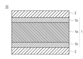
- FIG. 1 It is the fragmentary sectional view which represented typically the structural example from which the lamination
- 10 indicates a medical device, 1a indicates a base layer core, 1b indicates a base surface layer, 1 indicates a base layer, and 2 indicates a lubricating layer, respectively.
- a method of manufacturing a medical device is a method of manufacturing a medical device including a base material layer and a lubricating layer carried on at least a part of the base material layer, and having an epoxy group.
- a block copolymer having a structural unit (A) derived from a reactive monomer and a structural unit (B) derived from a hydrophilic monomer, an alkyl ammonium salt having 8 to 24 carbon atoms, and a solvent Applying and washing a solution containing the above on the substrate layer.
- ADVANTAGE OF THE INVENTION According to this invention, the manufacturing method which has a lubricating layer (coating layer) which exhibits the outstanding durability (especially sliding durability) can be manufactured.
- the structural unit (A) derived from the reactive monomer which has an epoxy group is also only called “the structural unit derived from a reactive monomer” or a “structural unit (A).”
- a structural unit (B) derived from a hydrophilic monomer is also simply referred to as a “structural unit derived from a hydrophilic monomer” or a “structural unit (B)”.
- a block copolymer having a structural unit derived from a reactive monomer and a structural unit derived from a hydrophilic monomer is simply referred to as a “block copolymer” and an alkyl ammonium salt having 8 or more and 24 or less carbon atoms. Also simply referred to as "alkyl ammonium salts”.
- the method for producing a medical device according to the present invention includes a block copolymer having a structural unit derived from a reactive monomer and a structural unit derived from a hydrophilic monomer, an alkyl ammonium salt having a specific carbon number, and a solvent.
- the solution is applied onto the substrate layer and washed.
- the medical device manufactured by the method of this invention can exhibit outstanding durability (surface lubrication maintenance property, sliding durability).
- the mechanism by which the medical device obtained by the manufacturing method according to the present invention can exhibit excellent durability is considered as follows.
- the present invention is not limited to the following estimation.
- a block copolymer having a structural unit (A) derived from a reactive monomer having an epoxy group and a structural unit (B) derived from a hydrophilic monomer is coated on a substrate layer.
- a lubricating layer is formed on a base material layer.
- the block copolymer that forms the lubricating layer exhibits swelling properties when in contact with body fluids or aqueous solvents, thus providing the medical device with lubricity (surface lubricity) and friction with lumen walls such as blood vessel walls.
- the block copolymer forming the lubricating layer forms a network structure (network) by crosslinking or polymerizing the epoxy group contained in the structural unit (A) as a crosslinking point. Conceivable.
- the block copolymer is plasticized by the addition of an alkyl ammonium salt having 8 to 24 carbon atoms, and the blocks having similar properties are aggregated to form a network-like structure by polymerizing. It is thought that it will be crosslinked by subsequent heat treatment to form a network structure (network).
- the alkyl ammonium salt having 8 to 24 carbon atoms contained in the block copolymer solution is crosslinked or polymerized (the formation of a network by a plurality of crosslinks or a network by aggregation) To promote the formation).
- the network structure (network) in the lubricating layer can be formed at a higher density, a strong covering layer (lubricating layer) is formed, and the strong covering layer can be maintained well even after sliding, resulting in high lubrication. It is presumed that the property (surface lubricity) can be maintained for a longer period of time (that is, excellent surface lubricity can be maintained, and sliding durability can be improved).
- crosslinking or polymerization of a block copolymer is also simply referred to as "crosslinking or polymerization of a block copolymer".
- the functional group present on the surface of the base material layer may react with the epoxy group contained in the structural unit (A) to be bonded.
- such reaction is also promoted by the alkyl ammonium salt having 8 or more and 24 or less carbon atoms, and the epoxy group is also bonded (immobilized) to the substrate layer to suppress peeling from the substrate layer. It can be prevented.
- a medical device having excellent durability can be obtained.
- X to Y indicating a range includes X and Y, and means “X or more and Y or less”. Unless otherwise specified, measurements of operations and physical properties etc. are conducted under the conditions of room temperature (20 to 25 ° C.) / Relative humidity 40 to 50% RH.
- the method for producing a medical device comprises a block copolymer having a structural unit (A) derived from a reactive monomer having an epoxy group and a structural unit (B) derived from a hydrophilic monomer, and 8 or more Applying a solution containing an alkyl ammonium salt having 24 or less carbon atoms and a solvent on a substrate layer ((I) solution application step, coating layer forming step), and washing ((II) washing step )including.
- drying and / or heat treatment may be further performed between the steps (I) and (II) ((I ') drying and / or heat treatment step).
- a solution containing a specific alkyl ammonium salt together with the block copolymer, a medical device having a lubricating layer (coating layer) exhibiting excellent durability can be obtained.
- (I) Solution application process (application layer formation process)
- a solution containing the above block copolymer, the above alkyl ammonium salt and a solvent (herein, also simply referred to as “block copolymer solution” or “coating solution”) Is applied onto the substrate layer ((I) solution application step, application layer formation step).
- the solution application step is performed for the purpose of supporting (or coating) a lubricating layer containing a block copolymer on at least a part of the surface of the base layer.
- “Supported” means a state in which the lubricating layer is immobilized so as not to be easily released from the surface of the base layer, and it is only in a form in which the entire surface of the base layer is completely covered by the lubricating layer. In addition, it also includes a form in which only a part of the substrate surface is covered by the lubricating layer, that is, a form in which the lubricating layer adheres to only a part of the substrate surface. Therefore, the method of applying the solution is not particularly limited except that a solution containing the block copolymer having the above-mentioned structural unit (A) and the structural unit (B), the above alkyl ammonium salt, and a solvent is used. It can be applied in the same manner as in the known method or by modifying it appropriately.
- the block copolymer and the alkyl ammonium salt are dissolved in a solvent to prepare a solution (coating solution), and the solution (coating solution) is coated on a substrate and coated. Form a layer.
- the block copolymer forms a lubricating layer supported on at least a part of the base layer. That is, in the medical device obtained by the method according to the present invention, the lubricating layer contains a block copolymer.
- the block copolymer in the present invention has a structural unit (A) derived from a reactive monomer having an epoxy group and a structural unit (B) derived from a hydrophilic monomer.
- the reactive monomer having an epoxy group constituting the block copolymer has an epoxy group as a reactive group.
- the block copolymers are crosslinked or polymerized via an epoxy group to form a network structure.
- the addition of the alkyl ammonium salt according to the present invention promotes crosslinking or polymerization of the block copolymer, thereby improving the strength of the lubricating layer.
- the alkyl ammonium salt according to the present invention not only promotes crosslinking of the epoxy group, but also plasticizes the block copolymer to promote aggregation of blocks having similar properties to each other.
- the medical device obtained by the method according to the present invention is excellent in sliding durability and can maintain its shape well even after sliding.
- the lubricating layer can be strongly bonded (fixed) to the base material layer via an epoxy group, and peeling from the base material layer can be suppressed or prevented. Therefore, also from such a viewpoint, the medical device obtained by the method according to the present invention further improves the sliding durability.
- the structural unit (A) which comprises a block copolymer can be confirmed by a well-known method, in this specification, the loss
- the specific ATR-IR measurement conditions can be those described in the examples.
- the reactive monomer constituting the block copolymer is not particularly limited as long as it has an epoxy group, and known compounds can be used.
- reactive monomers having an epoxy group are glycidyl acrylate, glycidyl methacrylate (GMA), 3,4-epoxycyclohexyl methyl acrylate, since the cross-linking or polymerization of the block copolymer can be easily controlled. It is preferable to include at least one selected from the group consisting of 3,4-epoxycyclohexylmethyl methacrylate, ⁇ -methyl glycidyl methacrylate, and allyl glycidyl ether.
- glycidyl (meth) acrylate is preferable in consideration of the improvement in the ease of formation of the network structure, the ease of production, and the like.
- (meth) acrylate includes both acrylate and methacrylate.
- the above reactive monomers may be used alone or in combination of two or more. That is, the reactive site derived from the reactive monomer may be a homopolymer type composed of one type of reactive monomer alone, or a copolymer composed of two or more types of the above-mentioned reactive monomers It may be a type.
- part in the case of using 2 or more types may be a block copolymer, and a random copolymer may be sufficient as it.
- the hydrophilic monomer constituting the block copolymer has a swelling property when in contact with a body fluid or an aqueous solvent, and thus imparts lubricity (surface lubricity) to the medical device. Therefore, by introducing the structural unit (B) derived from such a hydrophilic monomer into the block copolymer, the lubricity (surface lubricity) of the medical device is improved, and the medical device is a blood vessel wall or the like. Friction on contact with the lumen wall can be reduced.
- the hydrophilic monomer constituting the block copolymer is not particularly limited as long as it has the above-mentioned characteristics, and known compounds can be used.
- acrylamide and derivatives thereof, vinyl pyrrolidone, acrylic acid and methacrylic acid and derivatives thereof, polyethylene glycol acrylate and derivatives thereof, monomers having a sugar or phospholipid in the side chain, and water-soluble unit amounts such as maleic anhydride The body etc. can be illustrated.
- acrylic acid methacrylic acid, N-methyl acrylamide, N, N-dimethyl acrylamide (DMAA), acrylamide, acryloyl morpholine, N, N-dimethylaminoethyl acrylate, N-vinyl pyrrolidone, 2-methacryloyloxy Ethyl phosphoryl choline, 2-methacryloyloxyethyl-D-glycoside, 2-methacryloyloxyethyl-D-mannoside, vinyl methyl ether, 2-hydroxyethyl (meth) acrylate, 4-hydroxybutyl (meth) acrylate, 2-hydroxypropyl (2-hydroxypropyl (meth) acrylate Meta) acrylate, 2-hydroxybutyl (meth) acrylate, 6-hydroxyhexyl (meth) acrylate, 1,4-cyclohexanedimethanol mono (meth) acrylate, 1-chloro 2-hydroxypropyl (meth) acryl
- the hydrophilic monomer is selected from the group consisting of N, N-dimethyl acrylamide, acrylamide, 2-hydroxyethyl methacrylate, and N-vinyl pyrrolidone. It is preferable to include at least one of Among these, from the viewpoint of excellent lubricity, the hydrophilic monomer is preferably N, N-dimethyl acrylamide.
- the hydrophilic monomers may be used alone or in combination of two or more. That is, the hydrophilic moiety derived from the hydrophilic monomer may be a homopolymer type composed of one hydrophilic monomer alone, or a copolymer composed of two or more of the above hydrophilic monomers It may be a type.
- the form of the hydrophilic moiety in the case of using two or more kinds may be a block copolymer or a random copolymer.
- the block copolymer has the structural unit (A) and the structural unit (B).
- the ratio of the structural unit (A) to the structural unit (B) is not particularly limited as long as the above effects are exhibited.
- the ratio of the structural unit (A) to the structural unit (B) (structural unit (A): structural unit (structural unit (A)) in consideration of good lubricity, lubricity maintenance, strength of the coating layer, bondability with the base layer, etc.
- the molar ratio of B) is preferably 1: 2 to 100, more preferably 1: 2 to 50, still more preferably 1: 5 to 50, 1:10 to 1:30. Is particularly preferred.
- the lubricating layer can exhibit sufficient lubricity by the structural unit (B), and by the structural unit (A), sufficient coating layer strength, bondability with the base layer and durability can be obtained. It can be demonstrated.
- the molar ratio of said structural unit (A): structural unit (B) can be controlled by adjusting the preparation ratio (molar ratio) of each monomer in the manufacturing step of a block copolymer.
- the preparation ratio (molar ratio) of the reactive monomer having an epoxy group to the hydrophilic monomer in the production step of the block copolymer is preferably 1: 2 to 100, 1: 2 More preferably, it is ⁇ 50, further preferably 1: 5 to 50, and particularly preferably 1:10 to 1:30.
- the molar ratio of the structural unit (A) to the structural unit (B) can be confirmed, for example, by performing NMR measurement ( 1 H-NMR measurement, 13 C-NMR measurement, etc.) on the copolymer. .
- the weight average molecular weight of the block copolymer is preferably 10,000 to 10,000,000 from the viewpoint of solubility.
- the weight average molecular weight of the block copolymer is more preferably 100,000 to 10,000,000 in view of the easiness of preparation of the block copolymer solution (coating solution).
- “weight average molecular weight” is a value measured by gel permeation chromatography (GPC) using polystyrene as a standard substance.
- the method for producing the block copolymer is not particularly limited, and for example, it can be produced by applying conventionally known polymerization methods such as living radical polymerization, polymerization using a macro initiator, and polycondensation. .
- the living radical polymerization method or the method of easily controlling the molecular weight and molecular weight distribution of the constituent unit (part) derived from the reactive monomer and the constituent unit (part) derived from the hydrophilic monomer A polymerization method using a macro initiator is preferably used.
- the living radical polymerization method is not particularly limited, and methods described in, for example, JP-A-11-263819, JP-A-2002-145971, JP-A-2006-316169, etc., and atom transfer radical polymerization (ATRP) ) Can be applied similarly or appropriately modified.
- ATRP atom transfer radical polymerization
- the macro initiator for example, after preparing a macro initiator having a reactive site having a reactive functional group and a radical polymerizable group such as a peroxide group, the macro initiator and By polymerizing a monomer for forming a hydrophilic site, a block copolymer having a hydrophilic site and a reactive site can be produced.
- the polymerization of the block copolymer known methods such as bulk polymerization, suspension polymerization, emulsion polymerization, solution polymerization and the like may be used.
- a method in which a reactive monomer and a hydrophilic monomer are copolymerized by stirring and heating together with a polymerization initiator in a polymerization solvent can be used.
- the polymerization initiator is not particularly limited, and known ones may be used.
- the polymerization solvent is not particularly limited, and examples thereof include aliphatic organic solvents such as n-hexane, n-heptane, n-octane, n-decane, cyclohexane, methylcyclohexane and liquid paraffin, tetrahydrofuran, dioxane, etc.
- Ether solvents aromatic organic solvents such as benzene, toluene and xylene, halogen organic solvents such as 1,2-dichloroethane and chlorobenzene, and polar aprotic organic solvents such as N, N-dimethylformamide and dimethyl sulfoxide. It can be used.
- the said solvent can also be used individually or in mixture of 2 or more types.
- the concentration of the monomer in the polymerization solvent is preferably 5 to 90% by mass, more preferably 8 to 80% by mass, and 10 to Particularly preferred is 50% by mass.
- the polymerization conditions are also not particularly limited as long as the above copolymerization proceeds.
- the polymerization temperature is preferably 30 to 150 ° C., more preferably 40 to 100 ° C.
- the polymerization time is preferably 30 minutes to 30 hours, more preferably 3 to 24 hours.
- a chain transfer agent if necessary, a chain transfer agent, a polymerization rate regulator, a surfactant, a water soluble polymer, a water soluble inorganic compound (alkali metal salt, alkali metal hydroxide, polyvalent metal salt And non-reducible alkali metal salt pH buffers etc.), inorganic acids, inorganic acid salts, organic acids and organic acid salts and other additives may be used as appropriate.
- the block copolymer after copolymerization is preferably purified by a general purification method such as reprecipitation method, dialysis method, ultrafiltration method and extraction method.
- alkyl ammonium salt promotes the crosslinking or polymerization of the block copolymer.
- a strong lubricating layer can be formed, and excellent durability (sliding durability) can be obtained.
- the promotion of the crosslinking or polymerization of the block copolymer as described above can also be caused by the addition of a strong acid, but the inventor added that when the strong acid is added, the above crosslinking in the block copolymer solution (coating solution) Moreover, as a result of rapid progress of the polymerization, it was found that the viscosity of the coating solution becomes high, and it becomes difficult to apply uniformly. On the other hand, since the alkyl ammonium salt according to the present invention moderately promotes the crosslinking or polymerization of the block copolymer, the coating by crosslinking or polymerization of the block copolymer in the coating solution as described above It is possible to suppress the increase in viscosity of the liquid.
- the coating solution can be uniformly applied by using the alkyl ammonium salt.
- a strong acid it is necessary to separately prepare a solution of the block copolymer and a solution of the strong acid for the above reasons, and apply these in order, but according to the present invention, the lubricating layer At the time of formation of the (coating layer), it is sufficient to apply a liquid containing both of the block copolymer and the alkyl ammonium salt, and there is also an advantage that it is possible to form a lubricating layer (coating layer) by one solution.
- the alkyl ammonium salt in the present invention has 8 or more and 24 or less carbon atoms.
- the number of carbon atoms indicates the total number of carbon atoms contained in the alkyl ammonium cation. If the carbon number of the alkyl ammonium salt is less than 8, the alkyl ammonium salt can not be uniformly dissolved in the block copolymer solution (coating solution), and the solution is uniformly coated on the substrate layer It is difficult. Therefore, sufficient lubricity can not be obtained.
- the alkyl ammonium salt When the carbon number of the alkyl ammonium salt exceeds 24, a uniform solution can be prepared, but the affinity between the alkyl ammonium salt and the lubricating layer (block copolymer) is high, and when the lubricating layer is washed, It is difficult to remove the alkyl ammonium salt. Therefore, the alkyl ammonium salt remains on the lubricating layer, and sufficient lubricity (surface lubricity) can not be obtained. From the viewpoint of forming a lubricating layer having more excellent durability (sliding durability), the alkyl ammonium salt preferably has 12 to 24 carbon atoms, and more preferably 16 to 20 carbon atoms. preferable.
- the alkyl ammonium salt used in the present invention is not particularly limited as long as its cationic moiety has 8 to 24 carbon atoms and at least one alkyl group, and primary to quaternary. It may be any of ammonium salts.
- the alkyl ammonium salt is preferably a quaternary ammonium salt from the viewpoint of easy availability and control of crosslinking or polymerization of the block copolymer.
- the cation moiety of the alkyl ammonium salt may have another substituent other than the alkyl group as long as the carbon number satisfies the above range.
- the other substituent is not particularly limited, and includes, for example, an alkenyl group, an alkynyl group, an aryl group, an acyl group, an alkoxycarbonyl group, an alkoxy group, an aryloxy group, an aryloxy carbonyl group, an acyloxy group and the like. It is also good.
- the cation moiety of the alkyl ammonium salt has no substituent other than the alkyl group, from the viewpoint of easy availability and control of crosslinking or polymerization of the block copolymer. That is, the alkyl ammonium salt is preferably a tetraalkyl ammonium salt.
- the alkyl group contained in the ammonium salt is not particularly limited as long as it satisfies the above carbon number.
- the alkyl ammonium salt has two or more alkyl groups, the alkyl groups may be the same or different.
- the alkyl groups contained in the alkyl ammonium salt each independently have 2 carbon atoms, in view of excellent solubility in the block copolymer solution and easy promotion of crosslinking or polymerization of the block copolymer. It is preferable that it is a linear or branched chain of ⁇ 6, or a cyclic alkyl group having 3 to 6 carbon atoms, and more preferably a linear or branched alkyl group having 2 to 6 carbon atoms, and 2 to 6 carbon atoms It is more preferable that it is a linear alkyl group of the above, and most preferable that it is a linear alkyl group of 4 to 5 carbon atoms.
- alkyl group examples include, for example, ethyl group, n-propyl group, isopropyl group, n-butyl group, isobutyl group, sec-butyl group, tert-butyl group, n-pentyl group, isopentyl group, neopentyl group, n- Examples thereof include linear, branched or cyclic alkyl groups such as hexyl group and cyclohexyl group.
- the alkyl groups in the alkyl ammonium salt are each independently from the viewpoint of excellent solubility in the block copolymer solution and easier control of crosslinking or polymerization of the block copolymer.
- It is preferably selected from the group consisting of ethyl, n-propyl, n-butyl, n-pentyl and n-hexyl, and more preferably n-butyl or n-pentyl.
- the two or more alkyl groups contained in the alkyl ammonium salt are preferably the same, from the viewpoint of easy availability of the alkyl ammonium salt and easier control of crosslinking or polymerization of the block copolymer.
- the alkyl ammonium salt comprises tetraethyl ammonium salt, tetra n-propyl ammonium salt, tetra n-butyl ammonium salt, tetra n-pentyl ammonium salt, and tetra n-hexyl ammonium salt It is preferred to be selected from the group, and more preferred is tetra n-butyl ammonium salt or tetra n-pentyl ammonium salt.
- the anion (counter anion) which forms the alkyl ammonium salt used in the present invention is not particularly limited as long as it can form a salt with the alkyl ammonium cation.
- anions for example, halide ions such as fluoride ion, chloride ion, bromide ion and iodide ion; hydrogen sulfate ion (HSO 4 ⁇ ); sulfate ion (SO 4 2 ⁇ ); nitrate ion NO 3 -); dihydrogen phosphate ion (H 2 PO 4 -), hydrogen phosphate ions (HPO 4 2-), phosphate ion (PO 4 3-); perchlorate ion (ClO 4 -); water oxide ion (OH -); citrate ion, acetic acid ion, malic acid ion, fumarate ion, lactate ion, and a carboxylic acid anion such as glutaric
- the anion of the alkyl ammonium salt is preferably selected from the group consisting of a halide ion, a hydrogen sulfate ion, a perchlorate ion, and a hydroxide ion, since the solubility in the block copolymer solution is excellent.
- the anion of the alkyl ammonium salt is more preferably a halide ion.
- an alkyl ammonium salt having such an anion has relatively weak basicity or is neutral.
- the structural unit (A) contains an epoxy group or a glycidyl ester group
- a block copolymer Hydrolysis of the cross-linked portion of the epoxy group or glycidyl ester group contained therein is less likely to occur. Accordingly, the formed lubricating layer is less susceptible to such hydrolysis, and as a result, the strength of the lubricating layer is improved, and a lubricating layer excellent in durability (sliding durability) can be formed. .
- the anion of the alkyl ammonium salt is preferably selected from the group consisting of chloride ion, bromide ion and iodide ion, and is chloride ion or bromide ion. And particularly preferred.
- An alkyl ammonium salt having a chloride ion or a bromide ion as an anion is particularly weak in basicity, and therefore does not cause hydrolysis of the block copolymer, and aggregation of blocks having epoxy groups or similar properties. Can promote the formation of a more durable lubricating layer.
- alkyl ammonium salt As mentioned above, as an alkyl ammonium salt suitably used in this invention, it is preferable in it being following formula (1):
- R 1 to R 4 each independently represent an ethyl group, an n-propyl group, an n-butyl group, an n-pentyl group or an n-hexyl group, and X - represents a halide ion Hydrogen sulfate ion, perchlorate ion or hydroxide ion.
- R 1 to R 4 in the formula (1) represent an ethyl group, an n-propyl group, an n-butyl group, an n-pentyl group from the viewpoint of forming a lubricating layer having more excellent durability (sliding durability) Or n-hexyl group (wherein a plurality of R 1 to R 4 are the same substituent), and X - is a halide ion, a hydrogen sulfate ion, a perchlorate ion or a hydroxide ion More preferable.
- R 1 to R 4 are n-butyl group or n-pentyl group (however, plural R 1 to R 4 are the same substituent), X - it is still more preferable to be halide ions, wherein (1), R 1 ⁇ R 4 is n- butyl or n- pentyl group (provided that a plurality of R 1 ⁇ R 4 are the same is a substituent), X - is particularly preferable to be chloride, bromide or iodide, in the formula (1), R 1 ⁇ R 4 is an n- butyl or n- pentyl group (However, a plurality of R 1 to R 4 are the same substituent), X 2 ⁇ is most preferably a chloride ion or a bromide ion.
- the said alkyl ammonium salt may be used individually by 1 type, and may use 2 or more types together.
- a homogeneous solution containing the block copolymer and the alkyl ammonium salt is prepared, and the solution (coating solution) is used as a substrate layer. Apply on top.
- the solvent used to dissolve the block copolymer and the alkyl ammonium salt according to the present invention is not particularly limited as long as it can dissolve the block copolymer and the alkyl ammonium salt according to the present invention.
- water alcohols such as methanol, ethanol, isopropanol and ethylene glycol, ketones such as acetone, methyl ethyl ketone and cyclohexanone, esters such as ethyl acetate, halides such as chloroform, olefins such as hexane, and the like (THF), ethers such as butyl ether, aromatics such as benzene and toluene, amides such as N, N-dimethylformamide (DMF), sulfoxides such as dimethyl sulfoxide, etc.
- alcohols such as methanol, ethanol, isopropanol and ethylene glycol
- ketones such as acetone, methyl ethyl
- the solvent of the solution is ketones such as acetone and amides such as DMF.
- acetone and DMF are particularly preferred.
- the block copolymer solution (coating solution) for forming the lubricating layer may contain other components in addition to the block copolymer, the alkyl ammonium salt, and the solvent.
- the other components are not particularly limited, and for example, when the medical device is intended for insertion into a body cavity or lumen such as a catheter, anticancer agents, immunosuppressants, antibiotics, antirheumatic drugs, antithrombotic agents, etc.
- Drug HMG-CoA reductase inhibitor, ACE inhibitor, calcium antagonist, antihyperlipidemic drug, integrin inhibitor, antiallergic drug, antioxidant, GPIIb / IIIa antagonist, retinoid, flavonoid, carotenoid, lipid Improvement agents, DNA synthesis inhibitors, tyrosine kinase inhibitors, antiplatelet agents, vascular smooth muscle growth inhibitors, antiinflammatory agents, biomaterials, interferons, and drugs such as NO production promoters (physiologically active substances) etc.
- the addition amount of the other components is not particularly limited, and the amount usually used is applied in the same manner. Ultimately, the addition amounts of the other components are appropriately selected in consideration of the severity of the disease to be applied, the weight of the patient, and the like.
- a block copolymer solution (coating solution) is prepared using the block copolymer, the alkyl ammonium salt and a solvent.
- the above components may be added collectively or separately, stepwise or continuously.
- the mixing method is not particularly limited, and known methods can be used.
- a preferred method of preparing a block copolymer solution (coating solution) involves sequentially adding a block copolymer and an alkyl ammonium salt to a solvent and stirring in the solvent.
- the concentration of the block copolymer in the block copolymer solution (coating solution) is not particularly limited. From the viewpoint of further improving the coatability and the lubricity and durability of the lubricating layer, the concentration of the block copolymer in the solution (coating solution) is preferably 0.01 to 20% by mass, and 0. The content is more preferably 05 to 15% by mass, and particularly preferably 1 to 10% by mass. If the concentration of the block copolymer is in the above range, the lubricity and durability of the resulting lubricating layer can be sufficiently exhibited.
- the solution contains 0.01 to 20% by mass (more preferably 0.05 to 15% by mass, particularly preferably) of the block copolymer. 1 to 10% by mass).
- a uniform lubricating layer of a desired thickness can be easily obtained by one coating, and the viscosity of the solution falls within an appropriate range, and operability (e.g. ease of coating), production efficiency It is preferable in point. However, if it is a range which does not affect the effect of the present invention even if it deviates from the above-mentioned range, it is fully usable.
- the concentration of the alkyl ammonium salt in the block copolymer solution (coating solution) is also not particularly limited. Alkyl in the solution (coating solution) from the viewpoint that the crosslinking or polymerization of the block copolymer is sufficiently progressed while the progress is not excessively progressed (the crosslinking or polymerization can be appropriately promoted)
- the concentration of the ammonium salt is preferably 0.01 to 20% by mass, more preferably 0.05 to 15% by mass, and particularly preferably 1 to 10% by mass. If the concentration of the alkyl ammonium salt is in the above range, the lubricity and durability of the resulting lubricating layer can be sufficiently exhibited. However, if it is a range which does not affect the effect of the present invention even if it deviates from the above-mentioned range, it is fully usable.
- the mixing ratio of the block copolymer and the alkyl ammonium salt in the block copolymer solution (coating solution) is not particularly limited.
- the solution (coating solution) contains the block copolymer and the alkyl ammonium salt in a ratio of 1: 0.01 to 10 (mass ratio) It is preferable if it is contained, more preferably in a ratio of 1: 0.05 to 5 (mass ratio), particularly preferably in a ratio of 1: 0.05 to 2 (mass ratio), 1: 0.1 to It is most preferable to include at 2 (mass ratio).
- the mass ratio of the block copolymer and the alkyl ammonium salt is in the above range, the lubricity and durability of the resulting lubricating layer can be sufficiently exhibited. Since the alkyl ammonium salt can be sufficiently removed in the washing step described later, the lubricity of the lubricating layer is also improved.
- the base material layer may be made of any material, and examples thereof include metal materials, polymer materials (resin materials), and ceramics.
- the metal material is not particularly limited, and metal materials generally used for medical devices such as catheters, guide wires, and indwelling needles are used.
- various stainless steels such as SUS304, SUS314, SUS316, SUS316L, SUS420J2 and SUS630, gold, platinum, silver, copper, nickel, cobalt, titanium, iron, aluminum, tin or nickel-titanium alloy, nickel-cobalt
- Various alloys such as alloys, cobalt-chromium alloys, zinc-tungsten alloys and the like can be mentioned. These may be used alone or in combination of two or more.
- a metal material most suitable as a base material layer of a catheter, a guide wire, an indwelling needle, etc., which is used, may be appropriately selected.
- the polymer material (resin material or elastomer material) is not particularly limited, and is generally used for medical devices such as catheters, introducers, guide wires, indwelling needles, etc. Used polymeric materials are used.
- polyamide resin polyamide resin
- polyolefin resin such as polyethylene resin and polypropylene resin
- modified polyolefin resin such as polyethylene resin and polypropylene resin
- cyclic polyolefin resin epoxy resin, polyurethane resin, diallyl phthalate resin (allyl resin), polycarbonate resin, fluorocarbon resin, amino resin (urea Resin, melamine resin, benzoguanamine resin)
- polyester resin such as polyethylene terephthalate resin, polybutylene terephthalate resin, styrene resin, acrylic resin, polyacetal resin, vinyl acetate resin, phenol resin, vinyl chloride resin, silicone resin (silicon resin), poly Ether resin, polyimide resin, etc. are mentioned.
- thermoplastic elastomers such as polyurethane elastomers, polyester elastomers and polyamide elastomers can also be used as the material of the base layer.
- polymer materials may be used alone or as a mixture of two or more or a copolymer of two or more monomers constituting any of the above resins or elastomers.
- polymer material polyethylene resin, polyurethane resin, polyethylene terephthalate resin, polyamide resin, and polyamide elastomer are preferable, and polyamide resin and polyamide elastomer are more preferable.
- the carboxy group or amino group as an end group contained in the polyamide resin or the polyamide elastomer can crosslink with the epoxy group in the block copolymer.
- these polymer materials are relatively soft and the block copolymer constituting the lubricating layer is easily impregnated. Therefore, the bondability between the polymer material (in particular, the polyamide resin and the polyamide elastomer) and the block copolymer can be enhanced, and a lubricant layer having more excellent durability can be formed.
- a polymer material most suitable as a base material layer of a catheter, a guide wire, an indwelling needle, etc., which is used, may be appropriately selected.
- the method for producing a medical device according to the present invention is, as described later, the application of a block copolymer solution (coating solution) and, even when maintained at a relatively low temperature, crosslinking of the block copolymer or As the polymerization progresses, a lubricating layer having excellent durability can be formed. In other words, the effect that the temperature at which the lubricating layer is fixed on the base layer can be lowered is also exhibited. Therefore, in the method for producing a medical device according to the present invention, a polymer material (resin material or elastomer material) is suitably used as a constituent material of the base material layer.
- the lubricating layer can be fixed at a low temperature, deformation and plasticization of the base material layer are suppressed even if the base material layer contains a polymer material which is easily deformed or plasticized by heat, and dimensional stability Improve.
- the shape of the said base material layer is not restrict
- the method for applying (coating) the block copolymer solution (coating solution) on the surface of the substrate layer is not particularly limited, and application, printing method, immersion method (dipping method, dip coating method), spraying method (spray method) Methods known in the art, such as spin coating method, mixed solution impregnation sponge coating method, bar coating method, die coating method, reverse coating method, comma coating method, gravure coating method, doctor knife method, etc., can be applied. Among these, it is preferable to use a dipping method (dipping method, dip coating method).
- the base material layer When the lubricating layer is formed on a thin and narrow inner surface such as a catheter, a guide wire, an injection needle or the like, the base material layer may be immersed in a coating solution to decompress the inside of the system to cause degassing. By degassing under reduced pressure, the solution can rapidly penetrate the narrow and narrow inner surface to promote the formation of the lubricating layer.
- a lubricating layer when forming a lubricating layer in a part of base material layer, only a part of base material layer is immersed in a coating liquid, and a coating liquid is coated on a part of base material layer, A lubricating layer can be formed on the desired surface area of the base layer.
- an appropriate member or material capable of attaching / detaching (loading / unloading) the surface part of the substrate layer which does not need to form a lubricating layer beforehand The substrate layer is dipped in a coating solution, and the coating solution is coated on the substrate layer, and then a protective member for the surface portion of the substrate layer that does not need to form a lubricating layer.
- a lubricating layer can be formed on a desired surface portion of the substrate layer.
- a lubricating layer can be formed by appropriately using a conventionally known method.
- another coating method eg, a predetermined surface portion of the medical device, or the like
- a coating method using a coating apparatus such as a spray apparatus, a bar coater, a die coater, a reverse coater, a comma coater, a gravure coater, a spray coater, a doctor knife or the like may be applied.
- a coating apparatus such as a spray apparatus, a bar coater, a die coater, a reverse coater, a comma coater, a gravure coater, a spray coater, a doctor knife or the like may be applied.
- both the outer surface and the inner surface of the cylindrical device need to have a lubricating layer due to the structure of the medical device, both the outer surface and the inner surface can be coated at one time In terms of point, the dipping method is preferably used.
- the coating amount of the block copolymer solution (coating solution) is preferably such that the thickness of the obtained film (lubricating layer) becomes 0.1 to 10 ⁇ m, and the amount such that 0.5 to 5 ⁇ m Is more preferable, and the amount is more preferably 1 to 3 ⁇ m. If the coating amount (the lubricating layer) is such that the thickness is 0.1 ⁇ m or more, the durability of the resulting film (the lubricating layer) can be sufficiently achieved. Further, if the coating amount (the lubricating layer) is 10 ⁇ m or less, the surface of the coating (the lubricating layer) is less likely to stick, and the handling at the time of manufacture becomes easier.
- a block copolymer solution (coating solution) is applied on a base material layer to form a coating layer, and then the solvent is removed. It is preferable to carry out a drying and / or heat treatment step for the purpose of forming a strong lubricating layer.
- drying processing and “heat processing” are not strictly distinguished, but for convenience of explanation, “drying processing” refers to the temperature around the room temperature of the substrate layer to which the coating solution is applied. Holding at (20 to 30 ° C.) or lower is called “drying treatment”, and “heating treatment” is called holding at a temperature near room temperature (20 to 30 ° C.).
- the conditions at the time of drying or heat treatment are not particularly limited as long as the lubricating layer containing the block copolymer can be formed on the base material layer.
- the temperature of the drying or heat treatment is not particularly limited, but preferably 10 to 200 ° C. That is, it is more preferable to maintain the coating layer at 10 to 200 ° C. after the block copolymer solution is applied onto the base layer (after forming the coating layer).
- a strong coating layer lubricant layer
- high lubricity surface lubricity
- the coating layer after applying the block copolymer solution on the base material layer (after forming the coating layer), it is more preferable to maintain the coating layer at 110 ° C. or less, and more preferably 50 to 100 ° C. Most preferably, it is maintained at ° C. By maintaining at such temperature, it is possible to exhibit excellent lubricity and to form a lubricating layer having high durability.
- the temperature by setting the temperature to 110 ° C. or less, excessive crosslinking or polymerization of the block copolymer can be suppressed even when heat treatment is performed for a long time. Therefore, it is possible to suppress a decrease in the swelling property due to the lubricating layer becoming too hard, and it becomes possible to control the lubricity more easily.
- the above temperature may be changed during the drying or heat treatment.
- the temperature is maintained at a relatively low temperature of, for example, 80 ° C. or less, further 25 to 80 ° C.
- the lubricating layer having high durability can be formed. This has the advantage that even polymeric materials that are easily deformed or plasticized by heat can be used as the substrate layer. Therefore, according to the present invention, material selectivity is higher, and medical devices for various applications can be manufactured.
- the time for drying or heat treatment is also not particularly limited, but is preferably 30 minutes to 30 hours, more preferably 1 to 25 hours, and particularly preferably 1 to 10 hours.
- a strong covering layer lubricant layer
- high lubricity surface lubricity
- the alkyl ammonium salt is further subjected to the heat treatment in a state in which the solvent is distilled off (that is, in a state in which the block copolymer and the alkyl ammonium salt are easily in contact) through drying and heat treatment.
- the heat treatment can be performed for a shorter time, and therefore, even a polymer material that is easily deformed or plasticized by heat can be used as the base material layer.
- the conditions (temperature, time, etc.) of drying and heat treatment at this time are not particularly limited either, but from the viewpoint of efficiently producing a medical device, after performing drying treatment maintained at 10 to 30 ° C. for 30 minutes to 5 hours
- heat treatment is performed at 40 to 200 ° C. for 1 to 10 hours.
- the heat treatment is not necessary, and only the drying treatment may be performed. Good.
- the conditions (temperature, time, etc.) of the drying treatment are not particularly limited, but the treatment temperature is preferably 10 to 30 ° C. from the viewpoint of forming a lubricating layer having excellent lubricity and high durability.
- the temperature is more preferably 20 to 25 ° C.
- the treatment time is preferably 5 to 30 hours, more preferably 10 to 25 hours.
- the heat treatment maintained at 50 to 100 ° C. for 2 to 6 hours, or It is preferable to carry out a drying treatment maintained at 20 to 25 ° C. for 10 to 25 hours.
- a strong lubricating layer (coating layer) can be supported on the surface of the base material layer.
- a crosslinking reaction occurs via the epoxy group in the block copolymer in the lubricating layer to form a high-strength lubricating layer that is not easily peeled off from the base material layer. be able to. Therefore, peeling of the lubricating layer from the base material layer can be effectively suppressed / prevented by the drying and / or heat treatment step.
- the pressure condition at the time of drying is not limited at all, and it can be carried out under normal pressure (atmospheric pressure), and may be carried out under pressure or reduced pressure.
- drying or heating means for example, an oven, a vacuum dryer or the like can be used, but in the case of natural drying, a drying means (apparatus) is not particularly required.
- washing step In the method for producing a medical device according to the present invention, the method is provided on the substrate layer after the above (I) solution application step or optionally (I ') drying and / or heat treatment step.
- the lubricating layer is washed ((II) washing step).
- the washing step is performed for the purpose of removing the alkyl ammonium salt contained in the block copolymer solution (coating solution) and imparting excellent lubricity (low friction) to the lubricating layer.
- the washing method is not particularly limited, but may be a method of immersing the coating (lubricant layer) of the block copolymer in a washing solvent, a method of pouring a washing solvent, or a combination thereof.
- the washing solvent used at this time is not particularly limited as long as it does not dissolve the coating (lubricating layer) of the block copolymer and can remove the impurities including the alkyl ammonium salt, but water or hot water can be used. Is preferably used.
- the temperature of the washing water is not particularly limited, but is preferably 20 ° C. to 100 ° C., more preferably 25 to 80 ° C.
- the washing time (the time for bringing the washing solvent into contact with the film) is not particularly limited, but preferably 1 to 60 minutes, more preferably 5 to 30 minutes. According to the above conditions, the alkyl ammonium salt can be sufficiently removed. As a result, the lubricating layer formed on the base material layer can exhibit excellent lubricity.
- a drying step may be further performed.
- the drying method and the drying conditions are not particularly limited, and conventionally known methods can be used.
- the lubricating layer is a base layer by applying a solution (coating liquid) containing a block copolymer and an alkyl ammonium salt forming the lubricating layer on the base layer. It has the configuration carried on it. At this time, in order to improve the lubricity, the smaller the amount of the alkyl ammonium salt contained in the lubricating layer, the better, but it can not be completely removed and may remain. In such a case, it is determined that the medical device was manufactured by the method according to the present invention. Specifically, it is confirmed by detecting the alkyl ammonium salt by the following analysis method.
- the alkyl ammonium salt contained in the lubricating layer after the washing step is preferably 50 ⁇ g / cm 2 or less per unit area, and is 5 ⁇ g / cm 2 or less And more preferred.
- the concentration is preferably 50 ⁇ g / cm 2 or less, the lubricating layer can exhibit excellent lubricity.
- the lower limit thereof is not particularly limited and is preferably as low as possible, but it is 1 ⁇ g / cm 2 or more in consideration of the substantial removal efficiency of the alkyl ammonium salt and the practical lubricity of the lubricating layer.
- the content of the above-mentioned alkyl ammonium salt “per unit area” means the alkyl ammonium salt contained per unit area (1 cm 2 ) of the lubricating layer, and the mass of the alkyl ammonium salt measured by the following method Let ( ⁇ g) be the value obtained by dividing the area of the lubricating layer (cm 2 ).
- the lubricating layer (medical device provided with the lubricating layer) is immersed in water and kept at 70 ° C. for 24 hours. Then, LC-MS measurement is performed on the obtained extract (water) under the following conditions.
- LC / MS measurement conditions >> LC / MS Equipment: Waters 2695 / Quattro micro API (LC) LC model: Waters 2695 Column: Waters X Bridge Amide 2.1 mm ⁇ 150 mm, 3.5 ⁇ m Mobile phase: 20 mmol / L ammonium formate solution (pH 3.2) / acetonitrile (1: 9 (volume ratio)) Flow rate: 0.2mL / min Column temperature: 40 ° C (MS) MS model: Waters Quattro micro API Ionization method: ESI-Positive.
- ⁇ Medical device> Excellent durability can be obtained by passing through the (I) solution application step (coating layer formation step), (II) washing step and optionally (I ') drying and / or heat treatment step described above.
- a medical device having a lubricating layer (coating layer) to be exerted can be manufactured.
- the epoxy group is easily crosslinked by crosslinking the epoxy group. No, it is possible to form a strong lubricating layer.
- the medical device obtained by the method according to the present invention can exhibit excellent lubricity and lubricity maintenance since a lubricant layer of a block copolymer is formed on the surface.
- FIG. 1 is a partial cross-sectional view schematically showing the laminated structure of the surface of a representative embodiment of a medical device (also abbreviated as “medical device” in the present specification) manufactured by the method according to the present invention. is there.
- FIG. 2 is the fragmentary sectional view which represented typically the structural example from which the laminated structure of the surface differs as an application example of this embodiment.
- symbol in FIG. 1 and FIG. 2 represents the following, respectively.
- 1 is a substrate layer; 1a is a substrate layer core portion; 1b is a substrate surface layer; 2 is a lubricant layer; and 10 is a method according to the present invention
- the base material layer 1 and at least a part of the base material layer 1 are provided (in FIG. And a lubricating layer 2 containing a block copolymer (shown in the example shown on the entire surface (entire surface)).
- a lubricating layer 2 containing a block copolymer shown in the example shown on the entire surface (entire surface)
- the present invention is not limited to the above embodiment, and an embodiment formed on one side of the base material layer 1; It may be any form such as a form formed on a part of one side or both sides of the material layer 1.
- the base material layer used in the present embodiment may be composed of any material, and the material is not particularly limited.
- examples of the material constituting the base material layer 1 include metal materials, polymer materials, and ceramics.
- the specific example of the material which comprises the said base material layer 1 is as having described in ⁇ application
- the entire base layer 1 may be made of any of the above-described materials.
- the base material layer 1 may be a multilayer structure formed by laminating different materials in multiple layers, or a structure in which members formed of different materials are joined to each other for each part of the medical device.
- the surface of the base layer core portion 1 a made of any of the above materials is coated with any of the other above materials by an appropriate method to form the base surface layer 1 b. It may have a constructed structure.
- a metal material is coated on the surface of the base layer core portion 1a formed of a resin material or the like by a suitable method (a conventionally known method such as plating, metal deposition, sputtering).
- the surface layer 1b is formed; on the surface of the base layer core portion 1a formed of a hard reinforcing material such as a metal material or a ceramic material, a polymeric material that is softer than the reinforcing material such as a metal material
- the reinforcing material and the polymer material are composited by an appropriate method (dipping, dipping, spraying, coating, printing, etc.).
- the substrate surface layer 1b is formed.
- the base layer core portion 1a may be a multilayer structure in which different materials are laminated in multiple layers, or a structure in which members formed of different materials are joined together for each part of the medical device.
- another middle layer (not shown) may be formed between the base layer core portion 1a and the base surface layer 1b.
- a multilayer structure in which different materials are laminated in multiple layers with respect to the base material surface layer 1b, or a structure in which members formed of different materials are connected to each other for each part of the medical device may be used.
- the lubricating layer is supported on at least a part of the base layer 1.
- the lubricating layer 2 is carried on at least a part of the surface of the base layer 1 in medical devices such as catheters, guide wires, indwelling needles, etc., which are intended to be used. It is not necessary for all surfaces (entire surface) to have lubricity when wet, but only a surface portion (some or all) that is required to have lubricity when wet. Is only required to be carried. For this reason, as described above, the lubricating layer is formed so as to cover the entire both sides of the base layer as shown in FIGS.
- Form to be formed Form to be formed to cover a part of both sides of the substrate layer in the same or different form; Form to be formed to cover a part of one side of the substrate layer and the like.
- the medical device manufactured by the method of the present invention is a device used in contact with body fluid, blood and the like, and the surface has lubricity in aqueous fluid such as body fluid and physiological saline to improve operability. And tissue mucosal damage can be reduced.
- aqueous fluid such as body fluid and physiological saline
- tissue mucosal damage can be reduced.
- catheters used in blood vessels, guide wires, indwelling needles and the like can be mentioned, but the following medical devices are also shown.
- C Catheters inserted or indwelled in the urethra or urinary tract, such as catheters and balloons for urethral catheters, urinary catheters, and urethral balloon catheters.
- E Catheters inserted or indwelled in blood vessels such as indwelling needles, IVH catheters, thermodilution catheters, catheters for angiography, catheters for blood vessel dilatation and dilators or introducers, or catheters for these catheters Guide wire, stylet etc.
- Synthesis Example 1 Synthesis of Block Copolymer (1) The following reaction was carried out to produce a block copolymer (1).
- the block copolymer (1) thus obtained was analyzed by NMR and ATR-IR to confirm that an epoxy group was present in the molecule. Moreover, the weight average molecular weight (Mw) of the block copolymer (1) measured by gel permeation chromatography (GPC, in terms of polystyrene) was about 1.5 million.
- Example 1 The block copolymer (1) obtained in the above Synthesis Example 1 was dissolved in N, N-dimethylformamide (DMF) to a concentration of 6% by mass, and tetraethylammonium bromide (Tokyo Chemical Industry Co., Ltd.) was added thereto. An amount (mass ratio) of 0.5 times that of the block copolymer (1) was added and dissolved to prepare a mixed solution.
- DMF N, N-dimethylformamide
- tetraethylammonium bromide Tokyo Chemical Industry Co., Ltd.
- the surface of the coated tube (1) was analyzed by ATR-IR. As a result, the peak of the epoxy group became smaller, and the reaction of the epoxy group was confirmed. Moreover, the peak of tetraethyl ammonium bromide was not confirmed.
- ATR-IR analysis conditions >> Device: PerkinElmer Fourier Transform Infrared Spectrophotometer Spectrum 100 Measurement mode: ATR method Detector: ZnSe Resolution: 4 cm -1 Measurement range: 4000 to 650 cm -1 Integration count: 4 times.
- Example 2 A coated tube (2) was produced in the same manner as in Example 1 except that tetrapropylammonium bromide (Tokyo Kasei Kogyo Co., Ltd.) was used instead of tetraethylammonium bromide.
- tetrapropylammonium bromide Tokyo Kasei Kogyo Co., Ltd.
- the surface of the coated tube (2) was analyzed by ATR-IR. As a result, the peak of the epoxy group became smaller, and the reaction of the epoxy group was confirmed. Moreover, the peak of tetrapropyl ammonium bromide was not confirmed.
- Example 3 A coated tube (3) was produced in the same manner as in Example 1 except that tetrabutylammonium bromide (Tokyo Kasei Kogyo Co., Ltd.) was used instead of tetraethylammonium bromide.
- tetrabutylammonium bromide Tokyo Kasei Kogyo Co., Ltd.
- the surface of the coated tube (3) was analyzed by ATR-IR. As a result, the peak of the epoxy group became smaller, and the reaction of the epoxy group was confirmed. Moreover, the peak of tetrabutylammonium bromide was not confirmed.
- Example 4 A coated tube (4) was produced in the same manner as in Example 1 except that tetrapentylammonium bromide (Tokyo Kasei Kogyo Co., Ltd.) was used instead of tetraethylammonium bromide.
- tetrapentylammonium bromide Tokyo Kasei Kogyo Co., Ltd.
- the surface of the coated tube (4) was analyzed by ATR-IR, and as a result, the peak of the epoxy group became smaller, and the reaction of the epoxy group was confirmed. Moreover, the peak of tetrapentyl ammonium bromide was not confirmed.
- Example 5 A coated tube (5) was produced in the same manner as in Example 1 except that tetrahexylammonium bromide (Tokyo Kasei Kogyo Co., Ltd.) was used instead of tetraethylammonium bromide.
- tetrahexylammonium bromide Tokyo Kasei Kogyo Co., Ltd.
- the surface of the coated tube (5) was analyzed by ATR-IR. As a result, the peak of the epoxy group became smaller, and the reaction of the epoxy group was confirmed. Moreover, the peak of tetrahexyl ammonium bromide was not confirmed.
- Example 6 Example 1 except that a tube made of tetrabutylammonium fluoride (Aldrich, tetrahydrofuran solution) instead of tetraethylammonium bromide, and polyethylene (Novatec (registered trademark) HB 530 manufactured by Japan Polyethylene Corporation) instead of polyamide elastomer was used. A coated tube (6) was produced in the same manner as in.
- the surface of the coated tube (6) was analyzed by ATR-IR. As a result, the peak of the epoxy group became smaller, and the reaction of the epoxy group was confirmed. Moreover, the peak of tetrabutyl ammonium fluoride was not confirmed.
- Example 7 A coated tube (7) was produced in the same manner as in Example 6, except that tetrabutylammonium chloride (Tokyo Chemical Industry Co., Ltd.) was used instead of tetrabutylammonium fluoride.
- tetrabutylammonium chloride Tokyo Chemical Industry Co., Ltd.
- the surface of the coated tube (7) was analyzed by ATR-IR. As a result, the peak of the epoxy group became smaller, and the reaction of the epoxy group was confirmed. Moreover, the peak of tetrabutyl ammonium chloride was not confirmed.
- Example 8 A coated tube (8) was produced in the same manner as in Example 6, except that tetrabutylammonium bromide (Tokyo Kasei Kogyo Co., Ltd.) was used instead of tetrabutylammonium fluoride.
- tetrabutylammonium bromide Tokyo Kasei Kogyo Co., Ltd.
- the surface of the coated tube (8) was analyzed by ATR-IR. As a result, the peak of the epoxy group became smaller, and the reaction of the epoxy group was confirmed. Moreover, the peak of tetrabutylammonium bromide was not confirmed.
- tetrabutylammonium bromide remaining in the coated tube (8) was a small amount of 5 ⁇ g / cm 2 per unit area.
- the conditions for the LC-MS measurement are as described in the section "(II) Washing step" above.
- Example 9 A coated tube (9) was produced in the same manner as in Example 6, except that tetrabutylammonium iodide (Tokyo Chemical Industry Co., Ltd.) was used instead of tetrabutylammonium fluoride.
- tetrabutylammonium iodide Tokyo Chemical Industry Co., Ltd.
- the surface of the coated tube (9) was analyzed by ATR-IR, and as a result, the peak of the epoxy group became smaller, and the reaction of the epoxy group was confirmed. Moreover, the peak of tetrabutyl ammonium iodide was not confirmed.
- Example 10 A coated tube (10) was produced in the same manner as in Example 6, except that tetrabutylammonium hydrogen sulfate (Tokyo Chemical Industry Co., Ltd.) was used instead of tetrabutylammonium fluoride.
- tetrabutylammonium hydrogen sulfate Tokyo Chemical Industry Co., Ltd.
- the surface of the coated tube (10) was analyzed by ATR-IR, and as a result, the peak of the epoxy group became smaller, and the reaction of the epoxy group was confirmed. Moreover, the peak of tetrabutyl ammonium hydrogen sulfate was not confirmed.
- Example 11 A coated tube (11) was produced in the same manner as in Example 6, except that tetrabutylammonium perchlorate (Tokyo Chemical Industry Co., Ltd.) was used instead of tetrabutylammonium fluoride.
- tetrabutylammonium perchlorate Tokyo Chemical Industry Co., Ltd.
- the surface of the coated tube (11) was analyzed by ATR-IR. As a result, the peak of the epoxy group became smaller, and the reaction of the epoxy group was confirmed. In addition, no peak of tetrabutylammonium perchlorate was confirmed.
- this coated tube (11) was immersed in physiological saline at 25 ° C. and rubbed with a finger, it was confirmed to be a slippery low-friction surface as compared with an untreated tube.
- Example 12 Using tetrabutylammonium hydroxide (10% isopropyl alcohol solution, Tokyo Chemical Industry Co., Ltd.) instead of tetrabutylammonium fluoride, the amount added is 0.05 times the amount (mass) of the block copolymer (1) A coated tube (12) was produced in the same manner as in Example 6, except that the ratio was changed to (ratio).
- the surface of the coated tube (12) was analyzed by ATR-IR. As a result, the peak of the epoxy group became smaller, and the reaction of the epoxy group was confirmed. Moreover, the peak of tetrabutyl ammonium hydroxide was not confirmed.
- Example 13 The block copolymer (1) obtained in the above Synthesis Example 1 is dissolved in acetone so as to have a concentration of 6% by mass, and tetrabutylammonium bromide (Tokyo Chemical Industry Co., Ltd.) is dissolved in the block copolymer (1). ) was added and dissolved to prepare a mixed solution. Immerse the above-mentioned mixed solution in a tube made of polyamide elastomer (Vestamide (registered trademark) E62-S1 manufactured by Daicel Evonik Co., Ltd.) with an outer diameter of 5 Fr (1.65 mm diameter), and dry it at room temperature (25 ° C) for 1 hour Formed.
- Vestamide registered trademark
- E62-S1 manufactured by Daicel Evonik Co., Ltd.
- tetrabutyl ammonium bromide was eluted and removed from the coating by immersing in water at room temperature for 10 minutes.
- the tube was dried at room temperature to prepare a coated tube (13) having a coating layer (lubricant layer) containing a cross-linked copolymer derived from the block copolymer (1) on the surface.
- the surface of the coated tube (13) was analyzed by ATR-IR. As a result, the peak of the epoxy group became smaller, and the reaction of the epoxy group was confirmed. Moreover, the peak of tetrabutylammonium bromide was not confirmed.
- Example 14 A mixed solution containing a block copolymer (1) and the like is applied and dried, and then the tube is stored in an oven at 50 ° C. for 3 hours to heat treat the coating film as in Example 13.
- the coated tube (14) was produced by the method.
- the surface of the coated tube was analyzed by ATR-IR. As a result, the peak of the epoxy group became smaller, and the reaction of the epoxy group was confirmed. Moreover, the peak of tetrabutylammonium bromide was not confirmed.
- Example 15 A mixed solution containing block copolymer (1) and the like was prepared in the same manner as in Example 3, and the object to which the mixed solution was applied was changed to a SUS314 wire with an outer diameter of 5 Fr (1.65 mm diameter).
- the coated wire (1) was produced by the method similar to Example 3.
- the surface analysis of the coated wire (1) was carried out by ATR-IR. As a result, the peak of the epoxy group became smaller, and the reaction of the epoxy group was confirmed. Moreover, the peak of tetrabutylammonium bromide was not confirmed.
- this coated wire (1) was immersed in physiological saline at 25 ° C. and rubbed with a finger, it was confirmed to be a slippery low-friction surface as compared to the untreated wire.
- Example 16 A mixed solution containing a block copolymer (1) and the like is applied and dried, and then the wire is stored in an oven at 130 ° C. for 1 hour to heat treat the coating film as in Example 15.
- the coated wire (2) was produced by the method.
- This coated wire (2) was carried out by ATR-IR, and as a result, the peak of the epoxy group became smaller, and the reaction of the epoxy group was confirmed. Moreover, the peak of tetrabutylammonium bromide was not confirmed.
- this coated wire (2) was immersed in physiological saline at 25 ° C. and rubbed with a finger, it was confirmed to be a slippery low-friction surface as compared to an untreated wire.
- Comparative Example 2 A comparative coated tube (1) was produced in the same manner as in Example 1 except that tetraoctyl ammonium bromide (Wako Pure Chemical Industries, Ltd.) was used instead of tetraethyl ammonium bromide.
- the surface of the comparative coated tube (1) was analyzed by ATR-IR. As a result, the peak of the epoxy group became smaller, and the reaction of the epoxy group was confirmed. In addition, a peak of tetraoctyl ammonium bromide was observed, and it was confirmed that the ammonium salt could not be removed.
- this comparative coated tube (1) was immersed in physiological saline at 25 ° C. and rubbed with a finger, it did not have a slippery low-friction surface as compared to an untreated tube.
- Comparative Example 3 Comparative coated tube (2) was prepared in the same manner as in Example 6, except that the alkyl ammonium salt was not added when preparing the mixed solution containing the block copolymer (1) obtained in the above Synthesis Example 1. Made.
- this comparative coated tube (2) was immersed in physiological saline at 25 ° C. and rubbed with a finger, it was confirmed to be a slippery low-friction surface as compared with an untreated tube.
- Comparative Example 4 Comparative coated wire (1) was prepared in the same manner as Example 16, except that the alkyl ammonium salt was not added at the time of preparation of the mixed solution containing the block copolymer (1) obtained in Synthesis Example 1 above. Made.
- Comparative Example 5 A mixed solution prepared using pyridine (Tokyo Chemical Industry Co., Ltd.) instead of tetrabutylammonium fluoride is applied and dried, and then the tube is stored in an oven at 80 ° C. for 18 hours to heat treat the coating film.
- a comparative coated tube (3) was produced in the same manner as in Example 6 except for the above.
- this comparative coated tube (3) was immersed in physiological saline at 25 ° C. and rubbed with a finger, it was confirmed to be a slippery low-friction surface as compared with an untreated tube.
Abstract
本発明は、優れた耐久性(特に、摺動耐久性)を発揮する潤滑層(被覆層)を有する医療用具の製造方法を提供する。本発明の医療用具の製造方法は、基材層と、前記基材層の少なくとも一部に担持された潤滑層と、を備える医療用具の製造方法である。本発明の医療用具の製造方法は、エポキシ基を有する反応性単量体由来の構成単位(A)および親水性単量体由来の構成単位(B)を有するブロック共重合体と、8以上24以下の炭素原子を有するアルキルアンモニウム塩と、溶媒とを含む溶液を前記基材層上に塗布し、洗浄することを含む。
Description
本発明は、医療用具の製造方法に関する。
カテーテル、ガイドワイヤ等の生体内に挿入される医療用具は、血管などの組織損傷を低減させ、かつ術者の操作性を向上させるため、優れた潤滑性を示すことが要求される。このため、医療用具の基材層表面に潤滑性を有する親水性高分子を被覆する方法は、開発され実用化されている。一方、このような医療用具は、術者の操作性を保つため、術者の使用時に基材層表面に潤滑性を有する親水性高分子を維持できることも重要である。このため、親水性高分子によるコーティングには、優れた潤滑性のみならず磨耗や擦過等の負荷に対する耐久性も要求される。
このような観点から、特開平8-33704号公報には、水溶性または水膨潤性重合体を、医療用具の基材が膨潤する溶媒に溶解させて重合体溶液を作製し、この重合体溶液に医療用具の基材を浸漬して膨潤させ、さらに基材層表面でこの重合体を架橋または高分子化させることによって、基材層表面に表面潤滑層を形成した医療用具が開示されている。
特開平8-33704号公報に開示された技術によれば、比較的良好な潤滑性を示す表面潤滑層を基材に固定することができる。
特開平8-33704号公報には、水溶性または水膨潤性重合体として、潤滑性を発現する親水性部位とエポキシ基を有する部位とからなるブロック共重合体を用いると好ましいことが開示されている。そして、このようなブロック共重合体を用いる場合、加熱操作によりブロック共重合体のエポキシ基を架橋させ、比較的剥離しにくい表面潤滑層を形成することができる。しかし、良好な潤滑性と優れた耐久性とはトレードオフの関係にあり、良好な潤滑性と優れた耐久性を両立させる技術が求められている。
特に、近年の医療用具の小型化・細径化は著しく、生体内において、より屈曲性が高く、狭い病変部位へと医療用具をアプローチする医療手技が広まりつつある。また、医療手技の複雑化に伴い、医療用具の操作が長時間にわたる場合がある。したがって、複雑な病変部位であってもデバイスの操作性を良好に保つために、従来技術よりもさらにデバイス表面の潤滑維持性(耐久性)を高める技術が要求されている。より具体的には、デバイス表面の摺動を繰り返した場合であっても、高い潤滑性を維持できる、摺動耐久性に優れたデバイスが要求されている。
ゆえに、医療用具の耐久性(特に、摺動耐久性)を向上させ、複雑高度化する医療手技をサポートすることができる技術が求められている。
本発明は、上記事情に鑑みてなされたものであり、優れた耐久性(特に、摺動耐久性)を発揮する潤滑層(被覆層)を有する医療用具の製造方法を提供することを目的とする。
本発明者は、上記の問題を解決すべく、鋭意研究を行った結果、エポキシ基を有する反応性単量体と親水性単量体とのブロック共重合体と共に、特定の炭素数を有するアルキルアンモニウム塩をさらに含む溶液を基材層上に塗布し、洗浄することにより、上記目的を達成できることを知得して、本発明を完成するに至った。
すなわち、上記目的は、基材層と、前記基材層の少なくとも一部に担持された潤滑層と、を備える医療用具の製造方法であって、エポキシ基を有する反応性単量体由来の構成単位(A)および親水性単量体由来の構成単位(B)を有するブロック共重合体と、8以上24以下の炭素原子を有するアルキルアンモニウム塩と、溶媒とを含む溶液を前記基材層上に塗布し、洗浄することを含む、医療用具の製造方法によって達成される。
以下、本発明の実施の形態を説明する。
本発明の一形態に係る医療用具の製造方法は、基材層と、前記基材層の少なくとも一部に担持された潤滑層と、を備える医療用具の製造方法であって、エポキシ基を有する反応性単量体由来の構成単位(A)および親水性単量体由来の構成単位(B)を有するブロック共重合体と、8以上24以下の炭素原子を有するアルキルアンモニウム塩と、溶媒とを含む溶液を前記基材層上に塗布し、洗浄することを含む。本発明によれば、優れた耐久性(特に、摺動耐久性)を発揮する潤滑層(被覆層)を有する医療用具を製造方法できる。
なお、本明細書では、エポキシ基を有する反応性単量体由来の構成単位(A)を、単に「反応性単量体由来の構成単位」または「構成単位(A)」とも称する。同様にして、親水性単量体由来の構成単位(B)を、単に「親水性単量体由来の構成単位」または「構成単位(B)」とも称する。また、反応性単量体由来の構成単位および親水性単量体由来の構成単位を有するブロック共重合体を単に「ブロック共重合体」と、8以上24以下の炭素原子を有するアルキルアンモニウム塩を、単に「アルキルアンモニウム塩」とも称する。
本発明に係る医療用具の製造方法では、反応性単量体由来の構成単位および親水性単量体由来の構成単位を有するブロック共重合体、特定の炭素数を有するアルキルアンモニウム塩および溶媒を含む溶液を基材層上に塗布し、洗浄する。当該構成によって、本発明の方法により製造される医療用具は、優れた耐久性(表面潤滑維持性、摺動耐久性)を発揮できる。本発明に係る製造方法により得られる医療用具が、優れた耐久性を呈することができるメカニズムは、以下のように考えられる。なお、本発明は、下記推定に限定されない。
本発明では、まず、エポキシ基を有する反応性単量体由来の構成単位(A)および親水性単量体由来の構成単位(B)を有するブロック共重合体を基材層上に塗布する。これにより、基材層上に潤滑層が形成される。潤滑層を形成するブロック共重合体は、体液や水性溶媒との接触時に膨潤性を発揮し、ゆえに医療用具に潤滑性(表面潤滑性)を付与して血管壁などの管腔壁との摩擦を低減する。
一方で、潤滑層を形成するブロック共重合体は、溶液として塗布された後、構成単位(A)に含まれるエポキシ基を架橋点として、架橋または高分子化して網目構造(ネットワーク)を形成すると考えられる。また、上記ブロック共重合体は、8以上24以下の炭素原子を有するアルキルアンモニウム塩の添加によって可塑化し、類似の性質を有するブロック同士が凝集することによっても、高分子化して網目様構造を形成し、その後の加熱処理によって架橋して、網目構造(ネットワーク)を形成すると考えられる。このとき、本発明では、ブロック共重合体溶液中に含まれる、8以上24以下の炭素原子を有するアルキルアンモニウム塩が上記架橋または高分子化(複数の架橋によるネットワークの形成や、凝集によるネットワークの形成を含む)を促進すると考えられる。その結果、潤滑層中の網目構造(ネットワーク)をより高密度に形成できるため、強固な被覆層(潤滑層)が形成され、摺動後もその強固な被覆層を良好に維持でき、高い潤滑性(表面潤滑性)をより長期間にわたり維持できる(すなわち、優れた表面潤滑性を維持し、摺動耐久性を向上できる)と推測される。なお、以下において、上記のようなブロック共重合体に含まれるエポキシ基を架橋点とする架橋またはブロック共重合体の高分子化を、単に「ブロック共重合体の架橋または高分子化」とも称することがある。
また、基材層(基材)の種類によっては、基材層表面にある官能基と、構成単位(A)に含まれるエポキシ基とが反応して結合することがある。この場合、8以上24以下の炭素原子を有するアルキルアンモニウム塩により、かような反応もまた促進され、エポキシ基が基材層にも結合(固定化)して基材層からの剥離を抑制・防止することができる。
したがって、本発明に係る医療用具の製造方法によれば、優れた耐久性(表面潤滑維持性、摺動耐久性)を有する医療用具が得られる。
以下、本発明の実施の形態を説明する。なお、本発明は、以下の実施の形態のみには限定されない。また、図面の寸法比率は、説明の都合上誇張されており、実際の比率とは異なる場合がある。
また、本明細書において、範囲を示す「X~Y」はXおよびYを含み、「X以上Y以下」を意味する。また、特記しない限り、操作および物性等の測定は室温(20~25℃)/相対湿度40~50%RHの条件で測定する。
<医療用具の製造方法>
本発明に係る医療用具の製造方法は、エポキシ基を有する反応性単量体由来の構成単位(A)および親水性単量体由来の構成単位(B)を有するブロック共重合体と、8以上24以下の炭素原子を有するアルキルアンモニウム塩と、溶媒とを含む溶液を基材層上に塗布すること((I)溶液塗布工程、塗布層形成工程)、および洗浄すること((II)洗浄工程)を含む。また、必要に応じて、上記工程(I)と(II)との間に、さらに乾燥および/または加熱処理を行ってもよい((I’)乾燥および/または加熱処理工程)。このように、ブロック共重合体と共に特定のアルキルアンモニウム塩を含む溶液を塗布することにより、優れた耐久性を発揮する潤滑層(被覆層)を有する医療用具が得られる。
本発明に係る医療用具の製造方法は、エポキシ基を有する反応性単量体由来の構成単位(A)および親水性単量体由来の構成単位(B)を有するブロック共重合体と、8以上24以下の炭素原子を有するアルキルアンモニウム塩と、溶媒とを含む溶液を基材層上に塗布すること((I)溶液塗布工程、塗布層形成工程)、および洗浄すること((II)洗浄工程)を含む。また、必要に応じて、上記工程(I)と(II)との間に、さらに乾燥および/または加熱処理を行ってもよい((I’)乾燥および/または加熱処理工程)。このように、ブロック共重合体と共に特定のアルキルアンモニウム塩を含む溶液を塗布することにより、優れた耐久性を発揮する潤滑層(被覆層)を有する医療用具が得られる。
(I)溶液塗布工程(塗布層形成工程)
本発明に係る医療用具の製造方法では、まず、上記ブロック共重合体、上記アルキルアンモニウム塩および溶媒を含む溶液(本明細書中、単に「ブロック共重合体溶液」または「コート液」とも称する)を基材層上に塗布する((I)溶液塗布工程、塗布層形成工程)。溶液塗布工程は、基材層表面の少なくとも一部に、ブロック共重合体を含む潤滑層を担持(または被覆)させる目的で行われる。なお、「担持」とは、潤滑層が基材層表面から容易に遊離しない状態に固定化された状態を意味し、基材層の表面全体が潤滑層により完全に覆われている形態のみならず、基材表面の一部のみが潤滑層により覆われている形態、すなわち、基材表面の一部のみに潤滑層が付着した形態をも含むものとする。したがって、溶液を塗布する方法は、上記構成単位(A)および構成単位(B)を有するブロック共重合体と、上記アルキルアンモニウム塩と、溶媒とを含む溶液を使用する以外は特に制限されず、公知の方法と同様にしてあるいはこれを適宜修飾して適用できる。
本発明に係る医療用具の製造方法では、まず、上記ブロック共重合体、上記アルキルアンモニウム塩および溶媒を含む溶液(本明細書中、単に「ブロック共重合体溶液」または「コート液」とも称する)を基材層上に塗布する((I)溶液塗布工程、塗布層形成工程)。溶液塗布工程は、基材層表面の少なくとも一部に、ブロック共重合体を含む潤滑層を担持(または被覆)させる目的で行われる。なお、「担持」とは、潤滑層が基材層表面から容易に遊離しない状態に固定化された状態を意味し、基材層の表面全体が潤滑層により完全に覆われている形態のみならず、基材表面の一部のみが潤滑層により覆われている形態、すなわち、基材表面の一部のみに潤滑層が付着した形態をも含むものとする。したがって、溶液を塗布する方法は、上記構成単位(A)および構成単位(B)を有するブロック共重合体と、上記アルキルアンモニウム塩と、溶媒とを含む溶液を使用する以外は特に制限されず、公知の方法と同様にしてあるいはこれを適宜修飾して適用できる。
溶液塗布工程において、具体的には、上記ブロック共重合体および上記アルキルアンモニウム塩を溶媒に溶解させて溶液(コート液)を調製し、当該溶液(コート液)を基材上にコートして塗布層を形成する。
以下、(I)溶液塗布工程(塗布層形成工程)について、好ましい態様を詳説する。
≪ブロック共重合体溶液(コート液)の調製≫
上記の通り、溶液塗布工程(塗布層形成工程)では、ブロック共重合体、アルキルアンモニウム塩および溶媒を含む溶液を基材層上に塗布するため、まず、ブロック共重合体溶液(コート液)を調製する。
上記の通り、溶液塗布工程(塗布層形成工程)では、ブロック共重合体、アルキルアンモニウム塩および溶媒を含む溶液を基材層上に塗布するため、まず、ブロック共重合体溶液(コート液)を調製する。
(ブロック共重合体)
本発明において、ブロック共重合体は、基材層の少なくとも一部に担持された潤滑層を形成する。すなわち、本発明に係る方法により得られる医療用具において、潤滑層は、ブロック共重合体を含む。
本発明において、ブロック共重合体は、基材層の少なくとも一部に担持された潤滑層を形成する。すなわち、本発明に係る方法により得られる医療用具において、潤滑層は、ブロック共重合体を含む。
本発明におけるブロック共重合体は、エポキシ基を有する反応性単量体由来の構成単位(A)および親水性単量体由来の構成単位(B)を有する。
ブロック共重合体を構成するエポキシ基を有する反応性単量体は、エポキシ基を反応性基として有する。このような反応性単量体由来の構成単位(A)をブロック共重合体中に導入することにより、ブロック共重合体同士がエポキシ基を介して架橋または高分子化して網目構造を形成する。ここで、上述のように、本発明に係るアルキルアンモニウム塩が添加されることにより、ブロック共重合体は、架橋または高分子化が促進されるため、潤滑層の強度を向上できる。具体的には、本発明に係るアルキルアンモニウム塩は、エポキシ基の架橋を促進するだけでなく、ブロック共重合体を可塑化させ、類似の性質を有するブロック同士の凝集を促進することで、ブロック共重合体の高分子化に寄与していると推測される。ゆえに、本発明に係る方法により得られる医療用具は、摺動耐久性に優れ、また、摺動後もその形状を良好に維持できる。また、基材層の種類によっては、エポキシ基を介して潤滑層を基材層に強固に結合(固定化)でき、基材層からの剥離を抑制・防止できる。ゆえに、かような観点からも、本発明に係る方法により得られる医療用具は、摺動耐久性がより向上する。
なお、ブロック共重合体を構成する構成単位(A)による網目構造(ネットワーク)の形成は、公知の方法によって確認できるが、本願明細書では、ATR-IRによるエポキシ基の消失およびエーテル結合の形成によって、上記網目構造(ネットワーク)の形成を確認している。なお、具体的なATR-IRの測定条件は、実施例に記載のものを採用することができる。
ブロック共重合体を構成する反応性単量体は、エポキシ基を有するものであれば特に制限されず、公知の化合物を使用できる。なかでも、ブロック共重合体の架橋または高分子化の制御がしやすいことから、エポキシ基を有する反応性単量体は、グリシジルアクリレート、グリシジルメタクリレート(GMA)、3,4-エポキシシクロヘキシルメチルアクリレート、3,4-エポキシシクロヘキシルメチルメタクリレート、β-メチルグリシジルメタクリレート、およびアリルグリシジルエーテルからなる群から選択される少なくとも一種を含んでいると好ましい。なかでも、網目構造の容易形成性の向上、製造の容易さなどを考慮すると、グリシジル(メタ)アクリレートが好ましい。なお、本明細書中、「(メタ)アクリレート」とは、アクリレートおよびメタクリレートの双方を包含する。
上記反応性単量体は、1種単独で使用してもよいし、2種以上を併用してもよい。すなわち、反応性単量体由来の反応性部位は、1種単独の反応性単量体から構成されるホモポリマー型であっても、あるいは上記反応性単量体2種以上から構成されるコポリマー型であってもよい。なお、2種以上用いる場合の反応性部位の形態は、ブロック共重合体でもよいしランダム共重合体でもよい。
ブロック共重合体を構成する親水性単量体は、体液や水性溶媒との接触時に膨潤性を有し、ゆえに潤滑性(表面潤滑性)を医療用具に付与する。したがって、このような親水性単量体由来の構成単位(B)をブロック共重合体中に導入することにより、医療用具の潤滑性(表面潤滑性)が向上し、医療用具が血管壁などの管腔壁と接触した際の摩擦を低減できる。
ブロック共重合体を構成する親水性単量体は、上記特性を有するものであれば特に制限されず、公知の化合物を使用できる。例えば、アクリルアミドやその誘導体、ビニルピロリドン、アクリル酸やメタクリル酸およびそれらの誘導体、ポリエチレングリコールアクリレートおよびその誘導体、糖やリン脂質を側鎖に有する単量体、無水マレイン酸などの水溶性の単量体などを例示できる。より具体的には、アクリル酸、メタクリル酸、N-メチルアクリルアミド、N,N-ジメチルアクリルアミド(DMAA)、アクリルアミド、アクリロイルモルホリン、N,N-ジメチルアミノエチルアクリレート、N-ビニルピロリドン、2-メタクリロイルオキシエチルホスホリルコリン、2-メタクリロイルオキシエチル-D-グリコシド、2-メタクリロイルオキシエチル-D-マンノシド、ビニルメチルエーテル、2-ヒドロキシエチル(メタ)アクリレート、4-ヒドロキシブチル(メタ)アクリレート、2-ヒドロキシプロピル(メタ)アクリレート、2-ヒドロキシブチル(メタ)アクリレート、6-ヒドロキシヘキシル(メタ)アクリレート、1,4-シクロヘキサンジメタノールモノ(メタ)アクリレート、1-クロロ-2-ヒドロキシプロピル(メタ)アクリレート、ジエチレングリコールモノ(メタ)アクリレート、1,6-ヘキサンジオールモノ(メタ)アクリレート、ペンタエリスリトールトリ(メタ)アクリレート、ジペンタエリスリトールペンタ(メタ)アクリレート、ネオペンチルグリコールモノ(メタ)アクリレート、トリメチロールプロパンジ(メタ)アクリレート、トリメチロールエタンジ(メタ)アクリレート、2-ヒドロキシ-3-フェニルオキシプロピル(メタ)アクリレート、4-ヒドロキシシクロヘキシル(メタ)アクリレート、2-ヒドロキシ-3-フェニルオキシ(メタ)アクリレート、4-ヒドロキシシクロヘキシル(メタ)アクリレート、シクロヘキサンジメタノールモノ(メタ)アクリレート、ポリ(エチレングリコール)メチルエーテルアクリレート、およびポリ(エチレングリコール)メチルエーテルメタクリレートが挙げられる。優れた潤滑性の付与、合成の容易性や操作性の観点から、親水性単量体は、N,N-ジメチルアクリルアミド、アクリルアミド、2-ヒドロキシエチルメタクリレート、およびN-ビニルピロリドンからなる群から選択される少なくとも一種を含むと好ましい。なかでも、潤滑性に優れるという観点から、親水性単量体は、N,N-ジメチルアクリルアミドが好ましい。
上記親水性単量体は、1種単独で使用してもよいし、2種以上を併用してもよい。すなわち、親水性単量体由来の親水性部位は、1種単独の親水性単量体から構成されるホモポリマー型であっても、あるいは上記親水性単量体2種以上から構成されるコポリマー型であってもよい。なお、2種以上用いる場合の親水性部位の形態は、ブロック共重合体でもよいしランダム共重合体でもよい。
ブロック共重合体は、上記構成単位(A)および構成単位(B)を有する。ここで、構成単位(A)と構成単位(B)との比率は、上記効果を奏する限り特に制限されない。良好な潤滑性、潤滑維持性、被覆層の強度、基材層との結合性などを考慮すると、構成単位(A)と構成単位(B)との比率(構成単位(A):構成単位(B)のモル比)は、1:2~100であることが好ましく、1:2~50であることがより好ましく、1:5~50であることがさらに好ましく、1:10~1:30であることが特に好ましい。このような範囲であれば、潤滑層は、構成単位(B)により潤滑性を十分発揮でき、また、構成単位(A)により十分な被覆層強度、基材層との結合性および耐久性を発揮できる。なお、上記構成単位(A):構成単位(B)のモル比は、ブロック共重合体の製造段階において、各単量体の仕込み比(モル比)を調整することにより制御することができる。このとき、ブロック共重合体の製造段階におけるエポキシ基を有する反応性単量体と、親水性単量体との仕込み比率(モル比)は、1:2~100であると好ましく、1:2~50であるとより好ましく、1:5~50であることがさらに好ましく、1:10~1:30であることが特に好ましい。なお、上記構成単位(A):構成単位(B)のモル比は、例えば、共重合体についてNMR測定(1H-NMR測定、13C-NMR測定等)を行うことにより確認することができる。
ブロック共重合体の重量平均分子量は、溶解性の点から、好ましくは10,000~10,000,000である。そして、ブロック共重合体の重量平均分子量は、ブロック共重合体溶液(コート液)の調製のしやすさの点から、より好ましくは100,000~10,000,000である。本明細書中、「重量平均分子量」は、ポリスチレンを標準物質とするゲル浸透クロマトグラフィー(Gel Permeation Chromatography、GPC)により測定した値を採用するものとする。
また、ブロック共重合体の製造方法は、特に制限されず、例えば、リビングラジカル重合法、マクロ開始剤を用いた重合法、重縮合法など、従来公知の重合法を適用して作製可能である。これらのうち、反応性単量体に由来する構成単位(部位)、親水性単量体に由来する構成単位(部位)の分子量および分子量分布のコントロールがしやすいという点で、リビングラジカル重合法またはマクロ開始剤を用いた重合法が好ましく使用される。リビングラジカル重合法としては、特に制限されないが、例えば特開平11-263819号公報、特開2002-145971号公報、特開2006-316169号公報等に記載される方法、ならびに原子移動ラジカル重合(ATRP)法などが、同様にしてあるいは適宜修飾して適用できる。また、マクロ開始剤を用いた重合法では、例えば、反応性官能基を有する反応性部位と、パーオキサイド基等のラジカル重合性基とを有するマクロ開始剤を作製した後、そのマクロ開始剤と親水性部位を形成するための単量体を重合させることで親水性部位と反応性部位とを有するブロック共重合体を作製することができる。
また、ブロック共重合体の重合においては、塊状重合、懸濁重合、乳化重合、溶液重合等の公知の方法が用いられうる。具体的には、ブロック共重合体の製造では、反応性単量体および親水性単量体を重合溶媒中で重合開始剤と共に撹拌・加熱することにより共重合させる方法が使用できる。ここで、重合開始剤は特に制限されず、公知のものを使用すればよい。また、重合溶媒としては、特に制限されないが、例えば、n-ヘキサン、n-へプタン、n-オクタン、n-デカン、シクロヘキサン、メチルシクロヘキサン、流動パラフィン等の脂肪族系有機溶媒、テトラヒドロフラン、ジオキサン等のエーテル系溶媒、ベンゼン、トルエン、キシレン等の芳香族系有機溶媒、1,2-ジクロロエタン、クロロベンゼン等のハロゲン系有機溶媒、N,N-ジメチルホルムアミド、ジメチルスルホキシド等の極性非プロトン性有機溶媒が使用できる。なお、前記溶媒は、単独でもまたは2種以上を混合して用いることもできる。
重合溶媒中の単量体の濃度(親水性単量体および反応性単量体の合計濃度)は、5~90質量%であると好ましく、8~80質量%であるとより好ましく、10~50質量%であると特に好ましい。
上記重合において、重合条件もまた、上記共重合が進行すれば特に制限されない。例えば、重合温度は、好ましくは30~150℃、より好ましくは40~100℃とするのが好ましい。また、重合時間は、好ましくは30分~30時間、より好ましくは3~24時間である。
さらに、共重合の際に、必要に応じて、連鎖移動剤、重合速度調整剤、界面活性剤、水溶性高分子、水溶性無機化合物(アルカリ金属塩、アルカリ金属水酸化物、多価金属塩、および非還元性アルカリ金属塩pH緩衝剤など)、無機酸、無機酸塩、有機酸及び有機酸塩およびその他の添加剤を適宜使用してもよい。
共重合後のブロック共重合体は、再沈澱法、透析法、限外濾過法、抽出法など一般的な精製法により精製することが好ましい。
(アルキルアンモニウム塩)
本発明において、アルキルアンモニウム塩は、上記ブロック共重合体の架橋または高分子化を促進する。これにより、強固な潤滑層を形成することができ、優れた耐久性(摺動耐久性)を得ることができる。
本発明において、アルキルアンモニウム塩は、上記ブロック共重合体の架橋または高分子化を促進する。これにより、強固な潤滑層を形成することができ、優れた耐久性(摺動耐久性)を得ることができる。
上記のようなブロック共重合体の架橋または高分子化の促進は、強酸の添加によっても生じうるが、本発明者は、強酸を添加すると、ブロック共重合体溶液(コート液)中において上記架橋また高分子化が急速に進行する結果、コート液の粘性が高くなり、均一に塗布することが難しくなることを見出した。これに対し、本発明に係るアルキルアンモニウム塩は、ブロック共重合体の架橋または高分子化を緩やかに促進するため、上記のようなコート液中におけるブロック共重合体の架橋または高分子化によるコート液の粘性の上昇を抑制できる。よって、本発明では、アルキルアンモニウム塩を用いることにより、コート液を均一に塗布することができる。また、強酸を用いる場合には、上記の理由により、ブロック共重合体の溶液と、強酸の溶液とを別途に調製し、これらを順に塗布する必要があるが、本発明によれば、潤滑層(塗布層)の形成時、ブロック共重合体およびアルキルアンモニウム塩の双方を含む液を塗布すれば足りるため、一液による潤滑層(塗布層)の形成が可能となるという利点もある。
本発明におけるアルキルアンモニウム塩は、8以上24以下の炭素原子を有する。なお、当該炭素原子の数は、アルキルアンモニウムカチオン中に含まれる炭素原子の数の合計を指す。アルキルアンモニウム塩の炭素数が8未満であると、当該アルキルアンモニウム塩がブロック共重合体溶液(コート液)中に均一に溶解させることができず、当該溶液を均一に基材層上に塗布することが難しい。よって、十分な潤滑性が得られない。また、アルキルアンモニウム塩の炭素数が24を超えると、均一な溶液は調製できるものの、当該アルキルアンモニウム塩と潤滑層(ブロック共重合体)との親和性が高く、当該潤滑層を洗浄した際、当該アルキルアンモニウム塩を除去することが難しい。ゆえに、潤滑層上に当該アルキルアンモニウム塩が残留し、十分な潤滑性(表面潤滑性)が得られない。より優れた耐久性(摺動耐久性)を有する潤滑層を形成するという観点から、アルキルアンモニウム塩は、12以上24以下の炭素原子を有すると好ましく、16以上20以下の炭素原子を有するとより好ましい。
本発明において用いられるアルキルアンモニウム塩は、そのカチオン部分が、8以上24以下の炭素原子を有し、少なくとも一つのアルキル基を有するものであれば、特に制限されず、第一級~第四級アンモニウム塩のいずれであってもよい。入手容易性やブロック共重合体の架橋または高分子化の制御をより行いやすくするという観点から、アルキルアンモニウム塩は、第四級アンモニウム塩であると好ましい。
また、アルキルアンモニウム塩において、アルキルアンモニウム塩のカチオン部分は、炭素数が上記範囲を満たす範囲で、アルキル基以外の他の置換基を有していてもよい。他の置換基としては、特に制限されず、例えば、アルケニル基、アルキニル基、アリール基、アシル基、アルコキシカルボニル基、アルコキシ基、アリールオキシ基、アリールオキシカルボニル基、アシルオキシ基等を有していてもよい。しかしながら、入手容易性やブロック共重合体の架橋または高分子化の制御をより行いやすくするという観点から、アルキルアンモニウム塩のカチオン部分が、アルキル基以外の置換基を有していない形態が好ましい。すなわち、アルキルアンモニウム塩は、テトラアルキルアンモニウム塩であると好ましい。
アンモニウム塩中に含まれるアルキル基は、上記炭素数を満たすものであれば特に制限されない。また、アルキルアンモニウム塩が2以上のアルキル基を有する場合、アルキル基は同じであっても異なっていてもよい。
ブロック共重合体溶液に対する溶解性に優れ、また、ブロック共重合体の架橋または高分子化を促進しやすいという観点から、アルキルアンモニウム塩中に含まれるアルキル基は、それぞれ独立して、炭素数2~6の直鎖もしくは分岐鎖、または炭素数3~6の環状のアルキル基であると好ましく、炭素数2~6の直鎖または分岐鎖のアルキル基であるとより好ましく、炭素数2~6の直鎖のアルキル基であるとさらに好ましく、炭素数4~5の直鎖のアルキル基であると最も好ましい。
上記アルキル基としては、例えば、エチル基、n-プロピル基、イソプロピル基、n-ブチル基、イソブチル基、sec-ブチル基、tert-ブチル基、n-ペンチル基、イソペンチル基、ネオペンチル基、n-ヘキシル基、シクロヘキシル基等の直鎖、分岐鎖または環状のアルキル基が挙げられる。なかでも、ブロック共重合体溶液に対する溶解性に優れ、また、ブロック共重合体の架橋または高分子化の制御をより行いやすくするという観点から、アルキルアンモニウム塩中のアルキル基は、それぞれ独立して、エチル基、n-プロピル基、n-ブチル基、n-ペンチル基およびn-ヘキシル基からなる群から選択されると好ましく、n-ブチル基またはn-ペンチル基であるとより好ましい。
アルキルアンモニウム塩の入手容易性やブロック共重合体の架橋または高分子化の制御をより行いやすくするという観点から、アルキルアンモニウム塩に含まれる2以上のアルキル基は、同じものであると好ましい。
なかでも、上記好ましいアルキル基を考慮すると、アルキルアンモニウム塩は、テトラエチルアンモニウム塩、テトラn-プロピルアンモニウム塩、テトラn-ブチルアンモニウム塩、テトラn-ペンチルアンモニウム塩、およびテトラn-ヘキシルアンモニウム塩からなる群から選択されると好ましく、テトラn-ブチルアンモニウム塩またはテトラn-ペンチルアンモニウム塩であるとより好ましい。
一方、本発明において用いられるアルキルアンモニウム塩を形成するアニオン(カウンターアニオン)は、上記アルキルアンモニウムカチオンと塩を形成できるものであれば、特に制限されない。かようなアニオンとしては、例えば、フッ化物イオン、塩化物イオン、臭化物イオンおよびヨウ化物イオン等のハロゲン化物イオン;硫酸水素イオン(HSO4
-);硫酸イオン(SO4
2-);硝酸イオン(NO3
-);リン酸二水素イオン(H2PO4
-)、リン酸水素イオン(HPO4
2-)、リン酸イオン(PO4
3-);過塩素酸イオン(ClO4
-);水酸化物イオン(OH-);クエン酸イオン、酢酸イオン、リンゴ酸イオン、フマル酸イオン、乳酸イオン、グルタル酸イオンおよびマレイン酸イオン等のカルボン酸系アニオンが挙げられる。ブロック共重合体溶液に対する溶解性に優れることから、アルキルアンモニウム塩のアニオンは、ハロゲン化物イオン、硫酸水素イオン、過塩素酸イオン、および水酸化物イオンからなる群から選択されると好ましい。
さらに、アルキルアンモニウム塩のアニオンは、ハロゲン化物イオンであるとより好ましい。かようなアニオンを有するアルキルアンモニウム塩を用いることにより、潤滑層の耐久性が極めて向上する。かかる理由は、以下のように考えられる。ハロゲン化物イオンをアニオンとするアルキルアンモニウム塩は、塩基性が比較的弱いか、または中性であることから、例えば、構成単位(A)がエポキシ基またはグリシジルエステル基を含む場合、ブロック共重合体中に含まれるエポキシ基の架橋部分またはグリシジルエステル基の加水分解が生じにくい。よって、形成される潤滑層が、かような加水分解の影響を受けにくくなるため、結果として潤滑層の強度が向上し、耐久性(摺動耐久性)に優れる潤滑層を形成することができる。
より耐久性に優れた潤滑層を形成するという観点から、アルキルアンモニウム塩のアニオンは、塩化物イオン、臭化物イオンおよびヨウ化物イオンからなる群から選択されると好ましく、塩化物イオンまたは臭化物イオンであると特に好ましい。塩化物イオンまたは臭化物イオンをアニオンとするアルキルアンモニウム塩は、特に塩基性が弱いことから、ブロック共重合体の加水分解を生じさせず、かつエポキシ基の架橋または類似の性質を有するブロック同士の凝集を促進するため、より耐久性に優れる潤滑層を形成できる。
以上より、本発明において好適に用いられるアルキルアンモニウム塩としては、下記式(1)であると好ましい:
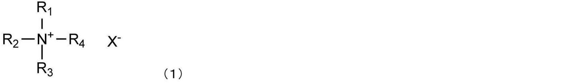
式(1)中、R1~R4は、それぞれ独立して、エチル基、n-プロピル基、n-ブチル基、n-ペンチル基またはn-ヘキシル基であり、X-は、ハロゲン化物イオン、硫酸水素イオン、過塩素酸イオンまたは水酸化物イオンである。
より耐久性(摺動耐久性)に優れる潤滑層を形成するという観点から、式(1)中、R1~R4は、エチル基、n-プロピル基、n-ブチル基、n-ペンチル基またはn-ヘキシル基であり(ただし、複数のR1~R4は、同じ置換基である)、X-は、ハロゲン化物イオン、硫酸水素イオン、過塩素酸イオンまたは水酸化物イオンであるとより好ましい。さらに同様の観点から、式(1)中、R1~R4は、n-ブチル基またはn-ペンチル基であり(ただし、複数のR1~R4は、同じ置換基である)、X-は、ハロゲン化物イオンであるとさらにより好ましく、式(1)中、R1~R4は、n-ブチル基またはn-ペンチル基であり(ただし、複数のR1~R4は、同じ置換基である)、X-は、塩化物イオン、臭化物イオンまたはヨウ化物イオンであると特に好ましく、式(1)中、R1~R4は、n-ブチル基またはn-ペンチル基であり(ただし、複数のR1~R4は、同じ置換基である)、X-は、塩化物イオンまたは臭化物イオンであると最も好ましい。
なお、上記アルキルアンモニウム塩は、1種単独で使用してもよいし、2種以上を併用してもよい。
(溶媒)
本発明では、ブロック共重合体を均一に基材層上に担持させる目的から、上記ブロック共重合体および上記アルキルアンモニウム塩を含む均一な溶液を調製し、当該溶液(コート液)を基材層上に塗布する。
本発明では、ブロック共重合体を均一に基材層上に担持させる目的から、上記ブロック共重合体および上記アルキルアンモニウム塩を含む均一な溶液を調製し、当該溶液(コート液)を基材層上に塗布する。
本発明に係るブロック共重合体およびアルキルアンモニウム塩を溶解するのに使用される溶媒としては、本発明に係るブロック共重合体およびアルキルアンモニウム塩を溶解できるものであれば特に制限されない。具体的には、水、メタノール、エタノール、イソプロパノール、エチレングリコール等のアルコール類、アセトン、メチルエチルケトン、シクロヘキサノン等のケトン類、酢酸エチル等のエステル類、クロロホルム等のハロゲン化物、ヘキサン等のオレフィン類、テトラヒドロフラン(THF)、ブチルエーテル等のエーテル類、ベンゼン、トルエン等の芳香族類、N,N-ジメチルホルムアミド(DMF)等のアミド類、ジメチルスルホキシド等のスルホキシド類などを例示することができるが、これらに何ら制限されるものではない。これらは1種単独で用いてもよいし、2種以上併用してもよい。なかでも、ブロック共重合体およびアルキルアンモニウム塩を均一に溶解でき、溶液の塗布を均一に行えるという観点から、溶液(コート液)の溶媒は、アセトン等のケトン類、およびDMF等のアミド類が好ましく、アセトンおよびDMFが特に好ましい。
(他の成分)
潤滑層を形成するためのブロック共重合体溶液(コート液)は、ブロック共重合体、アルキルアンモニウム塩、溶媒の他、他の成分を含んでいてもよい。他の成分としては、特に制限されず、例えば、医療用具がカテーテルなどの体腔や管腔内への挿入を目的とする場合には、抗癌剤、免疫抑制剤、抗生物質、抗リウマチ薬、抗血栓薬、HMG-CoA還元酵素阻害剤、ACE阻害剤、カルシウム拮抗剤、抗高脂血症薬、インテグリン阻害薬、抗アレルギー剤、抗酸化剤、GPIIb/IIIa拮抗薬、レチノイド、フラボノイド、カロチノイド、脂質改善薬、DNA合成阻害剤、チロシンキナーゼ阻害剤、抗血小板薬、血管平滑筋増殖抑制薬、抗炎症薬、生体由来材料、インターフェロン、およびNO産生促進物質等の薬剤(生理活性物質)などが挙げられる。ここで、他の成分の添加量は、特に制限されず、通常使用される量が同様にして適用される。最終的には、他の成分の添加量は、適用される疾患の重篤度、患者の体重等を考慮して適切に選択される。
潤滑層を形成するためのブロック共重合体溶液(コート液)は、ブロック共重合体、アルキルアンモニウム塩、溶媒の他、他の成分を含んでいてもよい。他の成分としては、特に制限されず、例えば、医療用具がカテーテルなどの体腔や管腔内への挿入を目的とする場合には、抗癌剤、免疫抑制剤、抗生物質、抗リウマチ薬、抗血栓薬、HMG-CoA還元酵素阻害剤、ACE阻害剤、カルシウム拮抗剤、抗高脂血症薬、インテグリン阻害薬、抗アレルギー剤、抗酸化剤、GPIIb/IIIa拮抗薬、レチノイド、フラボノイド、カロチノイド、脂質改善薬、DNA合成阻害剤、チロシンキナーゼ阻害剤、抗血小板薬、血管平滑筋増殖抑制薬、抗炎症薬、生体由来材料、インターフェロン、およびNO産生促進物質等の薬剤(生理活性物質)などが挙げられる。ここで、他の成分の添加量は、特に制限されず、通常使用される量が同様にして適用される。最終的には、他の成分の添加量は、適用される疾患の重篤度、患者の体重等を考慮して適切に選択される。
(ブロック共重合体溶液(コート液)の調製)
上記ブロック共重合体、アルキルアンモニウム塩および溶媒を用いて、ブロック共重合体溶液(コート液)を調製する。上記各成分の添加順、添加方法は特に制限されない。上記各成分を、一括してもしくは別々に、段階的にもしくは連続して加えてもよい。また、混合方法も特に制限されず、公知の方法を用いることができる。好ましいブロック共重合体溶液(コート液)の調製方法としては、溶媒中にブロック共重合体およびアルキルアンモニウム塩を順次添加し、溶媒中で撹拌することを含む。
上記ブロック共重合体、アルキルアンモニウム塩および溶媒を用いて、ブロック共重合体溶液(コート液)を調製する。上記各成分の添加順、添加方法は特に制限されない。上記各成分を、一括してもしくは別々に、段階的にもしくは連続して加えてもよい。また、混合方法も特に制限されず、公知の方法を用いることができる。好ましいブロック共重合体溶液(コート液)の調製方法としては、溶媒中にブロック共重合体およびアルキルアンモニウム塩を順次添加し、溶媒中で撹拌することを含む。
ブロック共重合体溶液(コート液)中のブロック共重合体の濃度は、特に限定されない。塗布性、潤滑層の潤滑性および耐久性をより向上させるという観点からは、当該溶液(コート液)中のブロック共重合体の濃度は、0.01~20質量%であると好ましく、0.05~15質量%であるとより好ましく、1~10質量%であると特に好ましい。ブロック共重合体の濃度が上記範囲であれば、得られる潤滑層の潤滑性、耐久性が十分発揮されうる。すなわち、本発明の好ましい形態によると、溶液(ブロック共重合体溶液、コート液)が、ブロック共重合体を0.01~20質量%(より好ましくは0.05~15質量%、特に好ましくは1~10質量%)含む。また、1回のコーティングで所望の厚みの均一な潤滑層を容易に得ることができ、また、溶液の粘度が適切な範囲内となり、操作性(例えば、コーティングのしやすさ)、生産効率の点で好ましい。但し、上記範囲を外れても、本発明の作用効果に影響を及ぼさない範囲であれば、十分に利用可能である。
ブロック共重合体溶液(コート液)中のアルキルアンモニウム塩の濃度もまた特に限定されない。ブロック共重合体の架橋または高分子化を十分に進行させながらも、一方で、過度に進行させない(架橋または高分子化を適度に促進できる)という観点から、当該溶液(コート液)中のアルキルアンモニウム塩の濃度は、0.01~20質量%であると好ましく、0.05~15質量%であるとより好ましく、1~10質量%であると特に好ましい。アルキルアンモニウム塩の濃度が上記範囲であれば、得られる潤滑層の潤滑性、耐久性が十分発揮されうる。但し、上記範囲を外れても、本発明の作用効果に影響を及ぼさない範囲であれば、十分に利用可能である。
さらに、ブロック共重合体溶液(コート液)中における、ブロック共重合体およびアルキルアンモニウム塩の混合比も特に限定されない。塗布性、潤滑層の潤滑性および耐久性をより向上させるという観点からは、当該溶液(コート液)は、ブロック共重合体およびアルキルアンモニウム塩を、1:0.01~10(質量比)で含んでいると好ましく、1:0.05~5(質量比)で含んでいるとより好ましく、1:0.05~2(質量比)で含んでいると特に好ましく、1:0.1~2(質量比)で含んでいると最も好ましい。ブロック共重合体およびアルキルアンモニウム塩の質量比が上記範囲であれば、得られる潤滑層の潤滑性、耐久性が十分発揮されうる。後述する洗浄工程において、アルキルアンモニウム塩を十分に除けることから、潤滑層の潤滑性も向上する。
≪ブロック共重合体溶液(コート液)の塗布≫
次に、上記の通りブロック共重合体、アルキルアンモニウム塩および溶媒を含む溶液(コート液)を調製した後、当該溶液を基材層上に塗布する。
次に、上記の通りブロック共重合体、アルキルアンモニウム塩および溶媒を含む溶液(コート液)を調製した後、当該溶液を基材層上に塗布する。
基材層は、いずれの材料から構成されてもよいが、例えば、金属材料、高分子材料(樹脂材料)、およびセラミックスなどが挙げられる。
基材層を構成する材料のうち、金属材料としては、特に制限されるものではなく、カテーテル、ガイドワイヤ、留置針等の医療用具に一般的に使用される金属材料が使用される。具体的には、SUS304、SUS314、SUS316、SUS316L、SUS420J2、SUS630などの各種ステンレス鋼、金、白金、銀、銅、ニッケル、コバルト、チタン、鉄、アルミニウム、スズあるいはニッケル-チタン合金、ニッケル-コバルト合金、コバルト-クロム合金、亜鉛-タングステン合金等の各種合金などが挙げられる。これらは1種単独で使用してもよいし、2種以上を併用してもよい。上記金属材料には、使用用途であるカテーテル、ガイドワイヤ、留置針等の基材層として最適な金属材料を適宜選択すればよい。
また、上記基材層を構成する材料のうち、高分子材料(樹脂材料またはエラストマー材料)としては、特に制限されるものではなく、カテーテル、イントロデューサー、ガイドワイヤ、留置針等の医療用具に一般的に使用される高分子材料が使用される。具体的には、ポリアミド樹脂、ポリエチレン樹脂やポリプロピレン樹脂などのポリオレフィン樹脂、変性ポリオレフィン樹脂、環状ポリオレフィン樹脂、エポキシ樹脂、ポリウレタン樹脂、ジアリルフタレート樹脂(アリル樹脂)、ポリカーボネート樹脂、フッ素樹脂、アミノ樹脂(ユリア樹脂、メラミン樹脂、ベンゾグアナミン樹脂)、ポリエチレンテレフタレート樹脂、ポリブチレンテレフタレート樹脂などのポリエステル樹脂、スチロール樹脂、アクリル樹脂、ポリアセタール樹脂、酢酸ビニル樹脂、フェノール樹脂、塩化ビニル樹脂、シリコーン樹脂(ケイ素樹脂)、ポリエーテル樹脂、ポリイミド樹脂などが挙げられる。
また、ポリウレタンエラストマー、ポリエステルエラストマー、ポリアミドエラストマーなどの熱可塑性エラストマーも、基材層の材料として用いることができる。
これらの高分子材料は1種単独で使用してもよいし、2種以上の混合物または上記いずれかの樹脂またはエラストマーを構成する2種以上の単量体の共重合体として使用してもよい。なかでも、高分子材料としては、ポリエチレン樹脂、ポリウレタン樹脂、ポリエチレンテレフタレート樹脂、ポリアミド樹脂、ポリアミドエラストマーが好ましく、ポリアミド樹脂、ポリアミドエラストマーがより好ましい。ポリアミド樹脂やポリアミドエラストマーに含まれる末端基としてのカルボキシ基やアミノ基は、ブロック共重合体中のエポキシ基と架橋反応しうる。また、これらの高分子材料(特にポリアミド樹脂、ポリアミドエラストマー)は、比較的柔らかく、潤滑層を構成するブロック共重合体がしみ込みやすいともいえる。よって、高分子材料(特にポリアミド樹脂、ポリアミドエラストマー)とブロック共重合体との結合性が高まり、より耐久性に優れた潤滑層を形成することができる。上記高分子材料には、使用用途であるカテーテル、ガイドワイヤ、留置針等の基材層として最適な高分子材料を適宜選択すればよい。
本発明に係る医療用具の製造方法は、後述するように、ブロック共重合体溶液(コート液)を塗布した後、比較的低い温度で維持した場合であっても、ブロック共重合体の架橋または高分子化が進行し、耐久性に優れる潤滑層を形成できる。換言すると、潤滑層を基材層上に固定する温度を低くすることができるという効果もまた奏される。したがって、本発明に係る医療用具の製造方法においては、基材層の構成材料として、高分子材料(樹脂材料またはエラストマー材料)が好適に用いられる。本発明によれば、低温で潤滑層を固定できることから、熱により変形または可塑化しやすい高分子材料を基材層に含んでいても、基材層の変形や可塑化が抑制され、寸法安定性が向上する。
また、上記基材層の形状は、特に制限されることはなく、シート状、線状(ワイヤ)、管状など使用態様により適宜選択される。
基材層表面にブロック共重合体溶液(コート液)を塗布(コーティング)する方法は、特に制限されず、塗布・印刷法、浸漬法(ディッピング法、ディップコート法)、噴霧法(スプレー法)、スピンコート法、混合溶液含浸スポンジコート法、バーコート法、ダイコート法、リバースコート法、コンマコート法、グラビアコート法、ドクターナイフ法など、従来公知の方法を適用することができる。これらのうち、浸漬法(ディッピング法、ディップコート法)を用いるのが好ましい。
なお、カテーテル、ガイドワイヤ、注射針等の細く狭い内面に潤滑層を形成させる場合、コート液中に基材層を浸漬して、系内を減圧にして脱泡させてもよい。減圧にして脱泡させることにより、細く狭い内面に素早く溶液を浸透させ、潤滑層の形成を促進できる。
また、基材層の一部にのみ潤滑層を形成させる場合には、基材層の一部のみをコート液中に浸漬して、コート液を基材層の一部にコーティングすることで、基材層の所望の表面部位に、潤滑層を形成することができる。
基材層の一部のみをコート液中に浸漬するのが困難な場合には、予め潤滑層を形成する必要のない基材層の表面部分を着脱(装脱着)可能な適当な部材や材料で保護(被覆等)した上で、基材層をコート液中に浸漬して、コート液を基材層にコーティングした後、潤滑層を形成する必要のない基材層の表面部分の保護部材(材料)を取り外し、その後、加熱処理等により反応させることで、基材層の所望の表面部位に潤滑層を形成することができる。ただし、本発明では、これらの形成法に何ら制限されるものではなく、従来公知の方法を適宜利用して、潤滑層を形成することができる。例えば、基材層の一部のみをコート液中に浸漬するのが困難な場合には、浸漬法に代えて、他のコーティング手法(例えば、医療用具の所定の表面部分に、コート液を、スプレー装置、バーコーター、ダイコーター、リバースコーター、コンマコーター、グラビアコーター、スプレーコーター、ドクターナイフなどの塗布装置を用いて、塗布する方法など)を適用してもよい。なお、医療用具の構造上、円筒状の用具の外表面と内表面の双方が、潤滑層を有する必要があるような場合には、一度に外表面と内表面の双方をコーティングすることができる点で、浸漬法(ディッピング法)が好ましく使用される。
ブロック共重合体溶液(コート液)の塗布量は、得られる被膜(潤滑層)の厚みが0.1~10μmとなるような量であることが好ましく、0.5~5μmとなるような量であることがより好ましく、1~3μmとなるような量であることがさらに好ましい。被膜(潤滑層)の厚みが0.1μm以上となるような塗布量であれば、得られる被膜(潤滑層)の耐久性が十分達成できる。また、被膜(潤滑層)の厚みが10μm以下となるような塗布量であれば、被膜(潤滑層)の表面がべたつきにくくなり、製造時の取扱いがより容易になる。
(I’)乾燥および/または加熱処理工程
本発明に係る医療用具の製造方法では、基材層上にブロック共重合体溶液(コート液)を塗布して塗布層を形成した後、溶媒の除去や、強固な潤滑層を形成する目的で、乾燥および/または加熱処理工程を行うと好ましい。
本発明に係る医療用具の製造方法では、基材層上にブロック共重合体溶液(コート液)を塗布して塗布層を形成した後、溶媒の除去や、強固な潤滑層を形成する目的で、乾燥および/または加熱処理工程を行うと好ましい。
以下、(I’)ブロック共重合体溶液(コート液)の乾燥および/または加熱処理工程について、好ましい態様を詳説する。
上記(I)溶液塗布工程において、基材層上に、ブロック共重合体およびアルキルアンモニウム塩を含む溶液(コート液)を塗布した後、乾燥および/または加熱処理を行うと好ましい。ここで、「乾燥処理」と「加熱処理」とは、厳密に区別されるものではないが、説明の便宜上、「乾燥処理」とは、上記コート液を塗布した基材層を室温付近の温度(20~30℃)以下に保持することを「乾燥処理」といい、「加熱処理」とは、室温付近の温度(20~30℃)を超える温度に保持することを「加熱処理」という。
乾燥または加熱処理時の条件は、基材層上にブロック共重合体を含む潤滑層が形成できる条件であれば、特に制限されない。
乾燥または加熱処理の温度は、特に制限されないが、好ましくは10~200℃である。すなわち、ブロック共重合体溶液を基材層上に塗布した後(塗布層を形成した後)、塗布層を10~200℃で維持するとより好ましい。かような温度で維持することにより、ブロック共重合体の架橋または高分子化が効果的に促進され、強固な被覆層(潤滑層)が形成される。よって、高い潤滑性(表面潤滑性)をより長期間にわたり維持できる。また、かような温度で維持することにより、上記架橋または高分子化が過剰に進行してしまうのを抑制することができる。よって、潤滑層が硬くなりすぎることに起因する膨潤性の低下を抑制でき、結果として、良好な潤滑性(表面潤滑性)を維持できる。
さらに、ブロック共重合体溶液を基材層上に塗布した後(塗布層を形成した後)、塗布層を110℃以下で維持するとより好ましく、25~110℃で維持するとさらに好ましく、50~100℃で維持すると最も好ましい。かような温度で維持することにより、優れた潤滑性を発揮することができ、かつ、高い耐久性を有する潤滑層を形成することができる。特に、110℃以下とすることにより、加熱処理を長時間行っても、ブロック共重合体の過剰な架橋または高分子化を抑制することができる。よって、潤滑層が硬くなりすぎることに起因する膨潤性の低下を抑制でき、潤滑性の制御をより容易に行うことが可能となる。なお、上記温度は、乾燥または加熱処理の途中で変更してもよい。
本発明に係る製造方法では、上記のように、ブロック共重合体溶液(コート液)を塗布した後、例えば80℃以下、さらには25~80℃といった、比較的低い温度で維持した場合であっても、高い耐久性を有する潤滑層を形成できることもまた特徴の一つである。これにより、熱により変形または可塑化しやすい高分子材料であっても、基材層として使用できるという利点がある。したがって、本発明によれば、材料の選択性がより高くなり、多様な用途の医療用具を製造することができる。また、低温で耐久性に優れた潤滑層の形成が可能であるため、医療用具の製造時、エネルギーコスト的な観点からも好ましい。
また、乾燥または加熱処理の時間も特に制限されないが、好ましくは30分~30時間、より好ましくは1~25時間、特に好ましくは1~10時間である。かような時間とすることにより、ブロック共重合体中の架橋または高分子化が効果的に促進され、強固な被覆層(潤滑層)が形成される。よって、高い潤滑性(表面潤滑性)をより長期間にわたり維持できる。また、かような時間とすることにより、上記架橋または高分子化が過剰に進行してしまうのを抑制することができる。よって、潤滑層が硬くなりすぎることに起因する膨潤性の低下を抑制でき、結果として、良好な潤滑性(表面潤滑性)を維持できる。
本工程において、ブロック共重合体の架橋または高分子化を特に効果的に(効率よく)促進させるという観点から、乾燥処理を行った後、さらに加熱処理を行うことが好ましい。このように、乾燥および加熱処理を経ることで、溶媒が留去された状態で(すなわち、ブロック共重合体とアルキルアンモニウム塩とが接触しやすい状態で)さらに加熱処理を行うため、アルキルアンモニウム塩によるブロック共重合体の架橋または高分子化を促進する効果がより向上する。したがって、加熱処理をより短時間とすることができるため、熱により変形または可塑化しやすい高分子材料であっても、基材層として用いることができる。
このときの乾燥および加熱処理の条件(温度、時間等)も特に制限されないが、効率よく医療用具を製造するという観点から、10~30℃で30分~5時間維持する乾燥処理を行った後、40~200℃で1~10時間維持する加熱処理を行うと好ましい。さらに同様の観点から、20~30℃で30分~3時間維持する乾燥処理を行った後、45~150℃で1~6時間維持する加熱処理を行うとより好ましく、20~25℃で30分~1.5時間維持する乾燥処理を行った後、50~100℃で2~6時間維持する加熱処理を行うと特に好ましい。このように、本発明に係る方法によれば、低温かつ短時間で耐久性に優れた潤滑層を備える医療用具を製造することができる。
一方で、ブロック共重合体溶液に含まれるアルキルアンモニウム塩により、ブロック共重合体の架橋または高分子化が十分に促進される場合には、加熱処理は要さず、乾燥処理のみを行なってもよい。このとき、乾燥処理の条件(温度、時間等)は特に制限されないが、潤滑性に優れ、かつ耐久性の高い潤滑層を形成するという観点から、処理温度は10~30℃であると好ましく、20~25℃であるとより好ましい。また、処理時間は5~30時間であると好ましく、10~25時間であるとより好ましい。
以上より、乾燥および/または加熱処理では、20~25℃で30分~1.5時間維持する乾燥処理を行った後、50~100℃で2~6時間維持する加熱処理を行うか、または、20~25℃で10~25時間維持する乾燥処理を行うことが好ましい。
上記のような条件(温度、時間等)であれば、基材層表面に強固な潤滑層(被覆層)を担持させることができる。また、基材層の種類によっては、潤滑層中のブロック共重合体中のエポキシ基を介した架橋反応が起こり、基材層から容易に剥離することのない、高強度の潤滑層を形成することができる。よって、上記乾燥および/または加熱処理工程により、基材層からの潤滑層の剥離を有効に抑制・防止できる。
また、乾燥時の圧力条件も何ら制限されるものではなく、常圧(大気圧)下で行うことができるほか、加圧ないし減圧下で行ってもよい。
乾燥または加熱手段(装置)としては、例えば、オーブン、減圧乾燥機などを利用することができるが、自然乾燥の場合には、特に乾燥手段(装置)は不要である。
(II)洗浄工程
本発明に係る医療用具の製造方法では、上記(I)溶液塗布工程または任意で行われる(I’)乾燥および/または加熱処理工程の後、基材層上に設けられた潤滑層を洗浄する((II)洗浄工程)。洗浄工程は、ブロック共重合体溶液(コート液)中に含まれるアルキルアンモニウム塩を除去し、潤滑層に優れた潤滑性(低摩擦性)を付与する目的で行われる。
本発明に係る医療用具の製造方法では、上記(I)溶液塗布工程または任意で行われる(I’)乾燥および/または加熱処理工程の後、基材層上に設けられた潤滑層を洗浄する((II)洗浄工程)。洗浄工程は、ブロック共重合体溶液(コート液)中に含まれるアルキルアンモニウム塩を除去し、潤滑層に優れた潤滑性(低摩擦性)を付与する目的で行われる。
以下、(II)洗浄工程について、好ましい態様を詳説する。
洗浄方法は特に限定されないが、ブロック共重合体による被膜(潤滑層)を洗浄溶媒に浸漬する方法、洗浄溶媒をかけ流す方法、またはこれらを組合せてもよい。このとき使用される洗浄溶媒は、ブロック共重合体による被膜(潤滑層)を溶解させず、かつ、アルキルアンモニウム塩を含む不純物を除去することができるものであれば特に限定されないが、水または温水が好ましく用いられる。洗浄水の温度は特に制限されないが、好ましくは20℃~100℃であり、より好ましくは25~80℃である。また、洗浄時間(洗浄溶媒を被膜に接触させる時間)は特に制限されないが、好ましくは1~60分、より好ましくは5~30分である。上記条件によれば、アルキルアンモニウム塩を十分に除去することができる。その結果、基材層上に形成される潤滑層は、優れた潤滑性を呈することができる。
上記洗浄工程の後、さらに、乾燥工程を行ってもよい。乾燥方法および乾燥条件(温度、時間等)は特に限定されず、従来公知の方法を用いることができる。
本発明に係る方法により製造される医療用具は、潤滑層を形成するブロック共重合体およびアルキルアンモニウム塩を含む溶液(コート液)を基材層上に塗布することにより、潤滑層が基材層上に担持された構成を有する。このとき、潤滑性を良好にするため、潤滑層中に含まれるアルキルアンモニウム塩は少ないほど好ましいが、完全に除去できず、残存することがある。このような場合、その医療用具が、本発明に係る方法により製造されたと判断される。具体的には、以下の分析方法によりアルキルアンモニウム塩が検出されることにより確認される。
一方で、良好な潤滑性を有する医療用具を得るために、洗浄工程後の潤滑層に含まれるアルキルアンモニウム塩は、単位面積当たり50μg/cm2以下であると好ましく、5μg/cm2以下であるとより好ましい。50μg/cm2以下とすることにより、潤滑層が優れた潤滑性を発揮できる。他方、その下限は特に制限されず、少ないほど好ましいが、アルキルアンモニウム塩の実質的な除去効率や、潤滑層の実用的な潤滑性を考慮すると、1μg/cm2以上である。
ここで、「単位面積当たり」の上記アルキルアンモニウム塩の含有量とは、潤滑層の単位面積(1cm2)当たりに含まれるアルキルアンモニウム塩であり、以下の方法により測定されるアルキルアンモニウム塩の質量(μg)を、潤滑層の面積(cm2)で除した値とする。
具体的には、潤滑層(潤滑層が設けられた医療用具)を水に浸漬させ、70℃で24時間保持する。そして、得られた抽出液(水)について、以下の条件でLC-MS測定をおこなう。
≪LC/MS 測定条件≫
LC/MS機器:Waters 2695/Quattro micro API (LC)
LC機種:Waters 2695
カラム:Waters製XBridge Amide 2.1mm×150mm,3.5μm
移動相:20mmol/L ぎ酸アンモニウム溶液(pH3.2)/アセトニトリル(1:9(体積比))
流量:0.2mL/min
カラム温度:40℃
(MS)
MS機種:Waters Quattro micro API
イオン化法:ESI-Positive。
LC/MS機器:Waters 2695/Quattro micro API (LC)
LC機種:Waters 2695
カラム:Waters製XBridge Amide 2.1mm×150mm,3.5μm
移動相:20mmol/L ぎ酸アンモニウム溶液(pH3.2)/アセトニトリル(1:9(体積比))
流量:0.2mL/min
カラム温度:40℃
(MS)
MS機種:Waters Quattro micro API
イオン化法:ESI-Positive。
<医療用具>
上記において説明した(I)溶液塗布工程(塗布層形成工程)、(II)洗浄工程ならびに必要に応じて行われる(I’)乾燥および/または加熱処理工程を経ることで、優れた耐久性を発揮する潤滑層(被覆層)を有する医療用具を製造することができる。
上記において説明した(I)溶液塗布工程(塗布層形成工程)、(II)洗浄工程ならびに必要に応じて行われる(I’)乾燥および/または加熱処理工程を経ることで、優れた耐久性を発揮する潤滑層(被覆層)を有する医療用具を製造することができる。
すなわち、本発明に係る方法によれば、基材層表面にブロック共重合体およびアルキルアンモニウム塩を含む塗布層を形成した後、エポキシ基を架橋させることで基材層から容易に剥離することのない、強固な潤滑層を形成することができる。また、本発明に係る方法により得られる医療用具は、ブロック共重合体による潤滑層が表面に形成されるため、優れた潤滑性、潤滑維持性を発揮できる。
以下、添付した図面を参照して本発明に係る方法により製造される医療用具の好ましい実施形態を説明する。
図1は、本発明に係る方法により製造される医療用具(本明細書中、「医療用具」とも略記する)の代表的な実施形態の表面の積層構造を模式的に表した部分断面図である。図2は、本実施形態の応用例として、表面の積層構造の異なる構成例を模式的に表した部分断面図である。なお、図1および図2中の各符号は、それぞれ、下記を表わす。符号1は、基材層を;符号1aは、基材層コア部を;符号1bは、基材表面層を;符号2は、潤滑層を;および符号10は、本発明に係る方法により製造される医療用具を、それぞれ表わす。
図1、図2に示されるように、本実施形態の医療用具10では、基材層1と、基材層1の少なくとも一部に設けられた(図中では、図面内の基材層1表面の全体(全面)に設けられた例を示す)ブロック共重合体を含む潤滑層2と、を備える。なお、図1、図2では、潤滑層2は基材層1の両面に形成されているが、本発明は上記形態に限定されず、基材層1の片面に形成されている形態;基材層1の片面または両面の一部に形成される形態など、いずれの形態であってもよい。
以下、医療用具を構成部材ごとに詳しく説明する。
≪基材層(基材)≫
本実施形態で用いられる基材層としては、いずれの材料から構成されてもよく、その材料は特に制限されない。具体的には、基材層1を構成する材料は、金属材料、高分子材料、およびセラミックスなどが挙げられる。なお、上記基材層1を構成する材料の具体例は、上記≪ブロック共重合体溶液(コート液)の塗布≫に記載の通りである。
本実施形態で用いられる基材層としては、いずれの材料から構成されてもよく、その材料は特に制限されない。具体的には、基材層1を構成する材料は、金属材料、高分子材料、およびセラミックスなどが挙げられる。なお、上記基材層1を構成する材料の具体例は、上記≪ブロック共重合体溶液(コート液)の塗布≫に記載の通りである。
ここで、基材層1は、基材層1全体が上記いずれかの材料で構成されてもよい。基材層1は、異なる材料を多層に積層してなる多層構造体、あるいは医療用具の部分ごとに異なる材料で形成された部材を繋ぎ合わせた構造などであってもよい。または、図2に示されるように、上記いずれかの材料で構成された基材層コア部1aの表面に他の上記いずれかの材料を適当な方法で被覆して、基材表面層1bを構成した構造を有していてもよい。後者の場合の例としては、樹脂材料等で形成された基材層コア部1aの表面に金属材料が適当な方法(メッキ、金属蒸着、スパッタ等従来公知の方法)で被覆されて、基材表面層1bを形成してなるもの;金属材料やセラミックス材料等の硬い補強材料で形成された基材層コア部1aの表面に、金属材料等の補強材料に比して柔軟な高分子材料が適当な方法(浸漬(ディッピング)、噴霧(スプレー)、塗布・印刷等の従来公知の方法)で被覆されて、あるいは基材層コア部1aを形成する補強材料と高分子材料とが複合化されて、基材表面層1bを形成してなるものなどが挙げられる。また、基材層コア部1aが、異なる材料を多層に積層してなる多層構造体、あるいは医療用具の部分ごとに異なる材料で形成された部材を繋ぎ合わせた構造などであってもよい。また、基材層コア部1aと基材表面層1bとの間に、さらに別のミドル層(図示せず)が形成されていてもよい。さらに、基材表面層1bに関しても異なる材料を多層に積層してなる多層構造体、あるいは医療用具の部分ごとに異なる材料で形成された部材を繋ぎ合わせた構造などであってもよい。
≪潤滑層(表面潤滑層、被覆層)≫
潤滑層は、上記基材層1の少なくとも一部に担持される。ここで、潤滑層2が、基材層1表面の少なくとも一部に担持されているとしたのは、使用用途であるカテーテル、ガイドワイヤ、留置針等の医療用具において、必ずしもこれらの医療用具の全ての表面(表面全体)が湿潤時に潤滑性を有する必要はなく、湿潤時に表面が潤滑性を有することが求められる表面部分(一部の場合もあれば全部の場合もある)のみに潤滑層が担持されていればよいためである。このため、上述したように、潤滑層は、図1、図2に示されるような基材層の両面全体を被覆するように形成される形態;基材層の片面全体のみを被覆するように形成される形態;基材層の両面の一部を同じまたは異なる形態で被覆するように形成される形態;基材層の片面の一部を被覆するように形成される形態などを包含する。
潤滑層は、上記基材層1の少なくとも一部に担持される。ここで、潤滑層2が、基材層1表面の少なくとも一部に担持されているとしたのは、使用用途であるカテーテル、ガイドワイヤ、留置針等の医療用具において、必ずしもこれらの医療用具の全ての表面(表面全体)が湿潤時に潤滑性を有する必要はなく、湿潤時に表面が潤滑性を有することが求められる表面部分(一部の場合もあれば全部の場合もある)のみに潤滑層が担持されていればよいためである。このため、上述したように、潤滑層は、図1、図2に示されるような基材層の両面全体を被覆するように形成される形態;基材層の片面全体のみを被覆するように形成される形態;基材層の両面の一部を同じまたは異なる形態で被覆するように形成される形態;基材層の片面の一部を被覆するように形成される形態などを包含する。
<医療用具の用途>
本発明の方法により製造される医療用具は、体液や血液などと接触して用いるデバイスのことであり、体液や生理食塩水などの水系液体中において表面が潤滑性を有し、操作性の向上や組織粘膜の損傷の低減が可能なものである。具体的には、血管内で使用されるカテーテル、ガイドワイヤ、留置針等が挙げられるが、その他にも以下の医療用具が示される。
本発明の方法により製造される医療用具は、体液や血液などと接触して用いるデバイスのことであり、体液や生理食塩水などの水系液体中において表面が潤滑性を有し、操作性の向上や組織粘膜の損傷の低減が可能なものである。具体的には、血管内で使用されるカテーテル、ガイドワイヤ、留置針等が挙げられるが、その他にも以下の医療用具が示される。
(a)胃管カテーテル、栄養カテーテル、経管栄養用チューブなどの経口もしくは経鼻的に消化器官内に挿入ないし留置されるカテーテル類。
(b)酸素カテーテル、酸素カヌラ、気管内チューブのチューブやカフ、気管切開チューブのチューブやカフ、気管内吸引カテーテルなどの経口または経鼻的に気道ないし気管内に挿入ないし留置されるカテーテル類。
(c)尿道カテーテル、導尿カテーテル、尿道バルーンカテーテルのカテーテルやバルーンなどの尿道ないし尿管内に挿入ないし留置されるカテーテル類。
(d)吸引カテーテル、排液カテーテル、直腸カテーテルなどの各種体腔、臓器、組織
内に挿入ないし留置されるカテーテル類。
内に挿入ないし留置されるカテーテル類。
(e)留置針、IVHカテーテル、サーモダイリューションカテーテル、血管造影用カテーテル、血管拡張用カテーテルおよびダイレーターあるいはイントロデューサーなどの血管内に挿入ないし留置されるカテーテル類、あるいは、これらのカテーテル用のガイドワイヤ、スタイレットなど。
(f)人工気管、人工気管支など。
(g)体外循環治療用の医療用具(人工肺、人工心臓、人工腎臓など)やその回路類。
本発明の効果を、以下の実施例および比較例を用いて説明する。ただし、本発明の技術的範囲が以下の実施例のみに制限されるわけではない。なお、下記実施例において、特記しない限り、操作は室温(25℃)で行われた。また、特記しない限り、「%」および「部」は、それぞれ、「質量%」および「質量部」を意味する。
[合成例1:ブロック共重合体(1)の合成]
下記反応を行い、ブロック共重合体(1)を製造した。
下記反応を行い、ブロック共重合体(1)を製造した。

50℃のアジピン酸2塩化物72.3gにトリエチレングリコール29.7gを滴下した後、50℃で3時間塩酸を減圧除去して、オリゴエステルを得た。次に、得られたオリゴエステル22.5gにメチルエチルケトン4.5gを加え、これを、水酸化ナトリウム5g、31%過酸化水素6.93g、界面活性剤としてのジオクチルホスフェート0.44g及び水120gよりなる溶液中に滴下し、-5℃で20分間反応させた。得られた生成物は、水洗、メタノール洗浄を繰り返した後、乾燥させて、分子内に複数のパーオキサイド基を有するポリ過酸化物を(PPO)を得た。
次に、このPPOを0.5g、グリシジルメタクリレート(GMA)を9.5g、さらにベンゼン30gを溶媒として、80℃で2時間、減圧下で撹拌しながら重合した。重合後に得られた反応物をジエチルエーテルで再沈殿して、分子内に複数のパーオキサイド基を有するポリグリシジルメタクリレート(PPO-GMA)を得た。
続いて、得られたPPO-GMA1.0g(GMA 7mmol相当)を、ジメチルアクリルアミド(DMAA)9.0g、溶媒としてのジメチルスルホキシド90gに仕込み、80℃で18時間、反応させた。反応後に得られた反応物をヘキサンで再沈殿して回収し)、分子内にエポキシ基を有する湿潤時に潤滑性を発現するブロック共重合体(1)(構成単位(A):構成単位(B)=GMA:DMAA=1:14(モル比))を得た。このようにして得られたブロック共重合体(1)について、NMRおよびATR-IRにより分析したところ、分子内にエポキシ基が存在することを確認した。また、ゲル浸透クロマトグラフィー(GPC、ポリスチレン換算)によって測定されたブロック共重合体(1)の重量平均分子量(Mw)は、約150万であった。
[実施例1]
上記合成例1で得られたブロック共重合体(1)を6質量%の濃度になるようN,N-ジメチルホルムアミド(DMF)に溶解し、これにテトラエチルアンモニウムブロミド(東京化成工業株式会社)を、ブロック共重合体(1)に対し0.5倍の量(質量比)を添加して溶解し、混合溶液を調製した。外径5Fr(1.65mm直径)のポリアミドエラストマー(ダイセル・エボニック社製ベスタミド(登録商標)E62-S1)製チューブを、上記混合溶液に浸漬し、室温(25℃)で1時間乾燥させ塗膜を形成した。さらに、チューブを80℃のオーブン中で5時間保管して塗膜を加熱処理した。室温まで冷却した後、室温の水に10分間浸漬することによりテトラエチルアンモニウムブロミドを塗膜から溶出させ除去した。チューブを室温で乾燥し、表面にブロック共重合体(1)由来の架橋共重合体を含む被覆層(潤滑層)(乾燥後の膜厚=2μm)を有する被覆チューブ(1)を作製した。
上記合成例1で得られたブロック共重合体(1)を6質量%の濃度になるようN,N-ジメチルホルムアミド(DMF)に溶解し、これにテトラエチルアンモニウムブロミド(東京化成工業株式会社)を、ブロック共重合体(1)に対し0.5倍の量(質量比)を添加して溶解し、混合溶液を調製した。外径5Fr(1.65mm直径)のポリアミドエラストマー(ダイセル・エボニック社製ベスタミド(登録商標)E62-S1)製チューブを、上記混合溶液に浸漬し、室温(25℃)で1時間乾燥させ塗膜を形成した。さらに、チューブを80℃のオーブン中で5時間保管して塗膜を加熱処理した。室温まで冷却した後、室温の水に10分間浸漬することによりテトラエチルアンモニウムブロミドを塗膜から溶出させ除去した。チューブを室温で乾燥し、表面にブロック共重合体(1)由来の架橋共重合体を含む被覆層(潤滑層)(乾燥後の膜厚=2μm)を有する被覆チューブ(1)を作製した。
この被覆チューブ(1)について、ATR-IRにより表面分析を行ったところ、エポキシ基のピークが小さくなり、エポキシ基の反応が確認された。また、テトラエチルアンモニウムブロミドのピークは確認されなかった。
この被覆チューブ(1)を25℃の生理食塩水に浸漬して指で擦ったところ、未処理のチューブと比較して、滑りやすい低摩擦表面が形成されていることを確認した。
なお、ATR-IRによる表面分析は以下の条件で行った(以下、同様)。
≪ATR-IR 分析条件≫
装置:PerkinElmer製フーリエ変換赤外分光光度計Spectrum100
測定モード:ATR法
検出器:ZnSe
分解能:4cm-1
測定範囲:4000~650cm-1
積算回数:4回。
装置:PerkinElmer製フーリエ変換赤外分光光度計Spectrum100
測定モード:ATR法
検出器:ZnSe
分解能:4cm-1
測定範囲:4000~650cm-1
積算回数:4回。
[実施例2]
テトラエチルアンモニウムブロミドの代わりにテトラプロピルアンモニウムブロミド(東京化成工業株式会社)を用いたこと以外は、実施例1と同様の方法で被覆チューブ(2)を作製した。
テトラエチルアンモニウムブロミドの代わりにテトラプロピルアンモニウムブロミド(東京化成工業株式会社)を用いたこと以外は、実施例1と同様の方法で被覆チューブ(2)を作製した。
この被覆チューブ(2)について、ATR-IRにより表面分析を行ったところ、エポキシ基のピークが小さくなり、エポキシ基の反応が確認された。また、テトラプロピルアンモニウムブロミドのピークは確認されなかった。
この被覆チューブ(2)を25℃の生理食塩水に浸漬して指で擦ったところ、未処理のチューブと比較して、滑りやすい低摩擦表面が形成されていることを確認した。
[実施例3]
テトラエチルアンモニウムブロミドの代わりにテトラブチルアンモニウムブロミド(東京化成工業株式会社)を用いたこと以外は、実施例1と同様の方法で被覆チューブ(3)を作製した。
テトラエチルアンモニウムブロミドの代わりにテトラブチルアンモニウムブロミド(東京化成工業株式会社)を用いたこと以外は、実施例1と同様の方法で被覆チューブ(3)を作製した。
この被覆チューブ(3)について、ATR-IRにより表面分析を行ったところ、エポキシ基のピークが小さくなり、エポキシ基の反応が確認された。また、テトラブチルアンモニウムブロミドのピークは確認されなかった。
この被覆チューブ(3)を25℃の生理食塩水に浸漬して指で擦ったところ、未処理のチューブと比較して、滑りやすい低摩擦表面が形成されていることを確認した。
[実施例4]
テトラエチルアンモニウムブロミドの代わりにテトラペンチルアンモニウムブロミド(東京化成工業株式会社)を用いたこと以外は、実施例1と同様の方法で被覆チューブ(4)を作製した。
テトラエチルアンモニウムブロミドの代わりにテトラペンチルアンモニウムブロミド(東京化成工業株式会社)を用いたこと以外は、実施例1と同様の方法で被覆チューブ(4)を作製した。
この被覆チューブ(4)について、ATR-IRにより表面分析を行ったところ、エポキシ基のピークが小さくなり、エポキシ基の反応が確認された。また、テトラペンチルアンモニウムブロミドのピークは確認されなかった。
この被覆チューブ(4)を25℃の生理食塩水に浸漬して指で擦ったところ、未処理のチューブと比較して、滑りやすい低摩擦表面となっていることを確認した。
[実施例5]
テトラエチルアンモニウムブロミドの代わりにテトラヘキシルアンモニウムブロミド(東京化成工業株式会社)を用いたこと以外は、実施例1と同様の方法で被覆チューブ(5)を作製した。
テトラエチルアンモニウムブロミドの代わりにテトラヘキシルアンモニウムブロミド(東京化成工業株式会社)を用いたこと以外は、実施例1と同様の方法で被覆チューブ(5)を作製した。
この被覆チューブ(5)について、ATR-IRにより表面分析を行ったところ、エポキシ基のピークが小さくなり、エポキシ基の反応が確認された。また、テトラヘキシルアンモニウムブロミドのピークは確認されなかった。
この被覆チューブ(5)を25℃の生理食塩水に浸漬して指で擦ったところ、未処理のチューブと比較して、滑りやすい低摩擦表面となっていることを確認した。
[実施例6]
テトラエチルアンモニウムブロミドの代わりにテトラブチルアンモニウムフルオリド(アルドリッチ、テトラヒドロフラン溶液)、また、ポリアミドエラストマーの代わりにポリエチレン(日本ポリエチレン社製ノバテック(登録商標)HB530)製チューブを用いたこと以外は、実施例1と同様の方法で被覆チューブ(6)を作製した。
テトラエチルアンモニウムブロミドの代わりにテトラブチルアンモニウムフルオリド(アルドリッチ、テトラヒドロフラン溶液)、また、ポリアミドエラストマーの代わりにポリエチレン(日本ポリエチレン社製ノバテック(登録商標)HB530)製チューブを用いたこと以外は、実施例1と同様の方法で被覆チューブ(6)を作製した。
この被覆チューブ(6)について、ATR-IRにより表面分析を行ったところ、エポキシ基のピークが小さくなり、エポキシ基の反応が確認された。また、テトラブチルアンモニウムフルオリドのピークは確認されなかった。
この被覆チューブ(6)を25℃の生理食塩水に浸漬して指で擦ったところ、未処理のチューブと比較して、滑りやすい低摩擦表面となっていることを確認した。
[実施例7]
テトラブチルアンモニウムフルオリドの代わりにテトラブチルアンモニウムクロリド(東京化成工業株式会社)を用いたこと以外は、実施例6と同様の方法で被覆チューブ(7)を作製した。
テトラブチルアンモニウムフルオリドの代わりにテトラブチルアンモニウムクロリド(東京化成工業株式会社)を用いたこと以外は、実施例6と同様の方法で被覆チューブ(7)を作製した。
この被覆チューブ(7)について、ATR-IRにより表面分析を行ったところ、エポキシ基のピークが小さくなり、エポキシ基の反応が確認された。また、テトラブチルアンモニウムクロリドのピークは確認されなかった。
この被覆チューブ(7)を25℃の生理食塩水に浸漬して指で擦ったところ、未処理のチューブと比較して、滑りやすい低摩擦表面となっていることを確認した。
[実施例8]
テトラブチルアンモニウムフルオリドの代わりにテトラブチルアンモニウムブロミド(東京化成工業株式会社)を用いたこと以外は、実施例6と同様の方法で被覆チューブ(8)を作製した。
テトラブチルアンモニウムフルオリドの代わりにテトラブチルアンモニウムブロミド(東京化成工業株式会社)を用いたこと以外は、実施例6と同様の方法で被覆チューブ(8)を作製した。
この被覆チューブ(8)について、ATR-IRにより表面分析を行ったところ、エポキシ基のピークが小さくなり、エポキシ基の反応が確認された。また、テトラブチルアンモニウムブロミドのピークは確認されなかった。
この被覆チューブ(8)を25℃の生理食塩水に浸漬して指で擦ったところ、未処理のチューブと比較して、滑りやすい低摩擦表面となっていることを確認した。
また、LC-MS測定により、この被覆チューブ(8)に残留するテトラブチルアンモニウムブロミドの定量を行った。その結果、被覆チューブ(8)に残留していたテトラブチルアンモニウムブロミドは、単位面積当たり5μg/cm2と少量であった。なお、LC-MS測定の条件は、上記「(II)洗浄工程」の項に記載の通りである。
[実施例9]
テトラブチルアンモニウムフルオリドの代わりにテトラブチルアンモニウムヨージド(東京化成工業株式会社)を用いたこと以外は、実施例6と同様の方法で被覆チューブ(9)を作製した。
テトラブチルアンモニウムフルオリドの代わりにテトラブチルアンモニウムヨージド(東京化成工業株式会社)を用いたこと以外は、実施例6と同様の方法で被覆チューブ(9)を作製した。
この被覆チューブ(9)について、ATR-IRにより表面分析を行ったところ、エポキシ基のピークが小さくなり、エポキシ基の反応が確認された。また、テトラブチルアンモニウムヨージドのピークは確認されなかった。
この被覆チューブ(9)を25℃の生理食塩水に浸漬して指で擦ったところ、未処理のチューブと比較して、滑りやすい低摩擦表面となっていることを確認した。
[実施例10]
テトラブチルアンモニウムフルオリドの代わりにテトラブチルアンモニウム硫酸水素塩(東京化成工業株式会社)を用いたこと以外は、実施例6と同様の方法で被覆チューブ(10)を作製した。
テトラブチルアンモニウムフルオリドの代わりにテトラブチルアンモニウム硫酸水素塩(東京化成工業株式会社)を用いたこと以外は、実施例6と同様の方法で被覆チューブ(10)を作製した。
この被覆チューブ(10)について、ATR-IRにより表面分析を行ったところ、エポキシ基のピークが小さくなり、エポキシ基の反応が確認された。また、テトラブチルアンモニウム硫酸水素塩のピークは確認されなかった。
この被覆チューブ(10)を25℃の生理食塩水に浸漬して指で擦ったところ、未処理のチューブと比較して、滑りやすい低摩擦表面となっていることを確認した。
[実施例11]
テトラブチルアンモニウムフルオリドの代わりに過塩素酸テトラブチルアンモニウム(東京化成工業株式会社)を用いたこと以外は、実施例6と同様の方法で被覆チューブ(11)を作製した。
テトラブチルアンモニウムフルオリドの代わりに過塩素酸テトラブチルアンモニウム(東京化成工業株式会社)を用いたこと以外は、実施例6と同様の方法で被覆チューブ(11)を作製した。
この被覆チューブ(11)について、ATR-IRにより表面分析を行ったところ、エポキシ基のピークが小さくなり、エポキシ基の反応が確認された。また、過塩素酸テトラブチルアンモニウムのピークは確認されなかった。
この被覆チューブ(11)を25℃の生理食塩水に浸漬して指で擦ったところ、未処理のチューブと比較して、滑りやすい低摩擦表面となっていることを確認した。
[実施例12]
テトラブチルアンモニウムフルオリドの代わりにテトラブチルアンモニウムヒドロキシド(10%イソプロピルアルコール溶液、東京化成工業株式会社)を用い、その添加量をブロック共重合体(1)に対し0.05倍の量(質量比)に変更したこと以外は、実施例6と同様の方法で被覆チューブ(12)を作製した。
テトラブチルアンモニウムフルオリドの代わりにテトラブチルアンモニウムヒドロキシド(10%イソプロピルアルコール溶液、東京化成工業株式会社)を用い、その添加量をブロック共重合体(1)に対し0.05倍の量(質量比)に変更したこと以外は、実施例6と同様の方法で被覆チューブ(12)を作製した。
この被覆チューブ(12)について、ATR-IRにより表面分析を行ったところ、エポキシ基のピークが小さくなり、エポキシ基の反応が確認された。また、テトラブチルアンモニウムヒドロキシドのピークは確認されなかった。
この被覆チューブ(12)を25℃の生理食塩水に浸漬して指で擦ったところ、未処理のチューブと比較して、滑りやすい低摩擦表面となっていることを確認した。
[実施例13]
上記合成例1で得られたブロック共重合体(1)を6質量%の濃度になるようアセトンに溶解し、これにテトラブチルアンモニウムブロミド(東京化成工業株式会社)を、ブロック共重合体(1)に対し1.5倍の量(質量比)を添加して溶解し、混合溶液を調製した。外径5Fr(1.65mm直径)のポリアミドエラストマー(ダイセル・エボニック社製ベスタミド(登録商標)E62-S1)製チューブを、上記混合溶液に浸漬し、室温(25℃)で1時間乾燥させ塗膜を形成した。さらに、チューブを室温(25℃)で24時間保管した後、室温の水に10分間浸漬することによりテトラブチルアンモニウムブロミドを塗膜から溶出させ除去した。チューブを室温で乾燥し、表面にブロック共重合体(1)由来の架橋共重合体を含む被覆層(潤滑層)を有する被覆チューブ(13)を作製した。
上記合成例1で得られたブロック共重合体(1)を6質量%の濃度になるようアセトンに溶解し、これにテトラブチルアンモニウムブロミド(東京化成工業株式会社)を、ブロック共重合体(1)に対し1.5倍の量(質量比)を添加して溶解し、混合溶液を調製した。外径5Fr(1.65mm直径)のポリアミドエラストマー(ダイセル・エボニック社製ベスタミド(登録商標)E62-S1)製チューブを、上記混合溶液に浸漬し、室温(25℃)で1時間乾燥させ塗膜を形成した。さらに、チューブを室温(25℃)で24時間保管した後、室温の水に10分間浸漬することによりテトラブチルアンモニウムブロミドを塗膜から溶出させ除去した。チューブを室温で乾燥し、表面にブロック共重合体(1)由来の架橋共重合体を含む被覆層(潤滑層)を有する被覆チューブ(13)を作製した。
この被覆チューブ(13)について、ATR-IRにより表面分析を行ったところ、エポキシ基のピークが小さくなり、エポキシ基の反応が確認された。また、テトラブチルアンモニウムブロミドのピークは確認されなかった。
この被覆チューブ(13)を25℃の生理食塩水に浸漬して指で擦ったところ、未処理のチューブと比較して、滑りやすい低摩擦表面となっていることを確認した。
[実施例14]
ブロック共重合体(1)等を含む混合溶液を塗布し、乾燥させた後、チューブを50℃のオーブン中で3時間保管して塗膜を加熱処理したこと以外は、実施例13と同様の方法で被覆チューブ(14)を作製した。
ブロック共重合体(1)等を含む混合溶液を塗布し、乾燥させた後、チューブを50℃のオーブン中で3時間保管して塗膜を加熱処理したこと以外は、実施例13と同様の方法で被覆チューブ(14)を作製した。
この被覆チューブについて、ATR-IRにより表面分析を行ったところ、エポキシ基のピークが小さくなり、エポキシ基の反応が確認された。また、テトラブチルアンモニウムブロミドのピークは確認されなかった。
この被覆チューブ(14)を25℃の生理食塩水に浸漬して指で擦ったところ、未処理のチューブと比較して、滑りやすい低摩擦表面となっていることを確認した。
[実施例15]
実施例3と同様にしてブロック共重合体(1)等を含む混合溶液を調製し、当該混合溶液を塗布する対象を、外径5Fr(1.65mm直径)のSUS314製ワイヤーに変更したこと以外は、実施例3と同様の方法で被覆ワイヤー(1)を作製した。
実施例3と同様にしてブロック共重合体(1)等を含む混合溶液を調製し、当該混合溶液を塗布する対象を、外径5Fr(1.65mm直径)のSUS314製ワイヤーに変更したこと以外は、実施例3と同様の方法で被覆ワイヤー(1)を作製した。
この被覆ワイヤー(1)について、ATR-IRにより表面分析を行ったところ、エポキシ基のピークが小さくなり、エポキシ基の反応が確認された。また、テトラブチルアンモニウムブロミドのピークは確認されなかった。
この被覆ワイヤー(1)を25℃の生理食塩水に浸漬して指で擦ったところ、未処理のワイヤーと比較して、滑りやすい低摩擦表面となっていることを確認した。
[実施例16]
ブロック共重合体(1)等を含む混合溶液を塗布し、乾燥させた後、ワイヤーを130℃のオーブン中で1時間保管して塗膜を加熱処理したこと以外は、実施例15と同様の方法で被覆ワイヤー(2)を作製した。
ブロック共重合体(1)等を含む混合溶液を塗布し、乾燥させた後、ワイヤーを130℃のオーブン中で1時間保管して塗膜を加熱処理したこと以外は、実施例15と同様の方法で被覆ワイヤー(2)を作製した。
この被覆ワイヤー(2)について、ATR-IRにより表面分析を行ったところ、エポキシ基のピークが小さくなり、エポキシ基の反応が確認された。また、テトラブチルアンモニウムブロミドのピークは確認されなかった。
この被覆ワイヤー(2)を25℃の生理食塩水に浸漬して指で擦ったところ、未処理のワイヤーと比較して、滑りやすい低摩擦表面となっていることを確認した。
[比較例1]
上記合成例1で得られたブロック共重合体(1)を6質量%の濃度になるようN,N-ジメチルホルムアミド(DMF)に溶解し、これにテトラメチルアンモニウムブロミド(東京化成工業株式会社)を、ブロック共重合体(1)に対し0.5倍の量(質量比)を添加した。しかしながら、テトラメチルアンモニウムブロミドが溶解せず、混合溶液を調製できなかった。
上記合成例1で得られたブロック共重合体(1)を6質量%の濃度になるようN,N-ジメチルホルムアミド(DMF)に溶解し、これにテトラメチルアンモニウムブロミド(東京化成工業株式会社)を、ブロック共重合体(1)に対し0.5倍の量(質量比)を添加した。しかしながら、テトラメチルアンモニウムブロミドが溶解せず、混合溶液を調製できなかった。
[比較例2]
テトラエチルアンモニウムブロミドの代わりにテトラオクチルアンモニウムブロミド(和光純薬工業株式会社)を用いたこと以外は、実施例1と同様の方法で比較被覆チューブ(1)を作製した。
テトラエチルアンモニウムブロミドの代わりにテトラオクチルアンモニウムブロミド(和光純薬工業株式会社)を用いたこと以外は、実施例1と同様の方法で比較被覆チューブ(1)を作製した。
この比較被覆チューブ(1)について、ATR-IRにより表面分析を行ったところ、エポキシ基のピークが小さくなり、エポキシ基の反応が確認された。また、テトラオクチルアンモニウムブロミドのピークが観察され、当該アンモニウム塩が除去できていないことが確認された。
この比較被覆チューブ(1)を25℃の生理食塩水に浸漬して指で擦ったところ、未処理のチューブと比較して、滑りやすい低摩擦表面となっていなかった。
[比較例3]
上記合成例1で得られたブロック共重合体(1)を含む混合溶液の調製時、アルキルアンモニウム塩を添加しなかったこと以外は、実施例6と同様の方法で比較被覆チューブ(2)を作製した。
上記合成例1で得られたブロック共重合体(1)を含む混合溶液の調製時、アルキルアンモニウム塩を添加しなかったこと以外は、実施例6と同様の方法で比較被覆チューブ(2)を作製した。
この比較被覆チューブ(2)を25℃の生理食塩水に浸漬して指で擦ったところ、未処理のチューブと比較して、滑りやすい低摩擦表面となっていることを確認した。
[比較例4]
上記合成例1で得られたブロック共重合体(1)を含む混合溶液の調製時、アルキルアンモニウム塩を添加しなかったこと以外は、実施例16と同様の方法で比較被覆ワイヤー(1)を作製した。
上記合成例1で得られたブロック共重合体(1)を含む混合溶液の調製時、アルキルアンモニウム塩を添加しなかったこと以外は、実施例16と同様の方法で比較被覆ワイヤー(1)を作製した。
[比較例5]
テトラブチルアンモニウムフルオリドの代わりにピリジン(東京化成工業株式会社)を用いて調製した混合溶液を塗布し、乾燥させた後、チューブを80℃のオーブン中で18時間保管して塗膜を加熱処理したこと以外は、実施例6と同様の方法で比較被覆チューブ(3)を作製した。
テトラブチルアンモニウムフルオリドの代わりにピリジン(東京化成工業株式会社)を用いて調製した混合溶液を塗布し、乾燥させた後、チューブを80℃のオーブン中で18時間保管して塗膜を加熱処理したこと以外は、実施例6と同様の方法で比較被覆チューブ(3)を作製した。
この比較被覆チューブ(3)を25℃の生理食塩水に浸漬して指で擦ったところ、未処理のチューブと比較して、滑りやすい低摩擦表面となっていることを確認した。
[摺動耐久性の評価]
上記実施例1~実施例16、および比較例2~5で得られた被覆チューブ、ワイヤーならびに比較被覆チューブ、ワイヤー(以下、単に「サンプル」とも称する)について、下記方法にしたがって、摺動耐久性(潤滑層の耐久性)を評価した。
上記実施例1~実施例16、および比較例2~5で得られた被覆チューブ、ワイヤーならびに比較被覆チューブ、ワイヤー(以下、単に「サンプル」とも称する)について、下記方法にしたがって、摺動耐久性(潤滑層の耐久性)を評価した。
(評価方法)
各サンプルを蒸留水に浸漬し、手でサンプルを挟み長軸方向に擦る手法により、摺動性を官能評価した。潤滑性(つるつる感)が損なわれるまでに擦った回数を測定することで、摺動耐久性を評価した。上記回数が多いほど、摺動耐久性が優れていると判断される。
各サンプルを蒸留水に浸漬し、手でサンプルを挟み長軸方向に擦る手法により、摺動性を官能評価した。潤滑性(つるつる感)が損なわれるまでに擦った回数を測定することで、摺動耐久性を評価した。上記回数が多いほど、摺動耐久性が優れていると判断される。
結果を以下の表1に示す。なお、表中の「摺動耐久性」の項目について、「-」は、摺動耐久性が評価できなかったことを示す。また、例えば「>20」の記載は、少なくとも20回サンプルを擦っても摺動性が損なわれなかったことを示す。
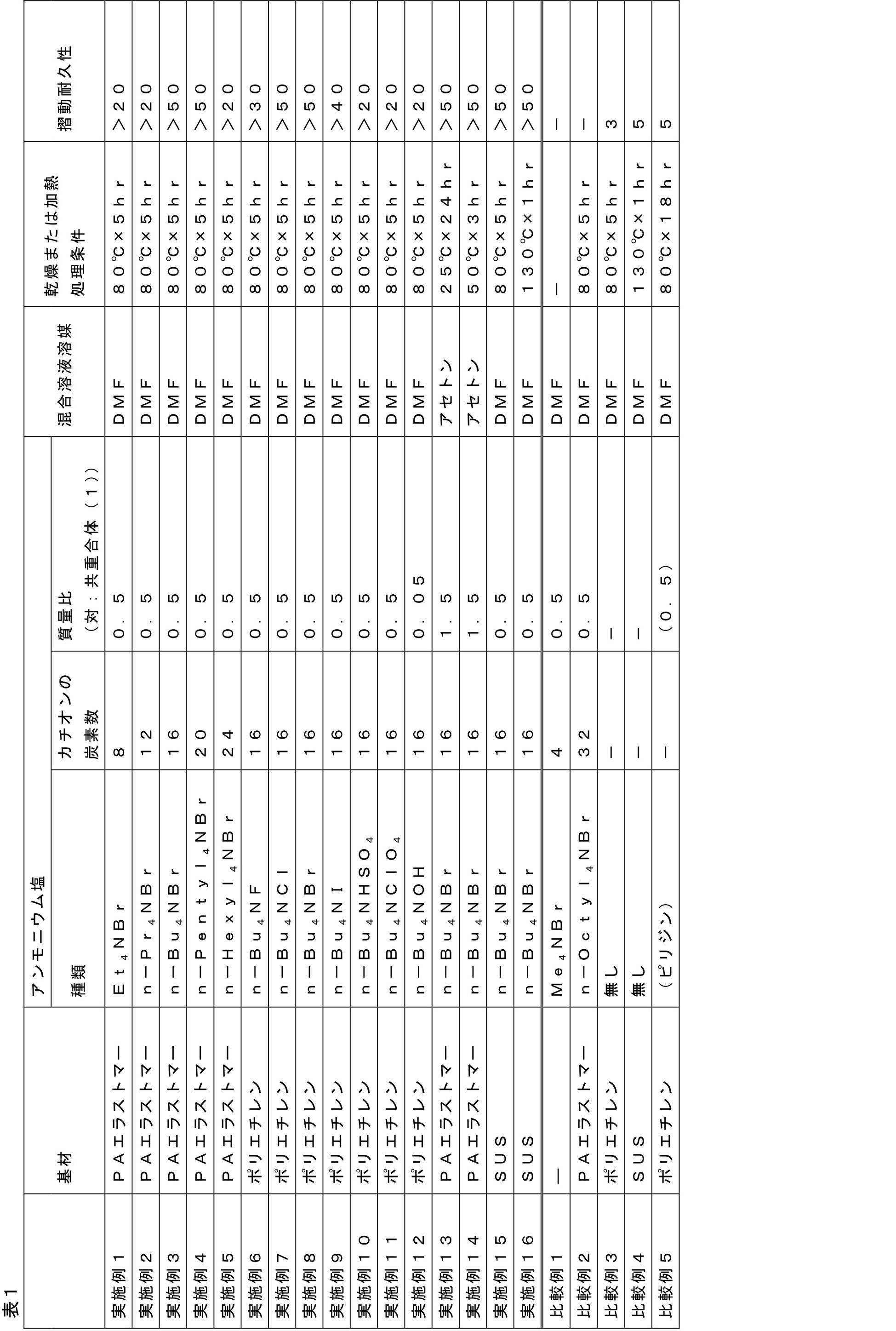
上記表1より、特定のアンモニウム塩を含む混合溶液を用いることにより、摺動耐久性に優れる潤滑層を有する医療用具が得られることが示された。特に、実施例1~5の対比より、炭素数が16~20であるアンモニウム塩を用いると、特に摺動性が向上することが明らかになった。また、実施例6~12の対比より、アンモニウム塩のアニオンが、ハロゲン化物イオンであると摺動耐久性が向上しやすいと言える。なかでも、アンモニウム塩のアニオンが、塩化物イオン、臭化物イオンであるとき(実施例7、8)、特に摺動耐久性が向上した。次いで、アンモニウム塩のアニオンが、ヨウ化物イオンであるときも、摺動耐久性の向上効果が良好であった(実施例9)。
さらに、本願の構成によれば、実施例13、14のように、処理温度が低温であっても良好な摺動耐久性が得られた。これは、特定のアンモニウム塩の添加により、共重合体中のグリシジル基の反応が十分に進行したことによるものと考えられる。
本出願は、2017年9月20日に出願された日本特許出願番号2017-180692号および2018年6月12日に出願された日本特許出願番号2018-111807号に基づいており、その開示内容は、参照され、全体として、組み入れられている。
10 医療用具
1 基材層
1a 基材層コア部
1b 基材表面層
2 潤滑層
1 基材層
1a 基材層コア部
1b 基材表面層
2 潤滑層
Claims (11)
- 基材層と、前記基材層の少なくとも一部に担持された潤滑層と、を備える医療用具の製造方法であって、
エポキシ基を有する反応性単量体由来の構成単位(A)および親水性単量体由来の構成単位(B)を有するブロック共重合体と、8以上24以下の炭素原子を有するアルキルアンモニウム塩と、溶媒とを含む溶液を前記基材層上に塗布し、洗浄することを含む、医療用具の製造方法。 - 前記溶液を前記基材層上に塗布した後、110℃以下で維持する、請求項1に記載の医療用具の製造方法。
- 前記アルキルアンモニウム塩が、テトラアルキルアンモニウム塩である、請求項1または2に記載の医療用具の製造方法。
- 前記アルキルアンモニウム塩が、テトラエチルアンモニウム塩、テトラn-プロピルアンモニウム塩、テトラn-ブチルアンモニウム塩、テトラn-ペンチルアンモニウム塩、およびテトラn-ヘキシルアンモニウム塩からなる群から選択される、請求項1~3のいずれか1項に記載の医療用具の製造方法。
- 前記アルキルアンモニウム塩のアニオンが、ハロゲン化物イオン、硫酸水素イオン、過塩素酸イオン、および水酸化物イオンからなる群から選択される、請求項1~4のいずれか1項に記載の医療用具の製造方法。
- 前記アルキルアンモニウム塩のアニオンが、ハロゲン化物イオンである、請求項1~5のいずれか1項に記載の医療用具の製造方法。
- 前記アルキルアンモニウム塩が、16以上20以下の炭素原子を有する、請求項1~6のいずれか1項に記載の医療用具の製造方法。
- 前記エポキシ基を有する反応性単量体は、グリシジルアクリレート、グリシジルメタクリレート、3,4-エポキシシクロヘキシルメチルアクリレート、3,4-エポキシシクロヘキシルメチルメタクリレート、β-メチルグリシジルメタクリレート、およびアリルグリシジルエーテルからなる群から選択される少なくとも一種を含む、請求項1~7のいずれか1項に記載の医療用具の製造方法。
- 前記親水性単量体は、N,N-ジメチルアクリルアミド、アクリルアミド、2-ヒドロキシエチルメタクリレート、およびN-ビニルピロリドンからなる群から選択される少なくとも一種を含む、請求項1~8のいずれか1項に記載の医療用具の製造方法。
- 前記溶液が、前記ブロック共重合体を1~10質量%含む、請求項1~9のいずれか1項に記載の医療用具の製造方法。
- 前記溶液が、前記ブロック共重合体と、前記アルキルアンモニウム塩とを、1:0.05~2の質量比で含む、請求項1~10のいずれか1項に記載の医療用具の製造方法。
Priority Applications (4)
| Application Number | Priority Date | Filing Date | Title |
|---|---|---|---|
| JP2019543605A JP7140769B2 (ja) | 2017-09-20 | 2018-09-13 | 医療用具の製造方法 |
| EP18858334.8A EP3669901B1 (en) | 2017-09-20 | 2018-09-13 | Method for producing medical instrument |
| CN201880055951.5A CN111050817B (zh) | 2017-09-20 | 2018-09-13 | 医疗用具的制造方法 |
| US16/808,777 US11969525B2 (en) | 2017-09-20 | 2020-03-04 | Method for producing medical instrument |
Applications Claiming Priority (4)
| Application Number | Priority Date | Filing Date | Title |
|---|---|---|---|
| JP2017180692 | 2017-09-20 | ||
| JP2017-180692 | 2017-09-20 | ||
| JP2018111807 | 2018-06-12 | ||
| JP2018-111807 | 2018-06-12 |
Related Child Applications (1)
| Application Number | Title | Priority Date | Filing Date |
|---|---|---|---|
| US16/808,777 Continuation US11969525B2 (en) | 2017-09-20 | 2020-03-04 | Method for producing medical instrument |
Publications (1)
| Publication Number | Publication Date |
|---|---|
| WO2019059106A1 true WO2019059106A1 (ja) | 2019-03-28 |
Family
ID=65809801
Family Applications (1)
| Application Number | Title | Priority Date | Filing Date |
|---|---|---|---|
| PCT/JP2018/034070 WO2019059106A1 (ja) | 2017-09-20 | 2018-09-13 | 医療用具の製造方法 |
Country Status (5)
| Country | Link |
|---|---|
| US (1) | US11969525B2 (ja) |
| EP (1) | EP3669901B1 (ja) |
| JP (1) | JP7140769B2 (ja) |
| CN (1) | CN111050817B (ja) |
| WO (1) | WO2019059106A1 (ja) |
Families Citing this family (1)
| Publication number | Priority date | Publication date | Assignee | Title |
|---|---|---|---|---|
| CN115920141B (zh) * | 2022-12-12 | 2024-03-19 | 广东省人民医院 | 一种抗菌抗微生物黏附引流管及其制备方法 |
Citations (10)
| Publication number | Priority date | Publication date | Assignee | Title |
|---|---|---|---|---|
| JPH01292025A (ja) * | 1988-05-18 | 1989-11-24 | Toshiba Corp | エポキシ樹脂組成物 |
| JPH0263819A (ja) | 1988-08-31 | 1990-03-05 | Mitsubishi Plastics Ind Ltd | 両面エンボス加工方法 |
| JPH0415278A (ja) * | 1990-05-10 | 1992-01-20 | Kansai Paint Co Ltd | 熱硬化形水性塗料組成物 |
| JPH07233233A (ja) * | 1994-02-23 | 1995-09-05 | Sanyo Chem Ind Ltd | 樹脂硬化用触媒およびその製造法 |
| JPH0833704A (ja) | 1994-07-22 | 1996-02-06 | Terumo Corp | 湿潤時に表面が潤滑性を有する医療用具及びその製造方法 |
| JP2002145971A (ja) | 2000-11-13 | 2002-05-22 | Japan Science & Technology Corp | ナノ構造機能体 |
| JP2006316169A (ja) | 2005-05-12 | 2006-11-24 | Chisso Corp | 固形潤滑材 |
| JP2012161372A (ja) * | 2011-02-03 | 2012-08-30 | Terumo Corp | 医療用具およびその製造方法 |
| JP2017180692A (ja) | 2016-03-30 | 2017-10-05 | 株式会社ショーワ | 油圧緩衝器 |
| JP2018111807A (ja) | 2016-12-23 | 2018-07-19 | 奇美實業股▲分▼有限公司 | 熱可塑性樹脂組成物およびそれから形成された成形品 |
Family Cites Families (11)
| Publication number | Priority date | Publication date | Assignee | Title |
|---|---|---|---|---|
| CA2033382A1 (en) * | 1989-12-29 | 1991-06-30 | Akira Tominaga | Thermosetting coating composition and pigmented film formation |
| US5218018A (en) | 1989-12-29 | 1993-06-08 | Kansai Paint Co., Ltd. | Hydroxyl and carboxyl groups-containing resin with alicyclic polyepoxide |
| US5670558A (en) * | 1994-07-07 | 1997-09-23 | Terumo Kabushiki Kaisha | Medical instruments that exhibit surface lubricity when wetted |
| US5939208A (en) * | 1997-11-07 | 1999-08-17 | Biomimetics, Inc. | Method for creation of biomimetic surfaces |
| US20040198882A1 (en) * | 2003-03-31 | 2004-10-07 | Fuji Photo Film Co., Ltd. | Silica-containing coating composition for forming films and method for forming silica-containing films |
| EP2088173B1 (en) * | 2006-11-22 | 2012-02-22 | Kaneka Corporation | Curable composition and catalyst composition |
| WO2010087286A1 (ja) * | 2009-01-28 | 2010-08-05 | テルモ株式会社 | 湿潤時に表面が潤滑性を有する医療用具 |
| JP2015057081A (ja) * | 2012-01-13 | 2015-03-26 | テルモ株式会社 | 潤滑コート剤および当該潤滑コート剤で被覆されてなる医療デバイス |
| EP2982390B1 (en) * | 2013-04-01 | 2020-04-22 | Terumo Kabushiki Kaisha | Medical device and method for manufacturing medical device |
| JP6357156B2 (ja) * | 2013-09-02 | 2018-07-11 | テルモ株式会社 | 医療用具およびその製造方法 |
| CN106999636B (zh) * | 2014-11-26 | 2020-08-04 | 泰尔茂株式会社 | 医疗用具及其制造方法 |
-
2018
- 2018-09-13 JP JP2019543605A patent/JP7140769B2/ja active Active
- 2018-09-13 EP EP18858334.8A patent/EP3669901B1/en active Active
- 2018-09-13 WO PCT/JP2018/034070 patent/WO2019059106A1/ja unknown
- 2018-09-13 CN CN201880055951.5A patent/CN111050817B/zh active Active
-
2020
- 2020-03-04 US US16/808,777 patent/US11969525B2/en active Active
Patent Citations (10)
| Publication number | Priority date | Publication date | Assignee | Title |
|---|---|---|---|---|
| JPH01292025A (ja) * | 1988-05-18 | 1989-11-24 | Toshiba Corp | エポキシ樹脂組成物 |
| JPH0263819A (ja) | 1988-08-31 | 1990-03-05 | Mitsubishi Plastics Ind Ltd | 両面エンボス加工方法 |
| JPH0415278A (ja) * | 1990-05-10 | 1992-01-20 | Kansai Paint Co Ltd | 熱硬化形水性塗料組成物 |
| JPH07233233A (ja) * | 1994-02-23 | 1995-09-05 | Sanyo Chem Ind Ltd | 樹脂硬化用触媒およびその製造法 |
| JPH0833704A (ja) | 1994-07-22 | 1996-02-06 | Terumo Corp | 湿潤時に表面が潤滑性を有する医療用具及びその製造方法 |
| JP2002145971A (ja) | 2000-11-13 | 2002-05-22 | Japan Science & Technology Corp | ナノ構造機能体 |
| JP2006316169A (ja) | 2005-05-12 | 2006-11-24 | Chisso Corp | 固形潤滑材 |
| JP2012161372A (ja) * | 2011-02-03 | 2012-08-30 | Terumo Corp | 医療用具およびその製造方法 |
| JP2017180692A (ja) | 2016-03-30 | 2017-10-05 | 株式会社ショーワ | 油圧緩衝器 |
| JP2018111807A (ja) | 2016-12-23 | 2018-07-19 | 奇美實業股▲分▼有限公司 | 熱可塑性樹脂組成物およびそれから形成された成形品 |
Non-Patent Citations (3)
| Title |
|---|
| KUBO, T ET AL.: "Antibacterial activities effectuated by co-continuous epoxy-based polymer materials", COLLOIDS AND SURFACES B: BIOINTERFACES, vol. 107, 2013, pages 53 - 58, XP055584251, ISSN: 0927-7765, DOI: 10.1016/j.colsurfb.2013.01.043 * |
| See also references of EP3669901A4 |
| TANAKA RYOHEI: "Characteristics of epoxy resin", SHIKIZAI KYOKAISHI - COLOUR MATERIAL, vol. 64, no. 10, 1991, JAPAN, pages 655 - 665, XP009519604 * |
Also Published As
| Publication number | Publication date |
|---|---|
| EP3669901A4 (en) | 2020-11-25 |
| JPWO2019059106A1 (ja) | 2020-11-05 |
| EP3669901A1 (en) | 2020-06-24 |
| EP3669901B1 (en) | 2021-11-24 |
| US11969525B2 (en) | 2024-04-30 |
| US20200197576A1 (en) | 2020-06-25 |
| CN111050817A (zh) | 2020-04-21 |
| JP7140769B2 (ja) | 2022-09-21 |
| CN111050817B (zh) | 2022-03-25 |
Similar Documents
| Publication | Publication Date | Title |
|---|---|---|
| JP6619360B2 (ja) | 医療用具およびその製造方法 | |
| US9782521B2 (en) | Medical device and method for producing medical device | |
| JP2018000746A (ja) | 医療用具 | |
| US20210102019A1 (en) | Hydrophilic copolymer and medical device | |
| JPWO2019142710A1 (ja) | 医療用コーティング材料および該医療用コーティング材料を利用した医療用具 | |
| US20200197576A1 (en) | Method for producing medical instrument | |
| JP7389102B2 (ja) | 医療用具の製造方法および医療用具 | |
| JP2020028639A (ja) | 医療用具の製造方法および医療用具 | |
| JP2016150163A (ja) | 医療用具の製造方法 | |
| JP2024010351A (ja) | 医療用具 | |
| JP2013169283A (ja) | 医療用具の製造方法および医療用具 | |
| JP2020039826A (ja) | 医療用具の製造方法および医療用具 | |
| JP2020028640A (ja) | 医療用具の製造方法および医療用具 |
Legal Events
| Date | Code | Title | Description |
|---|---|---|---|
| 121 | Ep: the epo has been informed by wipo that ep was designated in this application |
Ref document number: 18858334 Country of ref document: EP Kind code of ref document: A1 |
|
| ENP | Entry into the national phase |
Ref document number: 2019543605 Country of ref document: JP Kind code of ref document: A |
|
| NENP | Non-entry into the national phase |
Ref country code: DE |
|
| ENP | Entry into the national phase |
Ref document number: 2018858334 Country of ref document: EP Effective date: 20200318 |