WO2019049993A1 - シフトレンジ制御装置 - Google Patents
シフトレンジ制御装置 Download PDFInfo
- Publication number
- WO2019049993A1 WO2019049993A1 PCT/JP2018/033229 JP2018033229W WO2019049993A1 WO 2019049993 A1 WO2019049993 A1 WO 2019049993A1 JP 2018033229 W JP2018033229 W JP 2018033229W WO 2019049993 A1 WO2019049993 A1 WO 2019049993A1
- Authority
- WO
- WIPO (PCT)
- Prior art keywords
- motor
- angle
- acceleration
- moving average
- shift range
- Prior art date
- Legal status (The legal status is an assumption and is not a legal conclusion. Google has not performed a legal analysis and makes no representation as to the accuracy of the status listed.)
- Ceased
Links
Images


Classifications
-
- B—PERFORMING OPERATIONS; TRANSPORTING
- B60—VEHICLES IN GENERAL
- B60W—CONJOINT CONTROL OF VEHICLE SUB-UNITS OF DIFFERENT TYPE OR DIFFERENT FUNCTION; CONTROL SYSTEMS SPECIALLY ADAPTED FOR HYBRID VEHICLES; ROAD VEHICLE DRIVE CONTROL SYSTEMS FOR PURPOSES NOT RELATED TO THE CONTROL OF A PARTICULAR SUB-UNIT
- B60W30/00—Purposes of road vehicle drive control systems not related to the control of a particular sub-unit, e.g. of systems using conjoint control of vehicle sub-units
- B60W30/18—Propelling the vehicle
- B60W30/19—Improvement of gear change, e.g. by synchronisation or smoothing gear shift
-
- F—MECHANICAL ENGINEERING; LIGHTING; HEATING; WEAPONS; BLASTING
- F16—ENGINEERING ELEMENTS AND UNITS; GENERAL MEASURES FOR PRODUCING AND MAINTAINING EFFECTIVE FUNCTIONING OF MACHINES OR INSTALLATIONS; THERMAL INSULATION IN GENERAL
- F16H—GEARING
- F16H61/00—Control functions within control units of change-speed- or reversing-gearings for conveying rotary motion ; Control of exclusively fluid gearing, friction gearing, gearings with endless flexible members or other particular types of gearing
- F16H61/26—Generation or transmission of movements for final actuating mechanisms
- F16H61/28—Generation or transmission of movements for final actuating mechanisms with at least one movement of the final actuating mechanism being caused by a non-mechanical force, e.g. power-assisted
-
- B—PERFORMING OPERATIONS; TRANSPORTING
- B60—VEHICLES IN GENERAL
- B60W—CONJOINT CONTROL OF VEHICLE SUB-UNITS OF DIFFERENT TYPE OR DIFFERENT FUNCTION; CONTROL SYSTEMS SPECIALLY ADAPTED FOR HYBRID VEHICLES; ROAD VEHICLE DRIVE CONTROL SYSTEMS FOR PURPOSES NOT RELATED TO THE CONTROL OF A PARTICULAR SUB-UNIT
- B60W10/00—Conjoint control of vehicle sub-units of different type or different function
- B60W10/04—Conjoint control of vehicle sub-units of different type or different function including control of propulsion units
- B60W10/06—Conjoint control of vehicle sub-units of different type or different function including control of propulsion units including control of combustion engines
-
- B—PERFORMING OPERATIONS; TRANSPORTING
- B60—VEHICLES IN GENERAL
- B60W—CONJOINT CONTROL OF VEHICLE SUB-UNITS OF DIFFERENT TYPE OR DIFFERENT FUNCTION; CONTROL SYSTEMS SPECIALLY ADAPTED FOR HYBRID VEHICLES; ROAD VEHICLE DRIVE CONTROL SYSTEMS FOR PURPOSES NOT RELATED TO THE CONTROL OF A PARTICULAR SUB-UNIT
- B60W10/00—Conjoint control of vehicle sub-units of different type or different function
- B60W10/10—Conjoint control of vehicle sub-units of different type or different function including control of change-speed gearings
- B60W10/11—Stepped gearings
-
- H—ELECTRICITY
- H02—GENERATION; CONVERSION OR DISTRIBUTION OF ELECTRIC POWER
- H02P—CONTROL OR REGULATION OF ELECTRIC MOTORS, ELECTRIC GENERATORS OR DYNAMO-ELECTRIC CONVERTERS; CONTROLLING TRANSFORMERS, REACTORS OR CHOKE COILS
- H02P29/00—Arrangements for regulating or controlling electric motors, appropriate for both AC and DC motors
-
- B—PERFORMING OPERATIONS; TRANSPORTING
- B60—VEHICLES IN GENERAL
- B60W—CONJOINT CONTROL OF VEHICLE SUB-UNITS OF DIFFERENT TYPE OR DIFFERENT FUNCTION; CONTROL SYSTEMS SPECIALLY ADAPTED FOR HYBRID VEHICLES; ROAD VEHICLE DRIVE CONTROL SYSTEMS FOR PURPOSES NOT RELATED TO THE CONTROL OF A PARTICULAR SUB-UNIT
- B60W2510/00—Input parameters relating to a particular sub-units
- B60W2510/06—Combustion engines, Gas turbines
- B60W2510/0638—Engine speed
- B60W2510/0652—Speed change rate
-
- B—PERFORMING OPERATIONS; TRANSPORTING
- B60—VEHICLES IN GENERAL
- B60W—CONJOINT CONTROL OF VEHICLE SUB-UNITS OF DIFFERENT TYPE OR DIFFERENT FUNCTION; CONTROL SYSTEMS SPECIALLY ADAPTED FOR HYBRID VEHICLES; ROAD VEHICLE DRIVE CONTROL SYSTEMS FOR PURPOSES NOT RELATED TO THE CONTROL OF A PARTICULAR SUB-UNIT
- B60W2510/00—Input parameters relating to a particular sub-units
- B60W2510/06—Combustion engines, Gas turbines
- B60W2510/0657—Engine torque
-
- B—PERFORMING OPERATIONS; TRANSPORTING
- B60—VEHICLES IN GENERAL
- B60W—CONJOINT CONTROL OF VEHICLE SUB-UNITS OF DIFFERENT TYPE OR DIFFERENT FUNCTION; CONTROL SYSTEMS SPECIALLY ADAPTED FOR HYBRID VEHICLES; ROAD VEHICLE DRIVE CONTROL SYSTEMS FOR PURPOSES NOT RELATED TO THE CONTROL OF A PARTICULAR SUB-UNIT
- B60W2510/00—Input parameters relating to a particular sub-units
- B60W2510/06—Combustion engines, Gas turbines
- B60W2510/0685—Engine crank angle
-
- B—PERFORMING OPERATIONS; TRANSPORTING
- B60—VEHICLES IN GENERAL
- B60W—CONJOINT CONTROL OF VEHICLE SUB-UNITS OF DIFFERENT TYPE OR DIFFERENT FUNCTION; CONTROL SYSTEMS SPECIALLY ADAPTED FOR HYBRID VEHICLES; ROAD VEHICLE DRIVE CONTROL SYSTEMS FOR PURPOSES NOT RELATED TO THE CONTROL OF A PARTICULAR SUB-UNIT
- B60W2710/00—Output or target parameters relating to a particular sub-units
- B60W2710/10—Change speed gearings
-
- F—MECHANICAL ENGINEERING; LIGHTING; HEATING; WEAPONS; BLASTING
- F16—ENGINEERING ELEMENTS AND UNITS; GENERAL MEASURES FOR PRODUCING AND MAINTAINING EFFECTIVE FUNCTIONING OF MACHINES OR INSTALLATIONS; THERMAL INSULATION IN GENERAL
- F16H—GEARING
- F16H61/00—Control functions within control units of change-speed- or reversing-gearings for conveying rotary motion ; Control of exclusively fluid gearing, friction gearing, gearings with endless flexible members or other particular types of gearing
- F16H61/26—Generation or transmission of movements for final actuating mechanisms
- F16H61/28—Generation or transmission of movements for final actuating mechanisms with at least one movement of the final actuating mechanism being caused by a non-mechanical force, e.g. power-assisted
- F16H2061/283—Adjustment or calibration of actuator positions, e.g. neutral position
Definitions
- the present disclosure relates to a shift range control device.
- a shift range switching device that switches a shift range by controlling a motor according to a shift range switching request from a driver.
- the detection value of an output shaft sensor is used for the drive control of a motor.
- Patent Document 1 when the detection value of the output shaft sensor can not be used, there is a possibility that the motor can not be accurately positioned and controlled.
- An object of the present disclosure is to provide a shift range control device capable of realizing highly accurate positioning control.
- the shift range control device of the present disclosure switches a shift range by controlling driving of a motor, and includes an angle calculation unit, an acceleration calculation unit, a moving average calculation unit, and a drive control unit.
- the angle calculation unit calculates a motor angle based on a motor rotation angle signal acquired from a motor rotation angle sensor that detects a rotational position of the motor.
- the acceleration calculation unit calculates motor acceleration based on the motor angle.
- the moving average calculation unit calculates an acceleration moving average value which is a moving average of at least one of an electrical angle predetermined period of the motor acceleration and a predetermined mechanical angle period.
- the drive control unit uses the acceleration moving average value to control the driving of the motor such that the motor angle becomes a motor angle target value corresponding to the target shift range. Since the vibration component of the motor acceleration can be reduced by calculating the acceleration moving average value, it is possible to realize high-accuracy positioning control using the acceleration moving average value.
- FIG. 1 is a perspective view of a shift-by-wire system according to one embodiment
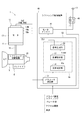
- Figure 2 is a schematic block diagram illustrating a shift-by-wire system according to one embodiment
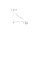
- FIG. 3 is an explanatory view for explaining a map used for calculating a motor torque according to one embodiment
- Figure 4 is a schematic diagram illustrating the play between the motor and the output shaft according to one embodiment
- FIG. 5 is a flowchart illustrating a target setting process according to an embodiment
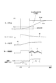
- FIG. 6 is a time chart explaining the motor drive control process according to an embodiment.
- the shift-by-wire system 1 which is a shift range switching system, includes a motor 10, a shift range switching mechanism 20, a parking lock mechanism 30, a shift range control device 40, and the like.
- the motor 10 is rotated by being supplied with electric power from a battery mounted on a vehicle (not shown), and functions as a drive source of the shift range switching mechanism 20.
- the motor 10 of the present embodiment is a permanent magnet type DC brushless motor.
- an encoder 13 as a motor rotation angle sensor detects the rotational position of a rotor (not shown) of the motor 10.
- the encoder 13 is, for example, a magnetic rotary encoder, and includes a magnet that rotates integrally with the rotor, and a Hall IC for magnetic detection.
- the encoder 13 outputs A-phase and B-phase pulse signals at predetermined angles in synchronization with the rotation of the rotor.
- the signal from the encoder 13 is referred to as a motor rotation angle signal SgE.
- the reduction gear 14 is provided between the motor shaft 105 (see FIG. 4) of the motor 10 and the output shaft 15, and decelerates the rotation of the motor 10 and outputs the same to the output shaft 15.
- the rotation of the motor 10 is transmitted to the shift range switching mechanism 20.
- an output shaft sensor for detecting the rotational position of the output shaft 15 is omitted.
- the shift range switching mechanism 20 has a detent plate 21 and a detent spring 25 and the like, and the rotational driving force output from the reduction gear 14 is a manual valve 28 and a parking lock mechanism 30. Transmit to The detent plate 21 is fixed to the output shaft 15 and driven by the motor 10.
- the direction in which the detent plate 21 separates from the base of the detent spring 25 is the forward rotation direction
- the direction in which the detent plate 21 approaches the base is the reverse rotation direction.
- the detent plate 21 is provided with a pin 24 projecting in parallel with the output shaft 15.
- the pin 24 is connected to the manual valve 28.
- the shift range switching mechanism 20 converts the rotational movement of the motor 10 into a linear movement and transmits it to the manual valve 28.
- the manual valve 28 is provided on the valve body 29. The manual valve 28 reciprocates in the axial direction, thereby switching the hydraulic pressure supply path to the hydraulic clutch (not shown), and switching the engagement state of the hydraulic clutch changes the shift range.
- Two recesses 22 and 23 are provided on the detent spring 25 side of the detent plate 21.
- the side closer to the base of the detent spring 25 is referred to as the recess 22, and the side farther from the base is referred to as the recess 23.
- the recess 22 corresponds to the NotP range other than the P range
- the recess 23 corresponds to the P range.
- the detent spring 25 is an elastically deformable plate-like member, and the detent roller 26 is provided at the tip.
- the detent spring 25 biases the detent roller 26 toward the rotation center of the detent plate 21.
- the detent spring 25 elastically deforms, and the detent roller 26 moves between the concave portions 22 and 23.
- the detent roller 26 By the detent roller 26 being fitted in either of the recessed portions 22 and 23, the swing of the detent plate 21 is restricted, the axial position of the manual valve 28 and the state of the parking lock mechanism 30 are determined, and automatic shifting is performed.
- the shift range of machine 5 is fixed.
- the detent roller 26 fits into the recess 22 when the shift range is the NotP range, and fits into the recess 23 when the shift range is the P range.
- the parking lock mechanism 30 has a parking rod 31, a cone 32, a parking lock pole 33, a shaft 34 and a parking gear 35.
- the parking rod 31 is formed in a substantially L-shape, and one end 311 side is fixed to the detent plate 21.
- a conical body 32 is provided on the other end 312 side of the parking rod 31.
- the conical body 32 is formed to decrease in diameter toward the other end 312 side.
- the parking lock pole 33 abuts on the conical surface of the conical body 32 and is provided so as to be able to pivot about the shaft 34.
- a protrusion capable of meshing with the parking gear 35 on the parking gear 35 side of the parking lock pole 33 331 are provided.
- the parking gear 35 is provided on an axle (not shown), and is provided so as to be able to mesh with the convex portion 331 of the parking lock pole 33.
- the rotation of the axle is restricted.
- the shift range is the NotP range
- the parking gear 35 is not locked by the parking lock pole 33, and the rotation of the axle is not blocked by the parking lock mechanism 30.
- the shift range is the P range
- the parking gear 35 is locked by the parking lock pole 33, and the rotation of the axle is restricted.
- the shift range control device 40 has a motor driver 41, an ECU 50, and the like.
- the motor driver 41 has a switching element (not shown), and switches on / off of each phase (U phase, V phase, W phase) of the motor 10 by turning on / off the switching element based on a command from the ECU 50. Thereby, the drive of the motor 10 is controlled.
- a motor relay 46 is provided between the motor driver 41 and the battery. The motor relay 46 is turned on when the start switch of the vehicle such as an ignition switch is turned on, and power is supplied to the motor 10 side. Further, the motor relay 46 is turned off when the start switch is turned off, and the power supply to the motor 10 side is cut off.
- the ECU 50 is mainly composed of a microcomputer and the like, and includes a CPU, a ROM, a RAM, an I / O, and a bus line connecting these components, which are not shown.
- Each process in the ECU 50 may be a software process by executing a program stored in advance in a tangible memory device (that is, a readable non-transitory tangible recording medium) such as a ROM by a CPU, or may be dedicated It may be hardware processing by an electronic circuit.
- the ECU 50 controls the switching of the shift range by controlling the drive of the motor 10 based on the driver request shift range, the signal from the brake switch, the vehicle speed, and the like. Further, the ECU 50 controls the driving of the shift hydraulic control solenoid 6 based on the vehicle speed, the accelerator opening degree, the driver's requested shift range, and the like. By controlling the shift hydraulic control solenoid 6, the gear is controlled.
- the transmission hydraulic control solenoid 6 is provided in a number corresponding to the number of shift stages and the like. In the present embodiment, one ECU 50 controls the drive of the motor 10 and the solenoid 6, but the motor control ECU for controlling the motor 10 may be divided into an AT-ECU for solenoid control. Hereinafter, drive control of the motor 10 will be mainly described.
- the ECU 50 includes a parameter calculation unit 51, a drive control unit 55, and the like.
- the parameter calculation unit 51 calculates an encoder count value ⁇ en which is a count value of the encoder 13 based on the motor rotation angle signal SgE output from the encoder 13.
- the encoder count value ⁇ en is a value corresponding to the actual mechanical angle and electrical angle of the motor 10. In the present embodiment, the encoder count value ⁇ en corresponds to the “motor angle”.
- the encoder count value ⁇ en is calculated for each edge interruption of the motor rotation angle signal SgE.
- the parameter calculator 51 calculates the motor speed SPm [deg / s] for each edge interruption of the motor rotation angle signal SgE (see equation (1)).
- the constant ke in the equation is the motor rotation angle corresponding to one count of the encoder count value ⁇ en, t (n) is the current interrupt time, and t (n-1) is the previous interrupt time.
- the parameter calculation unit 51 calculates the motor acceleration a [deg / s 2 ] for each edge interruption of the motor rotation angle signal SgE (see equation (2)).
- SPm (n) is the motor speed at the time of the current calculation
- SPm (n-1) is the motor speed at the previous calculation.
- the parameter calculator 51 calculates acceleration moving average values A and AA, which are moving average values of the motor acceleration a, at each edge interruption of the motor rotation angle signal SgE.
- A ⁇ a (i-g + 1) + a (i-g + 2) +... + A (i-1) + a (i) ⁇ / g ... (3)
- the acceleration moving average value AA corresponding to one cycle of the mechanical angle is expressed by equation (4).
- AA ⁇ A (i-h + 1) + A (i-h + 2) +... + A (i-1) + A (i) ⁇ / h ... (4)
- the parameter calculator 51 calculates the estimated load torque TL [Nm].
- the estimated load torque TL is calculated by equation (5).
- TL TM (SPm) -ki x AA (5)
- the TM (SPm) in the equation means that the motor torque TM is a function based on the motor speed SPm.
- the motor torque TM is calculated using the map shown in FIG. As shown in FIG. 3, the motor torque TM takes a larger value as the motor speed SPm decreases.
- the constant ki in the equation is a value corresponding to the inertia.
- the calculated estimated load torque TL uses the filtered value for free running determination.
- the estimated load torque TL is a value after filter processing.
- the values calculated by the parameter calculation unit 51 are used for various control calculations and the like.
- the drive control unit 55 includes an idle determination unit 56, a target setting unit 57, and a signal generation unit 58.
- the idle determination unit 56 determines whether the motor 10 is in the idle state in which the motor 10 is rotating in the range of the play between the motor shaft 105 and the output shaft 15.
- the free running determination unit 56 detects the timing at which the free running state ends by the free running determination.
- free running determination is performed based on the estimated load torque TL calculated using the acceleration moving average value AA.
- the target setting unit 57 sets a target shift range based on a driver request shift range based on a shift switch or the like, a vehicle speed, a signal from a brake switch, and the like. Further, the target setting unit 57 sets a target count value ⁇ cmd, which is a motor angle target value, according to the target shift range and the like. Further, the target count value ⁇ cmd is corrected with the angle correction value ⁇ p according to the encoder count value ⁇ en at the end of the free run.
- the signal generation unit 58 generates a control signal related to drive control of the motor 10 by feedback control or the like so that the motor 10 stops at a rotational position where the encoder count value ⁇ en becomes the target count value ⁇ cmd.
- the generated control signal is output to the motor driver 41.
- the details of the drive control of the motor 10 may be arbitrary.
- FIG. 4 the relationship between the motor shaft 105 which is the rotation shaft of the motor 10, the output shaft 15, and the detent plate 21 is shown in FIG.
- the detent roller 26 rides over the mountain portion 210 between the recessed portions 22 and 23 of the detent plate 21 and the driver requested shift range
- the state which inserts in the recessed parts 22 and 23 according to 3 is shown typically.
- switching from the P range to the not P range will be described as an example.
- the rotational direction of the motor 10 and the output shaft 15 will be described as the left-right direction in the drawing. Further, FIG.
- FIG. 4 is a schematic view conceptually showing “play”, in which the output shaft 15 and the reduction gear 14 are integrated, and the motor shaft 105 is movable within the range of the reduction gear 14 Although the motor shaft 105 and the reduction gear 14 are integrated as one, it may be configured such that "play” exists between the reduction gear 14 and the output shaft 15 Absent.
- a reduction gear 14 is provided between the motor shaft 105 and the output shaft 15, and there is “play” including gear backlash between the motor shaft 105 and the output shaft 15. doing.
- the motor 10 is a DC brushless motor, and when energization of the motor 10 is stopped, the motor shaft 105 rotates within the range of play due to the influence of cogging torque or the like. And the reduction gear 14 may be separated.
- the motor 10 When the loose run is finished, the motor 10, the output shaft 15, and the detent plate 21 rotate integrally. As a result, the detent roller 26 rides over the ridge 210 between the recesses 22 and 23 and moves to the recess 22.
- a section in which the detent roller 26 is moving between the recessed portions 22 and 23 after the end of the looseness running state is referred to as a "valley-valley rotation section”. Further, a section from the end of the rattle free running state to the point before crossing over the top of the mountain portion 210 is referred to as an "integrated rotation section".
- Patent Document 1 the amount of play is learned by executing abutment control.
- the motor 10 is rotated to the limit position of the movable range with a relatively large torque, so the detent mechanism of the shift range switching mechanism 20 is stressed. Therefore, it is necessary to design the shift range switching mechanism 20 so as not to be damaged even if stress in abutment control is applied.
- the drive of the motor 10 is controlled without using the information related to the rotational position of the output shaft 15 based on the output shaft sensor and without performing the abutment control.
- position control accuracy is secured by detecting the end of free running on the basis of the estimated load torque TL and correcting the target count value ⁇ cmd.
- step S101 The target setting process of this embodiment will be described based on the flowchart shown in FIG.
- the “step” of step S101 is omitted and simply referred to as the symbol “S”.
- the state in which the flag is set is "1"
- the state in which the flag is not set is "0”.
- the free running determination unit 56 acquires the parameter calculated by the parameter calculation unit 51.
- the estimated load torque TL is acquired.
- the idle determination unit 56 determines whether the energization flag is set.
- the energization flag is set when the target shift range is changed, and is reset after it is determined that the motor 10 has stopped.
- the target count value ⁇ cmd is set to a temporary value ⁇ t, and driving of the motor 10 is started. If it is determined that the energization flag is not set (S102: NO), the process proceeds to S103. If it is determined that the energization flag is set (S102: YES), the process proceeds to S104.
- the free running determination unit 56 stores the current encoder count value ⁇ en as a drive initial value ⁇ init in a RAM or the like (not shown). Further, the free-running judging unit 56 resets the learning flag Xgata. If the learning flag Xgata is reset, the reset state is maintained.
- the free-running determination unit 56 determines whether the learning flag Xgata is set. If it is determined that the learning flag Xgata is set (S104: YES), this routine ends. If it is determined that the learning flag Xgata is not set (S104: NO), the process proceeds to S105.
- the idle running determination unit 56 determines whether the estimated load torque TL is larger than the load determination threshold TLth. When it is determined that the estimated load torque TL is equal to or less than the load determination threshold value TLth (S105: NO), it is determined that the rattle is running, and this routine is ended. If it is determined that the estimated load torque TL is larger than the load determination threshold value TLth (S105: YES), it is determined that the idle state has ended, and the process proceeds to S106.
- the free-running judgment unit 56 stores the current encoder count value ⁇ en as an angle correction value ⁇ p in a storage unit such as a RAM (not shown).
- the target setting unit 57 calculates a target count value ⁇ cmd based on the angle correction value ⁇ p and the designed valley-angle angle ⁇ det (see Equation (6)).
- the motor drive control process of this embodiment will be described based on the time chart of FIG.
- the motor angle, the motor torque TM, the motor speed SPm, the motor acceleration, and the estimated load torque TL are shown from the top.
- the solid line indicates the motor acceleration a
- the broken line indicates the acceleration movement average value A for one electrical angle cycle
- the one-dot chain line indicates the acceleration movement average AA for one mechanical angle cycle.
- the time scale and the like are appropriately changed.
- the motor 10 will be described as rotating in the forward direction.
- the energization flag is set, the target count value ⁇ cmd is set to the temporary value ⁇ t, and the driving of the motor 10 is started. Since the target count value ⁇ cmd is corrected before the detent roller 26 exceeds the peak portion 210, the temporary value ⁇ t can be set to any value that can get over the peak portion 210.
- the encoder count value ⁇ en and the motor speed SPm increase. Also, the motor acceleration a becomes substantially constant at a certain value. Further, as the motor speed SPm increases, the motor torque TM decreases from the drive initial torque. When the rattle free running state ends and the motor 10 and the output shaft 15 come to rotate integrally, the change amounts of the motor speed SPm and the motor torque TM become small. Also, the motor acceleration decreases and the estimated load torque TL increases.
- the estimated load torque TL will be described.
- motor friction is a load.
- the load torque T2 in the integral rotation section is larger than the load torque T1 in the free running section. That is, T1 ⁇ T2.
- a load determination threshold value TLth that is between load torques T1 and T2 is set, and it is determined that the idle state ends at time x11 when the estimated load torque TL becomes larger than the load determination threshold value TLth. Then, with the encoder count value ⁇ en at this time as the angle correction value ⁇ p, the target count value ⁇ cmd is calculated based on the angle correction value ⁇ p (see equation (6)).
- FIG. 6 ignores the operation delay and the like and calculates the target count value ⁇ cmd at the same time as the target count value ⁇ cmd is calculated at time x11, the target count value ⁇ cmd is changed from the temporary value ⁇ t.
- the timing of switching may be any timing before the detent roller 26 passes over the ridge 210 of the detent plate 21.
- motor acceleration is used to calculate the estimated load torque TL.
- the motor acceleration a may have a large vibration component and a noisy value, particularly in the valley-to-valley rotation section.
- the estimated load torque TL is calculated using the motor acceleration a containing a large amount of noise components, the estimated load torque TL also contains a large amount of noise components, and there is a possibility that the end of the loose running state can not be determined appropriately.
- the motor acceleration a vibrates by a motor torque ripple of a 360 ° electrical angle cycle and a torque ripple according to a gear efficiency of a 360 ° mechanical angle cycle.
- the high frequency vibration component of the motor acceleration a can be reduced.
- the low-frequency vibration component of the motor acceleration a can be reduced by calculating the acceleration moving average value AA for the mechanical angle of 360 ° using the acceleration moving average value A for the electrical angle of 360 °.
- the noise component included in the estimated load torque TL is reduced by calculating the estimated load torque TL using the acceleration moving average value AA, so that the rattle free running is performed using the estimated load torque TL. The end can be determined appropriately.
- the shift range control device 40 of this embodiment switches the shift range by controlling the drive of the motor 10, and includes the parameter operation unit 51 and the drive control unit 55.
- the parameter calculation unit 51 calculates an encoder count value ⁇ en, which is a motor angle, based on the motor rotation angle signal SgE acquired from the encoder 13 that detects the rotation position of the motor 10.
- the parameter calculator 51 calculates the motor acceleration a based on the encoder count value ⁇ en.
- the parameter computing unit 51 computes acceleration moving average values A and AA, which are moving averages of a predetermined period of the electric angle of the motor acceleration a and a predetermined period of the mechanical angle.
- the parameter calculation unit 51 corresponds to an “angle calculation unit”, an “acceleration calculation unit”, and a “moving average calculation unit”.
- the drive control unit 55 controls the drive of the motor 10 using the acceleration moving average values A and AA so that the encoder count value ⁇ en becomes the target count value ⁇ cmd according to the target shift range. Since the vibration component of the motor acceleration a can be reduced by calculating the acceleration moving average values A and AA, the motor using the acceleration moving average values A and AA can be used with high accuracy without using the detection value of the output axis sensor. It can control 10 drives. Therefore, highly accurate positioning control can be realized.
- the drive control unit 55 includes an idle determination unit 56 and a target setting unit 57.
- the free running determination unit 56 determines the end of the free running state in which the motor 10 is rotating within the range of play using the acceleration moving average value AA.
- the target setting unit 57 sets the target count value ⁇ cmd using the angle correction value ⁇ p according to the encoder count value ⁇ en at the end of the free run.
- the end of the idle state is determined based on the motor rotation angle signal SgE which is a signal from the encoder 13, and the target count value ⁇ cmd is set based on the encoder count value ⁇ en at the end of the idle state.
- the target count value ⁇ cmd can be appropriately set without performing learning processing of the amount of play by abutment control, and highly accurate positioning control can be realized.
- the detent mechanism is stressed because the detent roller 26 is abutted against the detent plate 21 with a relatively large torque. Therefore, it is necessary to design so that a detent mechanism etc. are not broken by abutment control. In the present embodiment, since the abutment control is unnecessary, the shift range switching mechanism 20 can be simplified.
- the output shaft sensor for detecting the rotational position of the output shaft 15 may be omitted or detected. It can reduce the accuracy. Furthermore, the free running end can be appropriately determined by using the acceleration moving average value AA in which the vibration component is reduced.
- the idle state ends. It is determined that By using the estimated load torque TL, it is possible to accurately determine the end of the idle state with relatively simple processing.
- the motor acceleration a is calculated for each pulse edge interruption of the motor rotation angle signal SgE. Thereby, the motor acceleration a can be calculated appropriately.
- the acceleration moving average value AA for one cycle of the mechanical angle is used to calculate the estimated load torque.
- the acceleration moving average value A for one cycle of the electrical angle may be used to calculate the estimated load torque.
- One of the calculation of the acceleration moving average value for the electrical angle predetermined cycle or the calculation of the acceleration moving average value for the mechanical angle predetermined cycle may be omitted.
- the value used for calculating the acceleration moving average values A and AA is not limited to one cycle of the electrical angle or the mechanical angle, but may be an arbitrary cycle number such as two cycles or half cycles. .
- the estimated load torque is calculated using the acceleration moving average values A and AA, and the free running end is determined based on the estimated load torque.
- the acceleration moving average values A and AA may be used to determine the free running end in any method. Also, for example, even when control is performed with the same duty, the acceleration varies depending on the motor temperature. Therefore, in order to change the control constant in accordance with the acceleration moving average value, the acceleration moving average value may be used for processing relating to motor control other than the free running determination.
- the motor is a DC brushless motor. In other embodiments, the motor may be any motor, such as, for example, a switched reluctance motor. In the above embodiment, although the number of winding sets of the motor is not mentioned, the number of winding sets may be one or plural.
- the motor rotation angle sensor is an encoder. In another embodiment, the motor rotation angle sensor is not limited to the encoder, and any sensor such as a resolver may be used. That is, the motor angle is not limited to the encoder count value, and may be any value that can be converted to the motor angle.
- the output shaft sensor is omitted.
- an output shaft sensor may be provided to detect the rotational position of the output shaft. For example, when the output axis sensor is normal, the end of the free running state is determined using the detection values of the motor rotation angle sensor and the output axis sensor, and when the output axis sensor becomes unusable due to a failure etc. As in the above embodiment, the end of the idle state may be determined based on the acceleration moving average value.
- the detent plate is provided with two recesses.
- the number of recesses is not limited to two, but may be any number.
- four recesses may be provided corresponding to the respective ranges of P, R, N, and D.
- the shift range switching mechanism, the parking lock mechanism, and the like may be different from the above embodiment.
- a reduction gear is provided between the motor shaft and the output shaft.
- the details of the reduction gear are not mentioned in the above embodiment, for example, a cycloid gear, a planetary gear, a spur gear that transmits torque from the reduction mechanism substantially coaxial with the motor shaft to the drive shaft, or these Any configuration may be used, such as one using a combination of
- the reduction gear between the motor shaft and the output shaft may be omitted, or a mechanism other than the reduction gear may be provided.
Landscapes
- Engineering & Computer Science (AREA)
- Chemical & Material Sciences (AREA)
- Combustion & Propulsion (AREA)
- Mechanical Engineering (AREA)
- Transportation (AREA)
- General Engineering & Computer Science (AREA)
- Automation & Control Theory (AREA)
- Power Engineering (AREA)
- Gear-Shifting Mechanisms (AREA)
- Control Of Transmission Device (AREA)
- Control Of Electric Motors In General (AREA)
Priority Applications (3)
| Application Number | Priority Date | Filing Date | Title |
|---|---|---|---|
| DE112018005032.7T DE112018005032B4 (de) | 2017-09-11 | 2018-09-07 | Schaltbereichssteuervorrichtung |
| CN201880057031.7A CN111095781B (zh) | 2017-09-11 | 2018-09-07 | 换挡挡位控制装置 |
| US16/807,568 US11084493B2 (en) | 2017-09-11 | 2020-03-03 | Shift range control device |
Applications Claiming Priority (2)
| Application Number | Priority Date | Filing Date | Title |
|---|---|---|---|
| JP2017174030A JP6838533B2 (ja) | 2017-09-11 | 2017-09-11 | シフトレンジ制御装置 |
| JP2017-174030 | 2017-09-11 |
Related Child Applications (1)
| Application Number | Title | Priority Date | Filing Date |
|---|---|---|---|
| US16/807,568 Continuation US11084493B2 (en) | 2017-09-11 | 2020-03-03 | Shift range control device |
Publications (1)
| Publication Number | Publication Date |
|---|---|
| WO2019049993A1 true WO2019049993A1 (ja) | 2019-03-14 |
Family
ID=65635018
Family Applications (1)
| Application Number | Title | Priority Date | Filing Date |
|---|---|---|---|
| PCT/JP2018/033229 Ceased WO2019049993A1 (ja) | 2017-09-11 | 2018-09-07 | シフトレンジ制御装置 |
Country Status (5)
| Country | Link |
|---|---|
| US (1) | US11084493B2 (enExample) |
| JP (1) | JP6838533B2 (enExample) |
| CN (1) | CN111095781B (enExample) |
| DE (1) | DE112018005032B4 (enExample) |
| WO (1) | WO2019049993A1 (enExample) |
Cited By (2)
| Publication number | Priority date | Publication date | Assignee | Title |
|---|---|---|---|---|
| US11079010B2 (en) | 2017-09-05 | 2021-08-03 | Denso Corporation | Shift range control device |
| US11162580B2 (en) | 2017-09-11 | 2021-11-02 | Denso Corporation | Shift range control device |
Families Citing this family (2)
| Publication number | Priority date | Publication date | Assignee | Title |
|---|---|---|---|---|
| KR102181303B1 (ko) * | 2019-08-21 | 2020-11-20 | 현대트랜시스 주식회사 | 이동평균법을 이용한 기어 액츄에이터의 스트로크 편심 보상방법 |
| JP2022150876A (ja) * | 2021-03-26 | 2022-10-07 | 株式会社アイシン | シフト装置 |
Citations (3)
| Publication number | Priority date | Publication date | Assignee | Title |
|---|---|---|---|---|
| JPH10210788A (ja) * | 1997-01-20 | 1998-08-07 | Yamaha Motor Co Ltd | モータのトルク制御方法および装置 |
| JP2004129400A (ja) * | 2002-10-03 | 2004-04-22 | Seiko Epson Corp | Dcモータを備えた印刷装置 |
| JP2013139869A (ja) * | 2011-12-06 | 2013-07-18 | Denso Corp | シフトレンジ切替装置 |
Family Cites Families (11)
| Publication number | Priority date | Publication date | Assignee | Title |
|---|---|---|---|---|
| JP3849864B2 (ja) | 2002-06-18 | 2006-11-22 | 株式会社デンソー | モータ制御装置 |
| US7084597B2 (en) | 2002-06-03 | 2006-08-01 | Denso Corporation | Motor control apparatus |
| JP4062264B2 (ja) * | 2003-06-06 | 2008-03-19 | アイシン・エィ・ダブリュ株式会社 | 車両駆動制御装置、車両駆動制御方法及びプログラム |
| JP4835774B2 (ja) * | 2009-09-04 | 2011-12-14 | 株式会社デンソー | エンジン停止始動制御装置 |
| JP5100740B2 (ja) * | 2009-12-02 | 2012-12-19 | 本田技研工業株式会社 | 車両用ステアリング装置 |
| JP6005491B2 (ja) * | 2012-11-30 | 2016-10-12 | 株式会社小糸製作所 | 車両用灯具の制御装置及び車両用灯具システム |
| JP6220687B2 (ja) * | 2014-02-04 | 2017-10-25 | Kyb株式会社 | 電動パワーステアリング装置 |
| JP6049772B2 (ja) * | 2015-01-23 | 2016-12-21 | 三菱電機株式会社 | 自動二輪車の変速機制御装置 |
| JP2017174030A (ja) | 2016-03-23 | 2017-09-28 | 富士ゼロックス株式会社 | 画像処理装置及び画像処理プログラム |
| JP6760232B2 (ja) | 2017-09-05 | 2020-09-23 | 株式会社デンソー | シフトレンジ制御装置 |
| JP6724877B2 (ja) | 2017-09-11 | 2020-07-15 | 株式会社デンソー | シフトレンジ制御装置 |
-
2017
- 2017-09-11 JP JP2017174030A patent/JP6838533B2/ja active Active
-
2018
- 2018-09-07 WO PCT/JP2018/033229 patent/WO2019049993A1/ja not_active Ceased
- 2018-09-07 CN CN201880057031.7A patent/CN111095781B/zh active Active
- 2018-09-07 DE DE112018005032.7T patent/DE112018005032B4/de active Active
-
2020
- 2020-03-03 US US16/807,568 patent/US11084493B2/en active Active
Patent Citations (3)
| Publication number | Priority date | Publication date | Assignee | Title |
|---|---|---|---|---|
| JPH10210788A (ja) * | 1997-01-20 | 1998-08-07 | Yamaha Motor Co Ltd | モータのトルク制御方法および装置 |
| JP2004129400A (ja) * | 2002-10-03 | 2004-04-22 | Seiko Epson Corp | Dcモータを備えた印刷装置 |
| JP2013139869A (ja) * | 2011-12-06 | 2013-07-18 | Denso Corp | シフトレンジ切替装置 |
Cited By (2)
| Publication number | Priority date | Publication date | Assignee | Title |
|---|---|---|---|---|
| US11079010B2 (en) | 2017-09-05 | 2021-08-03 | Denso Corporation | Shift range control device |
| US11162580B2 (en) | 2017-09-11 | 2021-11-02 | Denso Corporation | Shift range control device |
Also Published As
| Publication number | Publication date |
|---|---|
| JP2019050680A (ja) | 2019-03-28 |
| DE112018005032B4 (de) | 2022-09-08 |
| DE112018005032T5 (de) | 2020-07-02 |
| CN111095781A (zh) | 2020-05-01 |
| JP6838533B2 (ja) | 2021-03-03 |
| CN111095781B (zh) | 2023-05-02 |
| US11084493B2 (en) | 2021-08-10 |
| US20200198639A1 (en) | 2020-06-25 |
Similar Documents
| Publication | Publication Date | Title |
|---|---|---|
| US10236807B2 (en) | Shift range controller | |
| US10794479B2 (en) | Shift range control device | |
| US11084493B2 (en) | Shift range control device | |
| US10781918B2 (en) | Shift range control device | |
| JP6607213B2 (ja) | シフトレンジ制御装置 | |
| US10871223B2 (en) | Shift range control device | |
| US11624438B2 (en) | Shift range control device | |
| US11313460B2 (en) | Shift range control device | |
| US20080129236A1 (en) | Motor control device | |
| WO2019098317A1 (ja) | シフトレンジ切替システム | |
| WO2019049809A1 (ja) | シフトレンジ制御装置 | |
| US11313458B2 (en) | Shift range control apparatus | |
| WO2019088244A1 (ja) | シフトレンジ制御装置 | |
| US11162580B2 (en) | Shift range control device | |
| WO2019131331A1 (ja) | シフトレンジ制御装置 | |
| WO2017208682A1 (ja) | シフトレンジ制御装置 | |
| WO2019172212A1 (ja) | シフトレンジ制御装置 | |
| WO2024080244A1 (ja) | モータ制御装置 | |
| JP2006213125A (ja) | ペダル反力制御システム |
Legal Events
| Date | Code | Title | Description |
|---|---|---|---|
| 121 | Ep: the epo has been informed by wipo that ep was designated in this application |
Ref document number: 18853048 Country of ref document: EP Kind code of ref document: A1 |
|
| 122 | Ep: pct application non-entry in european phase |
Ref document number: 18853048 Country of ref document: EP Kind code of ref document: A1 |