WO2019049827A1 - 超音波出力装置、および発音制御方法 - Google Patents
超音波出力装置、および発音制御方法 Download PDFInfo
- Publication number
- WO2019049827A1 WO2019049827A1 PCT/JP2018/032619 JP2018032619W WO2019049827A1 WO 2019049827 A1 WO2019049827 A1 WO 2019049827A1 JP 2018032619 W JP2018032619 W JP 2018032619W WO 2019049827 A1 WO2019049827 A1 WO 2019049827A1
- Authority
- WO
- WIPO (PCT)
- Prior art keywords
- ultrasonic
- sound
- speakers
- speaker
- output
- Prior art date
- Legal status (The legal status is an assumption and is not a legal conclusion. Google has not performed a legal analysis and makes no representation as to the accuracy of the status listed.)
- Ceased
Links
Images


Classifications
-
- B—PERFORMING OPERATIONS; TRANSPORTING
- B60—VEHICLES IN GENERAL
- B60Q—ARRANGEMENT OF SIGNALLING OR LIGHTING DEVICES, THE MOUNTING OR SUPPORTING THEREOF OR CIRCUITS THEREFOR, FOR VEHICLES IN GENERAL
- B60Q5/00—Arrangement or adaptation of acoustic signal devices
- B60Q5/005—Arrangement or adaptation of acoustic signal devices automatically actuated
-
- H—ELECTRICITY
- H04—ELECTRIC COMMUNICATION TECHNIQUE
- H04R—LOUDSPEAKERS, MICROPHONES, GRAMOPHONE PICK-UPS OR LIKE ACOUSTIC ELECTROMECHANICAL TRANSDUCERS; ELECTRIC HEARING AIDS; PUBLIC ADDRESS SYSTEMS
- H04R1/00—Details of transducers, loudspeakers or microphones
- H04R1/20—Arrangements for obtaining desired frequency or directional characteristics
- H04R1/32—Arrangements for obtaining desired frequency or directional characteristics for obtaining desired directional characteristic only
- H04R1/40—Arrangements for obtaining desired frequency or directional characteristics for obtaining desired directional characteristic only by combining a number of identical transducers
-
- H—ELECTRICITY
- H04—ELECTRIC COMMUNICATION TECHNIQUE
- H04R—LOUDSPEAKERS, MICROPHONES, GRAMOPHONE PICK-UPS OR LIKE ACOUSTIC ELECTROMECHANICAL TRANSDUCERS; ELECTRIC HEARING AIDS; PUBLIC ADDRESS SYSTEMS
- H04R3/00—Circuits for transducers
Definitions
- the present disclosure relates to an ultrasound output apparatus including a plurality of ultrasound output units configured to output ultrasound, and a method of controlling sound generation of the ultrasound output unit.
- a plurality of ultrasonic wave output units a plurality of ultrasonic speakers mounted on the vehicle are arranged so as to be able to output ultrasonic waves in different directions, depending on the vehicle speed and steering angle of the vehicle.
- a technique has been proposed for changing the range in which sound can be heard by changing the direction of the ultrasonic speaker.
- Patent Document 1 includes a mechanism for changing the direction of the ultrasonic speaker, so that the radiation direction of the sound can be changed, and the above problems can be generally solved. The problem was found that the configuration of the mechanism for changing the
- One aspect of the present disclosure provides an ultrasonic output apparatus including a plurality of ultrasonic wave output units configured to output ultrasonic waves, and a technology that enables changing the range in which sound can be heard with a simple configuration. It is.
- An ultrasound output apparatus includes a plurality of ultrasound speakers, a sound generation setting unit, and a signal providing unit.
- the plurality of ultrasonic speakers are configured to output ultrasonic waves in the same direction.
- the sound generation setting unit acquires a distance signal representing a signal according to a required sound wave arrival distance, and a plurality of ultrasonic speakers are caused to emit more sound as the arrival distance indicated by the distance signal increases. It is configured to set at least one sounding speaker representing an ultrasonic speaker to be sounded out of the speakers.
- the signal providing unit is configured to provide an acoustic wave signal for causing the sound generation speaker to output an ultrasonic wave to at least one sound generation speaker.
- the sound waves output from the respective ultrasonic speakers are amplified by superposition, and the sound pressure increases in the region where the sound waves are superposed. In the region where the sound waves are superimposed, the sound waves are heard farther, and the more the sound waves are superimposed, the further the sound waves are heard.
- the sound wave travel distance is relatively short because the number of sound waves superimposed is small.
- the number of sounding speakers is large, the number of sound waves to be superimposed is large, so the reach of the sound waves is relatively long.
- the spread of sound hardly changes.
- the center of the sound wave irradiation direction is referred to as the sound axis
- many sound waves from the sounding speaker are superimposed near the sound axis, but almost no sound waves are superimposed in the area away from the sound axis.
- the ultrasonic wave output device 1 shown in FIG. 1 is mounted on a vehicle such as a passenger car, for example, and outputs an alarm sound indicating the approach of the vehicle to a target person located in a target area.
- the target person represents a person to be notified.
- general pedestrians, visually impaired persons, etc. correspond to the target person.
- the ultrasonic wave output apparatus 1 includes a processing unit 10, a plurality of ultrasonic wave output units 20A and 20B, an object detection unit 31, and a vehicle speed detection unit 32.
- the object detection unit 31 is configured as a known radar, a camera, or the like, acquires information such as a distance measurement point and a captured image of a target such as a target person or another vehicle by detecting or imaging, and acquires the acquired information. Send to processing unit 10.
- the vehicle speed detection unit 32 detects the vehicle speed V of the vehicle on which the ultrasonic wave output device 1 is mounted, and sends information on the vehicle speed V to the processing unit 10.
- Each ultrasonic wave output unit 20A, 20B includes one or more ultrasonic wave amplifiers 21A, 21B, and a plurality of ultrasonic wave speakers 22A, 22B.
- the ultrasonic amplifiers 21A and 21B amplify the waveform of the signal generated by the processing unit 10 so as to have a preset amplification factor, and output the amplified signal from the ultrasonic speakers 22A and 22B.
- the ultrasonic amplifiers 21A and 21B may be provided for the plurality of ultrasonic speakers 22A and 22B as shown in FIG. 1, but they may be provided for each of the ultrasonic speakers 22A and 22B. Good.
- the ultrasonic speakers 22A and 22B are ultrasonic generators that generate air vibrations having a frequency (for example, 20 kHz or higher) higher than the human audible band, and are configured as piezoelectric speakers suitable for ultrasonic wave reproduction, for example.
- Piezoelectric speakers include ceramic speakers, piezo speakers, and the like.
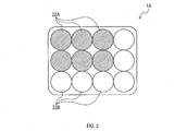
- the ultrasonic speakers 22A and 22B constitute a speaker group 1A configured as an array arrangement in which a plurality of ultrasonic speakers 22A and 22B are vertically and horizontally arranged as shown in FIG.
- the ultrasonic speakers 22A and 22B are disposed adjacent to each other, and output surfaces of sound waves are positioned on the same plane and configured in the same direction so as to output ultrasonic waves in the same direction. Ru.
- the speaker group 1A is configured as an array of twelve ultrasonic speakers 22A and 22B of three vertical and four horizontal.
- the ultrasonic speakers 22A and 22B constituting the speaker group 1A the upper left two vertical three and six horizontal six are ultrasonic speakers 22A which the ultrasonic amplifier 21A generates, and the remaining six are And the ultrasonic amplifier 21B is used as an ultrasonic speaker 22B.
- Such ultrasonic speakers 22A and 22B are disposed, for example, on the front of the vehicle 100 as a surface on the traveling direction side of the vehicle 100 as shown in FIG. Output
- the characteristics shown in FIG. 3 were obtained.
- FIG. 3 when only six ultrasonic speakers 22A are produced and when 12 ultrasonic speakers 22A and 22B are produced, the position where the intensity of the sound wave is a reference value is plotted. ing.
- the plot in FIG. 3 is the result of causing the ultrasonic speakers 22A and 22B to produce sounds of the same phase with an output of the same magnitude. Further, as the reference value, a value which is -6 dB with respect to the calculated output of the ultrasonic speakers 22A and 22B is adopted.
- the distance for causing the sound wave to reach only in the forward direction of the vehicle is changed while suppressing the sound wave from spreading in the left and right direction of the vehicle. Play an action.
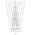
- FIG. 4 shows a model in which five ultrasonic speakers 22A and 22B are arranged in the horizontal direction, and three central ones of them are set as ultrasonic speakers 22A, and one each of both ends is set as ultrasonic speakers 22B. .
- the sound waves output from the respective ultrasonic speakers 22A and 22B are amplified by superposition, and the sound pressure increases in the region where the sound waves are superposed. In areas where sound waves are superimposed, sound waves are heard as louder, and the more the sound waves are superimposed, the farther the sound waves are heard.
- the number of ultrasonic speakers 22A and 22B is small, that is, if only ultrasonic speakers 22A are to be sounded, the number of overlapping sound waves is small, so the reach of the sound waves becomes relatively short. Specifically, when only the ultrasonic speaker 22A is made to sound, the sound wave is amplified by superposition in the area 51 of FIG. 4, and the sound pressure becomes large.
- the number of ultrasonic speakers 22A, 22B is large, that is, when the ultrasonic speakers 22A, 22B are made to sound, the number of sound waves to be superimposed is large, so the reach of the sound waves becomes relatively long.
- the ultrasonic speakers 22A and 22B are made to sound, the sound waves are amplified by superposition in the areas 51 and 52 of FIG. 4, and the sound pressure becomes large.
- the spread of sound hardly changes.
- the sound wave irradiation direction from the ultrasonic speakers 22A and 22B that is, the center in the forward direction of the vehicle is referred to as a sound axis
- many sound waves from the ultrasonic speakers 22A and 22B are superimposed near the sound axis. This is because the sound waves hardly overlap in the distant area.
- the region 52 where the sound wave is overlapped in the forward direction of the vehicle is widely spread, whereas in the left and right direction of the vehicle, the region 52 is spread only about the width of the ultrasonic speaker 22B. I understand.
- the ultrasonic wave output device 1 realizes the configuration of changing the arrival distance of the sound wave according to the traveling state of the vehicle by the following configuration using the characteristic of how the sound wave spreads by the speaker group 1A as described above.
- the processing unit 10 of the ultrasound output apparatus 1 is mainly configured of a known microcomputer having a CPU 11 and a semiconductor memory (hereinafter, memory 12) such as a RAM, a ROM, and a flash memory.
- memory 12 a semiconductor memory
- Various functions of the processing unit 10 are realized by the CPU 11 executing a program stored in a non-transitional tangible storage medium.
- the memory 12 corresponds to a non-transitional tangible storage medium storing a program.
- the non-transitional tangible recording medium has a meaning excluding the electromagnetic wave in the recording medium.
- the number of microcomputers constituting the processing unit 10 may be one or more.
- the processing unit 10 of the ultrasound output apparatus 1 includes a target recognition unit 16, an operation determination unit 17, and a signal generation unit 18 as a configuration of functions realized by the CPU 11 executing a program.
- the method for realizing these elements constituting the processing unit 10 is not limited to software, and part or all of the elements may be realized using one or more hardware.
- the electronic circuit may be realized by a digital circuit including many logic circuits, an analog circuit, or a combination thereof.
- the function of the target recognition unit 16 recognizes the position and the type of the target based on the information obtained by the object detection unit 31.
- a known technique such as a technique for specifying the type of an object from a plurality of distance measurement points or a technique for specifying a type of an object in a captured image from a captured image can be used.
- ultrasonic wave speakers 22A and 22B to be sounded are set and sounded by performing a wave judgment process described later.
- a pattern sound is generated by modulating the ultrasonic wave to a lower frequency, and is output as a sound having directivity.
- the reason that the function of the signal generation unit 18 generates directional sound is to limit the reach of the sound wave to the area that is dangerous to the subject, and it is difficult for the sound wave to spread to the area that is not dangerous. That is, the sound wave reaches a range that can be reached by the sound having the characteristic that the sound pressure rises sharply as it approaches the sound axis.
- the waveform of an ultrasonic wave having a constant amplitude (for example, 40 kHz) having a predetermined frequency (for example, 40 kHz) is amplitude modulated, and this waveform is shaped into a signal pattern indicating a predetermined alarm sound.
- the processing unit 10 acquires sensor data.
- the sensor data includes information obtained by the object detection unit 31 and the vehicle speed detection unit 32.
- the processing unit 10 recognizes the type of the target. This process is implemented using the function of the target recognition unit 16 described above. Specifically, it identifies that the target is a pedestrian, a bicycle, another vehicle or the like.
- the processing unit 10 determines whether a pedestrian has been detected. When it is determined that the pedestrian is not detected in S130, the processing unit 10 ends the operation determination process of FIG.
- the processing unit 10 proceeds to S140, and determines whether the vehicle speed V obtained from the vehicle speed detection unit 32 is equal to or more than the threshold value Vth.
- the vehicle speed V corresponds to a distance signal representing a signal according to the required arrival distance of the sound wave. That is, as the vehicle speed V increases, the braking distance increases, and it becomes necessary to widen the range in which the vehicle warns the vehicle ahead, so it can be said that the vehicle speed V indicates the required sound wave arrival distance.
- the processing unit 10 proceeds to S150, and sets the number of speaker buzzes to "many" meaning that the number of buzzes is large. That is, not only the ultrasonic speaker 22A but the ultrasonic speakers 22A and 22B are made to sound. As a result, the reach of the sound wave can be set further.
- the range which a vehicle warns can be made not to extend in the left-right direction of a vehicle.
- the vehicle speed V increases, it is difficult for the vehicle to make a sharp turn as the vehicle speed V increases so that the vehicle does not expand the warning range in the left and right direction of the vehicle. This is because it is not necessary to extend the range to be performed in the left and right direction of the vehicle.
- the processing unit 10 proceeds to S160, and sets the speaker buzzing number to "small" meaning that the buzzing number is small. That is, only the ultrasonic speaker 22A is made to sound.
- the reason for setting in this way is that when the vehicle speed V is small, the braking distance is short, so it is preferable to narrow the range in which the vehicle warns, in other words, to set the arrival distance of sound waves close.
- the ultrasound output apparatus 1 of the present disclosure includes a plurality of ultrasound speakers 22A and 22B and a processing unit 10.
- the plurality of ultrasonic speakers 22A and 22B are configured to output ultrasonic waves in the same direction.
- the processing unit 10 acquires a distance signal representing a signal according to the required sound wave arrival distance, or simply the vehicle speed, and generates ultrasonic speakers 22A and 22B to emit sound as the distance signal indicates or the vehicle speed increases. Is configured to set at least one sounding speaker representing the ultrasonic speaker 22A, 22B to be sounded out of the plurality of ultrasonic speakers 22A, 22B.
- the sound generation speaker is set to only the ultrasonic speaker 22A or both of the ultrasonic speakers 22A and 22B according to the distance signal or the vehicle speed.
- the processing unit 10 is configured to provide a sound wave signal for causing the sounding speaker to output an ultrasonic wave to at least one sounding speaker.
- an ultrasonic wave output device 1 it is possible to change the range in which the sound can be heard, at least the reach of the sound wave, with a simple configuration that changes the number of sound generation speakers.
- the processing unit 10 is configured to acquire the traveling speed of the vehicle equipped with the ultrasonic wave output device 1 as the vehicle equipped with the ultrasonic wave output device 1, and uses the traveling speed as the distance signal.
- the sound generation speakers are configured to be used so that the number of ultrasonic speakers 22A and 22B to be sounded as the traveling speed increases.
- the ultrasonic speakers 22A and 22B are increased as the traveling speed of the mounted vehicle increases, so that as the traveling speed of the mounted vehicle increases, the sound waves reach farther Can be configured.
- a sound wave may arrive only in the advancing direction of a vehicle, ie, the direction of a sound axis, and can suppress that sound spreads in the direction away from the sound axis, a sound leaks out of the advancing direction of a vehicle. Can be suppressed.
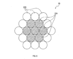
- the arrangement of the ultrasonic speakers 22A and 22B is arbitrary, but for example, as in the speaker group 1B shown in FIG.
- the ultrasonic speakers 22A and 22B may be disposed.
- the ultrasonic speakers 22A may be disposed at a more central position so as to generate a sound when setting the arrival distance of the sound waves shorter, and the ultrasonic speakers 22B may be arranged so as to surround the ultrasonic speakers 22A.
- the speaker group 1B since all of the ultrasonic speakers 22A to be sounded when setting the reaching distance of the sound wave short are arranged so that the surroundings are surrounded by the other ultrasonic speakers 22A and 22B, ultrasonic waves are generated.
- the speaker 22A can be vibrated more evenly.
- the speaker group 1B can be miniaturized.
- the processing unit 10 acquires the vehicle speed V as a signal according to the required sound wave arrival distance, but for example, it requests a signal related to the visibility of the surrounding illuminance, weather, etc. You may acquire as a signal according to the reach
- the processing unit 10 changes the required sound wave arrival distance in two steps, but is configured to change the required sound wave arrival distance in three or more steps. It is also good.
- the plurality of functions of one component in the above embodiment may be realized by a plurality of components, or one function of one component may be realized by a plurality of components . Also, a plurality of functions possessed by a plurality of components may be realized by one component, or one function realized by a plurality of components may be realized by one component. In addition, part of the configuration of the above embodiment may be omitted. Further, at least a part of the configuration of the above-described embodiment may be added to or replaced with the configuration of the other above-described embodiment.
- the ultrasonic speakers 22A and 22B in the above embodiment correspond to the sound generation speaker in the present disclosure
- the CPU 11 in the above embodiment corresponds to the arithmetic device in the present disclosure.
- the process of S110 among the processes which the process part 10 performs in the said embodiment is corresponded to the speed acquisition part in this indication
- the process of S140, S150, S160 in the said embodiment is in this indication. It corresponds to the pronunciation setting unit.
- the process of S150 and S160 in the said embodiment is corresponded to the signal provision part in this indication.
Landscapes
- Physics & Mathematics (AREA)
- Engineering & Computer Science (AREA)
- Acoustics & Sound (AREA)
- Health & Medical Sciences (AREA)
- Otolaryngology (AREA)
- Signal Processing (AREA)
- Mechanical Engineering (AREA)
- Circuit For Audible Band Transducer (AREA)
Priority Applications (1)
| Application Number | Priority Date | Filing Date | Title |
|---|---|---|---|
| DE112018004874.8T DE112018004874T5 (de) | 2017-09-06 | 2018-09-03 | Ultraschallwellen-Ausgabevorrichtung und Schallausgabe-Steuerverfahren |
Applications Claiming Priority (2)
| Application Number | Priority Date | Filing Date | Title |
|---|---|---|---|
| JP2017171091A JP2019047414A (ja) | 2017-09-06 | 2017-09-06 | 超音波出力装置、および発音制御方法 |
| JP2017-171091 | 2017-09-06 |
Publications (1)
| Publication Number | Publication Date |
|---|---|
| WO2019049827A1 true WO2019049827A1 (ja) | 2019-03-14 |
Family
ID=65634209
Family Applications (1)
| Application Number | Title | Priority Date | Filing Date |
|---|---|---|---|
| PCT/JP2018/032619 Ceased WO2019049827A1 (ja) | 2017-09-06 | 2018-09-03 | 超音波出力装置、および発音制御方法 |
Country Status (3)
| Country | Link |
|---|---|
| JP (1) | JP2019047414A (https=) |
| DE (1) | DE112018004874T5 (https=) |
| WO (1) | WO2019049827A1 (https=) |
Families Citing this family (1)
| Publication number | Priority date | Publication date | Assignee | Title |
|---|---|---|---|---|
| JP2025085191A (ja) * | 2023-11-24 | 2025-06-05 | アルプスアルパイン株式会社 | スピーカシステム |
Citations (4)
| Publication number | Priority date | Publication date | Assignee | Title |
|---|---|---|---|---|
| JP2011162073A (ja) * | 2010-02-10 | 2011-08-25 | Tabuchi Electric Co Ltd | 電動車両 |
| JP2013032103A (ja) * | 2011-08-02 | 2013-02-14 | Denso Corp | 車両存在報知装置 |
| JP2013095236A (ja) * | 2011-10-31 | 2013-05-20 | Denso Corp | 車両存在通報装置 |
| JP2017043197A (ja) * | 2015-08-26 | 2017-03-02 | 本田技研工業株式会社 | 車両の周囲に警報音を発出する警報装置 |
Family Cites Families (2)
| Publication number | Priority date | Publication date | Assignee | Title |
|---|---|---|---|---|
| JP2005286584A (ja) * | 2004-03-29 | 2005-10-13 | Mitsubishi Electric Engineering Co Ltd | パラメトリックスピーカ |
| JP6581931B2 (ja) | 2016-03-23 | 2019-09-25 | 株式会社小松製作所 | モータグレーダにおける制御方法およびモータグレーダ |
-
2017
- 2017-09-06 JP JP2017171091A patent/JP2019047414A/ja active Pending
-
2018
- 2018-09-03 DE DE112018004874.8T patent/DE112018004874T5/de not_active Withdrawn
- 2018-09-03 WO PCT/JP2018/032619 patent/WO2019049827A1/ja not_active Ceased
Patent Citations (4)
| Publication number | Priority date | Publication date | Assignee | Title |
|---|---|---|---|---|
| JP2011162073A (ja) * | 2010-02-10 | 2011-08-25 | Tabuchi Electric Co Ltd | 電動車両 |
| JP2013032103A (ja) * | 2011-08-02 | 2013-02-14 | Denso Corp | 車両存在報知装置 |
| JP2013095236A (ja) * | 2011-10-31 | 2013-05-20 | Denso Corp | 車両存在通報装置 |
| JP2017043197A (ja) * | 2015-08-26 | 2017-03-02 | 本田技研工業株式会社 | 車両の周囲に警報音を発出する警報装置 |
Also Published As
| Publication number | Publication date |
|---|---|
| JP2019047414A (ja) | 2019-03-22 |
| DE112018004874T5 (de) | 2020-06-10 |
Similar Documents
| Publication | Publication Date | Title |
|---|---|---|
| JP6853153B2 (ja) | 警報装置 | |
| US11317204B2 (en) | Methods, systems, and computer readable media for a phase array directed speaker | |
| US10694312B2 (en) | Dynamic augmentation of real-world sounds into a virtual reality sound mix | |
| JP2018517124A5 (https=) | ||
| CN104937660A (zh) | 用于生成声场的方法和系统 | |
| CN108515904A (zh) | 一种可控汽车喇叭系统及其工作方法 | |
| US10746872B2 (en) | System of tracking acoustic signal receivers | |
| CN117643074A (zh) | 用于载具的通透音频模式 | |
| JP2000236598A (ja) | 音像位置制御装置 | |
| WO2019049827A1 (ja) | 超音波出力装置、および発音制御方法 | |
| JP2008113190A (ja) | 可聴音指向性制御装置 | |
| JP2013015969A (ja) | 警報音生成装置および警報音生成方法 | |
| JP2019087057A (ja) | 情報提示システム、移動体、情報提示方法及びプログラム | |
| JP2007320472A (ja) | 自動車警告音発生装置 | |
| JP6329679B1 (ja) | オーディオコントローラ、超音波スピーカ、オーディオシステム、及びプログラム | |
| KR20210096879A (ko) | 차량 및 그 제어방법 | |
| WO2019021869A1 (ja) | 通知方法、通知装置、および発音装置 | |
| WO2020004460A1 (ja) | 超音波コントローラ、超音波スピーカ、及び、プログラム | |
| JP7095863B2 (ja) | 音響システム、音響処理方法、及びプログラム | |
| JP2022150801A (ja) | 音声出力システム | |
| JP2022011194A (ja) | 車両接近通報音制御装置 | |
| JP6330098B1 (ja) | オーディオコントローラ、プログラム、超音波スピーカ、音源装置 | |
| JP2022011195A (ja) | 車両接近通報音制御装置 | |
| JP2020088737A (ja) | スピーカ装置 | |
| JP7172876B2 (ja) | 車両用警告システム |
Legal Events
| Date | Code | Title | Description |
|---|---|---|---|
| 121 | Ep: the epo has been informed by wipo that ep was designated in this application |
Ref document number: 18852887 Country of ref document: EP Kind code of ref document: A1 |
|
| 122 | Ep: pct application non-entry in european phase |
Ref document number: 18852887 Country of ref document: EP Kind code of ref document: A1 |