WO2019049558A1 - カテーテル - Google Patents
カテーテル Download PDFInfo
- Publication number
- WO2019049558A1 WO2019049558A1 PCT/JP2018/028593 JP2018028593W WO2019049558A1 WO 2019049558 A1 WO2019049558 A1 WO 2019049558A1 JP 2018028593 W JP2018028593 W JP 2018028593W WO 2019049558 A1 WO2019049558 A1 WO 2019049558A1
- Authority
- WO
- WIPO (PCT)
- Prior art keywords
- chamber
- balloon
- catheter
- temperature
- sheet
- Prior art date
Links
Images


Classifications
-
- A—HUMAN NECESSITIES
- A61—MEDICAL OR VETERINARY SCIENCE; HYGIENE
- A61B—DIAGNOSIS; SURGERY; IDENTIFICATION
- A61B5/00—Measuring for diagnostic purposes; Identification of persons
- A61B5/68—Arrangements of detecting, measuring or recording means, e.g. sensors, in relation to patient
- A61B5/6846—Arrangements of detecting, measuring or recording means, e.g. sensors, in relation to patient specially adapted to be brought in contact with an internal body part, i.e. invasive
- A61B5/6847—Arrangements of detecting, measuring or recording means, e.g. sensors, in relation to patient specially adapted to be brought in contact with an internal body part, i.e. invasive mounted on an invasive device
- A61B5/6852—Catheters
- A61B5/6853—Catheters with a balloon
-
- A—HUMAN NECESSITIES
- A61—MEDICAL OR VETERINARY SCIENCE; HYGIENE
- A61B—DIAGNOSIS; SURGERY; IDENTIFICATION
- A61B18/00—Surgical instruments, devices or methods for transferring non-mechanical forms of energy to or from the body
- A61B18/04—Surgical instruments, devices or methods for transferring non-mechanical forms of energy to or from the body by heating
- A61B18/12—Surgical instruments, devices or methods for transferring non-mechanical forms of energy to or from the body by heating by passing a current through the tissue to be heated, e.g. high-frequency current
- A61B18/14—Probes or electrodes therefor
- A61B18/1492—Probes or electrodes therefor having a flexible, catheter-like structure, e.g. for heart ablation
-
- A—HUMAN NECESSITIES
- A61—MEDICAL OR VETERINARY SCIENCE; HYGIENE
- A61B—DIAGNOSIS; SURGERY; IDENTIFICATION
- A61B5/00—Measuring for diagnostic purposes; Identification of persons
- A61B5/01—Measuring temperature of body parts ; Diagnostic temperature sensing, e.g. for malignant or inflamed tissue
- A61B5/015—By temperature mapping of body part
-
- A—HUMAN NECESSITIES
- A61—MEDICAL OR VETERINARY SCIENCE; HYGIENE
- A61B—DIAGNOSIS; SURGERY; IDENTIFICATION
- A61B5/00—Measuring for diagnostic purposes; Identification of persons
- A61B5/68—Arrangements of detecting, measuring or recording means, e.g. sensors, in relation to patient
- A61B5/6846—Arrangements of detecting, measuring or recording means, e.g. sensors, in relation to patient specially adapted to be brought in contact with an internal body part, i.e. invasive
- A61B5/6867—Arrangements of detecting, measuring or recording means, e.g. sensors, in relation to patient specially adapted to be brought in contact with an internal body part, i.e. invasive specially adapted to be attached or implanted in a specific body part
- A61B5/687—Oesophagus
-
- A—HUMAN NECESSITIES
- A61—MEDICAL OR VETERINARY SCIENCE; HYGIENE
- A61B—DIAGNOSIS; SURGERY; IDENTIFICATION
- A61B90/00—Instruments, implements or accessories specially adapted for surgery or diagnosis and not covered by any of the groups A61B1/00 - A61B50/00, e.g. for luxation treatment or for protecting wound edges
- A61B90/04—Protection of tissue around surgical sites against effects of non-mechanical surgery, e.g. laser surgery
-
- A—HUMAN NECESSITIES
- A61—MEDICAL OR VETERINARY SCIENCE; HYGIENE
- A61M—DEVICES FOR INTRODUCING MEDIA INTO, OR ONTO, THE BODY; DEVICES FOR TRANSDUCING BODY MEDIA OR FOR TAKING MEDIA FROM THE BODY; DEVICES FOR PRODUCING OR ENDING SLEEP OR STUPOR
- A61M25/00—Catheters; Hollow probes
- A61M25/10—Balloon catheters
-
- A—HUMAN NECESSITIES
- A61—MEDICAL OR VETERINARY SCIENCE; HYGIENE
- A61B—DIAGNOSIS; SURGERY; IDENTIFICATION
- A61B18/00—Surgical instruments, devices or methods for transferring non-mechanical forms of energy to or from the body
- A61B2018/00315—Surgical instruments, devices or methods for transferring non-mechanical forms of energy to or from the body for treatment of particular body parts
- A61B2018/00345—Vascular system
- A61B2018/00351—Heart
-
- A—HUMAN NECESSITIES
- A61—MEDICAL OR VETERINARY SCIENCE; HYGIENE
- A61B—DIAGNOSIS; SURGERY; IDENTIFICATION
- A61B18/00—Surgical instruments, devices or methods for transferring non-mechanical forms of energy to or from the body
- A61B2018/00315—Surgical instruments, devices or methods for transferring non-mechanical forms of energy to or from the body for treatment of particular body parts
- A61B2018/00482—Digestive system
- A61B2018/00488—Esophagus
-
- A—HUMAN NECESSITIES
- A61—MEDICAL OR VETERINARY SCIENCE; HYGIENE
- A61B—DIAGNOSIS; SURGERY; IDENTIFICATION
- A61B18/00—Surgical instruments, devices or methods for transferring non-mechanical forms of energy to or from the body
- A61B2018/00571—Surgical instruments, devices or methods for transferring non-mechanical forms of energy to or from the body for achieving a particular surgical effect
- A61B2018/00577—Ablation
-
- A—HUMAN NECESSITIES
- A61—MEDICAL OR VETERINARY SCIENCE; HYGIENE
- A61B—DIAGNOSIS; SURGERY; IDENTIFICATION
- A61B18/00—Surgical instruments, devices or methods for transferring non-mechanical forms of energy to or from the body
- A61B2018/00636—Sensing and controlling the application of energy
- A61B2018/00773—Sensed parameters
- A61B2018/00791—Temperature
- A61B2018/00797—Temperature measured by multiple temperature sensors
-
- A—HUMAN NECESSITIES
- A61—MEDICAL OR VETERINARY SCIENCE; HYGIENE
- A61B—DIAGNOSIS; SURGERY; IDENTIFICATION
- A61B2562/00—Details of sensors; Constructional details of sensor housings or probes; Accessories for sensors
- A61B2562/04—Arrangements of multiple sensors of the same type
- A61B2562/043—Arrangements of multiple sensors of the same type in a linear array
-
- A—HUMAN NECESSITIES
- A61—MEDICAL OR VETERINARY SCIENCE; HYGIENE
- A61M—DEVICES FOR INTRODUCING MEDIA INTO, OR ONTO, THE BODY; DEVICES FOR TRANSDUCING BODY MEDIA OR FOR TAKING MEDIA FROM THE BODY; DEVICES FOR PRODUCING OR ENDING SLEEP OR STUPOR
- A61M2205/00—General characteristics of the apparatus
- A61M2205/33—Controlling, regulating or measuring
- A61M2205/3368—Temperature
-
- A—HUMAN NECESSITIES
- A61—MEDICAL OR VETERINARY SCIENCE; HYGIENE
- A61M—DEVICES FOR INTRODUCING MEDIA INTO, OR ONTO, THE BODY; DEVICES FOR TRANSDUCING BODY MEDIA OR FOR TAKING MEDIA FROM THE BODY; DEVICES FOR PRODUCING OR ENDING SLEEP OR STUPOR
- A61M2230/00—Measuring parameters of the user
- A61M2230/50—Temperature
Definitions
- the present invention relates to a catheter used to measure the internal temperature of hollow organs such as the esophagus.
- a catheter for measuring the temperature inside the esophagus As a catheter for measuring the temperature inside the esophagus, a plurality of ring electrodes (temperature measurement electrodes) mounted apart from each other at the tip of the catheter shaft and spots on the inner peripheral surfaces of each of the ring electrodes A plurality of temperature sensors (specifically, temperature measurement contacts of thermocouples) electrically connected to the ring electrode by welding, and lead wires of each of these temperature sensors (specifically, thermocouples).
- An electrode catheter (esophageal catheter) is provided, which comprises different kinds of metal wires).
- a plurality of side holes are formed in an array corresponding to the mounting position of the ring electrode in the tube wall of the tip of the catheter shaft constituting such an esophagus catheter, and the inner periphery of the ring electrode
- a lead connected to the surface spot-welded temperature sensor enters the lumen from a side hole formed in the tube wall of the catheter shaft, extends inside the lumen and the control handle and is connected to the connector .
- any temperature sensor of such an esophageal catheter reaches a predetermined temperature (for example, 43 ° C.)
- the ablation catheter is de-energized, thereby It is considered that overheating of the esophagus can be avoided.
- the esophagus is usually a flat elliptic tube, and the internal temperature of the esophagus during left atrial ablation is distributed not only in the longitudinal direction of the esophagus but also in the lateral direction thereof.
- a plurality of ring electrodes are disposed along the esophagus in the longitudinal direction. It is not possible to measure the temperature distribution in the width direction of the esophagus.
- the distal end portion 3 of the catheter shaft on which the ring-shaped electrode 1 is mounted is indwelled in the width direction of the esophagus E from the portion 5 heated by cauterization. In this case, the rise in the internal temperature of the esophagus E due to cauterization can not be accurately detected.
- a tip portion that can be deformed into a serpentine shape ie, a shape that meanders in the same plane is stored
- a shaft having a deformable section and a plurality of temperature sensors (ring electrodes) attached to the tip of the shaft see Patent Document 2 below.
- the temperature distribution in the width direction of the esophagus can not be accurately measured. That is, when the distal end portion of the meander-shaped shaft is placed in the esophagus, the plurality of temperature sensors are arranged in a plane (scattered in a substantially two-dimensional array), but the arrangement intervals of the temperature sensors are wide and adjacent The temperature sensors are spaced apart not only in the width direction of the esophagus but also in the length direction of the esophagus.
- the temperature of the inner circumferential surface of the ring electrode is regarded as the temperature inside the esophagus and measured by the temperature sensor
- the inner circumferential surface of the ring electrode since it takes a certain time for the inner circumferential surface of the ring electrode to heat up, it may not be possible to quickly detect the actual temperature change inside the esophagus.
- a temperature sensor is provided on the inner circumferential surface of the electrode portion opposite to the ablation side.
- JP-A-2010-505592 (claim 5) JP 2011-517417 gazette The Journal of Cardiovascular Electropfysiology Vol. 24, No. 9, September 2013
- the present invention has been made based on the above circumstances.
- the first object of the present invention is to provide a novel catheter for measuring the internal temperature of a hollow organ in the body.
- a second object of the present invention is to provide a catheter capable of grasping the temperature distribution inside the hollow organ in the body in a two-dimensional manner and reliably measuring the temperature of the site to be monitored.
- the third object of the present invention is to be able to planarly grasp the temperature distribution inside the esophagus which is a flat, elliptic tubular shape during left atrial ablation, and to ensure the temperature of the site heated by cauterization To provide a catheter that can be measured.
- a fourth object of the present invention is to provide a catheter for temperature measurement in which the esophagus is not expanded during left atrial ablation.
- a fifth object of the present invention is to provide a catheter capable of rapidly measuring a temperature change inside the esophagus as compared with a conventional temperature measuring catheter provided with a ring electrode.
- the catheter of the present invention is a catheter for measuring the internal temperature of a hollow organ in the body,
- a multi-lumen catheter shaft including a fluid flow lumen;
- a handle connected to the proximal side of the catheter shaft;
- a flat balloon connected to the distal end side of the catheter shaft and expanded by the fluid flowing through the flow lumen;
- a plurality of temperature sensors disposed flatly on one side of the balloon.
- the balloon is expanded (inflation) inside the hollow organ, and the temperature is measured by a plurality of temperature sensors disposed flatly on one side of the flat balloon.
- the temperature distribution inside the organ can be grasped in a planar manner, and the temperature of the site to be monitored can be reliably measured by any one or two or more of a plurality of planarly arranged temperature sensors be able to.
- the balloon is expanded inside the esophagus which is a flat elliptic tube, and the temperature is measured by a plurality of temperature sensors disposed flatly on one side of the flat balloon.
- the temperature is measured by a plurality of temperature sensors disposed flatly on one side of the flat balloon.
- the balloon which comprises this catheter is flat at the time of expansion, it can prevent that the esophagus inner wall is pressed in the direction in which the left atrium is located by one surface of the expanding balloon. Furthermore, by deflating the balloon during left atrial ablation, it is possible to completely prevent the inner wall of the esophagus from being pushed toward the left atrium by one side of the balloon. Furthermore, by deflating the balloon during left atrial ablation, the balloon can be completely prevented from expanding the esophagus in the transverse direction.
- a temperature sensor that constitutes this catheter is disposed on one side of the balloon, and a ring-shaped electrode (that heats up and cools down by absorbing and discharging caustic heat between the site where the temperature is to be measured and the temperature sensor) Since no temperature measuring electrode is interposed, the temperature change inside the esophagus can be measured more rapidly compared to a conventional temperature measuring catheter provided with such a ring-shaped electrode.
- the catheter according to the present invention comprises a plurality of the temperature sensors disposed along the longitudinal direction of the balloon (the direction coincident with the axial direction of the catheter shaft) on one side of the balloon.
- a plurality of temperature sensor groups are arranged along the width direction of the balloon.
- the temperature distribution in the longitudinal direction of the hollow organ can be measured by the plurality of temperature sensors belonging to each temperature sensor group. Further, the temperature distribution in the width direction of the hollow organ can be measured by a plurality of temperature sensors belonging to different temperature sensor groups and having the same or close position in the longitudinal direction of the balloon. As a result, the temperature distribution inside the hollow organ can be grasped in a planar manner.
- the balloon is formed by partially fusing the first sheet forming one surface and the second sheet forming the other surface, thereby forming a fluid storage space at the time of expansion. Be done,
- the plurality of temperature sensors are preferably embedded in the first sheet.
- the fluid containing space is formed in the non-fusion part of the first sheet and the second sheet, which is partitioned by the fusion part of the first sheet and the second sheet.
- these temperature sensors can be disposed flatly on one side of the balloon.
- the first sheet is a flat sheet
- the second sheet has a convex portion not fused to the first sheet, It is preferable that the accommodation space of the fluid at the time of expansion is formed of the said 1st sheet
- the catheter having such a configuration it is possible to flatten one surface side of the balloon on which the plurality of temperature sensors are disposed, and it is thereby possible to measure the temperature distribution with higher accuracy.
- the balloon serves as a fluid storage space at the time of expansion.
- a first chamber extending along an axial direction of the catheter shaft;
- a second chamber spaced apart on one side of the first chamber and extending parallel to the first chamber;
- a third chamber spaced apart on the other side of the first chamber and extending parallel to the first chamber;
- a communication passage for connecting the first chamber and the second chamber;
- a communication passage is formed to connect the first chamber and the third chamber, and
- the catheter shaft is formed with a tip opening or a side hole for supplying the fluid in the flow lumen to the first chamber.
- the fluid is supplied from the distal end opening or the side hole of the catheter shaft into the first chamber of the balloon, and the fluid supplied into the first chamber flows through the communication passage to the second chamber and It is delivered into the third chamber, which causes the balloon to expand.
- the first chamber, the second chamber, and the third chamber which are fluid storage spaces, extend in parallel with each other along the axial direction of the catheter shaft, and between the first chamber and the second chamber, A fusion-bonded portion of the first sheet and the second sheet is formed, and a fusion-bonded portion of the first sheet and the second sheet is also formed between the first chamber and the third chamber.
- the communication path extending to both sides from the first chamber is formed in a plurality along the axial direction of the catheter shaft, whereby flatness of the balloon at the time of expansion (in particular, a longitudinal sectional view (Flatness of the balloon) can be further improved.
- the communication passages extending from the first chamber to both sides are formed at equal intervals along the axial direction of the catheter shaft.
- the fluid containing space is formed in a lattice shape, and the fusion portion of the first sheet and the second sheet is arranged in a plane, so that the balloon is flat when expanded. It is possible to use the communication channel visually recognized on the X-ray image as a scale indicating the length while being particularly excellent.
- the distal end of the catheter shaft has a flexible portion and can be tip-biased.
- the catheter of the present invention is preferably used to measure the esophagus internal temperature in left atrial ablation.
- the temperature distribution inside the hollow organ in the body can be grasped in a planar manner, and the temperature of the site to be monitored can be reliably measured.
- the temperature distribution inside the flat, elliptic tubular esophagus can be grasped in a planar manner during left atrial ablation, and the temperature of the site heated by cauterization can be reliably measured. be able to.
- the temperature change inside the esophagus can be measured more quickly compared to a conventional temperature measuring catheter provided with a ring electrode.
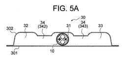
- FIG. 3 is a cross-sectional view taken along a line VA-VA in FIG.
- FIG. 3 is a cross-sectional view taken along a line VB-VB of FIG.
- VI section enlarged view sectional view of a catheter shaft
- FIG. 7 is a cross-sectional view taken along line VII-VII in FIG. 2 (a cross-sectional view of a catheter shaft). It is an explanatory view showing an example of arrangement of a temperature sensor in a balloon. It is a graph which shows the experimental result of the responsiveness of the temperature change in the catheter for temperature measurement. It is a front view which shows the front-end
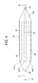
- the temperature measurement catheter 100 of the present embodiment shown in FIGS. 1 to 8 is a catheter for measuring the internal temperature of the esophagus during left atrial ablation.
- the temperature measuring catheter 100 includes a catheter shaft 10 having a distal flexible portion 10A, a control handle 20 connected to the proximal end side of the catheter shaft 10, and a balloon 30 connected to the distal end side of the catheter shaft 10.
- the temperature sensor 40 (401 to 424) disposed flatly on one side of the balloon 30, the lead wire 50 connected to each of the temperature sensors 40, and the flexible tip portion 10A of the catheter shaft 10 in the first direction
- a second operation wire 62 and a fluid injection tube 70 are provided.
- 81 is a tip
- 82 is an electrode for pacing the heart.
- the catheter shaft 10 constituting the temperature measuring catheter 100 is provided with a flow lumen (so-called expanded lumen) 11 for circulating a fluid for expanding the balloon 30, and a lead of the temperature sensor 40.
- the lead insertion lumen 12 for inserting the lead wire 85 of the wire 50 and the electrode 82, the wire insertion lumen 13 for inserting the first operation wire 61, and the wire insertion for inserting the second operation wire 62 A lumen 14 is formed.
- the fluid flowing through the flow lumen 11 is supplied to the flow lumen 11 from the fluid injection tube 70 via the inside of the control handle 20 and opens at the outer peripheral surface of the tip portion (tip flexible portion 10A) of the catheter shaft 10 It flows into the inside of the balloon 30 (a first chamber 31 described later) from the side hole 16.
- physiological saline can be exemplified as the fluid.
- the outer diameter of the catheter shaft 10 is usually 1.0 to 4.0 mm.
- the length of the catheter shaft 10 is usually 300 to 1,500 mm.
- thermoplastic resins such as polyamide, polyether polyamide, polyurethane, polyether block amide (PEBAX) (registered trademark) and nylon can be mentioned, and of these, PEBAX is preferable.
- a control handle 20 is connected to the proximal end side of the catheter shaft 10. Inside the control handle 20 constituting the temperature measurement catheter 100, a connector having a plurality of terminals is provided, and the terminals of the connector include the proximal end of the lead 50 of the temperature sensor 40 and the lead of the electrode 82 The proximal end of 85 is connected. Further, the control handle 20 is attached with a knob 25 for performing an operation of bending the distal end portion of the catheter shaft 10.
- a balloon 30 is connected to the distal end side of the catheter shaft 10.
- the balloon 30 constituting the temperature measurement catheter 100 is expanded by the fluid flowing through the flow lumen 11 of the catheter shaft 10, and has a flat shape even when expanded.
- a first sheet 301 forming one surface thereof and a second sheet 302 forming the other surface are partially fused.
- the first sheet 301 is a flat sheet
- the second sheet 302 has a convex portion which is not fused to the first sheet 301.
- the first sheet 301 and the convex portion of the second sheet 302 form a fluid containing space at the time of expansion.
- a first chamber 31 extending along the axial direction of the catheter shaft 10
- a second chamber 32 spaced apart on one side of the first chamber 31 and extending parallel to the first chamber 31, and a first chamber 31
- a communication passage 34 for communicating the first chamber 31 and the second chamber 32, and the first chamber 31 and the third chamber.
- a communication passage 34 (343) is formed to communicate with the communication passage 33.
- the communication passages 34 (the communication passages 342 and the communication passages 343) extending to both sides from the first chamber 31 are formed at equal intervals along the axial direction of the catheter shaft 10.
- the length of the balloon 30 (L30 shown in FIG. 2) is preferably 30 to 100 mm, and is 60 mm as a preferable example.
- the width (W30 shown in FIG. 5B) of the balloon 30 is determined in consideration of the width of the esophagus which is a flat elliptic tubular (the inner diameter (long diameter) of the elliptical tube), and the width (W30) is 10 to 30 mm. It is preferably 20 mm if a preferred example is shown.
- the thickness (H30 shown in FIG. 5B) of the balloon 30 at the time of expansion is determined in consideration of the inner diameter (short diameter) of the elliptical tube, and the thickness (H30) is preferably 1 to 5 mm, preferably One example is 2 mm.
- each of the first sheet 301 and the second sheet 302 constituting the balloon 30 is preferably 50 to 120 ⁇ m, and 80 ⁇ m as a preferred example.
- resin similar to the constituent material of the catheter shaft 10 can be used, and polyurethane is preferable among these.
- the balloon 30 is flat even at the time of expansion, and the ratio of thickness to width (H30 / W30) is preferably 0.1 to 0.17, and 0.1 (2 mm) is a preferable example. / 20 mm).
- distal end portion (distal end flexible portion 10A) of the catheter shaft 10 is inserted into the first chamber 31 and the fluid tightness of the first chamber 31 is secured. It extends from the tip of the first chamber 31 (balloon 30).
- the fluid flowing into the first chamber 31 from the side hole 16 opened on the outer peripheral surface of the distal end portion of the catheter shaft 10 flows through the communication passage 34 (342 and 343) and flows into the second chamber 32 and the third chamber 33.
- the fluid is filled in all the accommodation spaces (the first chamber 31, the second chamber 32, the third chamber 33 and the communication passage 34), whereby the balloon 30 is expanded.
- the balloon 30 fluid containing spaces (the first chamber 31, the second chamber 32, the third chamber 33 and the communication passage 34) are formed in a lattice shape, and the first sheet 301 and the second sheet 302 are melted. Since the wearing parts are arranged in a plane, the balloon 30 is particularly excellent in flatness when expanded. According to the balloon 30 excellent in flatness as described above, the flat shape of the balloon 30 can be surely matched with the flat elliptic tube of the esophagus at the time of expansion and contraction.
- the communication passages 34 (the communication passages 342 and the communication passages 343) extending on both sides from the first chamber 31 are formed at equal intervals along the axial direction of the catheter shaft 10, so that they are visually recognized on the X-ray image.
- the communication passage 34 can be used as a scale indicating the length.
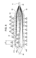
- temperature sensors 40 are disposed in a planar manner on one side of the balloon 30.
- the temperature sensor 40 (401 to 424) constituting the temperature measurement catheter 100 is, for example, a temperature measurement contact of a thermocouple, and is embedded in a first sheet 301 forming one surface of the balloon 30 (see FIG. 4).
- temperature sensor 40 embedded in the 1st sheet 301 is shown with a solid line, and illustration of temperature sensor 40 which appears in a transverse section of the 1st sheet 301 is omitted in Drawing 5A-Drawing 5C. ing.).
- the temperature sensor 40 (401 to 424) can be disposed on one side of the balloon 30, and the first sheet 301 in which the temperature sensor 40 is embedded is a flat sheet, so the temperature distribution with high accuracy Can be measured.
- the first temperature sensor is provided by the temperature sensors 40 (401 to 408) arranged at equal intervals along the longitudinal direction of the balloon 30 (axial direction of the catheter shaft 10).
- a second temperature sensor group 42G is constituted by the temperature sensors 40 (409 to 416) which constitute the group 41G and which are arranged at equal intervals along the same direction, and the temperature sensors 40 which are arranged at equal intervals along the same direction.
- the third temperature sensor group 43G is configured by (417 to 424).
- the distance between the temperature sensors 40 adjacent to each other in the longitudinal direction of the balloon 30 is preferably 3.5 to 11.7 mm, and a preferred example is 7.0 mm. is there.
- the first temperature sensor group 41G by the temperature sensors 401 to 408, the second temperature sensor group 42G by the temperature sensors 409 to 416, and the third temperature sensor group 43G by the temperature sensors 417 to 424 are equally spaced along the width direction of the balloon 30. Are arranged in
- the separation distance (d2 shown in FIG. 8) of the temperature sensor groups adjacent to each other in the width direction of the balloon 30 is preferably 3 to 13 mm, and 7.5 mm as a preferable example.
- the longitudinal position of the balloon 30 for each of the temperature sensors 40 (401 to 408) constituting the first temperature sensor group 41G and each of the temperature sensors 40 (417 to 424) constituting the third temperature sensor group 43G is the same.
- the longitudinal position of the balloon 30 for each of the temperature sensors 40 (409 to 416) constituting the second temperature sensor group 42G is the temperature sensor constituting the first temperature sensor group 41G or the third temperature sensor group 43G (D1 / 2) of the longitudinal position of the balloon 30 with respect to each of them.
- the temperature sensor 40 belonging to each of the first temperature sensor group 41G, the second temperature sensor group 42G and the third temperature sensor group 43G The longitudinal temperature distribution can be measured. Also, a plurality of temperature sensors 40 belonging to different temperature sensor groups and having the same or close position in the longitudinal direction of the balloon 30 (if an example is shown, the temperature sensor 405, the temperature sensor 412 and / or the temperature sensor The temperature distribution in the width direction of the esophagus can be measured by the temperature sensor 413). Then, by measuring the temperature distribution in the longitudinal direction and the width direction of the esophagus simultaneously, the temperature distribution in the esophagus can be grasped in a planar manner.
- the longitudinal position of the balloon 30 for each of the temperature sensors 40 constituting the second temperature sensor group 42G corresponds to the balloon for each of the temperature sensors constituting the first temperature sensor group 41G or the third temperature sensor group 43G.
- lead wires 50 are connected to the temperature sensors 40 (401 to 424), respectively.
- the lead wire 50 is made of, for example, different kinds of metal wires constituting a thermocouple that uses each of the temperature sensors 40 (401 to 424) as a temperature measurement contact.
- These lead wires 50 extend in the proximal direction while being embedded in the first sheet 301 constituting the balloon 30, and are formed on the outer peripheral surface of the catheter shaft 10 near the base end of the first sheet 301. It enters into lead penetration lumen 12 from the side hole which is not.
- the lead wires 50 embedded in the first sheet 301 are indicated by solid lines. Further, in FIG. 4 and FIGS. 5A to 5C, the illustration of the lead wire 50 is omitted.
- the lead wire 50 entering the lead insertion lumen 12 extends to the inside of the lead insertion lumen 12 and the control handle 20 together with the lead wire 85 of the electrode 82 for pacing, and is connected to the connector.
- the temperature measurement catheter 100 of the present embodiment can deflect its tip by pulling the first operation wire 61 and the second operation wire 62.
- each of the first operation wire 61 and the second operation wire 62 is fixed to the tip portion of the catheter shaft 10 (slightly proximal to the proximal end position of the balloon 30).
- the rear end of each of the first operation wire 61 and the second operation wire 62 is connected to the knob 25 of the control handle 20.
- the temperature inside the esophagus can be measured by the temperature measurement catheter 100 of the present embodiment as follows.
- the temperature measurement catheter 100 is inserted into the esophagus of the subject by a transnasal approach, and the balloon 30 mounted on the distal end side of the catheter shaft 10 is placed at the site where the temperature is to be monitored.
- the balloon 30 at the time of insertion is in a state of being wound (wrapped) around the distal end portion of the catheter shaft 10.
- a fluid (saline) is supplied from the fluid injection tube 70 to the flow lumen 11 of the catheter shaft 10.
- the fluid supplied to the flow lumen 11 flows into the first chamber 31 of the balloon 30 from the side hole 16 opened on the outer peripheral surface of the distal end portion of the catheter shaft 10 and flows through the communication passage 34 (communication passage 342 and communication passage 343). It also flows into the second chamber 32 and the third chamber 33.
- the fluid is stored in the first chamber 31, the second chamber 32, the third chamber 33, and the communication passage 34, so that the balloon 30 in the lapping state is expanded and expanded into a flat shape.
- the balloon 30 after expansion is placed so that the width direction thereof coincides with the width direction of the esophagus, and one side of the balloon 30 abuts or opposes the esophagus inner wall on the left atrium side.
- the fluid containing space first By discharging part or all of the fluid stored in the chamber 31, the second chamber 32, the third chamber 33 and the communication passage 34) and deflating the balloon 30, these states can be eliminated.
- the temperature inside the esophagus is simultaneously measured by the temperature sensor 40 (401 to 424) disposed on one side of the balloon 30, and the temperature distribution is grasped in a planar manner. Then, when the temperature inside the esophagus measured by any of the temperature sensors reaches a predetermined temperature (for example, 43 ° C.), the ablation catheter is deenergized and cauterization is stopped according to a conventional method.
- a predetermined temperature for example, 43 ° C.
- the flat oval is measured by measuring the temperature with the temperature sensor 40 (401 to 424) disposed flatly on one surface side of the balloon 30 during left atrial ablation.
- the temperature distribution inside the esophagus that is tubular can be grasped in a planar manner, and the temperature of the site heated up by cauterization (site where the temperature should be monitored) by any one or two or more temperature sensors 40 Can be measured reliably.
- the balloon 30 constituting the temperature measuring catheter 100 is flat even during dilation, one surface of the dilating balloon 30 presses the esophagus inner wall in the direction in which the left atrium is located during left atrial ablation. Can be prevented.
- by contracting the balloon 30 during left atrial ablation it is possible to reliably avoid that one surface of the balloon 30 presses the inner wall of the esophagus in the direction in which the left atrium is located.
- deflating the balloon 30 during left atrial ablation it is possible to reliably prevent the esophagus from being expanded by the balloon 30.
- the fluid containing space (the first chamber 31, the second chamber 32, the third chamber 33, and the communication passage 34) of the balloon 30 constituting the temperature measuring catheter 100 is formed in a lattice shape, and the first sheet 301 and the first Since the fusion portion with the two sheets 302 is arranged in a plane, the flatness of the balloon 30 at the time of expansion is particularly excellent.
- the communication passages 34 (the communication passages 342 and the communication passages 343) extending on both sides from the first chamber 31 are formed at equal intervals along the axial direction of the catheter shaft 10, so that they are visually recognized on the X-ray image.
- the communication passage 34 can be used as a scale indicating the length.
- the temperature sensor 40 (401 to 424) disposed on one surface side of the balloon 30 in a state of being embedded in the first sheet 301 Since there is no ring-shaped electrode (temperature measuring electrode) interposed between them, the temperature change inside the esophagus is rapidly measured in comparison with a conventional temperature measuring catheter provided with such a ring-shaped electrode. be able to.
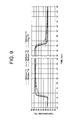
- FIG. 9 shows the experimental results of the responsiveness of the temperature change by the temperature measurement catheter 100 of the present embodiment together with the experimental results of the temperature change by the conventional temperature measurement catheter having a ring electrode.
- the mounting portion of the temperature sensor immersed in water at 26 ° C. is immersed in water at 37 ° C. to measure the responsiveness at the time of temperature rise, and the temperature is lowered again by immersing in water at 26 ° C. It is the graph which measured the responsiveness of the time.
- “Balloon: T1”, “Balloon: T2”, “Balloon: T3”, “Balloon: T4”, and “Balloon: T5” respectively indicate the temperature sensor 404 and the temperature sensor 405 shown in FIG.
- the temperature change measured by the temperature sensor 412, the temperature sensor 413, and the temperature sensor 420 is shown, and "Ring: T6" is the temperature change measured by the temperature measuring catheter provided with a ring-shaped electrode.
- the experiment was performed with the balloon 30, which is the mounting portion of the temperature sensor 40, contracted.
- the temperature measuring catheter 100 according to the present embodiment is more responsive to temperature change than the temperature measuring catheter provided with the ring-shaped electrode at rising and falling temperatures (rise and fall) It is understood that it is excellent in
- Second Embodiment 10 and 11 show the distal end portion of the temperature measurement catheter according to the second embodiment
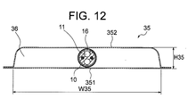
- FIG. 12 shows the XII-XII cross section of FIG.
- the same components as those of the temperature measurement catheter 100 according to the first embodiment are denoted by the same reference numerals.
- the temperature measurement catheter 200 of the present embodiment differs from the balloon 30 of the first embodiment in the configuration of the balloon 35 connected to the distal end side of the catheter shaft 10.
- the balloon 35 constituting the temperature measurement catheter 200 is expanded by the fluid flowing through the flow lumen of the catheter shaft 10, and has a flat shape even when expanded.
- a first sheet 351 forming one surface thereof and a second sheet 352 forming the other surface are partially fused to form a non-fused portion (a non-fused portion separated by the fused portion).
- the fusion part) forms a fluid containing space at the time of expansion.
- the first sheet 351 is a flat sheet
- the second sheet 352 has a convex portion which is not fused to the first sheet 351.
- the first sheet 351 and the convex portion of the second sheet 352 form a fluid accommodation space 36 at the time of expansion.
- the flat other surface of the balloon 35 is formed by the convex portion of the second sheet 352.
- the length of the balloon 35 (L35 shown in FIG. 10) is preferably 30 to 100 mm, and is 60 mm as a preferable example.
- the width (W35 shown in FIG. 12) of the balloon 35 is determined in consideration of the width of the esophagus which is a flat elliptic tubular (inner diameter (long diameter) of the elliptical tube), and the width (W35) is 10 to 30 mm. It is preferably 20 mm if a preferred example is shown.
- the thickness (H35 shown in FIG. 12) of the balloon 30 at the time of expansion is determined in consideration of the inner diameter (short diameter) of the elliptical tube, and the thickness (H35) is preferably 1 to 4 mm, One example is 2 mm.
- each of the first sheet 351 and the second sheet 352 constituting the balloon 35 is preferably 50 to 120 ⁇ m, and 80 ⁇ m as a preferable example.
- a constituent material of the balloon 35 the same resin as the constituent material of the catheter shaft 10 can be used, and of these, polyurethane is preferable.
- the balloon 35 is flat even at the time of expansion, and the ratio of thickness to width (H35 / W35) is preferably 0.1 to 0.17, and 0.1 (2 mm) is a preferable example. / 20 mm).
- the distal end portion (flexible distal portion 10A) of the catheter shaft 10 is inserted into the inside of the balloon 35 (the fluid containing space 36), and the liquid tightness of the containing space 36 is secured. In this state, it extends from the tip of the fluid containing space 36.
- the fluid flows into the fluid containing space 36 from the side hole 16 opened in the outer peripheral surface of the distal end portion of the catheter shaft 10, whereby the balloon 35 is expanded.
- the flat shape of the balloon 35 can be matched with the flat elliptic tube of the esophagus at the time of the expansion and after the contraction.
- the temperature sensor 40 is embedded in a first sheet 351 forming one surface of the balloon 35.
- the temperature sensor 40 can be disposed on one side of the balloon 35, and the first sheet 351 in which the temperature sensor 40 is embedded is a flat sheet, so that the temperature distribution can be measured with high accuracy. it can.
- the temperature sensor 40 embedded in the first sheet 351 is indicated by a solid line.
- seat 35 is abbreviate
- a lead wire is abbreviate
- the inside of the esophagus which is a flat elliptic tube is measured by measuring the temperature with the temperature sensor 40 disposed flatly on one side of the balloon 35 during left atrial ablation. Temperature distribution can be grasped on a plane, and the temperature of the portion (the portion whose temperature should be monitored) being heated by cauterization is reliably measured by any one or two or more temperature sensors 40 be able to.
- the balloon 35 constituting the temperature measuring catheter 200 is flat even during dilation, one surface of the dilating balloon 35 presses the esophagus inner wall in the direction in which the left atrium is located during left atrial ablation. Can be prevented.
- contracting the balloon 35 during the left atrial ablation operation it is possible to reliably avoid that the inner wall of the esophagus is pressed by the one surface of the balloon 35 in the direction in which the left atrium is located.
- deflating the balloon 35 during left atrial ablation it is possible to reliably prevent the esophagus from being expanded by the balloon 35.
- the temperature measurement catheter 200 of the present embodiment between the temperature sensor 40 disposed on one surface side of the balloon 35 in the state of being embedded in the first sheet 351, and the site where the temperature is to be measured. Since no ring-shaped electrode (temperature measuring electrode) is interposed, the temperature change inside the esophagus can be measured more rapidly compared to a conventional temperature measuring catheter provided with such a ring-shaped electrode.
- the distal end portion of the catheter shaft inserted into the first chamber of the balloon may be accommodated in the first chamber without extending from the distal end of the first chamber.
- the distal end portion of the catheter shaft inserted into the inside of the balloon (the fluid containing space) is housed inside the balloon without extending from the tip of the fluid containing space.
- the number of the communication passage connecting the first chamber and the second chamber and the communication passage connecting the first chamber and the third chamber may be one.
- the longitudinal position of the balloon with respect to the temperature sensor constituting the first temperature sensor group, the longitudinal direction of the balloon with respect to the temperature sensor constituting the second temperature sensor group, and the third temperature sensor group may coincide with one another.
Abstract
食道など体内の中空器官の内部の温度分布を平面的に把握することができ、監視すべき部位(焼灼によって昇温している部位)の温度を確実に測定することができる新規な温度測定用カテーテルを提供することを目的とする。本発明のカテーテルは、流体の流通ルーメン(11)を含むマルチルーメン構造のカテーテルシャフト(10)と、カテーテルシャフト(10)の基端側に接続されたハンドル(20)と、カテーテルシャフト(10)の先端側に接続され、流通ルーメン(11)を流通する流体により拡張し、拡張時において扁平なバルーン(30)と、バルーン(30)の一面側において平面的に配置された複数の温度センサ(40)とを備えている。
Description
本発明は食道などの体内中空器官の内部温度を測定するために使用するカテーテルに関する。
例えば、心房細動を治療するための左房アブレーション術において、左房の近くに位置する食道が過熱されて食道瘻などが起こることを防止するために、被術者の食道の内部に経鼻的アプローチによって温度測定用のカテーテルを挿入し、食道内部(内壁)の温度を監視することが提案されている(例えば、下記特許文献1参照)。
食道内部の温度を測定するためのカテーテルとして、カテーテルシャフトの先端部において互いに離間して装着された複数のリング状電極(温度測定用電極)と、これらリング状電極の各々の内周面にスポット溶接されることにより当該リング状電極に電気的に接続された複数の温度センサ(具体的は熱電対の測温接点)と、これらの温度センサの各々のリード線(具体的には、熱電対を構成する異種の金属線)とを備えてなる電極カテーテル(食道カテーテル)が提供されている。
このような食道カテーテルを構成するカテーテルシャフトの先端部の管壁には、リング状電極の装着位置に対応して複数の側孔(貫通孔)が配列形成されており、リング状電極の内周面にスポット溶接された温度センサに接続されたリード線は、カテーテルシャフトの管壁に形成された側孔からルーメンに進入し、当該ルーメンおよび制御ハンドルの内部に延在してコネクタに接続される。
左房アブレーション術中において、このような食道カテーテルの何れかの温度センサによって測定された食道内部の温度が所定の温度(例えば43℃)に到達すると、アブレーションカテーテルへの通電が遮断され、これにより、食道が過熱されることが回避できるとされる。
ところで、食道は、通常、扁平な楕円管状であり、左房アブレーション術中における食道の内部温度は食道の長さ方向だけでなく、その幅方向にも分布している。
しかしながら、特許文献1に記載されたような電極カテーテルを食道の内部に留置した場合、複数のリング状電極(温度測定用電極)が食道の長さ方向に沿って配置されることになるので、食道の幅方向の温度分布を測定することができない。
しかしながら、特許文献1に記載されたような電極カテーテルを食道の内部に留置した場合、複数のリング状電極(温度測定用電極)が食道の長さ方向に沿って配置されることになるので、食道の幅方向の温度分布を測定することができない。
このため、図13に示すように、リング状電極1が装着されているカテーテルシャフトの先端部分3が、焼灼により昇温している部位5から食道Eの幅方向に離間して留置されている場合には、焼灼による食道Eの内部温度の上昇を正確に検知することができなくなる。
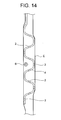
このような問題に対して、体内の組織又は器官の表面の温度を監視するための温度プローブとして、蛇行した形状に変形できる先端部分、すなわち、同一平面上で蛇行するような形状が記憶された変形可能区間を有するシャフトと、シャフトの先端部分に装着された複数の温度センサ(リング状電極)とを備えてなるものが提案されている(下記特許文献2参照)。
しかしながら、このような温度プローブによっても食道の幅方向の温度分布を精度よく測定することができない。
すなわち、蛇行形状のシャフトの先端部分を食道に留置したときに、複数の温度センサは平面的に配置される(略二次元配列に散らばる)ものの、温度センサの配置間隔は広く、また、隣り合う温度センサは、食道の幅方向だけでなく、食道の長さ方向にも離間している。
すなわち、蛇行形状のシャフトの先端部分を食道に留置したときに、複数の温度センサは平面的に配置される(略二次元配列に散らばる)ものの、温度センサの配置間隔は広く、また、隣り合う温度センサは、食道の幅方向だけでなく、食道の長さ方向にも離間している。
このため、図14に示すように、シャフトの先端部分4に装着されたリング状電極2を、焼灼により昇温している部位6に接近して位置させることができない場合があり、このような状態では、焼灼による食道Eの内部温度の上昇を正確に検知することができなくなる。
また、特許文献2に記載されたような温度プローブによっては、食道の内部に留置したシャフトの先端部分が蛇行形状に変形(復元)するときに、この先端部分が食道を拡張して左房後壁との接触面積を増大させる結果、食道が過熱されるリスクが高くなり、これによって合併症の増加を招くのではないかという指摘もなされている(下記非特許文献1参照)。
更に、リング状電極の内周面に温度センサがスポット溶接されている従来の温度測定用カテーテルにおいては、リング状電極の内周面温度を食道内部の温度とみなして温度センサにより測定しているが、リング状電極の内周面が昇温するまでには一定の時間を要するため、実際の食道内部の温度変化を迅速に検知できないことがある。
特に、焼灼側に面している電極部分と、焼灼側とは反対側の電極部分との間には温度差があるため、焼灼側とは反対側の電極部分の内周面に温度センサが位置している場合には、この温度センサによって測定された食道内部の温度が通電を遮断すべき温度に到達していなくても、焼灼側に面している電極部分が遮断すべき温度に到達し、食道が過熱状態となっていることも考えられ、そのような場合には、食道が損傷を受けるおそれがある。
本発明は以上のような事情に基いてなされたものである。
本発明の第1の目的は、体内の中空器官の内部温度を測定するための新規なカテーテルを提供することにある。
本発明の第2の目的は、体内の中空器官の内部の温度分布を平面的に把握することができ、監視すべき部位の温度を確実に測定することができるカテーテルを提供することにある。
本発明の第3の目的は、左房アブレーション術中において、扁平な楕円管状である食道の内部の温度分布を平面的に把握することができ、焼灼によって昇温している部位の温度を確実に測定することができるカテーテルを提供することにある。
本発明の第4の目的は、左房アブレーション術中において食道が拡張されることのない温度測定用のカテーテルを提供することにある。
本発明の第5の目的は、リング状電極を備えた従来の温度測定用カテーテルと比較して食道内部の温度変化を迅速に測定することができるカテーテルを提供することにある。
(1)本発明のカテーテルは、体内の中空器官の内部温度を測定するためのカテーテルであって、
流体の流通ルーメンを含むマルチルーメン構造のカテーテルシャフトと、
前記カテーテルシャフトの基端側に接続されたハンドルと、
前記カテーテルシャフトの先端側に接続され、前記流通ルーメンを流通する流体により拡張し、拡張時において扁平なバルーンと、
前記バルーンの一面側において平面的に配置された複数の温度センサと
を備えていることを特徴とする。
流体の流通ルーメンを含むマルチルーメン構造のカテーテルシャフトと、
前記カテーテルシャフトの基端側に接続されたハンドルと、
前記カテーテルシャフトの先端側に接続され、前記流通ルーメンを流通する流体により拡張し、拡張時において扁平なバルーンと、
前記バルーンの一面側において平面的に配置された複数の温度センサと
を備えていることを特徴とする。
このような構成のカテーテルによれば、中空器官の内部においてバルーンを拡張(インフレーション)させ、扁平なバルーンの一面側に平面的に配置されている複数の温度センサによって温度を測定することにより、中空器官の内部の温度分布を平面的に把握することができ、平面的に配置された複数の温度センサのうちの何れか1個または2個以上により、監視すべき部位の温度を確実に測定することができる。
また、このような構成のカテーテルによれば、扁平な楕円管状である食道の内部においてバルーンを拡張させ、扁平なバルーンの一面側に平面的に配置された複数の温度センサによって温度を測定することにより、食道内部の温度分布を平面的に把握すること(食道の長さ方向の温度分布および幅方向の温度分布を把握すること)ができ、平面的に配置された複数の温度センサのうちの何れか1個または2個以上により、焼灼によって昇温している部位(温度を監視すべき部位)の温度を確実に測定することができる。
また、このカテーテルを構成するバルーンが拡張時において扁平であるため、拡張しているバルーンの一面によって食道内壁が左房の位置する方向に押圧されることを防止することができる。
更に、左房アブレーション術中においてバルーンを収縮(デフレーション)させることにより、当該バルーンの一面によって食道内壁が左房の位置する方向に押圧されることを完全に回避することができる。
更に、左房アブレーション術中においてバルーンを収縮(デフレーション)させることにより、当該バルーンによって食道が幅方向に拡張されることも完全に回避することができる。
更に、左房アブレーション術中においてバルーンを収縮(デフレーション)させることにより、当該バルーンの一面によって食道内壁が左房の位置する方向に押圧されることを完全に回避することができる。
更に、左房アブレーション術中においてバルーンを収縮(デフレーション)させることにより、当該バルーンによって食道が幅方向に拡張されることも完全に回避することができる。
また、このカテーテルを構成する温度センサはバルーンの一面側に配置され、温度を測定すべき部位と当該温度センサとの間に、焼灼熱を吸収・放出して昇温・降温するリング状電極(温度測定用電極)が介在していないので、そのようなリング状電極を備えた従来の温度測定用カテーテルと比較して食道内部の温度変化を迅速に測定することができる。
(2)本発明のカテーテルにあっては、前記バルーンの一面側において、前記バルーンの長さ方向(前記カテーテルシャフトの軸方向に一致する方向)に沿って配置された複数の前記温度センサからなる温度センサ群が、前記バルーンの幅方向に沿って複数配列されていることが好ましい。
このような構成のカテーテルによれば、各々の温度センサ群に属する複数の温度センサにより、中空器官の長さ方向の温度分布を測定することができる。
また、互いに異なる温度センサ群に属し、かつ、バルーンの長さ方向位置が同一または近接している複数の温度センサにより、中空器官の幅方向の温度分布を測定することができる。
この結果、中空器官の内部の温度分布を平面的に把握することができる。
また、互いに異なる温度センサ群に属し、かつ、バルーンの長さ方向位置が同一または近接している複数の温度センサにより、中空器官の幅方向の温度分布を測定することができる。
この結果、中空器官の内部の温度分布を平面的に把握することができる。
(3)本発明のカテーテルにおいて、前記バルーンは、一面を形成する第1シートと他面を形成する第2シートとが部分的に融着されることで、拡張時における流体の収容空間が形成されてなり、
前記複数の温度センサは、前記第1シートに埋設されていることが好ましい。
前記複数の温度センサは、前記第1シートに埋設されていることが好ましい。
このような構成のカテーテルによれば、第1シートと第2シートとの融着部分により仕切られた、第1シートと第2シートとの非融着部分において、流体の収容空間を形成することができる。また、複数の温度センサを第1シートに埋設することによってこれらの温度センサを、バルーンの一面側において平面的に配置することができる。
(4)上記(3)のカテーテルにおいて、
前記第1シートは平坦なシートであり、
前記第2シートは、前記第1シートと融着されない凸部を有し、
前記第1シートと、前記第2シートの前記凸部とにより、拡張時における流体の収容空間が形成されていることが好ましい。
前記第1シートは平坦なシートであり、
前記第2シートは、前記第1シートと融着されない凸部を有し、
前記第1シートと、前記第2シートの前記凸部とにより、拡張時における流体の収容空間が形成されていることが好ましい。
このような構成のカテーテルによれば、複数の温度センサが配置されているバルーンの一面側を平坦にすることができ、これにより、より高い精度の温度分布を測定することができる。
(5)上記(4)のカテーテルにおいて、
前記バルーンには、拡張時における流体の収容空間として、
前記カテーテルシャフトの軸方向に沿って延びる第1室と、
前記第1室の一方側に離間して前記第1室と平行に延びる第2室と、
前記第1室の他方側に離間して前記第1室と平行に延びる第3室と、
前記第1室と前記第2室とを連通させる連通路と、
前記第1室と前記第3室とを連通させる連通路とが形成されており、
前記カテーテルシャフトの先端部分は、前記第1室に挿入または挿通され、
前記カテーテルシャフトには、前記流通ルーメンにおける流体を前記第1室に供給するための先端開口または側孔が形成されていることが好ましい。
前記バルーンには、拡張時における流体の収容空間として、
前記カテーテルシャフトの軸方向に沿って延びる第1室と、
前記第1室の一方側に離間して前記第1室と平行に延びる第2室と、
前記第1室の他方側に離間して前記第1室と平行に延びる第3室と、
前記第1室と前記第2室とを連通させる連通路と、
前記第1室と前記第3室とを連通させる連通路とが形成されており、
前記カテーテルシャフトの先端部分は、前記第1室に挿入または挿通され、
前記カテーテルシャフトには、前記流通ルーメンにおける流体を前記第1室に供給するための先端開口または側孔が形成されていることが好ましい。
このような構成のカテーテルによれば、カテーテルシャフトの先端開口または側孔からバルーンの第1室内に流体が供給され、第1室内に供給された流体は、連通路を流通して第2室内および第3室内に供給され、これにより、バルーンが拡張する。
ここに、流体の収容空間である第1室、第2室および第3室は、カテーテルシャフトの軸方向に沿って互いに平行に延びており、第1室と第2室との間には、第1シートと第2シートとの融着部分が形成され、第1室と第3室との間にも、第1シートと第2シートとの融着部分が形成されている。これにより、拡張時におけるバルーンの平坦性(特に、横断面視におけるバルーンの平坦性)を十分に確保することができる。
ここに、流体の収容空間である第1室、第2室および第3室は、カテーテルシャフトの軸方向に沿って互いに平行に延びており、第1室と第2室との間には、第1シートと第2シートとの融着部分が形成され、第1室と第3室との間にも、第1シートと第2シートとの融着部分が形成されている。これにより、拡張時におけるバルーンの平坦性(特に、横断面視におけるバルーンの平坦性)を十分に確保することができる。
(6)上記(5)のカテーテルにおいて、
前記第1室と、前記第2室および前記第3室とが連通するよう、前記第1室から両側(一方側および他方側)に延びる前記連通路が、前記カテーテルシャフトの軸方向に沿って複数形成されていることが好ましい。
前記第1室と、前記第2室および前記第3室とが連通するよう、前記第1室から両側(一方側および他方側)に延びる前記連通路が、前記カテーテルシャフトの軸方向に沿って複数形成されていることが好ましい。
このような構成のカテーテルによれば、第1室から両側に延びる連通路が、カテーテルシャフトの軸方向に沿って複数形成されていることにより、拡張時におけるバルーンの平坦性(特に、縦断面視におけるバルーンの平坦性)を更に向上させることができる。
(7)上記(6)のカテーテルにおいて、
前記第1室から両側に延びる前記連通路が前記カテーテルシャフトの軸方向に沿って等間隔で形成されていることが好ましい。
前記第1室から両側に延びる前記連通路が前記カテーテルシャフトの軸方向に沿って等間隔で形成されていることが好ましい。
このような構成のカテーテルによれば、流体の収容空間が格子状に形成され、第1シートと第2シートとの融着部分が平面的に配列されるので、拡張時におけるバルーンの平坦性に特に優れているとともに、X線画像上で視認される連通路を、長さを示す目盛として使用することが可能となる。
(8)本発明のカテーテルにおいて、前記カテーテルシャフトの先端に可撓部分を有し、先端偏向操作可能であることが好ましい。
(9)本発明のカテーテルは、左房アブレーション術における食道の内部温度を測定するために使用することが好ましい。
本発明のカテーテルによれば、体内の中空器官の内部の温度分布を平面的に把握することができ、監視すべき部位の温度を確実に測定することができる。
本発明のカテーテルによれば、左房アブレーション術中において、扁平な楕円管状の食道の内部の温度分布を平面的に把握することができ、焼灼によって昇温している部位の温度を確実に測定することができる。
本発明のカテーテルによれば、左房アブレーション術中において、扁平な楕円管状である食道が、温度センサの装着部であるバルーンによって拡張されることを回避することができる。更に、バルーンの一面によって食道内壁が左房の位置する方向に押圧されることも回避することができる。
本発明のカテーテルによれば、リング状電極を備えた従来の温度測定用カテーテルと比較して食道内部の温度変化を迅速に測定することができる。
本発明のカテーテルによれば、左房アブレーション術中において、扁平な楕円管状の食道の内部の温度分布を平面的に把握することができ、焼灼によって昇温している部位の温度を確実に測定することができる。
本発明のカテーテルによれば、左房アブレーション術中において、扁平な楕円管状である食道が、温度センサの装着部であるバルーンによって拡張されることを回避することができる。更に、バルーンの一面によって食道内壁が左房の位置する方向に押圧されることも回避することができる。
本発明のカテーテルによれば、リング状電極を備えた従来の温度測定用カテーテルと比較して食道内部の温度変化を迅速に測定することができる。
<第1実施形態>
以下、本発明のカテーテル(温度測定用カテーテル)の実施形態について図面を用いて説明する。
図1~図8に示す本実施形態の温度測定用カテーテル100は、左房アブレーション術中における食道の内部温度を測定するためのカテーテルである。
以下、本発明のカテーテル(温度測定用カテーテル)の実施形態について図面を用いて説明する。
図1~図8に示す本実施形態の温度測定用カテーテル100は、左房アブレーション術中における食道の内部温度を測定するためのカテーテルである。
この温度測定用カテーテル100は、先端可撓部分10Aを有するカテーテルシャフト10と、カテーテルシャフト10の基端側に接続された制御ハンドル20と、カテーテルシャフト10の先端側に接続されたバルーン30と、バルーン30の一面側において平面的に配置された温度センサ40(401~424)と、温度センサ40の各々に接続されたリード線50と、カテーテルシャフト10の先端可撓部分10Aを第1方向(図1において矢印Aで示す方向)に撓ませるための第1操作用ワイヤ61と、カテーテルシャフト10の先端可撓部分10Aを第2方向(図1において矢印Bで示す方向)に撓ませるための第2操作用ワイヤ62と、流体注入管70とを備えている。
図1~4において、81は先端チップ、82は心臓をペーシングするための電極である。
図1~4において、81は先端チップ、82は心臓をペーシングするための電極である。
図6および図7に示すように、温度測定用カテーテル100を構成するカテーテルシャフト10には、バルーン30を拡張させる流体を流通させるための流通ルーメン(いわゆる拡張ルーメン)11と、温度センサ40のリード線50および電極82のリード線85を挿通させるためのリード挿通ルーメン12と、第1操作用ワイヤ61を挿通させるためのワイヤ挿通ルーメン13と、第2操作用ワイヤ62を挿通させるためのワイヤ挿通ルーメン14とが形成されている。
流通ルーメン11を流通する流体は、流体注入管70から制御ハンドル20の内部を経由して当該流通ルーメン11に供給され、カテーテルシャフト10の先端部分(先端可撓部分10A)の外周面に開口する側孔16からバルーン30の内部(後述する第1室31)に流入される。
ここに、流体としては生理食塩水を例示することができる。
ここに、流体としては生理食塩水を例示することができる。
カテーテルシャフト10の外径は、通常1.0~4.0mmとされる。
また、カテーテルシャフト10の長さは、通常300~1500mmとされる。
カテーテルシャフト10の構成材料としては、ポリアミド、ポリエーテルポリアミド、ポリウレタン、ポリエーテルブロックアミド(PEBAX)(登録商標)およびナイロンなどの熱可塑性樹脂を挙げることができ、これらのうちPEBAXが好ましい。
また、カテーテルシャフト10の長さは、通常300~1500mmとされる。
カテーテルシャフト10の構成材料としては、ポリアミド、ポリエーテルポリアミド、ポリウレタン、ポリエーテルブロックアミド(PEBAX)(登録商標)およびナイロンなどの熱可塑性樹脂を挙げることができ、これらのうちPEBAXが好ましい。
カテーテルシャフト10の基端側には制御ハンドル20が接続されている。
温度測定用カテーテル100を構成する制御ハンドル20の内部には、複数の端子を備えたコネクタが設けられ、コネクタの端子には、温度センサ40のリード線50の基端、および電極82のリード線85の基端が接続されている。
また、制御ハンドル20には、カテーテルシャフト10の先端部分を曲げる操作を行うための摘み25が装着されている。
温度測定用カテーテル100を構成する制御ハンドル20の内部には、複数の端子を備えたコネクタが設けられ、コネクタの端子には、温度センサ40のリード線50の基端、および電極82のリード線85の基端が接続されている。
また、制御ハンドル20には、カテーテルシャフト10の先端部分を曲げる操作を行うための摘み25が装着されている。
カテーテルシャフト10の先端側にはバルーン30が接続されている。
温度測定用カテーテル100を構成するバルーン30は、カテーテルシャフト10の流通ルーメン11を流通する流体により拡張し、拡張時においても扁平な形状を有している。バルーン30は、その一面を形成する第1シート301と、他面を形成する第2シート302とが部分的に融着されてなる。
温度測定用カテーテル100を構成するバルーン30は、カテーテルシャフト10の流通ルーメン11を流通する流体により拡張し、拡張時においても扁平な形状を有している。バルーン30は、その一面を形成する第1シート301と、他面を形成する第2シート302とが部分的に融着されてなる。
図5A~図5Cに示すように、第1シート301は平坦なシートであり、第2シート302は、第1シート301と融着されない凸部を有している。
第1シート301と第2シート302の凸部とにより、拡張時における流体の収容空間が形成される。
具体的には、カテーテルシャフト10の軸方向に沿って延びる第1室31と、第1室31の一方側に離間して第1室31と平行に延びる第2室32と、第1室31の他方側に離間して第1室31と平行に延びる第3室33と、第1室31と第2室32とを連通させる連通路34(342)と、第1室31と第3室33とを連通させる連通路34(343)とが形成されている。
具体的には、カテーテルシャフト10の軸方向に沿って延びる第1室31と、第1室31の一方側に離間して第1室31と平行に延びる第2室32と、第1室31の他方側に離間して第1室31と平行に延びる第3室33と、第1室31と第2室32とを連通させる連通路34(342)と、第1室31と第3室33とを連通させる連通路34(343)とが形成されている。
図1および図2に示すように、第1室31から両側に延びる連通路34(連通路342および連通路343)は、カテーテルシャフト10の軸方向に沿って等間隔で形成されている。
バルーン30の長さ(図2に示すL30)としては30~100mmであることが好ましく、好適な一例を示せば60mmである。
バルーン30の幅(図5Bに示すW30)は、扁平な楕円管状である食道の幅(当該楕円管の内径(長径))を考慮して決定され、幅(W30)としては10~30mmであることが好ましく、好適な一例を示せば20mmである。
拡張時におけるバルーン30の厚さ(図5Bに示すH30)は、前記楕円管の内径(短径)を考慮して決定され、厚さ(H30)としては1~5mmであることが好ましく、好適な一例を示せば2mmである。
バルーン30を構成する第1シート301および第2シート302の厚さとしては、それぞれ50~120μmであることが好ましく、好適な一例を示せば80μmである。
バルーン30の構成材料としては、カテーテルシャフト10の構成材料と同様の樹脂を使用することができ、これらのうちポリウレタンが好ましい。
拡張時におけるバルーン30の厚さ(図5Bに示すH30)は、前記楕円管の内径(短径)を考慮して決定され、厚さ(H30)としては1~5mmであることが好ましく、好適な一例を示せば2mmである。
バルーン30を構成する第1シート301および第2シート302の厚さとしては、それぞれ50~120μmであることが好ましく、好適な一例を示せば80μmである。
バルーン30の構成材料としては、カテーテルシャフト10の構成材料と同様の樹脂を使用することができ、これらのうちポリウレタンが好ましい。
バルーン30は、拡張時においても扁平であり、その幅に対する厚さの比(H30/W30)としては0.1~0.17であることが好ましく、好適な一例を示せば0.1(2mm/20mm)である。
図1および図2に示すように、カテーテルシャフト10の先端部分(先端可撓部分10A)は、第1室31に挿通され、第1室31の液密性が確保されている状態で、当該第1室31(バルーン30)の先端から延び出している。
カテーテルシャフト10の先端部分の外周面に開口する側孔16から第1室31に流入される流体は、連通路34(342および343)を流通して第2室32および第3室33に流入し、すべての収容空間(第1室31、第2室32、第3室33および連通路34)に流体が充填されて、これにより、バルーン30が拡張する。
そして、バルーン30においては、流体の収容空間(第1室31、第2室32、第3室33および連通路34)が格子状に形成され、第1シート301と第2シート302との融着部分が平面的に配列されているので、当該バルーン30は、拡張時における平坦性が特に優れている。
このように平坦性に優れたバルーン30によれば、その拡張時および収縮後において、当該バルーン30の扁平な形状を、食道の扁平な楕円管状に確実に合致させることができる。
このように平坦性に優れたバルーン30によれば、その拡張時および収縮後において、当該バルーン30の扁平な形状を、食道の扁平な楕円管状に確実に合致させることができる。
また、第1室31から両側に延びる連通路34(連通路342および連通路343)が、カテーテルシャフト10の軸方向に沿って等間隔で形成されていることにより、X線画像上で視認される連通路34を、長さを示す目盛として使用することが可能となる。
図4および図8に示すように、バルーン30の一面側には、温度センサ40(401~424)が平面的に配置されている。
温度測定用カテーテル100を構成する温度センサ40(401~424)は、例えば、熱電対の測温接点からなり、バルーン30の一面を形成する第1シート301に埋設されている(なお、図4および図8では、第1シート301に埋設されている温度センサ40を実線で示している。また、図5A~図5Cでは、第1シート301の横断面に現れる温度センサ40の図示を省略している。)。
これにより、温度センサ40(401~424)をバルーン30の一面側に配置することができ、また、温度センサ40が埋設される第1シート301は平坦なシートであるので、高い精度の温度分布を測定することができる。
温度測定用カテーテル100を構成する温度センサ40(401~424)は、例えば、熱電対の測温接点からなり、バルーン30の一面を形成する第1シート301に埋設されている(なお、図4および図8では、第1シート301に埋設されている温度センサ40を実線で示している。また、図5A~図5Cでは、第1シート301の横断面に現れる温度センサ40の図示を省略している。)。
これにより、温度センサ40(401~424)をバルーン30の一面側に配置することができ、また、温度センサ40が埋設される第1シート301は平坦なシートであるので、高い精度の温度分布を測定することができる。
図8に示すように、バルーン30の一面側において、バルーン30の長さ方向(カテーテルシャフト10の軸方向)に沿って等間隔に配置された温度センサ40(401~408)により第1温度センサ群41Gが構成され、同方向に沿って等間隔に配置された温度センサ40(409~416)により第2温度センサ群42Gが構成され、同方向に沿って等間隔に配置された温度センサ40(417~424)により第3温度センサ群43Gが構成されている。
ここに、バルーン30の長さ方向に隣り合う温度センサ40の離間距離(図8に示すd1)としては3.5~11.7mmであることが好ましく、好適な一例を示せば7.0mmである。
温度センサ401~408による第1温度センサ群41G、温度センサ409~416による第2温度センサ群42G、温度センサ417~424による第3温度センサ群43Gは、バルーン30の幅方向に沿って等間隔に配列されている。
ここに、バルーン30の幅方向に隣り合う温度センサ群の離間距離(図8に示すd2)としては3~13mmであることが好ましく、好適な一例を示せば7.5mmである。
第1温度センサ群41Gを構成する温度センサ40(401~408)の各々についてのバルーン30の長さ方向位置と、第3温度センサ群43Gを構成する温度センサ40(417~424)の各々についてのバルーン30の長さ方向位置とは一致している。
他方、第2温度センサ群42Gを構成する温度センサ40(409~416)の各々についてのバルーン30の長さ方向位置は、第1温度センサ群41Gまたは第3温度センサ群43Gを構成する温度センサの各々についてのバルーン30の長さ方向位置より(d1/2)基端側にシフトしている。
他方、第2温度センサ群42Gを構成する温度センサ40(409~416)の各々についてのバルーン30の長さ方向位置は、第1温度センサ群41Gまたは第3温度センサ群43Gを構成する温度センサの各々についてのバルーン30の長さ方向位置より(d1/2)基端側にシフトしている。
図8に示したようにして温度センサ40を配置することによれば、第1温度センサ群41G、第2温度センサ群42Gおよび第3温度センサ群43Gの各々に属する温度センサ40により、食道の長さ方向の温度分布を測定することができる。
また、互いに異なる温度センサ群に属し、かつ、バルーン30の長さ方向位置が同一または近接している複数の温度センサ40(一例を示せば、温度センサ405と、温度センサ412および/または温度センサ413と、温度センサ421)により、食道の幅方向の温度分布を測定することができる。
そして、食道の長さ方向および幅方向の温度分布を同時に測定することにより、食道の内部の温度分布を平面的に把握することができる。
また、互いに異なる温度センサ群に属し、かつ、バルーン30の長さ方向位置が同一または近接している複数の温度センサ40(一例を示せば、温度センサ405と、温度センサ412および/または温度センサ413と、温度センサ421)により、食道の幅方向の温度分布を測定することができる。
そして、食道の長さ方向および幅方向の温度分布を同時に測定することにより、食道の内部の温度分布を平面的に把握することができる。
また、第2温度センサ群42Gを構成する温度センサ40の各々についてのバルーン30の長さ方向位置が、第1温度センサ群41Gまたは第3温度センサ群43Gを構成する温度センサの各々についてのバルーン30の長さ方向位置より(d1/2)基端側にシフトしていることにより、食道の長さ方向の温度分布をより高精度に測定することができる。
図8に示すように、温度センサ40(401~424)には、それぞれリード線50が接続されている。
リード線50は、例えば、温度センサ40(401~424)の各々を測温接点とする熱電対を構成する異種の金属線からなる。
これらのリード線50は、バルーン30を構成する第1シート301に埋設された状態で基端方向に延び、第1シート301の基端近傍において、カテーテルシャフト10の外周面に形成されている図示しない側孔からリード挿通ルーメン12に進入している。
なお、図8では、第1シート301に埋設されているリード線50を実線で示している。また、図4および図5A~図5Cでは、リード線50の図示を省略している。
リード挿通ルーメン12に進入したリード線50は、ペーシング用の電極82のリード線85とともに、当該リード挿通ルーメン12および制御ハンドル20の内部に延在してコネクタに接続される。
本実施形態の温度測定用カテーテル100は、第1操作用ワイヤ61および第2操作用ワイヤ62を引張操作することにより、その先端を偏向させることができる。
第1操作用ワイヤ61および第2操作用ワイヤ62の各々の先端はカテーテルシャフト10の先端部分(バルーン30の基端位置より僅かに基端側)に固定されている。
一方、第1操作用ワイヤ61および第2操作用ワイヤ62の各々の後端は制御ハンドル20の摘み25に接続されている。
一方、第1操作用ワイヤ61および第2操作用ワイヤ62の各々の後端は制御ハンドル20の摘み25に接続されている。
制御ハンドル20の摘み25を図1の矢印A1に示す方向に回転させて第1操作用ワイヤ61を引張操作することによりカテーテルシャフト10の先端部分(先端可撓部分10Aを第1方向(同図の矢印Aに示す方向)に曲げることができる。
また、制御ハンドル20の摘み25を図1の矢印B1に示す方向に回転させて第2操作用ワイヤ62を引張操作することによりカテーテルシャフト10の先端部分を第2方向(同図の矢印Bに示す方向)に曲げることができる。
また、制御ハンドル20の摘み25を図1の矢印B1に示す方向に回転させて第2操作用ワイヤ62を引張操作することによりカテーテルシャフト10の先端部分を第2方向(同図の矢印Bに示す方向)に曲げることができる。
左房アブレーション術中において、本実施形態の温度測定用カテーテル100により、下記のようにして食道の内部温度を測定することができる。
先ず、経鼻的アプローチによって温度測定用カテーテル100を被術者の食道の内部に挿入し、カテーテルシャフト10の先端側に装着されているバルーン30を、温度を監視すべき部位に留置する。ここに、挿入時におけるバルーン30はカテーテルシャフト10の先端部分に巻き付けられている(ラッピングされている)状態である。
次に、流体注入管70からカテーテルシャフト10の流通ルーメン11に流体(生理食塩水)を供給する。流通ルーメン11に供給された流体はカテーテルシャフト10の先端部分の外周面に開口する側孔16からバルーン30の第1室31に流入し、連通路34(連通路342および連通路343)を流通して第2室32および第3室33にも流入する。このようにして、第1室31、第2室32、第3室33および連通路34に流体が収容されることにより、ラッピング状態のバルーン30が展開して扁平状に拡張する。
拡張後におけるバルーン30は、その幅方向が食道の幅方向と一致し、バルーン30の
一面側が左房側の食道内壁に当接または対向するように留置される。
拡張後におけるバルーン30は、その幅方向が食道の幅方向と一致し、バルーン30の
一面側が左房側の食道内壁に当接または対向するように留置される。
ここに、拡張したバルーン30により食道が拡張されていたり、拡張したバルーン30の一面によって食道の内壁が左房の位置する方向に押圧されたりしている場合には、流体の収容空間(第1室31、第2室32、第3室33および連通路34)に収容されている流体の一部または全部を排出してバルーン30を収縮させることにより、これらの状態を解消することができる。
次に、バルーン30の一面側に配置された温度センサ40(401~424)によって食道内部の温度を同時に測定し、温度分布を平面的に把握する。
そして、何れかの温度センサによって測定された食道内部の温度が所定の温度(例えば43℃)に到達したときには、常法に従って、アブレーションカテーテルへの通電を遮断して焼灼を停止する。
そして、何れかの温度センサによって測定された食道内部の温度が所定の温度(例えば43℃)に到達したときには、常法に従って、アブレーションカテーテルへの通電を遮断して焼灼を停止する。
本実施形態の温度測定用カテーテル100によれば、左房アブレーション術中において、バルーン30の一面側において平面的に配置された温度センサ40(401~424)によって温度を測定することにより、扁平な楕円管状である食道内部の温度分布を平面的に把握することができ、何れか1個または2個以上の温度センサ40により、焼灼によって昇温している部位(温度を監視すべき部位)の温度を確実に測定することができる。
また、温度測定用カテーテル100を構成するバルーン30が拡張時においても扁平であるため、左房アブレーション術中において、拡張しているバルーン30の一面によって食道内壁が左房の位置する方向に押圧されることを防止することができる。
また、左房アブレーション術中において、バルーン30を収縮させることにより、当該バルーン30の一面によって食道の内壁が左房の位置する方向に押圧されることを確実に回避することができる。
また、左房アブレーション術中において、バルーン30を収縮させることにより、当該バルーン30によって食道が拡張されることを確実に回避することができる。
また、左房アブレーション術中において、バルーン30を収縮させることにより、当該バルーン30の一面によって食道の内壁が左房の位置する方向に押圧されることを確実に回避することができる。
また、左房アブレーション術中において、バルーン30を収縮させることにより、当該バルーン30によって食道が拡張されることを確実に回避することができる。
また、温度測定用カテーテル100を構成するバルーン30の流体の収容空間(第1室31、第2室32、第3室33および連通路34)が格子状に形成され、第1シート301と第2シート302との融着部分が平面的に配列されているので、拡張時におけるバルーン30の平坦性に特に優れている。
また、第1室31から両側に延びる連通路34(連通路342および連通路343)が、カテーテルシャフト10の軸方向に沿って等間隔で形成されていることにより、X線画像上で視認される連通路34を、長さを示す目盛として使用することができる。
更に、本実施形態の温度測定用カテーテル100においては、第1シート301に埋設された状態でバルーン30の一面側に配置されている温度センサ40(401~424)と、温度を測定すべき部位との間に、リング状電極(温度測定用電極)が介在していないので、そのようなリング状電極を備えた従来の温度測定用カテーテルと比較して食道内部の温度変化を迅速に測定することができる。
図9は、本実施形態の温度測定用カテーテル100による温度変化の応答性の実験結果をリング状電極を備えた従来の温度測定用カテーテルによる温度変化の応答性の実験結果とともに示している。
具体的には、26℃の水中に浸漬している温度センサの装着部を、37℃の水中に浸漬して昇温時の応答性を測定し、再度、26℃の水中に浸漬して降温時の応答性を測定したグラフである。
同図において、「Balloon:T1」、「Balloon:T2」、「Balloon:T3」、「Balloon:T4」、「Balloon:T5」は、それぞれ、図8に示した温度センサ404、温度センサ405、温度センサ412、温度センサ413、温度センサ420により測定された温度変化を示し、「Ring:T6」は、リング状電極を備えた温度測定用カテーテルにより測定された温度変化を示している。
なお、温度測定用カテーテル100では、温度センサ40の装着部であるバルーン30を収縮状態で実験を行った。
同図に示すように、昇温時および降温時の何れにおいても本実施形態の温度測定用カテーテル100は、リング状電極を備えた温度測定用カテーテルよりも温度変化の応答性(立ち上がりおよび立ち下がり)に優れていることが理解される。
<第2実施形態>
図10および図11は、第2実施形態に係る温度測定用カテーテルの先端部を示し、図12は、図10のXII-XII断面を示している。図10~図12において、第1実施形態に係る温度測定用カテーテル100と同一の構成要素には、同一の符号を用いている。
図10および図11は、第2実施形態に係る温度測定用カテーテルの先端部を示し、図12は、図10のXII-XII断面を示している。図10~図12において、第1実施形態に係る温度測定用カテーテル100と同一の構成要素には、同一の符号を用いている。
本実施形態の温度測定用カテーテル200は、カテーテルシャフト10の先端側に接続されたバルーン35の構成が、第1実施形態におけるバルーン30と異なっている。
温度測定用カテーテル200を構成するバルーン35は、カテーテルシャフト10の流通ルーメンを流通する流体により拡張し、拡張時においても扁平な形状を有している。
バルーン35は、その一面を形成する第1シート351と、他面を形成する第2シート352とが部分的に融着されてなり、融着されていない部分(融着部分により仕切られた非融着部分)により、拡張時における流体の収容空間が形成される。
バルーン35は、その一面を形成する第1シート351と、他面を形成する第2シート352とが部分的に融着されてなり、融着されていない部分(融着部分により仕切られた非融着部分)により、拡張時における流体の収容空間が形成される。
図12に示すように、第1シート351は平坦なシートであり、第2シート352は、第1シート351と融着されない凸部を有している。
第1シート351と第2シート352の凸部とにより、拡張時における流体の収容空間36が形成される。また、第2シート352の凸部により、バルーン35の平坦な他面が形成される。
第1シート351と第2シート352の凸部とにより、拡張時における流体の収容空間36が形成される。また、第2シート352の凸部により、バルーン35の平坦な他面が形成される。
バルーン35の長さ(図10に示すL35)としては30~100mmであることが好ましく、好適な一例を示せば60mmである。
バルーン35の幅(図12に示すW35)は、扁平な楕円管状である食道の幅(当該楕円管の内径(長径))を考慮して決定され、幅(W35)としては10~30mmであることが好ましく、好適な一例を示せば20mmである。
拡張時におけるバルーン30の厚さ(図12に示すH35)は、前記楕円管の内径(短径)を考慮して決定され、厚さ(H35)としては1~4mmであることが好ましく、好適な一例を示せば2mmである。
バルーン35を構成する第1シート351および第2シート352の厚さとしては、それぞれ50~120μmであることが好ましく、好適な一例を示せば80μmである。
バルーン35の構成材料としては、カテーテルシャフト10の構成材料と同様の樹脂を使用することができ、これらのうちポリウレタンが好ましい。
拡張時におけるバルーン30の厚さ(図12に示すH35)は、前記楕円管の内径(短径)を考慮して決定され、厚さ(H35)としては1~4mmであることが好ましく、好適な一例を示せば2mmである。
バルーン35を構成する第1シート351および第2シート352の厚さとしては、それぞれ50~120μmであることが好ましく、好適な一例を示せば80μmである。
バルーン35の構成材料としては、カテーテルシャフト10の構成材料と同様の樹脂を使用することができ、これらのうちポリウレタンが好ましい。
バルーン35は、拡張時においても扁平であり、その幅に対する厚さの比(H35/W35)としては0.1~0.17であることが好ましく、好適な一例を示せば0.1(2mm/20mm)である。
図10および図11に示すように、カテーテルシャフト10の先端部分(先端可撓部分10A)は、バルーン35の内部(流体の収容空間36)に挿通され、収容空間36の液密性が確保されている状態で、当該流体の収容空間36の先端から延び出している。
カテーテルシャフト10の先端部分の外周面に開口する側孔16から流体の収容空間36に流入し、これにより、バルーン35が拡張する。
拡張時においても扁平であるバルーン35によれば、その拡張時および収縮後において、当該バルーン35の扁平な形状を食道の扁平な楕円管状と合致させることができる。
図11に示すように、バルーン35の一面側には、24個の温度センサ40が平面的に配置されている。
温度センサ40は、バルーン35の一面を形成する第1シート351に埋設されている。
これにより、温度センサ40をバルーン35の一面側に配置することができ、また、温度センサ40が埋設される第1シート351は平坦なシートであるので、高い精度の温度分布を測定することができる。
なお、図11では、第1シート351に埋設されている温度センサ40を実線で示している。また、図12では、第1シート351の横断面に現れる温度センサ40の図示を省略している。また、図11および図12では、リード線の図示を省略している。
温度センサ40は、バルーン35の一面を形成する第1シート351に埋設されている。
これにより、温度センサ40をバルーン35の一面側に配置することができ、また、温度センサ40が埋設される第1シート351は平坦なシートであるので、高い精度の温度分布を測定することができる。
なお、図11では、第1シート351に埋設されている温度センサ40を実線で示している。また、図12では、第1シート351の横断面に現れる温度センサ40の図示を省略している。また、図11および図12では、リード線の図示を省略している。
本実施形態の温度測定用カテーテル200によれば、左房アブレーション術中において、バルーン35の一面側において平面的に配置された温度センサ40によって温度を測定することにより、扁平な楕円管状である食道内部の温度分布を平面的に把握することができ、何れか1個または2個以上の温度センサ40により、焼灼によって昇温している部位(温度を監視すべき部位)の温度を確実に測定することができる。
また、温度測定用カテーテル200を構成するバルーン35が拡張時においても扁平であるため、左房アブレーション術中において、拡張しているバルーン35の一面によって食道内壁が左房の位置する方向に押圧されることを防止することができる。
また、左房アブレーション術中において、バルーン35を収縮させることにより、当該バルーン35の一面によって食道の内壁が左房の位置する方向に押圧されることを確実に回避することができる。
また、左房アブレーション術中において、バルーン35を収縮させることにより、当該バルーン35によって食道が拡張されることを確実に回避することができる。
また、左房アブレーション術中において、バルーン35を収縮させることにより、当該バルーン35の一面によって食道の内壁が左房の位置する方向に押圧されることを確実に回避することができる。
また、左房アブレーション術中において、バルーン35を収縮させることにより、当該バルーン35によって食道が拡張されることを確実に回避することができる。
更に、本実施形態の温度測定用カテーテル200においては、第1シート351に埋設された状態でバルーン35の一面側に配置されている温度センサ40と、温度を測定すべき部位との間に、リング状電極(温度測定用電極)が介在していないので、そのようなリング状電極を備えた従来の温度測定用カテーテルと比較して食道内部の温度変化を迅速に測定することができる。
以上、本発明の一実施形態について説明したが、本発明はこれらの実施形態に限定されるものではなく、種々の変更が可能である。
例えば、第1実施形態において、バルーンの第1室に挿入されたカテーテルシャフトの先端部分を、第1室の先端から延び出させることなく、第1室内に収容した状態としてもよい。同様に、第2実施形態において、バルーンの内部(流体の収容空間)に挿入されたたカテーテルシャフトの先端部分を、流体の収容空間の先端から延び出させることなく、バルーンの内部に収容した状態としてもよい。
また、第1実施形態において、第1室と第2室とを連通させる連通路と、第1室と第3室とを連通させる連通路とは、それぞれ1つであってもよい。
また、第1温度センサ群を構成する温度センサについてのバルーンの長さ方向位置と、第2温度センサ群を構成する温度センサについてのバルーンの長さ方向位置と、第3温度センサ群を構成する温度センサについてのバルーンの長さ方向位置とが互いに一致していてもよい。
また、第1実施形態において、第1室と第2室とを連通させる連通路と、第1室と第3室とを連通させる連通路とは、それぞれ1つであってもよい。
また、第1温度センサ群を構成する温度センサについてのバルーンの長さ方向位置と、第2温度センサ群を構成する温度センサについてのバルーンの長さ方向位置と、第3温度センサ群を構成する温度センサについてのバルーンの長さ方向位置とが互いに一致していてもよい。
100 温度測定用カテーテル
10 カテーテルシャフト
11 流通ルーメン
12 リード挿通ルーメン
13,14 ワイヤ挿通ルーメン
16 側孔
20 制御ハンドル
25 摘み
30 バルーン
301 第1シート
302 第2シート
31 第1室
32 第2室
33 第3室
34(342,343) 連通路
40(401~424) 温度センサ
41G 第1温度センサ群
42G 第2温度センサ群
43G 第3温度センサ群
50 温度センサのリード線
61 第1操作用ワイヤ
62 第2操作用ワイヤ
70 流体注入管
81 先端チップ
82 電極
85 電極のリード線
200 温度測定用カテーテル
35 バルーン
351 第1シート
352 第2シート
36 流体の収容空間
Claims (9)
- 体内の中空器官の内部温度を測定するためのカテーテルであって、
流体の流通ルーメンを含むマルチルーメン構造のカテーテルシャフトと、
前記カテーテルシャフトの基端側に接続されたハンドルと、
前記カテーテルシャフトの先端側に接続され、前記流通ルーメンを流通する流体により拡張し、拡張時において扁平なバルーンと、
前記バルーンの一面側において平面的に配置された複数の温度センサと
を備えていることを特徴とするカテーテル。 - 前記バルーンの一面側において、前記バルーンの長さ方向に沿って配置された複数の前記温度センサからなる温度センサ群が前記バルーンの幅方向に沿って複数配列されていることを特徴とする請求項1に記載のカテーテル。
- 前記バルーンは、一面を形成する第1シートと他面を形成する第2シートとが部分的に融着されることで、拡張時における流体の収容空間が形成されてなり、
前記複数の温度センサは、前記第1シートに埋設されていることを特徴とする請求項1または2に記載のカテーテル。 - 前記第1シートは平坦なシートであり、
前記第2シートは、前記第1シートと融着されない凸部を有し、
前記第1シートと、前記第2シートの前記凸部とにより、拡張時における流体の収容空間が形成されていることを特徴とする請求項3に記載のカテーテル。 - 前記バルーンには、拡張時における流体の収容空間として、
前記カテーテルシャフトの軸方向に沿って延びる第1室と、
前記第1室の一方側に離間して前記第1室と平行に延びる第2室と、
前記第1室の他方側に離間して前記第1室と平行に延びる第3室と、
前記第1室と前記第2室とを連通させる連通路と、
前記第1室と前記第3室とを連通させる連通路とが形成されており、
前記カテーテルシャフトの先端部分は、前記第1室に挿入または挿通され、
前記カテーテルシャフトには、前記流通ルーメンにおける流体を前記第1室に供給するための先端開口または側孔が形成されていることを特徴とする請求項4に記載のカテーテル。 - 前記第1室と、前記第2室および前記第3室とが連通するよう、前記第1室から両側に延びる前記連通路が、前記カテーテルシャフトの軸方向に沿って複数形成されていることを特徴とする請求項5に記載のカテーテル。
- 前記第1室から両側に延びる前記連通路が前記カテーテルシャフトの軸方向に沿って等間隔で形成されていることを特徴とする請求項6に記載のカテーテル。
- 前記カテーテルシャフトの先端に可撓部分を有し、先端偏向操作可能であることを特徴とする請求項1~7の何れかに記載のカテーテル。
- 左房アブレーション術における食道の内部温度を測定するために使用することを特徴とする請求項1~8の何れかに記載のカテーテル。
Priority Applications (3)
| Application Number | Priority Date | Filing Date | Title |
|---|---|---|---|
| KR1020207004640A KR102282198B1 (ko) | 2017-09-06 | 2018-07-31 | 카테터 |
| CN201880027150.8A CN110545878A (zh) | 2017-09-06 | 2018-07-31 | 导管 |
| EP18854968.7A EP3679976A4 (en) | 2017-09-06 | 2018-07-31 | CATHETER |
Applications Claiming Priority (2)
| Application Number | Priority Date | Filing Date | Title |
|---|---|---|---|
| JP2017-170895 | 2017-09-06 | ||
| JP2017170895A JP6755630B2 (ja) | 2017-09-06 | 2017-09-06 | カテーテル |
Publications (1)
| Publication Number | Publication Date |
|---|---|
| WO2019049558A1 true WO2019049558A1 (ja) | 2019-03-14 |
Family
ID=65633897
Family Applications (1)
| Application Number | Title | Priority Date | Filing Date |
|---|---|---|---|
| PCT/JP2018/028593 WO2019049558A1 (ja) | 2017-09-06 | 2018-07-31 | カテーテル |
Country Status (5)
| Country | Link |
|---|---|
| EP (1) | EP3679976A4 (ja) |
| JP (1) | JP6755630B2 (ja) |
| KR (1) | KR102282198B1 (ja) |
| CN (1) | CN110545878A (ja) |
| WO (1) | WO2019049558A1 (ja) |
Cited By (2)
| Publication number | Priority date | Publication date | Assignee | Title |
|---|---|---|---|---|
| JPWO2021186523A1 (ja) * | 2020-03-17 | 2021-09-23 | ||
| WO2021186522A1 (ja) * | 2020-03-17 | 2021-09-23 | 日本ライフライン株式会社 | カテーテル用器具およびカテーテル |
Families Citing this family (5)
| Publication number | Priority date | Publication date | Assignee | Title |
|---|---|---|---|---|
| WO2021149215A1 (ja) * | 2020-01-23 | 2021-07-29 | 日本ライフライン株式会社 | カテーテル |
| CN111529900A (zh) * | 2020-05-14 | 2020-08-14 | 甘肃省第二人民医院 | 一种可视可调转向气囊导尿管 |
| JPWO2022176013A1 (ja) * | 2021-02-16 | 2022-08-25 | ||
| CN113229786B (zh) * | 2021-05-17 | 2023-03-24 | 河北地质大学 | 一种术中经内镜自膨胀式硅胶心房食道瘘测温装置 |
| CN113952596A (zh) * | 2021-10-28 | 2022-01-21 | 武汉威润八方医疗科技有限公司 | 一种智能化无线导尿管 |
Citations (7)
| Publication number | Priority date | Publication date | Assignee | Title |
|---|---|---|---|---|
| JP2001515772A (ja) * | 1997-09-06 | 2001-09-25 | フェルケル、ヴォフラム | バルーン・カテーテル |
| JP2010505592A (ja) | 2006-10-10 | 2010-02-25 | バイオセンス・ウエブスター・インコーポレーテツド | 食道マッピングカテーテル |
| JP2010528815A (ja) * | 2007-06-14 | 2010-08-26 | ボストン サイエンティフィック サイムド,インコーポレイテッド | クライオジェニック・バルーン・アブレーション器具及びシステム |
| JP2011517417A (ja) | 2008-03-18 | 2011-06-09 | サーカ・サイエンティフィック,エルエルシー | 大表面積温度感知装置 |
| JP2015042312A (ja) * | 2008-04-16 | 2015-03-05 | アビオメド インコーポレイテッド | 人工弁のような管腔内プロテーゼを埋め込む方法および装置 |
| JP2015173681A (ja) * | 2014-03-13 | 2015-10-05 | 日本ライフライン株式会社 | 温度センサ付電極カテーテル |
| WO2016164420A1 (en) * | 2015-04-06 | 2016-10-13 | C.R. Bard, Inc. | Inflatable perfusion balloon with outer mesh and related methods |
Family Cites Families (8)
| Publication number | Priority date | Publication date | Assignee | Title |
|---|---|---|---|---|
| JP2001061968A (ja) * | 1999-08-30 | 2001-03-13 | Hiroshi Terai | 動脈瘤治療具 |
| JP2010004915A (ja) * | 2008-06-24 | 2010-01-14 | Toray Ind Inc | 嚥下障害治療用バルーンカテーテル |
| US9937329B2 (en) * | 2009-10-06 | 2018-04-10 | Niazi Licensing Corporation | Intra-esophageal balloon system |
| CN108714022A (zh) * | 2010-11-27 | 2018-10-30 | Securus医药集团股份有限公司 | 消融和温度测量设备 |
| KR102086184B1 (ko) * | 2012-02-27 | 2020-03-06 | 프랙틸 래브러토리스 인코포레이티드 | 조직의 치료를 위한 열 절제 시스템,장치 및 방법 |
| US10568686B2 (en) * | 2013-11-21 | 2020-02-25 | Biosense Webster (Israel) Ltd. | Multi-electrode balloon catheter with circumferential and point electrodes |
| US9668720B2 (en) * | 2015-10-19 | 2017-06-06 | DNP Biomed, LLC | Systems, devices, components and methods for displacing and repositioning the esophagus away from the heart during atrial ablation surgical procedures |
| CN106725838B (zh) * | 2016-02-11 | 2024-03-29 | 上海魅丽纬叶医疗科技有限公司 | 兼具球囊扩张和射频消融功能的导管及其消融方法 |
-
2017
- 2017-09-06 JP JP2017170895A patent/JP6755630B2/ja active Active
-
2018
- 2018-07-31 KR KR1020207004640A patent/KR102282198B1/ko active IP Right Grant
- 2018-07-31 EP EP18854968.7A patent/EP3679976A4/en not_active Withdrawn
- 2018-07-31 WO PCT/JP2018/028593 patent/WO2019049558A1/ja unknown
- 2018-07-31 CN CN201880027150.8A patent/CN110545878A/zh active Pending
Patent Citations (7)
| Publication number | Priority date | Publication date | Assignee | Title |
|---|---|---|---|---|
| JP2001515772A (ja) * | 1997-09-06 | 2001-09-25 | フェルケル、ヴォフラム | バルーン・カテーテル |
| JP2010505592A (ja) | 2006-10-10 | 2010-02-25 | バイオセンス・ウエブスター・インコーポレーテツド | 食道マッピングカテーテル |
| JP2010528815A (ja) * | 2007-06-14 | 2010-08-26 | ボストン サイエンティフィック サイムド,インコーポレイテッド | クライオジェニック・バルーン・アブレーション器具及びシステム |
| JP2011517417A (ja) | 2008-03-18 | 2011-06-09 | サーカ・サイエンティフィック,エルエルシー | 大表面積温度感知装置 |
| JP2015042312A (ja) * | 2008-04-16 | 2015-03-05 | アビオメド インコーポレイテッド | 人工弁のような管腔内プロテーゼを埋め込む方法および装置 |
| JP2015173681A (ja) * | 2014-03-13 | 2015-10-05 | 日本ライフライン株式会社 | 温度センサ付電極カテーテル |
| WO2016164420A1 (en) * | 2015-04-06 | 2016-10-13 | C.R. Bard, Inc. | Inflatable perfusion balloon with outer mesh and related methods |
Non-Patent Citations (2)
| Title |
|---|
| JOURNAL OF CARDIOVASCULAR ELECTROPHYSIOLOGY, vol. 24, no. 9, September 2013 (2013-09-01) |
| See also references of EP3679976A4 * |
Cited By (6)
| Publication number | Priority date | Publication date | Assignee | Title |
|---|---|---|---|---|
| JPWO2021186523A1 (ja) * | 2020-03-17 | 2021-09-23 | ||
| WO2021186522A1 (ja) * | 2020-03-17 | 2021-09-23 | 日本ライフライン株式会社 | カテーテル用器具およびカテーテル |
| WO2021186523A1 (ja) * | 2020-03-17 | 2021-09-23 | 日本ライフライン株式会社 | カテーテル用器具、カテーテル本体およびカテーテル |
| JPWO2021186522A1 (ja) * | 2020-03-17 | 2021-09-23 | ||
| JP7119250B2 (ja) | 2020-03-17 | 2022-08-16 | 日本ライフライン株式会社 | カテーテル用器具およびカテーテル |
| JP7119251B2 (ja) | 2020-03-17 | 2022-08-16 | 日本ライフライン株式会社 | カテーテル用器具、カテーテル本体およびカテーテル |
Also Published As
| Publication number | Publication date |
|---|---|
| KR20200031139A (ko) | 2020-03-23 |
| JP6755630B2 (ja) | 2020-09-16 |
| JP2019042351A (ja) | 2019-03-22 |
| EP3679976A1 (en) | 2020-07-15 |
| KR102282198B1 (ko) | 2021-07-27 |
| EP3679976A4 (en) | 2021-06-02 |
| CN110545878A (zh) | 2019-12-06 |
Similar Documents
| Publication | Publication Date | Title |
|---|---|---|
| WO2019049558A1 (ja) | カテーテル | |
| CN103860255B (zh) | 具有温度传感器阵列的冲洗式导管末端 | |
| JP5853426B2 (ja) | バルーン付きアブレーションカテーテル | |
| DK2415495T3 (en) | Ablation catheter with balloon | |
| JP6265434B2 (ja) | バルーン型アブレーションカテーテルおよびアブレーションカテーテル装置 | |
| JP6605308B2 (ja) | 複数のセンサを備えた灌注アブレーションカテーテル | |
| JP6259099B2 (ja) | 可撓性を備える導電性ワイヤを備えるバルーン・カテーテル、並びに関連する使用および製造方法 | |
| JP6563251B2 (ja) | 複数の熱電対を有するカテーテル電極 | |
| TWI523635B (zh) | 電位測定用導管 | |
| JP6308683B2 (ja) | バルーン型アブレーションカテーテル | |
| JP6968287B2 (ja) | バルーン型電極カテーテル | |
| CN109965973B (zh) | 消融导管和消融系统 | |
| JP6968210B2 (ja) | 温度センサおよび三次元電極 | |
| TWI598071B (zh) | 附有氣球之電燒導管及附有氣球之電燒導管系統 | |
| JP6116505B2 (ja) | 温度センサ付電極カテーテル | |
| JP2019076727A (ja) | 温度応答が改善されたカテーテル | |
| WO2021157100A1 (ja) | バルーン型電極カテーテル | |
| JP6894582B2 (ja) | バルーン型電極カテーテル | |
| WO2020178888A1 (ja) | カテーテル | |
| WO2021130877A1 (ja) | バルーン型電極カテーテル | |
| WO2021149215A1 (ja) | カテーテル | |
| WO2022176013A1 (ja) | カテーテル | |
| CN115427100B (zh) | 带弯曲检测功能的基部部件、弯曲检测系统、具备带弯曲检测功能的基部部件的设备及球囊导管 | |
| JP2016007333A (ja) | アブレーション用電極部材およびアブレーション用カテーテル |
Legal Events
| Date | Code | Title | Description |
|---|---|---|---|
| 121 | Ep: the epo has been informed by wipo that ep was designated in this application |
Ref document number: 18854968 Country of ref document: EP Kind code of ref document: A1 |
|
| ENP | Entry into the national phase |
Ref document number: 20207004640 Country of ref document: KR Kind code of ref document: A |
|
| NENP | Non-entry into the national phase |
Ref country code: DE |
|
| ENP | Entry into the national phase |
Ref document number: 2018854968 Country of ref document: EP Effective date: 20200406 |