WO2019049302A1 - 作業機械 - Google Patents
作業機械 Download PDFInfo
- Publication number
- WO2019049302A1 WO2019049302A1 PCT/JP2017/032423 JP2017032423W WO2019049302A1 WO 2019049302 A1 WO2019049302 A1 WO 2019049302A1 JP 2017032423 W JP2017032423 W JP 2017032423W WO 2019049302 A1 WO2019049302 A1 WO 2019049302A1
- Authority
- WO
- WIPO (PCT)
- Prior art keywords
- pipe
- control valve
- relay
- work machine
- working machine
- Prior art date
- Legal status (The legal status is an assumption and is not a legal conclusion. Google has not performed a legal analysis and makes no representation as to the accuracy of the status listed.)
- Ceased
Links
Images




Classifications
-
- E—FIXED CONSTRUCTIONS
- E02—HYDRAULIC ENGINEERING; FOUNDATIONS; SOIL SHIFTING
- E02F—DREDGING; SOIL-SHIFTING
- E02F9/00—Component parts of dredgers or soil-shifting machines, not restricted to one of the kinds covered by groups E02F3/00 - E02F7/00
Definitions
- the present invention relates to a work machine.
- a hydraulic shovel which is an example of a working machine, has a boom, an arm and a bucket as the working machine, and the boom, the arm and the bucket are driven by a plurality of hydraulic cylinders. These hydraulic cylinders are controlled by controlling the flow of pressure oil from the hydraulic pump with a control valve (see, for example, Patent Document 1).
- the hydraulic shovel shown in Patent Document 1 is provided with a piping configuration in which a control valve is connected to a boom side piping connected to a hydraulic cylinder.
- the piping configuration has a control valve, a main body side piping, and a relay point.
- the main body side pipe connects between the control valve and the boom side pipe connected to the actuator of the working machine.
- the main body side piping is divided into two pipes of a first main body side piping and a second main body side piping, and the first main body side piping is a control valve and a relay point provided in front of the control valve
- the second body side piping connects between the relay portion and the boom side piping.
- An object of this invention is to provide the working machine which can shorten the length of the front-back direction of the whole working machine by devising piping composition which supplies pressure oil to a working machine.
- a working machine includes a working machine, a control valve, a relay unit, a first pipe, and a second pipe.
- the work machine has an actuator and a work machine side pipe connected to the actuator.
- the control valve controls the pressure oil supplied to the actuator.
- the relay unit is disposed above the control valve and relays pressure oil supplied from the control valve to the actuator.
- the first pipe connects the control valve and the relay unit.
- the second pipe connects the relay unit and the work machine side pipe.
- the relay unit has a relay unit main body and a connection unit. The connection portion is provided obliquely downward from the relay portion main body on the work machine side of the relay portion main body, and the second pipe is connected.
- the relay unit overlaps at least a part of the control valve in plan view.
- FIG. 1 is a side view of a hydraulic shovel according to an embodiment of the present invention.
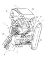
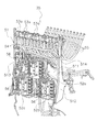
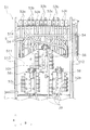
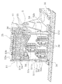
- the partial perspective view of the hydraulic shovel of FIG. The rear perspective view which shows the piping structure of FIG.
- the front perspective view which shows the piping structure of FIG.
- the top view which shows the piping structure of FIG.
- FIG. 7 is a rear perspective view showing the vicinity of the piping structure of FIG. 6;
- the side view which shows the piping structure of FIG. The perspective view which shows the state which removed piping other than the 1st piping for booms from FIG.
- the front perspective view which shows the relay part vicinity of FIG.
- the elements on larger scale of FIG. The side view which shows the state which the boom rotated upwards from FIG.
- FIG. 1 is a side view showing a configuration of a hydraulic shovel 1 according to an embodiment of the present invention.
- FIG. 2 is a partial perspective view of the hydraulic shovel 1 of the present embodiment.
- the hydraulic shovel 1 of the present embodiment has a lower traveling body 2 and an upper swing body 3.
- the lower traveling body 2 has a pair of traveling devices 20 (shown only on the left side in the figure).
- Each traveling device 20 has a track 21.
- the crawler 21 is driven by the driving force from the engine, and the hydraulic shovel 1 travels.
- the terms “upper”, “lower”, “front”, “rear”, “left”, and “right” are terms based on the operator seated in the driver's seat of the cab 31.
- the “front”, “rear”, “left” and “right” are “front” and “rear” of the lower traveling body 2 in a state where the working machine 34 described later is disposed along the traveling direction of the lower traveling body 2 Match “left” and "right”.
- the upper swing body 3 includes a swing frame 30, a cab 31, an engine compartment 32, a counterweight 33, a work machine 34, a piping structure 35 (see FIG. 2), a first passage 36, and a second passage 37. And.
- the pivot frame 30 is pivotably disposed on the upper side of the lower traveling body 2.
- the cab 31 is disposed on the front left side of the upper swing body 3 of the swing frame 30.
- the cab 31 is provided with a driver's seat.
- the engine compartment 32 is disposed at the rear of the swing frame 30, and an engine or the like is disposed inside.
- the counterweight 33 is provided at the rear of the engine room 32.
- the work implement 34 is disposed at the front center of the swing frame 30, and has a boom 41, an arm 42, a digging bucket 43, a boom cylinder 44, an arm cylinder 45 and a bucket cylinder 46 as shown in FIG.
- the proximal end of the boom 41 is pivotally connected to the pivot frame 30.
- the distal end of the boom 41 is rotatably connected to the proximal end of the arm 42.
- the tip of the arm 42 is rotatably connected to the digging bucket 43.
- a boom cylinder 44 is provided between the swing frame 30 and the boom 41.
- An arm cylinder 45 is provided between the boom 41 and the arm 42.
- a bucket cylinder 46 is provided between the arm 42 and the digging bucket 43.
- the boom cylinder 44, the arm cylinder 45, and the bucket cylinder 46 are all hydraulic cylinders. By driving these hydraulic cylinders, the boom 41, the arm 42 and the digging bucket 43 rotate, and the working machine 34 is driven. Thus, work such as digging is performed.
- the piping structure 35 is provided at the center of the swing frame 30, and from the main valves 52a, 52b, 52c (see FIG. 3 described later) And, the pressure oil is supplied to the working machine side pipe 38 connected to the bucket cylinder 46.
- the first passage 36 is provided on the front side of the engine compartment 32 and on the rear side of the piping structure 35, as shown in FIG.
- the first passage 36 is formed to penetrate from the left side surface to the right side surface of the upper swing body 3.
- the first passage 36 is used by a worker when performing maintenance on the main valves 52a, 52b, 52c.
- the second passage 37 is provided at the rear end of the engine compartment 32 along the left-right direction.
- the second passage 37 is used by a worker when performing maintenance on an engine or the like in the engine room 32.
- the second passage 37 is provided with a door.
- FIG. 3 is a perspective view of the piping structure 35 as viewed from the rear right side.
- FIG. 4 is a perspective view of the piping structure 35 as viewed from the front left side.
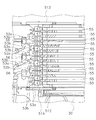
- FIG. 5 is a plan view of the piping structure 35.
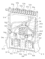
- FIG. 6 is a rear view of the piping structure 35. As shown in FIG. FIG. 6 is a view from which piping and the like not directly related to the following description are removed.
- the piping structure 35 includes a bracket 51, three main valves 52a, 52b, 52c, 12 relay parts 53a, 53b, a plurality of first pipes 54, and a plurality of first pipes 54, as shown in FIGS. It has two pipes 55 and three filters 56.
- the three main valves 52a, 52b, 52c and 12 relay parts 53a, 53b are attached to the bracket 51.
- the plurality of first pipes 54 connect between the three main valves 52a, 52b, 52c and the relay portions 53a, 53b, as shown in FIG.
- the plurality of second pipes 55 connect between the relay portions 53 a and 53 b and the work machine side pipe 38 provided on the back side of the boom 41.
- the filter 56 removes dust and the like from the pressure oil supplied to the main valves 52a, 52b, 52c.
- FIG. 7 is a perspective view of FIG. 6 and also includes the structure around the bracket 51. As shown in FIG. 7, the bracket 51 is disposed on the front side of the first passage 36. As shown in FIG. 6, the bracket 51 is gate-shaped as viewed in the front-rear direction, and includes a valve attachment portion 511, a right support portion 512, a left support portion 513, and a block attachment portion 514.
- the valve attachment portion 511 is attached with the main valves 52a, 52b, 52c.
- the valve attachment portion 511 has a plate shape, and is disposed such that the main surface (rear surface 511a, front surface 511b) is substantially parallel to the left-right direction and substantially parallel to the vertical direction.
- the right support portion 512 is disposed on the right side of the plate-like valve mounting portion 511 along the vertical direction.
- the right support portion 512 is formed such that the length in the front-rear direction becomes longer as it goes downward.
- the left support portion 513 is disposed on the left side of the plate-like valve attachment portion 511 along the vertical direction.
- the left support 513 is formed such that the length in the front-rear direction becomes longer as it goes downward.
- the right support portion 512 and the left support portion 513 are formed approximately symmetrically.
- the relay unit 53a, 53b is attached to the block attachment unit 514.
- the block attachment portion 514 is rod-shaped and disposed in the left-right direction, and both ends thereof are connected to the vicinity of the upper end portion of the right support portion 512 and the vicinity of the upper end portion of the left support portion 513.
- the right support portion 512 and the left support portion 513 are provided to support the plate-like valve attachment portion 511 and the block attachment portion 514, and as shown in FIG. It is formed in shape.
- the valve attachment portion 511 is formed up to about half the height of the right support portion 512 and the left support portion 513 in the vertical direction. Thus, a space S is formed between the valve attachment portion 511 and the block attachment portion 514.
- a first pipe 54 described later passes through the space S.
- each main valve 52a, 52b, 52c has four spools, and the spools (not shown) are arranged along the left-right direction.
- the main valves 52a, 52b, 52c are arranged such that their longitudinal direction (see arrow C) is along the height direction of the bracket 51 (vertical direction (see arrow A in FIG. 6)). That is, the spools of the main valves 52a, 52b, 52c are disposed perpendicularly to the longitudinal direction C.
- the main valve 52 a is disposed above the valve mounting portion 511.
- the main valve 52 b is disposed on the right side of the lower portion of the valve mounting portion 511.
- the main valve 52 c is disposed on the left side of the lower portion of the valve mounting portion 511.
- the main valve 52a is disposed on the upper side between the lower main valve 52b and the main valve 52c in the left-right direction.
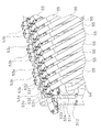
- FIG. 8 is a side view of the piping structure 35. As shown in FIG. As shown in FIG. 8, at least a part of each of the main valves 52a, 52b, 52c overlaps the bracket 51 in a side view. In FIG. 8, since the main valve 52c is located on the back side of the main valve 52b in the drawing, reference numerals are given in parentheses. Specifically, the right support portion 512 of the bracket 51 has a width in the front-rear direction, and at least a part of each of the main valves 52a, 52b, 52c overlaps the right support portion 512 in a right side view. The left support 513 of the bracket 51 has a width in the front-rear direction, and at least a part of each of the main valves 52a, 52b, 52c overlaps the left support 513 in a left side view.
- FIG. 9 is a perspective view of the bracket 51 as viewed from the front surface 511b side. Only the first pipe 54 for the boom cylinder 44 is shown in FIG. Three through holes 511 c are formed in the valve attachment portion 511. Each of the three main valves 52a, 52b, 52c is attached to the rear surface 511a so as to close the through hole 511c, and an outlet port 521 is provided in the through hole 511c. Each main valve 52a, 52b, 52c has four cylinders and has eight outlet ports 521. A branch block 522 that branches one outlet port 521 into two outlet ports 523 is provided on the front surface 511b side of the main valve 52a.
- FIG. 10 is an enlarged view of the vicinity of the relay portions 53a and 53b viewed from the front side. As shown in FIG. 6, the plurality of relay portions 53 a and 53 b are attached to the upper side of the block attachment portion 514 side by side in the left-right direction.
- 12 relay parts 53a and 53b shown in FIG. 6 are divided into three groups of four each from the left side, and each group relays pressure oil toward the boom cylinder 44, the arm cylinder 45, or the bucket cylinder 46. Do. Of the four relays 53a and 53b in one group, two relays 53b are connected to the side of the head and bottom of the cylinder that is contracted by gravity, and the other two relays 53a are opposite Connected to the side.
- the hydraulic shovel 1 of the present embodiment is large, the amount of pressure oil to be supplied is large, and two pipes are required. Therefore, two relay portions 53a, two for each of the head and the cylinder, 53b is provided.
- the relay unit 53 a includes a block unit 531 and a connection unit 532.
- the relay unit 53 b includes a block unit 531 ′ and a connection unit 532.
- the block portion 531 ' is provided with a fixed throttle and a safety valve, and the block portion 531 is not provided with them.
- Each block portion 531, 531 ′ is attached to the block attachment portion 514 by an L-shaped attachment bracket 533.
- the mounting bracket 533 is fixed to the upper surface of the block mounting portion 514 by a screw 534.
- a hole is formed in the mounting bracket 533, and a screw 534 is inserted from above. The holes are formed to be long in the left-right direction, and the left and right positions of the relay portions 53a and 53b can be adjusted.
- the first pipe 54 is connected to the block portions 531 and 531 ′ from below on the rear side of the block attachment portion 514.
- the connection portion 532 is fixed to the surface on the front side (the side of the work machine 34) of the block portions 531 and 531 ', and the second pipe 55 is connected to the tip thereof.
- the connection portion 532 is made of metal and is provided to extend obliquely downward from the block portions 531 and 531 ′.
- FIG. 11 is an enlarged plan view in the vicinity of the relay portions 53a and 53b. As shown in FIG. 11, at least a part of the relay portions 53a and 53b overlaps the main valves 52a, 52b and 52c in a plan view. That is, the relay portions 53a and 53b are disposed almost directly above the main valves 52a, 52b and 52c. Thereby, the distance in the front-rear direction between the relay portions 53a, 53b and the main valves 52a, 52b, 52c can be shortened as much as possible.
- the plurality of first pipes 54 are metal pipes and connect between the outlet ports 521 and 523 of the three main valves 52 and the 12 relay portions 53a and 53b (see FIGS. 3 and 4). In FIG. 9, a plurality of first pipes 54 to be supplied to the boom cylinder 44 among the plurality of first pipes 54 are shown.
- each of the three main valves 52a, 52b, 52c has an outlet port 521 for supplying pressure oil to the head of the boom cylinder 44, a total of three are provided.
- two relay parts 53a for relaying the pressure oil supplied to the head of the boom cylinder 44 are provided.
- One outlet port 521 of the main valve 52a is divided into two outlet ports 523 in order to supply pressure oil from the three outlet ports 521 to the two relay portions 53a.
- the pressure oil from one of the two outlet ports 523 merges with the pressure oil from the outlet port 521 of the main valve 52b and is supplied to the relay portion 53a, and the pressure oil from the other outlet port 523 is
- the pressure oil from the outlet port 521 of the main valve 52c is joined and supplied to the relay portion 53a.
- each of the three main valves 52a, 52b, 52c has an outlet port 521 for supplying pressure oil to the bottom of the boom cylinder 44, a total of three are provided.
- two relay parts 53b for relaying the pressure oil supplied to the bottom of the boom cylinder 44 are provided.
- One outlet port 521 of the main valve 52a is divided into two outlet ports 523 in order to supply pressure oil from the three outlet ports 521 to the two relay portions 53b.
- the pressure oil from one of the two outlet ports 523 merges with the pressure oil from the outlet port 521 of the main valve 52b and is supplied to the relay portion 53b, and the pressure oil from the other outlet port 523 is main
- the pressure oil from the outlet port 521 of the valve 52c is joined and supplied to the relay portion 53b.
- the first pipe 54 (shown as 54e in FIG. 9) connecting the main valve 52b and the relay portion 53b, the first pipe 54 (in FIG. 9) 54f from the main valve 52a.
- the first pipe 54 (shown as 54h in FIG. 9) from the main valve 52a joins the first pipe 54 (shown as 54g in FIG. 9) connecting the main valve 52c and the relay portion 53b. doing.
- the plurality of first pipes 54 are provided along the front surface 511b of the valve attachment portion 511 from the main valves 52a, 52b, 52c, and move rearward from the valve attachment portion 511 through the space S to It is connected to relay part 53a, 53b. As described above, in the present embodiment, the entire first pipe 54 is disposed along the bracket 51. Further, although the first pipe 54 for supplying pressure oil to the boom cylinder 44 has been described above, the first pipe 54 for supplying pressure oil to the arm cylinder 45 and the bucket cylinder 46 has substantially the same configuration.
- the plurality of second pipes 55 have flexibility, and as shown in FIGS. 4 and 5, connect the plurality of relay portions 53 a and 53 b and the work machine side pipe 38. Since the connection portion 532 of the relay portions 53a and 53b extends downward and forward, the second pipe 55 is curved so as to protrude downward.
- the working machine side pipe 38 is provided on the rear upper side of the working machine 34 along the boom 41 as shown in FIG. 8, and the second pipe 55 is connected to the rear end of the working machine side pipe 38 ing.
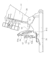
- FIG. 12 is a view showing the boom 41 pivoted upward. As described above, when the boom 41 pivots upward, the second pipe 55 has a curved shape that is formed to project downward, and is bent or bent.
- the filter 56 is provided to each of the three main valves 52a, 52b, 52c as shown in FIGS.
- the filter 56 removes dust and the like from the pressure oil supplied to the main valves 52a, 52b and 52c, and the pressure oil having passed through the filter 56 is fed to the main valves 52a, 52b and 52c.
- a main body side pipe 39 through which pressure oil supplied from the main pump flows is connected to the filters 56 of the main valves 52a, 52b, 52c.
- the filter 56 is disposed on the first passage 36 side of the main valves 52a, 52b, 52c.
- the hydraulic shovel 1 (an example of a working machine) according to the present embodiment, as shown in FIGS. 2 and 3, includes a work machine 34, main valves 52a, 52b, 52c (an example of a control valve), and a relay portion 53a, 53 b, a first pipe 54, and a second pipe 55.
- the work machine 34 has a boom cylinder 44, an arm cylinder 45 and a bucket cylinder 46 (an example of an actuator), and a work machine side pipe 38 connected to the boom cylinder 44, the arm cylinder 45 and the bucket cylinder 46.
- the main valves 52 a, 52 b, 52 c control pressure oil supplied to the boom cylinder 44, the arm cylinder 45 and the bucket cylinder 46.
- the relay portions 53a, 53b are disposed above the main valves 52a, 52b, 52c, and relay pressure oil supplied from the main valves 52a, 52b, 52c to the boom cylinder 44, the arm cylinder 45 and the bucket cylinder 46.
- the first pipe 54 connects the main valves 52a, 52b, 52c and the relay portions 53a, 53b.
- the second pipe 55 connects the relay units 53 a and 53 b to the work machine side pipe 38.
- the relay units 53 a and 53 b include block units 531 and 531 ′ (an example of a relay unit main body) and a connection unit 532.
- connection portion 532 is provided obliquely downward from the block portions 531 and 531 ′ on the work machine 34 side of the block portions 531 and 531 ′, and the second pipe 55 is connected.
- the relay portions 53a and 53b overlap at least a part of the main valves 52a, 52b and 52c in plan view.
- the relay portions 53a, 53b overlap at least a part of the main valves 52a, 52b, 52c. Therefore, the distances from the main valves 52a, 52b, 52c to the relay portions 53a, 53b can be shortened, and the pressures from the main valves 52a, 52b, 52c to the boom cylinder 44, arm cylinder 45 and bucket cylinder 46 of the working machine 34 It becomes possible to shorten the length of the piping structure 35 which supplies oil in the front-rear direction.
- outlet ports 521, 523 (the main piping 52 in the main valve 52a, 52b, 52c (an example of a control valve))
- An example of the connection port is on the work machine 34 side of the main valves 52a, 52b, 52c in plan view.
- the first pipe 54 is connected to the block portions 531 and 531 ′ from below.
- the length in the front-rear direction of the pipe structure 35 can be shortened.
- the hydraulic shovel 1 (an example of a working machine) of the present embodiment further includes a bracket 51, as shown in FIG.
- the bracket 51 supports the main valves 52a, 52b, 52c (an example of a control valve) and the relay portions 53a, 53b.
- the main valves 52a, 52b, 52c and the relay portions 53a, 53b can be disposed in one bracket 51.
- a plurality of main valves 52a, 52b, 52c (an example of a control valve) are provided. At least a part of the plurality of main valves 52a, 52b, 52c is disposed on the bracket 51 at a position shifted in the height direction. Thus, the main valves 52a, 52b and 52c can be disposed by effectively utilizing the space in the vertical direction.
- the hydraulic shovel 1 (an example of a working machine) of the present embodiment further includes a first passage 36 (an example of a passage) as shown in FIG. 7.
- the first passage 36 is formed at the rear of the main valves 52a, 52b, 52c (an example of the control valve) along the width direction (also referred to as the left-right direction) of the hydraulic shovel 1. This facilitates maintenance of the main valves 52a, 52b, 52c.
- the hydraulic shovel 1 (an example of a working machine) of the present embodiment further includes a first passage 36 (an example of a passage) as shown in FIG. 7.
- the first passage 36 is formed at the rear of the main valves 52a, 52b, 52c (an example of the control valve) along the width direction (also referred to as the left-right direction) of the hydraulic shovel 1.
- the main valves 52a, 52b, 52c are disposed on a rear surface 511a (an example of a surface) of the bracket 51 on the first passage 36 side. As a result, maintenance of the main valves 52a, 52b, 52c and the relay portions 53a, 53b disposed on the bracket 51 can be facilitated.
- the hydraulic shovel 1 (an example of a working machine) of the present embodiment further includes a filter 56, as shown in FIG.
- the pressure oil supplied to the main valves 52a, 52b, 52c passes through the filter 56.
- the filter 56 is disposed on a rear surface 511 a (an example of a surface) of the bracket 51 on the side of the first passage 36. This facilitates maintenance such as periodic replacement of the filter 56.
- the main valves 52a, 52b, 52c are attached to the bracket 51 so that the longitudinal direction thereof is along the height direction of the bracket 51.
- the present invention is not limited to this. It may be attached to the bracket 51 along the direction (left and right direction (see arrow B in FIG. 6)).
- bracket 51 is gate-shaped in a front view, but is not limited to the gate-shaped, and may be H-shaped or T-shaped.
- the work machine according to the present invention has an effect that the length in the front-rear direction of the entire work machine can be shortened by devising the piping configuration for supplying pressure oil to the work machine, and is useful as a hydraulic shovel or the like .
Landscapes
- Engineering & Computer Science (AREA)
- Mining & Mineral Resources (AREA)
- Civil Engineering (AREA)
- General Engineering & Computer Science (AREA)
- Structural Engineering (AREA)
- Component Parts Of Construction Machinery (AREA)
Abstract
油圧ショベル(1)の作業機(34)における中継部(53a、53b)は、メインバルブ(52a、52b、52c)の上方に配置され、メインバルブ(52a、52b、52c)からブームシリンダ(44)、アームシリンダ(45)およびバケットシリンダ(46)に供給される圧油を中継する。第1配管(54)は、メインバルブ(52a、52b、52c)と中継部(53a、53b)とを接続する。第2配管(55)は、中継部(53a、53b)と作業機側配管(38)とを接続する。中継部(53a、53b)は、ブロック部(531、531´)と、接続部(532)とを有する。接続部(532)は、ブロック部(531、531´)の作業機(34)側において、ブロック部(531、531´)から斜め下方向に向かって設けられ、第2配管(55)が接続される。平面視において中継部(53a、53b)は、メインバルブ(52a、52b、52c)の少なくとも一部と重なっている。
Description
本発明は、作業機械に関する。
作業機械の一例である油圧ショベルは、作業機としてブーム、アームおよびバケットを有しており、ブーム、アームおよびバケットは、複数の油圧シリンダによって駆動される。これらの油圧シリンダは、油圧ポンプからの圧油の流れを制御弁で制御して駆動制御されている(例えば、特許文献1参照。)。
特許文献1に示す油圧ショベルには、油圧シリンダに繋がっているブーム側配管に制御弁を接続する配管構成が設けられている。配管構成は、制御弁と、本体側配管と、中継箇所とを有している。本体側配管は、制御弁と作業機のアクチュエータに繋がるブーム側配管との間を接続する。本体側配管は、第1の本体側配管と第2の本体側配管の2つの配管に分けられており、第1の本体側配管は、制御弁と制御弁の前方に設けられた中継箇所との間を接続し、第2の本体側配管は中継箇所とブーム側配管の間を接続している。
特許文献1に示す油圧ショベルには、油圧シリンダに繋がっているブーム側配管に制御弁を接続する配管構成が設けられている。配管構成は、制御弁と、本体側配管と、中継箇所とを有している。本体側配管は、制御弁と作業機のアクチュエータに繋がるブーム側配管との間を接続する。本体側配管は、第1の本体側配管と第2の本体側配管の2つの配管に分けられており、第1の本体側配管は、制御弁と制御弁の前方に設けられた中継箇所との間を接続し、第2の本体側配管は中継箇所とブーム側配管の間を接続している。
しかしながら、上記特許文献1に示す構成では、中継箇所が設けられているブラケットよりも後方に制御弁が設けられているため、中継箇所から制御弁まで油圧配管で接続すると、油圧配管の長さ分、作業機械の全体の前後方向の長さが長くなっていた。
本発明は、作業機に圧油を供給する配管構成の工夫により、作業機械の全体の前後方向の長さを短くすることが可能な作業機械を提供することを目的とする。
本発明は、作業機に圧油を供給する配管構成の工夫により、作業機械の全体の前後方向の長さを短くすることが可能な作業機械を提供することを目的とする。
(課題を解決するための手段)
発明にかかる作業機械は、作業機と、制御弁と、中継部と、第1配管と、第2配管と、を備える。作業機は、アクチュエータと、アクチュエータに繋がる作業機側配管と、を有する。制御弁は、アクチュエータに供給される圧油を制御する。中継部は、制御弁の上方に配置され、制御弁からアクチュエータに供給される圧油を中継する。第1配管は、制御弁と中継部とを接続する。第2配管は、中継部と作業機側配管とを接続する。中継部は、中継部本体と、接続部とを有する。接続部は、中継部本体の作業機側において、中継部本体から斜め下方向に向かって設けられ、第2配管が接続される。平面視において中継部は、制御弁の少なくとも一部と重なっている。
発明にかかる作業機械は、作業機と、制御弁と、中継部と、第1配管と、第2配管と、を備える。作業機は、アクチュエータと、アクチュエータに繋がる作業機側配管と、を有する。制御弁は、アクチュエータに供給される圧油を制御する。中継部は、制御弁の上方に配置され、制御弁からアクチュエータに供給される圧油を中継する。第1配管は、制御弁と中継部とを接続する。第2配管は、中継部と作業機側配管とを接続する。中継部は、中継部本体と、接続部とを有する。接続部は、中継部本体の作業機側において、中継部本体から斜め下方向に向かって設けられ、第2配管が接続される。平面視において中継部は、制御弁の少なくとも一部と重なっている。
(発明の効果)
本発明によれば、作業機に圧油を供給する配管構成の工夫により、作業機械の全体の前後方向の長さを短くすることが可能な作業機械を提供することができる。
本発明によれば、作業機に圧油を供給する配管構成の工夫により、作業機械の全体の前後方向の長さを短くすることが可能な作業機械を提供することができる。
本発明の作業機械の一例である油圧ショベルについて図面を参照しながら以下に説明する。
<1.構成>
(1-1.油圧ショベルの概要)
図1は、本発明にかかる実施の形態の油圧ショベル1の構成を示す側面図である。図2は、本実施の形態の油圧ショベル1の部分斜視図である。
<1.構成>
(1-1.油圧ショベルの概要)
図1は、本発明にかかる実施の形態の油圧ショベル1の構成を示す側面図である。図2は、本実施の形態の油圧ショベル1の部分斜視図である。
本実施の形態の油圧ショベル1は、下部走行体2と、上部旋回体3と、を有する。下部走行体2は、一対の走行装置20(図では左側のみ示す)を有する。各々の走行装置20は、履帯21を有している。エンジンからの駆動力によって履帯21が駆動され、油圧ショベル1は、走行する。
なお、本明細書の説明において、「上」「下」「前」「後」「左」「右」とは、キャブ31の運転席に着座したオペレータを基準とする用語である。すなわち、この「前」「後」「左」「右」は、後述する作業機34が下部走行体2の進行方向に沿って配置されている状態では下部走行体2の「前」「後」「左」「右」と一致する。
なお、本明細書の説明において、「上」「下」「前」「後」「左」「右」とは、キャブ31の運転席に着座したオペレータを基準とする用語である。すなわち、この「前」「後」「左」「右」は、後述する作業機34が下部走行体2の進行方向に沿って配置されている状態では下部走行体2の「前」「後」「左」「右」と一致する。
上部旋回体3は、旋回フレーム30と、キャブ31と、エンジンルーム32と、カウンタウェイト33と、作業機34と、配管構造35(図2参照)と、第1通路36と、第2通路37と、を有する。
旋回フレーム30は、下部走行体2の上側に旋回可能に配置されている。キャブ31は、旋回フレーム30の上部旋回体3の前部左側に配置されている。キャブ31には、運転席が配置されている。エンジンルーム32は、旋回フレーム30の後部に配置されており、内側にエンジンなどが配置されている。カウンタウェイト33は、エンジンルーム32の後方に設けられている。
旋回フレーム30は、下部走行体2の上側に旋回可能に配置されている。キャブ31は、旋回フレーム30の上部旋回体3の前部左側に配置されている。キャブ31には、運転席が配置されている。エンジンルーム32は、旋回フレーム30の後部に配置されており、内側にエンジンなどが配置されている。カウンタウェイト33は、エンジンルーム32の後方に設けられている。
作業機34は、旋回フレーム30の前部中央に配置されており、図1に示すようにブーム41、アーム42、掘削バケット43、ブームシリンダ44、アームシリンダ45およびバケットシリンダ46と、を有する。ブーム41の基端部は、旋回フレーム30に回動可能に連結されている。また、ブーム41の先端部はアーム42の基端部に回動可能に連結されている。アーム42の先端部は、掘削バケット43に回動可能に連結されている。
また、旋回フレーム30とブーム41の間にブームシリンダ44が設けられている。ブーム41とアーム42の間にアームシリンダ45が設けられている。アーム42と掘削バケット43の間にバケットシリンダ46が設けられている。ブームシリンダ44、アームシリンダ45、およびバケットシリンダ46は、いずれも油圧シリンダである。これら油圧シリンダが駆動されることによってブーム41、アーム42および掘削バケット43が回動し、作業機34が駆動される。これにより、掘削等の作業が行われる。
配管構造35は、詳しくは後述するが、図2に示すように旋回フレーム30の中央に設けられており、メインバルブ52a、52b、52c(後述する図3参照)からブームシリンダ44、アームシリンダ45およびバケットシリンダ46に繋がる作業機側配管38まで圧油を供給する。
第1通路36は、図2に示すように、エンジンルーム32の前側であって配管構造35の後側に設けられている。第1通路36は、上部旋回体3の左側面から右側面まで貫通して形成されている。第1通路36は、メインバルブ52a、52b、52cのメンテナンスを行う際に作業者に利用される。
第2通路37は、図2に示すように、エンジンルーム32の後端部に左右方向に沿って設けられている。第2通路37は、エンジンルーム32内のエンジンなどのメンテナンスを行う際に作業者に利用される。なお、第2通路37には、扉が設けられている。
第1通路36は、図2に示すように、エンジンルーム32の前側であって配管構造35の後側に設けられている。第1通路36は、上部旋回体3の左側面から右側面まで貫通して形成されている。第1通路36は、メインバルブ52a、52b、52cのメンテナンスを行う際に作業者に利用される。
第2通路37は、図2に示すように、エンジンルーム32の後端部に左右方向に沿って設けられている。第2通路37は、エンジンルーム32内のエンジンなどのメンテナンスを行う際に作業者に利用される。なお、第2通路37には、扉が設けられている。
(1-2.配管構造35)
配管構造35は、上述したように旋回フレーム30の中央に設けられている。図3は、配管構造35を後方右側から視た斜視図である。図4は、配管構造35を前方左側から視た斜視図である。図5は、配管構造35の平面図である。図6は、配管構造35の背面図である。図6は、以下の説明と直接関係しない配管などを取り除いた図である。
配管構造35は、上述したように旋回フレーム30の中央に設けられている。図3は、配管構造35を後方右側から視た斜視図である。図4は、配管構造35を前方左側から視た斜視図である。図5は、配管構造35の平面図である。図6は、配管構造35の背面図である。図6は、以下の説明と直接関係しない配管などを取り除いた図である。
配管構造35は、図3および図4に示すようにブラケット51と、3つのメインバルブ52a、52b、52cと、12個の中継部53a、53bと、複数の第1配管54と、複数の第2配管55と、3つのフィルター56と、を有する。
ブラケット51には、3つのメインバルブ52a、52b、52cと12個の中継部53a、53bが取り付けられている。複数の第1配管54は、図3に示すように3つのメインバルブ52a、52b、52cと中継部53a、53bの間を接続する。複数の第2配管55は、図5に示すように中継部53a、53bと、ブーム41の背面側に設けられた作業機側配管38との間を接続する。フィルター56は、メインバルブ52a、52b、52cに供給される圧油より粉塵などを除去する。
ブラケット51には、3つのメインバルブ52a、52b、52cと12個の中継部53a、53bが取り付けられている。複数の第1配管54は、図3に示すように3つのメインバルブ52a、52b、52cと中継部53a、53bの間を接続する。複数の第2配管55は、図5に示すように中継部53a、53bと、ブーム41の背面側に設けられた作業機側配管38との間を接続する。フィルター56は、メインバルブ52a、52b、52cに供給される圧油より粉塵などを除去する。
(1-2-1.ブラケット51)
図7は、図6の斜視図であり、ブラケット51の周囲の構造も含む。図7に示すように、ブラケット51は、第1通路36の前側に配置されている。ブラケット51は、図6に示すように前後方向に沿って視て門型であり、バルブ取付部511と、右支持部512と、左支持部513と、ブロック取付部514と、を有する。
図7は、図6の斜視図であり、ブラケット51の周囲の構造も含む。図7に示すように、ブラケット51は、第1通路36の前側に配置されている。ブラケット51は、図6に示すように前後方向に沿って視て門型であり、バルブ取付部511と、右支持部512と、左支持部513と、ブロック取付部514と、を有する。
バルブ取付部511は、メインバルブ52a、52b、52cが取り付けられる。バルブ取付部511は、板状であり、主面(後面511a、前面511b)が左右方向と略平行且つ上下方向と略平行になるように配置されている。
右支持部512は、板状のバルブ取付部511の右側に上下方向に沿って配置されている。右支持部512は、下方に向かうに従って前後方向の長さが長くなるように形成されている。左支持部513は、板状のバルブ取付部511の左側に上下方向に沿って配置されている。左支持部513は、下方に向かうに従って前後方向の長さが長くなるように形成されている。右支持部512と左支持部513は概ね対称に形成されている。
右支持部512は、板状のバルブ取付部511の右側に上下方向に沿って配置されている。右支持部512は、下方に向かうに従って前後方向の長さが長くなるように形成されている。左支持部513は、板状のバルブ取付部511の左側に上下方向に沿って配置されている。左支持部513は、下方に向かうに従って前後方向の長さが長くなるように形成されている。右支持部512と左支持部513は概ね対称に形成されている。
ブロック取付部514は、中継部53a、53bが取り付けられる。ブロック取付部514は、棒状であり、左右方向に沿って配置されており、その両端が右支持部512の上端部近傍と、左支持部513の上端部近傍に接続されている。
なお、右支持部512と左支持部513は、板状のバルブ取付部511およびブロック取付部514を支えるように設けられており、図5に示すように、ブラケット51は、平面視において概ねH形状に形成されている。
バルブ取付部511は、上下方向において右支持部512および左支持部513の概ね半分程度の高さまで形成されている。これにより、バルブ取付部511とブロック取付部514の間に空間Sが形成されている。この空間Sは、後述する第1配管54が通過する。
なお、右支持部512と左支持部513は、板状のバルブ取付部511およびブロック取付部514を支えるように設けられており、図5に示すように、ブラケット51は、平面視において概ねH形状に形成されている。
バルブ取付部511は、上下方向において右支持部512および左支持部513の概ね半分程度の高さまで形成されている。これにより、バルブ取付部511とブロック取付部514の間に空間Sが形成されている。この空間Sは、後述する第1配管54が通過する。
(1-2-2.メインバルブ52a、52b、52c)
3つのメインバルブ52a、52b、52cは、図3および図7に示すようにバルブ取付部511の後面511aに取り付けられている。本実施の形態では、各々のメインバルブ52a、52b、52cは、4つのスプールを有しており、スプール(図示せず)が左右方向に沿うように配置されている。
3つのメインバルブ52a、52b、52cは、図3および図7に示すようにバルブ取付部511の後面511aに取り付けられている。本実施の形態では、各々のメインバルブ52a、52b、52cは、4つのスプールを有しており、スプール(図示せず)が左右方向に沿うように配置されている。
メインバルブ52a、52b、52cは、その長手方向(矢印C参照)がブラケット51の高さ方向(上下方向(図6の矢印A参照))に沿って配置されている。すなわち、メインバルブ52a、52b、52cは、その長手方向Cに対して垂直にスプールが配置されている。
メインバルブ52aは、バルブ取付部511の上部に配置されている。メインバルブ52bは、バルブ取付部511の下部の右側に配置されている。メインバルブ52cは、バルブ取付部511の下部の左側に配置されている。メインバルブ52aは、左右方向において下側のメインバルブ52bとメインバルブ52cの間の上側に配置されている。
メインバルブ52aは、バルブ取付部511の上部に配置されている。メインバルブ52bは、バルブ取付部511の下部の右側に配置されている。メインバルブ52cは、バルブ取付部511の下部の左側に配置されている。メインバルブ52aは、左右方向において下側のメインバルブ52bとメインバルブ52cの間の上側に配置されている。
図8は、配管構造35の側面図である。図8に示すように、各々のメインバルブ52a、52b、52cの少なくとも一部は、側面視においてブラケット51と重なっている。図8では、メインバルブ52cは、メインバルブ52bの紙面奥側に位置するため括弧内に符号を示す。詳しくは、ブラケット51の右支持部512は前後方向に幅を有しており、右側面視において、各メインバルブ52a、52b、52cの少なくとも一部が右支持部512に重なっている。また、ブラケット51の左支持部513は前後方向に幅を有しており、左側面視において、各メインバルブ52a、52b、52cの少なくとも一部が左支持部513に重なっている。
図9は、ブラケット51を前面511b側から視た斜視図である。図9では、ブームシリンダ44用の第1配管54のみが図示されている。バルブ取付部511には、3つの貫通孔511cが形成されている。3つのメインバルブ52a、52b、52cの各々は、貫通孔511cを塞ぐように後面511aに取り付けられており、出口ポート521が貫通孔511cに設けられている。
各々のメインバルブ52a、52b、52cは、4つのシリンダを有しており、8つの出口ポート521を有している。なお、メインバルブ52aの前面511b側には、1つの出口ポート521を更に2つの出口ポート523に分岐する分岐ブロック522が設けられている。
各々のメインバルブ52a、52b、52cは、4つのシリンダを有しており、8つの出口ポート521を有している。なお、メインバルブ52aの前面511b側には、1つの出口ポート521を更に2つの出口ポート523に分岐する分岐ブロック522が設けられている。
(1-2-3.中継部53a、53b)
図10は、前側から見た中継部53a、53b近傍の拡大図である。複数の中継部53a、53bは、図6に示すように、ブロック取付部514の上側に左右方向に並んで取り付けられている。
図10は、前側から見た中継部53a、53b近傍の拡大図である。複数の中継部53a、53bは、図6に示すように、ブロック取付部514の上側に左右方向に並んで取り付けられている。
図6に示す12個の中継部53a、53bは例えば左側から4個ずつ3つのグループに分けられており、各々のグループは、ブームシリンダ44、アームシリンダ45またはバケットシリンダ46に向かう圧油を中継する。
1つのグループ内の4個の中継部53a、53bのうち2つの中継部53bは、シリンダのヘッドおよびボトムのうち自重落下によって収縮する側に接続され、他の2つの中継部53aは、その反対側に接続される。なお、本実施の形態の油圧ショベル1は大型であるため、供給する圧油の量が多く、配管が2本必要となるため、ヘッドおよびシリンダの各々に対して2つずつの中継部53a、53bが設けられている。
1つのグループ内の4個の中継部53a、53bのうち2つの中継部53bは、シリンダのヘッドおよびボトムのうち自重落下によって収縮する側に接続され、他の2つの中継部53aは、その反対側に接続される。なお、本実施の形態の油圧ショベル1は大型であるため、供給する圧油の量が多く、配管が2本必要となるため、ヘッドおよびシリンダの各々に対して2つずつの中継部53a、53bが設けられている。
中継部53aは、ブロック部531と接続部532とを有する。中継部53bは、ブロック部531´と、接続部532とを有している。ブロック部531´には、固定絞りと安全弁が設けられており、ブロック部531には、それらが設けられていない。
各々のブロック部531、531´は、ブロック取付部514にL字状の取付ブラケット533によって取り付けられている。取付ブラケット533は、ブロック取付部514の上面にネジ534によって固定されている。取付ブラケット533に孔が形成されており、上方からネジ534が挿入される。なお、孔は左右方向に長い形状に形成されており、中継部53a、53bの左右位置を調整することができる。
各々のブロック部531、531´は、ブロック取付部514にL字状の取付ブラケット533によって取り付けられている。取付ブラケット533は、ブロック取付部514の上面にネジ534によって固定されている。取付ブラケット533に孔が形成されており、上方からネジ534が挿入される。なお、孔は左右方向に長い形状に形成されており、中継部53a、53bの左右位置を調整することができる。
ブロック部531、531´には、図7に示すようにブロック取付部514の後側において第1配管54が下方から接続される。接続部532は、ブロック部531、531´の前側(作業機34側)の面に固定されており、その先端には第2配管55が接続される。接続部532は、金属製であり、ブロック部531、531´から斜め下方に向かって延びるように設けられている。
図11は、中継部53a、53b近傍の拡大平面図である。図11に示すように、平面視において中継部53a、53bの少なくとも一部は、メインバルブ52a、52b、52cと重なっている。すなわち、メインバルブ52a、52b、52cの概ね真上に中継部53a、53bが配置されている。これにより、中継部53a、53bとメインバルブ52a、52b、52cの間の前後方向の距離を出来るだけ短くすることができる。
(1-2-4.第1配管54)
複数の第1配管54は、金属製の配管であり、3つのメインバルブ52の出口ポート521、523と12個の中継部53a、53bの間を接続する(図3および図4参照)。図9では、複数の第1配管54のうちブームシリンダ44へと供給される複数の第1配管54が示されている。
複数の第1配管54は、金属製の配管であり、3つのメインバルブ52の出口ポート521、523と12個の中継部53a、53bの間を接続する(図3および図4参照)。図9では、複数の第1配管54のうちブームシリンダ44へと供給される複数の第1配管54が示されている。
ブームシリンダ44のヘッドに圧油を供給する出口ポート521は、3つのメインバルブ52a、52b、52cの各々が有しているため、合計3つ設けられている。一方、ブームシリンダ44のヘッドに供給される圧油を中継する中継部53aは2つ設けられている。3つの出口ポート521から2つの中継部53aに圧油を供給するために、メインバルブ52aの1つの出口ポート521が2つの出口ポート523に分けられている。2つの出口ポート523のうち一方の出口ポート523からの圧油は、メインバルブ52bの出口ポート521からの圧油と合流して中継部53aに供給され、他方の出口ポート523からの圧油はメインバルブ52cの出口ポート521からの圧油と合流して中継部53aに供給される。
具体的には、図9に示すように、メインバルブ52bと中継部53aを接続する第1配管54(図9では54aと示す)に、メインバルブ52aからの第1配管54(図9において54bと示す)が合流し、メインバルブ52cと中継部53aを接続する第1配管54(図9では54cと示す)に、メインバルブ52aからの第1配管54(図9において54dと示す)が合流している。
同様に、ブームシリンダ44のボトムに圧油を供給する出口ポート521は、3つのメインバルブ52a、52b、52cの各々が有しているため、合計3つ設けられている。一方、ブームシリンダ44のボトムに供給される圧油を中継する中継部53bは2つ設けられている。3つの出口ポート521から2つの中継部53bに圧油を供給するために、メインバルブ52aの1つの出口ポート521が2つの出口ポート523に分けられている。2つの出口ポート523のうち一方の出口ポート523からの圧油はメインバルブ52bの出口ポート521からの圧油と合流して中継部53bに供給され、他方の出口ポート523からの圧油はメインバルブ52cの出口ポート521からの圧油と合流して中継部53bに供給される。
具体的には、図9に示すように、メインバルブ52bと中継部53bを接続する第1配管54(図9では54eと示す)に、メインバルブ52aからの第1配管54(図9において54fと示す)が合流し、メインバルブ52cと中継部53bを接続する第1配管54(図9では54gと示す)に、メインバルブ52aからの第1配管54(図9において54hと示す)が合流している。
なお、複数の第1配管54は、メインバルブ52a、52b、52cからバルブ取付部511の前面511bに沿って設けられ、空間Sを通ってバルブ取付部511よりも後側に移動して下方から中継部53a、53bに接続されている。このように、本実施の形態では第1配管54の全体がブラケット51に沿って配置されている。
また、上記ではブームシリンダ44に圧油を供給する第1配管54について説明したが、アームシリンダ45およびバケットシリンダ46に圧油を供給する第1配管54も概ね同様の構成である。
また、上記ではブームシリンダ44に圧油を供給する第1配管54について説明したが、アームシリンダ45およびバケットシリンダ46に圧油を供給する第1配管54も概ね同様の構成である。
(1-2-5.第2配管55)
複数の第2配管55は、可撓性を有し、図4および図5に示すように複数の中継部53a、53bと作業機側配管38とを接続する。中継部53a、53bの接続部532が前下方に向かって延びているため、第2配管55は、下方に向かって突出するように湾曲している。また、作業機側配管38は、図8に示すようにブーム41に沿って作業機34の後部上側に設けられており、作業機側配管38の後端であると第2配管55が接続されている。
図12は、ブーム41が、上方に回動した状態を示す図である。このようにブーム41が上方に回動した場合には、第2配管55は、下方に向かって突出するように形成された湾曲がきつくなり撓む。
複数の第2配管55は、可撓性を有し、図4および図5に示すように複数の中継部53a、53bと作業機側配管38とを接続する。中継部53a、53bの接続部532が前下方に向かって延びているため、第2配管55は、下方に向かって突出するように湾曲している。また、作業機側配管38は、図8に示すようにブーム41に沿って作業機34の後部上側に設けられており、作業機側配管38の後端であると第2配管55が接続されている。
図12は、ブーム41が、上方に回動した状態を示す図である。このようにブーム41が上方に回動した場合には、第2配管55は、下方に向かって突出するように形成された湾曲がきつくなり撓む。
(1-2-6.フィルター56)
フィルター56は、図6および図7に示すように3つのメインバルブ52a、52b、52cの各々に設けられている。フィルター56は、メインバルブ52a、52b、52cに供給される圧油から粉塵等を除去し、フィルター56を通った圧油がメインバルブ52a、52b、52cに送り込まれる。メインバルブ52a、52b、52cのフィルター56には、図6および図7に示すように、メインポンプから供給される圧油が流通する本体側配管39が接続されている。
また、フィルター56は、図7に示すようにメインバルブ52a、52b、52cの第1通路36側に配置されている。フィルター56は定期交換が必要であるが、第1通路36側に配置されているため、容易にフィルターの定期交換を行うことができる。
フィルター56は、図6および図7に示すように3つのメインバルブ52a、52b、52cの各々に設けられている。フィルター56は、メインバルブ52a、52b、52cに供給される圧油から粉塵等を除去し、フィルター56を通った圧油がメインバルブ52a、52b、52cに送り込まれる。メインバルブ52a、52b、52cのフィルター56には、図6および図7に示すように、メインポンプから供給される圧油が流通する本体側配管39が接続されている。
また、フィルター56は、図7に示すようにメインバルブ52a、52b、52cの第1通路36側に配置されている。フィルター56は定期交換が必要であるが、第1通路36側に配置されているため、容易にフィルターの定期交換を行うことができる。
<2.動作>
以上のような構成により、本体側配管39からフィルター56を通してメインバルブ52a、52b、52cに供給された圧油は、第1配管54から中継部53a、53bを介して第2配管55へと供給される。第2配管55に供給された圧油は、作業機側配管38へと供給され、ブームシリンダ44、アームシリンダ45およびバケットシリンダ46へと供給され、作業機34が駆動する。
以上のような構成により、本体側配管39からフィルター56を通してメインバルブ52a、52b、52cに供給された圧油は、第1配管54から中継部53a、53bを介して第2配管55へと供給される。第2配管55に供給された圧油は、作業機側配管38へと供給され、ブームシリンダ44、アームシリンダ45およびバケットシリンダ46へと供給され、作業機34が駆動する。
<3.特徴等>
(3-1)
本実施の形態の油圧ショベル1(作業機械の一例)は、図2および図3に示すように、作業機34と、メインバルブ52a、52b、52c(制御弁の一例)と、中継部53a、53bと、第1配管54と、第2配管55と、を備える。作業機34は、ブームシリンダ44、アームシリンダ45およびバケットシリンダ46(アクチュエータの一例)と、ブームシリンダ44、アームシリンダ45およびバケットシリンダ46に繋がる作業機側配管38と、を有する。メインバルブ52a、52b、52cは、ブームシリンダ44、アームシリンダ45およびバケットシリンダ46に供給される圧油を制御する。中継部53a、53bは、メインバルブ52a、52b、52cの上方に配置され、メインバルブ52a、52b、52cからブームシリンダ44、アームシリンダ45およびバケットシリンダ46に供給される圧油を中継する。第1配管54は、メインバルブ52a、52b、52cと中継部53a、53bとを接続する。第2配管55は、中継部53a、53bと作業機側配管38とを接続する。中継部53a、53bは、ブロック部531、531´(中継部本体の一例)と、接続部532とを有する。接続部532は、ブロック部531、531´の作業機34側において、ブロック部531、531´から斜め下方向に向かって設けられ、第2配管55が接続される。平面視において中継部53a、53bは、メインバルブ52a、52b、52cの少なくとも一部と重なっている。
(3-1)
本実施の形態の油圧ショベル1(作業機械の一例)は、図2および図3に示すように、作業機34と、メインバルブ52a、52b、52c(制御弁の一例)と、中継部53a、53bと、第1配管54と、第2配管55と、を備える。作業機34は、ブームシリンダ44、アームシリンダ45およびバケットシリンダ46(アクチュエータの一例)と、ブームシリンダ44、アームシリンダ45およびバケットシリンダ46に繋がる作業機側配管38と、を有する。メインバルブ52a、52b、52cは、ブームシリンダ44、アームシリンダ45およびバケットシリンダ46に供給される圧油を制御する。中継部53a、53bは、メインバルブ52a、52b、52cの上方に配置され、メインバルブ52a、52b、52cからブームシリンダ44、アームシリンダ45およびバケットシリンダ46に供給される圧油を中継する。第1配管54は、メインバルブ52a、52b、52cと中継部53a、53bとを接続する。第2配管55は、中継部53a、53bと作業機側配管38とを接続する。中継部53a、53bは、ブロック部531、531´(中継部本体の一例)と、接続部532とを有する。接続部532は、ブロック部531、531´の作業機34側において、ブロック部531、531´から斜め下方向に向かって設けられ、第2配管55が接続される。平面視において中継部53a、53bは、メインバルブ52a、52b、52cの少なくとも一部と重なっている。
このように、中継部53a、53bは、メインバルブ52a、52b、52cの少なくとも一部と重なっている。そのため、メインバルブ52a、52b、52cから中継部53a、53bまでの距離を短くすることができ、メインバルブ52a、52b、52cから作業機34のブームシリンダ44、アームシリンダ45およびバケットシリンダ46に圧油を供給する配管構造35の前後方向の長さを短くすることが可能となる。
また、各メインバルブ52a、52b、52cと中継部53a、53bとの前後方向の距離を短くできるため、中継部53a、53bから作業機側配管38までの前後方向の長さを長く確保することができる。このため、ブーム41の揺動時の第2配管55の曲げRを緩やかにすることができ、第2配管55の劣化を低減することができる。
また、各メインバルブ52a、52b、52cと中継部53a、53bとの前後方向の距離を短くできるため、中継部53a、53bから作業機側配管38までの前後方向の長さを長く確保することができる。このため、ブーム41の揺動時の第2配管55の曲げRを緩やかにすることができ、第2配管55の劣化を低減することができる。
(3-2)
本実施の形態の油圧ショベル1(作業機械の一例)では、図9に示すように、メインバルブ52a、52b、52c(制御弁の一例)における第1配管54と接続する出口ポート521、523(接続口の一例)は、平面視においてメインバルブ52a、52b、52cの作業機34側にある。
これにより、配管構造35の前後方向の長さをより短くすることができる。
本実施の形態の油圧ショベル1(作業機械の一例)では、図9に示すように、メインバルブ52a、52b、52c(制御弁の一例)における第1配管54と接続する出口ポート521、523(接続口の一例)は、平面視においてメインバルブ52a、52b、52cの作業機34側にある。
これにより、配管構造35の前後方向の長さをより短くすることができる。
(3-3)
本実施の形態の油圧ショベル1(作業機械の一例)では、図7に示すように、第1配管54は、ブロック部531、531´に下方から接続される。
これによって、第1配管54が接続される構造をブロック部531、531´の前または後に設ける必要がないため、配管構造35の前後方向の長さを短くすることができる。
本実施の形態の油圧ショベル1(作業機械の一例)では、図7に示すように、第1配管54は、ブロック部531、531´に下方から接続される。
これによって、第1配管54が接続される構造をブロック部531、531´の前または後に設ける必要がないため、配管構造35の前後方向の長さを短くすることができる。
(3-4)
本実施の形態の油圧ショベル1(作業機械の一例)では、図8および図12に示すように、第2配管55のうち、最も低い部分は中継部53a、53bより下方に位置している。
このように自重と同方向に湾曲させているため、無理な力が加わらず自然と湾曲するので、第2配管の寿命をより長く出来る。
本実施の形態の油圧ショベル1(作業機械の一例)では、図8および図12に示すように、第2配管55のうち、最も低い部分は中継部53a、53bより下方に位置している。
このように自重と同方向に湾曲させているため、無理な力が加わらず自然と湾曲するので、第2配管の寿命をより長く出来る。
(3-5)
本実施の形態の油圧ショベル1(作業機械の一例)は、図3に示すように、ブラケット51を更に備える。ブラケット51は、メインバルブ52a、52b、52c(制御弁の一例)と中継部53a、53bとを支持する。
これにより、メインバルブ52a、52b、52cと中継部53a、53bを1つのブラケット51に配置することができる。
本実施の形態の油圧ショベル1(作業機械の一例)は、図3に示すように、ブラケット51を更に備える。ブラケット51は、メインバルブ52a、52b、52c(制御弁の一例)と中継部53a、53bとを支持する。
これにより、メインバルブ52a、52b、52cと中継部53a、53bを1つのブラケット51に配置することができる。
(3-6)
本実施の形態の油圧ショベル1(作業機械の一例)では、図3に示すように、メインバルブ52a、52b、52c(制御弁の一例)は複数設けられている。複数のメインバルブ52a、52b、52cの少なくとも一部は、ブラケット51に高さ方向の位置をずらして配置されている。
これにより、上下方向の空間を有効に利用してメインバルブ52a、52b、52cを配置することができる。
本実施の形態の油圧ショベル1(作業機械の一例)では、図3に示すように、メインバルブ52a、52b、52c(制御弁の一例)は複数設けられている。複数のメインバルブ52a、52b、52cの少なくとも一部は、ブラケット51に高さ方向の位置をずらして配置されている。
これにより、上下方向の空間を有効に利用してメインバルブ52a、52b、52cを配置することができる。
(3-7)
本実施の形態の油圧ショベル1(作業機械の一例)は、図7に示すように、第1通路36(通路の一例)を更に備える。第1通路36は、メインバルブ52a、52b、52c(制御弁の一例)の後方に、油圧ショベル1の幅方向(左右方向ともいえる)に沿って形成されている。
これにより、メインバルブ52a、52b、52cのメンテナンスが行い易くなる。
本実施の形態の油圧ショベル1(作業機械の一例)は、図7に示すように、第1通路36(通路の一例)を更に備える。第1通路36は、メインバルブ52a、52b、52c(制御弁の一例)の後方に、油圧ショベル1の幅方向(左右方向ともいえる)に沿って形成されている。
これにより、メインバルブ52a、52b、52cのメンテナンスが行い易くなる。
(3-8)
本実施の形態の油圧ショベル1(作業機械の一例)は、図7に示すように、第1通路36(通路の一例)を更に備える。第1通路36は、メインバルブ52a、52b、52c(制御弁の一例)の後方に、油圧ショベル1の幅方向(左右方向ともいえる)に沿って形成されている。メインバルブ52a、52b、52cは、ブラケット51の第1通路36側の後面511a(面の一例)に配置されている。
これにより、ブラケット51に配置されたメインバルブ52a、52b、52cおよび中継部53a、53bのメンテナンスが行い易くなる。
本実施の形態の油圧ショベル1(作業機械の一例)は、図7に示すように、第1通路36(通路の一例)を更に備える。第1通路36は、メインバルブ52a、52b、52c(制御弁の一例)の後方に、油圧ショベル1の幅方向(左右方向ともいえる)に沿って形成されている。メインバルブ52a、52b、52cは、ブラケット51の第1通路36側の後面511a(面の一例)に配置されている。
これにより、ブラケット51に配置されたメインバルブ52a、52b、52cおよび中継部53a、53bのメンテナンスが行い易くなる。
(3-9)
本実施の形態の油圧ショベル1(作業機械の一例)は、図7に示すように、フィルター56を更に備える。フィルター56は、メインバルブ52a、52b、52cに供給される圧油が通過する。フィルター56は、ブラケット51の第1通路36の側の後面511a(面の一例)に配置されている。
これにより、フィルター56の定期交換などのメンテナンスが行い易くなる。
本実施の形態の油圧ショベル1(作業機械の一例)は、図7に示すように、フィルター56を更に備える。フィルター56は、メインバルブ52a、52b、52cに供給される圧油が通過する。フィルター56は、ブラケット51の第1通路36の側の後面511a(面の一例)に配置されている。
これにより、フィルター56の定期交換などのメンテナンスが行い易くなる。
<4.他の実施の形態>
以上、本発明の一実施形態について説明したが、本発明は上記実施形態に限定されるものではなく、発明の要旨を逸脱しない範囲で種々の変更が可能である。
(A)
上記実施の形態では、メインバルブ52a、52b、52cは、その長手方向がブラケット51の高さ方向に沿うようにブラケット51に取り付けられているが、これに限らなくても良く、ブラケット51の幅方向(左右方向(図6の矢印B参照))に沿うようにブラケット51に取り付けられていてもよい。
以上、本発明の一実施形態について説明したが、本発明は上記実施形態に限定されるものではなく、発明の要旨を逸脱しない範囲で種々の変更が可能である。
(A)
上記実施の形態では、メインバルブ52a、52b、52cは、その長手方向がブラケット51の高さ方向に沿うようにブラケット51に取り付けられているが、これに限らなくても良く、ブラケット51の幅方向(左右方向(図6の矢印B参照))に沿うようにブラケット51に取り付けられていてもよい。
(B)
上記実施の形態では、3つのメインバルブ52a、52b、52cが設けられているが、これに限られるものではなく、2つ以下であってもよいし、4つ以上であってもよい。
(C)
上記実施の形態では、ブラケット51は正面視において門型であるが、門型に限られるものではなく、H型であってもよいし、T型であってもよい。
上記実施の形態では、3つのメインバルブ52a、52b、52cが設けられているが、これに限られるものではなく、2つ以下であってもよいし、4つ以上であってもよい。
(C)
上記実施の形態では、ブラケット51は正面視において門型であるが、門型に限られるものではなく、H型であってもよいし、T型であってもよい。
(D)
上記実施の形態では、例えばブームシリンダ44のヘッドに圧油を供給するために2本の第2配管55および2つの中継部53aが用いられているが、小型若しくは中型の油圧ショベルであって圧油の量が少なくてよい場合には、ブームシリンダ44のヘッド用に1本の第2配管55および1つの中継部53aが設けられていてもよい。ブームシリンダ44のボトム側も同様に、中継部53bおよび第2配管55が1つずつのみ設けられていてもよい。また、アームシリンダ45およびバケットシリンダ46についても同様である。
上記実施の形態では、例えばブームシリンダ44のヘッドに圧油を供給するために2本の第2配管55および2つの中継部53aが用いられているが、小型若しくは中型の油圧ショベルであって圧油の量が少なくてよい場合には、ブームシリンダ44のヘッド用に1本の第2配管55および1つの中継部53aが設けられていてもよい。ブームシリンダ44のボトム側も同様に、中継部53bおよび第2配管55が1つずつのみ設けられていてもよい。また、アームシリンダ45およびバケットシリンダ46についても同様である。
本発明の作業機械は、作業機に圧油を供給する配管構成の工夫により、作業機械の全体の前後方向の長さを短くすることが可能な効果を有し、油圧ショベル等として有用である。
1 :油圧ショベル(作業機械の一例)
2 :下部走行体
3 :上部旋回体
34 :作業機
35 :配管構造
36 :第1通路(通路の一例)
38 :作業機側配管
41 :ブーム
42 :アーム
43 :掘削バケット
44 :ブームシリンダ(アクチュエータの一例)
45 :アームシリンダ(アクチュエータの一例)
46 :バケットシリンダ(アクチュエータの一例)
51 :ブラケット(取付部材の一例)
52a :メインバルブ(制御弁の一例)
52b :メインバルブ(制御弁の一例)
52c :メインバルブ(制御弁の一例)
53a :中継部
53b :中継部
54 :第1配管
55 :第2配管
56 :フィルター
2 :下部走行体
3 :上部旋回体
34 :作業機
35 :配管構造
36 :第1通路(通路の一例)
38 :作業機側配管
41 :ブーム
42 :アーム
43 :掘削バケット
44 :ブームシリンダ(アクチュエータの一例)
45 :アームシリンダ(アクチュエータの一例)
46 :バケットシリンダ(アクチュエータの一例)
51 :ブラケット(取付部材の一例)
52a :メインバルブ(制御弁の一例)
52b :メインバルブ(制御弁の一例)
52c :メインバルブ(制御弁の一例)
53a :中継部
53b :中継部
54 :第1配管
55 :第2配管
56 :フィルター
Claims (9)
- アクチュエータと、前記アクチュエータに繋がる作業機側配管と、を有する作業機と、
前記アクチュエータに供給される圧油を制御する制御弁と、
前記制御弁の上方に配置され、前記制御弁から前記アクチュエータに供給される圧油を中継する中継部と、
前記制御弁と前記中継部とを接続する第1配管と、
前記中継部と前記作業機側配管とを接続する第2配管と、を備え、
前記中継部は、
中継部本体と、前記中継部本体の前記作業機側において、前記中継部本体から斜め下方向に向かって設けられ、前記第2配管が接続される接続部と、を有し、
平面視において前記中継部は、前記制御弁の少なくとも一部と重なっている、
作業機械。 - 前記制御弁における前記第1配管との接続口は、平面視において前記制御弁の前記作業機側にある、
請求項1に記載の作業機械。 - 前記第1配管は、前記中継部本体に下方から接続される、
請求項1または2に記載の作業機械。 - 前記第2配管のうち、最も低い部分は前記中継部より下方に位置している、
請求項1または2に記載の作業機械。 - 前記制御弁と前記中継部とを支持するブラケットを更に備えた、
請求項1または2に記載の作業機械。 - 前記制御弁は複数設けられており、
複数の前記制御弁の少なくとも一部は、高さ方向の位置をずらして前記ブラケットに配置されている、
請求項5に記載の作業機械。 - 前記制御弁の後方に、前記作業機械の幅方向に沿って形成された通路を更に備えた、
請求項1または2に記載の作業機械。 - 前記制御弁の後方に、前記作業機械の幅方向に沿って形成された通路を更に備え、
前記制御弁は、前記ブラケットの前記通路の側の面に配置されている、
請求項5に記載の作業機械。 - 前記制御弁に供給される圧油が通過するフィルターを更に備え、
前記フィルターは、前記ブラケットの前記通路の側の面に配置されている、
請求項8に記載の作業機械。
Priority Applications (2)
| Application Number | Priority Date | Filing Date | Title |
|---|---|---|---|
| JP2019540232A JP6872026B2 (ja) | 2017-09-08 | 2017-09-08 | 作業機械 |
| PCT/JP2017/032423 WO2019049302A1 (ja) | 2017-09-08 | 2017-09-08 | 作業機械 |
Applications Claiming Priority (1)
| Application Number | Priority Date | Filing Date | Title |
|---|---|---|---|
| PCT/JP2017/032423 WO2019049302A1 (ja) | 2017-09-08 | 2017-09-08 | 作業機械 |
Publications (1)
| Publication Number | Publication Date |
|---|---|
| WO2019049302A1 true WO2019049302A1 (ja) | 2019-03-14 |
Family
ID=65634961
Family Applications (1)
| Application Number | Title | Priority Date | Filing Date |
|---|---|---|---|
| PCT/JP2017/032423 Ceased WO2019049302A1 (ja) | 2017-09-08 | 2017-09-08 | 作業機械 |
Country Status (2)
| Country | Link |
|---|---|
| JP (1) | JP6872026B2 (ja) |
| WO (1) | WO2019049302A1 (ja) |
Citations (3)
| Publication number | Priority date | Publication date | Assignee | Title |
|---|---|---|---|---|
| JP2003119823A (ja) * | 2001-10-09 | 2003-04-23 | Hitachi Constr Mach Co Ltd | 建設機械の油圧配管構造 |
| JP2008296615A (ja) * | 2007-05-29 | 2008-12-11 | Hitachi Constr Mach Co Ltd | 建設機械 |
| JP2016188555A (ja) * | 2015-03-30 | 2016-11-04 | 株式会社クボタ | 作業機 |
-
2017
- 2017-09-08 WO PCT/JP2017/032423 patent/WO2019049302A1/ja not_active Ceased
- 2017-09-08 JP JP2019540232A patent/JP6872026B2/ja active Active
Patent Citations (3)
| Publication number | Priority date | Publication date | Assignee | Title |
|---|---|---|---|---|
| JP2003119823A (ja) * | 2001-10-09 | 2003-04-23 | Hitachi Constr Mach Co Ltd | 建設機械の油圧配管構造 |
| JP2008296615A (ja) * | 2007-05-29 | 2008-12-11 | Hitachi Constr Mach Co Ltd | 建設機械 |
| JP2016188555A (ja) * | 2015-03-30 | 2016-11-04 | 株式会社クボタ | 作業機 |
Also Published As
| Publication number | Publication date |
|---|---|
| JP6872026B2 (ja) | 2021-05-19 |
| JPWO2019049302A1 (ja) | 2020-08-20 |
Similar Documents
| Publication | Publication Date | Title |
|---|---|---|
| WO2013175647A1 (ja) | 油圧ショベル | |
| US20200256037A1 (en) | Work machine | |
| JP5753123B2 (ja) | 建設機械 | |
| KR102793962B1 (ko) | 작업 차량 | |
| JP6224565B2 (ja) | 建設機械 | |
| JP4082587B2 (ja) | 建設機械における配管構造 | |
| JP6872026B2 (ja) | 作業機械 | |
| JP4342360B2 (ja) | 作業車 | |
| JP2010059734A (ja) | ローダ作業機 | |
| JP3659549B2 (ja) | 建設機械用上部旋回体 | |
| JP2015017465A (ja) | 建設機械 | |
| CN113891973A (zh) | 建筑机械 | |
| JP6436836B2 (ja) | 旋回作業機 | |
| JP2023105630A (ja) | フロントローダ | |
| JP5780078B2 (ja) | 建設機械 | |
| JP4305824B2 (ja) | 建設機械における配管構造 | |
| JP2016188556A (ja) | 作業機 | |
| JP7368333B2 (ja) | 作業機械 | |
| JP6342355B2 (ja) | 作業機 | |
| JP5373312B2 (ja) | 作業車両の配管取付構造 | |
| JP2018123677A (ja) | 作業機 | |
| JP7833933B2 (ja) | 作業機械 | |
| JP7052661B2 (ja) | 建設機械及びトランスリフタ装置の配管構造 | |
| JP2021046706A (ja) | 建設機械 | |
| JP6433360B2 (ja) | 旋回作業機 |
Legal Events
| Date | Code | Title | Description |
|---|---|---|---|
| 121 | Ep: the epo has been informed by wipo that ep was designated in this application |
Ref document number: 17924589 Country of ref document: EP Kind code of ref document: A1 |
|
| ENP | Entry into the national phase |
Ref document number: 2019540232 Country of ref document: JP Kind code of ref document: A |
|
| NENP | Non-entry into the national phase |
Ref country code: DE |
|
| 122 | Ep: pct application non-entry in european phase |
Ref document number: 17924589 Country of ref document: EP Kind code of ref document: A1 |