WO2019049254A1 - 円筒型スパッタリングターゲット - Google Patents
円筒型スパッタリングターゲット Download PDFInfo
- Publication number
- WO2019049254A1 WO2019049254A1 PCT/JP2017/032230 JP2017032230W WO2019049254A1 WO 2019049254 A1 WO2019049254 A1 WO 2019049254A1 JP 2017032230 W JP2017032230 W JP 2017032230W WO 2019049254 A1 WO2019049254 A1 WO 2019049254A1
- Authority
- WO
- WIPO (PCT)
- Prior art keywords
- sputtering target
- backing tube
- cylindrical sputtering
- bonding layer
- target material
- Prior art date
- Legal status (The legal status is an assumption and is not a legal conclusion. Google has not performed a legal analysis and makes no representation as to the accuracy of the status listed.)
- Ceased
Links
Images


Classifications
-
- C—CHEMISTRY; METALLURGY
- C23—COATING METALLIC MATERIAL; COATING MATERIAL WITH METALLIC MATERIAL; CHEMICAL SURFACE TREATMENT; DIFFUSION TREATMENT OF METALLIC MATERIAL; COATING BY VACUUM EVAPORATION, BY SPUTTERING, BY ION IMPLANTATION OR BY CHEMICAL VAPOUR DEPOSITION, IN GENERAL; INHIBITING CORROSION OF METALLIC MATERIAL OR INCRUSTATION IN GENERAL
- C23C—COATING METALLIC MATERIAL; COATING MATERIAL WITH METALLIC MATERIAL; SURFACE TREATMENT OF METALLIC MATERIAL BY DIFFUSION INTO THE SURFACE, BY CHEMICAL CONVERSION OR SUBSTITUTION; COATING BY VACUUM EVAPORATION, BY SPUTTERING, BY ION IMPLANTATION OR BY CHEMICAL VAPOUR DEPOSITION, IN GENERAL
- C23C14/00—Coating by vacuum evaporation, by sputtering or by ion implantation of the coating forming material
- C23C14/22—Coating by vacuum evaporation, by sputtering or by ion implantation of the coating forming material characterised by the process of coating
- C23C14/34—Sputtering
- C23C14/3407—Cathode assembly for sputtering apparatus, e.g. Target
-
- C—CHEMISTRY; METALLURGY
- C23—COATING METALLIC MATERIAL; COATING MATERIAL WITH METALLIC MATERIAL; CHEMICAL SURFACE TREATMENT; DIFFUSION TREATMENT OF METALLIC MATERIAL; COATING BY VACUUM EVAPORATION, BY SPUTTERING, BY ION IMPLANTATION OR BY CHEMICAL VAPOUR DEPOSITION, IN GENERAL; INHIBITING CORROSION OF METALLIC MATERIAL OR INCRUSTATION IN GENERAL
- C23C—COATING METALLIC MATERIAL; COATING MATERIAL WITH METALLIC MATERIAL; SURFACE TREATMENT OF METALLIC MATERIAL BY DIFFUSION INTO THE SURFACE, BY CHEMICAL CONVERSION OR SUBSTITUTION; COATING BY VACUUM EVAPORATION, BY SPUTTERING, BY ION IMPLANTATION OR BY CHEMICAL VAPOUR DEPOSITION, IN GENERAL
- C23C14/00—Coating by vacuum evaporation, by sputtering or by ion implantation of the coating forming material
- C23C14/22—Coating by vacuum evaporation, by sputtering or by ion implantation of the coating forming material characterised by the process of coating
- C23C14/34—Sputtering
-
- H—ELECTRICITY
- H01—ELECTRIC ELEMENTS
- H01J—ELECTRIC DISCHARGE TUBES OR DISCHARGE LAMPS
- H01J37/00—Discharge tubes with provision for introducing objects or material to be exposed to the discharge, e.g. for the purpose of examination or processing thereof
- H01J37/32—Gas-filled discharge tubes
- H01J37/34—Gas-filled discharge tubes operating with cathodic sputtering
- H01J37/3411—Constructional aspects of the reactor
- H01J37/3414—Targets
- H01J37/3423—Shape
-
- H—ELECTRICITY
- H01—ELECTRIC ELEMENTS
- H01J—ELECTRIC DISCHARGE TUBES OR DISCHARGE LAMPS
- H01J37/00—Discharge tubes with provision for introducing objects or material to be exposed to the discharge, e.g. for the purpose of examination or processing thereof
- H01J37/32—Gas-filled discharge tubes
- H01J37/34—Gas-filled discharge tubes operating with cathodic sputtering
- H01J37/3411—Constructional aspects of the reactor
- H01J37/3435—Target holders (includes backing plates and endblocks)
Definitions
- the present invention relates to a cylindrical sputtering target provided with a cylindrical sputtering target material and a backing tube bonded to the inner peripheral side of the sputtering target material via a bonding layer.
- a sputtering method using a sputtering target is widely used as a means for forming a thin film such as a metal film or an oxide film.
- a sputtering target has a structure in which a sputtering target material formed according to the composition of a thin film to be formed and a backing material holding the sputtering target material are joined via a bonding layer.
- a bonding material which constitutes a bonding layer interposed between the sputtering target material and the backing material for example, In, Sn-Pb alloy, etc. may be mentioned.
- a material having a relatively low melting point of, for example, 300 ° C. or less is used as the melting point of the bonding material constituting the bonding layer.
- the flat type sputtering target has a structure in which a flat target material and a flat backing material (backing plate) are stacked.
- a structure in which a cylindrical backing material (backing tube) is joined to the inner peripheral side of a cylindrical target material via a bonding layer is assumed.
- the axial direction length of a target material of a cylindrical target is set to be relatively long, for example, 0.5 m or more.
- the efficiency of use of the target material is as low as about 20 to 30%, and continuous sputtering can not be performed, so that film formation could not be performed efficiently.
- the cylindrical sputtering target has a sputtering surface on its outer peripheral surface, and since sputtering is performed while rotating the target, it is suitable for continuous film formation as compared with the case where a flat type sputtering target is used.
- the use efficiency of the cylindrical sputtering target material is as high as 60 to 80%.
- the cylindrical sputtering target cooling is performed from the inner peripheral side of the backing tube, and as described above, since the erosion portion spreads in the circumferential direction, the temperature rise of the cylindrical sputtering target material Can be suppressed, the power density at the time of sputtering can be increased, and the throughput of film formation can be further improved.
- cylindrical sputtering target even if there is no problem at the beginning of use, as the use progresses, erosion progresses and the thickness of the sputtering target material locally decreases, and the cylindrical sputtering target There is a possibility that the bonding layer located on the inner peripheral side of the material may be melted out.
- cylindrical sputtering which can be used even when erosion proceeds A target is sought.
- the axial direction length of the cylindrical sputtering target is long due to the enlargement of the substrate for film formation for further cost reduction in liquid crystal panels, solar cell panels etc., but the size in the radial direction is greatly changed It has not been. For this reason, the heat generated at the time of sputtering can not be efficiently dissipated to the inner peripheral side of the backing tube, and the temperature of the cylindrical sputtering target is likely to rise, again causing the possibility of melting of the bonding layer. there were.
- the cooling water used for cooling of a cylindrical sputtering target is another cylindrical type depending on the sputtering device. Since there is one used for cooling the sputtering target, the temperature of the entire cylindrical sputtering target tends to rise easily, and the bonding layer inside the cylindrical sputtering target material tends to melt out.
- the present invention has been made in view of the above-described circumstances, and suppresses the melting out of the bonding layer even when the power density during sputtering is set high or when the erosion progresses due to use. It is an object of the present invention to provide a cylindrical sputtering target that can perform stable film formation.
- a cylindrical sputtering target includes a cylindrical sputtering target material and a backing tube joined to the inner periphery of the sputtering target material via a bonding layer.
- the thermal resistance in the radial direction of the backing tube is not more than 6.5 ⁇ 10 ⁇ 5 K / W.
- the thermal resistance in the radial direction of the backing tube is 6.5 ⁇ 10 ⁇ 5 K / W or less.
- the thermal resistance in the radial direction from the outer peripheral surface of the bonding layer to the inner peripheral surface of the backing tube is 1.2 ⁇ 10 ⁇ 4 K / W or less It is preferable that In this case, the conduction of heat is promoted in the bonding layer and the backing tube, and the heat generated in the cylindrical sputtering target material can be more efficiently transferred to the backing tube side, thereby suppressing the melting out of the bonding layer. be able to.
- the bonding strength between the bonding layer and the backing tube is preferably 4 MPa or more, and more preferably 8 MPa or more.
- the sputtering target material and the backing tube are securely bonded via the bonding layer, and the heat generated from the cylindrical sputtering target material can be reliably transmitted to the backing tube side, and bonding is performed. It is possible to suppress the melting of the layer.
- the backing tube preferably has a Vickers hardness of 100 Hv or more.
- the hardness of the backing tube is sufficiently ensured, deformation of the backing tube can be suppressed even when bending stress or the like acts on the cylindrical sputtering target, thereby reducing the load on the bonding layer be able to. Therefore, even when the bonding layer is softened by the temperature rise, the bonding layer is not pushed out.
- the backing tube is preferably made of a copper alloy.
- the thermal conductivity is excellent, and the thermal resistance in the radial direction of the backing tube can be lowered.
- the present invention it is possible to suppress the melting out of the bonding layer even when the power density at the time of sputtering is set high, or even when the erosion progresses by use, it is stable. It is possible to provide a cylindrical sputtering target capable of performing film formation.
- the cylindrical sputtering target 10 is, as shown in FIG. 1, a cylindrical sputtering target material 11 extending along the axis O, and the sputtering target material 11 inserted on the inner peripheral side of the sputtering target material 11 A cylindrical backing tube 12 is provided. The cylindrical sputtering target material 11 and the backing tube 12 are bonded via the bonding layer 13.
- the sputtering target material 11 has a composition corresponding to the composition of the thin film to be formed, and is made of various metals, oxides, and the like. Further, for the size of the cylindrical sputtering target material 11, for example, the outer diameter D T is in the range of 0.15 m ⁇ D T ⁇ 0.17 m, and the inner diameter d T is in the range of 0.12 m ⁇ d T ⁇ 0.14 m. Inside, the axial line O direction length l T is in the range of 0.5 m ⁇ l T ⁇ 3 m.
- the backing tube 12 is provided to hold the cylindrical sputtering target material 11 to ensure mechanical strength, and further supplies power to the cylindrical sputtering target material 11 and the cylindrical It has an effect of cooling the sputtering target material 11. Therefore, the backing tube 12 is required to be excellent in mechanical strength, electrical conductivity and thermal conductivity, and is made of, for example, stainless steel such as SUS 304, copper or copper alloy, titanium or the like. .
- Co 0.10 mass% to 0.30 mass%
- P 0.030 mass% to 0.10 mass%
- Sn 0.01 mass% to 0.50 mass%
- Ni 0.02 mass % Or more and 0.10 mass% or less
- Zn 0.01 mass% or more and 0.10 mass% or less
- the remaining portion can be made of a copper alloy having a composition of Cu or an unavoidable impurity.
- the backing tube 12 has a Vickers hardness of 100 Hv or more.
- the Vickers hardness can be adjusted by the material of the backing tube 12 and the heat treatment conditions in the manufacturing process.
- the Vickers hardness of the backing tube 12 is preferably 120 Hv or more, but is not limited thereto.
- the Vickers hardness of the backing tube 12 may be 250 Hv or less.
- the conductivity of the backing tube 12 is preferably 60% IACS or more.
- the conductivity of the backing tube 12 is more preferably 70% IACS or more, but is not limited thereto.
- the conductivity of the backing tube 12 may be 90% IACS or less.
- the thermal conductivity of the backing tube 12 is preferably 200 W / (m ⁇ K) or more.
- the thermal conductivity of the backing tube 12 is preferably 300 W / (m ⁇ K) or more, but is not limited thereto.
- the thermal conductivity of the backing tube 12 may be 430 W / (m ⁇ K) or less.
- the conductivity can be 60 to 80% IACS, and the thermal conductivity can be 300 W / (m ⁇ K) or more.
- the size of the backing tube 12 for example in the range of the outer diameter D B is 0.12 m ⁇ D B ⁇ 0.14 m, in the range inside diameter d B is 0.11m ⁇ d B ⁇ 0.13m, axis
- the length l B in the O direction is in the range of 0.5 m ⁇ l B ⁇ 3 m.
- the bonding layer 13 interposed between the cylindrical sputtering target material 11 and the backing tube 12 is formed when the cylindrical sputtering target material 11 and the backing tube 12 are bonded using a bonding material.
- the bonding material forming the bonding layer 13 is made of, for example, a low melting point metal having a melting temperature of 157 ° C. or less such as In.
- the thickness t of the bonding layer 13 is in the range of 0.0005 m ⁇ t ⁇ 0.004 m.
- the bonding strength between the bonding layer 13 and the backing tube 12 is 4 MPa or more.
- the bonding strength is determined in the stacking direction (diameter of the sputtering target material 11 and the backing tube 12 in a state where the bonding portion between the cylindrical sputtering target material 11 and the bonding layer 13 stacked in the radial direction is fixed with an adhesive. Tensile strength when pulled in the direction).
- the bonding strength between the bonding layer 13 and the backing tube 12 may be 26 MPa or less.
- the heating temperature is in the range of 170 ° C.
- the bonding material is preferably poured into the gap between the sputtering target material 11 and the backing tube 12 by the method described in JP-A-2014-37619.
- the thermal resistance R B in the radial direction of the backing tube 12 is less than 6.5 ⁇ 10 -5 K / W.
- the thermal conductivity and the reference line r direction thickness of the backing tube 12 by considering the (difference between the outer diameter and the inner diameter), the thermal resistance in the radial direction in the backing tube 12 R B is 6.5 ⁇ 10 -5 K / W or less.
- the thermal conductivity of the backing tube 12 is 200 W / (m ⁇ K) or more, and the size of the backing tube 12 is designed accordingly.
- Thermal resistance R B of the backing tube is preferably less 5.0 ⁇ 10 -5 K / W, but not limited thereto. Thermal resistance R B of the backing tube may be 2.5 ⁇ 10 -5 K / W or more.
- the thermal resistance in the direction of the reference line r from the outer peripheral surface of the bonding layer 13 to the inner peripheral surface of the backing tube 12 is set to 1.2 ⁇ 10 ⁇ 4 K / W or less.
- the thermal conductivity of the backing tube 12 and its reference line r direction thickness difference between the outer diameter and the inner diameter
- the thermal conductivity of the bonding layer 13 and its reference line r direction thickness the outer diameter and the inner diameter
- the thermal resistance in the direction of the reference line r from the outer peripheral surface of the bonding layer 13 to the inner peripheral surface of the backing tube 12 is made not more than 1.2 ⁇ 10 ⁇ 4 K / W.
- the thermal resistance in the direction of the reference line r from the outer peripheral surface of the bonding layer 13 to the inner peripheral surface of the backing tube 12 is preferably 1.1 ⁇ 10 ⁇ 4 K / W or less, but is not limited thereto.
- the thermal resistance in the direction of the reference line r from the outer peripheral surface of the bonding layer 13 to the inner peripheral surface of the backing tube 12 may be 1.0 ⁇ 10 ⁇ 6 K / W or more.
- the temperature of the inner peripheral surface of the backing tube 12 is T 1
- the temperature of the outer peripheral surface (the inner peripheral surface of the bonding layer 13) of the backing tube 12 is T 2
- the inner peripheral surface of the sputtering target material 11 the outer peripheral surface of the bonding layer 13
- T 4 the temperature of the outer peripheral surface of the sputtering target material 11 and T 4.
- the radius to the inner circumferential surface of the backing tube 12 is r 1 , the radius to the outer circumferential surface of the backing tube 12 (the inner circumferential surface of the bonding layer 13) r 2 , the inner circumferential surface of the sputtering target material 11 (bonding layer 13 ).
- the radius to the outer peripheral surface of the sputtering target material is r 3
- the radius to the outer peripheral surface of the sputtering target material 11 is r 4 .
- the thermal resistance R i of each layer of the backing tube 12, the bonding layer 13, and the cylindrical sputtering target material 11 is expressed by the following equation.
- ⁇ 1 is the thermal conductivity of the backing tube 12
- ⁇ 2 is the thermal conductivity of the bonding layer 13
- ⁇ 3 is the thermal conductivity of the cylindrical sputtering target material 11
- l is the cylindrical sputtering target material 11. It is the length (l T in FIG. 1).
- the heat passing amount Q in the entire cylinder is expressed by the following equation, and the denominator of this equation becomes the thermal resistance R total of the entire cylindrical sputtering target 10.
- the thermal resistance R B in the direction of the reference line r in the backing tube 12 the thermal resistance R J in the radial direction in the bonding layer 13, the thermal resistance R T in the radial direction of the cylindrical sputtering target material 11, bonding
- the thermal resistance in the radial direction from the outer peripheral surface of the layer 13 to the inner peripheral surface of the backing tube 12 is calculated, and the materials and sizes of the backing tube 12 and the bonding layer 13 are designed to be within the above range.
- the thermal resistance R may be calculated in one dimension in the radial direction (the direction of the reference line r). Therefore, in the present specification, the thermal resistance R is calculated by setting the length l in each of the above-described mathematical expressions to one.
- the thermal resistance R B of the reference line r direction in the backing tube 12 is less than 6.5 ⁇ 10 -5 K / W Therefore, the heat generated by the cylindrical sputtering target material 11 can be efficiently transmitted to the inner peripheral side of the backing tube 12, and the melting out of the bonding layer 13 made of a low melting point metal can be suppressed. Therefore, sputtering can be performed with high power density, and the throughput of film formation can be improved. In addition, even if the thickness of the cylindrical sputtering target material 11 is locally reduced due to the progress of erosion due to use, it can be used continuously.
- the thermal resistance in the radial direction from the outer peripheral surface of the bonding layer 13 to the inner peripheral surface of the backing tube 12 is 1.2 ⁇ 10 ⁇ 4 K / W or less.
- the heat generated by the sputtering target material 11 can be more efficiently transferred to the inner peripheral side of the backing tube 12, and the temperature rise of the cylindrical sputtering target material 11 can be suppressed. Therefore, melting out of the bonding layer 13 made of a low melting point metal can be suppressed.
- the bonding strength between the bonding layer 13 and the backing tube 12 is 4 MPa or more, the cylindrical sputtering target material 11 and the backing tube 12 are reliably bonded via the bonding layer 13.
- the heat generated by the sputtering target material 11 can be reliably transmitted to the backing tube 12 side, and the melting out of the bonding layer 13 can be suppressed.
- the Vickers hardness of the backing tube 12 is 100 Hv or more, deformation of the backing tube 12 can be suppressed even when bending stress or the like acts on the cylindrical sputtering target 10, The load on the bonding layer 13 can be reduced. Therefore, even if the bonding layer 13 is softened by the temperature rise, the bonding layer 13 is not pushed out.
- the cylindrical sputtering target shown in FIG. 1 has been described as an example, but the present invention is not limited to this, and a cylindrical sputtering target material and the inner periphery of this cylindrical sputtering target material It may be a cylindrical sputtering target provided with a backing tube bonded on the side via a bonding layer.
- the bonding layer temperature T3 of the cylindrical sputtering target is likely to reach the maximum temperature, which is immediately before the replacement of the cylindrical sputtering target.
- the outer diameter r4 of the cylindrical sputtering target material is set so that the thickness of the cylindrical sputtering target material decreases on average and the usage efficiency of the cylindrical sputtering target becomes about 80%. doing.
- the cylindrical sputtering target material and backing tube shown in Table 1 are prepared, and these cylindrical sputtering target material and backing tube are bonded by the method described in JP-A 2014-37619 via the bonding layer of the materials shown in Table 1 Bonding was performed to obtain a cylindrical sputtering target.
- CuGa of the cylindrical sputtering target material shown in Table 1 is a copper alloy having a composition of 32 mass% of Ga, the balance of Cu or unavoidable impurities, and AZO of 1.0 mass% of Al 2 O 3 , the balance of ZnO or inevitable impurities It is an oxide of composition.
- the Cu alloy backing tube contains Co: 0.20 mass%, P: 0.06 mass%, Sn: 0.10 mass% or more, Ni: 0.05 mass%, Zn: 0.05 mass%, the balance being Cu or unavoidable It is a Cu alloy of the composition made into the impurity, and passes through the following manufacturing conditions. Hot extrusion including solution treatment of the ingot of the above composition under the conditions of a pre-extrusion processing temperature of 900 ° C., a post-extrusion cooling start temperature of 870 ° C. and a cross-sectional shrinkage of 96% after extrusion from the ingot of the above composition To obtain an extruded shell.
- Cold extrusion of the extruded raw pipe is carried out under the conditions of 23% cross-sectional shrinkage from extrusion to drawing completion, and then heat treatment is carried out at 500 ° C. for 3 hours to produce a Cu alloy backing tube raw pipe, A Cu alloy backing tube is manufactured by processing a backing tube base tube.
- the backing tube made of Cu shown in Table 1 had a purity of 99.99 mass%.
- the backing tube made of Mo shown in Table 1 had a purity of 99 mass%.
- the Al alloy backing tube shown in Table 1 is made of JIS A 2017.
- the backing tube made of Ti shown in Table 1 is made of JIS H 46002 type.
- the hardness of the backing tube was measured in accordance with JIS Z 2244. Specifically, a sample for hardness measurement was taken from the backing tube, the measurement surface was polished, and the hardness was measured with a micro Vickers hardness tester. Table 1 shows the hardness of the backing tube.
- the thermal conductivity of the backing tube, the bonding layer, and the cylindrical sputtering target material was measured in accordance with JIS R 1611. A sample for thermal conductivity measurement was taken from the backing tube, the bonding layer, and the cylindrical sputtering target material, the measurement surface was polished, and the thermal conductivity was measured by a laser flash method.
- the thermal resistance in the direction of the reference line r of the cylindrical sputtering target was calculated by the method described in the embodiment using the value of the thermal conductivity described above.
- the thermal resistance in the radial direction of the backing tube and the thermal resistance in the radial direction from the outer peripheral surface of the bonding layer to the inner peripheral surface of the backing tube are shown in Table 1.
- pre-sputtering was performed.
- the pre-sputtering conditions are: sputtering at a total pressure of 0.8 Pa and at an output of 1/10, 1/5, 1/3, 1/2 of the sputtering output shown in Table 2 for 5 minutes each. Thereafter, sputtering was performed for 8 hours under the conditions shown in Table 2, and after the sputtering, the presence or absence of melting of the bonding layer was confirmed.
- the thermal resistance in the radial direction in the backing tube is larger than that of the present invention
- melting of the bonding layer was confirmed.
- the thermal resistance in the radial direction of the backing tube was within the scope of the present invention
- the melting out of the bonding layer was suppressed.
- the bonding strength between the bonding layer and the backing tube was 4 MPa or more, and it was confirmed that the sputtering target material and the backing tube were securely bonded via the bonding layer.
- the backing tube had a hardness of 100 Hv or more, in particular, melting of the bonding layer was suppressed.
- the cylindrical sputtering target of the present invention it is possible to suppress the melting out of the bonding layer even when the power density at the time of sputtering is set high, or even when the erosion progresses by use, it is stable. Film formation can be performed.
Landscapes
- Chemical & Material Sciences (AREA)
- Engineering & Computer Science (AREA)
- Physics & Mathematics (AREA)
- Plasma & Fusion (AREA)
- Analytical Chemistry (AREA)
- Chemical Kinetics & Catalysis (AREA)
- Materials Engineering (AREA)
- Mechanical Engineering (AREA)
- Metallurgy (AREA)
- Organic Chemistry (AREA)
- Physical Vapour Deposition (AREA)
Abstract
本発明の円筒型スパッタリングターゲットは、円筒形状をなすターゲット材と、このターゲット材の内周側に接合層を介して接合されたバッキングチューブと、を備え、前記バッキングチューブにおける径方向の熱抵抗が6.5×10⁻⁵K/W以下とされている。
Description
本発明は、円筒形状をなすスパッタリングターゲット材と、このスパッタリングターゲット材の内周側に接合層を介して接合されたバッキングチューブと、を備えた円筒型スパッタリングターゲットに関する。
金属膜や酸化物膜等の薄膜を成膜する手段として、スパッタリングターゲットを用いたスパッタ法が広く用いられている。
一般に、スパッタリングターゲットは、成膜する薄膜の組成に応じて形成されたスパッタリングターゲット材と、このスパッタリングターゲット材を保持するバッキング材とが、接合層を介して接合された構造とされている。
スパッタリングターゲット材とバッキング材との間に介在する接合層を構成する接合材としては、例えばIn、或いは、Sn-Pb合金等が挙げられる。接合時の作業性や歪を小さくするために、これら接合層を構成する接合材の融点は、例えば300℃以下と比較的低融点の材料が使用されている。
一般に、スパッタリングターゲットは、成膜する薄膜の組成に応じて形成されたスパッタリングターゲット材と、このスパッタリングターゲット材を保持するバッキング材とが、接合層を介して接合された構造とされている。
スパッタリングターゲット材とバッキング材との間に介在する接合層を構成する接合材としては、例えばIn、或いは、Sn-Pb合金等が挙げられる。接合時の作業性や歪を小さくするために、これら接合層を構成する接合材の融点は、例えば300℃以下と比較的低融点の材料が使用されている。
上述のスパッタリングターゲットとしては、例えば、平板型スパッタリングターゲット、及び、円筒型スパッタリングターゲットが提案されている。
平板型スパッタリングターゲットにおいては、平板形状のターゲット材と平板状のバッキング材(バッキングプレート)が積層された構造とされる。
また、円筒型スパッタリングターゲットにおいては、例えば特許文献1に記載されているように、円筒形状のターゲット材の内周側に円筒状のバッキング材(バッキングチューブ)が接合層を介して接合された構造とされる。なお、大型基板への成膜に対応するため、円筒型ターゲットのターゲット材の軸線方向長さを、例えば0.5m以上と比較的長く設定したものが提案されている。
平板型スパッタリングターゲットにおいては、平板形状のターゲット材と平板状のバッキング材(バッキングプレート)が積層された構造とされる。
また、円筒型スパッタリングターゲットにおいては、例えば特許文献1に記載されているように、円筒形状のターゲット材の内周側に円筒状のバッキング材(バッキングチューブ)が接合層を介して接合された構造とされる。なお、大型基板への成膜に対応するため、円筒型ターゲットのターゲット材の軸線方向長さを、例えば0.5m以上と比較的長く設定したものが提案されている。
平板型スパッタリングターゲットにおいては、ターゲット材の使用効率が20~30%程度と低く、連続スパッタリングができないため、効率的に成膜ができなかった。
これに対して、円筒型スパッタリングターゲットは、その外周面がスパッタリング面とされており、ターゲットを回転しながらスパッタを実施することから、平板型スパッタリングターゲットを用いた場合に比べて連続成膜に適しており、かつ、エロ―ジョン部が周方向に広がるため、円筒形状のスパッタリングターゲット材の使用効率が60~80%と高くなるといった利点を有している。
さらに、円筒型スパッタリングターゲットにおいては、バッキングチューブの内周側から冷却される構成とされており、上述のようにエロ―ジョン部が周方向に広がることから、円筒形状のスパッタリングターゲット材の温度上昇を抑制でき、スパッタリング時のパワー密度を上げることができ、成膜のスループットをさらに向上させることが可能となる。
これに対して、円筒型スパッタリングターゲットは、その外周面がスパッタリング面とされており、ターゲットを回転しながらスパッタを実施することから、平板型スパッタリングターゲットを用いた場合に比べて連続成膜に適しており、かつ、エロ―ジョン部が周方向に広がるため、円筒形状のスパッタリングターゲット材の使用効率が60~80%と高くなるといった利点を有している。
さらに、円筒型スパッタリングターゲットにおいては、バッキングチューブの内周側から冷却される構成とされており、上述のようにエロ―ジョン部が周方向に広がることから、円筒形状のスパッタリングターゲット材の温度上昇を抑制でき、スパッタリング時のパワー密度を上げることができ、成膜のスループットをさらに向上させることが可能となる。
ところで、近年、液晶パネル、太陽電池パネル等においては、さらなる原価低減が求められていることから、スパッタリング時のパワー密度をさらに上げて成膜のスループットをさらに向上させることが求められている。
ここで、上述の円筒型スパッタリングターゲットにおいては、さらなるパワー密度の上昇により、スパッタリング時において円筒形状のスパッタリングターゲット材の表面温度が上昇し、In等の低融点金属で構成された接合層が溶け出してしまうといった問題があった。このため、従来の円筒型スパッタリングターゲットにおいては、さらなるパワー密度の上昇を実現することができなかった。
ここで、上述の円筒型スパッタリングターゲットにおいては、さらなるパワー密度の上昇により、スパッタリング時において円筒形状のスパッタリングターゲット材の表面温度が上昇し、In等の低融点金属で構成された接合層が溶け出してしまうといった問題があった。このため、従来の円筒型スパッタリングターゲットにおいては、さらなるパワー密度の上昇を実現することができなかった。
また、従来の円筒型スパッタリングターゲットにおいては、使用初期には問題がなくても、使用が進むにつれてエロ―ジョンが進行してスパッタリングターゲット材の肉厚が局所的に減少し、円筒形状のスパッタリングターゲット材の内周側に位置する接合層が溶け出してしまうおそれがあった。
しかしながら、さらなる原価低減の観点から、円筒形状のスパッタリングターゲット材の使用効率をさらに向上させて円筒型スパッタリングターゲットの交換頻度を少なくするために、エロ―ジョンが進行した場合でも使用可能な円筒型スパッタリングターゲットが求められている。
しかしながら、さらなる原価低減の観点から、円筒形状のスパッタリングターゲット材の使用効率をさらに向上させて円筒型スパッタリングターゲットの交換頻度を少なくするために、エロ―ジョンが進行した場合でも使用可能な円筒型スパッタリングターゲットが求められている。
さらに、液晶パネル、太陽電池パネル等におけるさらなる原価低減のために、成膜する基板の大型化により、円筒型スパッタリングターゲットの軸線方向長さが長くなっているが、その径方向のサイズは大きく変更されていない。このため、スパッタリング時に発生した熱をバッキングチューブの内周側へ効率的に放散することができず、円筒型スパッタリングターゲットが温度上昇しやすくなっており、やはり、接合層の溶け出しが生じるおそれがあった。
また、上記の円筒型スパッタリングターゲットの温度上昇は、バッキングチューブの内部に冷却水を流すことにより冷却するが、スパッタリング装置によっては、円筒型スパッタリングターゲットの冷却に使用した冷却水を、別の円筒型スパッタリングターゲットの冷却に使用するものがあるために、円筒型スパッタリングターゲット全体が温度上昇しやすくなっているものがあり、円筒形状のスパッタリングターゲット材の内側にある接合層が溶け出しやすくなっている。
この発明は、前述した事情に鑑みてなされたものであって、スパッタリング時のパワー密度を高く設定した場合や、使用によりエロ―ジョンが進行した場合であっても、接合層の溶け出しを抑制することができ、安定して成膜を行うことが可能な円筒型スパッタリングターゲットを提供することを目的とする。
上記の課題を解決するために、本発明の一態様である円筒型スパッタリングターゲットは、円筒形状をなすスパッタリングターゲット材と、このスパッタリングターゲット材の内周側に接合層を介して接合されたバッキングチューブと、を備えた円筒型スパッタリングターゲットであって、前記バッキングチューブにおける径方向の熱抵抗が6.5×10⁻⁵K/W以下とされていることを特徴としている。
このような構成とされた本発明の一態様である円筒型スパッタリングターゲットによれば、前記バッキングチューブにおける径方向の熱抵抗が6.5×10⁻⁵K/W以下とされているので、円筒形状のターゲット材で発生した熱を前記バッキングチューブ側へ効率的に放散させることによって、円筒型スパッタリングターゲットの温度上昇を抑制でき、接合層の溶け出しを抑制することができる。よって、高いパワー密度でスパッタを行うことができ、成膜のスループットを向上させることができる。また、使用によりエロ―ジョンが進行して円筒形状のスパッタリングターゲット材の肉厚が局所的に薄くなっても、スパッタリング成膜を行うことが可能となる。
ここで、本発明の一態様である円筒型スパッタリングターゲットにおいては、前記接合層の外周面から前記バッキングチューブの内周面までの径方向の熱抵抗が1.2×10⁻⁴K/W以下とされていることが好ましい。
この場合、接合層及びバッキングチューブにおいて熱の伝導が促進され、円筒形状のスパッタリングターゲット材で発生した熱を前記バッキングチューブ側へさらに効率的に伝達することができ、接合層の溶け出しを抑制することができる。
この場合、接合層及びバッキングチューブにおいて熱の伝導が促進され、円筒形状のスパッタリングターゲット材で発生した熱を前記バッキングチューブ側へさらに効率的に伝達することができ、接合層の溶け出しを抑制することができる。
また、本発明の一態様である円筒型スパッタリングターゲットにおいては、前記接合層と前記バッキングチューブとの接合強度が4MPa以上であることが好ましく、8MPa以上であることがより好ましい。
この場合、前記スパッタリングターゲット材と前記バッキングチューブとが接合層を介して確実に接合されており、円筒形状のスパッタリングターゲット材で発生した熱を前記バッキングチューブ側へ確実に伝達することができ、接合層の溶け出しを抑制することができる。
この場合、前記スパッタリングターゲット材と前記バッキングチューブとが接合層を介して確実に接合されており、円筒形状のスパッタリングターゲット材で発生した熱を前記バッキングチューブ側へ確実に伝達することができ、接合層の溶け出しを抑制することができる。
さらに、本発明の一態様である円筒型スパッタリングターゲットにおいては、前記バッキングチューブは、ビッカース硬さが100Hv以上であることが好ましい。
この場合、バッキングチューブの硬さが十分に確保されていることから、円筒型スパッタリングターゲットに曲げ応力等が作用した場合でも、バッキングチューブが変形することを抑制でき、接合層への負荷を低減することができる。よって、温度上昇によって接合層が軟化した場合であっても、接合層が押し出されることがない。
この場合、バッキングチューブの硬さが十分に確保されていることから、円筒型スパッタリングターゲットに曲げ応力等が作用した場合でも、バッキングチューブが変形することを抑制でき、接合層への負荷を低減することができる。よって、温度上昇によって接合層が軟化した場合であっても、接合層が押し出されることがない。
また、本発明の一態様である円筒型スパッタリングターゲットにおいては、前記バッキングチューブは、銅合金で構成されていることが好ましい。
この場合、バッキングチューブが銅合金で構成されているので、熱伝導性に優れており、前記バッキングチューブにおける径方向の熱抵抗を低くすることができる。
この場合、バッキングチューブが銅合金で構成されているので、熱伝導性に優れており、前記バッキングチューブにおける径方向の熱抵抗を低くすることができる。
以上のように、本発明によれば、スパッタ時のパワー密度を高く設定した場合や、使用によりエロ―ジョンが進行した場合であっても、接合層の溶け出しを抑制することができ、安定して成膜を行うことが可能な円筒型スパッタリングターゲットを提供することが可能となる。
以下に、本発明の実施形態である円筒型スパッタリングターゲットについて、添付した図面を参照して説明する。
本実施形態に係る円筒型スパッタリングターゲット10は、図1に示すように、軸線Oに沿って延在する円筒形状をなすスパッタリングターゲット材11と、このスパッタリングターゲット材11の内周側に挿入された円筒形状のバッキングチューブ12とを備えている。
そして、円筒形状のスパッタリングターゲット材11とバッキングチューブ12は、接合層13を介して接合されている。
そして、円筒形状のスパッタリングターゲット材11とバッキングチューブ12は、接合層13を介して接合されている。
スパッタリングターゲット材11は、成膜する薄膜の組成に応じた組成とされており、各種金属及び酸化物等で構成されている。
また、この円筒形状のスパッタリングターゲット材11のサイズは、例えば外径DTが0.15m≦DT≦0.17mの範囲内、内径dTが0.12m≦dT≦0.14mの範囲内、軸線O方向長さlTが0.5m≦lT≦3mの範囲内とされている。
また、この円筒形状のスパッタリングターゲット材11のサイズは、例えば外径DTが0.15m≦DT≦0.17mの範囲内、内径dTが0.12m≦dT≦0.14mの範囲内、軸線O方向長さlTが0.5m≦lT≦3mの範囲内とされている。
バッキングチューブ12は、円筒形状のスパッタリングターゲット材11を保持して機械的強度を確保するために設けられたものであり、さらには円筒形状のスパッタリングターゲット材11への電力供給、及び、円筒形状のスパッタリングターゲット材11の冷却といった作用を有する。このため、バッキングチューブ12としては、機械的強度、電気伝導性及び熱伝導性に優れていることが求められており、例えばSUS304等のステンレス鋼、銅又は銅合金、チタン等で構成されている。具体的には、例えばCo:0.10mass%以上0.30mass%以下、P:0.030mass%以上0.10mass%以下、Sn:0.01mass%以上0.50mass%以下、Ni:0.02mass%以上0.10mass%以下、Zn:0.01mass%以上0.10mass%以下、を含み、残部がCu又は不可避不純物とされた組成の銅合金で構成することができる。
また、本実施形態においては、バッキングチューブ12は、ビッカース硬さが100Hv以上とされている。このビッカース硬さについては、バッキングチューブ12の材質や製造工程における熱処理条件等によって調整することができる。バッキングチューブ12のビッカース硬さは120Hv以上が好ましいが、これに限定されることはない。バッキングチューブ12のビッカース硬さは250Hv以下としてもよい。
さらに、本実施形態においては、バッキングチューブ12の導電率が60%IACS以上であることが好ましい。バッキングチューブ12の導電率は70%IACS以上であることがより好ましいが、これに限定されることはない。バッキングチューブ12の導電率は90%IACS以下としてもよい。
また、バッキングチューブ12の熱伝導率は200W/(m・K)以上であることが好ましい。バッキングチューブ12の熱伝導率は300W/(m・K)以上であることが好ましいが、これに限定されることはない。バッキングチューブ12の熱伝導率は430W/(m・K)以下としてもよい。
例えば、上述のCo、P、Sn、Ni、Znを含む銅合金においては、導電率を60~80%IACS、熱伝導率を300W/(m・K)以上とすることができる。
また、バッキングチューブ12の熱伝導率は200W/(m・K)以上であることが好ましい。バッキングチューブ12の熱伝導率は300W/(m・K)以上であることが好ましいが、これに限定されることはない。バッキングチューブ12の熱伝導率は430W/(m・K)以下としてもよい。
例えば、上述のCo、P、Sn、Ni、Znを含む銅合金においては、導電率を60~80%IACS、熱伝導率を300W/(m・K)以上とすることができる。
ここで、このバッキングチューブ12のサイズは、例えば外径DBが0.12m≦DB≦0.14mの範囲内、内径dBが0.11m≦dB≦0.13mの範囲内、軸線O方向長さlBが0.5m≦lB≦3mの範囲内とされている。
円筒形状のスパッタリングターゲット材11とバッキングチューブ12との間に介在する接合層13は、接合材を用いて円筒形状のスパッタリングターゲット材11とバッキングチューブ12とを接合した際に形成される。
接合層13を構成する接合材は、例えばIn等の溶融温度が157℃以下の低融点金属で構成されている。また、接合層13の厚さtは、0.0005m≦t≦0.004mの範囲内とされている。
接合層13を構成する接合材は、例えばIn等の溶融温度が157℃以下の低融点金属で構成されている。また、接合層13の厚さtは、0.0005m≦t≦0.004mの範囲内とされている。
また、本実施形態である円筒型スパッタリングターゲット10においては、接合層13とバッキングチューブ12との接合強度が4MPa以上とされている。なお、この接合強度は、径方向に積層された円筒形状のスパッタリングターゲット材11と接合層13との接合部を接着剤で固定した状態でスパッタリングターゲット材11とバッキングチューブ12とを積層方向(径方向)に引っ張った際の引張強度である。接合層13とバッキングチューブ12との接合強度は26MPa以下としてもよい。接合材による円筒形状のスパッタリングターゲット材11とバッキングチューブ12との接合工程は、加熱温度が170℃以上250℃以下の範囲内とされ、この加熱温度での保持時間が10分以上120分以下の範囲内とされている。なお、接合工程においては、特開2014-37619に記載の方法で、スパッタリングターゲット材11とバッキングチューブ12との隙間に接合材を流し込むことが好ましい。
そして、本実施形態においては、バッキングチューブ12の径方向(図1(a)において基準線r方向)の熱抵抗RBが6.5×10⁻⁵K/W以下とされている。具体的には、バッキングチューブ12の熱伝導率と基準線r方向厚さ(外径と内径の差)を考慮することによって、バッキングチューブ12における径方向の熱抵抗RBが6.5×10-5K/W以下とされている。
本実施形態では、バッキングチューブ12の熱伝導率が200W/(m・K)以上とされており、これに応じてバッキングチューブ12のサイズが設計されている。バッキングチューブの熱抵抗RBは5.0×10-5K/W以下が好ましいが、これに限定されることはない。バッキングチューブの熱抵抗RBは2.5×10-5K/W以上としてもよい。
本実施形態では、バッキングチューブ12の熱伝導率が200W/(m・K)以上とされており、これに応じてバッキングチューブ12のサイズが設計されている。バッキングチューブの熱抵抗RBは5.0×10-5K/W以下が好ましいが、これに限定されることはない。バッキングチューブの熱抵抗RBは2.5×10-5K/W以上としてもよい。
さらに、本実施形態では、接合層13の外周面からバッキングチューブ12の内周面までの基準線r方向の熱抵抗が1.2×10⁻⁴K/W以下とされている。具体的には、バッキングチューブ12の熱伝導率とその基準線r方向厚さ(外径と内径の差)、接合層13の熱伝導率とその基準線r方向厚さ(外径と内径の差)を考慮することによって、接合層13の外周面からバッキングチューブ12の内周面までの基準線r方向の熱抵抗が1.2×10-4K/W以下とされている。接合層13の外周面からバッキングチューブ12の内周面までの基準線r方向の熱抵抗は1.1×10-4K/W以下が好ましいが、これに限定されることはない。接合層13の外周面からバッキングチューブ12の内周面までの基準線r方向の熱抵抗は1.0×10-6K/W以上としてもよい。
ここで、円筒型スパッタリングターゲット10における径方向の熱抵抗の算出方法について、図2を用いて説明する。
バッキングチューブ12の内周面の温度をT1、バッキングチューブ12の外周面(接合層13の内周面)の温度をT2、スパッタリングターゲット材11の内周面(接合層13の外周面)の温度をT3、スパッタリングターゲット材11の外周面の温度をT4とする。
また、バッキングチューブ12の内周面までの半径をr1、バッキングチューブ12の外周面(接合層13の内周面)までの半径をr2、スパッタリングターゲット材11の内周面(接合層13の外周面)までの半径をr3、スパッタリングターゲット材11の外周面までの半径をr4とする。
バッキングチューブ12の内周面の温度をT1、バッキングチューブ12の外周面(接合層13の内周面)の温度をT2、スパッタリングターゲット材11の内周面(接合層13の外周面)の温度をT3、スパッタリングターゲット材11の外周面の温度をT4とする。
また、バッキングチューブ12の内周面までの半径をr1、バッキングチューブ12の外周面(接合層13の内周面)までの半径をr2、スパッタリングターゲット材11の内周面(接合層13の外周面)までの半径をr3、スパッタリングターゲット材11の外周面までの半径をr4とする。
すると、バッキングチューブ12、接合層13、円筒形状のスパッタリングターゲット材11の各層の熱抵抗Riは、以下の式で表される。

ここで、λ1はバッキングチューブ12の熱伝導率、λ2は接合層13の熱伝導率、λ3は円筒形状のスパッタリングターゲット材11の熱伝導率、lは円筒形状のスパッタリングターゲット材11の長さ(図1においてlT)である。円筒型スパッタリングターゲットが複数の円筒形状のスパッタリングターゲット材11から構成されている場合は、これら複数の円筒形状のスパッタリングターゲット11の長さの合計となる。
そして、円筒全体における熱の通過量Qは、以下の式で表され、この式の分母が円筒型スパッタリングターゲット10全体の熱抵抗Rtotalとなる。

上述の式を用いて、バッキングチューブ12における基準線r方向の熱抵抗RB、接合層13における径方向の熱抵抗RJ、円筒形状のスパッタリングターゲット材11における径方向の熱抵抗RT、接合層13の外周面からバッキングチューブ12の内周面までの径方向の熱抵抗を算出し、上述の範囲内となるように、バッキングチューブ12、接合層13の材質、サイズを設計する。
なお、上述の各数式においては、長さlが考慮されているが、円筒型スパッタリングターゲット10においては、円筒形状のスパッタリングターゲット材11の長さ方向に対して均一に熱源が配置されるため、熱抵抗Rについては径方向(基準線r方向)の一次元で計算すればよい。そこで、本明細書においては、上述の各数式における長さlを1として、熱抵抗Rを計算している。
なお、上述の各数式においては、長さlが考慮されているが、円筒型スパッタリングターゲット10においては、円筒形状のスパッタリングターゲット材11の長さ方向に対して均一に熱源が配置されるため、熱抵抗Rについては径方向(基準線r方向)の一次元で計算すればよい。そこで、本明細書においては、上述の各数式における長さlを1として、熱抵抗Rを計算している。
以上のような構成とされた本実施形態である円筒型スパッタリングターゲット10においては、バッキングチューブ12における基準線r方向の熱抵抗RBが6.5×10⁻⁵K/W以下とされているので、円筒形状のスパッタリングターゲット材11で発生した熱をバッキングチューブ12の内周側へと効率的に伝達することができ、低融点金属からなる接合層13の溶け出しを抑制することができる。よって、高いパワー密度でスパッタリングを行うことができ、成膜のスループットを向上させることができる。また、使用によりエロ―ジョンが進行して円筒形状のスパッタリングターゲット材11の肉厚が局所的に薄くなっても、継続して使用することが可能となる。
また、本実施形態においては、接合層13の外周面からバッキングチューブ12の内周面までの径方向の熱抵抗が1.2×10⁻⁴K/W以下とされているので、円筒形状のスパッタリングターゲット材11で発生した熱をバッキングチューブ12の内周側へとさらに効率的に伝達することができ、円筒形状のスパッタリングターゲット材11の温度上昇を抑制することができる。よって、低融点金属からなる接合層13の溶け出しを抑制することができる。
さらに、本実施形態においては、接合層13とバッキングチューブ12との接合強度が4MPa以上とされているので、円筒形状のスパッタリングターゲット材11とバッキングチューブ12とが接合層13を介して確実に接合されており、スパッタリングターゲット材11で発生した熱をバッキングチューブ12側へ確実に伝達することができ、接合層13の溶け出しを抑制することができる。
また、本実施形態においては、バッキングチューブ12のビッカース硬さが100Hv以上とされているので、円筒型スパッタリングターゲット10に曲げ応力等が作用した場合でも、バッキングチューブ12が変形することを抑制でき、接合層13への負荷を低減することができる。よって、温度上昇によって接合層13が軟化した場合であっても、接合層13が押し出されることがない。
以上、本発明の実施形態について説明したが、本発明はこれに限定されることはなく、その発明の技術的思想を逸脱しない範囲で適宜変更可能である。
本実施形態では、図1に示す円筒型スパッタリングターゲットを例に挙げて説明したが、これに限定されることはなく、円筒形状をなすスパッタリングターゲット材と、この円筒形状のスパッタリングターゲット材の内周側に接合層を介して接合されたバッキングチューブと、を備えた円筒型スパッタリングターゲットであればよい。
本実施形態では、図1に示す円筒型スパッタリングターゲットを例に挙げて説明したが、これに限定されることはなく、円筒形状をなすスパッタリングターゲット材と、この円筒形状のスパッタリングターゲット材の内周側に接合層を介して接合されたバッキングチューブと、を備えた円筒型スパッタリングターゲットであればよい。
以下に、本発明に係る円筒型スパッタリングターゲットの作用効果を確認すべく実施した確認試験の結果について説明する。
実施例では、円筒型スパッタリングターゲットの接合層温度T3が最高温度に到達すると考えられる、円筒型スパッタリングターゲット交換直前を模擬している。具体的には、円筒形状のスパッタリングターゲット材の外径r4は、円筒形状のスパッタリングターゲット材の肉厚が平均的に減少し、かつ円筒形状のスパッタリングターゲットの使用効率約80%になるように設定している。
表1に示す円筒形状のスパッタリングターゲット材、バッキングチューブを準備し、表1に示す材質の接合層を介して、これら円筒形状のスパッタリングターゲット材とバッキングチューブを特開2014-37619に記載の方法で接合し、円筒型スパッタリングターゲットを得た。
表1に示す円筒形状のスパッタリングターゲット材のCuGaはGa32mass%、残部Cuまたは不可避不純物とされた組成の銅合金であり、AZOはAl2O31.0mass%,残部ZnOまたは不可避不純物とされた組成の酸化物である。
Cu合金製バッキングチューブは、Co:0.20mass%、P:0.06mass%、Sn:0.10mass%以上、Ni:0.05mass%、Zn:0.05mass%を含み、残部がCu又は不可避不純物とされた組成のCu合金であり、以下の製造条件を経ている。押出し前加工温度900℃,押出し後冷却開始温度870℃,上述の組成の鋳塊からの押出し後の断面収縮率96%の条件で、上述の組成の鋳塊の溶体化処理を含む熱間押出を行い、押出し素管を得る。押出から引抜き終了までの断面収縮率23%の条件で、押出し素管の冷間引抜を行い、その後500℃で3時間の熱処理を行うことにより、Cu合金製バッキングチューブ素管を製造し、このバッキングチューブ素管の加工を行うことによりCu合金製バッキングチューブを製造する。
なお、表1に示すCu製バッキングチューブは、純度99.99mass%のものを使用した。
表1に示すMo製バッキングチューブは、純度99mass%のものとした。
表1に示すAl合金製バッキングチューブは、JIS A 2017からなるものとした。
表1に示すTi製バッキングチューブは、JIS H 4600 2種からなるものとした。
表1に示すMo製バッキングチューブは、純度99mass%のものとした。
表1に示すAl合金製バッキングチューブは、JIS A 2017からなるものとした。
表1に示すTi製バッキングチューブは、JIS H 4600 2種からなるものとした。
(ビッカース硬さ)
バッキングチューブの硬さは、JIS Z 2244に準拠して測定を行った。具体的には、バッキングチューブから硬さ測定用の試料を採取し、測定面を研磨して、マイクロビッカース硬度計にて硬さ測定を行った。表1に、バッキングチューブの硬さを示す。
バッキングチューブの硬さは、JIS Z 2244に準拠して測定を行った。具体的には、バッキングチューブから硬さ測定用の試料を採取し、測定面を研磨して、マイクロビッカース硬度計にて硬さ測定を行った。表1に、バッキングチューブの硬さを示す。
(熱伝導率)
バッキングチューブ、接合層、円筒形状のスパッタリングターゲット材の熱伝導率は、JIS R 1611に準拠して測定を行った。バッキングチューブ、接合層、円筒形状のスパッタリングターゲット材から熱伝導率測定用の試料を採取し、測定面を研磨して、レーザーフラッシュ法にて熱伝導率測定を行った。
バッキングチューブ、接合層、円筒形状のスパッタリングターゲット材の熱伝導率は、JIS R 1611に準拠して測定を行った。バッキングチューブ、接合層、円筒形状のスパッタリングターゲット材から熱伝導率測定用の試料を採取し、測定面を研磨して、レーザーフラッシュ法にて熱伝導率測定を行った。
(熱抵抗)
実施形態で説明した方法により、上記の熱伝導率の値を利用して円筒型スパッタリングターゲットの基準線r方向の熱抵抗を計算した。バッキングチューブにおける径方向の熱抵抗と、接合層の外周面からバッキングチューブの内周面までの径方向の熱抵抗を、表1に示す。
実施形態で説明した方法により、上記の熱伝導率の値を利用して円筒型スパッタリングターゲットの基準線r方向の熱抵抗を計算した。バッキングチューブにおける径方向の熱抵抗と、接合層の外周面からバッキングチューブの内周面までの径方向の熱抵抗を、表1に示す。
(接合層とバッキングチューブの接合強度)
図3(a)に示すように、ワイヤーカット又はバンドソー等を用いて、得られた円筒型スパッタリングターゲットの側面から円柱状のサンプルを切り出した。このサンプルの端面(外周面及び内周面)を、図3(b)に示すように切り落として平坦面とするとともに、サンプルの外周面を旋盤加工によって切削し、φ20mmの測定試料を得た。測定試料のスパッタリングターゲット材と接合層の接合部は、外側から接着剤を塗布することにより固定した。この測定試料を、引張試験機INSTORON5984(インストロンジャパン社製)を用いて引張強度を測定した。なお、最大荷重150kN、変位速度を0.1mm/minとした。この引張強度を接合層とバッキングチューブとの接合強度とした。測定された接合強度を表1に示す。
図3(a)に示すように、ワイヤーカット又はバンドソー等を用いて、得られた円筒型スパッタリングターゲットの側面から円柱状のサンプルを切り出した。このサンプルの端面(外周面及び内周面)を、図3(b)に示すように切り落として平坦面とするとともに、サンプルの外周面を旋盤加工によって切削し、φ20mmの測定試料を得た。測定試料のスパッタリングターゲット材と接合層の接合部は、外側から接着剤を塗布することにより固定した。この測定試料を、引張試験機INSTORON5984(インストロンジャパン社製)を用いて引張強度を測定した。なお、最大荷重150kN、変位速度を0.1mm/minとした。この引張強度を接合層とバッキングチューブとの接合強度とした。測定された接合強度を表1に示す。
そして、これらの円筒型スパッタリングターゲットを用いて、先ずはプレスパッタリングを行った。プレスパッタリング条件は、全圧0.8Paで、表2に示すスパッタリング出力の1/10、1/5、1/3、1/2の出力で各5分間スパッタリングを行う。その後に、表2に示す条件で8時間のスパッタを行い、スパッタ後に接合層の溶け出しの有無を確認した。
円筒形状のスパッタリングターゲット材の全端面に接している接合層の溶け出しがないものを「A」、円筒形状のスパッタリングターゲット材の全端面において、軸線O方向に1mm未満の接合層の溶け出しが2か所以下であったものを「B」、円筒形状のスパッタリングターゲット材の全端面において、軸線O方向に1mm未満の接合層の溶け出しが3ケ所以上或いは1mm以上の接合層の溶け出しが確認されたものを「C」、スパッタリングターゲット材のズレが確認されたものを「D」と評価した。
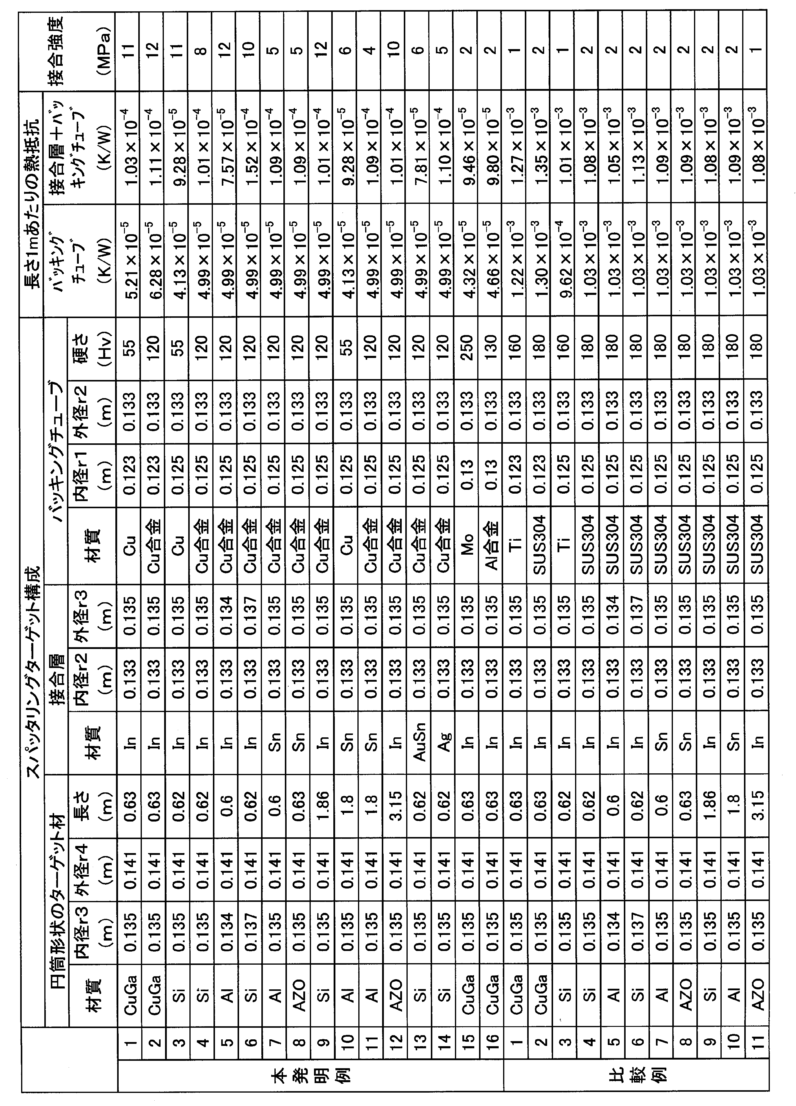
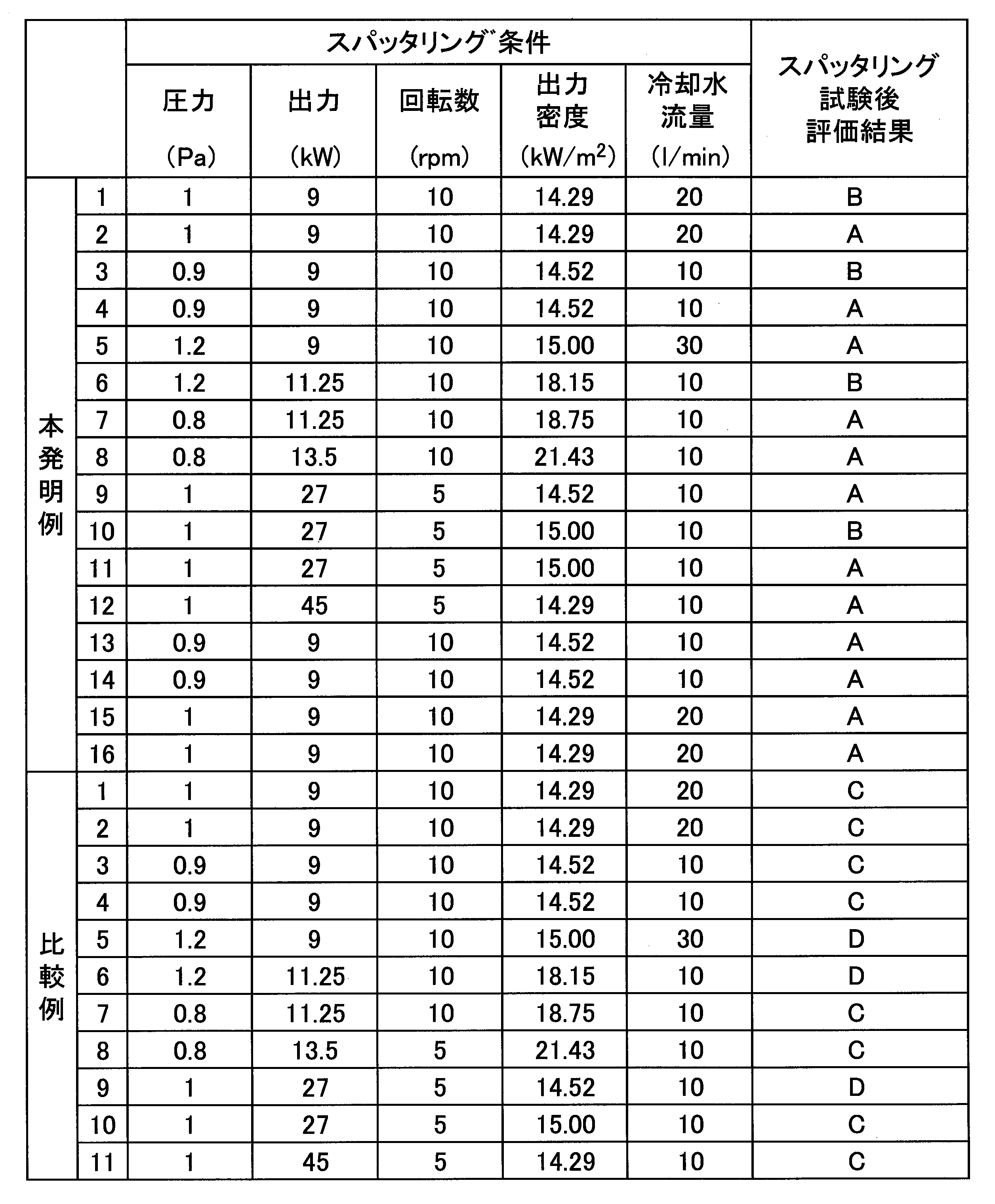
バッキングチューブにおける径方向の熱抵抗が本発明よりも大きい比較例については、スパッタリング試験の結果、接合層の溶け出しが確認された。
これに対して、バッキングチューブにおける径方向の熱抵抗が本発明の範囲内とされた本発明例においては、接合層の溶け出しが抑制されていた。
また、本発明例においては、接合層とバッキングチューブとの接合強度が4MPa以上とされており、スパッタリングターゲット材とバッキングチューブとが接合層を介して確実に接合されていることが確認された。
なお、バッキングチューブの硬さを100Hv以上としたものでは、特に接合層の溶け出しが抑制されていた。
これに対して、バッキングチューブにおける径方向の熱抵抗が本発明の範囲内とされた本発明例においては、接合層の溶け出しが抑制されていた。
また、本発明例においては、接合層とバッキングチューブとの接合強度が4MPa以上とされており、スパッタリングターゲット材とバッキングチューブとが接合層を介して確実に接合されていることが確認された。
なお、バッキングチューブの硬さを100Hv以上としたものでは、特に接合層の溶け出しが抑制されていた。
本発明の円筒型スパッタリングターゲットによれば、スパッタ時のパワー密度を高く設定した場合や、使用によりエロ―ジョンが進行した場合であっても、接合層の溶け出しを抑制することができ、安定して成膜を行うことが可能である。
10 円筒型スパッタリングターゲット
11 円筒形状のスパッタリングターゲット材
12 バッキングチューブ
13 接合層
11 円筒形状のスパッタリングターゲット材
12 バッキングチューブ
13 接合層
Claims (5)
- 円筒形状をなすスパッタリングターゲット材と、このスパッタリングターゲット材の内周側に接合層を介して接合されたバッキングチューブと、を備えた円筒型スパッタリングターゲットであって、
前記バッキングチューブにおける径方向の熱抵抗が6.5×10⁻⁵K/W以下であることを特徴とする円筒型スパッタリングターゲット。 - 前記接合層の外周面から前記バッキングチューブの内周面までの径方向の熱抵抗が1.2×10⁻⁴K/W以下であることを特徴とする請求項1に記載の円筒型スパッタリングターゲット。
- 前記接合層と前記バッキングチューブとの接合強度が4MPa以上であることを特徴とする請求項1又は請求項2に記載の円筒型スパッタリングターゲット。
- 前記バッキングチューブは、ビッカース硬さが100Hv以上であることを特徴とする請求項1から請求項3のいずれか一項に記載の円筒型スパッタリングターゲット。
- 前記バッキングチューブは、銅合金で構成されていることを特徴とする請求項1から請求項4のいずれか一項に記載の円筒型スパッタリングターゲット。
Priority Applications (3)
| Application Number | Priority Date | Filing Date | Title |
|---|---|---|---|
| PCT/JP2017/032230 WO2019049254A1 (ja) | 2017-09-07 | 2017-09-07 | 円筒型スパッタリングターゲット |
| CN201780093699.2A CN111032904A (zh) | 2017-09-07 | 2017-09-07 | 圆筒型溅射靶 |
| KR1020207003482A KR102357819B1 (ko) | 2017-09-07 | 2017-09-07 | 원통형 스퍼터링 타깃 |
Applications Claiming Priority (1)
| Application Number | Priority Date | Filing Date | Title |
|---|---|---|---|
| PCT/JP2017/032230 WO2019049254A1 (ja) | 2017-09-07 | 2017-09-07 | 円筒型スパッタリングターゲット |
Publications (1)
| Publication Number | Publication Date |
|---|---|
| WO2019049254A1 true WO2019049254A1 (ja) | 2019-03-14 |
Family
ID=65633715
Family Applications (1)
| Application Number | Title | Priority Date | Filing Date |
|---|---|---|---|
| PCT/JP2017/032230 Ceased WO2019049254A1 (ja) | 2017-09-07 | 2017-09-07 | 円筒型スパッタリングターゲット |
Country Status (3)
| Country | Link |
|---|---|
| KR (1) | KR102357819B1 (ja) |
| CN (1) | CN111032904A (ja) |
| WO (1) | WO2019049254A1 (ja) |
Cited By (1)
| Publication number | Priority date | Publication date | Assignee | Title |
|---|---|---|---|---|
| CN111286704A (zh) * | 2020-04-13 | 2020-06-16 | 合肥江丰电子材料有限公司 | 一种便于与设备连接的一体型旋转靶材 |
Citations (6)
| Publication number | Priority date | Publication date | Assignee | Title |
|---|---|---|---|---|
| JPH10110226A (ja) * | 1996-10-08 | 1998-04-28 | Dowa Mining Co Ltd | 銅または銅合金の製造方法 |
| JPH10168532A (ja) * | 1996-10-08 | 1998-06-23 | Dowa Mining Co Ltd | バッキングプレート用銅合金およびその製造方法 |
| JP2012162759A (ja) * | 2011-02-04 | 2012-08-30 | Sumitomo Metal Mining Co Ltd | 円筒形スパッタリングターゲット |
| JP2015012101A (ja) * | 2013-06-28 | 2015-01-19 | 株式会社リコー | 光学モジュール、光走査装置、画像形成装置、及び光学モジュールの製造方法 |
| JP2017131541A (ja) * | 2016-01-29 | 2017-08-03 | セイコーエプソン株式会社 | 熱流センサー及び検出単位体 |
| JP2017190523A (ja) * | 2016-04-12 | 2017-10-19 | 三菱マテリアル株式会社 | 円筒型スパッタリングターゲット |
Family Cites Families (4)
| Publication number | Priority date | Publication date | Assignee | Title |
|---|---|---|---|---|
| JPH0539566A (ja) * | 1991-02-19 | 1993-02-19 | Mitsubishi Materials Corp | スパツタリング用ターゲツト及びその製造方法 |
| JP6089983B2 (ja) | 2012-07-18 | 2017-03-08 | 三菱マテリアル株式会社 | 円筒形スパッタリングターゲットおよびその製造方法 |
| CN105624622B (zh) * | 2014-11-26 | 2018-02-09 | 宁波江丰电子材料股份有限公司 | 靶材组件的制造方法 |
| JP5887625B1 (ja) * | 2015-03-27 | 2016-03-16 | Jx金属株式会社 | 円筒型スパッタリングターゲット、円筒型焼結体、円筒型成形体及びそれらの製造方法 |
-
2017
- 2017-09-07 KR KR1020207003482A patent/KR102357819B1/ko active Active
- 2017-09-07 WO PCT/JP2017/032230 patent/WO2019049254A1/ja not_active Ceased
- 2017-09-07 CN CN201780093699.2A patent/CN111032904A/zh active Pending
Patent Citations (6)
| Publication number | Priority date | Publication date | Assignee | Title |
|---|---|---|---|---|
| JPH10110226A (ja) * | 1996-10-08 | 1998-04-28 | Dowa Mining Co Ltd | 銅または銅合金の製造方法 |
| JPH10168532A (ja) * | 1996-10-08 | 1998-06-23 | Dowa Mining Co Ltd | バッキングプレート用銅合金およびその製造方法 |
| JP2012162759A (ja) * | 2011-02-04 | 2012-08-30 | Sumitomo Metal Mining Co Ltd | 円筒形スパッタリングターゲット |
| JP2015012101A (ja) * | 2013-06-28 | 2015-01-19 | 株式会社リコー | 光学モジュール、光走査装置、画像形成装置、及び光学モジュールの製造方法 |
| JP2017131541A (ja) * | 2016-01-29 | 2017-08-03 | セイコーエプソン株式会社 | 熱流センサー及び検出単位体 |
| JP2017190523A (ja) * | 2016-04-12 | 2017-10-19 | 三菱マテリアル株式会社 | 円筒型スパッタリングターゲット |
Cited By (1)
| Publication number | Priority date | Publication date | Assignee | Title |
|---|---|---|---|---|
| CN111286704A (zh) * | 2020-04-13 | 2020-06-16 | 合肥江丰电子材料有限公司 | 一种便于与设备连接的一体型旋转靶材 |
Also Published As
| Publication number | Publication date |
|---|---|
| CN111032904A (zh) | 2020-04-17 |
| KR102357819B1 (ko) | 2022-02-08 |
| KR20200051581A (ko) | 2020-05-13 |
Similar Documents
| Publication | Publication Date | Title |
|---|---|---|
| US20110132973A1 (en) | Method of manufacturing high-heat-load equipment by metallurgically joining carbon material with copper-alloy material | |
| WO2017164013A1 (ja) | ベーパチャンバーの製造方法 | |
| KR101979531B1 (ko) | 방열 부품용 구리 합금판 및 방열 부품 | |
| JP6446011B2 (ja) | 放熱部品用銅合金板及び放熱部品 | |
| JPWO2014030362A1 (ja) | インジウム製円筒型スパッタリングターゲット及びその製造方法 | |
| JP2015193937A (ja) | スパッタリングターゲットの構成要素の接合方法、スパッタリングターゲットの構成要素の接合アセンブリ、および接合アセンブリの使用 | |
| JP2018162518A (ja) | ベーパーチャンバー用銅合金板及びベーパーチャンバー | |
| WO2018066414A1 (ja) | 放熱部品用銅合金板、放熱部品、及び放熱部品の製造方法 | |
| JP6732840B2 (ja) | ベーパーチャンバー用銅合金板 | |
| WO2018062255A1 (ja) | 放熱部品用銅合金板、放熱部品、及び放熱部品の製造方法 | |
| WO2016152648A1 (ja) | 放熱部品用銅合金板及び放熱部品 | |
| WO2019049254A1 (ja) | 円筒型スパッタリングターゲット | |
| TWI751304B (zh) | 圓筒型濺鍍靶之製造方法及圓筒型濺鍍靶 | |
| JP6756283B2 (ja) | 円筒型スパッタリングターゲット | |
| US20190119786A1 (en) | Copper alloy backing tube and method of manufacturing copper alloy backing tube | |
| JP6332078B2 (ja) | 円筒形スパッタリングターゲットの製造方法 | |
| TWI746634B (zh) | 圓筒型濺鍍靶 | |
| JP2018135590A (ja) | 円筒形スパッタリングターゲット、焼結体及び円筒形スパッタリングターゲットの製造方法 | |
| JP2021055120A (ja) | 円筒形スパッタリングターゲット及びその製造方法 | |
| WO2020031631A1 (ja) | 円筒型スパッタリングターゲット、In系はんだ材、及び、円筒型スパッタリングターゲットの製造方法 | |
| KR101937526B1 (ko) | 원통형 스퍼터링 타겟 | |
| KR102901294B1 (ko) | 방전 램프 | |
| KR20180004723A (ko) | 관형 타겟 | |
| JP2014214317A (ja) | ターゲット材のボンディング方法、スパッタリングターゲットの製造方法及びスパッタリングターゲット | |
| JP2020200491A (ja) | 円筒型スパッタリングターゲット、及び、円筒型スパッタリングターゲットの製造方法 |
Legal Events
| Date | Code | Title | Description |
|---|---|---|---|
| 121 | Ep: the epo has been informed by wipo that ep was designated in this application |
Ref document number: 17924020 Country of ref document: EP Kind code of ref document: A1 |
|
| NENP | Non-entry into the national phase |
Ref country code: DE |
|
| 122 | Ep: pct application non-entry in european phase |
Ref document number: 17924020 Country of ref document: EP Kind code of ref document: A1 |
|
| NENP | Non-entry into the national phase |
Ref country code: JP |