WO2019044403A1 - 太陽光発電システム、パワーコンディショナ - Google Patents
太陽光発電システム、パワーコンディショナ Download PDFInfo
- Publication number
- WO2019044403A1 WO2019044403A1 PCT/JP2018/029444 JP2018029444W WO2019044403A1 WO 2019044403 A1 WO2019044403 A1 WO 2019044403A1 JP 2018029444 W JP2018029444 W JP 2018029444W WO 2019044403 A1 WO2019044403 A1 WO 2019044403A1
- Authority
- WO
- WIPO (PCT)
- Prior art keywords
- converter
- voltage
- power
- relay
- control circuit
- Prior art date
- Legal status (The legal status is an assumption and is not a legal conclusion. Google has not performed a legal analysis and makes no representation as to the accuracy of the status listed.)
- Ceased
Links
Images




Classifications
-
- G—PHYSICS
- G05—CONTROLLING; REGULATING
- G05F—SYSTEMS FOR REGULATING ELECTRIC OR MAGNETIC VARIABLES
- G05F1/00—Automatic systems in which deviations of an electric quantity from one or more predetermined values are detected at the output of the system and fed back to a device within the system to restore the detected quantity to its predetermined value or values, i.e. retroactive systems
- G05F1/66—Regulating electric power
- G05F1/67—Regulating electric power to the maximum power available from a generator, e.g. from solar cell
-
- H—ELECTRICITY
- H02—GENERATION; CONVERSION OR DISTRIBUTION OF ELECTRIC POWER
- H02J—ELECTRIC POWER NETWORKS; CIRCUIT ARRANGEMENTS OR SYSTEMS FOR SUPPLYING OR DISTRIBUTING ELECTRIC POWER; SYSTEMS FOR STORING ELECTRIC ENERGY
- H02J3/00—Circuit arrangements for AC mains or AC distribution networks
- H02J3/007—Arrangements for selectively connecting one or more loads to one or more power sources or power lines
-
- G—PHYSICS
- G05—CONTROLLING; REGULATING
- G05F—SYSTEMS FOR REGULATING ELECTRIC OR MAGNETIC VARIABLES
- G05F1/00—Automatic systems in which deviations of an electric quantity from one or more predetermined values are detected at the output of the system and fed back to a device within the system to restore the detected quantity to its predetermined value or values, i.e. retroactive systems
- G05F1/66—Regulating electric power
-
- H—ELECTRICITY
- H02—GENERATION; CONVERSION OR DISTRIBUTION OF ELECTRIC POWER
- H02J—ELECTRIC POWER NETWORKS; CIRCUIT ARRANGEMENTS OR SYSTEMS FOR SUPPLYING OR DISTRIBUTING ELECTRIC POWER; SYSTEMS FOR STORING ELECTRIC ENERGY
- H02J3/00—Circuit arrangements for AC mains or AC distribution networks
- H02J3/38—Arrangements for feeding a single network from two or more generators or sources in parallel; Arrangements for feeding already energised networks from additional generators or sources in parallel
-
- H—ELECTRICITY
- H02—GENERATION; CONVERSION OR DISTRIBUTION OF ELECTRIC POWER
- H02J—ELECTRIC POWER NETWORKS; CIRCUIT ARRANGEMENTS OR SYSTEMS FOR SUPPLYING OR DISTRIBUTING ELECTRIC POWER; SYSTEMS FOR STORING ELECTRIC ENERGY
- H02J3/00—Circuit arrangements for AC mains or AC distribution networks
- H02J3/38—Arrangements for feeding a single network from two or more generators or sources in parallel; Arrangements for feeding already energised networks from additional generators or sources in parallel
- H02J3/381—Dispersed generators
-
- H—ELECTRICITY
- H02—GENERATION; CONVERSION OR DISTRIBUTION OF ELECTRIC POWER
- H02J—ELECTRIC POWER NETWORKS; CIRCUIT ARRANGEMENTS OR SYSTEMS FOR SUPPLYING OR DISTRIBUTING ELECTRIC POWER; SYSTEMS FOR STORING ELECTRIC ENERGY
- H02J3/00—Circuit arrangements for AC mains or AC distribution networks
- H02J3/38—Arrangements for feeding a single network from two or more generators or sources in parallel; Arrangements for feeding already energised networks from additional generators or sources in parallel
- H02J3/40—Synchronisation of generators for connection to a network or to another generator
- H02J3/42—Synchronisation of generators for connection to a network or to another generator with automatic parallel connection when synchronisation is achieved
-
- H—ELECTRICITY
- H02—GENERATION; CONVERSION OR DISTRIBUTION OF ELECTRIC POWER
- H02M—APPARATUS FOR CONVERSION BETWEEN AC AND AC, BETWEEN AC AND DC, OR BETWEEN DC AND DC, AND FOR USE WITH MAINS OR SIMILAR POWER SUPPLY SYSTEMS; CONVERSION OF DC OR AC INPUT POWER INTO SURGE OUTPUT POWER; CONTROL OR REGULATION THEREOF
- H02M3/00—Conversion of DC power input into DC power output
- H02M3/02—Conversion of DC power input into DC power output without intermediate conversion into AC
- H02M3/04—Conversion of DC power input into DC power output without intermediate conversion into AC by static converters
- H02M3/10—Conversion of DC power input into DC power output without intermediate conversion into AC by static converters using discharge tubes with control electrode or semiconductor devices with control electrode
- H02M3/145—Conversion of DC power input into DC power output without intermediate conversion into AC by static converters using discharge tubes with control electrode or semiconductor devices with control electrode using devices of a triode or transistor type requiring continuous application of a control signal
- H02M3/155—Conversion of DC power input into DC power output without intermediate conversion into AC by static converters using discharge tubes with control electrode or semiconductor devices with control electrode using devices of a triode or transistor type requiring continuous application of a control signal using semiconductor devices only
-
- H—ELECTRICITY
- H02—GENERATION; CONVERSION OR DISTRIBUTION OF ELECTRIC POWER
- H02M—APPARATUS FOR CONVERSION BETWEEN AC AND AC, BETWEEN AC AND DC, OR BETWEEN DC AND DC, AND FOR USE WITH MAINS OR SIMILAR POWER SUPPLY SYSTEMS; CONVERSION OF DC OR AC INPUT POWER INTO SURGE OUTPUT POWER; CONTROL OR REGULATION THEREOF
- H02M7/00—Conversion of AC power input into DC power output; Conversion of DC power input into AC power output
- H02M7/42—Conversion of DC power input into AC power output without possibility of reversal
- H02M7/44—Conversion of DC power input into AC power output without possibility of reversal by static converters
- H02M7/48—Conversion of DC power input into AC power output without possibility of reversal by static converters using discharge tubes with control electrode or semiconductor devices with control electrode
-
- H—ELECTRICITY
- H02—GENERATION; CONVERSION OR DISTRIBUTION OF ELECTRIC POWER
- H02S—GENERATION OF ELECTRIC POWER BY CONVERSION OF INFRARED RADIATION, VISIBLE LIGHT OR ULTRAVIOLET LIGHT, e.g. USING PHOTOVOLTAIC [PV] MODULES
- H02S40/00—Components or accessories in combination with PV modules, not provided for in groups H02S10/00 - H02S30/00
- H02S40/30—Electrical components
- H02S40/32—Electrical components comprising DC/AC inverter means associated with the PV module itself, e.g. AC modules
-
- H—ELECTRICITY
- H02—GENERATION; CONVERSION OR DISTRIBUTION OF ELECTRIC POWER
- H02J—ELECTRIC POWER NETWORKS; CIRCUIT ARRANGEMENTS OR SYSTEMS FOR SUPPLYING OR DISTRIBUTING ELECTRIC POWER; SYSTEMS FOR STORING ELECTRIC ENERGY
- H02J2101/00—Supply or distribution of decentralised, dispersed or local electric power generation
- H02J2101/20—Dispersed power generation using renewable energy sources
- H02J2101/22—Solar energy
- H02J2101/24—Photovoltaics
-
- H—ELECTRICITY
- H02—GENERATION; CONVERSION OR DISTRIBUTION OF ELECTRIC POWER
- H02J—ELECTRIC POWER NETWORKS; CIRCUIT ARRANGEMENTS OR SYSTEMS FOR SUPPLYING OR DISTRIBUTING ELECTRIC POWER; SYSTEMS FOR STORING ELECTRIC ENERGY
- H02J2101/00—Supply or distribution of decentralised, dispersed or local electric power generation
- H02J2101/20—Dispersed power generation using renewable energy sources
- H02J2101/22—Solar energy
- H02J2101/24—Photovoltaics
- H02J2101/25—Photovoltaics involving maximum power point tracking control for photovoltaic sources
-
- Y—GENERAL TAGGING OF NEW TECHNOLOGICAL DEVELOPMENTS; GENERAL TAGGING OF CROSS-SECTIONAL TECHNOLOGIES SPANNING OVER SEVERAL SECTIONS OF THE IPC; TECHNICAL SUBJECTS COVERED BY FORMER USPC CROSS-REFERENCE ART COLLECTIONS [XRACs] AND DIGESTS
- Y02—TECHNOLOGIES OR APPLICATIONS FOR MITIGATION OR ADAPTATION AGAINST CLIMATE CHANGE
- Y02E—REDUCTION OF GREENHOUSE GAS [GHG] EMISSIONS, RELATED TO ENERGY GENERATION, TRANSMISSION OR DISTRIBUTION
- Y02E10/00—Energy generation through renewable energy sources
- Y02E10/50—Photovoltaic [PV] energy
- Y02E10/56—Power conversion systems, e.g. maximum power point trackers
Definitions
- the present invention relates to a solar power generation system and a power conditioner.
- a power conditioner to which a solar panel is connected has an inverter unit that converts DC power of the solar panel into AC power, and a grid connection relay that supplies AC power to an indoor AC load.
- the driving power of the power conditioner may be obtained from a commercial power system, it is desirable to obtain it from the output power of the solar panel in consideration of self-sustaining operation or the like at the time of a disaster.
- the activated power conditioner closes (turns on) the grid interconnection relay that is switched on when linking to the commercial power grid, and supplies AC power to the indoor AC load.
- the grid connection relay opens (turns off).
- the power conditioner In the time zone such as sunrise, since the solar panel power generation is almost zero since it is at night until then, the power conditioner is stopped and the grid connection relay is open (off), When the sun starts to hit the solar panel with the sunrise, power generation gradually starts.
- the open-circuit voltage of the solar panel exceeds a certain value, the power conditioner starts to start.
- the output voltage of the solar panel is started by the start of the power conditioner Is lower than the voltage required for the operation of the power conditioner, and the power conditioner stops.
- the power conditioner stops the output voltage of the solar panel rises to the open circuit voltage, so the power conditioner starts up again. Therefore, when the output power of the solar panel is insufficient, the power conditioner repeats start and stop.
- the power conditioner will be activated needlessly.
- the relay for grid interconnection wastefully repeats the closing operation and the opening operation even though it is not linked with the commercial power system.
- Such useless switching operation shortens noise generation and mechanical life in the grid interconnection relay.
- the start determination is performed using the resistive load as described above, if the resistance value of the resistive load is small, the efficiency is lowered, so it is preferable that the resistance value is large.
- the resistance value of the resistive load is small, the efficiency is lowered, so it is preferable that the resistance value is large.
- the DC voltage value when power is consumed becomes small, the start determination becomes unstable, and there is also a possibility of starting uselessly.
- the wasteful start and stop of the power conditioner leads to wasteful opening and closing operation of the grid interconnection relay, thereby reducing the generation of noise and mechanical life of the grid interconnection relay.
- An object of the present invention is to provide a solar power generation system and a power conditioner that can suppress unnecessary start.
- a solar power generation system includes: a solar panel; a PV converter connected to the solar panel; an inverter converting a DC voltage output from the PV converter into an AC voltage; A first relay for connecting and separating a first AC load for supplying the AC voltage, a controller for controlling the PV converter and the inverter, and a DC voltage output from the PV converter as the controller And the control unit varies the impedance of the DC-DC converter in the start-up process, and the input voltage and the input current of the PV converter, or the PV converter Output voltage and output current, and it is determined whether or not at least the first relay is to be closed according to their values.
- the load on the solar panel that is, the power consumption on the solar panel changes.
- the output characteristics (current-voltage (IV) characteristics) of the solar panel are unique to the solar panel.
- the current-voltage (IV) characteristics change (the output current of the solar panel, the output voltage) depending on the solar radiation intensity to the solar panel. Therefore, when a desired output characteristic is obtained, it can be determined whether or not the operation of the entire power conditioner is possible by the generated power of the solar panel at that time. Therefore, it is useless to detect the input voltage and input current of the PV converter when the impedance of the DC-DC converter is varied, and to determine whether to close the first relay based on those values.
- the start-up can be suppressed, and unnecessary opening and closing of the first relay can be suppressed.
- the first AC load is also connected to a power system.
- the photovoltaic power generation system by interconnecting the photovoltaic power generation system into the power system, if the amount of power generation of the solar panel exceeds the power required by the first alternating current load, reverse power flow to the power system By doing this, there is no waste of surplus power.
- the inverter includes a second relay for connecting and separating a second AC load that supplies the AC voltage.
- the inverter includes a second relay for connecting and separating a second AC load that supplies the AC voltage.
- the control unit estimates the generated power of the solar panel from the input voltage and the input current of the PV converter, or the output voltage and the output current of the PV converter, and the estimated generated power It is preferable to determine whether or not the first relay or the second relay is to be closed by comparing the second power with the drivable power.
- the current-voltage (IV) characteristic of the solar panel can be calculated by detecting the input voltage and the input current of the PV converter, that is, the output voltage and the output current of the solar panel.
- the generated power of the solar panel can be estimated by this current-voltage (IV) characteristic. If the estimated generated power of the solar panel is lower than the operable power, it is determined not to close the first relay or the second relay, that is, keep the open state. Therefore, it is possible to suppress the useless start of the power conditioner and to suppress the useless opening and closing of the first relay or the second relay.
- the control unit includes a main control circuit that executes the start-up process, a first control circuit that controls the PV converter, and a second control circuit that controls the inverter.
- a DC-DC converter includes a main conversion unit generating a drive voltage of the main control circuit, a first conversion unit generating a drive voltage of the first control circuit, and a drive voltage of the second control circuit.
- the main control circuit controls the operation / stop of the first converter and the second converter, and at least the operation / stop of the first converter is performed in the activation process. It is preferable to control to change the impedance of the DC-DC converter.
- the generated power of the solar panel can be determined by varying the impedance of the DC-DC converter by the operation / stop of the first conversion unit. Then, by controlling the operation / stop of the first conversion unit and the second conversion unit, the amount of change in impedance of the DC-DC converter can be increased, and the estimation accuracy of the generated power of the solar panel can be increased. Become.
- a bidirectional DC-DC converter having a first end connected to a DC voltage bus between the PV converter and the inverter, and a second end of the bidirectional DC-DC converter It is preferable that the power storage device of
- the bidirectional DC-DC converter when the generated power of the solar panel is lower than the operable power of the power conditioner, the bidirectional DC-DC converter is operated to operate the inverter with the discharge voltage from the storage device. Then, the AC voltage can be supplied to the load by converting the discharge voltage from the power storage device into an AC voltage by the inverter.
- the control unit stops the PV converter and operates the bidirectional DC-DC converter to operate the power storage device. It is preferable to output a DC voltage based on the stored voltage to the DC voltage bus.
- the bidirectional DC-DC converter when the generated power of the solar panel is lower than the operable power of the power conditioner, the bidirectional DC-DC converter is operated to operate the inverter with the discharge voltage from the storage device. Then, the AC voltage can be supplied to the load by converting the discharge voltage from the power storage device into an AC voltage by the inverter.
- a power conditioner is a power conditioner that converts a DC voltage input from a solar panel into an AC voltage and outputs the AC voltage to a first AC load, and is connected to the solar panel
- a PV converter an inverter for converting a DC voltage output from the PV converter into an AC voltage
- a first relay for connecting and separating the first AC load from the inverter, the PV converter, and the inverter
- the control unit includes: a control unit to control; and a DC-DC converter to convert a DC voltage output from the PV converter into a drive voltage for the control unit. Vary the impedance and check the input voltage and input current of the PV converter or the output voltage and output current of the PV converter And, determining at least the first relay whether the closed state according to their values.
- the load on the solar panel that is, the power consumption on the solar panel changes.
- the output characteristics (current-voltage (IV) characteristics) of the solar panel are unique to the solar panel.
- the current-voltage (IV) characteristic changes (the output current of the solar panel, the output voltage) according to the solar radiation intensity to the solar panel. Therefore, when a desired output characteristic is obtained, it can be determined whether or not the operation of the entire power conditioner is possible by the generated power of the solar panel at that time. Therefore, it is useless to detect the input voltage and input current of the PV converter when the impedance of the DC-DC converter is varied, and to determine whether to close the first relay based on those values.
- the start-up can be suppressed, and unnecessary opening and closing of the first relay can be suppressed.
- the first AC load is also connected to a power system.
- the operation instead of operating in a completely disconnected state (off grid) from the electric power system, the operation is always performed as an interconnected operation connected to the electric power system, and the operation of the power conditioner is stopped at the time of a power failure. become.
- the inverter includes a second relay for connecting and separating a second AC load for supplying the AC voltage.
- the grid connection operation is performed, and at the time of a power failure, the first relay corresponding to the grid connection relay is opened to shut off the grid connection to perform the self-sustaining operation.
- the second AC load can be operated by closing the second relay.
- the second alternating current load is preferably connected to a stand-alone operation dedicated outlet connected to the second relay, and can receive power generated by itself from a separate port called the stand-alone operation dedicated outlet.
- the power conditioner preferably includes a bi-directional DC-DC converter having a first end connected to a direct current voltage bus between the PV converter and the inverter, and a power storage device connected to a second end.
- the bidirectional DC-DC converter when the generated power of the solar panel is lower than the operable power of the power conditioner, the bidirectional DC-DC converter is operated to operate the inverter with the discharge voltage from the storage device. Then, the AC voltage can be supplied to the load by converting the discharge voltage from the power storage device into an AC voltage by the inverter.
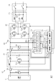
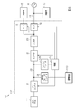
- BRIEF DESCRIPTION OF THE DRAWINGS The schematic circuit diagram which shows the power conditioner of 1st Embodiment.
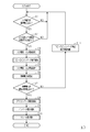
- the flowchart which shows the starting process of a control circuit.
- (A) is a current-voltage (IV) characteristic view of a solar panel
- (b) is a power-voltage (PV) characteristic view of the solar panel. Explanatory drawing of the electric power-voltage (PV) characteristic of the solar panel with respect to sunlight intensity.
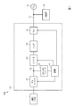
- the schematic circuit diagram which shows the power conditioner of 2nd Embodiment.
- the solar power generation system 10 of the present embodiment includes a solar panel 11 and a power conditioner 12 connected to the solar panel 11.
- the power conditioner 12 is connected to the commercial power system 14 via the power line 13.
- the commercial power system 14 is a distribution system in which a power company transmits power.
- a first AC load 15 is connected to the power line 13.
- the first AC load 15 is, for example, an indoor load connected to a distribution board.
- the indoor load includes, for example, lighting equipment, refrigerators, washing machines, air conditioners, microwave ovens, and other household electrical appliances.
- a second AC load 16 is connected to the power conditioner 12.
- the second AC load 16 is a load selected in advance among the electrical devices, and may be an electrical device such as lighting.
- the second alternating current load 16 may be an electric device such as a refrigerator connected to a stand-alone operation outlet (not shown) connected to the power conditioner 12.
- the first alternating current load 15 and the second alternating current load 16 described above may be electrical equipment in a commercial facility or factory.
- the power conditioner 12 converts DC power generated by the solar panel 11 into AC power and outputs it. And the power conditioner 12 connects or disconnects the solar panel 11 and the commercial power grid 14.
- the power conditioner 12 includes a PV converter 21, an inverter 22, a filter 23, a first relay (simply referred to as “relay”) 24 corresponding to a grid interconnection relay, and a second relay (same as a stand-alone grid relay) It has simply a “relay”) 25, a DC-DC converter 26, and a control unit 27.
- the PV converter 21, the inverter 22 and the DC-DC converter 26 are connected to one another via a DC voltage bus 28.
- the control unit 27 controls the PV converter 21, the inverter 22, the first relay 24, and the second relay 25.
- the PV converter 21 is a step-up chopper circuit that operates according to a control signal from the control unit 27, and boosts and outputs a DC voltage input from the solar panel 11.
- the inverter 22 is a direct current to alternating current conversion circuit operated by a control signal from the control unit 27, and converts the output voltage of the PV converter 21 into an alternating current voltage.
- the filter 23 reduces high frequency components of the AC power output from the inverter 22.
- the DC-DC converter 26 is, for example, a step-down circuit, and converts the DC voltage of the DC voltage bus 28 into a DC voltage suitable for the operation of the control unit 27.
- the control unit 27 operates based on the DC voltage supplied from the DC-DC converter 26, and controls the PV converter 21, the inverter 22, the first relay 24, and the second relay 25.
- the first relay 24 is, for example, a normally open electromagnetic relay, and the control unit 27 controls the closed state and the open state according to a control signal.
- the first relay 24 brings the first AC load 15 into and out of contact with the inverter 22.
- the closing operation of the first relay 24 interconnects the solar power generation system 10 (the solar panel 11) and the commercial power grid 14, and the opening operation of the first relay 24 disconnects the parallel connection.
- the second relay 25 is, for example, a normally-opened electromagnetic relay, and the control unit 27 controls the closed state and the open state according to a control signal.
- the second relay 25 brings the second AC load 16 into and out of contact with the inverter 22.
- the power conditioner 12 (control unit 27) enables the self-sustaining operation of operating the second AC load 16 by the generated power of the solar panel 11 by the closing operation of the second relay 25.
- the power conditioner 12 (control part 27) open-operates the 1st relay 24 (off).
- Control unit 27 determines whether or not the commercial power system 14 has a power failure.
- the power line 13 is provided with a voltage sensor (not shown), and the control unit 27 determines whether the commercial power system 14 has a power failure based on the detection result of the power sensor.
- Control unit 27 executes switching control to switch between grid-connected operation and self-sustaining operation based on whether or not commercial power system 14 has a power failure.
- the control unit 27 performs an interconnection operation when the commercial power system 14 does not have a power failure, and switches the interconnection operation to a standalone operation when the commercial power system 14 has a power failure.
- the control unit 27 switches from the autonomous operation to the interconnection operation.
- the control unit 27 controls the first relay 24 so that the power conditioner 12 and the commercial power grid 14 are disconnected when switching from the interconnection operation to the autonomous operation, and the second relay 25 is closed. Set to the ready state.
- the control unit 27 controls the first relay 24 to connect the power conditioner 12 and the commercial power grid 14 when switching from the stand-alone operation to the interconnection operation, and opens the second relay 25. Put in a state.
- the positive electrode terminal and the negative electrode terminal of the solar panel 11 are connected to the PV converter 21.
- the output terminal of the PV converter 21 is connected to the high voltage side wire 28 a and the low voltage side wire 28 b of the DC voltage bus 28.
- the PV converter 21 includes an inductor L11, a transistor T11, a diode D11, and a smoothing capacitor C11.
- the first terminal of the inductor L11 is connected to the positive electrode terminal of the solar panel 11, and the second terminal of the inductor L11 is connected to the transistor T11 and the anode of the diode D11.
- the cathode of the diode D11 is connected to the first terminal of the smoothing capacitor C11.
- an aluminum electrolytic capacitor or a tantalum electrolytic capacitor is used as the smoothing capacitor C11.
- the transistor T11 is, for example, an N-channel MOSFET (Metal-Oxide-Semiconductor Field-Effect Transistor).
- the inductor L11 is connected to the drain terminal of the transistor T11, and the source terminal of the transistor T11 is connected to the negative electrode terminal of the solar panel 11 and the second terminal of the smoothing capacitor C11.
- the transistor T11 may be an insulated gate bipolar transistor (IGBT) or the like.
- the PV converter 21 outputs the second DC voltage obtained by boosting the first DC voltage input from the solar panel 11 to the DC voltage bus 28 by turning on and off the transistor T11 according to the control signal.
- the smoothing capacitor C11 smoothes the second DC voltage, that is, the output voltage of the PV converter 21.
- Inverter 22 includes transistors T21, T22, T23, and T24.
- the transistors T21 to T24 are, for example, N-channel MOSFETs. An IGBT or the like may be used as the transistors T21 to T24.
- the drain terminals of the transistors T21 and T22 are connected to the high voltage side wire 28a, the source terminals of the transistors T21 and T22 are connected to the drain terminals of the transistors T23 and T24, and the source terminals of the transistors T23 and T24 are connected to the low voltage side wire 28b ing.
- a connection point between the source terminal of the transistor T21 and the drain terminal of the transistor T23 and a connection point between the source terminal of the transistor T22 and the drain terminal of the transistor T24 are connected to the filter 23.
- the filter 23 includes inductors L21 and L22 and a capacitor C21.
- the filter 23 attenuates the high frequency component of the AC power output from the inverter 22 and brings the output voltage and the output current of the inverter 22 closer to a sine wave.
- a first relay 24 and a second relay 25 are connected to the filter 23.
- the power conditioner 12 has voltage sensors 31, 33 and current sensors 32, 34.
- the voltage sensor 31 is provided between the input terminals of the PV converter 21.
- the voltage sensor 31 is provided to detect the input voltage of the PV converter 21.
- Voltage sensor 31 outputs a signal corresponding to the input voltage of PV converter 21 to control unit 27.
- the current sensor 32 is provided, for example, between the positive electrode terminal of the solar panel 11 and the PV converter 21.
- the current sensor 32 is provided to detect the input current of the PV converter 21.
- the current sensor 32 outputs a signal corresponding to the input current of the PV converter 21 to the control unit 27.
- the voltage sensor 33 is provided on the DC voltage bus 28.
- the voltage sensor 33 is connected between the high voltage side wire 28 a and the low voltage side wire 28 b of the DC voltage bus 28.
- the voltage sensor 33 outputs a signal corresponding to the voltage of the DC voltage bus 28 to the control unit 27.
- the current sensor 34 is provided, for example, on the high voltage side wire 28 a of the direct current voltage bus 28.
- the current sensor 34 is provided to detect the output current of the PV converter 21.
- the current sensor 34 outputs a signal corresponding to the output current of the PV converter 21 to the control unit 27.
- the control unit 27 of the present embodiment includes a plurality of (three in the present embodiment) control circuits 27a, 27b and 27c.
- the DC-DC converter 26 includes three DC-DC converters 26a, 26b, 26c corresponding to the control circuits 27a, 27b, 27c.
- control circuit 27a is a manager circuit that controls the entire power conditioner.
- the control circuit 27 b is a circuit that controls the PV converter 21.
- the control circuit 27 c is a circuit that controls the inverter 22.
- the DC-DC converters 26a to 26c are, for example, isolated step-down circuits.
- the DC-DC converter 26a operates at all times, and supplies a drive voltage obtained by stepping down the DC voltage of the DC voltage bus 28 to the control circuit 27a.
- the DC-DC converters 26b and 26c are controlled in operation / stop by the control circuit 27a.
- the operated DC-DC converters 26b and 26c supply the control circuits 27b and 27c with drive voltages obtained by reducing the DC voltage of the DC voltage bus 28.
- the control circuit 27a operates based on the drive voltage supplied from the DC-DC converter 26a, and executes start-up processing described later.
- the control circuit 27a controls activation / stop of the DC-DC converters 26b and 26c.
- the control circuit 27a also controls the operation / stop of the control circuits 27b and 27c.
- control circuit 27a outputs a control signal for controlling operation / stop of the DC-DC converter 26b.
- the DC-DC converter 26b operates or stops based on the control signal.
- the activated DC-DC converter 26 b generates a drive voltage by stepping down the DC voltage of the DC voltage bus 28. The drive voltage is supplied to the control circuit 27b.
- the control circuit 27a outputs a control signal for controlling operation / stop of the control circuit 27b.
- the control circuit 27b can operate based on the drive voltage supplied from the DC-DC converter 26b.
- the control circuit 27b operates based on the control signal input from the control circuit 27a, and controls the PV converter 21 based on the values detected by the voltage sensors 31, 33 and the current sensors 32, 34.
- control circuit 27b adjusts the duty ratio of the control signal for turning on and off the transistor T11 of the PV converter 21 by, for example, pulse width modulation (PWM) control. Then, the control circuit 27b executes Maximum Power Point Tracking (MPPT) control for maximizing the output power of the solar panel 11 based on the input voltage V1 and the input current I1. Thereby, the PV converter 21 generates a second DC voltage obtained by boosting the first DC voltage input from the solar panel 11.
- PWM pulse width modulation
- MPPT Maximum Power Point Tracking
- control circuit 27a outputs a control signal for controlling operation / stop of the DC-DC converter 26c.
- the DC-DC converter 26c operates or stops based on the control signal.
- the activated DC-DC converter 26 c generates a drive voltage by stepping down the DC voltage of the DC voltage bus 28. The drive voltage is supplied to the control circuit 27c.
- the control circuit 27a outputs a control signal for controlling operation / stop of the control circuit 27c.
- the control circuit 27c becomes operable based on the drive voltage supplied from the DC-DC converter 26c.
- the control circuit 27c operates based on the control signal input from the control circuit 27a, and controls the transistors T21 to T24 of the inverter 22 to convert the second DC voltage into an AC voltage.
- Control circuit 27a determines whether or not operation of power conditioner 12 is possible in the start-up process.
- the operation of the power conditioner 12 is to generate AC power based on the generated power of the solar panel 11 and output the AC power. That is, the operation of the power conditioner 12 includes the operation of the PV converter 21, the operation of the inverter 22, and closing the first relay 24 and the second relay 25. In order to output the generated AC power, it is necessary to close the relays (the first relay 24 and the second relay 25). Therefore, the control circuit 27a determines at least the operation of the relay in the start-up process.
- the control circuit 27a varies the impedance of the DC-DC converter 26, and detects the output voltage and output current of the solar panel 11, that is, the input voltage V1 and input current I1 of the PV converter 21. Then, the control circuit 27a determines at least the operation of the relay based on the detection result.
- the DC-DC converter 26 includes three isolated DC-DC converters 26a-26c.
- the DC-DC converter 26a generates a drive voltage of the control circuit 27a, and always operates.
- the DC-DC converters 26b and 26c are controlled in operation and stop by the control circuit 27a.
- no current flows from the DC voltage bus 28 to the DC-DC converters 26b and 26c.
- the isolated DC-DC converters 26b and 26c are operating, current flows from the DC voltage bus 28 to the DC-DC converters 26b and 26c.
- the impedance of the DC-DC converter 26 is changed by operating the DC-DC converters 26 b and 26 c which have been stopped to reduce standby power until the early morning time period when sunrise starts.
- the change in impedance of the DC-DC converter 26 results in a change in load on the PV converter 21, ie, the solar panel 11.
- the control circuit 27a controls the operation / stop of the DC-DC converter 26b.
- the impedance of the DC-DC converter 26 that is, the solar panel 11
- the load changes and the power consumption changes.
- the impedance (load) is changed to detect the output voltage and the output current of the solar panel 11, that is, the input voltage V1 and the input current I1 of the PV converter 21.
- the control circuit 27a measures the current-voltage (IV) characteristic of the solar panel 11 based on the detection results. Then, the control circuit 27a estimates the generated power of the solar panel 11 by the current-voltage characteristic.
- FIG. 4 (a) shows the characteristic (IV characteristic) of the output current and output voltage of the solar panel 11, and FIG. 4 (b) shows the characteristic (P ⁇ ) of output power and output voltage of the solar panel 11. V characteristics).
- the solar panel 11 starts power generation by sunshine.
- the solar panel 11 has a constant current characteristic that provides an almost constant output current in a wide range of output voltage.
- FIG. 4B the point at which the output power is maximum is taken as the maximum power point Pmax, and the output voltage at that time is taken as the optimum operating voltage Vop.
- the output characteristics of the solar panel 11 change due to sunshine intensity, surface temperature, and the like. For example, in the current-voltage (IV) characteristic shown in FIG. 4A, the output current increases as the intensity of sunshine increases and decreases as the intensity of sunshine decreases. The output power also changes according to the output current.
- the control circuit 27 a stores data of characteristics corresponding to the solar panel 11.
- the current-voltage (IV) characteristics and the power-voltage (PV) characteristics described above are unique to the solar panel 11 to be connected. Therefore, in accordance with the solar panel 11 to be connected, the control circuit 27a stores in advance data of characteristics, for example, table data in which the output voltage, the output current, and the generated power are associated. Note that, for example, coefficients of a predetermined function (arithmetic expression) may be stored as characteristic data.
- the control circuit 27a estimates the generated power of the solar panel 11 based on the stored characteristic data. Then, the control circuit 27a compares the estimated generated power with the preset drivable power. The operable power is set in accordance with the power required to operate the entire power conditioner 12. Further, the drivable power is set to a value including, as a margin (margin), a shift amount of power consumption due to a change according to the operation of the power conditioner 12, a characteristic of an element, or the like.
- a margin margin
- the control circuit 27a determines that the operation of the power conditioner 12 is possible when the estimated generated power of the solar panel 11 is equal to or greater than the operable power, and closes the relays (the first relay 24 and the second relay 25). Decide to be in the state. On the other hand, if the estimated generated power is less than the drivable power, the control circuit 27a does not close the relays (the first relay 24 and the second relay 25).
- the control circuit 27b controls the PV converter 21 so that the maximum power can be obtained from the solar panel 11, and generates a second DC voltage obtained by boosting the first DC voltage input from the solar panel 11.
- control circuit 27b outputs a control signal to the transistor T11 of the PV converter 21, and the transistor T11 is turned on / off by the control signal.
- the inductor L11 stores energy based on the power from the solar panel 11 while the transistor T11 is on. Then, the inductor L11 releases the stored energy while the transistor T11 is off.
- the PV converter 21 boosts the input voltage V1 and outputs an output voltage V2 having a voltage value higher than that of the input voltage V1.
- the ratio (boosting ratio) of the output voltage V2 to the input voltage V1 can be changed by the on period and the off period of the transistor T11 of the PV converter 21, that is, the duty ratio of the control signal supplied to the transistor T11.
- the control circuit 27b adjusts the boost ratio, that is, the duty ratio of the control signal supplied to the transistor T11, for example, by pulse width modulation (PWM) control. Then, the control circuit 27b executes Maximum Power Point Tracking (MPPT) control for maximizing the output power of the solar panel 11 based on the input voltage V1 and the input current I1.
- PWM pulse width modulation
- MPPT Maximum Power Point Tracking
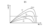
- FIG. 5 shows an output characteristic (PV characteristic) with respect to sunlight intensity.
- the sunlight intensity is higher as the curve A1 is, and the sunlight intensity is lower as the curve A4.
- the output characteristics of the solar panel 11 change depending on the sunlight intensity, the surface temperature, and the like.
- the maximum power point Pmax (the optimum operating voltage Vop) changes in accordance with the sunlight intensity and the like. Therefore, the control circuit 27b performs control to search the maximum power point Pmax by changing the duty ratio of the control signal which follows the input voltage V1 to the optimum operating voltage Vop, that is, turns on and off the transistor T11 of the PV converter 21.
- Control circuit 27 c controls inverter 22 to convert the second DC voltage into an AC voltage. Then, the control circuit 27 a closes the first relay 24 (on) to supply an AC voltage to the first AC load 15 or the commercial power grid 14. Further, the control circuit 27 a supplies the AC voltage to the second AC load 16 with the second relay 25 closed (on).
- FIG. 3 shows an example of the start-up process performed by the control circuit 27a.
- the control circuit 27a executes the processing of steps S1 to S11 shown in FIG. Then, in these processes, the control circuit 27a determines the operation of the first relay 24. As a precondition for starting the start-up process, the DC-DC converters 26b and 26c are not operating, and the first relay 24 is in the open state. Then, in the present embodiment, the control circuit 27a is operated by the operating voltage supplied from the DC-DC converter 26a based on the minute output power output from the solar panel 11. The solar panel 11 starts power generation, for example, when it is irradiated with sunlight by dawn. Since the transistor T11 is off when the PV converter 21 shown in FIG.
- the output voltage V2 appears on the DC voltage bus 28.
- the DC-DC converter 26 a generates a drive voltage of the control circuit 27 a based on the voltage of the DC voltage bus 28. Therefore, by the power generation of the solar panel 11, first, the control circuit 27a operates to perform the start-up process.
- step S1 the control circuit 27a determines whether the input voltage V1 is equal to or higher than the reference voltage.
- the control circuit 27a returns to step S1 if the input voltage V1 is not higher than the reference voltage, and shifts to step S2 if the input voltage V1 is higher than the reference voltage.
- the reference voltage is set to determine whether the solar panel 11 outputs a sufficient voltage, that is, whether the solar panel 11 has a predetermined amount of sunshine or more.
- the open circuit voltage Voc of the solar panel 11 is low when the amount of solar radiation is small, increases with the increase in the amount of solar radiation, and does not change significantly when the amount of solar radiation exceeds a certain level.
- the output voltage of the solar panel 11, that is, the input voltage V1 of the PV converter 21 becomes a value slightly lower than the open circuit voltage Voc by the operation of the DC-DC converter 26a and the control circuit 27a. Accordingly, the control circuit 27a compares the magnitude of the input voltage V1 with the reference voltage to determine whether or not the solar panel 11 has a certain amount of solar radiation (sunlight intensity).
- step S2 the control circuit 27a determines whether the difference between the input voltage V1 and the intermediate voltage (output voltage V2) is equal to or less than a predetermined value.
- the control circuit 27a proceeds to the next step S3 when the difference between the input voltage V1 and the intermediate voltage is equal to or less than a predetermined value, and proceeds to step S1 when the difference is larger than the predetermined value.
- the output voltage V2 passing through the inductor L11 and the diode D11 is a DC voltage bus based on the input voltage V1 of the PV converter 21.
- the intermediate voltage is approximately equal to the input voltage V1.
- the control circuit 27a determines whether the output voltage (input voltage V1) of the solar panel 11 is equal to or higher than the reference voltage in step S1 described above. Therefore, the input voltage V1 and the intermediate voltage (output voltage V2) become equal to or higher than the reference voltage.
- the control circuit 27a can determine the presence or absence of abnormality of the voltage sensors 31, 33 in this step S2.
- the control circuit 27a obtains an input voltage and an input current. Let the input voltage and input current at this time be V1a and I1a, respectively.
- the control circuit 27a starts the operation of the DC-DC converter 26b shown in FIG.
- the control circuit 27a outputs a control signal to the DC-DC converter 26b, and the DC-DC converter 26b starts operation based on the control signal.
- the DC-DC converters 26a and 26b operate. Therefore, the power consumption in the power conditioner 12 is increased compared to when only the DC-DC converter 26a is operating.
- the control circuit 27a obtains an input voltage and an input current. Let the input voltage and input current at this time be V1b and I1b, respectively.
- the control circuit 27a controls the current-voltage of the solar panel 11 based on the input voltage V1a and input current I1a obtained in step S3 described above and the input voltage V1b and input current I1b obtained in step S5. I) Calculate the characteristics and estimate the generated power.
- step S7 the control circuit 27a determines whether the generated power of the solar panel 11 is equal to or more than the drivable power. If the generated power is higher than the drivable power, it is determined that the relays (the first relay 24 and the second relay 25) are closed, and the process proceeds to the next step S8.
- step S8 the control circuit 27a operates the control circuit 27b to start the operation of the PV converter 21.
- step S9 the control circuit 27a operates the control circuit 27c to start the operation of the inverter 22.
- step S10 the control circuit 27a closes the first relay 24 and the second relay 25 (on). Thereafter, the control circuit 27 b controls the PV converter 21 by the MPPT control. Control circuit 27 c controls inverter 22.
- step S7 when the control circuit 27a determines that the generated power is not higher than the drivable power, that is, the generated power is lower than the drivable power, the control circuit 27a proceeds to step S11.
- step S11 the control circuit 27a stops the DC-DC converter 26b and stands by for a predetermined time. Thereafter, the control circuit 27a proceeds to step S1.
- the standby in step S11 prevents repeated execution of the activation determination process in a short time.
- the photovoltaic system 10 includes a solar panel 11 and a power conditioner 12.
- the power conditioner 12 includes a PV converter 21 that generates an output voltage obtained by boosting a DC voltage (input voltage) input from the solar panel 11, an inverter 22 that converts an output voltage of the PV converter 21 into an AC voltage, and an inverter 22 and a first relay 24 connected between the commercial power system 14.
- Control unit 27 includes a control circuit 27 a that controls the entire power conditioner 12, a control circuit 27 b that controls PV converter 21, and a control circuit 27 c that controls inverter 22.
- the DC-DC converter 26 includes DC-DC converters 26a, 26b, 26c that generate drive voltages corresponding to the control circuits 27a, 27b, 27c, respectively.
- the control circuit 27a controls the operation and stop of the DC-DC converter 26b in the start-up process to vary the impedance of the DC-DC converter 26 and the load on the solar panel 11. Then, the control circuit 27a detects the input voltage V1 and the input current I1 of the PV converter 21 and determines whether to close the first relay 24 based on those values.
- the output characteristic (current-voltage (IV) characteristic) of the solar panel 11 is unique to the solar panel 11. Therefore, by detecting the input voltage and the input current of the PV converter 21, that is, the output voltage and the output current of the solar panel 11, the current-voltage (IV) characteristic of the solar panel 11 can be calculated. The generated power of the solar panel 11 can be estimated by this current-voltage (IV) characteristic. If the estimated generated power is greater than or equal to the operable power of the power conditioner 12, the control circuit 27a decides to close the relays (the first relay 24 and the second relay 25). Then, the control circuit 27a is linked to the commercial power grid 14, that is, operates the control circuits 27b and 27c. The activated control circuit 27 b controls the PV converter 21.
- the activated control circuit 27 b controls the inverter 22. Thereby, an alternating voltage is generated based on the generated power of the solar panel 11. Then, the first relay 24 and the second relay 25 can be turned on to supply an AC voltage to the first AC load 15 and the second AC load 16.
- control circuit 27a determines that the relays (the first relay 24 and the second relay 25) are not closed if the estimated generated power of the solar panel 11 is lower than the drivable power, that is, open. Maintain the state. For this reason, the first relay 24 and the second relay 25 are not opened and closed in vain.
- the control circuit 27a stops the DC-DC converter 26b and stands by for a predetermined time (step S11 in FIG. 3). .
- the start-up process is repeatedly performed in a short time, that is, the operation and stop of the DC-DC converter 26b are prevented from being repeated in a short time.
- the sunshine intensity with respect to the solar panel 11 may become strong with time progress like dawn etc.
- the start processing described above in the control circuit 27a suppresses unnecessary switching of the first relay 24 and the second relay 25. it can.
- the control circuit 27a operates the inverter 22 and closes the first relay 24 and the second relay 25.
- the power conditioner 12 can connect the solar panel 11 to the commercial power system 14.
- AC power generated by the power generated by the solar panel 11 can be supplied to the first AC load 15 and the second AC load 16.
- the solar power generation system 10 has a solar panel 11 and a power conditioner 12.
- the power conditioner 12 includes a PV converter 21 that generates an output voltage obtained by boosting a DC voltage (input voltage) input from the solar panel 11, an inverter 22 that converts an output voltage of the PV converter 21 into an AC voltage, and an inverter 22 and a first relay 24 connected between the commercial power system 14.
- Control unit 27 includes a control circuit 27 a that controls the entire power conditioner 12, a control circuit 27 b that controls PV converter 21, and a control circuit 27 c that controls inverter 22.
- the DC-DC converter 26 includes DC-DC converters 26a, 26b, 26c that generate drive voltages corresponding to the control circuits 27a, 27b, 27c, respectively.
- the control circuit 27a controls the operation and stop of the DC-DC converter 26b in the start-up process to vary the impedance of the DC-DC converter 26 and the load on the solar panel 11. Then, the control circuit 27a detects the input voltage V1 and the input current I1 of the PV converter 21 and determines whether to close the first relay 24 based on those values.
- the output characteristics (current-voltage (IV) characteristics) of the solar panel 11 are unique to the solar panel 11.
- the current-voltage (IV) characteristic changes (the output current and output voltage of the solar panel 11) according to the solar radiation intensity to the solar panel 11. Therefore, when a desired output characteristic is obtained, it can be determined whether or not the operation of the entire power conditioner 12 is possible based on the generated power of the solar panel 11 at that time. Therefore, the input voltage and input current of the PV converter 21 when the impedance of the DC-DC converter 26 is varied are detected, and the relays (first relay 24 and second relay 25) are closed according to those values. By determining whether or not to do so, it is possible to suppress unnecessary activation and suppress unnecessary opening and closing of the relays (the first relay 24 and the second relay 25). Therefore, it is possible to suppress the generation of noise and the decrease in mechanical life of the relays (the first relay 24 and the second relay 25).
- the current-voltage (IV) characteristic of the solar panel 11 can be calculated.
- the generated power of the solar panel 11 can be estimated by this current-voltage (IV) characteristic. If the estimated generated power of the solar panel 11 is lower than the operable power, it is determined that the relays (the first relay 24 and the second relay 25) are not closed, that is, the open state is maintained. For this reason, useless starting of the power conditioner 12 can be suppressed, and useless opening and closing of the first relay 24 and the second relay 25 can be suppressed.
- the first embodiment may be implemented in the following manner.
- the solar power generation system 10 a includes a solar panel 11 and a power conditioner 12 a connected to the solar panel 11.
- the power conditioner 12 a is connected to a first AC load 15 corresponding to a self-standing load, assuming use in a so-called off-grid not linked to the power system.
- the first AC load 15 is, for example, an indoor load connected to a distribution board.
- the indoor load includes, for example, lighting equipment, refrigerators, washing machines, air conditioners, microwave ovens, and other household electrical appliances.
- the first AC load 15 described above may be an electrical device in a commercial facility or factory.
- the power conditioner 12 a includes a PV converter 21, an inverter 22, a filter 23, a first relay 24, a DC-DC converter 26, and a control unit 27.
- the PV converter 21, the inverter 22 and the DC-DC converter 26 are connected to one another via a DC voltage bus 28.
- the control unit 27 controls the PV converter 21, the inverter 22, and the first relay 24.
- the PV converter 21 is a step-up chopper circuit that operates according to a control signal from the control unit 27, and boosts and outputs a DC voltage input from the solar panel 11.
- the inverter 22 is a direct current to alternating current conversion circuit operated by a control signal from the control unit 27, and converts the output voltage of the PV converter 21 into an alternating current voltage.
- the filter 23 reduces high frequency components of the AC power output from the inverter 22.
- the DC-DC converter 26 is, for example, a step-down circuit, and converts the DC voltage of the DC voltage bus 28 into a DC voltage suitable for the operation of the control unit 27.
- the control unit 27 operates based on the DC voltage supplied from the DC-DC converter 26, and controls the PV converter 21, the inverter 22, and the first relay 24.
- the first relay 24 is, for example, a normally open electromagnetic relay, and the control unit 27 controls the closed state and the open state according to a control signal.
- the first relay 24 brings the first AC load 15 into and out of contact with the inverter 22.
- the power conditioner 12 a (the control unit 27) enables the self-sustaining operation of operating the first alternating current load 15 with the generated power of the solar panel 11 by the closing operation of the first relay 24.
- the solar power generation system 10 b includes a solar panel 11 and a power conditioner 12 b connected to the solar panel 11.
- the power conditioner 12 a is connected to the commercial power system 14 via the power line 13.
- the commercial power system 14 is a distribution system in which a power company transmits power.
- a first AC load 15 is connected to the power line 13.
- the first AC load 15 is, for example, an indoor load connected to a distribution board in the present embodiment.
- the indoor load includes, for example, lighting equipment, refrigerators, washing machines, air conditioners, microwave ovens, and other household electrical appliances.
- the first AC load 15 described above may be an electrical device in a commercial facility or a factory.
- the power conditioner 12 b converts the DC power generated by the solar panel 11 into AC power and outputs it. Then, the power conditioner 12 b connects or disconnects the solar panel 11 and the commercial power system 14.
- the power conditioner 12 b includes a PV converter 21, an inverter 22, a filter 23, a first relay (simply referred to as “relay”) 24 corresponding to a grid interconnection relay, a DC-DC converter 26, and a control unit 27. ing.
- the PV converter 21, the inverter 22 and the DC-DC converter 26 are connected to one another via a DC voltage bus 28.
- the control unit 27 controls the PV converter 21, the inverter 22, and the first relay 24.
- the PV converter 21 is a step-up chopper circuit that operates according to a control signal from the control unit 27, and boosts and outputs a DC voltage input from the solar panel 11.
- the inverter 22 is a direct current to alternating current conversion circuit operated by a control signal from the control unit 27, and converts the output voltage of the PV converter 21 into an alternating current voltage.
- the filter 23 reduces high frequency components of the AC power output from the inverter 22.
- the DC-DC converter 26 is, for example, a step-down circuit, and converts the DC voltage of the DC voltage bus 28 into a DC voltage suitable for the operation of the control unit 27.
- the control unit 27 operates based on the DC voltage supplied from the DC-DC converter 26, and controls the PV converter 21, the inverter 22, and the first relay 24.
- the first relay 24 is, for example, a normally open electromagnetic relay, and the control unit 27 controls the closed state and the open state according to a control signal.
- the first relay 24 brings the first AC load 15 into and out of contact with the inverter 22.
- the closing operation of the first relay 24 interconnects the solar power generation system 10 b (the solar panel 11) and the commercial power grid 14, and the opening operation of the first relay 24 disconnects the parallel connection.
- Control unit 27 determines whether or not the commercial power system 14 has a power failure.
- the power line 13 is provided with a voltage sensor (not shown), and the control unit 27 determines whether the commercial power system 14 has a power failure based on the detection result of the power sensor.
- the control unit 27 performs an interconnection operation when the commercial power grid 14 does not have a power failure, and opens the first relay 24 when the commercial power grid 14 has a power failure. In this case, if a storage battery or the like other than the PV converter 21 is not connected to the power conditioner 12 b, the power conditioner 12 b stops the operation. When the commercial power grid 14 recovers from the power failure, the control unit 27 closes the first relay 24 to restart the interconnection operation.
- the solar power generation system 110 includes a solar panel 11, a power conditioner 112 connected to the solar panel 11, and a power storage device 113 connected to the power conditioner 112. have.
- Power storage device 113 includes a plurality of storage batteries.
- the power conditioner 112 converts DC power generated by the solar panel 11 into AC power and outputs it. Then, the power conditioner 112 connects or disconnects the solar panel 11 and the commercial power system 14.
- power conditioner 112 charges storage device 113 with DC power generated by solar panel 11. Then, the power conditioner 112 supplies either the generated power of the solar panel 11 or the discharged power of the storage device 113 to the first AC load 15 and the second AC load 16.
- the power conditioner 112 includes a PV converter 21, an inverter 22, a filter 23, a first relay (simply referred to as “relay”) 24 corresponding to a grid interconnection relay, and a second relay (same as a stand-alone grid relay) It has simply a “relay”) 25, a DC-DC converter 126, a control unit 127, and a bidirectional DC-DC converter 29.
- the PV converter 21, the inverter 22 and the DC-DC converter 126 are connected to one another via a DC voltage bus 28.
- the first terminal of bi-directional DC-DC converter 29 is connected to DC voltage bus 28, and the second terminal of bi-directional DC-DC converter 29 is connected to power storage device 113.
- the control unit 127 controls the PV converter 21, the inverter 22, the first relay 24, the second relay 25, and the bidirectional DC-DC converter 29.
- control unit 127 of the present embodiment includes a plurality of (four in the present embodiment) control circuits 27a, 27b, 27c, and 27d.
- the DC-DC converter 126 includes four DC-DC converters 26a, 26b, 26c, 26d corresponding to the control circuits 27a, 27b, 27c, 27d.
- control circuit 27a is a manager circuit that controls the entire power conditioner.
- the control circuit 27 b is a circuit that controls the PV converter 21.
- the control circuit 27 c is a circuit that controls the inverter 22.
- the control circuit 27 d is a circuit that controls the bidirectional DC-DC converter 29.
- the DC-DC converters 26a to 26d are, for example, isolated step-down circuits.
- the DC-DC converter 26a operates at all times, and supplies a drive voltage obtained by stepping down the DC voltage of the DC voltage bus 28 to the control circuit 27a.
- Control of the DC-DC converters 26b to 26d is controlled by the control circuit 27a.
- the operated DC-DC converters 26b to 26d supply the control circuits 27b to 27d with drive voltages obtained by reducing the DC voltage of the DC voltage bus 28.
- the control circuit 27a operates based on the drive voltage supplied from the DC-DC converter 26a, and executes start-up processing described later.
- the control circuit 27a controls activation / stop of the DC-DC converters 26b to 26d. Further, the control circuit 27a controls the operation / stop of the control circuits 27b to 27d.
- the control circuit 27a varies the impedance of the DC-DC converter 126, and detects the output voltage and output current of the solar panel 11, that is, the input voltage V1 and input current I1 of the PV converter 21. Then, the control circuit 27a determines at least the operation of the relay based on the detection result.
- the control circuit 27a changes the impedance of the DC-DC converter 126 by controlling the operation / stop of the DC-DC converter 26b in the start-up process, and the current-voltage (I-V) of the solar panel 11 Measure the characteristics.
- the control circuit 27a estimates the generated power of the solar panel 11 by the current-voltage characteristic.
- the control circuit 27a determines that the operation of the power conditioner 12 is possible when the estimated generated power of the solar panel 11 is greater than the operable power, and the relays (first relay 24, second relay 25) are determined. Decide to close it. Therefore, when sufficient generated power can be obtained by the solar panel 11, alternating current power based on the generated power of the solar panel 11 can be supplied to the first alternating current load 15 and the second alternating current load 16.
- control circuit 27a determines whether or not power can be supplied from power storage device 113. For example, control circuit 27a determines whether or not discharge from power storage device 113 is possible, based on the storage amount (for example, SOC (State of Charge)) of power storage device 113. When it is determined that the discharge is possible, the control circuit 27a operates the control circuit 27d.
- the control circuit 27d controls the bidirectional DC-DC converter 29 to output a desired DC voltage to the DC voltage bus 28 based on the DC voltage discharged from the power storage device 113.
- control circuit 27a operates the control circuit 27c to close the relays (the first relay 24 and the second relay 25).
- the control circuit 27 c controls the inverter 22 and generates an AC voltage based on the DC voltage of the DC voltage bus 28.
- the AC voltage is supplied to the first AC load 15 and the second AC load 16 via the first relay 24 and the second relay 25 in the closed state.
- the power conditioner 112 of the present embodiment has the bidirectional DC-DC converter 29 connected to the power storage device 113.
- the control unit 127 includes a control circuit 27 d that controls the bidirectional DC-DC converter 29.
- the control circuit 27a operates the control circuit 27d to cause the bidirectional DC-DC converter 29 to discharge a DC voltage bus by the discharged power from the storage device 113. Supply DC voltage to 28.
- the control circuit 27a operates the control circuit 27c and causes the inverter 22 to convert the DC voltage of the DC voltage bus 28 into an AC voltage.
- the control circuit 27a can supply an alternating voltage to the first alternating current load 15 and the second alternating current load 16 by closing the relays (the first relay 24 and the second relay 25). And selling from the commercial power system 14 can be suppressed.
- the PV converter 21 and the inverter 22 may be controlled by one control circuit.
- the DC-DC converter 26 includes one DC-DC converter for that one control circuit.
- the control circuit 27a controls the operation / stop of the one DC-DC converter, and estimates the generated power of the solar panel 11.
- the impedance of the DC-DC converter 26 may be varied by controlling the operation / stop of the DC-DC converter 26 c instead of the DC-DC converter 26 b.
- the impedance of the DC-DC converter 26 may be varied by controlling the operation / stop of the two DC-DC converters 26 b and 26 c.
- the load changes.
- the number of DC-DC converters to be controlled corresponds to the amount of load on the solar panel 11 and the power consumption.
- variable load amount By increasing the variable load amount, it is possible to improve the output characteristics (IV characteristic) of the solar panel 11 and the accuracy of the generated power to be estimated. Also in the second embodiment, the accuracy of the generated power to be estimated can be improved by appropriately changing the number of DC-DC converters operated in the start-up process.
- the first corresponding to the power conditioner 112 as a self-supporting load It may be connected to the AC load 15.
- the first relay 24 may be provided and the second relay 25 may not be provided.
- control units 27 and 127 and the control circuits 27a, 27b, 27c, and 27d according to the embodiment are, for example, one or more computer readable instructions configured to realize the operations of the control unit and the control circuit according to the embodiment. And one or more processors configured to execute the computer readable instructions.
- the control unit and control circuit of the embodiment may be an integrated circuit such as an application specific IC (ASIC).
- ASIC application specific IC
Landscapes
- Engineering & Computer Science (AREA)
- Power Engineering (AREA)
- Automation & Control Theory (AREA)
- Electromagnetism (AREA)
- General Physics & Mathematics (AREA)
- Radar, Positioning & Navigation (AREA)
- Physics & Mathematics (AREA)
- Life Sciences & Earth Sciences (AREA)
- Sustainable Development (AREA)
- Sustainable Energy (AREA)
- Inverter Devices (AREA)
- Control Of Electrical Variables (AREA)
- Supply And Distribution Of Alternating Current (AREA)
- Dc-Dc Converters (AREA)
Abstract
パワーコンディショナ12は、太陽光パネル11から入力される直流電圧(入力電圧)を昇圧した出力電圧を生成するPVコンバータ21と、PVコンバータ21の出力電圧を交流電圧に変換するインバータ22と、インバータ22と商用電力系統14との間に接続された第1のリレー24とを有している。制御部27は、パワーコンディショナ12全体を制御する制御回路27aと、PVコンバータ21を制御する制御回路27bと、インバータ22を制御する制御回路27cを含む。制御回路27aは、起動処理において、DC-DCコンバータ26bの作動・停止を制御し、DC-DCコンバータ26のインピーダンスを可変させる。制御回路27aは、PVコンバータ21の入力電圧V1及び入力電流I1を検出し、それらの値に基づいて第1のリレー24を閉状態とするか否かを決定する。
Description
本発明は、太陽光発電システム、パワーコンディショナに関するものである。
従来、太陽光パネルが接続されるパワーコンディショナは、太陽光パネルの直流電力を交流電力に変換するインバータ部と、交流電力を屋内交流負荷に供給する系統連系用リレーとを有している。パワーコンディショナの駆動電力は、商用電力系統から得てもよいが、災害時に自立運転すること等を考えると、太陽光パネルの出力電力から得ることが望ましい。しかしながら、そのようなシステムの場合は、太陽光パネルの出力電力がパワーコンディショナの動作に必要な電力を下回ると停止してしまう。起動したパワーコンディショナは、商用電力系統と連系する際に投入する系統連系用リレーを閉操作(オン)し、交流電力を屋内交流負荷に供給する。パワーコンディショナが停止すると、系統連系用リレーは開動作(オフ)する。
日の出等の時間帯においては、それまでは夜間であるため太陽光パネルの発電はほぼゼロであるので、パワーコンディショナは停止し、系統連系用リレーは開動作(オフ)しているが、日の出と共に太陽光パネルに太陽光が当たり始めると、徐々に発電が始まる。太陽光パネルの開放電圧がある値以上になると、パワーコンディショナは起動を開始するが、この時、太陽光パネルの出力電力が不十分の場合、パワーコンディショナの起動により太陽光パネルの出力電圧がパワーコンディショナの動作に必要な電圧より低下し、パワーコンディショナが停止する。パワーコンディショナが停止すると太陽光パネルの出力電圧が開放電圧まで上昇するため、パワーコンディショナが再び起動する。従って、太陽光パネルの出力電力が不十分の場合、パワーコンディショナは起動と停止を繰り返す。つまり、パワーコンディショナが無駄に起動することとなる。これにより、商用電力系統と連系しないにも関わらず、系統連系用リレーは、閉動作と開動作とを無駄に繰り返すこととなる。このような無駄な開閉動作は、系統連系用リレーにおける騒音の発生や機械的寿命を短くする。
このため、直流電力を交流電力に変換するインバータ部を動作させ、インバータ部の抵抗負荷により電力を消費しているときの直流電圧値により起動判定を行うものが提案されている(例えば、特許文献1参照)。
ところで、上記のように抵抗負荷を用いて起動判定を行う場合、抵抗負荷の抵抗値が小さいと効率の低下をまねくため、抵抗値が大きいことが好ましい。しかし、抵抗値が大きい抵抗負荷を用いると、電力を消費しているときの直流電圧値が小さくなって起動判定が不安定となり、やはり無駄に起動するおそれがある。パワーコンディショナの無駄な起動や停止は、系統連系用リレーの無駄な開閉動作につながり、系統連系用リレーにおける騒音の発生や機械的寿命を短くする。
本発明の目的は、無駄な起動を抑制可能な太陽光発電システム、パワーコンディショナを提供することにある。
本開示の一態様である太陽光発電システムは、太陽光パネルと、前記太陽光パネルに接続されるPVコンバータと、前記PVコンバータから出力される直流電圧を交流電圧に変換するインバータと、前記インバータに、前記交流電圧を供給する第1の交流負荷を接離する第1のリレーと、前記PVコンバータと前記インバータとを制御する制御部と、前記PVコンバータから出力される直流電圧を前記制御部の駆動電圧に変換するDC-DCコンバータと、を有し、前記制御部は、起動処理において、前記DC-DCコンバータのインピーダンスを可変させ、前記PVコンバータの入力電圧と入力電流、または前記PVコンバータの出力電圧と出力電流を検出し、それらの値に応じて少なくとも前記第1のリレーを閉状態とするか否かを決定する。
この構成によれば、DC-DCコンバータのインピーダンスを可変することにより、太陽光パネルに対する負荷、つまり太陽光パネルに対する消費電力が変化する。太陽光パネルの出力特性(電流-電圧(I-V)特性)は、太陽光パネル固有のものである。電流-電圧(I-V)特性は、太陽光パネルに対する日射強度によって変化(太陽光パネルの出力電流、出力電圧が変化)する。従って、所望の出力特性が得られると、そのときの太陽光パネルの発電電力によりパワーコンディショナ全体の動作が可能か否かを判定できる。従って、DC-DCコンバータのインピーダンスを可変したときのPVコンバータの入力電圧と入力電流とを検出し、それらの値により第1のリレーを閉状態とするか否かを決定することで、無駄な起動を抑制し、第1のリレーの無駄な開閉を抑制できる。
上記の太陽光発電システムにおいて、前記第1の交流負荷は電力系統にも接続されていることが好ましい。
この構成によれば、太陽光発電システムを電力系統に系統連系させることで、太陽光パネルの発電量が前記第1の交流負荷が要求する電力を上回ることがあれば、電力系統に逆潮流させることによって余剰電力を無駄にすることがなくなる。
この構成によれば、太陽光発電システムを電力系統に系統連系させることで、太陽光パネルの発電量が前記第1の交流負荷が要求する電力を上回ることがあれば、電力系統に逆潮流させることによって余剰電力を無駄にすることがなくなる。
上記の太陽光発電システムにおいて、前記インバータに、前記交流電圧を供給する第2の交流負荷を接離する第2のリレーを有することが好ましい。
この構成によれば、系統連系用リレーに相当する第1のリレーと、自立運転用リレーに相当する第2のリレーの両方を切り替える構成とすることで、電力系統との連系が停電等で遮断された場合であっても、自立運転を行って第2の交流負荷に対して交流電圧を供給できる。
この構成によれば、系統連系用リレーに相当する第1のリレーと、自立運転用リレーに相当する第2のリレーの両方を切り替える構成とすることで、電力系統との連系が停電等で遮断された場合であっても、自立運転を行って第2の交流負荷に対して交流電圧を供給できる。
上記の太陽光発電システムにおいて、前記制御部は、前記PVコンバータの入力電圧と入力電流、または前記PVコンバータの出力電圧と出力電流から前記太陽光パネルの発電電力を推定し、推定した前記発電電力と運転可能電力とを比較して前記第1のリレー又は前記第2のリレーを閉状態とするか否かを決定することが好ましい。
この構成によれば、PVコンバータの入力電圧と入力電流、つまり太陽光パネルの出力電圧と出力電流を検出することにより、太陽光パネルの電流-電圧(I-V)特性が算出できる。この電流-電圧(I-V)特性により、太陽光パネルの発電電力を推定できる。推定した太陽光パネルの発電電力が運転可能電力より低い場合、第1のリレー又は第2のリレーを閉状態としないことを決定する、つまり開状態を維持する。このため、パワーコンディショナの無駄な起動を抑制し、第1のリレー又は第2のリレーの無駄な開閉を抑制できる。
上記の太陽光発電システムにおいて、前記制御部は、前記起動処理を実行する主制御回路と、前記PVコンバータを制御する第1制御回路と、前記インバータを制御する第2制御回路とを含み、前記DC-DCコンバータは、前記主制御回路の駆動電圧を生成する主変換部と、前記第1制御回路の駆動電圧を生成する第1変換部と、前記第2制御回路の駆動電圧を生成する第2変換部とを含み、前記主制御回路は、前記第1変換部と前記第2変換部の作動・停止を制御するものであり、前記起動処理において少なくとも前記第1変換部の作動・停止を制御して前記DC-DCコンバータのインピーダンスを可変させることが好ましい。
この構成によれば、第1変換部の作動・停止によりDC-DCコンバータのインピーダンスを可変して太陽光パネルの発電電力を判定できる。そして、第1変換部と第2変換部の作動・停止を制御することにより、DC-DCコンバータのインピーダンスの変化量を大きくでき、太陽光パネルの発電電力の推定精度を高くすることが可能となる。
上記の太陽光発電システムにおいて、前記PVコンバータと前記インバータとの間の直流電圧バスに第1端が接続された双方向DC-DCコンバータと、前記双方向DC-DCコンバータの第2端に接続された蓄電装置と、を有することが好ましい。
この構成によれば、太陽光パネルの発電電力がパワーコンディショナの運転可能電力より低い場合、双方向DC-DCコンバータを作動させて蓄電装置からの放電電圧によってインバータを作動させる。そして、インバータにより蓄電装置からの放電電圧を交流電圧に変換することにより、負荷に交流電圧を供給できる。
上記の太陽光発電システムにおいて、前記制御部は、前記太陽光パネルの発電電力が運転可能電力より低い場合、前記PVコンバータを停止し、前記双方向DC-DCコンバータを作動させて前記蓄電装置の蓄積電圧に基づく直流電圧を前記直流電圧バスに出力することが好ましい。
この構成によれば、太陽光パネルの発電電力がパワーコンディショナの運転可能電力より低い場合、双方向DC-DCコンバータを作動させて蓄電装置からの放電電圧によってインバータを作動させる。そして、インバータにより蓄電装置からの放電電圧を交流電圧に変換することにより、負荷に交流電圧を供給できる。
本開示の一態様であるパワーコンディショナは、太陽光パネルから入力される直流電圧を交流電圧に変換して第1の交流負荷に出力するパワーコンディショナであって、前記太陽光パネルに接続されるPVコンバータと、前記PVコンバータから出力される直流電圧を交流電圧に変換するインバータと、前記インバータに前記第1の交流負荷を接離する第1のリレーと、前記PVコンバータと前記インバータとを制御する制御部と、前記PVコンバータから出力される直流電圧を前記制御部の駆動電圧に変換するDC-DCコンバータと、を有し、前記制御部は、起動処理において、前記DC-DCコンバータのインピーダンスを可変させ、前記PVコンバータの入力電圧と入力電流、または前記PVコンバータの出力電圧と出力電流を検出し、それらの値に応じて少なくとも前記第1のリレーを閉状態とするか否かを決定する。
この構成によれば、DC-DCコンバータのインピーダンスを可変することにより、太陽光パネルに対する負荷、つまり太陽光パネルに対する消費電力が変化する。太陽光パネルの出力特性(電流-電圧(I-V)特性)は、太陽光パネル固有のものである。電流-電圧(I-V)特性は、太陽光パネルに対する日射強度によって変化(太陽光パネルの出力電流、出力電圧)が変化する。従って、所望の出力特性が得られると、そのときの太陽光パネルの発電電力によりパワーコンディショナ全体の動作が可能か否かを判定できる。従って、DC-DCコンバータのインピーダンスを可変したときのPVコンバータの入力電圧と入力電流とを検出し、それらの値により第1のリレーを閉状態とするか否かを決定することで、無駄な起動を抑制し、第1のリレーの無駄な開閉を抑制できる。
上記のパワーコンディショナにおいて、前記第1の交流負荷は電力系統にも接続されていることが好ましい。
この構成によれば、電力系統から完全に切り離された状態(オフグリッド)で動作するのではなく、常に電力系統に連系した連系運転とし、停電時にはパワーコンディショナの運転を止める、という動作になる。
この構成によれば、電力系統から完全に切り離された状態(オフグリッド)で動作するのではなく、常に電力系統に連系した連系運転とし、停電時にはパワーコンディショナの運転を止める、という動作になる。
上記のパワーコンディショナにおいて、前記インバータに、前記交流電圧を供給する第2の交流負荷を接離する第2のリレーを有することが好ましい。
この構成によれば、電力系統に問題がない時は系統連系運転とし、停電時には系統連系用リレーに相当する第1のリレーを開成させて系統連系を遮断した上で自立運転をすると共に、第2のリレーを閉成して第2の交流負荷を運転できる。なお、第2の交流負荷は、第2のリレーに接続された自立運転専用コンセントに接続されることが好ましく、この自立運転専用コンセントという別口から自己発電した電力を受け取ることができる。
この構成によれば、電力系統に問題がない時は系統連系運転とし、停電時には系統連系用リレーに相当する第1のリレーを開成させて系統連系を遮断した上で自立運転をすると共に、第2のリレーを閉成して第2の交流負荷を運転できる。なお、第2の交流負荷は、第2のリレーに接続された自立運転専用コンセントに接続されることが好ましく、この自立運転専用コンセントという別口から自己発電した電力を受け取ることができる。
上記のパワーコンディショナは、前記PVコンバータと前記インバータとの間の直流電圧バスに第1端が接続され、第2端に蓄電装置が接続された双方向DC-DCコンバータを有することが好ましい。
この構成によれば、太陽光パネルの発電電力がパワーコンディショナの運転可能電力より低い場合、双方向DC-DCコンバータを作動させて蓄電装置からの放電電圧によってインバータを作動させる。そして、インバータにより蓄電装置からの放電電圧を交流電圧に変換することにより、負荷に交流電圧を供給できる。
本発明の太陽光発電システム、パワーコンディショナによれば、無駄な起動を抑制できる。
(第1実施形態)
以下、第1実施形態を説明する。
図1に示すように、本実施形態の太陽光発電システム10は、太陽光パネル11と、太陽光パネル11に接続されたパワーコンディショナ12とを有している。本実施形態において、パワーコンディショナ12は、電力線13を介して商用電力系統14に接続される。商用電力系統14は、電力会社が電力を伝送する配電系統である。電力線13には、第1の交流負荷15が接続されている。第1の交流負荷15は、例えば分電盤に接続された屋内負荷である。屋内負荷としては、例えば、照明、冷蔵庫、洗濯機、空気調和機、電子レンジ等の一般家屋の電気機器が挙げられる。また、パワーコンディショナ12には、第2の交流負荷16が接続される。第2の交流負荷16は、電気機器のうち、予め選定された負荷であり、照明、等の電気機器が挙げられる。なお、第2の交流負荷16は、パワーコンディショナ12に接続される図示しない自立運転用コンセント(アウトレット)に接続される冷蔵庫、等の電気機器としてもよい。上述の第1の交流負荷15と第2の交流負荷16は、商業施設や工場内の電気機器であってもよい。
以下、第1実施形態を説明する。
図1に示すように、本実施形態の太陽光発電システム10は、太陽光パネル11と、太陽光パネル11に接続されたパワーコンディショナ12とを有している。本実施形態において、パワーコンディショナ12は、電力線13を介して商用電力系統14に接続される。商用電力系統14は、電力会社が電力を伝送する配電系統である。電力線13には、第1の交流負荷15が接続されている。第1の交流負荷15は、例えば分電盤に接続された屋内負荷である。屋内負荷としては、例えば、照明、冷蔵庫、洗濯機、空気調和機、電子レンジ等の一般家屋の電気機器が挙げられる。また、パワーコンディショナ12には、第2の交流負荷16が接続される。第2の交流負荷16は、電気機器のうち、予め選定された負荷であり、照明、等の電気機器が挙げられる。なお、第2の交流負荷16は、パワーコンディショナ12に接続される図示しない自立運転用コンセント(アウトレット)に接続される冷蔵庫、等の電気機器としてもよい。上述の第1の交流負荷15と第2の交流負荷16は、商業施設や工場内の電気機器であってもよい。
パワーコンディショナ12は、太陽光パネル11にて発電した直流電力を交流電力に変換して出力する。そして、パワーコンディショナ12は、太陽光パネル11と商用電力系統14とを連系又は解列する。
パワーコンディショナ12は、PVコンバータ21、インバータ22、フィルタ23、系統連系用リレーに相当する第1のリレー(単に「リレー」と表記)24、自立系統用リレーに相当する第2のリレー(単に「リレー」と表記)25、DC-DCコンバータ26、制御部27を有している。PVコンバータ21とインバータ22とDC-DCコンバータ26は、直流電圧バス28を介して互いに接続されている。制御部27は、PVコンバータ21、インバータ22、第1のリレー24、第2のリレー25を制御する。
PVコンバータ21は、制御部27からの制御信号によって動作する昇圧チョッパ回路であり、太陽光パネル11から入力される直流電圧を昇圧して出力する。インバータ22は、制御部27からの制御信号によって動作する直流交流変換回路であり、PVコンバータ21の出力電圧を交流電圧に変換する。フィルタ23は、インバータ22から出力される交流電力の高周波成分を低減する。
DC-DCコンバータ26は、例えば降圧回路であり、直流電圧バス28の直流電圧を、制御部27の動作に適した直流電圧に変換する。制御部27は、DC-DCコンバータ26から供給される直流電圧に基づいて動作し、PVコンバータ21、インバータ22、第1のリレー24、第2のリレー25を制御する。
第1のリレー24は、例えば常開型の電磁継電器であり、制御部27は制御信号によって閉状態と開状態とを制御する。第1のリレー24は、インバータ22に対して第1の交流負荷15を接離する。第1のリレー24の閉動作により太陽光発電システム10(太陽光パネル11)と商用電力系統14とが連系し、第1のリレー24の開動作により解列する。
第2のリレー25は、例えば常開型の電磁継電器であり、制御部27は制御信号によって閉状態と開状態とを制御する。第2のリレー25は、インバータ22に対して第2の交流負荷16を接離する。パワーコンディショナ12(制御部27)は、第2のリレー25の閉動作により、太陽光パネル11の発電電力により第2の交流負荷16を運転する自立運転を可能とする。なお、自立運転の際、パワーコンディショナ12(制御部27)は、第1のリレー24を開操作(オフ)する。
制御部27は、商用電力系統14が停電しているか否かを判定する。電力線13には図示しない電圧センサが設けられ、制御部27は、その電力センサによる検出結果に基づいて、商用電力系統14が停電しているか否かを判定する。制御部27は、商用電力系統14が停電しているか否かに基づいて連系運転と自立運転とを切り替える切替制御を実行する。制御部27は、商用電力系統14が停電していない場合、連系運転を行い、商用電力系統14が停電した場合、連系運転から自立運転に切り替える。商用電力系統14が停電から復電した場合、制御部27は、自立運転から連系運転に切り替える。制御部27は、連系運転から自立運転に切り替えるとき、パワーコンディショナ12と商用電力系統14とを解列状態とするように第1のリレー24を制御し、かつ第2のリレー25を閉成状態にする。制御部27は、自立運転から連系運転に切り替えるとき、パワーコンディショナ12と商用電力系統14とを連系状態とするように第1のリレー24を制御し、かつ第2のリレー25を開成状態にする。
図2に示すように、太陽光パネル11の正極端子と負極端子はPVコンバータ21に接続されている。PVコンバータ21の出力端子は、直流電圧バス28の高圧側電線28aと低圧側電線28bとに接続されている。
PVコンバータ21は、インダクタL11とトランジスタT11とダイオードD11と平滑コンデンサC11とを有している。インダクタL11の第1端子は太陽光パネル11の正極端子に接続され、インダクタL11の第2端子はトランジスタT11とダイオードD11のアノードに接続されている。ダイオードD11のカソードは、平滑コンデンサC11の第1端子に接続されている。平滑コンデンサC11としては、例えばアルミ電解コンデンサやタンタル電解コンデンサが用いられる。トランジスタT11は、例えばNチャネルMOSFET(Metal-Oxide-Semiconductor Field-Effect Transistor)である。インダクタL11はトランジスタT11のドレイン端子に接続され、トランジスタT11のソース端子は太陽光パネル11の負極端子と、平滑コンデンサC11の第2端子に接続されている。なお、トランジスタT11を絶縁ゲートバイポーラトランジスタ(IGBT:Insulated Gate Bipolar Transistor)等としてもよい。
このPVコンバータ21は、制御信号に応じてトランジスタT11がオンオフすることで、太陽光パネル11から入力する第1の直流電圧を昇圧した第2の直流電圧を、直流電圧バス28に出力する。平滑コンデンサC11は、第2の直流電圧、つまりPVコンバータ21の出力電圧を平滑化する。
インバータ22は、トランジスタT21,T22,T23,T24を含む。トランジスタT21~T24は、例えばNチャネルMOSFETである。なお、トランジスタT21~T24としてIGBT等を用いてもよい。トランジスタT21,T22のドレイン端子は高圧側電線28aに接続され、トランジスタT21,T22のソース端子はトランジスタT23,T24のドレイン端子に接続され、トランジスタT23,T24のソース端子は低圧側電線28bに接続されている。トランジスタT21のソース端子とトランジスタT23のドレイン端子の間の接続点と、トランジスタT22のソース端子とトランジスタT24のドレイン端子の間の接続点は、フィルタ23に接続されている。
フィルタ23は、インダクタL21,L22とコンデンサC21とを含む。フィルタ23は、インバータ22から出力される交流電力の高周波成分を減衰させ、インバータ22の出力電圧と出力電流とを正弦波に近づける。フィルタ23には第1のリレー24と第2のリレー25(図1参照)が接続されている。
パワーコンディショナ12は、電圧センサ31,33と電流センサ32,34とを有している。電圧センサ31は、PVコンバータ21の入力端子間に設けられている。電圧センサ31は、PVコンバータ21の入力電圧を検出するために設けられている。電圧センサ31は、PVコンバータ21の入力電圧に応じた信号を制御部27に出力する。
電流センサ32は、例えば太陽光パネル11の正極端子とPVコンバータ21の間に設けられている。電流センサ32は、PVコンバータ21の入力電流を検出するために設けられている。電流センサ32は、PVコンバータ21の入力電流に応じた信号を制御部27に出力する。
電圧センサ33は、直流電圧バス28に設けられている。電圧センサ33は、直流電圧バス28の高圧側電線28aと低圧側電線28bとの間に接続されている。電圧センサ33は、直流電圧バス28の電圧に応じた信号を制御部27に出力する。
電流センサ34は、例えば直流電圧バス28の高圧側電線28aに設けられている。電流センサ34は、PVコンバータ21の出力電流を検出するために設けられている。電流センサ34は、PVコンバータ21の出力電流に応じた信号を制御部27に出力する。
本実施形態の制御部27は、複数(本実施形態では3つ)の制御回路27a,27b,27cを含む。そして、DC-DCコンバータ26は、制御回路27a,27b,27cに対応する3つのDC-DCコンバータ26a,26b,26cを含む。
本実施形態において、制御回路27aは、パワーコンディショナ全体を制御するマネージャ回路である。制御回路27bは、PVコンバータ21を制御する回路である。そして、制御回路27cは、インバータ22を制御する回路である。
DC-DCコンバータ26a~26cは、例えば絶縁型の降圧回路である。DC-DCコンバータ26aは、常時動作し、直流電圧バス28の直流電圧を降圧した駆動電圧を制御回路27aに供給する。DC-DCコンバータ26b,26cは、制御回路27aにより作動・停止が制御される。作動したDC-DCコンバータ26b,26cは、直流電圧バス28の直流電圧を降圧した駆動電圧を制御回路27b,27cに供給する。
制御回路27aは、DC-DCコンバータ26aから供給される駆動電圧に基づいて動作し、後述する起動処理を実行する。制御回路27aは、DC-DCコンバータ26b,26cの作動・停止を制御する。また、制御回路27aは、制御回路27b,27cの作動・停止を制御する。
例えば、制御回路27aは、DC-DCコンバータ26bを作動・停止を制御するための制御信号を出力する。DC-DCコンバータ26bは、その制御信号に基づいて作動又は停止する。作動したDC-DCコンバータ26bは、直流電圧バス28の直流電圧を降圧した駆動電圧を生成する。その駆動電圧は制御回路27bに供給される。
制御回路27aは、制御回路27bを作動・停止を制御するための制御信号を出力する。制御回路27bは、DC-DCコンバータ26bから供給される駆動電圧に基づいて動作可能となる。そして、制御回路27bは、制御回路27aから入力する制御信号に基づいて動作し、電圧センサ31,33、電流センサ32,34により検出する各値に基づいてPVコンバータ21を制御する。
例えば、制御回路27bは、PVコンバータ21のトランジスタT11をオンオフする制御信号のデューティ比を、例えばパルス幅変調(PWM:Pulse Width Modulation)制御により調整する。そして、制御回路27bは、入力電圧V1と入力電流I1とに基づいて、太陽光パネル11の出力電力を最大にする最大電力点追従(MPPT:Maximum Power Point Tracking)制御を実行する。これにより、PVコンバータ21は、太陽光パネル11から入力する第1の直流電圧を昇圧した第2の直流電圧を生成する。
また、制御回路27aは、DC-DCコンバータ26cを作動・停止を制御するための制御信号を出力する。DC-DCコンバータ26cは、その制御信号に基づいて作動又は停止する。作動したDC-DCコンバータ26cは、直流電圧バス28の直流電圧を降圧した駆動電圧を生成する。その駆動電圧は制御回路27cに供給される。
制御回路27aは、制御回路27cを作動・停止を制御するための制御信号を出力する。制御回路27cは、DC-DCコンバータ26cから供給される駆動電圧に基づいて動作可能となる。そして、制御回路27cは、制御回路27aから入力する制御信号に基づいて動作し、インバータ22のトランジスタT21~T24を制御して第2の直流電圧を交流電圧に変換する。
制御回路27aは、起動処理において、パワーコンディショナ12の運転が可能か否かを判定する。パワーコンディショナ12の運転は、太陽光パネル11の発電電力に基づいて交流電力を生成し、その交流電力を出力することである。つまり、パワーコンディショナ12の運転は、PVコンバータ21の作動と、インバータ22の作動と、第1のリレー24と第2のリレー25とを閉状態とすることを含む。生成した交流電力を出力するためには、リレー(第1のリレー24、第2のリレー25)を閉状態とする必要がある。このため、制御回路27aは、起動処理において、少なくともリレーの作動を決定する。
制御回路27aは、DC-DCコンバータ26のインピーダンスを可変し、太陽光パネル11の出力電圧と出力電流、つまりPVコンバータ21の入力電圧V1と入力電流I1を検出する。そして、制御回路27aは、検出結果に基づいて、少なくともリレーの作動を決定する。
詳述すると、本実施形態において、DC-DCコンバータ26は3つの絶縁型のDC-DCコンバータ26a~26cを含む。DC-DCコンバータ26aは、制御回路27aの駆動電圧を生成するものであり、常時動作する。DC-DCコンバータ26b,26cは、制御回路27aによってその作動と停止が制御される。絶縁型のDC-DCコンバータ26b,26cが停止している場合、直流電圧バス28からDC-DCコンバータ26b,26cに電流は流れない。そして、絶縁型のDC-DCコンバータ26b,26cが作動している場合、直流電圧バス28からDC-DCコンバータ26b,26cに電流が流れる。つまり、日の出が始まる早朝の時間帯になって、それまで待機電力低減のため停止していたDC-DCコンバータ26b,26cを作動させることにより、DC-DCコンバータ26のインピーダンスが変化する。DC-DCコンバータ26のインピーダンスの変化は、PVコンバータ21、つまり太陽光パネル11に対する負荷の変化となる。
本実施形態において、制御回路27aは、DC-DCコンバータ26bの作動・停止を制御する。この場合、1つのDC-DCコンバータ26aが作動しているときと、2つのDC-DCコンバータ26a,26bが動作しているときとで、DC-DCコンバータ26のインピーダンス、つまり太陽光パネル11に対する負荷が変化し、消費電力が変化する。このインピーダンス(負荷)を変化させ、太陽光パネル11の出力電圧と出力電流、つまりPVコンバータ21の入力電圧V1と入力電流I1を検出する。
制御回路27aは、これらの検出結果に基づいて、太陽光パネル11の電流-電圧(I-V)特性を測定する。そして、制御回路27aは、電流-電圧特性により、太陽光パネル11の発電電力を推定する。
図4(a)は、太陽光パネル11の出力電流と出力電圧の特性(I-V特性)を示し、図4(b)は、太陽光パネル11の出力電力と出力電圧の特性(P-V特性)を示す。太陽光パネル11は、日照によって発電し始める。太陽光パネル11は、出力電圧の広い範囲においてほぼ一定の出力電流となる定電流特性を有している。図4(a)において、出力電流が流れない(=0)のときの電圧は開放電圧Vocである。図4(b)において、出力電力が最大となる点を最大電力点Pmaxとし、その時の出力電圧を最適動作電圧Vopとする。太陽光パネル11は、日照強度や表面温度等により出力特性が変化する。例えば、図4(a)に示す電流-電圧(I-V)特性において、出力電流は、日照強度が強くなると多くなり、日照強度が弱くなると少なくなる。出力電流に応じて出力電力も変化する。
制御回路27aは、太陽光パネル11に対応する特性のデータを記憶している。上述の電流-電圧(I-V)特性、電力-電圧(P-V)特性は、接続される太陽光パネル11固有のものである。従って、制御回路27aには、接続される太陽光パネル11に応じて、特性のデータ、例えば出力電圧と出力電流と発電電力とを関連付けたテーブルデータが予め記憶される。なお、特性のデータとして、例えば所定の関数(演算式)の係数が記憶されても良い。
制御回路27aは、記憶した特性のデータに基づいて、太陽光パネル11の発電電力を推定する。そして、制御回路27aは、推定した発電電力と予め設定した運転可能電力とを比較する。運転可能電力は、パワーコンディショナ12全体を動作させるために必要な電力に応じて設定される。また、運転可能電力は、パワーコンディショナ12の動作に応じた変化分や素子の特性等による消費電力のずれ量等を余裕度(マージン)として含む値に設定される。
制御回路27aは、推定した太陽光パネル11の発電電力が運転可能電力以上の場合、パワーコンディショナ12の運転が可能と判断し、リレー(第1のリレー24、第2のリレー25)を閉状態とすることを決定する。一方、推定した発電電力が運転可能電力未満の場合、制御回路27aは、リレー(第1のリレー24、第2のリレー25)を閉状態としない。
制御回路27bは、太陽光パネル11から最大電力が得られるように、PVコンバータ21を制御して、太陽光パネル11から入力する第1の直流電圧を昇圧した第2の直流電圧を生成する。
詳述すると、制御回路27bは、PVコンバータ21のトランジスタT11に制御信号を出力し、トランジスタT11はその制御信号によりオンオフする。インダクタL11は、トランジスタT11がオンしている期間、太陽光パネル11からの電力に基づくエネルギを蓄積する。そして、インダクタL11は、トランジスタT11がオフしている期間、蓄積したエネルギを放出する。これにより、PVコンバータ21は、入力電圧V1を昇圧して、入力電圧V1より高い電圧値の出力電圧V2を出力する。
入力電圧V1に対する出力電圧V2の比(昇圧比)は、PVコンバータ21のトランジスタT11のオン期間とオフ期間、つまりトランジスタT11に供給する制御信号のデューティ比により変更できる。制御回路27bは、昇圧比、つまりトランジスタT11に供給する制御信号のデューティ比を、例えばパルス幅変調(PWM:Pulse Width Modulation)制御により調整する。そして、制御回路27bは、入力電圧V1と入力電流I1とに基づいて、太陽光パネル11の出力電力を最大にする最大電力点追従(MPPT:Maximum Power Point Tracking)制御を実行する。
図5は、日照強度に対する出力特性(P-V特性)を示す。図5において、曲線A1~A4において、曲線A1ほど日照強度が高く、曲線A4ほど日照強度が低い。このように、太陽光パネル11は、日照強度や表面温度等により出力特性が変化する。そして、日照強度等に応じて最大電力点Pmax(最適動作電圧Vop)が変化する。このため、制御回路27bは、入力電圧V1を最適動作電圧Vopに追従する、つまりPVコンバータ21のトランジスタT11をオンオフする制御信号のデューティ比を変化させ、最大電力点Pmaxを探索する制御を行う。
制御回路27cは、インバータ22を制御して第2の直流電圧を交流電圧に変換する。そして、制御回路27aは、第1のリレー24を閉状態(オン)として交流電圧を第1の交流負荷15又は商用電力系統14に供給する。また、制御回路27aは、第2のリレー25を閉状態(オン)として交流電圧を第2の交流負荷16に供給する。
図3は、制御回路27aが実施する起動処理の一例を示す。制御回路27aは、図3に示すステップS1~S11の処理を実行する。そして、これらの処理において、制御回路27aは、第1のリレー24の作動を決定する。起動処理を開始する前提条件として、DC-DCコンバータ26b,26cは動作しておらず、第1のリレー24は開状態である。そして、本実施形態において、制御回路27aには、太陽光パネル11から出力される微少の出力電力に基づいてDC-DCコンバータ26aから供給される動作電圧により動作する。太陽光パネル11は、例えば夜明けによって太陽光が照射されると発電を開始する。図2に示すPVコンバータ21は動作していないときにトランジスタT11がオフであるため、PVコンバータ21の入力電圧V1に応じた出力電圧V2、詳しくは入力電圧V1からインダクタL11とダイオードD11とを通過した出力電圧V2が直流電圧バス28に現れる。DC-DCコンバータ26aは直流電圧バス28の電圧に基づいて制御回路27aの駆動電圧を生成する。従って、太陽光パネル11の発電によって、先ず制御回路27aが動作し、起動処理を実施する。
先ず、ステップS1において、制御回路27aは、入力電圧V1が基準電圧以上か否かを判定する。制御回路27aは、入力電圧V1が基準電圧以上ではない場合にはステップS1に戻り、入力電圧V1が基準電圧以上の場合にはステップS2に移行する。
基準電圧は、太陽光パネル11が十分な電圧を出力しているか否か、つまり太陽光パネル11に対して日照が所定以上あるか否かを判定するために設定される。太陽光パネル11の開放電圧Vocは、日射量が少ないときには低く、日射量の増加によって上昇し、日射量がある程度以上では大きく変化しない。そして、太陽光パネル11の出力電圧、つまりPVコンバータ21の入力電圧V1は、DC-DCコンバータ26aと制御回路27aの動作によって開放電圧Vocから僅かに低下した値となる。従って、制御回路27aは、入力電圧V1と基準電圧とを大小比較することにより、太陽光パネル11に対してある程度の日射量(日照強度)があるか否かを判定する。
次に、ステップS2において、制御回路27aは、入力電圧V1と中間電圧(出力電圧V2)との差が所定値以下か否かを判定する。制御回路27aは入力電圧V1と中間電圧との差が所定値以下の場合に次のステップS3に移行し、差が所定値より大きい場合にはステップS1に移行する。
上述したように、PVコンバータ21は動作していないときにトランジスタT11がオフであるため、PVコンバータ21の入力電圧V1に基づいて、インダクタL11とダイオードD11とを通過した出力電圧V2が直流電圧バス28に現れため、中間電圧は入力電圧V1とほぼ等しい。制御回路27aは、上述のステップS1において、太陽光パネル11の出力電圧(入力電圧V1)が基準電圧以上か否かを判定している。従って、入力電圧V1と中間電圧(出力電圧V2)は基準電圧以上になる。入力電圧V1と中間電圧との差の電圧が所定値以上の場合、入力電圧V1を検出するための電圧センサ31と、中間電圧(出力電圧V2)を検出するための電圧センサ33の少なくとも一方が異常で電圧に応じた信号を出力していない虞がある。従って、制御回路27aは、このステップS2において、電圧センサ31,33の異常の有無を判別することができる。
ステップS3において、制御回路27aは、入力電圧と入力電流とを得る。このときの入力電圧と入力電流をそれぞれV1a,I1aとする。
ステップS4において、制御回路27aは、図2に示すDC-DCコンバータ26bの動作を開始させる。制御回路27aは、DC-DCコンバータ26bに制御信号を出力し、DC-DCコンバータ26bは、その制御信号に基づいて動作を開始する。これにより、パワーコンディショナ12において、DC-DCコンバータ26a,26bが動作する。従って、DC-DCコンバータ26aのみが動作しているときと比べ、パワーコンディショナ12における消費電力が増加する。
ステップS4において、制御回路27aは、図2に示すDC-DCコンバータ26bの動作を開始させる。制御回路27aは、DC-DCコンバータ26bに制御信号を出力し、DC-DCコンバータ26bは、その制御信号に基づいて動作を開始する。これにより、パワーコンディショナ12において、DC-DCコンバータ26a,26bが動作する。従って、DC-DCコンバータ26aのみが動作しているときと比べ、パワーコンディショナ12における消費電力が増加する。
ステップS5において、制御回路27aは、入力電圧と入力電流とを得る。このときの入力電圧と入力電流をそれぞれV1b,I1bとする。
ステップS6において、制御回路27aは、上述のステップS3において得た入力電圧V1a及び入力電流I1aと、ステップS5において得た入力電圧V1b及び入力電流I1bに基づいて、太陽光パネル11の電流-電圧(I-V)特性を算出し、発電電力を推定する。
ステップS6において、制御回路27aは、上述のステップS3において得た入力電圧V1a及び入力電流I1aと、ステップS5において得た入力電圧V1b及び入力電流I1bに基づいて、太陽光パネル11の電流-電圧(I-V)特性を算出し、発電電力を推定する。
ステップS7において、制御回路27aは、太陽光パネル11の発電電力が運転可能電力以上か否かを判定する。発電電力が運転可能電力以上の場合、リレー(第1のリレー24,第2のリレー25)を閉状態とすることを決定し、次のステップS8に移行する。
ステップS8において、制御回路27aは、制御回路27bを作動させ、PVコンバータ21の動作を開始させる。
ステップS9において、制御回路27aは、制御回路27cを作動させ、インバータ22の動作を開始させる。
ステップS9において、制御回路27aは、制御回路27cを作動させ、インバータ22の動作を開始させる。
ステップS10において、制御回路27aは、第1のリレー24及び第2のリレー25を閉状態(オン)とする。この後、制御回路27bは、MPPT制御によりPVコンバータ21を制御する。制御回路27cは、インバータ22を制御する。
上述のステップS7において、制御回路27aは、発電電力が運転可能電力以上ではない、つまり発電電力が運転可能電力より低いと判定した場合、ステップS11に移行する。そのステップS11において、制御回路27aは、DC-DCコンバータ26bを停止し、所定時間待機する。その後、制御回路27aは、ステップS1に移行する。このステップS11における待機により、起動判定処理を短時間で繰り返し実行することを防ぐ。
(作用)
次に、上述の太陽光発電システム10の作用を説明する。
太陽光発電システム10は、太陽光パネル11とパワーコンディショナ12とを有している。パワーコンディショナ12は、太陽光パネル11から入力される直流電圧(入力電圧)を昇圧した出力電圧を生成するPVコンバータ21と、PVコンバータ21の出力電圧を交流電圧に変換するインバータ22と、インバータ22と商用電力系統14との間に接続された第1のリレー24とを有している。制御部27は、パワーコンディショナ12全体を制御する制御回路27aと、PVコンバータ21を制御する制御回路27bと、インバータ22を制御する制御回路27cを含む。DC-DCコンバータ26が、制御回路27a,27b,27cのそれぞれに対応する駆動電圧を生成するDC-DCコンバータ26a,26b,26cを含む。制御回路27aは、起動処理において、DC-DCコンバータ26bの作動・停止を制御し、DC-DCコンバータ26のインピーダンス、太陽光パネル11に対する負荷を可変させる。そして、制御回路27aは、PVコンバータ21の入力電圧V1及び入力電流I1と検出し、それらの値に基づいて第1のリレー24を閉状態とするか否かを決定する。
次に、上述の太陽光発電システム10の作用を説明する。
太陽光発電システム10は、太陽光パネル11とパワーコンディショナ12とを有している。パワーコンディショナ12は、太陽光パネル11から入力される直流電圧(入力電圧)を昇圧した出力電圧を生成するPVコンバータ21と、PVコンバータ21の出力電圧を交流電圧に変換するインバータ22と、インバータ22と商用電力系統14との間に接続された第1のリレー24とを有している。制御部27は、パワーコンディショナ12全体を制御する制御回路27aと、PVコンバータ21を制御する制御回路27bと、インバータ22を制御する制御回路27cを含む。DC-DCコンバータ26が、制御回路27a,27b,27cのそれぞれに対応する駆動電圧を生成するDC-DCコンバータ26a,26b,26cを含む。制御回路27aは、起動処理において、DC-DCコンバータ26bの作動・停止を制御し、DC-DCコンバータ26のインピーダンス、太陽光パネル11に対する負荷を可変させる。そして、制御回路27aは、PVコンバータ21の入力電圧V1及び入力電流I1と検出し、それらの値に基づいて第1のリレー24を閉状態とするか否かを決定する。
例えば、太陽光パネル11の出力特性(電流-電圧(I-V)特性)は、太陽光パネル11固有のものである。従って、PVコンバータ21の入力電圧と入力電流、つまり太陽光パネル11の出力電圧と出力電流を検出することにより、太陽光パネル11の電流-電圧(I-V)特性が算出できる。この電流-電圧(I-V)特性により、太陽光パネル11の発電電力を推定できる。推定した発電電力がパワーコンディショナ12の運転可能電力以上の場合、制御回路27aは、リレー(第1のリレー24、第2のリレー25)を閉状態とすることを決定する。そして、制御回路27aは、商用電力系統14と連系する、つまり制御回路27b,27cを作動させる。作動した制御回路27bはPVコンバータ21を制御する。作動した制御回路27bはインバータ22を制御する。これにより、太陽光パネル11の発電電力に基づいて交流電圧を生成する。そして、第1のリレー24,第2のリレー25をオンして交流電圧を第1の交流負荷15、第2の交流負荷16に供給できる。
一方、制御回路27aは、推定した太陽光パネル11の発電電力が運転可能電力より低い場合、リレー(第1のリレー24、第2のリレー25)を閉状態としないことを決定する、つまり開状態を維持する。このため、第1のリレー24、第2のリレー25は、無駄に開閉しない。
リレー(第1のリレー24、第2のリレー25)を閉状態としないことを決定した場合、制御回路27aは、DC-DCコンバータ26bを停止させ、所定時間待機する(図3のステップS11)。この待機によって、短時間に起動処理が繰り返し実行される、つまりDC-DCコンバータ26bの作動と停止とが短時間に繰り返されることを防止する。
例えば、夜明け等のように、太陽光パネル11に対する日照強度が時間経過とともに強くなる場合がある。この場合、日照強度が弱く、太陽光パネル11の出力電力が運転可能電力より低い場合、制御回路27aにおける上述の起動処理により、第1のリレー24と第2のリレー25の無駄な開閉を抑制できる。そして、太陽が昇って日照強度が強くなり、太陽光パネル11の出力電圧(PVコンバータ21の入力電圧V1)が運転基準値を超えると、太陽光パネル11は、商用電力系統14との連系に十分な電力を発電している。このため、制御回路27aは、インバータ22を動作させるとともに第1のリレー24と第2のリレー25を閉状態とする。これにより、パワーコンディショナ12は、太陽光パネル11を商用電力系統14に連系できる。そして、太陽光パネル11による発電電力により生成した交流電力を、第1の交流負荷15と第2の交流負荷16とに供給できる。
以上記述したように、本実施の形態によれば、以下の効果を奏する。
(1-1)太陽光発電システム10は、太陽光パネル11とパワーコンディショナ12とを有している。パワーコンディショナ12は、太陽光パネル11から入力される直流電圧(入力電圧)を昇圧した出力電圧を生成するPVコンバータ21と、PVコンバータ21の出力電圧を交流電圧に変換するインバータ22と、インバータ22と商用電力系統14との間に接続された第1のリレー24とを有している。制御部27は、パワーコンディショナ12全体を制御する制御回路27aと、PVコンバータ21を制御する制御回路27bと、インバータ22を制御する制御回路27cを含む。DC-DCコンバータ26が、制御回路27a,27b,27cのそれぞれに対応する駆動電圧を生成するDC-DCコンバータ26a,26b,26cを含む。制御回路27aは、起動処理において、DC-DCコンバータ26bの作動・停止を制御し、DC-DCコンバータ26のインピーダンス、太陽光パネル11に対する負荷を可変させる。そして、制御回路27aは、PVコンバータ21の入力電圧V1及び入力電流I1と検出し、それらの値に基づいて第1のリレー24を閉状態とするか否かを決定する。
(1-1)太陽光発電システム10は、太陽光パネル11とパワーコンディショナ12とを有している。パワーコンディショナ12は、太陽光パネル11から入力される直流電圧(入力電圧)を昇圧した出力電圧を生成するPVコンバータ21と、PVコンバータ21の出力電圧を交流電圧に変換するインバータ22と、インバータ22と商用電力系統14との間に接続された第1のリレー24とを有している。制御部27は、パワーコンディショナ12全体を制御する制御回路27aと、PVコンバータ21を制御する制御回路27bと、インバータ22を制御する制御回路27cを含む。DC-DCコンバータ26が、制御回路27a,27b,27cのそれぞれに対応する駆動電圧を生成するDC-DCコンバータ26a,26b,26cを含む。制御回路27aは、起動処理において、DC-DCコンバータ26bの作動・停止を制御し、DC-DCコンバータ26のインピーダンス、太陽光パネル11に対する負荷を可変させる。そして、制御回路27aは、PVコンバータ21の入力電圧V1及び入力電流I1と検出し、それらの値に基づいて第1のリレー24を閉状態とするか否かを決定する。
太陽光パネル11の出力特性(電流-電圧(I-V)特性)は、太陽光パネル11固有のものである。電流-電圧(I-V)特性は、太陽光パネル11に対する日射強度によって変化(太陽光パネル11の出力電流、出力電圧)が変化する。従って、所望の出力特性が得られると、そのときの太陽光パネル11の発電電力によりパワーコンディショナ12全体の動作が可能か否かを判定できる。従って、DC-DCコンバータ26のインピーダンスを可変したときのPVコンバータ21の入力電圧と入力電流とを検出し、それらの値によりリレー(第1のリレー24,第2のリレー25)を閉状態とするか否かを決定することで、無駄な起動を抑制し、リレー(第1のリレー24,第2のリレー25)の無駄な開閉を抑制できる。従って、騒音の発生やリレー(第1のリレー24,第2のリレー25)の機械的寿命の低下を抑制できる。
(1-2)PVコンバータ21の入力電圧と入力電流、つまり太陽光パネル11の出力電圧と出力電流を検出することにより、太陽光パネル11の電流-電圧(I-V)特性が算出できる。この電流-電圧(I-V)特性により、太陽光パネル11の発電電力を推定できる。推定した太陽光パネル11の発電電力が運転可能電力より低い場合、リレー(第1のリレー24、第2のリレー25)を閉状態としないことを決定する、つまり開状態を維持する。このため、パワーコンディショナ12の無駄な起動を抑制し、第1のリレー24、第2のリレー25の無駄な開閉を抑制できる。
尚、上記第1実施形態は、以下の態様で実施してもよい。
(変形例1)
図6に示すように、太陽光発電システム10aは、太陽光パネル11と、太陽光パネル11に接続されたパワーコンディショナ12aとを有している。パワーコンディショナ12aは、電力系統に連系しない、いわゆるオフグリッドでの使用を想定し、自立負荷に相当する第1の交流負荷15に接続されている。第1の交流負荷15は、例えば分電盤に接続された屋内負荷である。屋内負荷としては、例えば、照明、冷蔵庫、洗濯機、空気調和機、電子レンジ等の一般家屋の電気機器が挙げられる。上述の第1の交流負荷15は、商業施設や工場内の電気機器であってもよい。
(変形例1)
図6に示すように、太陽光発電システム10aは、太陽光パネル11と、太陽光パネル11に接続されたパワーコンディショナ12aとを有している。パワーコンディショナ12aは、電力系統に連系しない、いわゆるオフグリッドでの使用を想定し、自立負荷に相当する第1の交流負荷15に接続されている。第1の交流負荷15は、例えば分電盤に接続された屋内負荷である。屋内負荷としては、例えば、照明、冷蔵庫、洗濯機、空気調和機、電子レンジ等の一般家屋の電気機器が挙げられる。上述の第1の交流負荷15は、商業施設や工場内の電気機器であってもよい。
パワーコンディショナ12aは、PVコンバータ21、インバータ22、フィルタ23、第1のリレー24、DC-DCコンバータ26、制御部27を有している。PVコンバータ21とインバータ22とDC-DCコンバータ26は、直流電圧バス28を介して互いに接続されている。制御部27は、PVコンバータ21、インバータ22、第1のリレー24を制御する。
PVコンバータ21は、制御部27からの制御信号によって動作する昇圧チョッパ回路であり、太陽光パネル11から入力される直流電圧を昇圧して出力する。インバータ22は、制御部27からの制御信号によって動作する直流交流変換回路であり、PVコンバータ21の出力電圧を交流電圧に変換する。フィルタ23は、インバータ22から出力される交流電力の高周波成分を低減する。
DC-DCコンバータ26は、例えば降圧回路であり、直流電圧バス28の直流電圧を、制御部27の動作に適した直流電圧に変換する。制御部27は、DC-DCコンバータ26から供給される直流電圧に基づいて動作し、PVコンバータ21、インバータ22、第1のリレー24を制御する。
第1のリレー24は、例えば常開型の電磁継電器であり、制御部27は制御信号によって閉状態と開状態とを制御する。第1のリレー24は、インバータ22に対して第1の交流負荷15を接離する。パワーコンディショナ12a(制御部27)は、第1のリレー24の閉動作により、太陽光パネル11の発電電力により第1の交流負荷15を運転する自立運転を可能とする。
(変形例2)
図7に示すように、太陽光発電システム10bは、太陽光パネル11と、太陽光パネル11に接続されたパワーコンディショナ12bとを有している。本実施形態において、パワーコンディショナ12aは、電力線13を介して商用電力系統14に接続される。商用電力系統14は、電力会社が電力を伝送する配電系統である。電力線13には、第1の交流負荷15が接続されている。第1の交流負荷15は、本実施例においては、例えば分電盤に接続された屋内負荷である。屋内負荷としては、例えば、照明、冷蔵庫、洗濯機、空気調和機、電子レンジ等の一般家屋の電気機器が挙げられる。なお、上述の第1の交流負荷15は、商業施設や工場内の電気機器であってもよい。
図7に示すように、太陽光発電システム10bは、太陽光パネル11と、太陽光パネル11に接続されたパワーコンディショナ12bとを有している。本実施形態において、パワーコンディショナ12aは、電力線13を介して商用電力系統14に接続される。商用電力系統14は、電力会社が電力を伝送する配電系統である。電力線13には、第1の交流負荷15が接続されている。第1の交流負荷15は、本実施例においては、例えば分電盤に接続された屋内負荷である。屋内負荷としては、例えば、照明、冷蔵庫、洗濯機、空気調和機、電子レンジ等の一般家屋の電気機器が挙げられる。なお、上述の第1の交流負荷15は、商業施設や工場内の電気機器であってもよい。
パワーコンディショナ12bは、太陽光パネル11にて発電した直流電力を交流電力に変換して出力する。そして、パワーコンディショナ12bは、太陽光パネル11と商用電力系統14とを連系又は解列する。
パワーコンディショナ12bは、PVコンバータ21、インバータ22、フィルタ23、系統連系用リレーに相当する第1のリレー(単に「リレー」と表記)24、DC-DCコンバータ26、制御部27を有している。PVコンバータ21とインバータ22とDC-DCコンバータ26は、直流電圧バス28を介して互いに接続されている。制御部27は、PVコンバータ21、インバータ22、第1のリレー24を制御する。
PVコンバータ21は、制御部27からの制御信号によって動作する昇圧チョッパ回路であり、太陽光パネル11から入力される直流電圧を昇圧して出力する。インバータ22は、制御部27からの制御信号によって動作する直流交流変換回路であり、PVコンバータ21の出力電圧を交流電圧に変換する。フィルタ23は、インバータ22から出力される交流電力の高周波成分を低減する。
DC-DCコンバータ26は、例えば降圧回路であり、直流電圧バス28の直流電圧を、制御部27の動作に適した直流電圧に変換する。制御部27は、DC-DCコンバータ26から供給される直流電圧に基づいて動作し、PVコンバータ21、インバータ22、第1のリレー24を制御する。
第1のリレー24は、例えば常開型の電磁継電器であり、制御部27は制御信号によって閉状態と開状態とを制御する。第1のリレー24は、インバータ22に対して第1の交流負荷15を接離する。第1のリレー24の閉動作により太陽光発電システム10b(太陽光パネル11)と商用電力系統14とが連系し、第1のリレー24の開動作により解列する。
制御部27は、商用電力系統14が停電しているか否かを判定する。電力線13には図示しない電圧センサが設けられ、制御部27は、その電力センサによる検出結果に基づいて、商用電力系統14が停電しているか否かを判定する。制御部27は、商用電力系統14が停電していない場合、連系運転を行い、商用電力系統14が停電した場合、第1のリレー24を開成する。この場合、PVコンバータ21以外に蓄電池等がパワーコンディショナ12bに対して接続されていなければ、パワーコンディショナ12bは運転を停止する。商用電力系統14が停電から復電した場合、制御部27は、第1のリレー24を閉成して連系運転を再開する。
(第2実施形態)
以下、第2実施形態を説明する。
なお、この第2実施形態において、上述の第1実施形態と同じ部材については同じ符号を付し、その説明の一部又は全てを省略することがある。
以下、第2実施形態を説明する。
なお、この第2実施形態において、上述の第1実施形態と同じ部材については同じ符号を付し、その説明の一部又は全てを省略することがある。
図8に示すように、本実施形態の太陽光発電システム110は、太陽光パネル11と、太陽光パネル11に接続されたパワーコンディショナ112と、パワーコンディショナ112に接続された蓄電装置113とを有している。蓄電装置113は、複数の蓄電池を含む。
パワーコンディショナ112は、太陽光パネル11にて発電した直流電力を交流電力に変換して出力する。そして、パワーコンディショナ112は、太陽光パネル11と商用電力系統14とを連系又は解列する。
また、パワーコンディショナ112は、太陽光パネル11にて発電した直流電力を蓄電装置113に充電する。そして、パワーコンディショナ112は、太陽光パネル11の発電電力と蓄電装置113の放電電力のいずれか一方を、第1の交流負荷15、第2の交流負荷16に供給する。
パワーコンディショナ112は、PVコンバータ21、インバータ22、フィルタ23、系統連系用リレーに相当する第1のリレー(単に「リレー」と表記)24、自立系統用リレーに相当する第2のリレー(単に「リレー」と表記)25、DC-DCコンバータ126、制御部127、双方向DC-DCコンバータ29を有している。PVコンバータ21とインバータ22とDC-DCコンバータ126は、直流電圧バス28を介して互いに接続されている。双方向DC-DCコンバータ29の第1端子は直流電圧バス28に接続され、双方向DC-DCコンバータ29の第2端子は蓄電装置113に接続されている。制御部127は、PVコンバータ21、インバータ22、第1のリレー24、第2のリレー25、双方向DC-DCコンバータ29を制御する。
図9に示すように、本実施形態の制御部127は、複数(本実施形態では4つ)の制御回路27a,27b,27c,27dを含む。そして、DC-DCコンバータ126は、制御回路27a,27b,27c,27dに対応する4つのDC-DCコンバータ26a,26b,26c,26dを含む。
本実施形態において、制御回路27aは、パワーコンディショナ全体を制御するマネージャ回路である。制御回路27bは、PVコンバータ21を制御する回路である。そして、制御回路27cは、インバータ22を制御する回路である。制御回路27dは、双方向DC-DCコンバータ29を制御する回路である。
DC-DCコンバータ26a~26dは、例えば絶縁型の降圧回路である。DC-DCコンバータ26aは、常時動作し、直流電圧バス28の直流電圧を降圧した駆動電圧を制御回路27aに供給する。DC-DCコンバータ26b~26dは、制御回路27aにより作動・停止が制御される。作動したDC-DCコンバータ26b~26dは、直流電圧バス28の直流電圧を降圧した駆動電圧を制御回路27b~27dに供給する。
制御回路27aは、DC-DCコンバータ26aから供給される駆動電圧に基づいて動作し、後述する起動処理を実行する。制御回路27aは、DC-DCコンバータ26b~26dの作動・停止を制御する。また、制御回路27aは、制御回路27b~27dの作動・停止を制御する。
制御回路27aは、DC-DCコンバータ126のインピーダンスを可変し、太陽光パネル11の出力電圧と出力電流、つまりPVコンバータ21の入力電圧V1と入力電流I1を検出する。そして、制御回路27aは、検出結果に基づいて、少なくともリレーの作動を決定する。
例えば、制御回路27aは、起動処理において、DC-DCコンバータ26bの作動・停止を制御することにより、DC-DCコンバータ126のインピーダンスを可変し、太陽光パネル11の電流-電圧(I-V)特性を測定する。制御回路27aは、電流-電圧特性により、太陽光パネル11の発電電力を推定する。そして、制御回路27aは、推定した太陽光パネル11の発電電力が運転可能電力以上の場合、パワーコンディショナ12の運転が可能と判断し、リレー(第1のリレー24、第2のリレー25)を閉状態とすることを決定する。従って、太陽光パネル11により十分な発電電力が得られる場合、その太陽光パネル11の発電電力に基づく交流電力を、第1の交流負荷15,第2の交流負荷16に供給できる。
一方、推定した発電電力が運転可能電力未満の場合、制御回路27aは、リレー(第1のリレー24)を閉状態としない。この場合、制御回路27aは、制御回路27bを作動させない、つまりPVコンバータ21を作動させない。そして、制御回路27aは、蓄電装置113から電力供給が可能か否かを判定する。例えば、制御回路27aは、蓄電装置113の蓄電量(例えば、SOC(State of Charge))に基づいて、蓄電装置113から放電可能か否かを判定する。放電可能と判定した場合、制御回路27aは、制御回路27dを作動させる。制御回路27dは、双方向DC-DCコンバータ29を制御し、蓄電装置113から放電される直流電圧に基づいて、直流電圧バス28に所望の直流電圧を出力させる。
そして、制御回路27aは、制御回路27cを作動させ、リレー(第1のリレー24,第2のリレー25)を閉状態とする。制御回路27cは、インバータ22を制御し、直流電圧バス28の直流電圧に基づいて交流電圧を生成する。その交流電圧は、閉状態の第1のリレー24,第2のリレー25を介して第1の交流負荷15,第2の交流負荷16に供給される。
以上記述したように、本実施の形態によれば、以下の効果を奏する。
(2-1)上述の第1実施形態と同様の効果が得られる。
(2-2)本実施形態のパワーコンディショナ112は、蓄電装置113に接続された双方向DC-DCコンバータ29を有している。制御部127は、双方向DC-DCコンバータ29を制御する制御回路27dを含む。太陽光パネル11の発電電力(推定値)が運転可能電力より低い場合、制御回路27aは、制御回路27dを作動させ、双方向DC-DCコンバータ29により蓄電装置113からの放電電力により直流電圧バス28に直流電圧を供給する。制御回路27aは、制御回路27cを作動させ、インバータ22により直流電圧バス28の直流電圧を交流電圧に変換する。そして、制御回路27aは、リレー(第1のリレー24,第2のリレー25)を閉状態とすることにより、交流電圧を第1の交流負荷15,第2の交流負荷16に供給できる。そして、商用電力系統14からの売電を抑制できる。
(2-1)上述の第1実施形態と同様の効果が得られる。
(2-2)本実施形態のパワーコンディショナ112は、蓄電装置113に接続された双方向DC-DCコンバータ29を有している。制御部127は、双方向DC-DCコンバータ29を制御する制御回路27dを含む。太陽光パネル11の発電電力(推定値)が運転可能電力より低い場合、制御回路27aは、制御回路27dを作動させ、双方向DC-DCコンバータ29により蓄電装置113からの放電電力により直流電圧バス28に直流電圧を供給する。制御回路27aは、制御回路27cを作動させ、インバータ22により直流電圧バス28の直流電圧を交流電圧に変換する。そして、制御回路27aは、リレー(第1のリレー24,第2のリレー25)を閉状態とすることにより、交流電圧を第1の交流負荷15,第2の交流負荷16に供給できる。そして、商用電力系統14からの売電を抑制できる。
尚、上記各実施形態は、以下の態様で実施してもよい。
・上記第1実施形態に対し、PVコンバータ21とインバータ22とを1つの制御回路により制御するようにしてもよい。その場合、DC-DCコンバータ26は、その1つの制御回路に対する1つのDC-DCコンバータを含む。制御回路27aはその1つのDC-DCコンバータの作動・停止を制御し、太陽光パネル11の発電電力を推定する。
・上記第1実施形態に対し、PVコンバータ21とインバータ22とを1つの制御回路により制御するようにしてもよい。その場合、DC-DCコンバータ26は、その1つの制御回路に対する1つのDC-DCコンバータを含む。制御回路27aはその1つのDC-DCコンバータの作動・停止を制御し、太陽光パネル11の発電電力を推定する。
・上記第1実施形態において、DC-DCコンバータ26bに替えてDC-DCコンバータ26cの作動・停止を制御し、DC-DCコンバータ26のインピーダンスを可変してもよい。また、2つのDC-DCコンバータ26b,26cの作動・停止を制御してDC-DCコンバータ26のインピーダンスを可変してもよい。この場合、1つのDC-DCコンバータ26aが作動しているときと、3つのDC-DCコンバータ26a~26cが動作しているときとで、DC-DCコンバータ26のインピーダンス、つまり太陽光パネル11に対する負荷が変化する。制御するDC-DCコンバータの数は、太陽光パネル11に対する負荷量、消費電力に対応する。可変する負荷量を多くすることにより、太陽光パネル11の出力特性(I-V特性)、推定する発電電力の精度を向上できる。第2実施形態においても同様に、起動処理において作動させるDC-DCコンバータの数を適宜変更することにより、推定する発電電力の精度を向上できる。
・上記第2実施形態において、第1実施形態の変形例1と同様に、電力系統に連系しない、いわゆるオフグリッドでの使用を想定し、パワーコンディショナ112を自立負荷に相当する第1の交流負荷15に接続してもよい。また、上記第2実施形態において、上記第1実施形態の変形例2と同様に、第1のリレー24を有し、第2のリレー25を有していない構成としてもよい。
・実施形態の制御部27、127及び制御回路27a、27b、27c、27dは、例えば、実施形態の制御部及び制御回路の動作を実現するように構成されたコンピュータ可読命令を格納した1つ以上のメモリと、そのコンピュータ可読命令を実行するように構成された1つ以上のプロセッサとを備えてもよい。実施形態の制御部及び制御回路は、特定用途向けIC(ASIC)等の集積回路であってもよい。
11…太陽光パネル、12,112…パワーコンディショナ、14…商用電力系統(電力系統)、15…第1の交流負荷、16…第2の交流負荷、21…PVコンバータ、22…インバータ、24…第1のリレー、25…第2のリレー、26,126…DC-DCコンバータ、26a…DC-DCコンバータ(主変換部)、26b…DC-DCコンバータ(第1変換部)、26c…DC-DCコンバータ(第2変換部)、27,127…制御部、27a…制御回路(主制御回路)、27b…制御回路(第1制御回路)、27c…制御回路(第2制御回路)、28…直流電圧バス、29…双方向DC-DCコンバータ、31,33…電圧センサ、32,34…電流センサ、113…蓄電装置。
Claims (11)
- 太陽光パネルと、
前記太陽光パネルに接続されるPVコンバータと、
前記PVコンバータから出力される直流電圧を交流電圧に変換するインバータと、
前記インバータに、前記交流電圧を供給する第1の交流負荷を接離する第1のリレーと、
前記PVコンバータと前記インバータとを制御する制御部と、
前記PVコンバータから出力される直流電圧を前記制御部の駆動電圧に変換するDC-DCコンバータと、
を有し、
前記制御部は、起動処理において、前記DC-DCコンバータのインピーダンスを可変させ、前記PVコンバータの入力電圧と入力電流、または前記PVコンバータの出力電圧と出力電流を検出し、それらの値に応じて少なくとも前記第1のリレーを閉状態とするか否かを決定する、
太陽光発電システム。 - 前記第1の交流負荷は、電力系統に接続されている、請求項1に記載の太陽光発電システム。
- 前記インバータに、前記交流電圧を供給する第2の交流負荷を接離する第2のリレーを有する、請求項1又は2に記載の太陽光発電システム。
- 前記制御部は、前記PVコンバータの入力電圧と入力電流、または前記PVコンバータの出力電圧と出力電流から前記太陽光パネルの発電電力を推定し、推定した前記発電電力と運転可能電力とを比較して前記第1のリレー又は前記第2のリレーを閉状態とするか否かを決定する、
請求項3に記載の太陽光発電システム。 - 前記制御部は、前記起動処理を実行する主制御回路と、前記PVコンバータを制御する第1制御回路と、前記インバータを制御する第2制御回路とを含み、
前記DC-DCコンバータは、前記主制御回路の駆動電圧を生成する主変換部と、前記第1制御回路の駆動電圧を生成する第1変換部と、前記第2制御回路の駆動電圧を生成する第2変換部とを含み、
前記主制御回路は、前記第1変換部と前記第2変換部の作動・停止を制御するものであり、前記起動処理において少なくとも前記第1変換部の作動・停止を制御して前記DC-DCコンバータのインピーダンスを可変させる、
請求項1~4の何れか1項に記載の太陽光発電システム。 - 前記PVコンバータと前記インバータとの間の直流電圧バスに第1端が接続された双方向DC-DCコンバータと、
前記双方向DC-DCコンバータの第2端に接続された蓄電装置と、
を有する、請求項1~5の何れか1項に記載の太陽光発電システム。 - 前記制御部は、前記太陽光パネルの発電電力が運転可能電力より低い場合、前記PVコンバータを停止し、前記双方向DC-DCコンバータを作動させて前記蓄電装置の蓄積電圧に基づく直流電圧を前記直流電圧バスに出力する、請求項6に記載の太陽光発電システム。
- 太陽光パネルから入力される直流電圧を交流電圧に変換して第1の交流負荷に出力するパワーコンディショナであって、
前記太陽光パネルに接続されるPVコンバータと、
前記PVコンバータから出力される直流電圧を前記交流電圧に変換するインバータと、
前記インバータに前記第1の交流負荷を接離する第1のリレーと、
前記PVコンバータと前記インバータとを制御する制御部と、
前記PVコンバータから出力される直流電圧を前記制御部の駆動電圧に変換するDC-DCコンバータと、
を有し、
前記制御部は、起動処理において、前記DC-DCコンバータのインピーダンスを可変させ、前記PVコンバータの入力電圧と入力電流、または前記PVコンバータの出力電圧と出力電流を検出し、それらの値に応じて少なくとも前記第1のリレーを閉状態とするか否かを決定する、
パワーコンディショナ。 - 前記第1の交流負荷は、電力系統に接続されている、請求項8に記載のパワーコンディショナ。
- 前記インバータに、前記交流電圧を供給する第2の交流負荷を接離する第2のリレーを有する、請求項8又は9に記載のパワーコンディショナ。
- 前記PVコンバータと前記インバータとの間の直流電圧バスに第1端が接続され、第2端に蓄電装置が接続された双方向DC-DCコンバータを有する、
請求項8~10の何れか1項に記載のパワーコンディショナ。
Priority Applications (3)
| Application Number | Priority Date | Filing Date | Title |
|---|---|---|---|
| CN201880054864.8A CN111033432B (zh) | 2017-08-31 | 2018-08-06 | 太阳能发电系统和功率调节器 |
| JP2019539125A JP6849076B2 (ja) | 2017-08-31 | 2018-08-06 | 太陽光発電システム、パワーコンディショナ |
| US16/775,324 US11495966B2 (en) | 2017-08-31 | 2020-01-29 | Solar power generation system and power conditioner |
Applications Claiming Priority (2)
| Application Number | Priority Date | Filing Date | Title |
|---|---|---|---|
| JP2017166748 | 2017-08-31 | ||
| JP2017-166748 | 2017-08-31 |
Related Child Applications (1)
| Application Number | Title | Priority Date | Filing Date |
|---|---|---|---|
| US16/775,324 Continuation US11495966B2 (en) | 2017-08-31 | 2020-01-29 | Solar power generation system and power conditioner |
Publications (1)
| Publication Number | Publication Date |
|---|---|
| WO2019044403A1 true WO2019044403A1 (ja) | 2019-03-07 |
Family
ID=65525334
Family Applications (1)
| Application Number | Title | Priority Date | Filing Date |
|---|---|---|---|
| PCT/JP2018/029444 Ceased WO2019044403A1 (ja) | 2017-08-31 | 2018-08-06 | 太陽光発電システム、パワーコンディショナ |
Country Status (4)
| Country | Link |
|---|---|
| US (1) | US11495966B2 (ja) |
| JP (1) | JP6849076B2 (ja) |
| CN (1) | CN111033432B (ja) |
| WO (1) | WO2019044403A1 (ja) |
Cited By (4)
| Publication number | Priority date | Publication date | Assignee | Title |
|---|---|---|---|---|
| CN114069869A (zh) * | 2021-11-25 | 2022-02-18 | 中北大学 | 一种分布式光伏源网荷储能量流控制方法 |
| JP2023049125A (ja) * | 2021-09-29 | 2023-04-10 | 三菱電機エンジニアリング株式会社 | 電力制御装置及び電力制御方法 |
| JP2023524176A (ja) * | 2021-12-09 | 2023-06-08 | 深▲せん▼市徳蘭明海科技有限公司 | 電力スイッチ回路および電力スイッチ |
| WO2026070312A1 (ja) * | 2024-09-30 | 2026-04-02 | ダイキン工業株式会社 | 制御装置、パワーコンディショナおよびヒートポンプシステム |
Families Citing this family (8)
| Publication number | Priority date | Publication date | Assignee | Title |
|---|---|---|---|---|
| CN109831107B (zh) * | 2019-02-28 | 2021-06-22 | 华为技术有限公司 | 一种功率变换装置以及控制功率变换装置输出阻抗的方法 |
| JP7294101B2 (ja) * | 2019-12-06 | 2023-06-20 | トヨタ自動車株式会社 | 電源装置 |
| WO2022074716A1 (ja) * | 2020-10-05 | 2022-04-14 | 東芝三菱電機産業システム株式会社 | 電力変換装置の制御装置 |
| JP7120474B1 (ja) * | 2020-10-08 | 2022-08-17 | 東芝三菱電機産業システム株式会社 | 電力変換装置 |
| US11522366B1 (en) * | 2021-07-20 | 2022-12-06 | Lunar Energy, Inc. | Photovoltaic disconnect |
| WO2023004712A1 (zh) * | 2021-07-29 | 2023-02-02 | 宁德时代新能源科技股份有限公司 | 充放电装置、电池充电的方法和充放电系统 |
| US20240250545A1 (en) * | 2023-01-23 | 2024-07-25 | Enphase Energy, Inc. | Portable energy system |
| CN115987103B (zh) * | 2023-02-06 | 2023-07-28 | 广东工业大学 | 微型光伏系统多模式升压电路、装置、控制方法和介质 |
Citations (6)
| Publication number | Priority date | Publication date | Assignee | Title |
|---|---|---|---|---|
| JPH09135575A (ja) * | 1995-11-06 | 1997-05-20 | Yaskawa Electric Corp | 太陽光発電用電力変換装置の起動方法 |
| JP2013102631A (ja) * | 2011-11-09 | 2013-05-23 | Panasonic Corp | 太陽光発電用パワーコンディショナ |
| JP2014180182A (ja) * | 2013-03-15 | 2014-09-25 | Omron Corp | パワーコンディショナおよびプログラム |
| JP2015006117A (ja) * | 2013-06-24 | 2015-01-08 | 株式会社ノーリツ | パワーコンディショナ |
| JP2016073204A (ja) * | 2014-09-24 | 2016-05-09 | 田淵電機株式会社 | 系統連系用リレーの異常検出装置、及びパワーコンディショナ |
| WO2017043197A1 (ja) * | 2015-09-09 | 2017-03-16 | 株式会社日立産機システム | パワーコンディショナおよびパワーコンディショナの制御方法 |
Family Cites Families (18)
| Publication number | Priority date | Publication date | Assignee | Title |
|---|---|---|---|---|
| CN101093940A (zh) * | 2006-06-21 | 2007-12-26 | 新疆新能源研究所 | 三相全桥电压型光伏并网装置 |
| JP2009247184A (ja) * | 2008-03-31 | 2009-10-22 | Mitsubishi Electric Corp | 太陽光発電システムおよびその起動方法 |
| US8269372B2 (en) * | 2008-12-23 | 2012-09-18 | Samsung Electro-Mechanics Co., Ltd. | Photovoltaic and fuel cell hybrid generation system using dual converters and single inverter and method of controlling the same |
| JP5723611B2 (ja) | 2011-01-27 | 2015-05-27 | 株式会社日立製作所 | 太陽光発電システム、異常検出方法、及び異常検出システム |
| JP6213163B2 (ja) * | 2013-01-24 | 2017-10-18 | オムロン株式会社 | パワーコンディショナ、太陽電池システム、および異常判定方法 |
| JP6191403B2 (ja) * | 2013-01-24 | 2017-09-06 | オムロン株式会社 | パワーコンディショナ、太陽電池システム、および異常判定方法 |
| JP6064642B2 (ja) * | 2013-02-08 | 2017-01-25 | オムロン株式会社 | 昇圧ユニット、パワーコンディショナ、太陽電池システム、プログラム、および電圧追従方法 |
| JP6082886B2 (ja) * | 2013-02-22 | 2017-02-22 | 株式会社高砂製作所 | 電力調整装置及び電力調整方法 |
| KR20150045719A (ko) * | 2013-10-21 | 2015-04-29 | 서울대학교산학협력단 | 전력변환기가 없는 에너지 공급 회로 및 이를 이용한 전자 장치 |
| JP6109108B2 (ja) * | 2014-03-26 | 2017-04-05 | 大和ハウス工業株式会社 | 電力供給システム |
| FR3029326B1 (fr) | 2014-12-02 | 2018-01-26 | Imeon Energy | Procede et systeme pour la gestion d’energie |
| TWM523229U (zh) * | 2015-12-15 | 2016-06-01 | 國家中山科學研究院 | 叢集式儲能微電網系統 |
| CN106329567B (zh) * | 2016-08-30 | 2018-12-21 | 上海新华控制技术集团科技有限公司 | 一种基于fpga的光伏并网系统及其实现方法 |
| CN106451547B (zh) * | 2016-10-28 | 2019-05-31 | 阳光电源股份有限公司 | 一种最大功率点追踪方法、控制器及光伏储能系统 |
| JP6881002B2 (ja) * | 2017-05-09 | 2021-06-02 | 住友電気工業株式会社 | 電力変換装置および電力変換システム |
| WO2019077958A1 (ja) * | 2017-10-17 | 2019-04-25 | 株式会社村田製作所 | 電源装置、電力制御装置、電源装置のリレー判定方法 |
| AU2019435207B2 (en) * | 2019-03-15 | 2024-12-19 | Ge Grid Solutions Llc | Customizable power converter and customizable power conversion system |
| CN216056456U (zh) * | 2021-08-21 | 2022-03-15 | 广东省华虎新能源科技有限公司 | 智能控制型市电互补发电系统 |
-
2018
- 2018-08-06 WO PCT/JP2018/029444 patent/WO2019044403A1/ja not_active Ceased
- 2018-08-06 JP JP2019539125A patent/JP6849076B2/ja active Active
- 2018-08-06 CN CN201880054864.8A patent/CN111033432B/zh active Active
-
2020
- 2020-01-29 US US16/775,324 patent/US11495966B2/en active Active
Patent Citations (6)
| Publication number | Priority date | Publication date | Assignee | Title |
|---|---|---|---|---|
| JPH09135575A (ja) * | 1995-11-06 | 1997-05-20 | Yaskawa Electric Corp | 太陽光発電用電力変換装置の起動方法 |
| JP2013102631A (ja) * | 2011-11-09 | 2013-05-23 | Panasonic Corp | 太陽光発電用パワーコンディショナ |
| JP2014180182A (ja) * | 2013-03-15 | 2014-09-25 | Omron Corp | パワーコンディショナおよびプログラム |
| JP2015006117A (ja) * | 2013-06-24 | 2015-01-08 | 株式会社ノーリツ | パワーコンディショナ |
| JP2016073204A (ja) * | 2014-09-24 | 2016-05-09 | 田淵電機株式会社 | 系統連系用リレーの異常検出装置、及びパワーコンディショナ |
| WO2017043197A1 (ja) * | 2015-09-09 | 2017-03-16 | 株式会社日立産機システム | パワーコンディショナおよびパワーコンディショナの制御方法 |
Cited By (8)
| Publication number | Priority date | Publication date | Assignee | Title |
|---|---|---|---|---|
| JP2023049125A (ja) * | 2021-09-29 | 2023-04-10 | 三菱電機エンジニアリング株式会社 | 電力制御装置及び電力制御方法 |
| JP7674978B2 (ja) | 2021-09-29 | 2025-05-12 | 三菱電機エンジニアリング株式会社 | 電力制御装置、電力制御方法及び電力生産方法 |
| CN114069869A (zh) * | 2021-11-25 | 2022-02-18 | 中北大学 | 一种分布式光伏源网荷储能量流控制方法 |
| CN114069869B (zh) * | 2021-11-25 | 2023-06-23 | 中北大学 | 一种分布式光伏源网荷储能量流控制方法 |
| JP2023524176A (ja) * | 2021-12-09 | 2023-06-08 | 深▲せん▼市徳蘭明海科技有限公司 | 電力スイッチ回路および電力スイッチ |
| JP7497470B2 (ja) | 2021-12-09 | 2024-06-10 | 深▲せん▼市徳蘭明海科技有限公司 | 電力スイッチ回路および電力スイッチ |
| WO2026070312A1 (ja) * | 2024-09-30 | 2026-04-02 | ダイキン工業株式会社 | 制御装置、パワーコンディショナおよびヒートポンプシステム |
| JP2026062341A (ja) * | 2024-09-30 | 2026-04-09 | ダイキン工業株式会社 | 制御装置、パワーコンディショナおよびヒートポンプシステム |
Also Published As
| Publication number | Publication date |
|---|---|
| CN111033432A (zh) | 2020-04-17 |
| CN111033432B (zh) | 2022-03-04 |
| US20200169217A1 (en) | 2020-05-28 |
| JP6849076B2 (ja) | 2021-03-24 |
| JPWO2019044403A1 (ja) | 2020-05-28 |
| US11495966B2 (en) | 2022-11-08 |
Similar Documents
| Publication | Publication Date | Title |
|---|---|---|
| JP6849076B2 (ja) | 太陽光発電システム、パワーコンディショナ | |
| JP6741169B2 (ja) | 電源装置、電力制御装置、電源装置のリレー判定方法 | |
| CN104713176B (zh) | 光伏空调系统及其控制方法 | |
| JP6566355B2 (ja) | 電力変換装置 | |
| CN114614663A (zh) | 控制方法、光伏逆变器的辅助电源及光伏发电系统 | |
| JP5349687B2 (ja) | 系統連系形インバータ | |
| JPWO2008029711A1 (ja) | 系統連系インバータ装置 | |
| JP6232912B2 (ja) | 太陽光発電用パワーコンディショナ | |
| CN111149275B (zh) | 蓄电装置 | |
| JP4953783B2 (ja) | コンバータ装置および系統連系システム | |
| JP6296878B2 (ja) | 系統連系インバータおよび発電電力推定方法 | |
| CN117767521A (zh) | 一种离网混合供电系统的控制装置、方法和光伏储能空调 | |
| WO2019035320A1 (ja) | 太陽光発電システム、パワーコンディショナ | |
| WO2019065420A1 (ja) | パワーコンディショナ及び太陽光発電システム | |
| JP7491270B2 (ja) | パワーコンディショナ | |
| JP5837454B2 (ja) | 制御装置 | |
| JP7656819B2 (ja) | 昇圧接続回路、電力変換システム | |
| JP7363858B2 (ja) | パワーコンディショナ | |
| JP2015154517A (ja) | Pvパワーコンディショナ | |
| JP6755623B2 (ja) | Pvパワーコンディショナ | |
| CN119030012A (zh) | 逆变器及其控制方法 | |
| JP2016082710A (ja) | 太陽光発電利用システム | |
| JP2022179097A (ja) | 電力変換システム、及び電源装置 |
Legal Events
| Date | Code | Title | Description |
|---|---|---|---|
| 121 | Ep: the epo has been informed by wipo that ep was designated in this application |
Ref document number: 18851124 Country of ref document: EP Kind code of ref document: A1 |
|
| ENP | Entry into the national phase |
Ref document number: 2019539125 Country of ref document: JP Kind code of ref document: A |
|
| NENP | Non-entry into the national phase |
Ref country code: DE |
|
| 122 | Ep: pct application non-entry in european phase |
Ref document number: 18851124 Country of ref document: EP Kind code of ref document: A1 |