WO2019044227A1 - 車両制御装置 - Google Patents
車両制御装置 Download PDFInfo
- Publication number
- WO2019044227A1 WO2019044227A1 PCT/JP2018/026820 JP2018026820W WO2019044227A1 WO 2019044227 A1 WO2019044227 A1 WO 2019044227A1 JP 2018026820 W JP2018026820 W JP 2018026820W WO 2019044227 A1 WO2019044227 A1 WO 2019044227A1
- Authority
- WO
- WIPO (PCT)
- Prior art keywords
- vehicle
- braking force
- control
- control command
- unit
- Prior art date
- Legal status (The legal status is an assumption and is not a legal conclusion. Google has not performed a legal analysis and makes no representation as to the accuracy of the status listed.)
- Ceased
Links
Images

Classifications
-
- B—PERFORMING OPERATIONS; TRANSPORTING
- B60—VEHICLES IN GENERAL
- B60T—VEHICLE BRAKE CONTROL SYSTEMS OR PARTS THEREOF; BRAKE CONTROL SYSTEMS OR PARTS THEREOF, IN GENERAL; ARRANGEMENT OF BRAKING ELEMENTS ON VEHICLES IN GENERAL; PORTABLE DEVICES FOR PREVENTING UNWANTED MOVEMENT OF VEHICLES; VEHICLE MODIFICATIONS TO FACILITATE COOLING OF BRAKES
- B60T8/00—Arrangements for adjusting wheel-braking force to meet varying vehicular or ground-surface conditions, e.g. limiting or varying distribution of braking force
- B60T8/17—Using electrical or electronic regulation means to control braking
- B60T8/1755—Brake regulation specially adapted to control the stability of the vehicle, e.g. taking into account yaw rate or transverse acceleration in a curve
- B60T8/17551—Brake regulation specially adapted to control the stability of the vehicle, e.g. taking into account yaw rate or transverse acceleration in a curve determining control parameters related to vehicle stability used in the regulation, e.g. by calculations involving measured or detected parameters
-
- B—PERFORMING OPERATIONS; TRANSPORTING
- B60—VEHICLES IN GENERAL
- B60T—VEHICLE BRAKE CONTROL SYSTEMS OR PARTS THEREOF; BRAKE CONTROL SYSTEMS OR PARTS THEREOF, IN GENERAL; ARRANGEMENT OF BRAKING ELEMENTS ON VEHICLES IN GENERAL; PORTABLE DEVICES FOR PREVENTING UNWANTED MOVEMENT OF VEHICLES; VEHICLE MODIFICATIONS TO FACILITATE COOLING OF BRAKES
- B60T8/00—Arrangements for adjusting wheel-braking force to meet varying vehicular or ground-surface conditions, e.g. limiting or varying distribution of braking force
- B60T8/17—Using electrical or electronic regulation means to control braking
- B60T8/171—Detecting parameters used in the regulation; Measuring values used in the regulation
-
- B—PERFORMING OPERATIONS; TRANSPORTING
- B60—VEHICLES IN GENERAL
- B60T—VEHICLE BRAKE CONTROL SYSTEMS OR PARTS THEREOF; BRAKE CONTROL SYSTEMS OR PARTS THEREOF, IN GENERAL; ARRANGEMENT OF BRAKING ELEMENTS ON VEHICLES IN GENERAL; PORTABLE DEVICES FOR PREVENTING UNWANTED MOVEMENT OF VEHICLES; VEHICLE MODIFICATIONS TO FACILITATE COOLING OF BRAKES
- B60T8/00—Arrangements for adjusting wheel-braking force to meet varying vehicular or ground-surface conditions, e.g. limiting or varying distribution of braking force
- B60T8/17—Using electrical or electronic regulation means to control braking
- B60T8/1755—Brake regulation specially adapted to control the stability of the vehicle, e.g. taking into account yaw rate or transverse acceleration in a curve
- B60T8/17554—Brake regulation specially adapted to control the stability of the vehicle, e.g. taking into account yaw rate or transverse acceleration in a curve specially adapted for enhancing stability around the vehicles longitudinal axle, i.e. roll-over prevention
-
- B—PERFORMING OPERATIONS; TRANSPORTING
- B60—VEHICLES IN GENERAL
- B60T—VEHICLE BRAKE CONTROL SYSTEMS OR PARTS THEREOF; BRAKE CONTROL SYSTEMS OR PARTS THEREOF, IN GENERAL; ARRANGEMENT OF BRAKING ELEMENTS ON VEHICLES IN GENERAL; PORTABLE DEVICES FOR PREVENTING UNWANTED MOVEMENT OF VEHICLES; VEHICLE MODIFICATIONS TO FACILITATE COOLING OF BRAKES
- B60T8/00—Arrangements for adjusting wheel-braking force to meet varying vehicular or ground-surface conditions, e.g. limiting or varying distribution of braking force
- B60T8/26—Arrangements for adjusting wheel-braking force to meet varying vehicular or ground-surface conditions, e.g. limiting or varying distribution of braking force characterised by producing differential braking between front and rear wheels
-
- B—PERFORMING OPERATIONS; TRANSPORTING
- B60—VEHICLES IN GENERAL
- B60W—CONJOINT CONTROL OF VEHICLE SUB-UNITS OF DIFFERENT TYPE OR DIFFERENT FUNCTION; CONTROL SYSTEMS SPECIALLY ADAPTED FOR HYBRID VEHICLES; ROAD VEHICLE DRIVE CONTROL SYSTEMS FOR PURPOSES NOT RELATED TO THE CONTROL OF A PARTICULAR SUB-UNIT
- B60W30/00—Purposes of road vehicle drive control systems not related to the control of a particular sub-unit, e.g. of systems using conjoint control of vehicle sub-units
- B60W30/02—Control of vehicle driving stability
- B60W30/045—Improving turning performance
-
- G—PHYSICS
- G05—CONTROLLING; REGULATING
- G05D—SYSTEMS FOR CONTROLLING OR REGULATING NON-ELECTRIC VARIABLES
- G05D1/00—Control of position, course, altitude or attitude of land, water, air or space vehicles, e.g. using automatic pilots
- G05D1/08—Control of attitude, i.e. control of roll, pitch, or yaw
- G05D1/0891—Control of attitude, i.e. control of roll, pitch, or yaw specially adapted for land vehicles
-
- B—PERFORMING OPERATIONS; TRANSPORTING
- B60—VEHICLES IN GENERAL
- B60T—VEHICLE BRAKE CONTROL SYSTEMS OR PARTS THEREOF; BRAKE CONTROL SYSTEMS OR PARTS THEREOF, IN GENERAL; ARRANGEMENT OF BRAKING ELEMENTS ON VEHICLES IN GENERAL; PORTABLE DEVICES FOR PREVENTING UNWANTED MOVEMENT OF VEHICLES; VEHICLE MODIFICATIONS TO FACILITATE COOLING OF BRAKES
- B60T2201/00—Particular use of vehicle brake systems; Special systems using also the brakes; Special software modules within the brake system controller
- B60T2201/16—Curve braking control, e.g. turn control within ABS control algorithm
-
- B—PERFORMING OPERATIONS; TRANSPORTING
- B60—VEHICLES IN GENERAL
- B60T—VEHICLE BRAKE CONTROL SYSTEMS OR PARTS THEREOF; BRAKE CONTROL SYSTEMS OR PARTS THEREOF, IN GENERAL; ARRANGEMENT OF BRAKING ELEMENTS ON VEHICLES IN GENERAL; PORTABLE DEVICES FOR PREVENTING UNWANTED MOVEMENT OF VEHICLES; VEHICLE MODIFICATIONS TO FACILITATE COOLING OF BRAKES
- B60T2230/00—Monitoring, detecting special vehicle behaviour; Counteracting thereof
- B60T2230/04—Jerk, soft-stop; Anti-jerk, reduction of pitch or nose-dive when braking
Definitions
- the present invention relates to a vehicle control device that controls the operation of a vehicle.
- a yaw moment (rotational force around the z-axis) may be generated by controlling the braking force on the wheels, thereby promoting or stabilizing the lateral movement of the vehicle.
- Such control is called yaw moment control.
- Patent Document 1 describes yaw moment control.
- the document “provides a motion control device for a vehicle that can improve the maneuverability, stability, and riding comfort.
- control means for independently controlling the driving force of each wheel of the vehicle acceleration / deceleration command calculation means for calculating the acceleration / deceleration command value based on the lateral acceleration, and the first based on Acceleration / deceleration command having first yaw moment command calculation means for calculating a vehicle yaw moment command value, and second yaw moment command calculation means for calculating a second yaw moment command value based on the side slip information;
- the first and second modes that control acceleration / deceleration by generating substantially the same driving force among left and right wheels among the four wheels, and different driving among left and right wheels among the four wheels based on the first yaw moment command value
- the present invention has been made in view of the above problems, and provides a vehicle control device capable of suppressing a sense of discomfort given to a driver when performing yaw moment control.
- the vehicle control device changes the distribution ratio between the braking force for the front wheels and the braking force for the rear wheels according to the output of the computing unit that indicates the yaw moment.
- FIG. 5 is a diagram showing a steering angle, lateral acceleration, lateral jerk, longitudinal acceleration command calculated using Equation 1, and braking force / driving force of four wheels as a time-calendar waveform.
- Decrease of the lateral acceleration is a diagram showing the relationship between the target yaw moment M Z_GVC by the acceleration command value G xc, M + control before and after the G-Vectoring control. It is a figure which illustrates the physical parameter which acts on vehicles, when M + control is carried out.
- FIG. 1 is a block diagram of a vehicle control device 100 according to a first embodiment.
- 5 is a flowchart illustrating an operation of a braking force control unit 130.
- 7 is a flowchart illustrating an operation of a braking force control unit 130 according to the second embodiment.
- the longitudinal acceleration is positive in the forward direction of the vehicle, that is, when the vehicle travels in the forward direction, the longitudinal acceleration that increases the speed is positive.
- the lateral acceleration is positive when the vehicle is turning counterclockwise (counterclockwise) and negative in the reverse direction.
- the turning radius in the counterclockwise direction is positive, and the reciprocal is the running curvature of the vehicle.
- the turning radius counterclockwise is positive, and the reciprocal thereof is the target trajectory curvature.
- the steering angle in the counterclockwise direction is positive.
- G-Vectoring is a method that improves loadability between the front and rear wheels to improve the maneuverability and stability of the vehicle by automatically accelerating and decelerating in conjunction with the lateral movement caused by the steering wheel operation.
- the acceleration / deceleration command value (longitudinal acceleration command value G xc ) is basically a value obtained by multiplying the lateral additive acceleration G y_dot by the gain C xy to give a first-order lag.
- G y vehicle lateral acceleration
- G y_dot vehicle lateral jerk
- C xy gain
- T first-order lag time constant
- s Laplace operator
- G x_DC a deceleration command not linked to lateral motion.
- G x — DC is a deceleration component (offset) which is not linked to the lateral movement, and is a term which is necessary when there is a predictive deceleration when there is a corner ahead or an interval velocity command.
- the sgn (signum) term is a term provided to obtain the above operation for both the right corner and the left corner. Specifically, it is possible to realize an operation of decelerating at the turn-in at the start of steering and stopping the deceleration when steady turning (when lateral acceleration becomes zero) and accelerating at the time of departure from the corner of steering return.
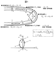
- FIG. 1 is a diagram for explaining a specific traveling example to which G-Vectoring control is applied.
- the traveling track shown in FIG. 1 includes a straight traveling section A, a transient section B, a steady turning section C, a transient section D, and a straight traveling section E.
- the driver does not perform the acceleration / deceleration operation.
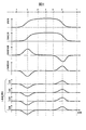
- FIG. 2 is a diagram showing a steering angle, lateral acceleration, lateral jerk, longitudinal acceleration command calculated using Equation 1, and braking force / driving force of four wheels as a time calendar waveform.
- the braking force and the driving force are distributed so that the front outer ring and the front inner ring, and the rear outer ring and the rear inner ring have the same values on the left and right (inner and outer) respectively.
- the braking / driving force is a generic term for the force generated in the vehicle longitudinal direction of each wheel.
- the braking force is a direction force to decelerate the vehicle, and the driving force is defined as a direction force to accelerate the vehicle.
- 1 and FIG. 2 is a lateral acceleration G y generated when the vehicle turns left is positive, longitudinal acceleration G x in front of the vehicle traveling direction as a positive.
- the force generated on each wheel is positive for the driving force and negative for the braking force.
- a vehicle enters a corner from the straight traveling section A.
- the transient period B point 1 to the point 3
- the lateral acceleration G y of the vehicle increases.
- the lateral jerk Gy_dot takes a positive value while the lateral acceleration in the vicinity of the point 2 is increasing (returns to zero at time 3 when the lateral acceleration increase ends).
- a deceleration instruction with an increase of the lateral acceleration G y is generated on the vehicle (G xc is negative).
- braking force (minus sign) of substantially the same magnitude is applied to each of the front, outside, front inside, back outside, and rear inside wheels.
- transient interval D points 5-7
- the lateral acceleration G y of the vehicle decreases by the returning operation of the steering of the driver.
- the lateral additional acceleration Gy_dot of the vehicle is negative, and according to Equation 1, a positive longitudinal acceleration command value Gxc (acceleration command) is generated in the vehicle.
- Gxc acceleration command
- the vehicle decelerates from the turn-in (point 1) at the start of steering to the clipping point (point 3), stops decelerating during steady circular turning (points 3 to 5), and starts steering reverse From point (5) it accelerates at the time of corner exit (point 7).
- G-Vectoring control is applied to the vehicle, the driver can realize acceleration / deceleration movement linked to the lateral movement only by steering for turning.
- a smooth curve (circled It becomes a characteristic movement to transition to).
- the acceleration / deceleration command of the present invention is generated to make a curved transition with the passage of time in this diagram.
- the curved transition for the left corner becomes transition clockwise as shown in FIG. 1, will transition path which was reversed for G x-axis for the right corner, the transition direction is counter clockwise.
- Equation 1 in this control, considering that the first-order lag term and the sign function for the left and right movements are omitted, the value obtained by multiplying the vehicle lateral acceleration by the gain C xy is used as the longitudinal acceleration command. Therefore, by increasing the gain C xy , it is possible to increase the deceleration or acceleration even if the lateral jerk is the same.
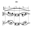
- FIG. 3 is a view showing the relationship between increase / decrease of lateral acceleration, longitudinal acceleration command value G xc of G-Vectoring control, and target yaw moment M z — G VC by M + control.
- the yaw moment around the center of gravity of the vehicle is positive.
- G-Vectoring control In section B where lateral acceleration increases, G-Vectoring control generates a negative longitudinal acceleration command value (that is, decelerates the vehicle), and the yaw force after the start of turning due to the lateral force difference of the vehicle front and rear wheels accompanying load movement. Promote exercise.
- M + control a yaw moment is directly generated around the center of gravity by the braking / driving force difference between the left and right wheels of the vehicle (in FIG. 3, only the left wheel of the vehicle generates a braking force) to promote yaw motion.
- the command value is zero in both G-Vectoring control and M + control.
- G-Vectoring control generates a positive longitudinal acceleration command value (that is, accelerates the vehicle), and the lateral force difference between the vehicle front and rear wheels accompanying load movement causes yaw after the start of turning. Stabilize your movement.
- M + control stabilizes the yawing motion by directly generating a yaw moment around the center of gravity by the braking / driving force difference between the left and right wheels of the vehicle (in FIG. 3, the braking force is generated only at the right wheel of the vehicle).
- both G-Vectoring control and M + control promote yaw motion in a section where the absolute value of lateral acceleration increases, and stabilize yaw motion in a section where the absolute value of lateral acceleration decreases.
- An acceleration command value or a yaw moment command value is generated.
- the suspension included in the vehicle is a mechanism that improves the ride comfort and steering stability by stabilizing the posture of the vehicle.
- a vehicle equipped with front and rear wheel suspension with anti-dive and anti-lift geometry for example, the force that causes the vehicle to move upward on the front wheel if braking is applied while the vehicle is moving forward.
- the force to move the vehicle downward acts, and the attitude of the vehicle can be stabilized by these.
- the M + control Since the M + control generates a yaw moment by applying the braking force of the wheels, the braking force by the M + control acts in addition to the brake operated by the driver. At this time, depending on the distribution ratio of the braking force of the front and rear wheels, the driver may feel discomfort. The reason will be described below.
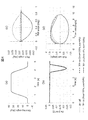
- FIG. 4 is a diagram illustrating physical parameters acting on a vehicle when M + control is performed.
- FIG. 4A shows the change of the steering angle.
- the direction in which the steering wheel is turned counterclockwise is positive.
- Fig.4 (a) after fixing in the state which the driver turned the steering wheel to the left below, the operation
- FIG. 4 (b) shows the deceleration produced by the M + control.
- an example of generating a yaw moment for stabilizing the vehicle when returning the steering wheel is shown. Therefore, in FIG. 4B, when the steering angle returns to the original state, deceleration due to the M + control occurs.
- FIG. 4 (c) shows temporal changes in the pitch angle (rotational angle with the left and right direction of the vehicle as axis) and the roll angle (rotational angle with the longitudinal direction of the vehicle as axis).
- the front and rear wheels of the vehicle have suspensions.
- the direction in which the vehicle leans forward is positive.
- the pitch angle hardly changes with the change of the steering angle.
- M + control it is assumed that the vehicle leans to the front sinking by the braking force. It is considered that even a driver will expect such behavior.
- the broken line is obtained when the distribution ratio of the braking force of the front wheel and the braking force of the rear wheel is 100% for the front wheel and 0% for the rear wheel after the M + control is applied. It can be seen that the braking force causes the vehicle to lean forward.
- the solid line is obtained when the braking force distribution ratio is set to the front wheels 0% and the rear wheels 100% after the M + control is applied. In this case, it can be seen that the front of the vehicle is inclined in the rising direction despite the application of the braking force. Such behavior is considered to give the driver a sense of discomfort.
- the dashed-dotted line is obtained when the braking force distribution ratio is 50% for the front wheels and 50% for the rear wheels after the M + control is applied.
- the braking force is acting, the vehicle hardly leans to the front sink, so it is difficult for the driver to get a sense that the vehicle is decelerating, which may also give a sense of discomfort. .
- FIG. 4 (d) shows temporal changes of the roll rate and the yaw rate (rotational speed about the vertical direction of the vehicle).
- the upper right part of FIG. 4 (d) corresponds to the period in which the M + control is in operation.
- the change in the roll angle tends to be delayed as the distribution of the braking force of the rear wheels increases. If the change in the roll angle is delayed, the driver feels that the vehicle will roll after turning back the steering wheel, which may cause discomfort.
- the driver when the braking force distribution on the rear wheels is large when performing the M + control, the driver does not have a feeling that the vehicle is decelerating and, in addition to the fact that the vehicle rotates after the steering wheel is returned. This gives the driver a sense of discomfort and gives the driver a sense of discomfort. Therefore, in the present invention, when performing the M + control, the braking force distribution of the front wheels is increased.
- FIG. 4 illustrates an example in which the M + control is performed while turning back the steering wheel
- the lateral movement of the vehicle may be promoted by performing the M + control in a period when the turning of the steering wheel starts.
- the same discomfort as shown in FIGS. 4 (c) and 4 (d) is produced to the driver.
- the roll rate is delayed as the rear wheel braking force distribution is increased. Therefore, in this case as well, the braking force of the front wheels may be made larger than the braking force of the rear wheels.
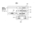
- FIG. 5 is a block diagram of the vehicle control device 100 according to the first embodiment of the present invention.
- the vehicle control device 100 is a device that controls the operation of the vehicle, and is mounted on a vehicle to be controlled.
- the parameter acquisition unit 110, the M + control command calculation unit 120, the braking force control unit 130, and the storage unit 140 are provided.
- the parameter acquisition unit 110 acquires a parameter representing the lateral movement of the vehicle.
- parameters representing the lateral movement of the vehicle include the steering angle, lateral acceleration, yaw rate, and roll rate of the vehicle. These parameters can be obtained, for example, from sensors provided in the vehicle. Alternatively, the parameter acquisition unit 110 may calculate and obtain a parameter that is obtained by calculation.
- the M + control command calculation unit 120 calculates the M + control command value based on the parameters acquired by the parameter acquisition unit 110. For example, as shown in FIGS. 4 (a) and 4 (b), when the steering wheel is turned back, a control command that generates a yaw moment for stabilizing the vehicle is calculated. Alternatively, when the turning of the steering wheel is started, a control command which generates a yaw moment for promoting the lateral movement of the vehicle is calculated.
- the braking force control unit 130 controls the braking force acting on each of the front wheel 210 and the rear wheel 220 by controlling the actuator 200 in accordance with the control command calculated by the M + control command calculating unit 120.
- the braking force control unit 130 otherwise controls the actuator 200 in accordance with, for example, a brake operation by the driver. The detailed operation of the braking force control unit 130 will be described later.
- the storage unit 140 is a storage device that stores data used by the vehicle control device 100. For example, the distribution ratio between the front wheel braking force and the rear wheel braking force can be stored in advance.
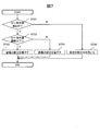
- FIG. 6 is a flowchart for explaining the operation of the braking force control unit 130.
- the braking force control unit 130 repeatedly executes this flowchart, for example, at predetermined intervals. Each step of FIG. 6 will be described below.
- Steps S601 to S602 The braking force control unit 130 acquires a command value of M + control from the M + control command calculation unit 120 (S601). If the M + control is being performed, the process proceeds to step S603. If the M + control is not being performed, the process proceeds to step S604 (S602).
- the braking force control unit 130 reads out from the storage unit 140 the braking force distribution ratio used during execution of the M + control. For example, a distribution ratio in which the braking force distribution of the front wheels is increased more than the braking force distribution of the rear wheels, such as 80% for the front wheels and 20% for the rear wheels, is stored in the storage unit 140 in advance. To determine the braking force of each of the front wheel 210 and the rear wheel 220. Since the optimal braking force distribution during execution of M + control differs depending on the specifications of the vehicle, the optimal value is stored in advance in the storage unit 140 according to the specifications of the vehicle on which the vehicle control device 100 is mounted. Uses its optimum value.
- Step S604 The braking force control unit 130 reads from the storage unit 140 the braking force distribution ratio used when the M + control is not being performed. Similar to step S603, the predetermined distribution ratio is stored in advance in the storage unit 140, and the braking force control unit 130 reads this and determines the braking force of each of the front wheel 210 and the rear wheel 220.
- the vehicle control device 100 makes the braking force distribution of the front wheels more than the braking force distribution of the rear wheels while performing the M + control. Thereby, it is possible to suppress a sense of discomfort given to the driver while performing the M + control. Specifically, it is possible to suppress the pitch angle at which the front of the vehicle floats as described in FIG. 4C and the delay of the roll rate described in FIG. 4D.
- the brake is generally configured such that the braking pressure is actuated by the brake fluid pressure. Since the front wheels require a larger braking force than the rear wheels, even if the propagation of the brake fluid pressure is even between the front wheels and the rear wheels, the braking forces of the front wheels tend to rise more slowly. This may be a hindrance if it is desired to quickly raise the braking force.
- an operation example of switching whether to give priority to raising the braking force in consideration of such characteristics of the brake will be described.
- the configuration of the vehicle control device 100 is the same as that of the first embodiment, and therefore, differences will be mainly described below.
- FIG. 7 is a flowchart for explaining the operation of the braking force control unit 130 in the second embodiment.
- the braking force control unit 130 starts this flowchart after completing the flowchart of FIG. 6, for example. Each step of FIG. 7 will be described below.
- Step S701 The braking force control unit 130 acquires a command value of M + control from the M + control command calculation unit 120. If the absolute value of the control command is increasing (the absolute value of the yaw moment command value is increasing), the process proceeds to step S702. Otherwise, the process proceeds to step S705. When the absolute value of the control command is increasing, this corresponds to a situation where the M + control command calculation unit 120 is about to increase the effect of the M + control.
- Step S702 The braking force control unit 130 determines whether the M + control command value is equal to or less than a threshold.
- the threshold may be stored in advance in the storage unit 140. If the command value is equal to or less than the threshold value, the process proceeds to step S703, and if the threshold value is exceeded, the process proceeds to step S704.
- Step S703 The braking force control unit 130 re-adjusts the braking force distribution ratio determined in step S603 in FIG. 6 to increase the braking force distribution of the rear wheels. For example, in the case where the front wheels are 80% and the rear wheels 20% in step S603, the distribution of the rear wheels is increased such as 50% of the front wheels and 50% of the rear wheels in this step.
- Steps S702 to S703: Supplement 1 When the command value of the M + control is equal to or less than the threshold value, the yaw moment generated by the M + control is small. In this case, since it is considered that the sense of incongruity given to the driver as described in FIG. 4 is small, emphasis is placed on quickly raising the braking force to increase the braking force distribution of the rear wheels where the braking force tends to rise. I decided.
- Step S702 to S703 Supplement 2
- the specific value of the threshold in step S702 differs depending on the characteristics of the vehicle. This is because the rising speed of the braking force of the front and rear wheels and the degree of incongruity given to the driver differ from vehicle to vehicle. Therefore, after determining the optimal threshold according to the characteristics of the vehicle on which the vehicle control device 100 is mounted, the threshold may be stored in the storage unit 140 in advance, and the braking force control unit 130 may read the threshold and use it in step S702. .
- Step S704 The braking force control unit 130 controls the braking force on each of the front wheel 210 and the rear wheel 220 using the distribution ratio of the braking force determined in step S603 in FIG. In this case, the braking force distribution ratio of the front wheel 210 will be larger than that of the rear wheel 220.
- Step S705 The braking force control unit 130 controls the braking force on each of the front wheel 210 and the rear wheel 220 using the previous value of the distribution ratio. Specifically, when the M + control is being performed, the distribution ratio determined in step S603 is used, and in the other cases, the distribution ratio determined in step S604 is used.
- the vehicle control device 100 When the command value of the M + control is small, the vehicle control device 100 according to the second embodiment emphasizes quickly raising the braking force, and increases the braking force distribution of the rear wheels than in step S603. This makes it possible to stabilize the braking force of the vehicle while suppressing the discomfort given to the driver.
- the present invention is not limited to the above embodiment, but includes various modifications.
- the above-described embodiment is described in detail to explain the present invention in an easy-to-understand manner, and is not necessarily limited to one having all the described configurations.
- the parameter acquisition unit 110, the M + control command calculation unit 120, and the braking force control unit 130 can be configured using hardware such as a circuit device on which these functions are implemented. It can also be configured by execution of software having a function implemented by the arithmetic device.
- step S704 the distribution ratio obtained by increasing the distribution of the braking force of the front wheels may be stored in advance in the storage unit 140, and the braking force control unit 130 may read and use the distribution ratio.
- vehicle control device 110 parameter acquisition unit 120: M + control command calculation unit 130: braking force control unit 140: storage unit 200: actuator 210: front wheel 220: rear wheel
Landscapes
- Engineering & Computer Science (AREA)
- Transportation (AREA)
- Mechanical Engineering (AREA)
- Automation & Control Theory (AREA)
- Aviation & Aerospace Engineering (AREA)
- Radar, Positioning & Navigation (AREA)
- Remote Sensing (AREA)
- Physics & Mathematics (AREA)
- General Physics & Mathematics (AREA)
- Regulating Braking Force (AREA)
- Hydraulic Control Valves For Brake Systems (AREA)
- Control Of Driving Devices And Active Controlling Of Vehicle (AREA)
Abstract
Description
以下、本発明に係る車両運動制御装置の実施形態を説明するに先立ち、本発明の理解が容易になるよう、横運動に連係した前後運動制御(G-Vectoring制御)およびヨーモーメント制御(M+制御)の概要と、両者の組み合わせについて説明する。以下の説明においては、車両の重心点を原点とし、車両の前後方向をx、それに直角な方向(車両の横(左右)方向)をyとした場合、x方向の加速度を前後加速度、y方向の加速度を横加速度とする。前後加速度は、車両前方向を正、すなわち車両が前方向に対して進行している際、その速度を増加させる前後加速度を正とする。横加速度は、車両が前方向に対して進行している際、左回り(反時計回り)旋回時に発生する横加速度を正とし、逆方向を負とする。左回りの旋回半径を正とし、その逆数を車両走行曲率とする。同様に、目標軌道に関しても、左回りの旋回半径を正とし、その逆数を目標軌道曲率とする。また、左回り(反時計回り)方向の操舵角を正とする。
G-Vectoringは、ハンドル操作による横運動に連係して自動的に加減速することにより、前輪と後輪の間に荷重移動を発生させて車両の操縦性と安定性の向上を図る方法である。下記式1に示すように、加減速指令値(前後加速度指令値Gxc)は、基本的に横加加速度Gy_dotにゲインCxyを掛け、一次遅れを付与した値とする。式1において、Gy:車両横加速度、Gy_dot:車両横加加速度、Cxy:ゲイン、T:一次遅れ時定数、s:ラプラス演算子、Gx_DC:横運動に連係しない加減速度指令である。G-Vectoringにより、エキスパートドライバの横と前後運動の連係制御ストラテジの一部を模擬することができ、車両の操縦性・安定性の向上が実現できることが確認されている。

M+制御は、上述のG-Vectoring制御の加減速によるヨー運動の促進もしくは安定化と同様の効果を、車両の左右車輪に発生する制駆動力差により与え、ヨー運動の促進もしくは安定性を向上させることを図る方法である。具体的な目標ヨーモーメントMz_GVCは、下記式2により与えられる。Cmnは比例係数、Tmnは一次遅れ時定数である。

4輪を独立して制駆動制御することができる場合、M+制御により発生する前後加速度をG-Vectoring制御の前後加速度指令値と同等とすることにより、両制御が互いに干渉しないようにすることができる。具体的には、左側前後輪に発生する制駆動力の合計値FwLと右側前後輪に発生する制駆動力の合計値FwRとの間の差分により発生するヨーモーメントがM+制御のヨーモーメント指令値となり、FwLとFwRの合計により発生する前後加速度がG-Vectoring制御の前後加速度指令値となるように、それぞれFwLとFwRを決定すればよい。
車両が備えるサスペンションは、車両の姿勢を安定化させることにより乗り心地や操縦安定性を向上させる機構である。アンチダイブジオメトリおよびアンチリフトジオメトリをそれぞれ有する前輪側および後輪側のサスペンションを備える車両においては、例えば車両が前方へ進行しているときブレーキをかけると、前輪側においては車両を上方へ向かわせる力が働き、後輪側においては車両を下方へ向かわせる力が働き、これらによって車両の姿勢を安定化させることができる。
図5は、本発明の実施形態1に係る車両制御装置100の構成図である。車両制御装置100は、車両の動作を制御する装置であり、制御対象である車両に搭載されている。パラメータ取得部110、M+制御指令算出部120、制動力制御部130、記憶部140を備える。
制動力制御部130は、M+制御指令算出部120からM+制御の指令値を取得する(S601)。M+制御を実施中であればステップS603へ進み、実施中でなければステップS604へ進む(S602)。
制動力制御部130は、M+制御を実施中に用いる制動力配分比を記憶部140から読み出す。例えば前輪80%、後輪20%などのように、前輪の制動力配分を後輪の制動力配分よりも多くした配分比をあらかじめ記憶部140に格納しておき、制動力制御部130がこれを読み出して、前輪210と後輪220それぞれの制動力を決定する。M+制御を実施中における最適な制動力配分は車両の仕様によって異なるので、車両制御装置100を搭載する車両の仕様に応じて最適値をあらかじめ記憶部140に格納しておき、制動力制御部130はその最適値を用いる。
制動力制御部130は、M+制御を実施中ではないときに用いる制動力配分比を記憶部140から読み出す。ステップS603と同様に、規定の配分比をあらかじめ記憶部140に格納しておき、制動力制御部130がこれを読み出して、前輪210と後輪220それぞれの制動力を決定する。
本実施形態1に係る車両制御装置100は、M+制御を実施している間は、前輪の制動力配分を後輪の制動力配分よりも多くする。これにより、M+制御を実施中に運転者に対して与える違和感を抑制することができる。具体的には、図4(c)で説明した車両前方が浮き上がるピッチ角や、図4(d)で説明したロールレートの遅れを、抑制することができる。
ブレーキは一般に、ブレーキ液圧によって制動力が作動するように構成されている。前輪のほうが後輪よりも大きな制動力を必要とするので、ブレーキ液圧の伝搬が前輪と後輪との間で均等であったとしても、前輪の制動力のほうが立ち上がりが遅い傾向がある。制動力を速やかに立ち上げたい場合、このことが支障となる可能性がある。本発明の実施形態2では、ブレーキのこのような特性を考慮して、制動力を立ち上げることを優先するか否かを切り替える動作例を説明する。車両制御装置100の構成は実施形態1と同じなので、以下では差異点を中心に説明する。
制動力制御部130は、M+制御指令算出部120からM+制御の指令値を取得する。制御指令の絶対値が増加中である(ヨーモーメントの指令値の絶対値が増加中である)場合はステップS702へ進み、それ以外であればステップS705へ進む。制御指令の絶対値が増加中である場合とは、M+制御指令算出部120がこれからM+制御の作用を増やそうとしている場面がこれに相当する。
制動力制御部130は、M+制御の指令値が閾値以下であるか否かを判定する。閾値は例えばあらかじめ記憶部140に格納しておけばよい。指令値が閾値以下であればステップS703へ進み、閾値を超えていればステップS704へ進む。
制動力制御部130は、図6のステップS603において定めた制動力の配分比を再調整して、後輪の制動力配分を増やす。例えばステップS603において、前輪80%、後輪20%としている場合、本ステップにおいて前輪50%、後輪50%などのように、後輪の配分を増やす。
M+制御の指令値が閾値以下である場合、M+制御により発生させるヨーモーメントは小さいことになる。この場合、図4で説明したような運転者に対して与える違和感は小さいと考えられるので、制動力を速やかに立ち上げることを重視して、制動力が立ち上がり易い後輪の制動力配分を増やすこととした。
ステップS702における閾値の具体的な値は、車両の特性によって異なる。前後輪の制動力の立ち上がり速度や運転手に対して与える違和感の程度は、車両ごとに異なるからである。したがって、車両制御装置100を搭載する車両の特性に応じて最適な閾値を決定した上であらかじめ記憶部140に格納しておき、制動力制御部130はその閾値を読み出してステップS702において用いればよい。
制動力制御部130は、図6のステップS603において定めた制動力の配分比を用いて、前輪210と後輪220それぞれに対する制動力を制御する。この場合は前輪210の制動力配分比を後輪220よりも増やすことになる。
制動力制御部130は、配分比の前回値を用いて、前輪210と後輪220それぞれに対する制動力を制御する。具体的には、M+制御を実施中である場合はステップS603において定めた配分比を用い、それ以外である場合はステップS604において定めた配分比を用いる。
本実施形態2に係る車両制御装置100は、M+制御の指令値が小さい場合は、制動力を速やかに立ち上げることを重視して、後輪の制動力配分をステップS603よりも増やす。これにより、運転者に対して与える違和感を抑制しつつ、車両の制動力を安定化することができる。
本発明は上記実施形態に限定されるものではなく、様々な変形例が含まれる。例えば、上記した実施形態は本発明を分かりやすく説明するために詳細に説明したものであり、必ずしも説明した全ての構成を備えるものに限定されるものではない。
110:パラメータ取得部
120:M+制御指令算出部
130:制動力制御部
140:記憶部
200:アクチュエータ
210:前輪
220:後輪
Claims (8)
- 車両の動作を制御する車両制御装置であって、
車両の横運動を表すパラメータを取得する横運動パラメータ取得部、
前記横運動パラメータ取得部が取得した前記パラメータに基づき前記車両に対して作用するヨーモーメントを指示する演算部、
前記演算部の出力にしたがって前記車両の制動力を制御する制動力制御部、
を備え、
前記制動力制御部は、前記演算部の出力に応じて、前記車両の前輪に対する制動力と前記車両の後輪に対する制動力との間の配分比を変える
ことを特徴とする車両制御装置。 - 前記演算部は、前記ヨーモーメントを指示する制御指令を算出し、
前記制動力制御部は、前記車両が備える前輪に対する制動力と、前記車両が備える後輪に対する制動力とを制御することにより、前記制御指令が指定する前記ヨーモーメントを発生させ、
前記制動力制御部は、前記制御指令にしたがって前記ヨーモーメントを発生させている間は、前記車両の前輪に対する制動力が、前記車両の後輪に対する制動力よりも大きくなるように、前記前輪と前記後輪との間の制動力の配分比を決定する
ことを特徴とする請求項1記載の車両制御装置。 - 前記演算部は、前記車両の横加速度の絶対値がゼロよりも大きい値からゼロへ向かって減少している期間において、前記制御指令として、前記車両の外輪側に制動力を発生させることにより前記車両の横運動を安定化させる、安定化ヨーモーメント指令を算出し、
前記制動力制御部は、前記演算部が前記安定化ヨーモーメント指令を算出している間は、前記車両の前輪に対する制動力が、前記車両の後輪に対する制動力よりも大きくなるように、前記前輪と前記後輪との間の制動力の配分比を決定する
ことを特徴とする請求項2記載の車両制御装置。 - 前記演算部は、前記車両の横加速度の絶対値がゼロから増加している期間において、前記制御指令として、前記車両の内輪側に制動力を発生させることにより前記車両の横運動を促進する、促進ヨーモーメント指令を算出し、
前記制動力制御部は、前記演算部が前記促進ヨーモーメント指令を算出している間は、前記車両の前輪に対する制動力が、前記車両の後輪に対する制動力よりも大きくなるように、前記前輪と前記後輪との間の制動力の配分比を決定する
ことを特徴とする請求項2記載の車両制御装置。 - 前記車両制御装置はさらに、前記制御指令の値と比較するための閾値を格納する記憶部を備え、
前記制動力制御部は、前記演算部が算出した前記制御指令の絶対値が増加中である場合は、前記制御指令の値と前記閾値を比較し、
前記制動力制御部は、前記制御指令の絶対値が増加中でありかつ前記制御指令の絶対値が前記閾値以下である場合は、前記決定した配分比よりも前記後輪の制動力の割合が大きくなるように、前記前輪と前記後輪との間の制動力を再調整する
ことを特徴とする請求項2記載の車両制御装置。 - 前記制動力制御部は、前記制御指令の絶対値が増加中でありかつ前記制御指令の絶対値が前記閾値よりも大きい場合は、前記決定した配分比にしたがって、前記車両の前輪に対する制動力と前記車両の後輪に対する制動力とを決定する
ことを特徴とする請求項5記載の車両制御装置。 - 前記制動力制御部は、前記制御指令の絶対値が増加中でない場合は、前記決定した配分比にしたがって、前記車両の前輪に対する制動力と前記車両の後輪に対する制動力とを決定する
ことを特徴とする請求項5記載の車両制御装置。 - 前記演算部は、前記パラメータの変化にしたがって、前記制御指令を算出する期間と算出しない期間とを切り替え、
前記制動力制御部は、前記配分比を変えた後、前記演算部が前記制御指令を算出しない期間に移行すると、前記配分比を元の値に戻す
ことを特徴とする請求項2記載の車両制御装置。
Priority Applications (3)
| Application Number | Priority Date | Filing Date | Title |
|---|---|---|---|
| US16/638,045 US20200216046A1 (en) | 2017-08-30 | 2018-07-18 | Vehicle control device |
| DE112018003487.9T DE112018003487B4 (de) | 2017-08-30 | 2018-07-18 | Fahrzeugsteuervorrichtung |
| JP2019539043A JP6810274B2 (ja) | 2017-08-30 | 2018-07-18 | 車両制御装置 |
Applications Claiming Priority (2)
| Application Number | Priority Date | Filing Date | Title |
|---|---|---|---|
| JP2017-165560 | 2017-08-30 | ||
| JP2017165560 | 2017-08-30 |
Publications (1)
| Publication Number | Publication Date |
|---|---|
| WO2019044227A1 true WO2019044227A1 (ja) | 2019-03-07 |
Family
ID=65527297
Family Applications (1)
| Application Number | Title | Priority Date | Filing Date |
|---|---|---|---|
| PCT/JP2018/026820 Ceased WO2019044227A1 (ja) | 2017-08-30 | 2018-07-18 | 車両制御装置 |
Country Status (4)
| Country | Link |
|---|---|
| US (1) | US20200216046A1 (ja) |
| JP (1) | JP6810274B2 (ja) |
| DE (1) | DE112018003487B4 (ja) |
| WO (1) | WO2019044227A1 (ja) |
Cited By (1)
| Publication number | Priority date | Publication date | Assignee | Title |
|---|---|---|---|---|
| JP2022524119A (ja) * | 2019-03-12 | 2022-04-27 | ルノー エス.ア.エス. | 自動車両のホイール操舵システムおよび差動ブレーキシステムの組合せ制御のための設定値を生成する方法 |
Families Citing this family (2)
| Publication number | Priority date | Publication date | Assignee | Title |
|---|---|---|---|---|
| JP7846545B2 (ja) * | 2022-03-16 | 2026-04-15 | 株式会社Subaru | 車両の旋回挙動制御装置 |
| DE102022107127A1 (de) | 2022-03-25 | 2023-09-28 | Hyundai Mobis Co., Ltd. | Steuereinrichtung und Steuerverfahren für ein Fahrzeug |
Citations (3)
| Publication number | Priority date | Publication date | Assignee | Title |
|---|---|---|---|---|
| JPH09193776A (ja) * | 1996-01-16 | 1997-07-29 | Toyota Motor Corp | 車輌の挙動制御装置 |
| JP2005202679A (ja) * | 2004-01-15 | 2005-07-28 | Nissan Motor Co Ltd | 車線逸脱防止装置 |
| JP2012035698A (ja) * | 2010-08-05 | 2012-02-23 | Nissan Motor Co Ltd | 車両の制動制御装置 |
Family Cites Families (2)
| Publication number | Priority date | Publication date | Assignee | Title |
|---|---|---|---|---|
| JPH0848256A (ja) * | 1994-08-08 | 1996-02-20 | Toyota Motor Corp | 車両の運動制御装置 |
| JP5970322B2 (ja) * | 2012-10-01 | 2016-08-17 | 日立オートモティブシステムズ株式会社 | 車両の運動制御装置 |
-
2018
- 2018-07-18 DE DE112018003487.9T patent/DE112018003487B4/de active Active
- 2018-07-18 WO PCT/JP2018/026820 patent/WO2019044227A1/ja not_active Ceased
- 2018-07-18 US US16/638,045 patent/US20200216046A1/en not_active Abandoned
- 2018-07-18 JP JP2019539043A patent/JP6810274B2/ja active Active
Patent Citations (3)
| Publication number | Priority date | Publication date | Assignee | Title |
|---|---|---|---|---|
| JPH09193776A (ja) * | 1996-01-16 | 1997-07-29 | Toyota Motor Corp | 車輌の挙動制御装置 |
| JP2005202679A (ja) * | 2004-01-15 | 2005-07-28 | Nissan Motor Co Ltd | 車線逸脱防止装置 |
| JP2012035698A (ja) * | 2010-08-05 | 2012-02-23 | Nissan Motor Co Ltd | 車両の制動制御装置 |
Cited By (2)
| Publication number | Priority date | Publication date | Assignee | Title |
|---|---|---|---|---|
| JP2022524119A (ja) * | 2019-03-12 | 2022-04-27 | ルノー エス.ア.エス. | 自動車両のホイール操舵システムおよび差動ブレーキシステムの組合せ制御のための設定値を生成する方法 |
| JP7492530B2 (ja) | 2019-03-12 | 2024-05-29 | ルノー エス.ア.エス. | 自動車両のホイール操舵システムおよび差動ブレーキシステムの組合せ制御のための設定値を生成する方法 |
Also Published As
| Publication number | Publication date |
|---|---|
| DE112018003487B4 (de) | 2026-01-15 |
| JPWO2019044227A1 (ja) | 2020-04-23 |
| US20200216046A1 (en) | 2020-07-09 |
| JP6810274B2 (ja) | 2021-01-06 |
| DE112018003487T5 (de) | 2020-04-09 |
Similar Documents
| Publication | Publication Date | Title |
|---|---|---|
| JP6764312B2 (ja) | 車両運動制御装置、車両運動制御方法、車両運動制御プログラム | |
| US10843683B2 (en) | Vehicle control device and method | |
| JP6654121B2 (ja) | 車両運動制御装置 | |
| JP6752875B2 (ja) | 走行制御装置 | |
| JP6078124B1 (ja) | 車両の制御装置及び車両の制御方法 | |
| JP6928512B2 (ja) | 運転支援装置、運転支援方法および運転支援システム | |
| WO2013187227A1 (ja) | 車両の走行制御装置 | |
| WO2013180206A1 (ja) | 車両制御装置 | |
| JP2019034591A (ja) | 車両運動制御装置及びその方法、並びに、目標軌道生成装置及びその方法 | |
| JP6449697B2 (ja) | 車両の制御装置及び車両の制御方法 | |
| JP7480856B2 (ja) | 車両運動制御方法及び車両運動制御装置 | |
| US20240001924A1 (en) | Collaborative control of vehicle systems | |
| JP6810274B2 (ja) | 車両制御装置 | |
| WO2022255006A1 (ja) | 車両統合制御装置及び車両統合制御方法 | |
| WO2017026329A1 (ja) | 電動ブレーキシステム | |
| JP2010155561A (ja) | 車両制御装置及び車両制御方法 | |
| JP2017217975A (ja) | スタビライザ制御装置 | |
| WO2019044025A1 (ja) | 移動体の運動制御装置、コンピュータプログラム、移動体の運動制御方法、および制御器 | |
| JP2005218222A (ja) | 車両用挙動制御装置 | |
| JP4923475B2 (ja) | 車両走行制御装置および車両走行制御方法 | |
| JP5369039B2 (ja) | 車両の運動制御装置 | |
| JP2005271823A (ja) | 車両の挙動制御装置 | |
| JP7764901B2 (ja) | 車両制御方法及び車両制御装置 | |
| JP6506811B2 (ja) | 車両の走行制御装置 |
Legal Events
| Date | Code | Title | Description |
|---|---|---|---|
| 121 | Ep: the epo has been informed by wipo that ep was designated in this application |
Ref document number: 18849535 Country of ref document: EP Kind code of ref document: A1 |
|
| ENP | Entry into the national phase |
Ref document number: 2019539043 Country of ref document: JP Kind code of ref document: A |
|
| WWE | Wipo information: entry into national phase |
Ref document number: 112018003487 Country of ref document: DE |
|
| WWP | Wipo information: published in national office |
Ref document number: 112018003487 Country of ref document: DE |
|
| 122 | Ep: pct application non-entry in european phase |
Ref document number: 18849535 Country of ref document: EP Kind code of ref document: A1 |
|
| WWG | Wipo information: grant in national office |
Ref document number: 112018003487 Country of ref document: DE |