WO2019039072A1 - 微粒子数検出器 - Google Patents
微粒子数検出器 Download PDFInfo
- Publication number
- WO2019039072A1 WO2019039072A1 PCT/JP2018/024167 JP2018024167W WO2019039072A1 WO 2019039072 A1 WO2019039072 A1 WO 2019039072A1 JP 2018024167 W JP2018024167 W JP 2018024167W WO 2019039072 A1 WO2019039072 A1 WO 2019039072A1
- Authority
- WO
- WIPO (PCT)
- Prior art keywords
- heater
- gas
- air passage
- particles
- temperature
- Prior art date
- Legal status (The legal status is an assumption and is not a legal conclusion. Google has not performed a legal analysis and makes no representation as to the accuracy of the status listed.)
- Ceased
Links
Images



Classifications
-
- B—PERFORMING OPERATIONS; TRANSPORTING
- B03—SEPARATION OF SOLID MATERIALS USING LIQUIDS OR USING PNEUMATIC TABLES OR JIGS; MAGNETIC OR ELECTROSTATIC SEPARATION OF SOLID MATERIALS FROM SOLID MATERIALS OR FLUIDS; SEPARATION BY HIGH-VOLTAGE ELECTRIC FIELDS
- B03C—MAGNETIC OR ELECTROSTATIC SEPARATION OF SOLID MATERIALS FROM SOLID MATERIALS OR FLUIDS; SEPARATION BY HIGH-VOLTAGE ELECTRIC FIELDS
- B03C3/00—Separating dispersed particles from gases or vapour, e.g. air, by electrostatic effect
- B03C3/01—Pretreatment of the gases prior to electrostatic precipitation
- B03C3/016—Pretreatment of the gases prior to electrostatic precipitation by acoustic or electromagnetic energy, e.g. ultraviolet light
-
- B—PERFORMING OPERATIONS; TRANSPORTING
- B03—SEPARATION OF SOLID MATERIALS USING LIQUIDS OR USING PNEUMATIC TABLES OR JIGS; MAGNETIC OR ELECTROSTATIC SEPARATION OF SOLID MATERIALS FROM SOLID MATERIALS OR FLUIDS; SEPARATION BY HIGH-VOLTAGE ELECTRIC FIELDS
- B03C—MAGNETIC OR ELECTROSTATIC SEPARATION OF SOLID MATERIALS FROM SOLID MATERIALS OR FLUIDS; SEPARATION BY HIGH-VOLTAGE ELECTRIC FIELDS
- B03C3/00—Separating dispersed particles from gases or vapour, e.g. air, by electrostatic effect
- B03C3/017—Combinations of electrostatic separation with other processes, not otherwise provided for
-
- B—PERFORMING OPERATIONS; TRANSPORTING
- B03—SEPARATION OF SOLID MATERIALS USING LIQUIDS OR USING PNEUMATIC TABLES OR JIGS; MAGNETIC OR ELECTROSTATIC SEPARATION OF SOLID MATERIALS FROM SOLID MATERIALS OR FLUIDS; SEPARATION BY HIGH-VOLTAGE ELECTRIC FIELDS
- B03C—MAGNETIC OR ELECTROSTATIC SEPARATION OF SOLID MATERIALS FROM SOLID MATERIALS OR FLUIDS; SEPARATION BY HIGH-VOLTAGE ELECTRIC FIELDS
- B03C3/00—Separating dispersed particles from gases or vapour, e.g. air, by electrostatic effect
- B03C3/02—Plant or installations having external electricity supply
- B03C3/04—Plant or installations having external electricity supply dry type
- B03C3/08—Plant or installations having external electricity supply dry type characterised by presence of stationary flat electrodes arranged with their flat surfaces parallel to the gas stream
-
- B—PERFORMING OPERATIONS; TRANSPORTING
- B03—SEPARATION OF SOLID MATERIALS USING LIQUIDS OR USING PNEUMATIC TABLES OR JIGS; MAGNETIC OR ELECTROSTATIC SEPARATION OF SOLID MATERIALS FROM SOLID MATERIALS OR FLUIDS; SEPARATION BY HIGH-VOLTAGE ELECTRIC FIELDS
- B03C—MAGNETIC OR ELECTROSTATIC SEPARATION OF SOLID MATERIALS FROM SOLID MATERIALS OR FLUIDS; SEPARATION BY HIGH-VOLTAGE ELECTRIC FIELDS
- B03C3/00—Separating dispersed particles from gases or vapour, e.g. air, by electrostatic effect
- B03C3/02—Plant or installations having external electricity supply
- B03C3/04—Plant or installations having external electricity supply dry type
- B03C3/12—Plant or installations having external electricity supply dry type characterised by separation of ionising and collecting stations
-
- B—PERFORMING OPERATIONS; TRANSPORTING
- B03—SEPARATION OF SOLID MATERIALS USING LIQUIDS OR USING PNEUMATIC TABLES OR JIGS; MAGNETIC OR ELECTROSTATIC SEPARATION OF SOLID MATERIALS FROM SOLID MATERIALS OR FLUIDS; SEPARATION BY HIGH-VOLTAGE ELECTRIC FIELDS
- B03C—MAGNETIC OR ELECTROSTATIC SEPARATION OF SOLID MATERIALS FROM SOLID MATERIALS OR FLUIDS; SEPARATION BY HIGH-VOLTAGE ELECTRIC FIELDS
- B03C3/00—Separating dispersed particles from gases or vapour, e.g. air, by electrostatic effect
- B03C3/34—Constructional details or accessories or operation thereof
- B03C3/40—Electrode constructions
- B03C3/41—Ionising-electrodes
-
- B—PERFORMING OPERATIONS; TRANSPORTING
- B03—SEPARATION OF SOLID MATERIALS USING LIQUIDS OR USING PNEUMATIC TABLES OR JIGS; MAGNETIC OR ELECTROSTATIC SEPARATION OF SOLID MATERIALS FROM SOLID MATERIALS OR FLUIDS; SEPARATION BY HIGH-VOLTAGE ELECTRIC FIELDS
- B03C—MAGNETIC OR ELECTROSTATIC SEPARATION OF SOLID MATERIALS FROM SOLID MATERIALS OR FLUIDS; SEPARATION BY HIGH-VOLTAGE ELECTRIC FIELDS
- B03C3/00—Separating dispersed particles from gases or vapour, e.g. air, by electrostatic effect
- B03C3/34—Constructional details or accessories or operation thereof
- B03C3/40—Electrode constructions
- B03C3/45—Collecting-electrodes
- B03C3/455—Collecting-electrodes specially adapted for heat exchange with the gas stream
-
- B—PERFORMING OPERATIONS; TRANSPORTING
- B03—SEPARATION OF SOLID MATERIALS USING LIQUIDS OR USING PNEUMATIC TABLES OR JIGS; MAGNETIC OR ELECTROSTATIC SEPARATION OF SOLID MATERIALS FROM SOLID MATERIALS OR FLUIDS; SEPARATION BY HIGH-VOLTAGE ELECTRIC FIELDS
- B03C—MAGNETIC OR ELECTROSTATIC SEPARATION OF SOLID MATERIALS FROM SOLID MATERIALS OR FLUIDS; SEPARATION BY HIGH-VOLTAGE ELECTRIC FIELDS
- B03C3/00—Separating dispersed particles from gases or vapour, e.g. air, by electrostatic effect
- B03C3/34—Constructional details or accessories or operation thereof
- B03C3/40—Electrode constructions
- B03C3/45—Collecting-electrodes
- B03C3/47—Collecting-electrodes flat, e.g. plates, discs, gratings
-
- G—PHYSICS
- G01—MEASURING; TESTING
- G01F—MEASURING VOLUME, VOLUME FLOW, MASS FLOW OR LIQUID LEVEL; METERING BY VOLUME
- G01F1/00—Measuring the volume flow or mass flow of fluid or fluent solid material wherein the fluid passes through a meter in a continuous flow
- G01F1/68—Measuring the volume flow or mass flow of fluid or fluent solid material wherein the fluid passes through a meter in a continuous flow by using thermal effects
-
- G—PHYSICS
- G01—MEASURING; TESTING
- G01N—INVESTIGATING OR ANALYSING MATERIALS BY DETERMINING THEIR CHEMICAL OR PHYSICAL PROPERTIES
- G01N15/00—Investigating characteristics of particles; Investigating permeability, pore-volume or surface-area of porous materials
- G01N15/06—Investigating concentration of particle suspensions
- G01N15/0656—Investigating concentration of particle suspensions using electric, e.g. electrostatic methods or magnetic methods
-
- G—PHYSICS
- G01—MEASURING; TESTING
- G01N—INVESTIGATING OR ANALYSING MATERIALS BY DETERMINING THEIR CHEMICAL OR PHYSICAL PROPERTIES
- G01N27/00—Investigating or analysing materials by the use of electric, electrochemical, or magnetic means
- G01N27/60—Investigating or analysing materials by the use of electric, electrochemical, or magnetic means by investigating electrostatic variables, e.g. electrographic flaw testing
-
- B—PERFORMING OPERATIONS; TRANSPORTING
- B03—SEPARATION OF SOLID MATERIALS USING LIQUIDS OR USING PNEUMATIC TABLES OR JIGS; MAGNETIC OR ELECTROSTATIC SEPARATION OF SOLID MATERIALS FROM SOLID MATERIALS OR FLUIDS; SEPARATION BY HIGH-VOLTAGE ELECTRIC FIELDS
- B03C—MAGNETIC OR ELECTROSTATIC SEPARATION OF SOLID MATERIALS FROM SOLID MATERIALS OR FLUIDS; SEPARATION BY HIGH-VOLTAGE ELECTRIC FIELDS
- B03C2201/00—Details of magnetic or electrostatic separation
- B03C2201/10—Ionising electrode with two or more serrated ends or sides
-
- B—PERFORMING OPERATIONS; TRANSPORTING
- B03—SEPARATION OF SOLID MATERIALS USING LIQUIDS OR USING PNEUMATIC TABLES OR JIGS; MAGNETIC OR ELECTROSTATIC SEPARATION OF SOLID MATERIALS FROM SOLID MATERIALS OR FLUIDS; SEPARATION BY HIGH-VOLTAGE ELECTRIC FIELDS
- B03C—MAGNETIC OR ELECTROSTATIC SEPARATION OF SOLID MATERIALS FROM SOLID MATERIALS OR FLUIDS; SEPARATION BY HIGH-VOLTAGE ELECTRIC FIELDS
- B03C2201/00—Details of magnetic or electrostatic separation
- B03C2201/12—Cleaning the device by burning the trapped particles
-
- B—PERFORMING OPERATIONS; TRANSPORTING
- B03—SEPARATION OF SOLID MATERIALS USING LIQUIDS OR USING PNEUMATIC TABLES OR JIGS; MAGNETIC OR ELECTROSTATIC SEPARATION OF SOLID MATERIALS FROM SOLID MATERIALS OR FLUIDS; SEPARATION BY HIGH-VOLTAGE ELECTRIC FIELDS
- B03C—MAGNETIC OR ELECTROSTATIC SEPARATION OF SOLID MATERIALS FROM SOLID MATERIALS OR FLUIDS; SEPARATION BY HIGH-VOLTAGE ELECTRIC FIELDS
- B03C2201/00—Details of magnetic or electrostatic separation
- B03C2201/24—Details of magnetic or electrostatic separation for measuring or calculating of parameters, e.g. efficiency
-
- B—PERFORMING OPERATIONS; TRANSPORTING
- B03—SEPARATION OF SOLID MATERIALS USING LIQUIDS OR USING PNEUMATIC TABLES OR JIGS; MAGNETIC OR ELECTROSTATIC SEPARATION OF SOLID MATERIALS FROM SOLID MATERIALS OR FLUIDS; SEPARATION BY HIGH-VOLTAGE ELECTRIC FIELDS
- B03C—MAGNETIC OR ELECTROSTATIC SEPARATION OF SOLID MATERIALS FROM SOLID MATERIALS OR FLUIDS; SEPARATION BY HIGH-VOLTAGE ELECTRIC FIELDS
- B03C2201/00—Details of magnetic or electrostatic separation
- B03C2201/30—Details of magnetic or electrostatic separation for use in or with vehicles
-
- G—PHYSICS
- G01—MEASURING; TESTING
- G01N—INVESTIGATING OR ANALYSING MATERIALS BY DETERMINING THEIR CHEMICAL OR PHYSICAL PROPERTIES
- G01N15/00—Investigating characteristics of particles; Investigating permeability, pore-volume or surface-area of porous materials
- G01N2015/0042—Investigating dispersion of solids
- G01N2015/0046—Investigating dispersion of solids in gas, e.g. smoke
Definitions
- the present invention relates to a particle number detector.
- ions are generated by corona discharge in a charge generation element, the particles in the gas to be measured are charged by the ions, the charged particles are collected, and the amount of charge of the collected particles is calculated. It is known to measure the number of fine particles based on it. Further, in such a particle number detector, it has been proposed to heat and incinerate the collected particles with a heater, or to heat and incinerate particles collected in gas inflow holes and discharge holes. (See, for example, Patent Document 1).
- the present invention has been made to solve such problems, and its main object is to determine the number of particles per unit volume in a gas.
- the first particle number detector of the present invention is A housing having an air passage, A gas measuring unit for measuring the temperature of the gas passing through the inside of the air passage; A charge generation unit that generates electric charge by air discharge in the air passage and adds the electric charge to particles in a gas passing through the air passage to form charged particles; A charged particle collecting electrode for collecting the charged particles; A heater capable of heating the air passage; A heater temperature measurement unit that measures the surface temperature of the heater; A control unit that executes a particle number detection process for determining the number of the particles in the gas; Equipped with When the control unit performs the particulate number detection process, the amount of heat supplied to the heater and the difference between the temperature of the gas and the surface temperature of the heater while the air passage is heated by the heater And determining the flow rate of the gas based on the physical quantity changing in accordance with the charge amount of the charged fine particles collected by the charged fine particle collection electrode and the flow rate of the gas per unit volume in the gas. Determine the number of particles in It is a thing.
- the number-of-particles detector When executing the number-of-particles detection processing, the number-of-particles detector causes the air passage to be heated by the heater. In that state, the flow rate of the gas is determined based on the difference between the temperature of the gas and the surface temperature of the heater and the amount of heat supplied to the heater. In addition, the number of particles per unit volume in the gas is determined based on the physical quantity that changes according to the charge amount of the charged particles collected by the charged particle collection electrode and the flow rate of the gas.
- the first particle number detector of the present invention has a function of measuring the flow rate of gas, so the number of particles per unit volume in the gas can be determined without separately preparing a flow meter. .
- the control unit raises the charged particle collection electrode to a predetermined particle burning temperature by the heater when the particle number detection process is not performed.
- a refresh process may be performed to burn off the particles deposited on the charged particle collection electrode.
- the heater can be used both for detecting the flow rate of gas and for refreshing the charged particle collection electrode.
- the second particle number detector of the present invention is A housing having an air passage, A gas measuring unit for measuring the temperature of the gas passing through the inside of the air passage; A charge generation unit that generates electric charge by air discharge in the air passage and adds the electric charge to particles in a gas passing through the air passage to form charged particles; An excess charge collecting electrode for collecting excess charge that has not been charged to the fine particles; A heater capable of heating the air passage; A heater temperature measurement unit that measures the surface temperature of the heater; A control unit that executes a particle number detection process for determining the number of the particles in the gas; Equipped with When the control unit performs the particulate number detection process, the amount of heat supplied to the heater and the difference between the temperature of the gas and the surface temperature of the heater while the air passage is heated by the heater And determining the flow rate of the gas based on the physical quantity changing in accordance with the charge amount of the surplus charge collected by the surplus charge collection electrode and the flow rate of the gas per unit volume in the gas. Determine the number of particles in It is a thing.
- the number-of-particles detector When executing the number-of-particles detection processing, the number-of-particles detector causes the air passage to be heated by the heater. In that state, the flow rate of the gas is determined based on the difference between the temperature of the gas and the surface temperature of the heater and the amount of heat supplied to the heater. Further, the number of particles per unit volume in the gas is determined based on the physical quantity that changes in accordance with the charge amount of the excess charge collected by the excess charge collection electrode and the flow rate of the gas.
- the second particle number detector of the present invention has a function of measuring the flow rate of gas, so the number of particles per unit volume in the gas can be determined without preparing a flow meter separately. .
- charge includes ions in addition to positive charge and negative charge.
- the “physical amount” may be a parameter that changes according to the amount of charge, and examples thereof include current.
- the “heat amount supplied to the heater” can be represented by any two physical quantities of the current flowing to the heater, the voltage applied to both ends of the heater, and the resistance of the heater. Therefore, "the amount of heat supplied to the heater” may be the amount of heat itself, or may be any two of the current flowing through the heater, the voltage applied across the heater, and the resistance of the heater. .
- the surface temperature of the heater when the control unit executes the particle number detection process, the surface temperature of the heater is higher than the temperature of the gas, and the incineration temperature of the particles is It may be set to a lower temperature.
- the surface temperature of the heater is higher than the temperature of the gas because the gas passing through the air passage takes away the heat supplied by the heater.
- the reason why the surface temperature of the heater is lower than the incineration temperature of the particles is to prevent the particles from being incinerated. In this way, the number of particles can be determined more accurately.
- the charge generation portion includes a discharge electrode and an induction electrode
- the discharge electrode is provided along the inner surface of the air passage
- the induction electrode is It may be embedded in the case or provided along the inner surface of the air passage.
- the casing may have a thermal conductivity [W / m ⁇ K] at 20 ° C. of 3 or more and 200 or less.
- the heat of the heater is relatively quickly conducted to the air passage, and the responsiveness of the temperature control of the air passage by the heater is improved.
- the housing may be made of ceramic.
- the ceramic is excellent in heat resistance, the heat resistance of the fine particle number detector is improved.
- the ceramic include alumina and aluminum nitride.
- the thermal conductivity at 20 ° C. is 30 [W / m ⁇ K] for alumina and 150 [W / m ⁇ K] for aluminum nitride.
- the heater may be embedded in the housing.
- the heat of the heater is conducted to the air passage more quickly than in the case where the heater is disposed outside the casing, so that the responsiveness of the temperature control of the air passage by the heater is improved.
- FIG. 2 is a cross-sectional view showing a schematic configuration of a particulate number detector 10;
- FIG. 2 is a perspective view of a charge generation unit 20
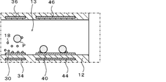
- FIG. 16 is a partial cross-sectional view showing another configuration for generating an electric field on each collection electrode 30, 40.
- FIG. 2 is a cross-sectional view showing a schematic configuration of a particulate number detector 110.
- FIG. 1 is a cross-sectional view showing a schematic configuration of the particle number detector 10
- FIG. 2 is a perspective view of the charge generation unit 20. As shown in FIG. 1
- the fine particle number detector 10 measures the number of fine particles contained in a gas (for example, an exhaust gas of a car).
- the particle number detector 10 includes a housing 12, a gas temperature measuring unit 14, a charge generating unit 20, an excess charge collecting electrode 30, a charged particle collecting electrode 40, a heater 50, and a heater temperature measuring unit. And a control unit 60.
- the housing 12 is made of an insulating material and has an air passage 13.
- the air passage 13 penetrates the housing 12 from one opening 13a to the other opening 13b.
- a ceramic material is mentioned, for example.
- the type of ceramic material is not particularly limited, and examples thereof include alumina, aluminum nitride, silicon carbide, mullite, zirconia, titania, silicon nitride, magnesia, glass, and mixtures thereof.
- the housing 12 preferably has a thermal conductivity [W / m ⁇ K] at 20 ° C. of 3 or more and 200 or less.
- the charge generating portion 20 In the air passage 13, from the upstream side to the downstream side of the gas flow (here, from the opening 13a to the opening 13b), the charge generating portion 20, the excess charge collection electrode 30, and the charged particle collection electrode 40 Are arranged in this order.
- the gas temperature measurement unit 14 is an element that measures the temperature Ta of the gas passing through the air passage 13.
- the gas temperature measurement unit 14 is installed on the inner surface of the air passage 13 via a heat insulating member.
- the charge generating unit 20 is provided to generate a charge in the air passage 13.
- the charge generation unit 20 has a discharge electrode 22 and two induction electrodes 24, 24.
- the discharge electrode 22 is provided along the inner surface of the air passage 13, and as shown in FIG. 2, has a plurality of fine protrusions 22a around the rectangular shape.
- the two induction electrodes 24, 24 are rectangular electrodes, and are embedded in the wall (housing 12) of the air passage 13 so as to be parallel to the discharge electrode 22 at an interval.
- the high frequency high voltage (for example, pulse voltage etc.) of the discharge power supply 26 is applied between the discharge electrode 22 and the two induction electrodes 24, 24 so as to cause air potential by the potential difference between both electrodes. Discharge occurs.
- the atmospheric discharge ionizes the gas present around the discharge electrode 22 to generate positive or negative charges 18.
- the material used for the discharge electrode 22 is preferably a metal having a melting point of 1500 ° C. or more from the viewpoint of heat resistance during discharge.
- Such metals can include titanium, chromium, iron, cobalt, nickel, niobium, molybdenum, tantalum, tungsten, iridium, palladium, platinum, gold or alloys thereof.
- platinum and gold which have a small ionization tendency, are preferable in terms of corrosion resistance.
- the discharge electrode 22 may be bonded to the inner surface of the air passage 13 via a glass paste, or may be formed as a sintered metal by firing a metal paste screen-printed on the inner surface of the air passage 13.
- the same material as the discharge electrode 22 can be used for the induction electrodes 24, 24.
- the fine particles 16 contained in the gas enter the air passage 13 through the opening 13a, and when passing through the charge generation unit 20, the charge 18 generated by the aerial discharge of the charge generation unit 20 is added to form charged fine particles P. Move downstream. Further, among the generated charges 18, those not added to the fine particles 16 move downstream as the charges 18.
- the excess charge collecting electrode 30 is an electrode that removes the charge 18 that has not been added to the particles 16, and is provided along the inner surface of the air passage 13.
- An electric field generating electrode 32 for collecting excess charge is provided at a position facing the excess charge collecting electrode 30 in the air passage 13.
- the electric field generating electrode 32 is also provided along the inner surface of the air passage 13.
- the charged particle collection electrode 40 is provided along the inner surface of the air passage 13.
- the charged particle collection electrode 40 collects charged particles P.
- An electric field generating electrode 42 for collecting charged particles is provided at a position facing the charged particle collection electrode 40 in the air passage 13.
- the electric field generating electrode 42 is also provided along the inner surface of the air passage 13.
- An electric field is generated on the top).
- the charged particles P are attracted to and collected by the charged particle collecting electrode 40 by the electric field.
- An ammeter 48 is connected to the charged particle collection electrode 40. The ammeter 48 detects the current flowing through the charged particle collection electrode 40 and outputs the detected current to the control unit 60.
- each collection electrode 30, 40 and the strength of the electric field on each collection electrode 30, 40 are determined by the charged particle collection electrode 40 without the charged particle P being collected by the excess charge collection electrode 30.
- the charge 18 which has not adhered to the particles 16 is set so as to be collected by the excess charge collecting electrode 30.
- the heater 50 is embedded in the wall (housing 12) of the air passage 13.
- the heater 50 is connected to a heater power supply 52.
- the heater power supply 52 applies a voltage between terminals provided at both ends of the heater 50 to cause a current to flow through the heater 50, thereby causing the heater 50 to generate heat.
- the material of the heater 50 is preferably a material having a relatively large temperature coefficient of resistance, for example, platinum, gold, silver, copper, iron, nickel, molybdenum, tungsten, etc. It is preferable to choose one.
- the material powder of the housing 12 for example, powder of ceramic such as alumina or zirconia may be added to the heater 50.
- the heater temperature measuring unit 54 is an element that measures the surface temperature T of the heater 50.
- the heater temperature measuring unit 54 is provided on the surface of the heater 50.
- the control unit 60 is configured by a known microcomputer including a CPU, a ROM, a RAM, and the like.
- the control unit 60 adjusts the voltage of the discharge power supply 26 and the voltage of the heater power supply 52, and inputs the temperature from the gas temperature measurement unit 14 or the heater temperature measurement unit 54, or the charged particle collection electrode 40 from the ammeter 48. Input the current flowing through the
- the control unit 60 obtains the number of particles per unit volume in the gas passing through the air passage 13 and displays the number on the display 62.
- the housing 12 provided with various electrodes 22, 24, 30, 32, 40, 42, the gas temperature measuring unit 14, the heater 50 and the heater temperature measuring unit 54 is a plurality of ceramic green sheets It can be produced using Specifically, for each of the plurality of ceramic green sheets, after providing a notch, a through hole, or a groove, screen printing an electrode or a wiring pattern, or arranging a temperature measuring element as necessary, laminating them And bake.
- the notches, the through holes and the grooves may be filled with a material (for example, an organic material) which is burnt off at the time of firing.
- the housing 12 provided with the various electrodes 22, 24, 30, 32, 40, 42, the gas temperature measuring unit 14, the heater 50, and the heater temperature measuring unit 54 is obtained.
- the discharge power source 26 is connected to the discharge electrode 22 and the induction electrodes 24 and 24, the ammeter 48 is connected to the charged particle collection electrode 40, and the heater power source 52 is connected to the heater 50.
- the control unit 40 is connected to the discharge power supply 26, the ammeter 48, the heater power supply 52, and the display 42.
- the particulate number detector 10 When detecting the number of particulates 16 contained in the exhaust gas of a car, the particulate number detector 10 is mounted in the exhaust pipe of the engine. At this time, the particulate number detector 10 is attached so that the exhaust gas flows into the air passage 13 from the opening 13a of the particulate number detector 10 and flows out from the opening 13b.
- the control unit 60 executes a particle number detection process for determining the number of particles 16 in the gas. At that time, the control unit 60 heats the air passage 13 by the heater 50. Specifically, the control unit 60 receives the gas temperature Ta from the gas temperature measurement unit 14 and the surface temperature T of the heater 50 from the heater temperature measurement unit 54, and the gas temperature Ta is set in advance. The voltage V H of the heater power supply 52 applied to the heater 50 is controlled so as to be a temperature. Control unit 60, to a temperature Ta of the gas reaches a set temperature, increasing the surface temperature T of the heater 50 is gradually increasing the voltage V H across the heater 50.
- the control unit 60 causes the temperature T of the heater 50 to be higher than the temperature Ta of the gas and lower than the incineration temperature (for example, 600 ° C.) of the particles 16.
- the heat amount (dissipated heat amount) Q H transferred from the housing 12 to the gas is represented by the following formula (1).
- the heat amount (supply heat amount) Q supplied to the heater 50 is expressed by the following equation (2).
- Equation (1) is called King's equation.
- Supply quantity Q is the same as the dissipation heat Q H by the cooling effect of the gas. Therefore, the right side of Formula (1) and the right side of Formula (2) are equal.
- a and b are constants
- T and Ta are measured values
- V H is a value adjusted by the control unit 60.
- the resistance R H of the heater 50 is a function of the temperature, and can be calculated from the surface temperature T of the heater 50. Therefore, the control unit 60 can obtain the flow velocity U of the gas from these equations.
- the flow rate q (volume flow rate) of the gas is a value obtained by multiplying the flow velocity U by the cross-sectional area S of the air passage 13. Therefore, the control unit 60 can also obtain the flow rate q of the gas
- the control unit 60 sets the distance between the discharge electrode 22 and the induction electrode 24 such that the number of charges 18 generated by the aerial discharge of the charge generation unit 20 exceeds the number of particles 16 expected to be contained in the gas.
- the voltage of the discharge power supply 26 applied to the The fine particles 16 in the gas that has flowed into the air passage 13 bear the charge 18 when passing through the charge generation unit 20 and become the charged fine particles P.
- the charged particles P move along the flow of the gas without being collected by the excess charge collection electrode 30, and then collected by the charged particle collection electrode 40.
- those not added to the fine particles 16 are collected by the excess charge collection electrode 30 and discarded to GND.
- the controller 60 obtains the number of particles per unit volume based on the detection current input from the ammeter 48 connected to the charged particle collection electrode 40 and the gas flow rate q, and displays the number on the display 62.
- the number of fine particles per unit volume in gas (unit: number / cc) is calculated by the following equation (3).
- the average charge number (unit: number) is an average value of the charges 18 attached to one particle 16 and can be calculated in advance from the measurement values of the microammeter and the particle number counter.
- the elementary charge amount (unit: C) is a constant which is also called elementary charge.
- the flow rate (unit: cc / s) is the flow rate q of the gas calculated as described above.
- Number of fine particles (detection current) / ⁇ (average charge number) ⁇ (elemental charge amount) ⁇ (flow rate) ⁇ (3)
- the heater 50 causes the charged particle collection electrode 40 to be at a predetermined particle burning temperature (e.g. By raising the temperature to 0 ° C., a refresh process is performed to burn off the fine particles 16 deposited on the charged fine particle collection electrode 40.
- the timing of the refresh process may be generated, for example, each time a predetermined period elapses, or may be generated every time the number of particles deposited on the charged particle collection electrode 40 reaches a predetermined number.
- the air passage 13 may be clogged to cause the gas flow rate to become zero every time it continues for a predetermined time.
- the control unit 60 does not execute the particle number detection process while the refresh process is being performed.
- the air passage 13 is heated by the heater 50.
- the flow rate q of the gas is determined based on
- a unit volume in the gas is determined based on the physical quantity (the current flowing to the charged particle collecting electrode 40) that changes according to the charge amount of the charged particles P collected by the charged particle collecting electrode 40 and the flow rate q of the gas. Determine the number of particles per shot.
- the number-of-particles detector 10 has a function of measuring the flow rate q of gas, the number of particles 16 per unit volume in the gas can be determined without preparing a flow meter separately. it can.
- the control unit 60 sets the surface temperature T of the heater 50 to a temperature higher than the temperature Ta of the gas and lower than the incineration temperature of the particulates 16.
- the surface temperature T of the heater 50 is made higher than the temperature Ta of the gas because the gas passing through the air passage 13 deprives the heat supplied to the housing 12 by the heater 50.
- the surface temperature of the heater 50 is made lower than the incineration temperature of the particles in order to prevent the particles from being incinerated. In this way, the number of particles 16 can be determined more accurately.
- the flow rate of gas is determined by the principle of a so-called thermal flow meter, so the heater 50 can be used both for detecting the flow rate of gas and refreshing the charged particle collection electrode 40.
- the discharge electrode 22 is provided along the inner surface of the air passage 13, and the induction electrode 24 is embedded in the wall (housing 12) of the air passage 13. Therefore, the flow of gas passing through the air passage 13 is unlikely to be blocked by the charge generation unit 20. Therefore, the gas flow rate can be determined more accurately.
- the housing 12 has a thermal conductivity [W / m ⁇ K] at 20 ° C. of 3 or more and 200 or less. Therefore, the heat of the heater 50 is conducted to the air passage 13 relatively quickly, and the responsiveness of the adjustment of the temperature Ta by the heater 50 becomes good. Further, since the housing 12 is made of ceramic, the heat resistance of the particle number detector 10 is improved.
- the heater 50 is embedded in the wall (housing 12) of the air passage 13. Therefore, the heat of the heater 50 is conducted to the air passage 13 more quickly than in the case where the heater is disposed outside the housing 12 or the like. Therefore, the responsiveness of the adjustment of the temperature Ta by the heater 50 is improved.
- the charged particle collecting electrode 40 collects the charged particles P using an electric field, the charged particles P can be efficiently collected on the charged particle collecting electrode 40.
- the electric field generating electrodes 32 and 42 are provided along the inner surface of the air passage 13 in the above-described embodiment, they may be embedded in the wall (the housing 12) of the air passage 13. Further, as shown in FIG. 3, instead of the electric field generating electrode 32, a pair of electric field generating electrodes 34 and 36 are embedded in the wall of the air passage 13 so as to sandwich the surplus charge collecting electrode 30. Alternatively, the pair of electric field generating electrodes 44 and 46 may be embedded in the wall of the air passage 13 so as to sandwich the charged particle collecting electrode 40. In this case, when a voltage is applied to the pair of electric field generating electrodes 34 and 36 to generate an electric field on the surplus charge collecting electrode 30, the charges 18 are collected by the surplus charge collecting electrode 30. When a voltage is applied to the pair of electric field generating electrodes 44 and 46 to generate an electric field on the charged particle collecting electrode 40, the charged particles P are collected by the charged particle collecting electrode 40.
- the charge generation unit 20 is configured by the discharge electrode 22 provided along the inner surface of the air passage 13 and the two induction electrodes 24 and 24 embedded in the housing 12;
- any configuration may be used as long as it generates an electric charge.
- the induction electrodes 24, 24 instead of embedding the induction electrodes 24, 24 in the wall of the air passage 13, they may be provided along the inner surface of the air passage 13.
- the induction electrode 24 may be bonded to the inner surface of the air passage 13 via a glass paste, or the metal paste screen-printed on the inner surface of the air passage 13 may be fired to form a sintered metal.
- the charge generation portion may be configured of a needle electrode and a counter electrode.
- the heater 50 is embedded in the lower wall of the air passage 13, but may be embedded in the upper wall of the air passage 13, or may be embedded in the upper and lower walls of the air passage 13.
- the tubular or spiral heater 50 may be embedded in the housing 12.
- the heater 50 may be disposed on the outer surface of the housing 12 instead of being embedded in the housing 12.
- the gas temperature measurement unit 14 is attached to a position close to the inner surface of the air passage 13.
- the gas measurement unit 14 may be attached to a position close to the central axis of the air passage 13.
- the charge generation unit 20 is provided below the air passage 13.
- the charge generation unit 20 may be provided above the air passage 13, or may be provided on both upper and lower sides of the air passage 13.
- the electric field is generated on the charged particle collecting electrode 40, but even when the electric field is not generated, the distance between the portions of the air passage 13 where the charged particle collecting electrode 40 is provided If the thickness) is adjusted to a minute value (for example, 0.01 mm or more and less than 0.2 mm), it is possible to collect the charged particles P on the charged particle collection electrode 40. That is, since the charged fine particles P have intense Brownian motion, the charged fine particles P can be made to collide with the charged fine particle collecting electrode 40 and be collected by setting the flow channel thickness to a minute value. In this case, the field generating electrode 42 may not be provided.
- the number of particles per unit volume in the gas is determined using the number-of-particles detector 10.
- the number of particles per unit volume in the gas is calculated using the number-of-particles detector 110 shown in FIG. You may ask.
- the particle number detector 110 has the same configuration as the particle number detector 10 except that the charged particle collecting electrode 40 and the charge generating electrode 42 are omitted and the ammeter 48 is connected to the surplus charge collecting electrode 30 and the control unit 60.
- the same components as those of the particle number detector 10 are denoted by the same reference numerals.
- the ammeter 48 detects the current flowing through the excess charge collecting electrode 30 and outputs the current to the control unit 60.
- the voltage applied between the discharge electrode 22 and the induction electrode 24 is adjusted to generate a predetermined amount of charge 18 per unit time.
- the size of the excess charge collection electrode 30 and the strength of the electric field on the excess charge collection electrode 30 are such that the excess charge is collected by the excess charge collection electrode 30 but the charged particles P are not collected. Is set. Therefore, the charged fine particles P do not get collected by the excess charge collecting electrode 30 and come out of the opening 13 b of the air passage 13.
- the control unit 60 of the fine particle number detector 10 executes the fine particle number detection process, the temperature Ta of the gas and the surface of the heater 50 are in a state in which the air passage 13 is heated by the heater 50 as in the embodiment described above.
- the gas flow rate q is obtained.
- the number of particles per unit volume in the gas (unit: individual) based on the physical quantity (current) that changes in accordance with the charge amount of the excess charge collected by the excess charge collection electrode 30 and the flow rate q of the gas Calculate / cc)
- the difference between the total number of charges 18 generated and the number of surplus charges is divided by the average charge number of the charged fine particles P to obtain the number of charged fine particles, which is divided by the flow rate q. Since the number-of-particles detector 110 also has a function of measuring the flow rate of the gas, the number of particles per unit volume in the gas can be determined without separately preparing a flow meter.
- the present invention is applicable to, for example, a particle number detector for determining the number of particles in a gas.
Landscapes
- Chemical & Material Sciences (AREA)
- Physics & Mathematics (AREA)
- General Physics & Mathematics (AREA)
- General Health & Medical Sciences (AREA)
- Immunology (AREA)
- Life Sciences & Earth Sciences (AREA)
- Analytical Chemistry (AREA)
- Biochemistry (AREA)
- Pathology (AREA)
- Health & Medical Sciences (AREA)
- Dispersion Chemistry (AREA)
- Chemical Kinetics & Catalysis (AREA)
- Electrochemistry (AREA)
- Fluid Mechanics (AREA)
- Acoustics & Sound (AREA)
- Electromagnetism (AREA)
- Other Investigation Or Analysis Of Materials By Electrical Means (AREA)
Abstract
微粒子数検出器は、ガス中の微粒子の数を求める微粒子数検出処理を実行する制御部を備える。制御部は、微粒子数検出処理を実行する際には、ヒータによって通気路を加熱した状態で、ガスの温度とヒータの表面温度との差とヒータに供給される熱量とに基づいてガスの流量を求め、帯電微粒子捕集電極に捕集された帯電微粒子の電荷量に応じて変化する物理量とガスの流量とに基づいてガス中の単位体積当たりの微粒子の数を求める。
Description
本発明は、微粒子数検出器に関する。
微粒子数検出器としては、電荷発生素子でコロナ放電によりイオンを発生させ、そのイオンにより被測定ガス中の微粒子を帯電し、帯電した微粒子を捕集し、捕集された微粒子の電荷の量に基づいて微粒子の個数を測定するものが知られている。また、こうした微粒子数検出器において、捕集された微粒子をヒータで加熱して焼却したり、ガスの流入孔や排出孔に溜まった微粒子をヒータで加熱して焼却したりすることが提案されている(例えば特許文献1参照)。
ところで、被測定ガス中の単位体積当たりの微粒子の数を求めるには、被測定ガスの流量を用いる必要がある。しかしながら、特許文献1の微粒子数検出器は、被測定ガスの流量を測定する機能を備えていないため、被測定ガス中の単位体積当たりの微粒子の数を求めることができなかった。
本発明はこのような課題を解決するためになされたものであり、ガス中の単位体積当たりの微粒子の数を求めることを主目的とする。
本発明の第1の微粒子数検出器は、
通気路を有する筐体と、
前記通気路内を通過するガスの温度を測定するガス測温部と、
前記通気路内で気中放電により電荷を発生し、前記通気路内を通過するガス中の微粒子に前記電荷を付加して帯電微粒子にする電荷発生部と、
前記帯電微粒子を捕集する帯電微粒子捕集電極と、
前記通気路を加熱可能なヒータと、
前記ヒータの表面温度を測定するヒータ測温部と、
前記ガス中の前記微粒子の数を求める微粒子数検出処理を実行する制御部と、
を備え、
前記制御部は、前記微粒子数検出処理を実行する際には、前記ヒータによって前記通気路を加熱した状態で、前記ガスの温度と前記ヒータの表面温度との差と前記ヒータに供給される熱量とに基づいて前記ガスの流量を求め、前記帯電微粒子捕集電極に捕集された前記帯電微粒子の電荷量に応じて変化する物理量と前記ガスの流量とに基づいて前記ガス中の単位体積当たりの前記微粒子の数を求める、
ものである。
通気路を有する筐体と、
前記通気路内を通過するガスの温度を測定するガス測温部と、
前記通気路内で気中放電により電荷を発生し、前記通気路内を通過するガス中の微粒子に前記電荷を付加して帯電微粒子にする電荷発生部と、
前記帯電微粒子を捕集する帯電微粒子捕集電極と、
前記通気路を加熱可能なヒータと、
前記ヒータの表面温度を測定するヒータ測温部と、
前記ガス中の前記微粒子の数を求める微粒子数検出処理を実行する制御部と、
を備え、
前記制御部は、前記微粒子数検出処理を実行する際には、前記ヒータによって前記通気路を加熱した状態で、前記ガスの温度と前記ヒータの表面温度との差と前記ヒータに供給される熱量とに基づいて前記ガスの流量を求め、前記帯電微粒子捕集電極に捕集された前記帯電微粒子の電荷量に応じて変化する物理量と前記ガスの流量とに基づいて前記ガス中の単位体積当たりの前記微粒子の数を求める、
ものである。
この微粒子数検出器は、微粒子数検出処理を実行する際には、ヒータによって通気路を加熱した状態にする。その状態で、ガスの温度とヒータの表面温度との差とヒータに供給される熱量とに基づいてガスの流量を求める。また、帯電微粒子捕集電極に捕集された帯電微粒子の電荷量に応じて変化する物理量とガスの流量とに基づいてガス中の単位体積当たりの微粒子の数を求める。本発明の第1の微粒子数検出器は、ガスの流量を測定する機能を備えているため、別途流量計を用意しなくても、ガス中の単位体積当たりの微粒子の数を求めることができる。
本発明の第1の微粒子数検出器において、前記制御部は、前記微粒子数検出処理を実行していないときに、前記ヒータによって前記帯電微粒子捕集電極を所定の微粒子焼却温度に昇温することにより、前記帯電微粒子捕集電極に堆積した前記微粒子を焼却するリフレッシュ処理を実行してもよい。こうすれば、ヒータを、ガスの流量の検出と帯電微粒子捕集電極のリフレッシュの両方に利用することができる。
本発明の第2の微粒子数検出器は、
通気路を有する筐体と、
前記通気路内を通過するガスの温度を測定するガス測温部と、
前記通気路内で気中放電により電荷を発生し、前記通気路内を通過するガス中の微粒子に前記電荷を付加して帯電微粒子にする電荷発生部と、
前記微粒子に帯電しなかった余剰電荷を捕集する余剰電荷捕集電極と、
前記通気路を加熱可能なヒータと、
前記ヒータの表面温度を測定するヒータ測温部と、
前記ガス中の前記微粒子の数を求める微粒子数検出処理を実行する制御部と、
を備え、
前記制御部は、前記微粒子数検出処理を実行する際には、前記ヒータによって前記通気路を加熱した状態で、前記ガスの温度と前記ヒータの表面温度との差と前記ヒータに供給される熱量とに基づいて前記ガスの流量を求め、前記余剰電荷捕集電極に捕集された前記余剰電荷の電荷量に応じて変化する物理量と前記ガスの流量とに基づいて前記ガス中の単位体積当たりの前記微粒子の数を求める、
ものである。
通気路を有する筐体と、
前記通気路内を通過するガスの温度を測定するガス測温部と、
前記通気路内で気中放電により電荷を発生し、前記通気路内を通過するガス中の微粒子に前記電荷を付加して帯電微粒子にする電荷発生部と、
前記微粒子に帯電しなかった余剰電荷を捕集する余剰電荷捕集電極と、
前記通気路を加熱可能なヒータと、
前記ヒータの表面温度を測定するヒータ測温部と、
前記ガス中の前記微粒子の数を求める微粒子数検出処理を実行する制御部と、
を備え、
前記制御部は、前記微粒子数検出処理を実行する際には、前記ヒータによって前記通気路を加熱した状態で、前記ガスの温度と前記ヒータの表面温度との差と前記ヒータに供給される熱量とに基づいて前記ガスの流量を求め、前記余剰電荷捕集電極に捕集された前記余剰電荷の電荷量に応じて変化する物理量と前記ガスの流量とに基づいて前記ガス中の単位体積当たりの前記微粒子の数を求める、
ものである。
この微粒子数検出器は、微粒子数検出処理を実行する際には、ヒータによって通気路を加熱した状態にする。その状態で、ガスの温度とヒータの表面温度との差とヒータに供給される熱量とに基づいてガスの流量を求める。また、余剰電荷捕集電極に捕集された余剰電荷の電荷量に応じて変化する物理量とガスの流量とに基づいてガス中の単位体積当たりの微粒子の数を求める。本発明の第2の微粒子数検出器は、ガスの流量を測定する機能を備えているため、別途流量計を用意しなくても、ガス中の単位体積当たりの微粒子の数を求めることができる。
なお、本明細書において、「電荷」とは、正電荷や負電荷のほかイオンを含むものとする。「物理量」とは、電荷量に応じて変化するパラメータであればよく、例えば電流などが挙げられる。「ヒータに供給される熱量」は、ヒータに流れる電流、ヒータの両端に印加する電圧及びヒータの抵抗のうちのいずれか2つの物理量によって表すことができる。そのため、「ヒータに供給される熱量」は、熱量そのものであってもよいし、ヒータに流れる電流、ヒータの両端に印加する電圧及びヒータの抵抗のうちのいずれか2つの物理量であってもよい。
本発明の第1又は第2の微粒子数検出器において、前記制御部は、前記微粒子数検出処理を実行する際には、前記ヒータの表面温度を前記ガスの温度よりも高く前記微粒子の焼却温度よりも低い温度に設定してもよい。ヒータの表面温度をガスの温度よりも高くするのは、通気路を通過するガスがヒータによって供給された熱を奪うからである。ヒータの表面温度を微粒子の焼却温度よりも低くするのは、微粒子が焼却されてしまうのを防止するためである。このようにすれば、微粒子の数をより正確に求めることができる。
本発明の第1又は第2の微粒子数検出器において、前記電荷発生部は、放電電極と誘導電極とを含み、前記放電電極は、前記通気路の内面に沿って設けられ、前記誘導電極は、前記筐体に埋設されているか前記通気路の内面に沿って設けられていてもよい。こうすれば、通気路を通過するガスの流れが電荷発生部によって妨げられにくいため、ガスの流量をより正確に求めることができる。なお、放電電極や誘導電極は、通気路の内面に無機材料で接合されていてもよいし、通気路の内面に焼結により接合されていてもよい。
本発明の第1又は第2の微粒子数検出器において、前記筐体は、20℃における熱伝導率[W/m・K]が3以上200以下であってもよい。こうすれば、ヒータの熱が比較的速やかに通気路に伝導されるため、ヒータによる通気路の温度調整の応答性が良好になる。
本発明の第1又は第2の微粒子数検出器において、前記筐体は、セラミック製であってもよい。こうすれば、セラミックは耐熱性に優れるため、微粒子数検出器の耐熱性が向上する。セラミックとしては、例えばアルミナや窒化アルミニウムなどが挙げられる。なお、20℃における熱伝導率は、アルミナが30[W/m・K]、窒化アルミニウムが150[W/m・K]である。
本発明の第1又は第2の微粒子数検出器において、前記ヒータは、前記筐体に埋設されていてもよい。こうすれば、ヒータが筐体の外側に配置されている場合に比べて、ヒータの熱が速やかに通気路に伝導されるため、ヒータによる通気路の温度調整の応答性が良好になる。
本発明の好適な実施形態を図面を参照しながら以下に説明する。図1は微粒子数検出器10の概略構成を表す断面図、図2は電荷発生部20の斜視図である。
微粒子数検出器10は、ガス(例えば自動車の排ガス)に含まれる微粒子の数を計測するものである。この微粒子数検出器10は、筐体12と、ガス測温部14と、電荷発生部20と、余剰電荷捕集電極30と、帯電微粒子捕集電極40と、ヒータ50と、ヒータ測温部54と、制御部60とを備えている。
筐体12は、絶縁材料からなり、通気路13を有している。通気路13は、一方の開口13aから他方の開口13bまで筐体12を貫通している。絶縁材料としては、例えばセラミック材料が挙げられる。セラミック材料の種類は、特に限定するものではないが、例えばアルミナや窒化アルミニウム、炭化珪素、ムライト、ジルコニア、チタニア、窒化珪素、マグネシア、ガラス、またはこれらの混合物などが挙げられる。筐体12は、20℃における熱伝導率[W/m・K]が3以上200以下であることが好ましい。通気路13内には、ガスの流れの上流側から下流側に向かって(ここでは開口13aから開口13bに向かって)、電荷発生部20、余剰電荷捕集電極30及び帯電微粒子捕集電極40がこの順に並ぶように設けられている。
ガス測温部14は、通気路13内を通過するガスの温度Taを測定する素子である。ガス測温部14は、通気路13の内面に断熱部材を介して設置されている。
電荷発生部20は、通気路13内に電荷を発生するように設けられている。電荷発生部20は、放電電極22と2つの誘導電極24,24とを有している。放電電極22は、通気路13の内面に沿って設けられ、図2に示すように、矩形の周囲に複数の微細突起22aを有している。2つの誘導電極24,24は、矩形電極であり、通気路13の壁(筐体12)に間隔をあけて放電電極22と平行となるように埋設されている。電荷発生部20では、放電電極22と2つの誘導電極24,24との間に放電用電源26の高周波高電圧(例えばパルス電圧等)が印加されることで、両電極間の電位差による気中放電が発生する。このとき、筐体12のうち放電電極22と誘導電極24,24との間の部分が誘電体層の役割を果たす。この気中放電によって、放電電極22の周囲に存在するガスがイオン化されて正又は負の電荷18が発生する。放電電極22に用いられる材料としては、放電時の耐熱性の点から融点が1500℃以上の金属が好ましい。こうした金属としては、チタン、クロム、鉄、コバルト、ニッケル、ニオブ、モリブデン、タンタル、タングステン、イリジウム、パラジウム、白金、金またはそれらの合金を挙げることができる。中でも、耐腐食性の点から、イオン化傾向が小さい白金と金が好ましい。放電電極22は、ガラスペーストを介して通気路13の内面に接合してもよいし、通気路13の内面にスクリーン印刷した金属ペーストを焼成して燒結金属として形成してもよい。誘導電極24,24も、放電電極22と同様の材料を用いることができる。
ガスに含まれる微粒子16は、開口13aから通気路13内に入り、電荷発生部20を通過する際に電荷発生部20の気中放電によって発生した電荷18が付加されて帯電微粒子Pとなって下流に移動する。また、発生した電荷18のうち微粒子16に付加されなかったものは、電荷18のまま下流に移動する。
余剰電荷捕集電極30は、微粒子16に付加されなかった電荷18を除去する電極であり、通気路13の内面に沿って設けられている。通気路13のうち、余剰電荷捕集電極30と対向する位置には余剰電荷捕集用の電界発生電極32が設けられている。この電界発生電極32も、通気路13の内面に沿って設けられている。電界発生電極32と余剰電荷捕集電極30との間に図示しない電界発生用電源の電圧が印加されると、電界発生電極32と余剰電荷捕集電極30との間(余剰電荷捕集電極30上)に電界が発生する。電荷発生部20の気中放電によって発生した電荷18のうち微粒子16に付加されなかったものは、この電界によって余剰電荷捕集電極30に引き寄せられて捕集され、GND(グランド)に捨てられる。
帯電微粒子捕集電極40は、通気路13の内面に沿って設けられている。帯電微粒子捕集電極40は、帯電微粒子Pを捕集する。通気路13のうち帯電微粒子捕集電極40と対向する位置には、帯電微粒子捕集用の電界発生電極42が設けられている。この電界発生電極42も、通気路13の内面に沿って設けられている。電界発生電極42と帯電微粒子捕集電極40との間に図示しない電界発生用電源の電圧が印加されると、電界発生電極42と帯電微粒子捕集電極40との間(帯電微粒子捕集電極40上)に電界が発生する。帯電微粒子Pは、この電界によって帯電微粒子捕集電極40に引き寄せられて捕集される。帯電微粒子捕集電極40には、電流計48が接続されている。この電流計48は、帯電微粒子捕集電極40を流れる電流を検出して制御部60に出力する。
各捕集電極30,40のサイズや各捕集電極30,40上の電界の強さは、帯電微粒子Pが余剰電荷捕集電極30に捕集されることなく帯電微粒子捕集電極40に捕集されるように、また、微粒子16に付着しなかった電荷18が余剰電荷捕集電極30に捕集されるように、設定されている。
ヒータ50は、通気路13の壁(筐体12)に埋設されている。ヒータ50は、ヒータ電源52に接続されている。ヒータ電源52は、ヒータ50の両端に設けられた端子同士の間に電圧を印加してヒータ50に電流を流すことにより、ヒータ50を発熱させる。ヒータ50の材料は、抵抗温度係数の比較的大きな材料が好ましく、例えば白金、金、銀、銅、鉄、ニッケル、モリブデン、タングステンなどが挙げられるが、筐体12の材料と熱膨張係数の近いものを選ぶのが好ましい。また、ヒータ50と筐体12との熱膨張係数の差を低減させるために、ヒータ50に筐体12の材料粉末(例えばアルミナやジルコニア等のセラミックの粉末)を添加してもよい。
ヒータ測温部54は、ヒータ50の表面温度Tを測定する素子である。ヒータ測温部54は、ヒータ50の表面に設けられている。
制御部60は、CPU、ROM、RAMなどからなる周知のマイクロコンピュータによって構成されている。制御部60は、放電用電源26の電圧やヒータ電源52の電圧を調整すると共に、ガス測温部14やヒータ測温部54から温度を入力したり、電流計48から帯電微粒子捕集電極40を流れる電流を入力したりする。制御部60は、通気路13を通過するガス中の単位体積当たりの微粒子数を求め、ディスプレイ62に表示する。
次に、微粒子数検出器10の製造例について説明する。微粒子数検出器10のうち、各種電極22,24,30,32,40,42、ガス測温部14、ヒータ50及びヒータ測温部54を備えた筐体12は、複数枚のセラミックグリーンシートを用いて作製することができる。具体的には、複数枚のセラミックグリーンシートの各々について、必要に応じて切欠や貫通孔や溝を設けたり電極や配線パターンをスクリーン印刷したり測温素子を配置したりした後、それらを積層して焼成する。なお、切欠や貫通孔や溝については、焼成時に焼失するような材料(例えば有機材料)で充填しておいてもよい。こうして、各種電極22,24,30,32,40,42、ガス測温部14、ヒータ50及びヒータ測温部54を備えた筐体12を得る。続いて、放電用電源26を放電電極22と誘導電極24,24に接続し、電流計48を帯電微粒子捕集電極40に接続し、ヒータ電源52をヒータ50に接続する。また、制御部40を放電用電源26、電流計48、ヒータ電源52及びディスプレイ42に接続する。こうすることにより、微粒子数検出器10を作製することができる。
次に、微粒子数検出器10の使用例について説明する。自動車の排ガスに含まれる微粒子16の数を検出する場合、エンジンの排気管内に微粒子数検出器10を取り付ける。このとき、排ガスが微粒子数検出器10の開口13aから通気路13に流入し、開口13bから流出するように微粒子数検出器10を取り付ける。
制御部60は、ガス中の微粒子16の数を求める微粒子数検出処理を実行する。その際、制御部60は、ヒータ50によって通気路13を加熱する。具体的には、制御部60は、ガス測温部14からガスの温度Taを入力すると共にヒータ測温部54からヒータ50の表面温度Tを入力し、ガスの温度Taが予め定められた設定温度になるように、ヒータ50に印加されるヒータ電源52の電圧VHを制御する。制御部60は、ガスの温度Taが設定温度に達するまで、ヒータ50の両端の電圧VHを徐々に高くしてヒータ50の表面温度Tを上昇させる。ガスの流速が速い場合、ガスが筐体12から奪う熱が多くなり、ガスの流速が遅い場合には、ガスが筐体12から奪う熱が少なくなる。そのため、ガスの流速が速いほどヒータ50の表面温度Tは高くなる。また、制御部60は、ヒータ50の温度Tを、ガスの温度Taよりも高く、微粒子16の焼却温度(例えば600℃)よりも低い温度になるようにする。
筐体12からガスに移動する熱量(放散熱量)QHは下記式(1)で表される。ヒータ50に供給される熱量(供給熱量)Qは下記式(2)で表される。式(1)はKingの式と呼ばれる。供給熱量Qは、ガスの冷却作用による放散熱量QHと同じになる。そのため、式(1)の右辺と式(2)の右辺は等しい。ここで、a,bは定数であり、T,Taは測定値であり、VH は制御部60によって調整される値である。ヒータ50の抵抗RHは、温度の関数であるため、ヒータ50の表面温度Tから算出することができる。したがって、制御部60は、これらの式からガスの流速Uを求めることができる。ガスの流量q(体積流量)は、流速Uに通気路13の断面積Sを乗じた値であるため、制御部60は、これらの式からガスの流量qも求めることができる。
QH=(a+b×U1/2)×(T-Ta) …(1)
a,b:ガス及びヒータ50の形状により決まる定数
U:ガスの流速
Ta:ガスの温度
T:ヒータ50の表面温度
Q=VH 2/RH …(2)
VH:ヒータ50の両端の電圧
RH:ヒータ50の抵抗
a,b:ガス及びヒータ50の形状により決まる定数
U:ガスの流速
Ta:ガスの温度
T:ヒータ50の表面温度
Q=VH 2/RH …(2)
VH:ヒータ50の両端の電圧
RH:ヒータ50の抵抗
制御部60は、電荷発生部20の気中放電によって発生される電荷18の数がガス中に含まれると予想される微粒子16の数を上回るように、放電電極22と誘導電極24との間に印加される放電用電源26の電圧を調整する。通気路13内に流入したガス中の微粒子16は、電荷発生部20を通過する際に電荷18を帯びて帯電微粒子Pになる。帯電微粒子Pは、余剰電荷捕集電極30に捕集されることなくガスの流れに沿って移動し、その後、帯電微粒子捕集電極40に捕集される。一方、電荷発生部20で発生した電荷18のうち微粒子16に付加しなかったものは、余剰電荷捕集電極30に捕集されてGNDに捨てられる。
制御部60は、帯電微粒子捕集電極40に接続された電流計48から入力した検出電流とガスの流量qとに基づいて単位体積当たりの微粒子数を求め、その数をディスプレイ62に表示する。ガス中の単位体積当たりの微粒子数(単位:個/cc)は、下記式(3)により算出される。式(3)中、検出電流(単位:A(=C/s))は、電流計48から入力した電流である。平均帯電数(単位:個)は、1つの微粒子16に付着する電荷18の平均値であり、予め微小電流計と粒子数カウンタの測定値から算出可能な値である。素電荷量(単位:C)は、電荷素量とも呼ばれる定数である。流量(単位:cc/s)は、上述したように算出されるガスの流量qである。
微粒子数=(検出電流)/{(平均帯電数)×(素電荷量)×(流量)}…(3)
微粒子数=(検出電流)/{(平均帯電数)×(素電荷量)×(流量)}…(3)
また、制御部60は、微粒子数検出処理を実行していない期間において、リフレッシュ処理のタイミングになったならば、ヒータ50によって帯電微粒子捕集電極40を所定の微粒子焼却温度(例えば600℃とか700℃)に昇温することにより、帯電微粒子捕集電極40に堆積した微粒子16を焼却するリフレッシュ処理を実行する。リフレッシュ処理のタイミングは、例えば、所定期間が経過するごとに発生するようにしてもよいし、帯電微粒子捕集電極40に堆積した微粒子数が所定数に達するごとに発生するようにしてもよいし、更に通気路13に詰まりが生じてガスの流量がゼロになった状態が所定時間継続したごとに発生するようにしてもよい。制御部60は、リフレッシュ処理の実行中は微粒子数検出処理を実行しない。
以上説明した微粒子数検出器10では、微粒子数検出処理を実行する際には、ヒータ50によって通気路13を加熱した状態にする。その状態で、ガスの温度Taとヒータ50の表面温度Tとの差(=T-Ta)とヒータ50に供給される熱量Q(例えばヒータ50の両端の電圧VHとヒータ50の抵抗RH)とに基づいてガスの流量qを求める。また、帯電微粒子捕集電極40に捕集された帯電微粒子Pの電荷量に応じて変化する物理量(帯電微粒子捕集電極40に流れる電流)とガスの流量qとに基づいてガス中の単位体積当たりの微粒子の数を求める。このように、微粒子数検出器10は、ガスの流量qを測定する機能を備えているため、別途流量計を用意しなくても、ガス中の単位体積当たりの微粒子16の数を求めることができる。
また、制御部60は、微粒子数検出処理を実行する際には、ヒータ50の表面温度Tをガスの温度Taよりも高く微粒子16の焼却温度よりも低い温度に設定する。ヒータ50の表面温度Tをガスの温度Taよりも高くするのは、通気路13内を通過するガスがヒータ50によって筐体12に供給された熱を奪うからである。ヒータ50の表面温度を微粒子の焼却温度よりも低くするのは、微粒子が焼却されてしまうのを防止するためである。このようにすれば、微粒子16の数をより正確に求めることができる。
更に、微粒子数検出器10では、ガスの流量をいわゆる熱式流量計の原理によって求めるため、ヒータ50をガスの流量の検出と帯電微粒子捕集電極40のリフレッシュの両方に兼用することができる。
更にまた、放電電極22は、通気路13の内面に沿って設けられ、誘導電極24は、通気路13の壁(筐体12)に埋設されている。そのため、通気路13を通過するガスの流れが電荷発生部20によって妨げられにくい。したがって、ガスの流量をより正確に求めることができる。
そしてまた、筐体12は、20℃における熱伝導率[W/m・K]が3以上200以下である。そのため、ヒータ50の熱が比較的速やかに通気路13に伝導され、ヒータ50による温度Taの調整の応答性が良好になる。また、筐体12はセラミック製であるため、微粒子数検出器10の耐熱性が向上する。
そして更に、ヒータ50は、通気路13の壁(筐体12)に埋設されている。そのため、ヒータが筐体12の外側に配置されている場合等に比べて、ヒータ50の熱が速やかに通気路13に伝導される。したがって、ヒータ50による温度Taの調整の応答性が良好になる。
そして更にまた、帯電微粒子捕集電極40は電界を利用して帯電微粒子Pを捕集するため、帯電微粒子捕集電極40に帯電微粒子Pを効率よく捕集することができる。
なお、本発明は上述した実施形態に何ら限定されることはなく、本発明の技術的範囲に属する限り種々の態様で実施し得ることはいうまでもない。
例えば、上述した実施形態では、電界発生電極32,42を通気路13の内面に沿って設けたが、通気路13の壁(筐体12)に埋設してもよい。また、図3に示すように、電界発生電極32の代わりに、余剰電荷捕集電極30を挟むように一対の電界発生電極34,36を通気路13の壁に埋設し、電界発生電極42の代わりに、帯電微粒子捕集電極40を挟むように一対の電界発生電極44,46を通気路13の壁に埋設してもよい。この場合、一対の電界発生電極34,36に電圧を印加して余剰電荷捕集電極30上に電界を発生させると、余剰電荷捕集電極30に電荷18が捕集される。また、一対の電界発生電極44,46に電圧を印加して帯電微粒子捕集電極40上に電界を発生させると、帯電微粒子捕集電極40に帯電微粒子Pが捕集される。
上述した実施形態では、電荷発生部20として、通気路13の内面に沿って設けられた放電電極22と筐体12に埋設された2つの誘導電極24,24とにより構成したが、気中放電により電荷を発生するものであれば特にどのような構成でも構わない。例えば、誘導電極24,24を通気路13の壁に埋設する代わりに、通気路13の内面に沿って設けてもよい。その場合、誘導電極24は、ガラスペーストを介して通気路13の内面に接合してもよいし、通気路13の内面にスクリーン印刷した金属ペーストを焼成して燒結金属として形成してもよい。あるいは、国際公開第2015/146456号パンフレットに記載されているように、電荷発生部を針状電極と対向電極とで構成してもよい。
上述した実施形態では、ヒータ50を通気路13の下側の壁に埋設したが、通気路13の上側の壁に埋設してもよいし、通気路13の上下両側の壁に埋設してもよいし、管状又は螺旋状のヒータ50を筐体12に埋設してもよい。また、ヒータ50を筐体12に埋設する代わりに筐体12の外面に配置してもよい。
上述した実施形態では、ガス測温部14を通気路13の内面に近い位置に取り付けたが、ガス測温部14を通気路13の中心軸に近い位置に取り付けてもよい。
上述した実施形態では、電荷発生部20を通気路13の下側に設けたが、通気路13の上側に設けてもよいし、通気路13の上下両側のそれぞれに設けてもよい。
上述した実施形態では、帯電微粒子捕集電極40上に電界を発生させたが、電界を発生させない場合でも、通気路13のうち帯電微粒子捕集電極40が設けられている部分の間隔(流路厚)を微小な値(例えば0.01mm以上0.2mm未満)に調整すれば、帯電微粒子捕集電極40に帯電微粒子Pを捕集することは可能である。すなわち、帯電微粒子Pはブラウン運動が激しいため、流路厚を微小な値にすることで帯電微粒子Pを帯電微粒子捕集電極40に衝突させて捕集することができる。この場合、電界発生電極42を備えなくてもよい。
上述した実施形態では、微粒子数検出器10を用いてガス中の単位体積当たりの微粒子数を求めたが、図4に示す微粒子数検出器110を用いてガス中の単位体積当たりの微粒子数を求めてもよい。微粒子数検出器110は、帯電微粒子捕集電極40及び電荷発生電極42を省略し電流計48を余剰電荷捕集電極30及び制御部60に接続した以外は微粒子数検出器10と同様の構成であるため、微粒子数検出器10と同じ構成要素については同じ符号を付した。電流計48は、余剰電荷捕集電極30を流れる電流を検出して制御部60に出力する。放電電極22と誘導電極24との間に印加される電圧は、単位時間当たりに所定量の電荷18が発生するように調整される。余剰電荷捕集電極30のサイズや余剰電荷捕集電極30上の電界の強さは、余剰電荷捕集電極30に余剰電荷は捕集されるが帯電微粒子Pは捕集されることのないように、設定される。そのため、帯電微粒子Pは余剰電荷捕集電極30に捕集されることなく通気路13の開口13bから外へ出ていく。微粒子数検出器10の制御部60は、微粒子数検出処理を実行する際には、上述した実施形態と同様、ヒータ50によって通気路13を加熱した状態で、ガスの温度Taとヒータ50の表面温度Tとの差(=T-Ta)とヒータ50に供給される熱量Qとに基づいてガスの流量qを求める。また、余剰電荷捕集電極30に捕集された余剰電荷の電荷量に応じて変化する物理量(電流)とガスの流量qとに基づいてガス中の単位体積当たりの微粒子の数(単位:個/cc)を求める。ガス中の単位体積当たりの微粒子数は、余剰電荷捕集電極30に流れる電流に基づいて単位時間当たりの余剰電荷の数(=電流/素電荷量)を求め、単位時間当たりに電荷発生部20で発生した電荷18の総数からその余剰電荷の数を引いた差を帯電微粒子Pの平均帯電数で除して帯電微粒子数とし、それを流量qで除すことにより、得られる。この微粒子数検出器110も、ガスの流量を測定する機能を備えているため、別途流量計を用意しなくても、ガス中の単位体積当たりの微粒子の数を求めることができる。
本出願は、2017年8月22日に出願された日本国特許出願第2017-159492号を優先権主張の基礎としており、引用によりその内容の全てが本明細書に含まれる。
本発明は、例えばガス中の微粒子の数を求める微粒子数検出器に利用可能である。
10,110 微粒子数検出器、12 筐体、13 通気路、13a 一方の開口、13b 他方の開口、14 ガス測温部、16 微粒子、18 電荷、20 電荷発生部、22 放電電極、22a 微細突起、24 誘導電極、26 放電用電源、30 余剰電荷捕集電極、32,34,36 電界発生電極、40 帯電微粒子捕集電極、42,44,46 電界発生電極、48 電流計、50 ヒータ、52 ヒータ電源、54 ヒータ測温部、60 制御部、62 ディスプレイ、P 帯電微粒子。
Claims (8)
- 通気路を有する筐体と、
前記通気路内を通過するガスの温度を測定するガス測温部と、
前記通気路内で気中放電により電荷を発生し、前記通気路内を通過するガス中の微粒子に前記電荷を付加して帯電微粒子にする電荷発生部と、
前記帯電微粒子を捕集する帯電微粒子捕集電極と、
前記通気路を加熱可能なヒータと、
前記ヒータの表面温度を測定するヒータ測温部と、
前記ガス中の前記微粒子の数を求める微粒子数検出処理を実行する制御部と、
を備え、
前記制御部は、前記微粒子数検出処理を実行する際には、前記ヒータによって前記通気路を加熱した状態で、前記ガスの温度と前記ヒータの表面温度との差と前記ヒータに供給される熱量とに基づいて前記ガスの流量を求め、前記帯電微粒子捕集電極に捕集された前記帯電微粒子の電荷量に応じて変化する物理量と前記ガスの流量とに基づいて前記ガス中の単位体積当たりの前記微粒子の数を求める、
微粒子数検出器。 - 通気路を有する筐体と、
前記通気路内を通過するガスの温度を測定するガス測温部と、
前記通気路内で気中放電により電荷を発生し、前記通気路内を通過するガス中の微粒子に前記電荷を付加して帯電微粒子にする電荷発生部と、
前記微粒子に帯電しなかった余剰電荷を捕集する余剰電荷捕集電極と、
前記通気路を加熱可能なヒータと、
前記ヒータの表面温度を測定するヒータ測温部と、
前記ガス中の前記微粒子の数を求める微粒子数検出処理を実行する制御部と、
を備え、
前記制御部は、前記微粒子数検出処理を実行する際には、前記ヒータによって前記通気路を加熱した状態で、前記ガスの温度と前記ヒータの表面温度との差と前記ヒータに供給される熱量とに基づいて前記ガスの流量を求め、前記余剰電荷捕集電極に捕集された前記余剰電荷の電荷量に応じて変化する物理量と前記ガスの流量とに基づいて前記ガス中の単位体積当たりの前記微粒子の数を求める、
微粒子数検出器。 - 前記制御部は、前記微粒子数検出処理を実行していないときに、前記ヒータによって前記帯電微粒子捕集電極を所定の微粒子焼却温度に昇温することにより、前記帯電微粒子捕集電極に堆積した前記微粒子を焼却するリフレッシュ処理を実行する、
請求項1に記載の微粒子数検出器。 - 前記制御部は、前記微粒子数検出処理を実行する際には、前記ヒータの表面温度を前記ガスの温度よりも高く前記微粒子の焼却温度よりも低い温度に設定する、
請求項1~3のいずれか1項に記載の微粒子数検出器。 - 前記電荷発生部は、放電電極と誘導電極とを含み、
前記放電電極は、前記通気路の内面に沿って設けられ、
前記誘導電極は、前記筐体に埋設されているか前記通気路の内面に沿って設けられている、
請求項1~4のいずれか1項に記載の微粒子数検出器。 - 前記筐体は、20℃における熱伝導率[W/m・K]が3以上200以下である、
請求項1~5のいずれか1項に記載の微粒子数検出器。 - 前記筐体は、セラミック製である、
請求項1~6のいずれか1項に記載の微粒子数検出器。 - 前記ヒータは、前記筐体に埋設されている、
請求項1~7のいずれか1項に記載の微粒子数検出器。
Priority Applications (4)
| Application Number | Priority Date | Filing Date | Title |
|---|---|---|---|
| CN201880053202.9A CN111033217A (zh) | 2017-08-22 | 2018-06-26 | 微粒数检测器 |
| JP2019537954A JPWO2019039072A1 (ja) | 2017-08-22 | 2018-06-26 | 微粒子数検出器 |
| DE112018004714.8T DE112018004714T5 (de) | 2017-08-22 | 2018-06-26 | Partikelzähler |
| US16/789,996 US20200182769A1 (en) | 2017-08-22 | 2020-02-13 | Particle counter |
Applications Claiming Priority (2)
| Application Number | Priority Date | Filing Date | Title |
|---|---|---|---|
| JP2017-159492 | 2017-08-22 | ||
| JP2017159492 | 2017-08-22 |
Related Child Applications (1)
| Application Number | Title | Priority Date | Filing Date |
|---|---|---|---|
| US16/789,996 Continuation US20200182769A1 (en) | 2017-08-22 | 2020-02-13 | Particle counter |
Publications (1)
| Publication Number | Publication Date |
|---|---|
| WO2019039072A1 true WO2019039072A1 (ja) | 2019-02-28 |
Family
ID=65438628
Family Applications (1)
| Application Number | Title | Priority Date | Filing Date |
|---|---|---|---|
| PCT/JP2018/024167 Ceased WO2019039072A1 (ja) | 2017-08-22 | 2018-06-26 | 微粒子数検出器 |
Country Status (5)
| Country | Link |
|---|---|
| US (1) | US20200182769A1 (ja) |
| JP (1) | JPWO2019039072A1 (ja) |
| CN (1) | CN111033217A (ja) |
| DE (1) | DE112018004714T5 (ja) |
| WO (1) | WO2019039072A1 (ja) |
Cited By (1)
| Publication number | Priority date | Publication date | Assignee | Title |
|---|---|---|---|---|
| CN114264579A (zh) * | 2020-09-16 | 2022-04-01 | 智感云端科技股份有限公司 | 细悬浮颗粒物检测装置 |
Families Citing this family (2)
| Publication number | Priority date | Publication date | Assignee | Title |
|---|---|---|---|---|
| CN110672711B (zh) * | 2019-10-22 | 2021-09-21 | 南通市第二人民医院 | 一种肿瘤分子的离子计数检测装置 |
| KR20230042721A (ko) * | 2020-07-22 | 2023-03-29 | 텔로스에어 코포레이션 | 바이오에어로졸 모니터링을 위한 정전집진기식 샘플러 |
Citations (6)
| Publication number | Priority date | Publication date | Assignee | Title |
|---|---|---|---|---|
| JP2002350205A (ja) * | 2001-05-29 | 2002-12-04 | Yazaki Corp | フローセンサを用いた流量計測装置 |
| JP2006226808A (ja) * | 2005-02-17 | 2006-08-31 | Bosch Corp | パティキュレート量の測定装置、パティキュレート量の測定方法、及び排気浄化装置 |
| JP2008102037A (ja) * | 2006-10-19 | 2008-05-01 | Matsushita Electric Works Ltd | 帯電粒子量評価装置 |
| WO2008111677A1 (ja) * | 2007-03-15 | 2008-09-18 | Ngk Insulators, Ltd. | 粒子状物質検出装置及び粒子状物質検出方法 |
| WO2015146456A1 (ja) * | 2014-03-26 | 2015-10-01 | 日本碍子株式会社 | 微粒子の個数計測器及び微粒子の個数計測方法 |
| JP2016114367A (ja) * | 2014-12-11 | 2016-06-23 | 日野自動車株式会社 | 粒子センサ |
Family Cites Families (4)
| Publication number | Priority date | Publication date | Assignee | Title |
|---|---|---|---|---|
| CN100491931C (zh) * | 2005-04-14 | 2009-05-27 | 中国科学院电工研究所 | 一种流量检测装置 |
| DE102005029834A1 (de) * | 2005-06-27 | 2007-01-04 | Robert Bosch Gmbh | Vorrichtung und Verfahren zur Abgasmessung mit geladenen Teilchen |
| CN105548606B (zh) * | 2015-12-10 | 2018-09-21 | 上海交通大学 | 基于mems的柔性流速传感器的流速测量方法 |
| JP6642129B2 (ja) | 2016-03-08 | 2020-02-05 | セイコーエプソン株式会社 | 液体噴射装置 |
-
2018
- 2018-06-26 DE DE112018004714.8T patent/DE112018004714T5/de not_active Withdrawn
- 2018-06-26 WO PCT/JP2018/024167 patent/WO2019039072A1/ja not_active Ceased
- 2018-06-26 JP JP2019537954A patent/JPWO2019039072A1/ja active Pending
- 2018-06-26 CN CN201880053202.9A patent/CN111033217A/zh active Pending
-
2020
- 2020-02-13 US US16/789,996 patent/US20200182769A1/en not_active Abandoned
Patent Citations (6)
| Publication number | Priority date | Publication date | Assignee | Title |
|---|---|---|---|---|
| JP2002350205A (ja) * | 2001-05-29 | 2002-12-04 | Yazaki Corp | フローセンサを用いた流量計測装置 |
| JP2006226808A (ja) * | 2005-02-17 | 2006-08-31 | Bosch Corp | パティキュレート量の測定装置、パティキュレート量の測定方法、及び排気浄化装置 |
| JP2008102037A (ja) * | 2006-10-19 | 2008-05-01 | Matsushita Electric Works Ltd | 帯電粒子量評価装置 |
| WO2008111677A1 (ja) * | 2007-03-15 | 2008-09-18 | Ngk Insulators, Ltd. | 粒子状物質検出装置及び粒子状物質検出方法 |
| WO2015146456A1 (ja) * | 2014-03-26 | 2015-10-01 | 日本碍子株式会社 | 微粒子の個数計測器及び微粒子の個数計測方法 |
| JP2016114367A (ja) * | 2014-12-11 | 2016-06-23 | 日野自動車株式会社 | 粒子センサ |
Cited By (1)
| Publication number | Priority date | Publication date | Assignee | Title |
|---|---|---|---|---|
| CN114264579A (zh) * | 2020-09-16 | 2022-04-01 | 智感云端科技股份有限公司 | 细悬浮颗粒物检测装置 |
Also Published As
| Publication number | Publication date |
|---|---|
| CN111033217A (zh) | 2020-04-17 |
| US20200182769A1 (en) | 2020-06-11 |
| DE112018004714T5 (de) | 2020-06-10 |
| JPWO2019039072A1 (ja) | 2020-09-17 |
Similar Documents
| Publication | Publication Date | Title |
|---|---|---|
| WO2019039072A1 (ja) | 微粒子数検出器 | |
| US20190346357A1 (en) | Particle counter | |
| CN205091225U (zh) | 产生已知气流的装置 | |
| US20190391063A1 (en) | Particulate detecting element and particulate detector | |
| JP6420525B1 (ja) | 微粒子検出素子及び微粒子検出器 | |
| JPWO2018139345A1 (ja) | 微粒子数検出器 | |
| JP2019045415A (ja) | 微粒子数検出器 | |
| JP6977366B2 (ja) | 粒子状物質検出センサ | |
| JP2019164094A (ja) | 電荷発生装置とそれを有する微粒子検出器 | |
| JP2016099169A (ja) | 粒子状物質検出センサ | |
| JP2019045416A (ja) | 微粒子数検出器 | |
| JP2017223471A (ja) | 微粒子数検出器 | |
| US20200200710A1 (en) | Particle detection element and particle detector | |
| CN110998247A (zh) | 气流传感器及微粒数检测器 | |
| US20200209134A1 (en) | Particle detection element and particle detector | |
| JP2019045504A (ja) | 微粒子検出素子及び微粒子検出器 | |
| CN110612442A (zh) | 微粒数检测器 | |
| CN111094934A (zh) | 微粒检测元件以及微粒检测器 | |
| US20200200664A1 (en) | Particle counter | |
| CN108885163B (zh) | 颗粒状物质检测装置 | |
| JP2016217849A (ja) | 粒子状物質検出センサ | |
| WO2020090438A1 (ja) | 微粒子検出器 | |
| JP2015094670A (ja) | 粒子センサ | |
| JP2019164093A (ja) | 電荷発生装置とそれを有する微粒子検出器 | |
| JP6784050B2 (ja) | センサ |
Legal Events
| Date | Code | Title | Description |
|---|---|---|---|
| 121 | Ep: the epo has been informed by wipo that ep was designated in this application |
Ref document number: 18847547 Country of ref document: EP Kind code of ref document: A1 |
|
| ENP | Entry into the national phase |
Ref document number: 2019537954 Country of ref document: JP Kind code of ref document: A |
|
| 122 | Ep: pct application non-entry in european phase |
Ref document number: 18847547 Country of ref document: EP Kind code of ref document: A1 |