WO2019035272A1 - 画像読取装置、画像読取装置の制御方法 - Google Patents
画像読取装置、画像読取装置の制御方法 Download PDFInfo
- Publication number
- WO2019035272A1 WO2019035272A1 PCT/JP2018/022515 JP2018022515W WO2019035272A1 WO 2019035272 A1 WO2019035272 A1 WO 2019035272A1 JP 2018022515 W JP2018022515 W JP 2018022515W WO 2019035272 A1 WO2019035272 A1 WO 2019035272A1
- Authority
- WO
- WIPO (PCT)
- Prior art keywords
- unit
- reading
- document
- control unit
- circuit
- Prior art date
Links
Images


Classifications
-
- H—ELECTRICITY
- H04—ELECTRIC COMMUNICATION TECHNIQUE
- H04N—PICTORIAL COMMUNICATION, e.g. TELEVISION
- H04N1/00—Scanning, transmission or reproduction of documents or the like, e.g. facsimile transmission; Details thereof
- H04N1/00681—Detecting the presence, position or size of a sheet or correcting its position before scanning
- H04N1/00684—Object of the detection
- H04N1/00708—Size or dimensions
-
- H—ELECTRICITY
- H04—ELECTRIC COMMUNICATION TECHNIQUE
- H04N—PICTORIAL COMMUNICATION, e.g. TELEVISION
- H04N1/00—Scanning, transmission or reproduction of documents or the like, e.g. facsimile transmission; Details thereof
- H04N1/00681—Detecting the presence, position or size of a sheet or correcting its position before scanning
- H04N1/00729—Detection means
- H04N1/00734—Optical detectors
- H04N1/00737—Optical detectors using the scanning elements as detectors
-
- H—ELECTRICITY
- H04—ELECTRIC COMMUNICATION TECHNIQUE
- H04N—PICTORIAL COMMUNICATION, e.g. TELEVISION
- H04N1/00—Scanning, transmission or reproduction of documents or the like, e.g. facsimile transmission; Details thereof
- H04N1/00885—Power supply means, e.g. arrangements for the control of power supply to the apparatus or components thereof
- H04N1/00888—Control thereof
- H04N1/00896—Control thereof using a low-power mode, e.g. standby
-
- H—ELECTRICITY
- H04—ELECTRIC COMMUNICATION TECHNIQUE
- H04N—PICTORIAL COMMUNICATION, e.g. TELEVISION
- H04N1/00—Scanning, transmission or reproduction of documents or the like, e.g. facsimile transmission; Details thereof
- H04N1/04—Scanning arrangements, i.e. arrangements for the displacement of active reading or reproducing elements relative to the original or reproducing medium, or vice versa
- H04N1/10—Scanning arrangements, i.e. arrangements for the displacement of active reading or reproducing elements relative to the original or reproducing medium, or vice versa using flat picture-bearing surfaces
- H04N1/1061—Details relating to flat picture-bearing surfaces, e.g. transparent platen
- H04N1/1065—Support or mounting of the flat picture-bearing surface
-
- H—ELECTRICITY
- H04—ELECTRIC COMMUNICATION TECHNIQUE
- H04N—PICTORIAL COMMUNICATION, e.g. TELEVISION
- H04N1/00—Scanning, transmission or reproduction of documents or the like, e.g. facsimile transmission; Details thereof
- H04N1/00681—Detecting the presence, position or size of a sheet or correcting its position before scanning
- H04N1/00763—Action taken as a result of detection
- H04N1/00774—Adjusting or controlling
- H04N1/00782—Initiating operations
-
- H—ELECTRICITY
- H04—ELECTRIC COMMUNICATION TECHNIQUE
- H04N—PICTORIAL COMMUNICATION, e.g. TELEVISION
- H04N1/00—Scanning, transmission or reproduction of documents or the like, e.g. facsimile transmission; Details thereof
- H04N1/04—Scanning arrangements, i.e. arrangements for the displacement of active reading or reproducing elements relative to the original or reproducing medium, or vice versa
- H04N1/10—Scanning arrangements, i.e. arrangements for the displacement of active reading or reproducing elements relative to the original or reproducing medium, or vice versa using flat picture-bearing surfaces
-
- H—ELECTRICITY
- H04—ELECTRIC COMMUNICATION TECHNIQUE
- H04N—PICTORIAL COMMUNICATION, e.g. TELEVISION
- H04N1/00—Scanning, transmission or reproduction of documents or the like, e.g. facsimile transmission; Details thereof
- H04N1/04—Scanning arrangements, i.e. arrangements for the displacement of active reading or reproducing elements relative to the original or reproducing medium, or vice versa
- H04N1/19—Scanning arrangements, i.e. arrangements for the displacement of active reading or reproducing elements relative to the original or reproducing medium, or vice versa using multi-element arrays
- H04N1/191—Scanning arrangements, i.e. arrangements for the displacement of active reading or reproducing elements relative to the original or reproducing medium, or vice versa using multi-element arrays the array comprising a one-dimensional array, or a combination of one-dimensional arrays, or a substantially one-dimensional array, e.g. an array of staggered elements
- H04N1/192—Simultaneously or substantially simultaneously scanning picture elements on one main scanning line
- H04N1/193—Simultaneously or substantially simultaneously scanning picture elements on one main scanning line using electrically scanned linear arrays, e.g. linear CCD arrays
-
- H—ELECTRICITY
- H04—ELECTRIC COMMUNICATION TECHNIQUE
- H04N—PICTORIAL COMMUNICATION, e.g. TELEVISION
- H04N2201/00—Indexing scheme relating to scanning, transmission or reproduction of documents or the like, and to details thereof
- H04N2201/0077—Types of the still picture apparatus
- H04N2201/0094—Multifunctional device, i.e. a device capable of all of reading, reproducing, copying, facsimile transception, file transception
Definitions
- the present invention relates to an image reading apparatus that reads an original and generates image data.
- the image reading apparatus reads an original with an image sensor to generate image data.
- a multifunction machine or a copier is a type of image reading apparatus. Some image reading apparatuses detect the size of a set document based on image data obtained by reading.
- Patent Document 1 describes an example of an image reading apparatus that performs such size detection.
- Patent Document 1 discloses a line sensor that receives light information from a document and converts it into an electrical signal, an A / D converter that converts the output of the line sensor into digital data, and a control operation of image reading processing
- the controller performs a first scan in the main scanning direction of the document in a state where the platen cover is not closed, and then performs a second scan in the main scanning direction of the document in a state where the platen cover is closed.
- An image reading apparatus is described which determines the document size based on the line sensor output obtained by these two scans (see Patent Document 1: Claim 1).
- a power saving mode may be installed in the image reading apparatus.
- the power saving mode is a mode for reducing power consumption.
- the power supply to the predetermined part supply stop part
- the power saving mode for example, power supply to a circuit (image processing circuit) that generates image data based on outputs of a control circuit, an image sensor, and an image sensor is stopped.
- the power saving mode When the power saving mode is released, the power supply to the supply stop part is resumed. At each part where power supply is resumed, activation is initiated.
- the power saving mode When the power saving mode is released, a document is read, and return processing is performed to return to a state in which image data can be generated.
- the reading In the process of the restoration process, the reading may be performed, and the operation (setting value) of the image processing circuit may be set based on the reading result. For example, reading of a white reference plate in the image reading apparatus is performed.
- the document glass may be read by the image sensor to detect the document size. That is, the document on the document glass is read, and the size of the document is detected based on the result.
- reading is performed. Reading is also performed when detecting the document size. Therefore, the document size can not be detected while setting the operation of the image processing circuit in response to the cancellation of the power saving mode. There is a problem that a user who desires automatic detection of the document size has to wait until the operation setting of the image processing circuit is completed.
- the power saving mode is released. For example, opening and closing of a document holder for holding a document may be used as a release trigger of the power saving mode. When the document is set, the document holder is opened and closed. Therefore, it is conceivable to give priority to detection of the document size over setting of the operation of the image processing circuit only when opening and closing of the document pressing is performed.
- the setting of the operation of the image processing circuit has priority over the restoration other than the opening and closing of the document pressing.
- document size detection may not be prioritized.
- the present invention appropriately determines whether to prioritize document size detection regardless of the return factor of the power saving mode.
- an image reading apparatus includes a document table, a reading control unit, a reading unit, a data generation circuit unit, a document pressing unit, an open / close sensor, a power supply device, and a storage unit.
- the reading unit includes an image sensor and reads an original set on the original table.
- the data generation circuit unit generates image data based on the output of the image sensor.
- the document pressing unit can be opened and closed to press the document table.
- the open / close sensor outputs a first level when the document pressing unit is opened by a predetermined angle or more.
- the open / close sensor outputs a second level when it is not open more than the predetermined angle.
- the power supply device stops power supply to the reading control unit and the data generation circuit unit in the power saving mode.
- the power supply device supplies power to the reading control unit and the data generation circuit unit in the active mode.
- the storage unit stores an adjustment value for setting an operation of the data generation circuit unit.
- the reading control unit performs a predetermined common process.
- the reading control unit confirms the output of the open / close sensor when the common process is completed.
- the reading control unit sets the operation of the data generation circuit unit based on the adjustment value of the storage unit.
- the reading control unit causes the reading unit to perform reading for document size detection.
- the reading control unit detects the size of the document based on the reading result.
- the common processing includes processing for stabilizing devices included in the read control unit and the data generation circuit unit and enabling the devices.
- whether or not document size detection should be prioritized can be appropriately determined regardless of the return factor of the power saving mode.
- FIG. 1 is a diagram illustrating an example of a multifunction peripheral according to an embodiment.
- FIG. 2 is a diagram showing an example of an image reading unit according to the embodiment.
- FIG. 2 is a diagram showing an example of an image reading unit according to the embodiment. It is a figure which shows an example of the reading control part which concerns on embodiment, and a data generation circuit part.
- FIG. 6 is a view showing an example of open / close detection of a document pressing unit according to the embodiment.
- FIG. 2 is a diagram illustrating an example of power supply in the multifunction peripheral according to the embodiment.
- FIG. 7 is a diagram showing an example of processing at the time of power saving mode cancellation in the multifunction peripheral according to the embodiment.
- FIG. 7 is a diagram showing an example of processing at the time of power saving mode cancellation in the multifunction peripheral according to the embodiment.
- the MFP 100 will be described as an example of the image reading apparatus.
- the multifunction peripheral 100 can print and transmit in addition to reading an original.
- the multifunction peripheral 100 is also an image forming apparatus.
- the respective elements such as the configuration and arrangement described in the description of the present embodiment do not limit the scope of the invention and are merely illustrative examples.
- FIG. 1 is a diagram illustrating an example of a multifunction peripheral 100 according to the embodiment.
- the MFP 100 includes a main control unit 1, a storage unit 2, an operation panel 3, a printing unit 4, a communication unit 5, and an image reading unit 6.
- the main control unit 1 controls the multifunction device 100.
- the main control unit 1 includes a CPU 11 and an image processing unit 12.
- the storage unit 2 includes a non-volatile storage device such as a ROM, a flash ROM, and a storage (HDD).
- the storage unit 2 also includes a volatile storage device such as a RAM.
- the main control unit 1 controls each unit using a program or data stored in the storage unit 2. In a job such as copying and transmission, the main control unit 1 controls document reading. Further, the main control unit 1 controls printing, transmission, and storage of image data.
- the image processing unit 12 performs image processing on image data.
- Operation panel 3 includes a display panel 31, a touch panel 32, and a hard key 33.
- the main control unit 1 causes the display panel 31 to display a setting screen and an operation image.
- the operation image is, for example, a button, a key, or a tab.
- the main control unit 1 Based on the output of the touch panel 32, the main control unit 1 recognizes the operated image for operation.
- the hard key 33 includes a start key and a ten key.
- the touch panel 32 and the hard key 33 receive the setting operation (operation related to the job) of the user.
- the main control unit 1 communicates with the operation panel 3.
- the main control unit 1 recognizes the setting content.
- the printing unit 4 includes a sheet feeding unit 4 a, a sheet conveyance unit 4 b, an image forming unit 4 c, and a fixing unit 4 d.
- the main control unit 1 supplies a sheet to the sheet feeding unit 4a.
- the main control unit 1 transports the sheet to the sheet transport unit 4b.
- the sheet conveyance unit 4b discharges the printed sheet to the outside of the machine.
- the main control unit 1 causes the image forming unit 4 c to form a toner image based on the image data.
- the main control unit 1 causes the image forming unit 4 c to transfer the toner image to the transport sheet.
- the main control unit 1 causes the fixing unit 4 d to fix the transferred toner image on the sheet.
- the main control unit 1 controls the operation of the printing unit 4.
- the communication unit 5 is communicably connected to the computer 200.
- the communication unit 5 and the computer 200 communicate via a network.
- the communication unit 5 includes a communication circuit and communication software.
- the communication unit 5 receives the print data transmitted from the computer 200.
- the print data includes image data and data described in a page description language.
- the main control unit 1 causes the printing unit 4 to print based on the received print data (print job).
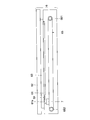
- FIGS. 2 and 3 are diagrams showing an example of the image reading unit 6 according to the embodiment.
- a document glass 61 (corresponding to a document table) is disposed on the upper right side of the image reading unit 6.
- the original glass 61 transmits light.
- the original is set on an original glass 61.
- the image reading unit 6 applies light to the document set on the document glass 61.
- the image processing unit 12 reads the lower side of the document to generate image data.
- the main control unit 1 stores the generated image data in the storage unit 2.
- a document pressing unit 62 is provided above the image reading unit 6.
- the document pressing unit 62 can be opened and closed.
- the document pressing unit 62 can be opened and closed so that the front side of the multifunction device 100 is swung up and down.
- FIG. 2 shows a state in which the document pressing unit 62 is closed.
- a document pressing plate 63 is attached to the lower surface of the document pressing unit 62.
- the document pressing plate 63 is, for example, a white plate.
- the document pressing plate 63 covers the document glass 61 from above.
- the document pressing plate 63 presses the document set on the document glass 61 from above.
- a document conveyance device may be attached instead of the document holding unit 62.
- the document transport unit also presses the document on the document glass 61.
- the document conveying device is a device for conveying a document which has been automatically set one by one.
- the image reading unit 6 is provided with a conveyance reading glass 61 a.
- the transport reading glass 61 a is provided on the left side of the original glass 61.
- the conveyed original passes over the conveyance reading glass 61a.
- the reading control unit 60 positions the reading unit 7 below the conveyance reading glass 61 a.
- the image reading unit 6 includes a reading control unit 60.
- the reading control unit 60 is a substrate that controls the operation of the image reading unit 6.
- the read control unit 60 includes a control circuit 60a, a memory 60b, and other circuits.
- the reading control unit 60 receives an instruction and a signal from the main control unit 1 and reads an original.
- the image reading unit 6 includes a reading unit 7, a white reference plate 64, a belt 65, a pulley 661, and a pulley 662.
- the reading unit 7 is a CIS scanning unit.
- the belt 65, the pulleys 661, and the pulleys 662 are mechanisms for moving the reading unit 7.
- the belt 65 is endless.
- Belt 65 is wound around each pulley.
- the belt 65 and the reading unit 7 are connected.
- a scanning motor 67 is provided in the image reading unit 6 (see FIG. 3).
- the scanning motor 67 rotates the pulley 662.
- the scanning motor 67 can rotate in forward and reverse directions.
- the reading control unit 60 rotates the scanning motor 67. Thereby, the belt 65 turns.
- the reading unit 7 moves in the horizontal direction (sub-scanning direction, right and left direction in FIG. 2).
- the reading control unit 60 moves the reading unit 7 in the sub-scanning direction.
- the white reference plate 64 is provided in the vicinity of the document glass 61 (left side in FIG. 2).
- the white reference plate 64 is provided at a position where the reading unit 7 can read.
- the reading unit 7 includes a lamp 71 and an image sensor 72.
- the reading unit 7 reads the document set on the document glass 61.
- a lamp 71 emits light to the document.
- the image sensor 72 includes a plurality of light receiving elements (pixels). The light receiving elements are arranged in the main scanning direction.
- the image sensor 72 is, for example, a line sensor.
- the light reflected by the document or document pressing plate 63 enters the light receiving element.
- Each light receiving element outputs an analog image signal according to the amount of light received (the amount of reflected light).
- the image reading unit 6 includes a data generation circuit unit 8. Based on the analog image signal output from the image sensor 72, the data generation circuit unit 8 generates image data.
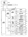
- FIG. 4 is a view showing an example of the reading control unit 60 and the data generation circuit unit 8 according to the embodiment.
- the read control unit 60 includes a plurality of devices.
- the read control unit 60 includes a control circuit 60a, a memory 60b, a PLL circuit 60c, and a start control circuit 60d.
- the data generation circuit unit 8 also includes a plurality of devices.
- the data generation circuit unit 8 includes, as devices, an amplification circuit 81, an offset circuit 82, an A / D conversion circuit 83, and a correction circuit 84.
- the control circuit 60 a is, for example, the CPU 11.
- the memory 60 b stores data for controlling the operation of the image reading unit 6 and a program.
- the control circuit 60a operates based on data and programs stored in the memory 60b.
- the PLL circuit 60c is a circuit that generates a signal of a preset frequency. For example, the PLL circuit 60c generates a clock signal for charge transfer of each light receiving element (image sensor 72). The clock signal generated by the PLL circuit 60 c is supplied to the image sensor 72. The PLL circuit 60 c may generate a clock signal for the synchronization signal of the image sensor 72. The PLL circuit 60c may generate a clock signal for operation of the control circuit 60a. The PLL circuit 60c may generate a clock signal for operating the memory 60b. The destination (device) of the signal generated by the PLL circuit 60c is predetermined.
- the start control circuit 60d controls the start of each device.
- power supply to the image reading unit 6 (reading control unit 60, data generation circuit unit 8) is started, activation of each device is started in a predetermined order.
- the order of power supply to each device is determined in advance.
- the start control circuit 60d is connected to all or part of the devices by a reset signal line.
- the start control circuit 60d releases the reset signal in a predetermined order. The device whose reset signal is released starts the boot process.
- the amplification circuit 81, the offset circuit 82, and the A / D conversion circuit 83 are parts (analog processing unit 80) that process an analog image signal of the image sensor 72.
- the analog processing unit 80 may be referred to as an AFE.
- the output of each light receiving element of the image sensor 72 is input to the amplification circuit 81.
- the amplification circuit 81 amplifies an analog image signal from each light receiving element.
- the amplifier circuit 81 stores the gain value 86.
- the amplification circuit 81 includes a memory (setting register) for storing the gain value 86.
- the read control unit 60 writes the gain value 86 into the memory.
- the reading control unit 60 sets a gain value 86 (details will be described later).
- the amplification circuit 81 amplifies the analog image signal with the set gain (amplification factor).
- the amplified analog image signal is input to the offset circuit 82.
- the offset circuit 82 adjusts the analog image signal by the output of each light receiving element of the image sensor 72 when the lamp 71 is turned off.
- the offset circuit 82 stores an offset value 87.
- the offset circuit 82 includes a memory (setting register) for storing the offset value 87.
- the reading control unit 60 sets an offset value 87 (details will be described later).
- the offset circuit 82 changes the analog image signal by the set offset value 87.
- the analog image signal adjusted by the offset circuit 82 is input to the A / D conversion circuit 83.
- the A / D conversion circuit 83 converts the input analog signal into a digital signal.
- the A / D conversion circuit 83 generates image data.
- the generated image data is input to the correction circuit 84. Due to the characteristics of the lamp 71, the image sensor 72, and the data generation circuit unit 8, distortion may occur in the image data.
- the correction circuit 84 is a circuit that corrects distortion of image data.
- the correction circuit 84 includes a shading correction circuit 85.
- the correction circuit 84 may include other types of correction circuits.
- the shading correction circuit 85 performs shading correction based on the reference value 88 determined for each light receiving element.
- the shading correction circuit 85 stores the reference value 88.
- the reference values 88 include white reference values and black reference values.
- the reading control unit 60 sets a reference value 88 (details will be described later).
- the shading correction circuit 85 includes a memory (register) for storing the reference value 88.
- the shading correction circuit 85 performs a shading correction operation based on the black reference value and the white reference value.
- the shading correction circuit 85 may perform shading correction using another arithmetic expression.
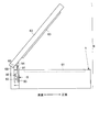
- FIG. 5 is a view showing an example of open / close detection of the document pressing unit 62 according to the embodiment.
- a support member 68 is provided on the back of the image reading unit 6.
- the document pressing unit 62 is attached to the support member 68.
- a rotating shaft 69 is provided at the upper end of the support member 68.
- the rotating shaft 69 is inserted at the end on the back side of the document pressing portion 62.
- the document pressing portion 62 can be rotated by swinging the front side up and down by the rotating shaft 69.
- the end on the front side of the multifunction device 100 of the document pressing unit 62 is a free end.
- the document pressing portion 62 can be open or closed with respect to the upper surface of the document glass 61.
- a document pressing plate 63 is provided as a part of the document pressing unit 62.
- the document pressing plate 63 covers the document glass 61.
- the document pressing plate 63 and the document glass 61 are in contact with each other.
- the document pressing plate 63 holds the document so as not to move.
- the open / close sensor 9 includes an abutment member 91, a transmission type light sensor 92, and a biasing member 93.
- the biasing member 93 biases the contact member 91 upward.
- the contact member 91 has the vertical direction as the longitudinal direction.
- the contact member 91 is a rod-like member. The position of the contact member 91 changes in the vertical direction according to the opening and closing of the document pressing unit 62. Due to the biasing of the biasing member 93, the contact member 91 is moved upward as the document pressing portion 62 is opened. Then, it protrudes from the upper surface of the image reading unit 6.
- the upper end portion 94 of the contact member 91 contacts the lower surface 2 e of the document pressing portion 62. Then, the contact member 91 is pushed downward as the document pressing portion 62 is closed (as it is turned over).
- a sensor interference unit 95 is provided below the contact member 91.
- the transmissive light sensor 92 detects that the contact member 91 (the sensor interference unit 95) has reached a predetermined position or less. In other words, the transmissive light sensor 92 detects that the document pressing unit 62 is closed more than a predetermined angle.
- the transmissive light sensor 92 includes a light emitting unit and a light receiving unit (not shown). The sensor interference unit 95 moves up and down between the light emitting unit and the light receiving unit. When the angle of the document pressing unit 62 becomes a predetermined angle, the output level of the light receiving unit changes.
- the predetermined angle is appropriately determined.
- the state in which the document pressing unit 62 is completely closed is assumed to be 0 degrees.
- the predetermined angle is, for example, any angle within the range of 15 degrees to 60 degrees.
- the position of the contact member 91 is set such that the output levels (High and Low) of the transmission type light sensor 92 change at a predetermined angle.
- the biasing member 93 biases the contact member 91 so that the output of the transmission type light sensor 92 changes at a predetermined angle.
- the open / close sensor 9 (transmission type light sensor 92) outputs the first level when the document pressing unit 62 is opened by a predetermined angle or more. When it is not opened more than the predetermined angle, the open / close sensor 9 outputs the second level. When the first level is high level, the second level is low level. When the first level is low level, the second level is high level.
- the output of the open / close sensor 9 is input to the reading control unit 60. Based on the output level of the open / close sensor 9, the reading control unit 60 recognizes whether the document pressing unit 62 is opened at a predetermined angle or more. In addition, when changing from the second level to the first level, the reading control unit 60 recognizes that the document pressing unit 62 has been opened by a predetermined angle or more. When the level changes from the first level to the second level, the reading control unit 60 recognizes that the document pressing unit 62 is closed below a predetermined angle.
- the reading control unit 60 instructs the reading unit 7 to read the document size detection. Let it go.
- the reading control unit 60 uses a change in the output level of the open / close sensor 9 as a trigger. In other words, when changing from the first level to the second level, the reading control unit 60 causes the reading unit 7 to read the document glass 61 before the document pressing unit 62 is completely closed.
- the reading control unit 60 moves the reading unit 7 from the home position to the document size detection position.
- the document size detection position is below the document glass 61.
- the document size detection position of the reading unit 7 is a position for reading a line separated by a predetermined distance from the left edge of the document glass 61 as viewed from above.
- the predetermined distance can be, for example, any value within the range of several millimeters to several centimeters.
- the home position of the reading unit 7 is predetermined.
- the home position may be below the white reference plate 64.
- a home position sensor is provided to detect that the reading unit 7 is at the home position.
- the reading control unit 60 After completion of reading, the reading control unit 60 returns the reading unit 7 to the home position.
- the reading control unit 60 stops the scanning motor 67.
- the reading control unit 60 includes a size detection unit 60e.
- the size detection unit 60e detects the size of the document in the main scanning direction.
- the size detection unit 60e may be provided as hardware (circuit). Further, the size detection unit 60e may be realized as software by the control circuit 60a or a program.
- the size detection unit 60e detects the size based on image data (hereinafter, referred to as “detection image data”) obtained by reading the left end portion of the document glass 61. In the reading before the document pressing unit 62 is completely closed, the light of the portion where the document does not exist is not reflected but leaks to the outside.
- the pixel value of the pixel in the portion where the document does not exist is darker than the pixel value of the pixel in the portion where the document exists.
- the size detection unit 60e compares the pixel value of each pixel in the detection image data with a predetermined threshold value. Based on the comparison, the size detection unit 60e determines the position of the boundary between the pixel range in which the document is read and the pixel range in which the portion without the document is read.
- the threshold is stored in a non-volatile manner in a storage device such as the memory 60 b.
- the size determination unit obtains the size (width) in the main scanning direction of the document. For example, the reading control unit 60 counts the number of pixels from the pixel corresponding to the position of the reference point to the boundary position. The pitch of one pixel is fixed in view of the reading resolution (if the resolution is 600 dpi, 25.4 [mm] ⁇ 600 ⁇ 42.3 [ ⁇ m] per pixel). Therefore, the reading control unit 60 multiplies the number of pixels from the pixel corresponding to the position of the reference point to the boundary position (the number of pixels in the main scanning direction) by the pitch of one pixel. Thus, the reading control unit 60 obtains the size of the document in the main scanning direction.
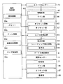
- FIG. 6 is a diagram illustrating an example of power supply in the multifunction peripheral 100 according to the embodiment.
- the multifunction peripheral 100 includes a power supply device 10.
- the power supply device 10 includes a primary power supply unit 10a, a secondary power supply unit 10b, and a power control unit 10c.
- the power supply cord C1 connects the commercial power supply 300 and the primary power supply unit 10a.
- the primary power supply unit 10a generates a DC voltage from the commercial power supply 300 (AC voltage).
- the primary power supply unit 10a generates a preset voltage. For example, the primary power supply unit 10 a generates DC 24 V for driving a motor.
- the multifunction peripheral 100 includes various circuits and elements.
- the types of voltage required for the operation of each circuit and each element also extend to a plurality of types.
- a plurality of types of voltages are required for operations of the main control unit 1, the storage unit 2, the operation panel 3, the printing unit 4, the communication unit 5, and the image reading unit 6. Therefore, the secondary power supply unit 10b generates a plurality of types of direct current voltages based on the generated voltage of the primary power supply unit 10a.
- the secondary power supply unit 10 b includes a plurality of power conversion circuits 10 d.
- the power conversion circuit 10d is a DC converter or a regulator.
- the magnitude of the output voltage of each power conversion circuit 10d is preset.
- the power supply control unit 10 c controls ON / OFF of each power conversion circuit 10 d.
- the secondary power supply unit 10 b generates and supplies a voltage having a magnitude necessary for operation.
- the secondary power supply unit 10b includes the main control unit 1 (CPU 11, image processing unit 12), storage unit 2, operation panel 3, printing unit 4, communication unit 5, image reading unit 6 (reading control unit 60, reading unit 7. Generate and supply a voltage of a magnitude necessary for the operation of the data generation circuit unit 8).
- the switch unit 10 e is provided so that the power supply can be stopped only at the portion where the supply is not performed.
- the switch unit 10 e is a switching element such as a transistor.
- a plurality of switch parts 10e are provided.
- the switch unit 10e is provided between the supply destination and the power conversion circuit 10d.
- the power control unit 10 c controls ON / OFF of each switch unit 10 e.
- the multifunction peripheral 100 has an active mode (normal mode) and a power saving mode.
- the power saving mode is a mode which reduces power consumption more than the active mode.
- the power saving mode may be referred to as a power saving mode, a power saving mode, or a sleep mode.
- the power supply device 10 stops the power supply to the predetermined supply stop portion.
- the supply stop part is decided suitably.
- the supply stop portion is the main control unit 1, the storage unit 2, a part of the operation panel 3, the printing unit 4, and a part of the image reading unit 6.
- the reading control unit 60, the reading unit 7, and the data generation circuit unit 8 are used as the supply stop portion.
- the main control unit 1 shifts the power supply device 10 to the power saving mode.
- Transition conditions are determined as appropriate.
- the operation to a specific hard key 33 (power saving key) provided on the operation panel 34 is a transition condition.
- the transition condition is that the time during which the operation panel 3 is not operated exceeds the predetermined transition time.
- the main control unit 1 gives the power supply device 10 a transition instruction.
- the power supply device 10 stops the power supply to the supply stop part.
- the main control unit 1 restores the power supply device 10 to the active mode.
- the release condition is determined as appropriate.
- the power supply device 10 resumes the power supply to the supply stop part.
- the power control unit 10 c supplies power to all parts of the multifunction peripheral 100.
- the power control unit 10 c is connected to the operation detection unit 101 via an interrupt signal line.
- the interrupt signal is input to the power control unit 10c.
- the power supply control unit 10c determines that the release condition is satisfied.
- the operation detection unit 101 is a unit that detects an operation or an input to the multifunction peripheral 100.
- the operation detection unit 101 is the communication unit 5.
- the communication unit 5 changes the level of the interrupt signal.
- the operation detection unit 101 may be the open / close sensor 9.
- the output of the open / close sensor 9 is input to the power control unit 10c.
- the power control unit 10c may determine that the release condition is satisfied.
- the operation detection unit 101 may be the operation panel 3.
- the operation panel 3 changes the level of the interrupt signal.
- the operation detection unit 101 is not limited to the above example. Other sensors or circuits may be used as the operation detection unit 101.
- the power supply device 10 supplies power to the operation detection unit 101 even in the power saving mode in order to determine the release condition.
- the operation detection unit 101 is excluded from the supply stop part.
- the open / close sensor 9 is excluded from the supply stop portion.
- FIG. 7 and FIG. 8 are diagrams showing an example of processing at the time of canceling the power saving mode in the MFP 100 according to the embodiment.
- the read control unit 60 determines a new adjustment value as one of the start processing. Then, the read control unit 60 sets the operation of the data generation circuit unit 8 with the determined adjustment value.
- the adjustment value includes a gain value 86, an offset value 87, and a reference value 88. It may take several seconds to set a new adjustment value and set the operation.
- the reading unit 7 performs reading a plurality of times (details will be described later). Therefore, while setting a new adjustment value and setting an operation, document size detection can not be performed.
- document size detection may need to be prioritized over acquisition of a new adjustment value.
- the user may operate the operation panel 3 to cancel the power saving mode. After operating the operation panel 3, the user may immediately set the document on the document glass 61 and close (downward) the document pressing unit 62. At this time, when the reading unit 7 is used for obtaining a new adjustment value when the document pressing unit 62 is closed below a predetermined angle, the document size can not be detected. Therefore, at the time of releasing the power saving mode, the reading control unit 60 appropriately determines whether or not the document size detection should be prioritized regardless of the reason (factor) for releasing the power saving mode.
- FIG. 7 is when the power saving mode is released.
- the common process is a predetermined process.
- the common process includes a process for stabilizing the read control unit 60, the data generation circuit unit 8, and the read unit 7 to enable operation.
- the common process can be said to be a preparation process for using the reading unit 7.
- the start control circuit 60d waits for a predetermined waiting time after resuming power supply to the image reading unit 6 (reading control unit 60, data generation circuit unit 8). This is to wait for stabilization of the power conversion circuit 10 d that supplies power to the image reading unit 6.
- the activation control circuit 60d performs, as a common process, a process of starting activation of devices in order.
- the start control circuit 60d releases the reset in a predetermined order. When the reset is released, the control circuit 60a, the memory 60b, the PLL circuit 60c, the circuit included in the data generation circuit unit 8, and the circuit included in the reading unit 7 start up.
- control circuit 60a communicates with the memory 60b, the PLL circuit 60c, the start control circuit 60d, the amplification circuit 81, the offset circuit 82, the A / D conversion circuit 83, and the correction circuit 84 (shading correction circuit 85). Establish. Further, as a common process, the control circuit 60a may confirm the presence or absence of an abnormality in the image sensor 72 and the lamp 71.
- the PLL circuit 60c performs processing of increasing the frequency of the clock signal to the set frequency (waiting for lock).
- the control circuit 60a performs a process of checking whether or not the phase lock in the PLL circuit 60c is completed.
- the predetermined common processing is eventually completed (step # 3). Then, the read control unit 60 checks whether the output level of the open / close sensor 9 is the first level (step # 4). In other words, the reading control unit 60 checks whether the document pressing unit 62 is opened by a predetermined angle or more.
- the reading control unit 60 determines to give priority to acquisition and setting of a new adjustment value (step # 5).
- the reading control unit 60 gives priority to obtaining a new adjustment value.
- the reading control unit 60 obtains a gain value 86, an offset value 87, a white reference value, and a black reference value as adjustment values.
- the reading control unit 60 may obtain values other than these as adjustment values.
- the reading control unit 60 moves the reading unit 7 below the white reference plate 64 (step # 6). Then, the reading control unit 60 turns on the lamp 71. The reading control unit 60 causes the reading unit 7 to read the white reference plate 64 (step # 7). Based on the reading result of the white reference board 64, the reading control unit 60 determines and sets the gain value 86 (step # 8). For example, the reading control unit 60 causes the maximum value of the analog image signal of each pixel obtained by reading the white reference plate 64 to coincide with the upper limit value of the conversion range (voltage range) of the A / D conversion circuit 83. Alternatively, the gain value 86 is set so as to be a value slightly smaller than the upper limit value. Then, the read control unit 60 writes the determined gain value 86 in the memory (register) of the amplification circuit 81. Thus, acquisition and setting of a new gain value 86 are completed.
- the reading control unit 60 turns off the lamp 71 and causes the reading unit 7 to output the reading result when the lamp 71 is turned off. (Step # 9). Based on the reading result when the lamp 71 is turned off, the reading control unit 60 obtains and sets the offset value 87 (step # 10). For example, the reading control unit 60 determines the offset value 87 such that the minimum value of the analog image signal of each pixel when the lamp 71 is turned off matches the lower limit value of the conversion range (voltage range) of the A / D conversion circuit 83. Then, the read control unit 60 writes the determined offset value 87 in the memory (register) of the offset circuit 82. Acquisition and setting of a new offset value 87 are completed.
- the reading control unit 60 lights the lamp 71, and the reading control unit 60 causes the reading unit 7 to read the white reference plate 64 (step # 11). Based on the reading result of the white reference plate 64, the reading control unit 60 acquires and sets the white reference value (step # 12). For example, the reading control unit 60 sets the digital value of the analog image signal of each pixel obtained by the reading of the white reference plate 64 as the white reference value. Then, the reading control unit 60 writes the determined white reference value in the memory (register) of the shading correction circuit 85. This completes the acquisition and setting of a new white reference value.
- the reading control unit 60 turns off the lamp 71 and causes the reading unit 7 to output the reading result when the lamp 71 is turned off. (Step # 13). Based on the reading result when the lamp 71 is turned off, the reading control unit 60 acquires and sets the black reference value (step # 14). For example, the reading control unit 60 sets the digital value of the analog image signal of each pixel when the lamp 71 is turned off as the black reference value. Then, the reading control unit 60 writes the determined black reference value in the memory (register) of the shading correction circuit 85. Acquisition and setting of new black reference values are complete.
- the read control unit 60 stores the newly determined adjustment value in the storage unit 2 (which may be the memory 60b) in a non-volatile manner (step # 15).
- the read control unit 60 causes the storage unit 2 to update each adjustment value.
- the reading control unit 60 rewrites the adjustment value of the storage unit 2. Then, the flow ends (end).
- step # 16 the reading control unit 60 determines to give priority to document size detection (step # 16).
- the reading control unit 60 gives priority to document size detection over acquisition of a new adjustment value.
- the read control unit 60 sets the gain value 86 stored in the storage unit 2 (step # 17). As described above, each time the gain value 86 is newly determined, the reading control unit 60 causes the storage unit 2 to update the gain value 86. When priority is given to document size detection, the gain value 86 stored in the storage unit 2 is the gain value 86 determined before the transition to the power saving mode.
- the read control unit 60 writes the previous gain value 86 into the memory of the amplifier circuit 81.
- the read control unit 60 sets the operation of the amplification circuit 81 using the previous gain value 86.
- the read control unit 60 sets the offset value 87 stored in the storage unit 2 (step # 18). As described above, each time the gain value 86 is newly determined, the reading control unit 60 causes the storage unit 2 to update the offset value 87. Therefore, when priority is given to document size detection, the offset value 87 stored in the storage unit 2 is the offset value 87 determined before the transition to the power saving mode.
- the read control unit 60 writes the previous offset value 87 into the memory of the offset circuit 82.
- the read control unit 60 sets the operation of the offset circuit 82 using the previous offset value 87.
- the reading control unit 60 sets the reference values 88 (white reference value, black reference value) stored in the storage unit 2 (step # 19). As described above, each time the reference value 88 is newly determined, the reading control unit 60 causes the storage unit 2 to update the reference value 88. Therefore, when priority is given to document size detection, the reference value 88 stored in the storage unit 2 is the reference value 88 determined before the transition to the power saving mode.
- the read control unit 60 writes the previous reference value 88 in the memory of the shading correction circuit 85.
- the reading control unit 60 sets the operation of the shading correction circuit 85 using the previous reference value 88.
- Each adjustment value may change before and after the transition to the power saving mode. However, since there is little dramatic change, it is possible to accurately detect the document size even using the previous adjustment value. Then, the read control unit 60 continues to check whether the output of the open / close sensor 9 has changed from the first level to the second level (step # 20, No in step # 20 ⁇ step # 20). As long as the document pressing unit 62 is open, the document pressing unit 62 is eventually closed. The reading control unit 60 waits for the document pressing unit 62 to close.
- the reading control unit 60 causes the reading unit 7 to read the document glass 61 (step # 21). . At this time, the reading control unit 60 operates the scanning motor 67. Then, the reading control unit 60 moves the reading unit 7 below the document glass 61.
- the reading control unit 60 detects the size of the document in the main scanning direction based on the image data obtained by reading (step # 22). Then, the flow moves to step # 5.
- the reading control unit 60 determines each adjustment value. Further, the reading control unit 60 sets each adjustment value.
- the image reading apparatus includes the document table (document glass 61), the reading control unit 60, the reading unit 7, the data generation circuit unit 8, the document pressing unit 62, the open / close sensor 9, the power supply device 10, A storage unit 2 is included.
- the reading unit 7 includes an image sensor 72 and reads an original set on an original table.
- the data generation circuit unit 8 generates image data based on the output of the image sensor 72.
- the document pressing unit 62 can be opened and closed, and presses the document table.
- the open / close sensor 9 outputs the first level when the document pressing unit 62 is opened by a predetermined angle or more.
- the open / close sensor 9 outputs the second level when it is not opened more than a predetermined angle.
- the power supply device 10 stops the power supply to the reading control unit 60 and the data generation circuit unit 8 in the power saving mode.
- the power supply device 10 supplies power to the reading control unit 60 and the data generation circuit unit 8 in the active mode.
- the storage unit 2 stores adjustment values for setting the operation of the data generation circuit unit 8.
- the reading control unit 60 performs a predetermined common process.
- the reading control unit 60 confirms the output of the open / close sensor 9 when the common processing is completed.
- the reading control unit 60 sets the operation of the data generation circuit unit 8 based on the adjustment value of the storage unit 2.
- the reading control unit 60 causes the reading unit 7 to perform reading for document size detection.
- the reading control unit 60 detects the size of the document based on the reading result.
- the common processing includes processing for stabilizing the devices included in the read control unit 60 and the data generation circuit unit 8 and enabling the devices.
- the reading control unit 60 instructs the reading unit 7 to newly set the adjustment value without detecting the size of the document.
- the operation of the data generation circuit unit 8 is set based on the newly determined adjustment value. If the document pressing unit 62 is closed at the completion of the common processing, there is a high possibility that the user does not set the document. When it is not necessary to give priority to document size detection, it is possible to give priority to acquisition of new adjustment values and setting of the data generation circuit unit 8.
- the reading control unit 60 detects the size of the document and then causes the reading unit 7 to perform reading for newly setting adjustment values.
- the operation of the data generation circuit unit 8 is set based on the newly determined adjustment value.
- the reading control unit 60 causes the reading unit 7 to read the document table, and the document is read based on the image data obtained by the reading. Detect the size in the main scanning direction. As a result, when the document pressing unit 62 is closed to a certain extent, reading for document size detection can be performed. This makes it easy to understand the boundary between the portion where the document is present and the portion where the document is not present. The size of the document can be detected accurately.
- the data generation circuit unit 8 includes an amplification circuit 81, an offset circuit 82, and a shading correction circuit 85.
- the read control unit 60 defines, as adjustment values, a gain value 86 used to set the amplification circuit 81, an offset value 87 used to set the offset circuit 82, and a reference value 88 used to set the shading correction circuit 85.
- the read control unit 60 stores the newly determined gain value 86, offset value 87, and reference value 88 in the storage unit 2 in a non-volatile manner.
- the amplifier circuit 81, the offset circuit 82, and the shading correction circuit 85 become available, it can be determined whether or not the first process is to be performed. Further, when priority is given to document size detection, document size detection can be performed without setting new gain values 86, offset values 87, and reference values 88. Further, the latest adjustment value can be stored in the storage unit 2.
- the read control unit 60 includes a control circuit 60a, a memory 60b, a PLL circuit 60c, and a start control circuit 60d.
- the start control circuit 60d sequentially performs reset cancellation as a common process, thereby controlling the control circuit 60a, the memory 60b, and the PLL circuit 60c, The start of the circuit included in the data generation circuit unit 8 is started.
- the control circuit 60a performs communication establishment with the memory 60b, the PLL circuit 60c, the start control circuit 60d, the amplification circuit 81, the offset circuit 82, the A / D conversion circuit 83, and the shading correction circuit 85 as common processing.
- the PLL circuit 60c performs processing to raise the frequency of the clock signal up to the set frequency as common processing. As described above, processing required for document size detection and setting of adjustment values can be common processing.
- the present invention is applicable to an image reading apparatus (image forming apparatus).
Landscapes
- Engineering & Computer Science (AREA)
- Multimedia (AREA)
- Signal Processing (AREA)
- Facsimile Scanning Arrangements (AREA)
- Facsimiles In General (AREA)
- Holders For Sensitive Materials And Originals (AREA)
Priority Applications (4)
| Application Number | Priority Date | Filing Date | Title |
|---|---|---|---|
| JP2019505085A JP6696623B2 (ja) | 2017-08-18 | 2018-06-13 | 画像読取装置、画像読取装置の制御方法 |
| EP18836586.0A EP3672214A4 (en) | 2017-08-18 | 2018-06-13 | IMAGE READER AND METHOD OF CONTROLLING THE IMAGE READER |
| CN201880003099.7A CN109691077B (zh) | 2017-08-18 | 2018-06-13 | 图像读取装置、图像读取装置的控制方法 |
| US16/323,891 US11277534B2 (en) | 2017-08-18 | 2018-06-13 | Image reading apparatus and method for controlling image reading apparatus |
Applications Claiming Priority (2)
| Application Number | Priority Date | Filing Date | Title |
|---|---|---|---|
| JP2017-157843 | 2017-08-18 | ||
| JP2017157843 | 2017-08-18 |
Publications (1)
| Publication Number | Publication Date |
|---|---|
| WO2019035272A1 true WO2019035272A1 (ja) | 2019-02-21 |
Family
ID=65362321
Family Applications (1)
| Application Number | Title | Priority Date | Filing Date |
|---|---|---|---|
| PCT/JP2018/022515 WO2019035272A1 (ja) | 2017-08-18 | 2018-06-13 | 画像読取装置、画像読取装置の制御方法 |
Country Status (5)
| Country | Link |
|---|---|
| US (1) | US11277534B2 (zh) |
| EP (1) | EP3672214A4 (zh) |
| JP (1) | JP6696623B2 (zh) |
| CN (1) | CN109691077B (zh) |
| WO (1) | WO2019035272A1 (zh) |
Families Citing this family (2)
| Publication number | Priority date | Publication date | Assignee | Title |
|---|---|---|---|---|
| WO2022025810A1 (en) * | 2020-07-29 | 2022-02-03 | Fingerprint Cards Anacatum Ip Ab | Adaptive readout from a global shutter optical biometric sensor |
| US11516413B2 (en) | 2020-07-29 | 2022-11-29 | Fingerprint Cards Anacatum Ip Ab | Adaptive readout from an optical biometric sensor to a host device |
Citations (4)
| Publication number | Priority date | Publication date | Assignee | Title |
|---|---|---|---|---|
| JPS6475025A (en) | 1987-09-18 | 1989-03-20 | Ryoko Sekkai Kogyo Kk | Humidity conditioning material |
| JP2010096937A (ja) * | 2008-10-16 | 2010-04-30 | Fuji Xerox Co Ltd | 制御回路、及び画像形成装置 |
| JP2015159351A (ja) * | 2014-02-21 | 2015-09-03 | 株式会社リコー | 画像読取装置、画像読取装置の制御方法及び制御プログラム |
| JP2016048840A (ja) * | 2014-08-27 | 2016-04-07 | 京セラドキュメントソリューションズ株式会社 | 画像読取装置及び画像形成装置 |
Family Cites Families (9)
| Publication number | Priority date | Publication date | Assignee | Title |
|---|---|---|---|---|
| JP3592046B2 (ja) | 1997-08-29 | 2004-11-24 | コニカミノルタホールディングス株式会社 | 画像読み取り装置 |
| JP2006238287A (ja) * | 2005-02-28 | 2006-09-07 | Ricoh Co Ltd | 原稿読取り装置および画像形成装置 |
| JP2006287901A (ja) * | 2005-03-10 | 2006-10-19 | Ricoh Co Ltd | 画像読取装置及び画像形成装置 |
| JP4841533B2 (ja) * | 2007-11-14 | 2011-12-21 | 理想科学工業株式会社 | 画像読取装置 |
| US20100321731A1 (en) * | 2009-06-19 | 2010-12-23 | Kabushiki Kaisha Toshiba | Image processing apparatus and method of controlling the image processing apparatus |
| JP6204240B2 (ja) * | 2014-03-27 | 2017-09-27 | 京セラドキュメントソリューションズ株式会社 | 電子機器、機器管理システム、および機器管理プログラム |
| JP6403001B2 (ja) * | 2014-11-17 | 2018-10-10 | 株式会社リコー | 画像形成システム |
| US10353652B2 (en) * | 2017-08-16 | 2019-07-16 | Xerox Corporation | Dynamic imposition identifier for items cut from sheets |
| US20190089860A1 (en) * | 2017-09-20 | 2019-03-21 | Kabushiki Kaisha Toshiba | Image processing device, image processing method, and non-transitory storage medium |
-
2018
- 2018-06-13 WO PCT/JP2018/022515 patent/WO2019035272A1/ja unknown
- 2018-06-13 CN CN201880003099.7A patent/CN109691077B/zh active Active
- 2018-06-13 EP EP18836586.0A patent/EP3672214A4/en active Pending
- 2018-06-13 US US16/323,891 patent/US11277534B2/en active Active
- 2018-06-13 JP JP2019505085A patent/JP6696623B2/ja active Active
Patent Citations (4)
| Publication number | Priority date | Publication date | Assignee | Title |
|---|---|---|---|---|
| JPS6475025A (en) | 1987-09-18 | 1989-03-20 | Ryoko Sekkai Kogyo Kk | Humidity conditioning material |
| JP2010096937A (ja) * | 2008-10-16 | 2010-04-30 | Fuji Xerox Co Ltd | 制御回路、及び画像形成装置 |
| JP2015159351A (ja) * | 2014-02-21 | 2015-09-03 | 株式会社リコー | 画像読取装置、画像読取装置の制御方法及び制御プログラム |
| JP2016048840A (ja) * | 2014-08-27 | 2016-04-07 | 京セラドキュメントソリューションズ株式会社 | 画像読取装置及び画像形成装置 |
Non-Patent Citations (1)
| Title |
|---|
| See also references of EP3672214A4 |
Also Published As
| Publication number | Publication date |
|---|---|
| US20210385345A1 (en) | 2021-12-09 |
| US11277534B2 (en) | 2022-03-15 |
| EP3672214A4 (en) | 2021-05-26 |
| CN109691077B (zh) | 2020-09-01 |
| JPWO2019035272A1 (ja) | 2019-11-07 |
| JP6696623B2 (ja) | 2020-05-20 |
| CN109691077A (zh) | 2019-04-26 |
| EP3672214A1 (en) | 2020-06-24 |
Similar Documents
| Publication | Publication Date | Title |
|---|---|---|
| JP5830837B2 (ja) | 画像読取装置および画像形成装置 | |
| JP6630511B2 (ja) | 画像読取装置 | |
| US8411336B2 (en) | Image reader, image forming device having the same, and computer-readable storage medium for the same | |
| US9094555B2 (en) | Reading device, image forming apparatus including the same, and control method for reading device | |
| JP2017085452A (ja) | 画像読取装置 | |
| JP6696623B2 (ja) | 画像読取装置、画像読取装置の制御方法 | |
| US9503605B2 (en) | Image reader, and method and computer-readable medium therefor | |
| JP5865861B2 (ja) | 画像読取装置および画像形成装置 | |
| US8526030B2 (en) | Image forming apparatus, power supplying method, and recording medium | |
| JP2014160936A (ja) | 原稿処理装置及び画像形成装置 | |
| JP2006013821A (ja) | 画像読み取り装置、画像データの補正方法 | |
| JP5171659B2 (ja) | 画像形成装置 | |
| JP2009111909A (ja) | 画像読取装置及び画像形成装置 | |
| JP6834912B2 (ja) | 画像読取装置 | |
| US10630860B2 (en) | Image reading device and method for controlling image reading device | |
| JP2015138249A (ja) | 画像形成装置 | |
| JP2005123681A (ja) | 画像読み取り装置 | |
| JP2006080941A (ja) | 画像読み取り装置 | |
| JP6287694B2 (ja) | 画像読取装置及び画像読取方法 | |
| JP2010021946A (ja) | 原稿読取装置及び画像形成装置 | |
| JP3930508B2 (ja) | 画像読取装置 | |
| JP5096996B2 (ja) | 画像形成装置 | |
| JP2014209678A (ja) | 画像読取装置及びこれを備えた画像形成装置 | |
| JP2017118436A (ja) | 画像読取装置 | |
| JP2008278278A (ja) | 画像読取装置 |
Legal Events
| Date | Code | Title | Description |
|---|---|---|---|
| ENP | Entry into the national phase |
Ref document number: 2019505085 Country of ref document: JP Kind code of ref document: A |
|
| 121 | Ep: the epo has been informed by wipo that ep was designated in this application |
Ref document number: 18836586 Country of ref document: EP Kind code of ref document: A1 |
|
| NENP | Non-entry into the national phase |
Ref country code: DE |
|
| ENP | Entry into the national phase |
Ref document number: 2018836586 Country of ref document: EP Effective date: 20200318 |