WO2019031443A1 - 立体表示装置 - Google Patents
立体表示装置 Download PDFInfo
- Publication number
- WO2019031443A1 WO2019031443A1 PCT/JP2018/029388 JP2018029388W WO2019031443A1 WO 2019031443 A1 WO2019031443 A1 WO 2019031443A1 JP 2018029388 W JP2018029388 W JP 2018029388W WO 2019031443 A1 WO2019031443 A1 WO 2019031443A1
- Authority
- WO
- WIPO (PCT)
- Prior art keywords
- light
- pixel
- display device
- refracting
- lenticular
- Prior art date
- Legal status (The legal status is an assumption and is not a legal conclusion. Google has not performed a legal analysis and makes no representation as to the accuracy of the status listed.)
- Ceased
Links
Images


Classifications
-
- G—PHYSICS
- G02—OPTICS
- G02B—OPTICAL ELEMENTS, SYSTEMS OR APPARATUS
- G02B27/00—Optical systems or apparatus not provided for by any of the groups G02B1/00 - G02B26/00, G02B30/00
- G02B27/01—Head-up displays
- G02B27/0101—Head-up displays characterised by optical features
-
- B—PERFORMING OPERATIONS; TRANSPORTING
- B60—VEHICLES IN GENERAL
- B60K—ARRANGEMENT OR MOUNTING OF PROPULSION UNITS OR OF TRANSMISSIONS IN VEHICLES; ARRANGEMENT OR MOUNTING OF PLURAL DIVERSE PRIME-MOVERS IN VEHICLES; AUXILIARY DRIVES FOR VEHICLES; INSTRUMENTATION OR DASHBOARDS FOR VEHICLES; ARRANGEMENTS IN CONNECTION WITH COOLING, AIR INTAKE, GAS EXHAUST OR FUEL SUPPLY OF PROPULSION UNITS IN VEHICLES
- B60K35/00—Instruments specially adapted for vehicles; Arrangement of instruments in or on vehicles
- B60K35/20—Output arrangements, i.e. from vehicle to user, associated with vehicle functions or specially adapted therefor
- B60K35/21—Output arrangements, i.e. from vehicle to user, associated with vehicle functions or specially adapted therefor using visual output, e.g. blinking lights or matrix displays
- B60K35/211—Output arrangements, i.e. from vehicle to user, associated with vehicle functions or specially adapted therefor using visual output, e.g. blinking lights or matrix displays producing three-dimensional [3D] effects, e.g. stereoscopic images
-
- B—PERFORMING OPERATIONS; TRANSPORTING
- B60—VEHICLES IN GENERAL
- B60K—ARRANGEMENT OR MOUNTING OF PROPULSION UNITS OR OF TRANSMISSIONS IN VEHICLES; ARRANGEMENT OR MOUNTING OF PLURAL DIVERSE PRIME-MOVERS IN VEHICLES; AUXILIARY DRIVES FOR VEHICLES; INSTRUMENTATION OR DASHBOARDS FOR VEHICLES; ARRANGEMENTS IN CONNECTION WITH COOLING, AIR INTAKE, GAS EXHAUST OR FUEL SUPPLY OF PROPULSION UNITS IN VEHICLES
- B60K35/00—Instruments specially adapted for vehicles; Arrangement of instruments in or on vehicles
- B60K35/20—Output arrangements, i.e. from vehicle to user, associated with vehicle functions or specially adapted therefor
- B60K35/21—Output arrangements, i.e. from vehicle to user, associated with vehicle functions or specially adapted therefor using visual output, e.g. blinking lights or matrix displays
- B60K35/23—Head-up displays [HUD]
-
- G—PHYSICS
- G02—OPTICS
- G02B—OPTICAL ELEMENTS, SYSTEMS OR APPARATUS
- G02B30/00—Optical systems or apparatus for producing three-dimensional [3D] effects, e.g. stereoscopic images
- G02B30/10—Optical systems or apparatus for producing three-dimensional [3D] effects, e.g. stereoscopic images using integral imaging methods
-
- G—PHYSICS
- G02—OPTICS
- G02B—OPTICAL ELEMENTS, SYSTEMS OR APPARATUS
- G02B30/00—Optical systems or apparatus for producing three-dimensional [3D] effects, e.g. stereoscopic images
- G02B30/20—Optical systems or apparatus for producing three-dimensional [3D] effects, e.g. stereoscopic images by providing first and second parallax images to an observer's left and right eyes
- G02B30/26—Optical systems or apparatus for producing three-dimensional [3D] effects, e.g. stereoscopic images by providing first and second parallax images to an observer's left and right eyes of the autostereoscopic type
- G02B30/27—Optical systems or apparatus for producing three-dimensional [3D] effects, e.g. stereoscopic images by providing first and second parallax images to an observer's left and right eyes of the autostereoscopic type involving lenticular arrays
- G02B30/29—Optical systems or apparatus for producing three-dimensional [3D] effects, e.g. stereoscopic images by providing first and second parallax images to an observer's left and right eyes of the autostereoscopic type involving lenticular arrays characterised by the geometry of the lenticular array, e.g. slanted arrays, irregular arrays or arrays of varying shape or size
-
- G—PHYSICS
- G03—PHOTOGRAPHY; CINEMATOGRAPHY; ANALOGOUS TECHNIQUES USING WAVES OTHER THAN OPTICAL WAVES; ELECTROGRAPHY; HOLOGRAPHY
- G03B—APPARATUS OR ARRANGEMENTS FOR TAKING PHOTOGRAPHS OR FOR PROJECTING OR VIEWING THEM; APPARATUS OR ARRANGEMENTS EMPLOYING ANALOGOUS TECHNIQUES USING WAVES OTHER THAN OPTICAL WAVES; ACCESSORIES THEREFOR
- G03B35/00—Stereoscopic photography
- G03B35/18—Stereoscopic photography by simultaneous viewing
- G03B35/24—Stereoscopic photography by simultaneous viewing using apertured or refractive resolving means on screens or between screen and eye
-
- H—ELECTRICITY
- H04—ELECTRIC COMMUNICATION TECHNIQUE
- H04N—PICTORIAL COMMUNICATION, e.g. TELEVISION
- H04N13/00—Stereoscopic video systems; Multi-view video systems; Details thereof
- H04N13/30—Image reproducers
-
- H—ELECTRICITY
- H04—ELECTRIC COMMUNICATION TECHNIQUE
- H04N—PICTORIAL COMMUNICATION, e.g. TELEVISION
- H04N13/00—Stereoscopic video systems; Multi-view video systems; Details thereof
- H04N13/30—Image reproducers
- H04N13/302—Image reproducers for viewing without the aid of special glasses, i.e. using autostereoscopic displays
- H04N13/305—Image reproducers for viewing without the aid of special glasses, i.e. using autostereoscopic displays using lenticular lenses, e.g. arrangements of cylindrical lenses
-
- H—ELECTRICITY
- H04—ELECTRIC COMMUNICATION TECHNIQUE
- H04N—PICTORIAL COMMUNICATION, e.g. TELEVISION
- H04N13/00—Stereoscopic video systems; Multi-view video systems; Details thereof
- H04N13/30—Image reproducers
- H04N13/324—Colour aspects
-
- H—ELECTRICITY
- H04—ELECTRIC COMMUNICATION TECHNIQUE
- H04N—PICTORIAL COMMUNICATION, e.g. TELEVISION
- H04N13/00—Stereoscopic video systems; Multi-view video systems; Details thereof
- H04N13/30—Image reproducers
- H04N13/346—Image reproducers using prisms or semi-transparent mirrors
-
- H—ELECTRICITY
- H04—ELECTRIC COMMUNICATION TECHNIQUE
- H04N—PICTORIAL COMMUNICATION, e.g. TELEVISION
- H04N13/00—Stereoscopic video systems; Multi-view video systems; Details thereof
- H04N13/30—Image reproducers
- H04N13/363—Image reproducers using image projection screens
-
- G—PHYSICS
- G02—OPTICS
- G02B—OPTICAL ELEMENTS, SYSTEMS OR APPARATUS
- G02B27/00—Optical systems or apparatus not provided for by any of the groups G02B1/00 - G02B26/00, G02B30/00
- G02B27/01—Head-up displays
- G02B27/0101—Head-up displays characterised by optical features
- G02B2027/0112—Head-up displays characterised by optical features comprising device for genereting colour display
-
- G—PHYSICS
- G02—OPTICS
- G02B—OPTICAL ELEMENTS, SYSTEMS OR APPARATUS
- G02B27/00—Optical systems or apparatus not provided for by any of the groups G02B1/00 - G02B26/00, G02B30/00
- G02B27/01—Head-up displays
- G02B27/0101—Head-up displays characterised by optical features
- G02B2027/0118—Head-up displays characterised by optical features comprising devices for improving the contrast of the display / brillance control visibility
-
- G—PHYSICS
- G02—OPTICS
- G02B—OPTICAL ELEMENTS, SYSTEMS OR APPARATUS
- G02B27/00—Optical systems or apparatus not provided for by any of the groups G02B1/00 - G02B26/00, G02B30/00
- G02B27/01—Head-up displays
- G02B27/0101—Head-up displays characterised by optical features
- G02B2027/0132—Head-up displays characterised by optical features comprising binocular systems
- G02B2027/0134—Head-up displays characterised by optical features comprising binocular systems of stereoscopic type
-
- G—PHYSICS
- G02—OPTICS
- G02B—OPTICAL ELEMENTS, SYSTEMS OR APPARATUS
- G02B27/00—Optical systems or apparatus not provided for by any of the groups G02B1/00 - G02B26/00, G02B30/00
- G02B27/01—Head-up displays
- G02B27/0101—Head-up displays characterised by optical features
- G02B2027/0132—Head-up displays characterised by optical features comprising binocular systems
- G02B2027/0136—Head-up displays characterised by optical features comprising binocular systems with a single image source for both eyes
Definitions
- the present disclosure relates to a stereoscopic display used in a head-up display.
- Patent Document 1 proposes a configuration in which a lenticular lens for refracting light is provided for each pixel in the above-described three-dimensional display device.
- a three-dimensional display device includes an image display unit, one or more color-forming refracting units, and a viewpoint refracting unit.
- the image display unit is configured to display one set or a plurality of sets of parallax images using a plurality of color forming portions arranged in the vertical direction and the horizontal direction, with the plurality of color forming portions as pixel elements for one pixel. Ru.
- the color forming refracting portion is configured to transmit light emitted through the plurality of color forming portions and to diverge or collect light at an angle set in advance for each color forming portion.
- the viewpoint refracting portion is configured to refract the light directed to each viewpoint while transmitting the light transmitted through the color forming refracting portion.
- each color forming portion is provided with a color forming refracting portion for refracting light, a point image reflecting color and luminance information of each color forming portion is formed in the vicinity of the focal length of the color forming refracting portion.
- the aperture ratio is reduced in a pseudo manner. Therefore, it is possible to suppress crosstalk in which light to a certain viewpoint is mixed with light to another viewpoint.
- the aperture ratio represents the ratio of the opening to the entire area when the area on the viewpoint side of each color forming portion is the entire area and part of the entire area is shielded and the remaining part is the opening.
- the reference numerals in parentheses described in the claims indicate the correspondence with specific means described in the embodiment described later as one aspect, and the technical scope of the present disclosure is not limited. Absent.
- a head-up display 1 which is an example of the present disclosure is, as shown in FIG. 1, mounted on a movable body such as a vehicle AM and used, and has a function of providing a stereoscopic image.
- the head-up display 1 includes a stereoscopic display 10.
- the head-up display 1 may also include a control circuit 50.
- the stereoscopic display device 10 is a device that has two or more viewpoints at a certain distance from the display device and can provide parallax images according to the viewpoints.
- the parallax image is a perspective projection of a three-dimensional display object to be displayed on a two-dimensional image from a viewpoint position at which the three-dimensional object is set.
- the stereoscopic display device 10 emits a light beam based on an image toward the windshield G which is a projection target member. This light beam is reflected by the windshield G and directed to the driver's gaze, i.e., the eye range ER. Then, in the eye range ER, a virtual image VI is formed in front of the vehicle AM to make the driver visually recognize.
- the various information displayed as the virtual image VI includes vehicle information and foreground information.
- vehicle information includes, for example, numerical information indicating a traveling state of the vehicle AM, specifically, information such as a vehicle speed, an engine speed, and a fuel remaining amount.
- foreground information includes information that supplements the foreground that the driver visually recognizes through the windshield G, specifically, information on the position and traveling direction of a pedestrian or another vehicle, a route to be traveled, and the like.
- an optical axis B in FIG. 1 is a schematic view showing, for example, a part such as a center of an optical path of light displayed by the stereoscopic display device 10.
- the control circuit 50 sends control signals for controlling the light source 11 of the stereoscopic display device 10 and the liquid crystal panel 21 shown in FIG. Specifically, the control circuit 50 performs control to specify the brightness of the light source 11 and the type of the image to be displayed by the liquid crystal panel 21 in accordance with a command input by a known sensor or driver of the vehicle AM. A signal is generated and this control signal is sent to the stereoscopic display 10.
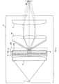
- the stereoscopic display device 10 includes an image generation unit 20A, a stereoscopic viewing lenticular 16, and a projection lens 17.
- the stereoscopic display 10 may include a light source 11 and an illumination lens 12.
- the image generation unit 20A includes an image display unit 22 and a light shielding diffusion plate 24.
- the image display unit 22 includes a liquid crystal panel 21 and a sub-pixel MLA 23.
- MLA is an abbreviation of microlens array.
- the image generation unit 20A corresponds to the super multi-view stereo display.
- the super multi-view method represents a method of displaying a plurality of sets of parallax images at an interval equal to or less than the pupil diameter of a person.
- ordinary multi-view methods induce convergence and binocular parallax and motion parallax as functions of distance perception
- super-multi-view methods can also induce adjustment functions.
- Super multi-view method see, for example, Japanese Patent Application Laid-Open No. 2012-18245 and the article "Y. Takaki, Y. Urano, S. Kashiwada, H. Ando, and K. Nakamura," Super multi-view windshield display for long-distance
- the technology described in, for example, image information presentation, "Opt. Express 19, 704-716 (2011)" can be used.
- the configuration of this embodiment corresponds to the display in the super multi-view method
- the present disclosure can also cope with other multi-view methods such as ordinary multi-view method and integral imaging which are not super multi-view. .
- the liquid crystal panel 21, the sub-pixel MLA 23, and the light shielding diffusion plate 24 are each formed in a plate shape.
- the stereoscopic lenticular 16 and the projection lens 17 are configured to refract the light emitted from the image generation unit 20A toward each viewpoint while transmitting the light.
- the stereoscopic lenticular lens 16 is configured as a known lenticular lens
- the projection lens 17 is configured as a known convex lens or a concave lens. The curvature and the refractive index of these lenses are set so that the image generated by the stereoscopic display device 10 can be well imaged by the eye range ER.
- the stereoscopic lens 16 and the projection lens 17 are configured by dividing the viewpoint and forming the viewpoint and the function to the eye range ER, respectively, but the pitch of the stereoscopic use lenticular 16 is changed May be integrated and configured.
- a Fresnel lens or a diffractive optical element can be used for the projection lens 17 in order to reduce the thickness. More preferably, an optical element having a free curved surface shape for correcting an aberration generated due to the shape of the window shield or a diffractive optical element having phase information corresponding to the free curved surface shape may be used.
- the light source 11 emits light serving as a backlight of the liquid crystal panel 21 according to a control signal from the control circuit 50 as shown in FIG. 2 and supplies the light to the liquid crystal panel 21 through the illumination lens 12. .
- the illumination lens 12 is configured as a known convex lens that refracts light emitted by the light source 11 into parallel light.
- a Fresnel lens or a diffractive optical element may be used as the illumination lens 12 for thinning.
- any lighting device such as an LED or a laser device can be used.
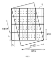
- the liquid crystal panel 21 has a plurality of coloring portions 21R, 21G in which a plurality of coloring portions 21R, 21G, 21B are arranged in vertical and horizontal directions as pixel elements for one pixel. , 21B.
- the liquid crystal panel 21 is configured to display a plurality of sets of parallax images by controlling the amount of light passing through each of the color developing units 21R, 21G, and 21B according to a control signal from the control circuit 50. .
- the liquid crystal panel 21 is configured to transmit light from the light source 11, and the plurality of color forming portions 21R, 21G, 21B arrange the color forming portions 21R, 21G, 21B of different colors in the longitudinal direction and the lateral direction. Constitute a pixel element.
- the vertical direction is a direction corresponding to the vertical direction, it is not a direction coincident with the vertical direction but a direction having a predetermined angle with the vertical direction. is there.
- the horizontal direction is a direction orthogonal to the vertical direction, and is a direction having a small angle set in advance in the horizontal direction.
- the color developing units 21R, 21G, and 21B in which the same numbers are described among the color developing units 21R, 21G, and 21B correspond to the same parallax image. That is, three color development parts 21R, 21G, and 21B of R, G, and B arranged in the perpendicular direction constitute one pixel.
- the resolution in the horizontal direction can be increased compared to a normal liquid crystal panel in which the vertical direction matches the vertical direction. .
- the resolution in the horizontal direction it is possible to easily secure the resolution in the horizontal direction.
- the liquid crystal panel 21 is configured such that a region on the side of the color forming portions 21R, 21G, and 21B on the stereoscopic viewing lenticular 16 side is the entire region, a part of the entire region is shielded, and the remaining portion is the opening portion. .
- the ratio of the opening to the entire area is taken as the opening ratio.
- the aperture ratio is appropriately set so that crosstalk does not easily occur.
- the light shielding diffusion plate 24 includes a pinhole array plate 25 and a horizontal diffusion plate 26.
- the pinhole array plate 25 and the horizontal diffusion plate 26 are each formed in a plate shape.
- the subpixel MLA 23 and the horizontal diffusion plate 26 condense the light at an angle set in advance for each of the coloring portions 21R, 21G, 21B while transmitting the light emitted through the plurality of coloring portions 21R, 21G, 21B. Or configured to diverge.
- the arrows shown in FIG. 4, FIG. 8 and FIG. 11 to FIG. 20 indicate the traveling direction of the light emitted by the light source 11.
- the sub-pixel MLA 23 is configured as a micro-lens array in which a large number of micro-lenses that refract light for each of the coloring portions 21R, 21G, and 21B are arrayed in a matrix.
- Each microlens is configured as a convex lens that collects light in the vertical direction and the horizontal direction.
- the microlenses are set to have the same refractive index in the vertical direction and in the horizontal direction.
- the microlens may be configured by an aspheric lens, a diffractive optical element, or a holographic optical element.
- the horizontal diffusion plate 26 has a function of refracting light having passed through the sub-pixel MLA 23 so as to diffuse only in the horizontal direction.
- a holographic element or a lenticular lens can be adopted.
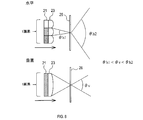
- the pinhole array plate 25 is disposed closer to the focal position F by the sub-pixel MLA 23 than the sub-pixel MLA 23 as shown in FIG. 4 and FIG. It has a hole 25H.
- the large number of holes 25H are formed for each of the micro lenses forming the sub-pixel MLA 23, and are set to a size that can block most of the light other than the light collected by the sub-pixel MLA 23.
- the image formed by the sub-pixel MLA 23 be smaller than the size of the sub-pixel, that is, each of the color developing portions 21R, 21G, and 21B in order to suppress crosstalk.
- the lateral length of the color forming portions 21R, 21G, 21B is x
- the length in the vertical direction is y
- the arrangement interval of the color forming portions 21R, 21G, 21B As the conditions for this, as shown in FIG. 6, the lateral length of the color forming portions 21R, 21G, 21B is x
- the length in the vertical direction is y
- the arrangement interval of the color forming portions 21R, 21G, 21B As the conditions for this, as shown in FIG. 6, the lateral length of the color forming portions 21R, 21G, 21B is x
- the length in the vertical direction is y
- the arrangement interval of the color forming portions 21R, 21G, 21B Assuming that the pitch is p x , p y , the lateral size of the light source is d sx , the longitudinal size is d sy , the focal length of the illumination lens 12 is f IL , and the focal length of the sub-pixel MLA 23 is f M
- the pitch of the stereoscopic lens 16 is P L
- the angle of the lenticular lens is ⁇
- the number of viewpoints set in the super multi-view method is N
- d sx x f MLA / f IL x cos ⁇ + d sy x f MLA / f IL x sin ⁇ ⁇ P L / N It is sufficient to satisfy the
- the angle ⁇ of the lenticular lens represents an angle difference between the horizontal direction and the horizontal direction shown in FIG.
- the length obtained by projecting the image formed by the sub-pixel MLA 23 in the pitch direction of the stereoscopic lens 16 is the number obtained by dividing the pitch of the lenticular lens 16 by the number of viewpoints, that is, one viewpoint. Because the projection length is smaller than this, crosstalk can be further reduced.
- the head-up display 1 of the present disclosure includes the liquid crystal panel 21, the sub-pixel MLA 23, the horizontal diffusion plate 26, the stereoscopic lenticular 16, and the projection lens 17.
- the liquid crystal panel 21 uses a plurality of color forming portions 21R, 21G, 21B arranged in the vertical direction and the horizontal direction as pixel elements of a plurality of color forming portions 21R, 21G, 21B for one set or plural sets. Are configured to display parallax images of
- the sub-pixel MLA 23 and the horizontal diffusion plate 26 refract light emitted in the directions set in advance for each of the color forming portions 21R, 21G, 21B while transmitting light emitted through the plurality of color forming portions 21R, 21G, 21B. Configured as.
- the stereoscopic vision lenticular 16 and the projection lens 17 are configured to refract light toward each viewpoint while transmitting light transmitted through the sub-pixel MLA 23 and the horizontal diffusion plate 26.
- the head-up display 1 since the sub-pixel MLA 23 and the horizontal diffusion plate 26 that refract light are provided for each of the coloring portions 21R, 21G, 21B, the coloring portions 21R, 21G, A point image group having information for each 21B can be formed.
- the point image group since the size of the point image is sufficiently reduced by illuminating the liquid crystal panel 21 with substantially parallel light, the point image group can be regarded as the liquid crystal panel 21 with a reduced aperture ratio. Since the aperture ratio of the point image group does not increase even if the aperture ratio of the liquid crystal panel 21 is increased, crosstalk can be reduced while enhancing the brightness of the image. Therefore, the brightness of the image generated by the head-up display 1 can be increased.
- the sub-pixel MLA 23 is configured to refract light in at least one of the vertical direction and the horizontal direction, and the horizontal diffusion plate 26 refracts light only in the horizontal direction. Configured as.
- the horizontal diffusion plate 26 refracts light only in the horizontal direction, the width of the viewing area, that is, the horizontal length of the eye range can be easily adjusted. .
- the sub-pixel MLA 23 is configured as a micro-lens array in which micro lenses for refracting light are arrayed and arranged for each of the color forming portions 21R, 21G, 21B.
- the horizontal diffusion plate 26 is configured to diffuse the light passing through the sub-pixel MLA 23 only in the horizontal direction.
- the head-up display 1 can be configured with a member having a substantially flat appearance in comparison with the configuration provided with a plurality of lenticular lenses, so the assembly of the head-up display 1 is facilitated. It can be carried out. More specifically, when the image generation unit 20A is configured to include a plurality of lenticular lenses, it is necessary to adjust the positions and angles of the liquid crystal panel and the plurality of lenticular lenses with respect to each other. However, in the configuration of the present embodiment provided with the sub-pixel MLA 23 and the horizontal diffusion plate 25, the liquid crystal panel 21 and the sub-pixel MLA 23 only need to adjust the position and angle of each other, and the horizontal diffusion plate only performs the angle adjustment. As it should be done, assembly becomes easy.
- the above-described head-up display 1 further includes a pinhole array plate 25.
- the pinhole array plate 25 is disposed closer to the focal position F of the sub-pixel MLA 23 than the sub-pixel MLA 23 and has a large number of holes 25 H for passing light collected by the sub-pixel MLA 23.
- the pinhole array plate 25 blocks scattered light and the like other than the light collected by the sub-pixel MLA 23, crosstalk can be further suppressed.
- the pinhole array plate 25 is disclosed only in this embodiment, but can be applied to the configurations of the following embodiments.
- the above-described head-up display 1 further includes a light source 11 and an illumination lens 12 configured to supply parallel light to the plurality of color developing units 21R, 21G, and 21B. According to such a head-up display 1, it is possible to reduce divergent light due to diffraction in the image generation unit 20A.
- the head-up display 1 includes the image generation unit 20A including the sub-pixel MLA 23 and the horizontal diffusion plate 26.
- the head-up display 2 of the second embodiment is different from the first embodiment in that an image generating unit 20B having pixel lenticulars 31B and sub-pixel lenticulars 32B is provided instead of the image generating unit 20A.
- the stereoscopic display device 10 includes an image generation unit 20B.
- the image generation unit 20B includes, in addition to the liquid crystal panel 21 described above, a pixel lenticular 31B and a subpixel lenticular 32B.
- the pixel lenticule 31 B and the sub-pixel lenticule 32 B are disposed so as to overlap the stereoscopic vision lenticule 16 of the liquid crystal panel 21 and the projection lens 17 side.
- the liquid crystal panel 21, the pixel lenticular 31B, and the sub-pixel lenticular 32B are stacked in this order.
- the pixel lenticular 31B and the sub-pixel lenticular 32B are respectively convex lenses and configured as well-known lenticular lenses.
- the lenticular lens is configured by arranging a plurality of semi-cylindrical lenses at a predetermined pitch, and has a lens portion having a predetermined curvature radius and a flat portion having a substantially flat plate shape on the opposite side of the lens portion. , Is a transparent structure having a predetermined thickness.
- the lenticular lens is made of, for example, glass or resin.
- the pixel lenticular 31B has a configuration in which semi-cylindrical lenses having a width that matches the arrangement interval of the coloring portions 21R, 21G, and 21B in the vertical direction are arranged in the vertical direction.
- the subpixel lenticular 32B is configured by arranging in the horizontal direction semi-cylindrical lenses having a width that matches the arrangement interval of the coloring portions 21R, 21G, and 21B in the horizontal direction.
- the sub-pixel lenticular 32B refracts light for each of the coloring portions 21R, 21G, and 21B.
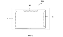
- the stereoscopic display 10 includes a spacer 41 between the pixel lenticule 31B and the sub-pixel lenticule 32B, as shown in FIG. 10, FIG. 11 and FIG.
- prismatic members having the same thickness are arranged at the upper end, the right end, and the left end of the pixel lenticular 31B and the sub-pixel lenticular 32B, and the distance between the pixel lenticular 31B and the subpixel lenticular 32B is constant. Hold these.
- the focal position F ie, the imaging position by the pixel lenticular 31B and the sub-pixel lenticular 32B held in this manner is configured to be located on the same plane orthogonal to the optical axis of the pixel lenticular 31B and the sub-pixel lenticular 32B. .
- the focal position F in this embodiment is closer to the stereoscopic lenticular 16 than the subpixel lenticular 32B, when the pinhole array plate 25 shown in the first embodiment is disposed, the stereoscopic position of the subpixel lenticular 32B is determined. It is preferable to dispose on the viewing lenticular 16 side.
- the image formed by the sub-pixel lenticular 32B is smaller than the size of the sub-pixels, that is, the individual color developing portions 21R, 21G, and 21B in the same manner as in the first embodiment for suppressing crosstalk. Is preferred.
- the plurality of color forming portions 21R, 21G, and 21B form pixel elements by arranging the color forming portions 21R, 21G, and 21B of different colors in the lateral direction.
- the pixel lenticular 31B and the subpixel lenticular 32B are provided.
- the pixel lenticular 31B is configured by arranging in the vertical direction semi-cylindrical lenses having a width that matches the arrangement interval of the coloring portions 21R, 21G, and 21B in the vertical direction.
- the subpixel lenticular 32B is configured by arranging in the horizontal direction semi-cylindrical lenses having a width that matches the arrangement interval of the coloring portions 21R, 21G, and 21B in the horizontal direction.
- light is refracted in the vertical direction and the horizontal direction by using a plurality of lenticular lenses that refract light in directions orthogonal to each other. It can be diffused.
- the pixel lenticular 31B and the sub-pixel lenticular 32B are disposed so as to overlap the stereoscopic viewing lenticular 16 and the projection lens 17 side of the liquid crystal panel 21.
- the focal position F by the pixel lenticular 31B and the subpixel lenticular 32B is configured to be located on the same plane orthogonal to the optical axis of the pixel lenticular 31B and the subpixel lenticular 32B. .
- the head-up display 2 according to the second embodiment described above includes the image generation unit 20B having the pixel lenticular 31B and the sub-pixel lenticular 32B, which are convex lenses, respectively.
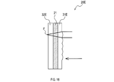
- the head-up display 3 according to the third embodiment is different from the head-up display 3 according to the second embodiment in that an image generation unit 20C having a pixel lenticular 31C formed of a concave lens is provided.
- the stereoscopic display device 10 includes an image generation unit 20C.
- the image generation unit 20C includes a pixel lenticular 31C and a sub-pixel lenticular 32C in addition to the liquid crystal panel 21 described above.
- the pixel lenticule 31 C and the sub-pixel lenticule 32 C are disposed so as to be superimposed on the stereoscopic vision lenticule 16 and the projection lens 17 side of the liquid crystal panel 21.
- the liquid crystal panel 21, the sub-pixel lenticular 32C, and the pixel lenticular 31C are stacked in this order.
- the pixel lenticular 31C and the sub-pixel lenticular 32C are respectively a concave lens and a convex lens, and are configured as a known lenticular lens.
- the focal position F by the pixel lenticular 31C and the subpixel lenticular 32C held in this manner is set to be between the pixel lenticular 31C and the subpixel lenticular 32C.
- the focal position F is configured to be located on the same plane orthogonal to the optical axis of the pixel lenticular 31C and the sub-pixel lenticular 32C.
- the liquid crystal panel 21, the sub-pixel lenticular 32C which is a convex lens, and the pixel lenticular 31C which is a concave lens are laminated in this order.
- the head-up displays 2 and 3 of the second embodiment and the third embodiment described above include the image generation units 20B and 20C having a lenticular lens which is at least one convex lens.
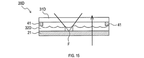
- the head-up display 4 of the fourth embodiment is different from the above-described embodiment in that an image generation unit 20D having a plurality of lenticular lenses that are concave lenses is provided.
- the stereoscopic display device 10 includes an image generation unit 20D.
- the image generation unit 20D includes, in addition to the liquid crystal panel 21 described above, a pixel lenticular 31D and a subpixel lenticular 32D.
- the pixel lenticular 31D and the sub-pixel lenticular 32D are concave lenses, respectively, and are configured as lenticular lenses.
- the focal position F of the pixel lenticular 31D and the sub-pixel lenticular 32D held in this manner is set to be on the surface of the liquid crystal panel 21, that is, on the surface of the liquid crystal panel 21 on the stereoscopic viewing lenticular 16 side.
- the focal position F of the pixel lenticular 31D and the sub-pixel lenticular 32D is on the surface of the liquid crystal panel 21.
- the image generation units 20B, 20C, and 20D are configured to laminate a plurality of lenticular lenses on one side of the liquid crystal panel 21.
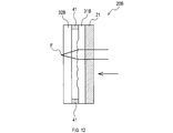
- the head-up display 5 of the fifth embodiment is different from the above-described embodiment in that it includes an image generation unit 20E in which a plurality of lenticular lenses are disposed to sandwich the liquid crystal panel 21.
- the stereoscopic display 10 includes an image generation unit 20E.
- the image generation unit 20E includes a pixel lenticular 31E and a sub-pixel lenticular 32E in addition to the liquid crystal panel 21 described above.
- the pixel lenticular 31 E is disposed in contact with the liquid crystal panel 21 on the light source 11 side of the liquid crystal panel 21, and the horizontal diffusion plate 26 and the sub-pixel lenticular 32 E are disposed on the side of the stereoscopic viewing lenticular 16 and the projection lens 17 of the liquid crystal panel 21.
- the liquid crystal panel 21 is disposed in contact with the liquid crystal panel 21. That is, since each of the lenticular lenses 31E and 32E is directly bonded to the liquid crystal panel 21, the spacer 41 is unnecessary.
- the pixel lenticular 31E and the sub-pixel lenticular 32E are respectively convex lenses and configured as lenticular lenses.
- the focal position F by the pixel lenticular 31D and the subpixel lenticular 32D held in this manner is set to be closer to the stereoscopic lenticular 16 than the subpixel lenticular 32D.
- the liquid crystal panel 21 is configured to transmit the light from the light source, and the pixel lenticular 31 E is disposed on the light source 11 side of the liquid crystal panel 21.
- the subpixel lenticular 32E is disposed on the side of the stereoscopic lenticular 16 and the projection lens 17 of the liquid crystal panel 21.
- the configuration in which the plurality of lenticular lenses are disposed to sandwich the liquid crystal panel 21 includes the image generation unit 20E having the plurality of lenticular lenses made of convex lenses.
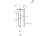
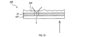
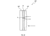
- the sixth embodiment is different from the fifth embodiment in that an image generation unit 20F having a plurality of lenticular lenses consisting of a concave lens and a convex lens is provided.
- the stereoscopic display device 10 includes an image generation unit 20F.
- the image generation unit 20F includes a pixel lenticular 31F and a sub-pixel lenticular 32F in addition to the liquid crystal panel 21 described above.
- the pixel lenticule 31F is disposed in contact with the liquid crystal panel 21 on the light source 11 side of the liquid crystal panel 21 and is configured as a convex lens.
- the sub-pixel lenticular 32E is disposed to be in contact with the liquid crystal panel 21 on the stereoscopic viewing lenticular 16 side of the liquid crystal panel 21, and is configured as a concave lens.
- the focal position F of the pixel lenticular 31 F and the sub-pixel lenticular 32 F is configured to be on the surface of the liquid crystal panel 21. 6-3. effect] According to the sixth embodiment described above, the effect (1a) of the first embodiment described above is exhibited, and further, the following effect is exhibited.
- the focal position F of the pixel lenticular 31F and the sub-pixel lenticular 32F is on the surface of the liquid crystal panel 21.
- liquid crystal panel 21 in which the coloring portions 21R, 21G, and 21B are disposed as shown in FIG. 3 is used, but the present invention is not limited to this.
- a liquid crystal panel 21A as shown in FIG. 21 may be used.
- the color developing portions 21R, 21G, and 21B is configured to be arranged in the order of G, B, R, G, B, and R. Further, in the lower stage, the coloring portions 21R, 21G, and 21B are arranged in the order of B, R, G, B, R, and G.
- pixel elements for one pixel can be configured by using the colored portions 21R, 21G, and 21B aligned in the vertical direction, and therefore, the liquid crystal panel 21A and the lenses 23 and 32 do not have to be arranged obliquely.
- the longitudinal direction can be aligned with the vertical direction, and the lateral direction can be aligned with the horizontal direction. In this configuration, it is possible to improve the utilization efficiency of the pixels constituting the liquid crystal panel 21A.
- the liquid crystal panel 21A and the lens 23 are used in a normal liquid crystal panel in which pixel elements for one pixel are formed using the color forming portions 21R, 21G, and 21B aligned in the horizontal direction. , 32 may be adopted without being inclined.
- the liquid crystal panel 21 is adopted, and the color forming portions 21R, 21G, and 21B are configured to emit light by transmitting the backlight, but the invention is not limited to this.
- a configuration may be adopted in which an organic EL display or the like emits light by emitting light from the color forming portions 21R, 21G, 21B. This configuration can be applied to the configurations of the first to fourth embodiments.
- the microlenses constituting the sub-pixel MLA 23 are configured to have the same curvature in the vertical direction and the horizontal direction, but the present invention is not limited to this.
- the microlens may be configured as an MLA having different curvatures in the vertical direction and the horizontal direction.
- the plurality of functions of one component in the above embodiment may be realized by a plurality of components, or one function of one component may be realized by a plurality of components . Also, a plurality of functions possessed by a plurality of components may be realized by one component, or one function realized by a plurality of components may be realized by one component.
- part of the configuration of the above embodiment may be omitted. Further, at least a part of the configuration of the above-described embodiment may be added to or replaced with the configuration of the other above-described embodiment.
- all the aspects contained in the technical thought specified from the wording described in the claim are an embodiment of this indication.
- the light source 11 and the illumination lens 12 correspond to the light providing unit in the present disclosure
- the liquid crystal panel 21 corresponds to the image display unit in the present disclosure
- the sub pixel MLA 23, the horizontal diffusion plate 26 and the sub pixel lenticular 32B, 32C, 32D, 32E, and 32F, and pixel centiculums 31B, 31C, 31D, 31E, and 31F correspond to the color forming / refraction portions in the present disclosure.
- the horizontal diffuser plate 26 corresponds to the second refracting portion in the sub-pixel lenticulars 32B, 32C, 32D, 32E, and 32F in this disclosure, and is a vertical lenticular lens in the pixel centicurities 31B, 31C, 31D, 31E, and 31F in this disclosure. It corresponds to In addition, the sub-pixel lenticulars 32B, 32C, 32D, 32E, and 32F correspond to the horizontal lenticular lenses described in the present disclosure, and correspond to the microlens array described in the sub-pixel MLA disclosed the present invention.
Landscapes
- Physics & Mathematics (AREA)
- Engineering & Computer Science (AREA)
- General Physics & Mathematics (AREA)
- Optics & Photonics (AREA)
- Multimedia (AREA)
- Signal Processing (AREA)
- Chemical & Material Sciences (AREA)
- Combustion & Propulsion (AREA)
- Transportation (AREA)
- Mechanical Engineering (AREA)
- Geometry (AREA)
- Testing, Inspecting, Measuring Of Stereoscopic Televisions And Televisions (AREA)
- Stereoscopic And Panoramic Photography (AREA)
- Instrument Panels (AREA)
Priority Applications (3)
| Application Number | Priority Date | Filing Date | Title |
|---|---|---|---|
| CN201880049908.8A CN110998416A (zh) | 2017-08-09 | 2018-08-06 | 立体显示装置 |
| DE112018004062.3T DE112018004062B4 (de) | 2017-08-09 | 2018-08-06 | Dreidimensionale anzeigevorrichtung |
| US16/780,263 US20200174279A1 (en) | 2017-08-09 | 2020-02-03 | Three-dimensional display device |
Applications Claiming Priority (2)
| Application Number | Priority Date | Filing Date | Title |
|---|---|---|---|
| JP2017-154153 | 2017-08-09 | ||
| JP2017154153A JP6791058B2 (ja) | 2017-08-09 | 2017-08-09 | 立体表示装置 |
Related Child Applications (1)
| Application Number | Title | Priority Date | Filing Date |
|---|---|---|---|
| US16/780,263 Continuation US20200174279A1 (en) | 2017-08-09 | 2020-02-03 | Three-dimensional display device |
Publications (1)
| Publication Number | Publication Date |
|---|---|
| WO2019031443A1 true WO2019031443A1 (ja) | 2019-02-14 |
Family
ID=65271655
Family Applications (1)
| Application Number | Title | Priority Date | Filing Date |
|---|---|---|---|
| PCT/JP2018/029388 Ceased WO2019031443A1 (ja) | 2017-08-09 | 2018-08-06 | 立体表示装置 |
Country Status (5)
| Country | Link |
|---|---|
| US (1) | US20200174279A1 (https=) |
| JP (1) | JP6791058B2 (https=) |
| CN (1) | CN110998416A (https=) |
| DE (1) | DE112018004062B4 (https=) |
| WO (1) | WO2019031443A1 (https=) |
Cited By (4)
| Publication number | Priority date | Publication date | Assignee | Title |
|---|---|---|---|---|
| CN111948813A (zh) * | 2019-05-17 | 2020-11-17 | 未来(北京)黑科技有限公司 | 一种抬头显示系统 |
| CN112034619A (zh) * | 2019-05-17 | 2020-12-04 | 未来(北京)黑科技有限公司 | 一种光线控制装置和被动发光像源 |
| WO2023008576A1 (ja) * | 2021-07-30 | 2023-02-02 | 大日本印刷株式会社 | コンバイナ、ヘッドアップディスプレイ、移動体、及び自動車 |
| WO2024106359A1 (ja) * | 2022-11-15 | 2024-05-23 | Scivax株式会社 | 光学系装置および光学素子 |
Families Citing this family (25)
| Publication number | Priority date | Publication date | Assignee | Title |
|---|---|---|---|---|
| CN114815287B (zh) | 2017-08-23 | 2024-08-13 | 交互数字麦迪逊专利控股公司 | 用于生成投影3d光场的光场图像引擎方法和装置 |
| KR102794040B1 (ko) * | 2018-08-29 | 2025-04-14 | 피씨엠에스 홀딩스, 인크. | 모자이크 주기적 층에 기반한 광 필드 디스플레이를 위한 광학 방법 및 시스템 |
| US11181742B2 (en) * | 2018-10-05 | 2021-11-23 | Samsung Electronics Co., Ltd. | Display panel, and 3D display device and 3D head up display (HUD) device using the display panel |
| CN109581729A (zh) * | 2019-01-03 | 2019-04-05 | 京东方科技集团股份有限公司 | 一种显示面板及显示装置 |
| JP6926136B2 (ja) * | 2019-03-22 | 2021-08-25 | 矢崎総業株式会社 | ヘッドアップディスプレイ装置 |
| JP7390558B2 (ja) * | 2019-03-27 | 2023-12-04 | パナソニックIpマネジメント株式会社 | 虚像表示システム、画像表示方法、ヘッドアップディスプレイ、及び移動体 |
| WO2020262438A1 (ja) * | 2019-06-25 | 2020-12-30 | 日本精機株式会社 | 車両用表示装置 |
| WO2020262441A1 (ja) * | 2019-06-25 | 2020-12-30 | 日本精機株式会社 | 車両用表示装置 |
| JP7188354B2 (ja) * | 2019-10-24 | 2022-12-13 | 株式会社デンソー | ウィンドシールド表示装置 |
| AU2020383516A1 (en) * | 2019-11-12 | 2022-05-26 | Light Field Lab, Inc. | Relay systems |
| JP7354846B2 (ja) * | 2020-01-15 | 2023-10-03 | 日本精機株式会社 | ヘッドアップディスプレイ装置 |
| CN111650754B (zh) * | 2020-07-17 | 2022-08-12 | 北京耐德佳显示技术有限公司 | 一种平视显示设备 |
| JP7519254B2 (ja) * | 2020-10-05 | 2024-07-19 | 株式会社小糸製作所 | 画像投影装置および車両用情報表示装置 |
| US12250360B2 (en) | 2021-01-25 | 2025-03-11 | Boe Technology Group Co., Ltd. | Display apparatus with light-splitting component and driving method thereof |
| US12051344B2 (en) * | 2021-01-25 | 2024-07-30 | Boe Technology Group Co., Ltd. | Display apparatus with light-splitting component and driving method thereof |
| US12294689B2 (en) | 2021-01-25 | 2025-05-06 | Boe Technology Group Co., Ltd. | Display apparatus of light-splitting structure and driving method thereof |
| CN115685580B (zh) * | 2021-07-23 | 2025-03-25 | 京东方科技集团股份有限公司 | 一种3d显示装置以及改善图像串扰分布的方法 |
| CN113687523B (zh) * | 2021-08-05 | 2022-05-17 | 中山大学 | 一种基于投射光非对称分布的裸眼光场显示方法 |
| JP2023158670A (ja) * | 2022-04-19 | 2023-10-31 | 日本放送協会 | 拡散スクリーン及び多視点映像表示装置 |
| EP4300168A1 (en) | 2022-06-28 | 2024-01-03 | N. S. International Ltd. | Local dimming system for head up display |
| WO2024071713A1 (ko) | 2022-09-26 | 2024-04-04 | 삼성전자주식회사 | 입체 표시 장치 및 입체 표시 방법 |
| CN119213758A (zh) | 2022-09-26 | 2024-12-27 | 三星电子株式会社 | 立体显示装置及立体显示方法 |
| CN117518569A (zh) * | 2023-03-30 | 2024-02-06 | 武汉华星光电技术有限公司 | 显示面板和电子终端 |
| CN119148377A (zh) * | 2023-06-09 | 2024-12-17 | 深圳引望智能技术有限公司 | 一种三维显示装置、三维投影光源以及交通工具 |
| US12549704B2 (en) * | 2024-06-03 | 2026-02-10 | Ford Global Technologies, Llc | Dual view display |
Citations (5)
| Publication number | Priority date | Publication date | Assignee | Title |
|---|---|---|---|---|
| JPH095672A (ja) * | 1995-06-23 | 1997-01-10 | Sharp Corp | 3次元情報再生装置 |
| WO2010084834A1 (ja) * | 2009-01-23 | 2010-07-29 | ソニー株式会社 | 空間像表示装置 |
| JP2011085790A (ja) * | 2009-10-16 | 2011-04-28 | Seiko Epson Corp | 電気光学装置及び電子機器 |
| JP2012093506A (ja) * | 2010-10-26 | 2012-05-17 | Denso Corp | ヘッドアップディスプレイ装置 |
| US20160357494A1 (en) * | 2015-06-05 | 2016-12-08 | Beijing Zhigu Rui Tuo Tech Co., Ltd | Display control methods and apparatuses |
Family Cites Families (15)
| Publication number | Priority date | Publication date | Assignee | Title |
|---|---|---|---|---|
| ES2013569A6 (es) * | 1989-06-21 | 1990-05-01 | Dominguez Montes Juan | Pantalla mejorada para reproduccion de imagenes tridimensionales e estaticas o en movimiento y procedimiento para fabricarla. |
| JPH08322067A (ja) * | 1995-05-24 | 1996-12-03 | Sharp Corp | 3次元情報再生装置 |
| JP3728013B2 (ja) * | 1996-05-20 | 2005-12-21 | キヤノン株式会社 | 立体画像表示装置 |
| JP3703225B2 (ja) * | 1996-09-02 | 2005-10-05 | キヤノン株式会社 | 立体画像表示方法及びそれを用いた立体画像表示装置 |
| EP1045596A2 (en) * | 1999-04-12 | 2000-10-18 | Mixed Reality Systems Laboratory Inc. | Stereoscopic image display apparatus |
| JP2001211465A (ja) * | 1999-11-15 | 2001-08-03 | Hit Design:Kk | 3次元画像表示方法およびそれを用いた3次元画像表示装置 |
| JP2005284044A (ja) * | 2004-03-30 | 2005-10-13 | Canon Inc | 立体画像表示装置 |
| CN1322353C (zh) * | 2005-09-02 | 2007-06-20 | 上海大数智能系统有限公司 | 渐变斜度微透镜阵列视差宽屏自动立体显示器 |
| JP2008015395A (ja) * | 2006-07-10 | 2008-01-24 | Matsushita Electric Ind Co Ltd | 立体画像表示装置 |
| JP2009063892A (ja) * | 2007-09-07 | 2009-03-26 | Seiko Epson Corp | プロジェクタ、光学素子及び光変調装置 |
| JP5439686B2 (ja) | 2010-07-07 | 2014-03-12 | 国立大学法人東京農工大学 | 立体画像表示装置及び立体画像表示方法 |
| JP2014045466A (ja) * | 2012-08-29 | 2014-03-13 | Lenovo Singapore Pte Ltd | 立体映像表示システム、立体映像データの設定方法および観察位置の変更方法 |
| JP6277544B2 (ja) * | 2013-02-27 | 2018-02-14 | Tianma Japan株式会社 | 立体画像表示装置、端末装置 |
| CN104423051A (zh) * | 2013-09-10 | 2015-03-18 | 大昱光电股份有限公司 | 立体显示装置 |
| CN205384410U (zh) * | 2015-12-17 | 2016-07-13 | 张家港康得新光电材料有限公司 | 3d显示膜及立体显示装置 |
-
2017
- 2017-08-09 JP JP2017154153A patent/JP6791058B2/ja active Active
-
2018
- 2018-08-06 WO PCT/JP2018/029388 patent/WO2019031443A1/ja not_active Ceased
- 2018-08-06 DE DE112018004062.3T patent/DE112018004062B4/de not_active Expired - Fee Related
- 2018-08-06 CN CN201880049908.8A patent/CN110998416A/zh active Pending
-
2020
- 2020-02-03 US US16/780,263 patent/US20200174279A1/en not_active Abandoned
Patent Citations (5)
| Publication number | Priority date | Publication date | Assignee | Title |
|---|---|---|---|---|
| JPH095672A (ja) * | 1995-06-23 | 1997-01-10 | Sharp Corp | 3次元情報再生装置 |
| WO2010084834A1 (ja) * | 2009-01-23 | 2010-07-29 | ソニー株式会社 | 空間像表示装置 |
| JP2011085790A (ja) * | 2009-10-16 | 2011-04-28 | Seiko Epson Corp | 電気光学装置及び電子機器 |
| JP2012093506A (ja) * | 2010-10-26 | 2012-05-17 | Denso Corp | ヘッドアップディスプレイ装置 |
| US20160357494A1 (en) * | 2015-06-05 | 2016-12-08 | Beijing Zhigu Rui Tuo Tech Co., Ltd | Display control methods and apparatuses |
Cited By (4)
| Publication number | Priority date | Publication date | Assignee | Title |
|---|---|---|---|---|
| CN111948813A (zh) * | 2019-05-17 | 2020-11-17 | 未来(北京)黑科技有限公司 | 一种抬头显示系统 |
| CN112034619A (zh) * | 2019-05-17 | 2020-12-04 | 未来(北京)黑科技有限公司 | 一种光线控制装置和被动发光像源 |
| WO2023008576A1 (ja) * | 2021-07-30 | 2023-02-02 | 大日本印刷株式会社 | コンバイナ、ヘッドアップディスプレイ、移動体、及び自動車 |
| WO2024106359A1 (ja) * | 2022-11-15 | 2024-05-23 | Scivax株式会社 | 光学系装置および光学素子 |
Also Published As
| Publication number | Publication date |
|---|---|
| DE112018004062T5 (de) | 2020-04-16 |
| DE112018004062B4 (de) | 2023-05-25 |
| JP6791058B2 (ja) | 2020-11-25 |
| JP2019032467A (ja) | 2019-02-28 |
| US20200174279A1 (en) | 2020-06-04 |
| CN110998416A (zh) | 2020-04-10 |
Similar Documents
| Publication | Publication Date | Title |
|---|---|---|
| JP6791058B2 (ja) | 立体表示装置 | |
| KR101195653B1 (ko) | 표시 장치, 표시 방법 및 헤드-업 디스플레이 | |
| US10684408B2 (en) | Display device and image display method | |
| US9274345B2 (en) | Multiple view display | |
| US20130257689A1 (en) | Display device | |
| US20100027113A1 (en) | Display device | |
| US20080186575A1 (en) | 2d-3d image switching display system | |
| EP1418458A1 (en) | Direct retinal projection head mounted display | |
| JP6913441B2 (ja) | 画像表示装置 | |
| JP2011085790A (ja) | 電気光学装置及び電子機器 | |
| JP5943747B2 (ja) | 立体映像表示装置 | |
| CN110088666B (zh) | 头戴式显示器及其光学系统 | |
| KR20140040650A (ko) | 유기발광 표시장치 | |
| KR20160085887A (ko) | 듀얼 뷰잉 필름 및 이를 사용한 듀얼 뷰 디스플레이 장치 | |
| JP7456050B2 (ja) | 表示装置 | |
| JPH10170860A (ja) | 眼球投影型映像表示装置 | |
| CN106444058A (zh) | 虚拟现实显示头戴设备及光学组件 | |
| JP4945691B2 (ja) | 表示装置、表示方法及びヘッドアップディスプレイ | |
| JP2021097035A (ja) | バックライトモジュール | |
| JP2005316270A (ja) | 表示装置 | |
| CN116794841A (zh) | 抬头显示系统和车辆 | |
| WO2020031549A1 (ja) | 虚像表示装置 | |
| CN119866466A (zh) | 一种图像生成装置、显示设备、交通工具和图像生成方法 | |
| US20230359063A1 (en) | Integrated stereoscopic image display device | |
| JP2016184006A (ja) | 画像表示装置 |
Legal Events
| Date | Code | Title | Description |
|---|---|---|---|
| 121 | Ep: the epo has been informed by wipo that ep was designated in this application |
Ref document number: 18843535 Country of ref document: EP Kind code of ref document: A1 |
|
| 122 | Ep: pct application non-entry in european phase |
Ref document number: 18843535 Country of ref document: EP Kind code of ref document: A1 |